Embed Size (px)
Citation preview

Journal of Engineering Science and Technology Vol. 6, No. 3 (2011) 300 - 310 © School of Engineering, Taylor’s University
300
HARMONIC LOAD FLOW FOR RADIAL DISTRIBUTION SYSTEMS
A. ARUNAGIRI1,*, B. VENKATESH
2
1EEET Department, Yanbu Industrial College, Kingdom of Saudi Arabia 2Faculty of Engineering Architecture and Science, Ryerson University,
Toronto, Canada
*Corresponding Author: [email protected]
Abstract
Radial distribution systems (RDS) require special load flow methods to solve
power flow equations owing to their high R/X ratio. Increasing use of power
electronic devices and effect of magnetic saturation cause harmonics in RDS.
This paper proposes a novel algorithm to compute the power flow solution of a
RDS accounting for all the harmonic components. It uses a recursive solution
technique. The proposed method uses a novel dynamic data structure reported
in the paper. The proposed method is tested upon a 33-bus RDS and the results
are reported.
Keywords: Radial distribution systems, Magnetic saturation, Harmonics,
Dynamic data structure.
1. Introduction
Analysis of distribution systems using power flow is important in the field of
power systems. Distribution systems are predominantly characterized by their
high R/X ratio and radial topology. Matrix based iterative methods do not lend
themselves for radial distribution systems owing to these characteristics.
Numerous algorithms have been developed using simple recursive equations [1-
3]. Rapid industrialization has led to increasing use of power electronic devices in
transmission and distribution systems. Modern industrial and domestic consumers
use an ever-increasing number of devices that primarily employ power electronics
based power-conditioners. Use of AC machines employing magnetic circuits in
the saturated region also introduces harmonics in electric power systems.
Numerous power flow methods have been reported in literature that is meant to
handle harmonics [4]. These methods seldom address radial distribution systems.
Harmonic Load Flow for Radial Distribution Systems 301
Journal of Engineering Science and Technology June 2011, Vol. 6(3)
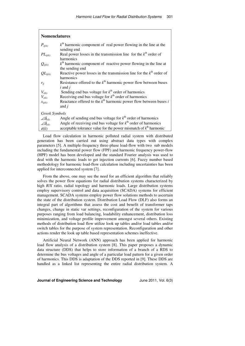
Nomenclatures
Pij(k) kth
harmonic component of real power flowing in the line at the
sending end
PLij(k) Real power losses in the transmission line for the kth
order of
harmonics
Qij(k) kth
harmonic component of reactive power flowing in the line at
the sending end
QLij(k) Reactive power losses in the transmission line for the kth
order of
harmonics
rij
Resistance offered to the kth
harmonic power flow between buses
i and j
Vi(k) Sending end bus voltage for kth
order of harmonics
Vj(k) Receiving end bus voltage for kth
order of harmonics
xij(k) Reactance offered to the kth
harmonic power flow between buses i
and j
Greek Symbols
∠δi(k) Angle of sending end bus voltage for kth
order of harmonics
∠δj(k) Angle of receiving end bus voltage for kth
order of harmonics
ε(k) acceptable tolerance value for the power mismatch of kth harmonic
Load flow calculation in harmonic polluted radial system with distributed
generation has been carried out using abstract data types with complex
parameters [5]. A multiple-frequency three-phase load-flow with two sub models
including the fundamental power flow (FPF) and harmonic frequency power-flow
(HPF) model has been developed and the standard Fourier analysis was used to
deal with the harmonic loads to get injection currents [6]. Fuzzy number based
methodology for harmonic load-flow calculation including uncertainties has been
applied for interconnected system [7].
From the above, one may see the need for an efficient algorithm that reliably
solves the power flow equations for radial distribution systems characterized by
high R/X ratio, radial topology and harmonic loads. Large distribution systems
employ supervisory control and data acquisition (SCADA) systems for efficient
management. SCADA systems employ power flow solutions methods to ascertain
the state of the distribution system. Distribution Load Flow (DLF) also forms an
integral part of algorithms that assess the cost and benefit of transformer taps
changes, change in static var settings, reconfiguration of the system for various
purposes ranging from load balancing, loadability enhancement, distribution loss
minimization, and voltage profile improvement amongst several others. Existing
methods of distribution load flow utilize look up tables and/or load tables and/or
switch tables for the purpose of system representation. Reconfiguration and other
actions render the look up table based representation schemes ineffective.
Artificial Neural Network (ANN) approach has been applied for harmonic
load flow analysis of a distribution system [8]. This paper proposes a dynamic
data structure (DDS) that helps to store information of a branch of a RDS to
determine the bus voltages and angle of a particular load pattern for a given order
of harmonics. This DDS is adaptation of the DDS reported in [9]. These DDS are
handled as a linked list representing the entire radial distribution system. A

302 A. Arunagiri and B.Venkatesh
Journal of Engineering Science and Technology June 2011, Vol. 6(3)
pseudo code that generates the DDS for a RDS is presented. A function is then
developed that computes the voltages from the farthermost end up to the head of
the branch. This function is called recursively to find out voltages at all branches
of the RDS from the farthermost branch up to the branches emanating from the
main substation of the RDS. A pseudo code for this recursive function is also
presented. The resulting DLF algorithm is computationally efficient and can deal
with the topology changes quickly. The proposed method allows modeling of
loads of any type, any number of harmonic components and radial system of any
configuration with respect to buses and branches.
2. RDS Representation Using Dynamic Data Structure
Consider a radial distribution system shown in Fig. 1. This system represents
typical RDS. It has several branches and buses. The dynamic data structure must
represent the RDS or an integral part of the RDS. The proposed DDS represents
an integral part of the RDS, namely a generic branch. This section presents the
details of the proposed novel DDS that is used to store details of a branch.
The following attributes were envisioned while developing the proposed DDS.
(a) The data structure must be dynamic in nature so that it may be created and
altered in the execution stage.
(b) DDS required for holding the information of a branch must be compact and
addressable from any function.
(c) It must be flexible to accommodate any number of buses and harmonic loads
within a branch.
(d) It must be flexible to address as many data structures of branches that emanate
from the end of a branch.
The proposed data structure of a branch needs to hold the details of:
(a) Parent bus to which the branch is connected,
(b) Number of buses in the branch.
(c) An array to store IDs of all the buses in the order of their location from the
head of the branch,
(d) Details of line resistance and reactance for various harmonic components with
in a branch,
(e) Number of branches emanating from the last bus of this branch,
01 03 0402 05 06 07 08 09 10 11
12 13 14 15 16
17 18 19 20 21
I II
IV
V
III
Fig. 1. A Simple Radial Network with Several Branches.
Harmonic Load Flow for Radial Distribution Systems 303
Journal of Engineering Science and Technology June 2011, Vol. 6(3)
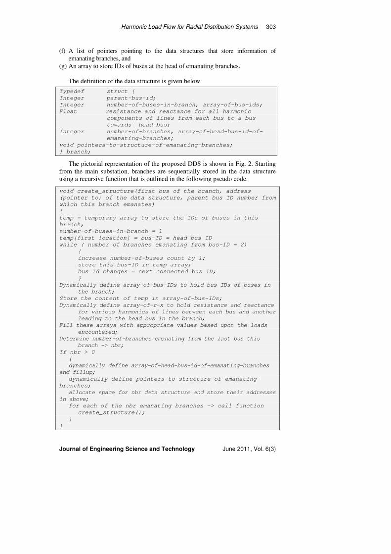
(f) A list of pointers pointing to the data structures that store information of
emanating branches, and
(g) An array to store IDs of buses at the head of emanating branches.
The definition of the data structure is given below.
Typedef struct {
Integer parent-bus-id;
Integer number-of-buses-in-branch, array-of-bus-ids;
Float resistance and reactance for all harmonic
components of lines from each bus to a bus
towards head bus;
Integer number-of-branches, array-of-head-bus-id-of-
emanating-branches;
void pointers-to-structure-of-emanating-branches;
} branch;
The pictorial representation of the proposed DDS is shown in Fig. 2. Starting
from the main substation, branches are sequentially stored in the data structure
using a recursive function that is outlined in the following pseudo code.
void create_structure(first bus of the branch, address
(pointer to) of the data structure, parent bus ID number from
which this branch emanates)
{
temp = temporary array to store the IDs of buses in this
branch;
number-of-buses-in-branch = 1
temp[first location] = bus-ID = head bus ID
while ( number of branches emanating from bus-ID = 2)
{
increase number-of-buses count by 1;
store this bus-ID in temp array;
bus Id changes = next connected bus ID;
}
Dynamically define array-of-bus-IDs to hold bus IDs of buses in
the branch;
Store the content of temp in array-of-bus-IDs;
Dynamically define array-of-r-x to hold resistance and reactance
for various harmonics of lines between each bus and another
leading to the head bus in the branch;
Fill these arrays with appropriate values based upon the loads
encountered;
Determine number-of-branches emanating from the last bus this
branch -> nbr;
If nbr > 0
{
dynamically define array-of-head-bus-id-of-emanating-branches
and fillup;
dynamically define pointers-to-structure-of-emanating-
branches;
allocate space for nbr data structure and store their addresses
in above;
for each of the nbr emanating branches -> call function
create_structure();
}
}

304 A. Arunagiri and B.Venkatesh
Journal of Engineering Science and Technology June 2011, Vol. 6(3)
The pseudo code presented above creates a structure for a branch. Starting at the
main substation bus, the pseudo code forms the first branch by sequentially
considering buses until it finds one that has several branches emanating from it.
Referring to Fig. 1 that presents a sample radial system, it builds the first branch
from bus 1 up to bus 3 where two branches emanate. The data structure created for
branch labeled I, starts with bus 01 and ends with bus 03 comprising three buses. It
has two branches emanating from it namely II and III. This structure stores pointers
that point towards the structures storing details of branches II and III. The pseudo
code calls itself twice, once each for branches II and III. This process proceeds until
data structure for all the branches are built. A pictorial representation of the data
structure storing details of branch II is shown in Fig. 3. The DDS proposed in this
paper is highly flexible and is convenient to use when the RDS is reconfigured
under the umbrella of SCADA. This build up of DDS to represent the entire RDS is
convenient for the solving the power flow equations for the entire radial network
using a recursive function outlined in the next section.
3. Proposed Harmonic Distribution Load Flow
Distribution power flow is presented in this section. It uses the dynamic data
structure proposed in Section 2. First the line model of a generic line is presented
parent-bus-id
number-of-buses-
in-branch number-of-branches
emanating
.
.
.
.
.
.
.
.
Arr
ay o
f b
use
s
Arr
ay o
f li
ne
resi
stan
ce
Arr
ay o
f li
ne
reac
tan
ce[1
]
Arr
ay o
f li
ne
reac
tan
ce[n
h]
po
inte
rs-t
o-s
tru
ctu
re-o
f-
ema
na
tin
g-b
ran
ches
arra
y-o
f-h
ead
-bu
s-id
-of-
eman
atin
g-b
ran
ches
Fig. 2. Proposed DDS with nh Harmonics. Components.
03
03 02
Fig. 3. Example of Dynamic Data Structure-Branch II.
04 r03-04 x03-04(1) . x03-04(nh)
05 r04-05 x04-05(1) . x04-05(nh)
06 r05-06 x05-06(1) . x05-06(nh)
07
17
V
IV

Harmonic Load Flow for Radial Distribution Systems 305
Journal of Engineering Science and Technology June 2011, Vol. 6(3)
with modelling for harmonics. Then a recursive algorithm is presented. This is
followed by the flowchart of the proposed harmonic distribution load flow.
3.1. Line model and voltage equation considering harmonics
In this section, a simple circuit model of a transmission line considering kth
order
harmonic component and associated recursive voltage equations is presented. It is
assumed that the three-phase RDS is balanced and can be represented by an
equivalent single-phase system. The transmission line to ground capacitance
elements at the distribution voltage level are small and thus neglected. A simple
circuit model of a transmission line is shown in Fig. 4.
The values of Vi(k)∠δi(k) and Vj(k)∠δj(k) represent the sending and receiving end
voltages. The values rij + j xij(k) represent resistance and reactance offered to the
kth
harmonic power flow between buses i and j. Several methods of solving the
power flow equations of distribution systems have been proposed [1-3]. It may be
observed that these methods use recursive equations as below in several forms
considering either sending or receiving end power (Fig. 4 for the variables used):
(a) Equation derived considering sending end powers of kth
harmonic:
( )( )( )
2
)(
2
)(
2
)(
2
)(
2
)()()(
2
)(
2
)( 2ki
kijkijkijij
kijkijkijijkikjV
QPxrQxPrVV
++++−= (1)
where Pij(k) and Qij(k) refer to the kth
harmonic component power flowing in the
line at the sending end.
(b) Equation derived considering receiving end powers of kth
harmonic:
( )( )2
)(
2
)(
2
)(
2
22
)(
)()()(
2
)(
)()()(
2
)(22
kijkijkijij
ki
kijkijkijij
ki
kijkijkijijkj QPxrV
QxPrV
QxPrV ++−
−+−
−+−=
(2)
where Pij(k) and Qij(k) refer to the kth
harmonic component of power flowing in the
line at the receiving end. These equations are not amenable for matrix computation as
in the case of conventional methods of solving power flow equations for transmission
grids like NR method or Fast De-coupled Load Flow method.
3.2. Line model and voltage equation considering harmonics
The proposed recursive algorithm to compute the voltage solution of the RDS is
presented in this section. The routine starts by computing voltage from the
farthermost bus of the first branch. If the branch has other branches emanating,
Sending end:
Vi(k)∠δi(k)
Iij(k)∠αij(k)
Receiving end:
Vj(k)∠δj(k)
rij + j xij(k)
Fig. 4. Simple Equivalent Circuit of
Transmission Line Considering Harmonics.

306 A. Arunagiri and B.Venkatesh
Journal of Engineering Science and Technology June 2011, Vol. 6(3)
the pseudo code recursively calls itself to compute the state of buses in these
branches and the power they draw from the farthermost bus. This recursive call is
continued until the branches from where other branches do not emanate. Then, the
pseudo code computes the voltage at farthermost bus using (2) with the
knowledge of its load. Then using the expressions below, it computes the power
loss in the transmission line connecting this bus and next bus in the direction
leading to the first bus of the branch.
( )
+=
+=
2
)(
2
)(
2
)(
)(
2
)(
2
)(
2
)(
)(
kj
kijkij
kijkij
kj
kijkij
ijkij
V
QPxQL
V
QPrPL
(3)
where PLij(k) and QLij(k) are the real and reactive power losses in the
transmission line model shown in Fig. 4 and Pij(k) and Qij(k) refer to the power
flowing in the line at the receiving end corresponding to the kth
harmonic
component. With load at bus j and transmission power loss in the line between
buses i and j known, the pseudo code computes the load at bus i. This process
continues until the voltage is computed until the first bus. The phase angle of the
voltage phasor at the jth
bus is computed by the following expression:
−−−= −
2
)()(
)()()(1
)()( 1coskjki
ijkijkijkij
kikjVV
rQxPδδ (4)
where Pij(k) and Qij(k) refer to the power flowing in the line at the receiving end
corresponding to the kth
component. During each computation, it repeats the
solution for each harmonic component.
In this work convergence is checked by ascertaining whether the sum of
powers flowing out in the lines connected to each bus equals, or nearly equals
within a tolerable limit, the net power injected in to that bus by the connected
generations and loads. Mathematically, convergence criterion is represented as
( ){ } ( )kYVVPDPGj
kijkjkikijkjkikiki εθδδ ≤
−−−− ∑ )()()()()()()()( cos (5)
( ){ } ( )kYVVQDQGj
kijkjkikijkjkikiki εθδδ ≤
−−−− ∑ )()()()()()()()( sin (6)
where ε(k) is an acceptable tolerance value kth
harmonic.
3.3. Overall algorithm
This section presents the details of the proposed method that uses the novel data
structure and the proposed recursive algorithm. The overall algorithm is presented
in Fig. 5. The algorithm reads in the data at first. It then creates one DDS each to
represent all the branches of the RDS. The down stream harmonics are considered

Harmonic Load Flow for Radial Distribution Systems 307
Journal of Engineering Science and Technology June 2011, Vol. 6(3)
to generate appropriate reactance values of all the lines. The DDS and pseudo
code required are presented in Section 2. Subsequently, the algorithm calls the
function calculate load / generation () recursively to compute the voltage solution
at all the buses in the system. The algorithm checks for convergence by checking
whether the inequalities (5) and (6) are satisfied. The function calculate load /
generation () is repeatedly called until the inequalities (5) and (6) are satisfied. In
the implementation of the overall algorithm, transformers are modelled using
conventional π-model. The effect of shunt compensating element at any bus is
considered. π-model of a transformer is used for all computations.
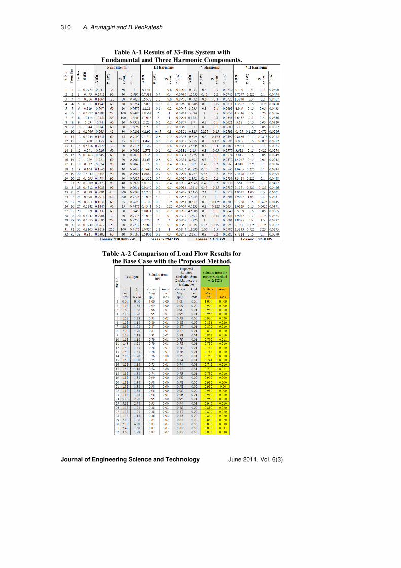
4. Results
To test the effectiveness of the proposed algorithm 33-bus is considered. The
single line diagram of the 33-bus RDS is presented in Fig. A-1 (Appendix A)
Three harmonic components namely 3, 5 and 7 are considered for the purpose of
simulation. The tolerance was chosen to be 0.001 p.u. It took seven iterations for
the proposed algorithm to converge in for the 33-bus RDS. The convergence
depends upon the base load condition and the chosen tolerance. The proposed
method is expected to give the power flow solution even for large systems with
minimum number of iterations. Table A-1 (Appendix A) presents the results of the
proposed method with voltage solution for various harmonics. Table A.2 presents
comparison of base case solution with solution from ladder iterative technique
and from BPN [8]. Figure A-2 (Appendix A) presents a graph that shows total
system loss variation with respect to harmonic components.
Fig. 5. Flowchart for the Overall Algorithm.
Start
Read in distribution
system details.
Create data structure for all
the branches
Compute the voltage solution using the
function:
calculate load / generation()
End
Compute the all buses if
inequalities (5-6) are
satisfied

308 A. Arunagiri and B.Venkatesh
Journal of Engineering Science and Technology June 2011, Vol. 6(3)
5. Conclusions
Inclusion of power electronic devices and saturation of magnetic circuits introduce
several load side harmonics. This paper reports a new distribution system load flow
algorithm that uses recursive voltage equations considering harmonic load
components. This paper proposes a new dynamic data structure for modular
representation of a radial distribution system with loads having harmonic
component. The DDS are stored and retrieved using a linked list. A recursive load
flow algorithm is then proposed that uses the dynamic data structure to solve the
power flow equations efficiently considering harmonic components. Pseudo codes
for generation of dynamic data structure are included. Results of the tests on a 33-
bus RDS with harmonic components are presented that demonstrates the
applicability of the method.
References
1. Kersting, W.H.; and Mendive, D.L. (1976). An application of ladder network
theory to the solution of three phase radial load flow problems. Proceeding of
IEEE PES, Winter Power Meeting Conference, New York, USA.
2. Kersting, W.H. (1984). A method to design and operation of distribution
system. IEEE Transactions on Power Apparatus and systems, PAS-103(7),
1945-1952.
3. Baran, M.E.; and Wu, F.F. (1989). Optimal sizing of capacitors placed on a radial
distribution system. IEEE Transactions on Power Delivery, 4(1), 735-743.
4. Herraiz, S.; Sainz, L.; and Clua, J. (2003). Review of harmonic load flow
formulations. IEEE Transactions on Power Delivery, 18(3), 1079–1087.
5. Bud, C.; Tomoiaga, B.; Chindris, M.; and Anderu A.S. (2007). The load
flow calculation in harmonic polluted radial electric networks with
distributed generation. Proceedings of the 9th
International conference on
Electrical power quality and Utilisation, Barcelona.
6. Lin, W.M.; Zhan, T.S.; and Tsay, M.T. (2004). Multiple-frequency three-
phase load flow for harmonic analysis. IEEE transactions on Power
Systems, 19(2), 897-904.
7. Romero, A.A.; Zini, H.C.; Ratta, G.; and Dib, R. (2008). A fuzzy number
based methodology for harmonic load-flow calculation, considering
uncertainties. Latin American Research, 38(3), 205-212.
8. Arunagiri, A.; Venkatesh, B.; and Ramasamy, K. (2006). Artificial neural
network approach-an application to radial load flow algorithm. IEICE
Electronics Express, 3(14), 353-360.
9. Venkatesh, B.; and Ranjan, R. (2003). Data structure for radial distribution
system load flow analysis. IEE Proceedings on Generation, Transmission
and Distribution, 150(1), 101-106.

Harmonic Load Flow for Radial Distribution Systems 309
Journal of Engineering Science and Technology June 2011, Vol. 6(3)
Appendix A
Fig. A-2 Graph of Variation in Losses with Harmonics.
Lo
sses
in
kW
III V VII
Order of Harmonic
Fig. A-1 33-Bus Radial Distribution System.
01
07
08
09
10
11
12
13
14
15
16
17
18
02
03
04
05
06
19
20
21
22
23
24
25
26
27
28
29
30
31
32
33
Legend
Substation
Bus
Line
Tie line
310 A. Arunagiri and B.Venkatesh
Journal of Engineering Science and Technology June 2011, Vol. 6(3)
Table A-1 Results of 33-Bus System with
Fundamental and Three Harmonic Components.
Table A-2 Comparison of Load Flow Results for
the Base Case with the Proposed Method.
![i .] APPROXIMATING HARMONIC FUNCTIONS 499€¦ · APPROXIMATING HARMONIC FUNCTIONS 499 THE APPROXIMATION OF HARMONIC FUNCTIONS BY HARMONIC POLYNOMIALS AND BY HARMONIC RATIONAL FUNCTIONS*](https://img.pdfslide.us/doc/110x75/5f0873ba7e708231d42214c2/i-approximating-harmonic-functions-499-approximating-harmonic-functions-499-the.jpg)