Embed Size (px)
Citation preview

E2333 / Nov 2005
Notebook PCHardware User’s Manual

2
Contents
1. Introducing the Notebook PC ..................................................................5
About This User’s Manual .......................................................................................... 6Notes For This Manual .......................................................................................... 6
Preparing your Notebook PC ..................................................................................... 9
2. Knowing the Parts...................................................................................11
Top Side ...................................................................................................................12
Bottom Side .............................................................................................................14
Right Side ................................................................................................................16
Left Side ...................................................................................................................18
Front Side ................................................................................................................19
Rear Side .................................................................................................................20
3. Getting Started ....................................................................................... 23
Power System ..........................................................................................................24Using AC Power ..................................................................................................24Using Battery Power............................................................................................24Charging the Battery Pack ..................................................................................24Powering ON the Notebook PC .......................................................................... 26The Power-On Self Test (POST) ......................................................................... 26Checking Battery Power ......................................................................................27Battery Care ........................................................................................................27Restarting or Rebooting ......................................................................................28Powering OFF .....................................................................................................28
Special Keyboard Functions ....................................................................................29Colored Hot Keys ................................................................................................29Keyboard as Cursors...........................................................................................30Microsoft Windows™ Keys .................................................................................30Keyboard as a Numeric Keypad ......................................................................... 31
Switches and Status Indicators ................................................................................31Switches ..............................................................................................................31Status Indicators ..................................................................................................32CD Player Control Buttons and Indicator (on selected models) ......................... 32

3
Contents
4. Using the Notebook PC ......................................................................... 35Models with Sonoma chipset .............................................................................. 36
Operating System ....................................................................................................36Support Software.................................................................................................36
Pointing Device ........................................................................................................ 36Using the Touchpad.............................................................................................37Touchpad Usage Illustrations ..............................................................................38Caring for the Touchpad ......................................................................................39
Storage Devices ....................................................................................................... 41PC Card (PCMCIA) Socket .................................................................................41Inserting a PC Card (PCMCIA) ........................................................................... 41Removing a PC Card (PCMCIA) ......................................................................... 41Optical Drive ........................................................................................................ 42Hard Disk Drive ...................................................................................................44Flash Memory Card Reader ................................................................................44Modem Connection .............................................................................................44IR Wireless Communication (on selected models) ............................................. 46Guidelines for using IR communication............................................................... 46Enabling Infrared .................................................................................................46Network Connection ............................................................................................47Bluetooth Wireless Connection (on selected models) ........................................ 48Wireless LAN Connection (on selected models) ................................................. 48
Power Management Modes .....................................................................................50Full Power Mode & Maximum Performance........................................................ 50ACPI ....................................................................................................................50Suspend Mode ....................................................................................................50Power Savings ....................................................................................................50Stand by and Hibernate.......................................................................................52
Appendix ..................................................................................................... 53
Optional Accessories ............................................................................................... 54
Glossary ...................................................................................................................56
Glossary ...................................................................................................................56
Declarations and Safety Statements ....................................................................... 60
Notebook PC Information.........................................................................................72

4
Contents

5
1. Introducing the Notebook PC
About This User’s ManualNotes For This ManualSafety PrecautionsPreparing your Notebook PC

1 Introducing the Notebook PC
6
About This User’s ManualYou are reading the Notebook PC User’s Manual. This User’s Manual provides information on thevarious components in the Notebook PC and how to use them. The following are major sections of thisUser’s Manuals:
1. Introducing the Notebook PCIntroduces you to the Notebook PC and this User’s Manual.
2. Knowing the PartsGives you information on the Notebook PC’s components.
3. Getting StartedGives you information on getting started with the Notebook PC.
4. Using the Notebook PCGives you information on using the Notebook PC’s components.
5. AppendixIntroduces you to optional accessories and gives additional information.
Notes For This ManualA few notes and warnings in bold are used throughout this guide that you should be aware of in order tocomplete certain tasks safely and completely. These notes have different degrees of importance asdescribed below:
NOTE: Tips and information for spe-cial situations.
TIP: Tips and useful information forcompleting tasks.
Text enclosed in < > or [ ] represents a key on the keyboard; do not actually type the <> or [ ] and the enclosed letters.
< >[ ]
WARNING! Important information thatmust be followed for safe operation.
IMPORTANT! Vital information thatmust be followed to prevent damageto data, components, or persons.
User’s Manual

7
Introducing the Notebook PC 1Safety PrecautionsThe following safety precautions will increase the life of the Notebook PC. Follow all precautions andinstructions. Except as described in this manual, refer all servicing to qualified personnel. Do not usedamaged power cords, accessories, or other peripherals. Do not use strong solvents such as thinners,benzene, or other chemicals on or near the surface.
Disconnect the AC power and remove the battery pack(s) before cleaning. Wipe theNotebook PC using a clean cellulose sponge or chamois cloth dampened with a solu-tion of nonabrasive detergent and a few drops of warm water and remove any extramoisture with a dry cloth.
DO NOT expose to or use near liq-uids, rain, or moisture. DO NOT usethe modem during an electrical storm.
DO NOT expose to dirty or dusty en-vironments. DO NOT operate duringa gas leak.
DO NOT expose to extreme temperaturesabove 50˚C (122˚F) or to direct sunlight.Do not block the fan vents!
DO NOT throw batteries in fires asthey may explode. Check local codesfor special battery disposal instruc-tions.
DO NOT expose to extreme tempera-tures (below 0˚C (32˚F), otherwise theNotebook PC may not boot.
DO NOT expose to strong magneticor electrical fields.
DO NOT place on uneven or unstablework surfaces. Seek servicing if thecasing has been damaged.
DO NOT place or drop objects on topand do not shove any foreign objectsinto the Notebook PC.
DO NOT press or touch the displaypanel. Do not place together with smallitems that may scratch or enter the Note-book PC.
DO NOT leave the Notebook PC onyour lap or any part of the body whilethe Notebook PC is turned ON or ischarging in order to prevent discom-fort or injury from heat exposure.
SAFE TEMP: This notebook PCshould only be used in environmentswith ambient temperatures between0°C (32°F) and 35°C (95°F).
INPUT RATING: Must only receivepower input of 19VDC, 3.42A (65W).

1 Introducing the Notebook PC
8
Transportation PrecautionsTo prepare the Notebook PC for transport, you should turn it OFF and disconnect all external periph-erals to prevent damage to the connectors. The hard disk drive’s head retracts when the power isturned OFF to prevent scratching of the hard disk surface during transport. Therefore, you should nottransport the Notebook PC while the power is still ON. Close the display panel and check that it islatched securely in the closed position to protect the keyboard and display panel.
Cover Your Notebook PC
Charge Your BatteriesIf you intend to use battery power, be sure to fully charge your battery pack and any optional batterypacks before going on long trips. Remember that the power adapter charges the battery pack as long asit is plugged into the computer and an AC power source. Be aware that it takes much longer to chargethe battery pack when the Notebook PC is in use.
Airplane PrecautionsContact your airline if you want to use the Notebook PC on the airplane. Most airlines will have restric-tions for using electronic devices. Most airlines will allow electronic use only between and not duringtakeoffs and landings.
CAUTION! There are three main types of airport security devices: X-ray machines(used on items placed on conveyor belts), magnetic detectors (used on people walk-ing through security checks), and magnetic wands (hand-held devices used on peopleor individual items). You can send your Notebook PC and diskettes through airport X-ray machines. However, it is recommended that you do not send your Notebook PC ordiskettes through airport magnetic detectors or expose them to magnetic wands.
CAUTION: The Notebook PC’s surface is easily dulled if not properlycared for. Be careful not to rub or scrape the Notebook PC surfaceswhen transporting your Notebook PC. You can purchase an optionalcarrying case to protect it from dirt, water, shock, and scratches.

9
Introducing the Notebook PC 1Preparing your Notebook PCThese are only quick instructions for using your Notebook PC. Read the later pages for detailed infor-mation on using your Notebook PC.
1. Install the battery pack
3. Open the Display Panel 4. Turn ON the Notebook PC
2. Connect the AC Power Adapter
Press the power button and release.
(In Windows XP, this button can also be used tosafely turn OFF the Notebook PC.)
WARNING! When opening, do not forcethe display panel down to the table or elsethe hinges may break! Never lift the Note-book PC by the display panel!
2
1
Auto Lock

1 Introducing the Notebook PC
10

11
2. Knowing the Parts
Basic sides of the Notebook PC

12
2 Knowing the Parts
Top SideRefer to the diagram below to identify the components on this side of the Notebook PC.
1
2
5
3
6
8
7
9
4
1010
1 Display Panel LatchOne spring-loaded latch on the front of the Notebook PC locks the display panel in the closed positionwhen the Notebook PC is not in use. To open the display panel, negotiate the latch with your thumb andlift up the display panel while holding the latch. Slowly tilt the display panel forward or backward to acomfortable viewing angle.
WARNING! When opening, do not force the display panel down to the table or elsethe hinges may break! Never lift the Notebook PC by the display panel!

13
Knowing the Parts 2
Status Indicators (top)Status indicator details are described in section 3.
KeyboardThe keyboard provides full-sized keys with comfortable travel (depth at which the keys can be de-pressed) and palm rest for both hands. Two Windows™ function keys are provided to help ease naviga-tion in the Windows™ operating system.
2
3
4
5
6
7
8
9
Touchpad and ButtonsThe touchpad with its buttons is a pointing device that provides the same functions as a desktop mouse.A software-controlled scrolling function is available after setting up the included touchpad utility toallow easy Windows or web navigation.
Status Indicators (front)Status indicator details are described in section 3.
Instant Keys
Instant keys allow you to launch frequently used applications with one push of a button. Details aredescribed in section 3.
1010
Camera (on selected models)The built-in camera allows picture taking or video recording. Can be used with video conferencing andother interactive applications.
Microphone (Built-in)The built-in mono microphone can be used for video conferencing, voice narrations, or simple audiorecordings.
Display PanelThe display panel functions the same as a desktop monitor. The Notebook PC uses anactive matrix TFT LCD, which provides excellent viewing like that of desktop moni-tors. Unlike desktop monitors, the LCD panel does not produce any radiation or flick-ering, so it is easier on the eyes. Use a soft cloth without chemical liquids (use plainwater if necessary) to clean the display panel.
CD Player Control Buttons (on selected models)There are several CD control buttons integrated externally on the Notebook PC for con-venient CD playing. The buttons activate and control your operating system’s softwareaudio player when the Notebook PC is ON. When your Notebook PC is OFF, the CDcontrol buttons activate a hardware CD player function that allows you to listen to audioCDs without software. (See section 3 for more information).

14
2 Knowing the Parts
Memory (RAM) CompartmentThe memory compartment provides expansion capabilities for additional memory. Additional memorywill increase application performance by decreasing hard disk access. The BIOS automatically detectsthe amount of memory in the system and configures CMOS accordingly during the POST (Power-On-Self-Test) process. There is no hardware or software (including BIOS) setup required after the memoryis installed. Visit an authorized service center or retailer for information on memory upgrades for yourNotebook PC. Only purchase expansion modules from authorized retailers of this Notebook PC toensure maximum compatibility and reliability.
Bottom SideRefer to the diagram below to identify the components on this side of the Notebook PC. Some labelsidentify components inside removable panels.
IMPORTANT! The bottom of the Notebook PC can get very hot. Be careful when han-dling the Notebook PC while it is in operation or recently been in operation. Hightemperatures are normal during charging or operation. DO NOT PUT THE NOTEBOOKPC ON THE LAP OR OTHER PARTS OF THE BODY TO AVOID INJURY FROM THE HEAT.
1
9
11
3
5
4
6
8
7
2
10
1

15
Knowing the Parts 2
Battery PackThe battery pack is automatically charged when connected to an AC power source and maintains power tothe Notebook PC when AC power is not connected. This allows use when moving temporarily betweenlocations. Battery time varies by usage and by the specifications for this Notebook PC. The battery packcannot be disassembled and must be replaced as a single unit through an authorized vendor.
Emergency Shutdown ButtonIn case your operating system cannot properly turn OFF or restart, the shutdown buttoncan be pressed with a straightened paper clip to shutdown the Notebook PC.
Central Processor Unit (CPU)Some Notebook PC models feature a socketed-processor design to allow upgrading to faster processorsin the future. Some models feature a ULV design for compactness and may not be upgraded. Visit anauthorized service center or retailer for information on upgrades.
WARNING! End-user removal of the CPU or hard disk drive will void the warranty.
5
6
7
2
3
4
8
Battery Lock - SpringThe spring battery lock is used to keep the battery pack secured. When the battery pack is inserted, it willautomatically lock. To remove the battery pack, this spring lock must be held in the unlocked position.
Battery Lock - ManualThe manual battery lock is used to keep the battery pack secured. Move the manual lock to the unlockedposition to insert or remove the battery pack. Move the manual lock to the locked position after insert-ing the battery pack.
9
Wireless LAN CompartmentAn optional wireless LAN module can be installed in this compartment. An optional wireless LANmodule enables you to stay connected to your LAN while “roaming” to meeting, conference rooms, orother office locations. Full-time, real-time access to email, Internet, and network resources means notonly an expanded office space, but also greater productivity.
Stereo SpeakersThe built-in stereo speaker system allows you to hear audio without additional attachments. The multi-media sound system features an integrated digital audio controller that produces rich, vibrant sound(results improved with external stereo headphones or speakers). Audio features are software controlled.
Name Card HolderThe Notebook PC has a name card holder glued to the bottom of the Notebook PC to hold identificationinformation on the user in case the Notebook PC is found by others.
Cooling FanThe cooling fan turns ON or OFF depending on temperature threshold settings.
Hard Disk Drive CompartmentThe hard disk drive is secured in a compartment. Hard disk drive upgrades are tobe done by authorized service centers or dealers only.
1010
11

16
2 Knowing the Parts
Right SideRefer to the diagram below to identify the components on this side of the Notebook PC.
1 2 43 5 76 8 9 10 11 12
PC Card SlotOne PCMCIA 2.1 compliant PC Card socket is available to support one type I/II PC card. Thesocket supports 32-bit CardBus. This allows accommodation of Notebook PC expansion op-tions such as memory cards, ISDN, SCSI, Smart Cards, and wireless network adapters.
PC Card EjectUse this button to eject optional PC cards. This button is mechanical (not electronic) so asmall force is required and the Notebook PC does not have to be turned ON to eject PC cards.
5
1
2
3
4 Flash Memory SlotNormally a PCMCIA or USB memory card reader must be purchased separately in order touse memory cards from devices such as digital cameras, MP3 players, mobile phones, andPDAs. This Notebook PC has a built-in memory card reader that can read many flash memorycards as specified later in this manual. The built-in memory card reader is not only conve-nient, but also faster than most other forms of memory card readers because it utilizes thehigh-bandwidth PCI bus.
Stereo SpeakersThe built-in stereo speaker system allows you to hear audio without additional attachments. The multi-media sound system features an integrated digital audio controller that produces rich, vibrant sound(results improved with external stereo headphones or speakers). Audio features are software controlled.
Infrared Port (IrDA) (on selected models)The infrared (IrDA) communication port allows convenient wireless data communicationwith infrared-equipped devices or computers. This allows easy wireless synchronizationwith PDAs or mobile phones and even wireless printing to printers. If your office supportsIrDA networking, you can have wireless connection to a network anywhere provided thereis a direct line of sight to an IrDA node. Small offices can use IrDA technology to share a printer betweenseveral closely placed Notebook PCs and even send files to each other without a network.
17
Knowing the Parts 2
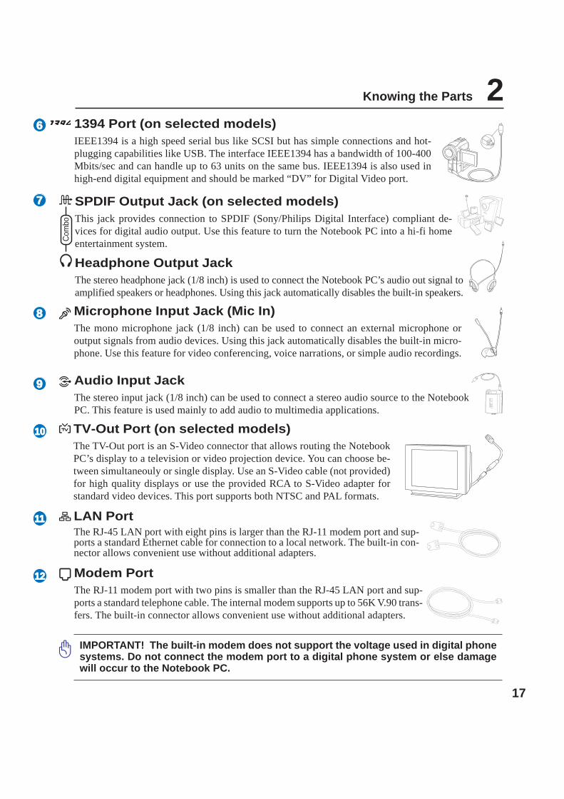
Microphone Input Jack (Mic In)The mono microphone jack (1/8 inch) can be used to connect an external microphone oroutput signals from audio devices. Using this jack automatically disables the built-in micro-phone. Use this feature for video conferencing, voice narrations, or simple audio recordings.
SPDIF Output Jack (on selected models)This jack provides connection to SPDIF (Sony/Philips Digital Interface) compliant de-vices for digital audio output. Use this feature to turn the Notebook PC into a hi-fi homeentertainment system.
Headphone Output JackThe stereo headphone jack (1/8 inch) is used to connect the Notebook PC’s audio out signal toamplified speakers or headphones. Using this jack automatically disables the built-in speakers.
Com
bo
6
7
8
1394 Port (on selected models)IEEE1394 is a high speed serial bus like SCSI but has simple connections and hot-plugging capabilities like USB. The interface IEEE1394 has a bandwidth of 100-400Mbits/sec and can handle up to 63 units on the same bus. IEEE1394 is also used inhigh-end digital equipment and should be marked “DV” for Digital Video port.
Modem PortThe RJ-11 modem port with two pins is smaller than the RJ-45 LAN port and sup-ports a standard telephone cable. The internal modem supports up to 56K V.90 trans-fers. The built-in connector allows convenient use without additional adapters.
IMPORTANT! The built-in modem does not support the voltage used in digital phonesystems. Do not connect the modem port to a digital phone system or else damagewill occur to the Notebook PC.
LAN PortThe RJ-45 LAN port with eight pins is larger than the RJ-11 modem port and sup-ports a standard Ethernet cable for connection to a local network. The built-in con-nector allows convenient use without additional adapters.
9 Audio Input JackThe stereo input jack (1/8 inch) can be used to connect a stereo audio source to the NotebookPC. This feature is used mainly to add audio to multimedia applications.
TV-Out Port (on selected models)The TV-Out port is an S-Video connector that allows routing the NotebookPC’s display to a television or video projection device. You can choose be-tween simultaneouly or single display. Use an S-Video cable (not provided)for high quality displays or use the provided RCA to S-Video adapter forstandard video devices. This port supports both NTSC and PAL formats.
1010
11
1212

18
2 Knowing the Parts
Left SideRefer to the diagram below to identify the components on this side of the Notebook PC.
1 2 3 4
Optical DriveThe Notebook PC comes in various models with different optical drives. The NotebookPC’s optical drive may support compact discs (CD) and/or digital video discs (DVD)and may have recordable (R) or re-writable (RW) capabilities. See the marketing speci-fications for details on each model.
1
2
3
4
Optical Drive Electronic EjectThe optical drive eject has an electronic eject button for opening the tray. You can also ejectthe optical drive tray through any software player or by right clicking the optical drive inWindows™ “My Computer.”
Optical Drive Emergency EjectThe emergency eject is used to eject the optical drive tray in case the electronic ejectdoes not work. Do not use the emergency eject in place of the electronic eject.
Stereo SpeakersThe built-in stereo speaker system allows you to hear audio without additional attachments. The multi-media sound system features an integrated digital audio controller that produces rich, vibrant sound(results improved with external stereo headphones or speakers). Audio features are software controlled.

19
Knowing the Parts 2Front SideRefer to the diagram below to identify the components on the front side of the Notebook PC.
1
2 43 2
1
2
Status Indicators (front)Status indicator details are described in section 3.
Display Panel LatchOne spring-loaded latch on the front of the Notebook PC locks the display panel in the closed positionwhen the Notebook PC is not in use. To open the display panel, negotiate the latch with your thumb andlift up the display panel while holding the latch. Slowly tilt the display panel forward or backward to acomfortable viewing angle.
WARNING! When opening, do not force the display panel down to the table or elsethe hinges may break! Never lift the Notebook PC by the display panel!
Stereo SpeakersThe built-in stereo speaker system allows you to hear audio without additional attachments. The multi-media sound system features an integrated digital audio controller that produces rich, vibrant sound(results improved with external stereo headphones or speakers). Audio features are software controlled.
CD Player Control Buttons (on selected models)There are several CD control buttons integrated externally on the Notebook PC for con-venient CD playing. The buttons activate and control your operating system’s softwareaudio player when the Notebook PC is ON. When your Notebook PC is OFF, the CDcontrol buttons activate a hardware CD player function that allows you to listen to audioCDs without software. (See section 3 for more information).
3
4

20
2 Knowing the Parts
Rear SideRefer to the diagram below to identify the components on this side of the Notebook PC.
1 2 43 5 6
2.0 USB Port (2.0/1.1)The Universal Serial Bus is compatible with USB 2.0 or USB 1.1 devices such askeyboards, pointing devices, cameras, hard disk drives, printers, and scanners con-nected in a series up to 12Mbits/sec (USB 1.1) and 480Mbits/sec (USB 2.0). USBallows many devices to run simultaneously on a single computer, with peripherals such as USB key-boards and some newer monitors acting as additional plug-in sites or hubs. USB supports hot-swappingof devices so that most peripherals can be connected or disconnected without restarting the computer.
1
3 Display (Monitor) OutputThe 15-pin D-sub output is an analog port that supports a standard VGA-compatible de-vice such as a monitor or projector to allow viewing on a larger external display.
Parallel PortThe 25-pin D-sub parallel/printer port supports native parallel devices such as laser/inkjetprinters, or parallel-adapted device such as external hard drives, removable drives, orscanners.
2
Dep
enid
ngon
mod
el.
Additional output ports (depending on model)
Display (DVI-D) OutputThe Digital Video Interface port is designed to maximize video graphics output to flatpanel LCD monitors or other DVI-compliant device.
DVI-D

21
Knowing the Parts 2Power (DC) InputThe supplied power adapter converts AC power to DC power for use with this jack.Power supplied through this jack supplies power to the Notebook PC and charges theinternal battery pack. To prevent damage to the Notebook PC and battery pack, al-ways use the supplied power adapter.
Kensington® Lock PortThe Kensington® lock port allows the Notebook PC to be secured using Kensington® com-patible Notebook PC security products. These security products usually include a metalcable and lock that prevent the Notebook PC to be removed from a fixed object. Somesecurity products may also include a motion detector to sound an alarm when moved.
6
Air VentsThe air vents allow cool air to enter and warm air to exit the Notebook PC.
IMPORTANT! Make sure that paper, books, clothing, cables, or other objects do notblock any of the air vents or else overheating of the Notebook PC may occur.
5
4

22
2 Knowing the Parts

23
3. Getting Started
Power System Using AC Power Using Battery Power Powering ON the Notebook PC Checking Battery Power Restarting or Rebooting Powering OFF the Notebook PCSpecial Keyboard FunctionsSwitches and Status Indicators

24
3 Getting Started
NOTE: This Notebook PC may come with either a two or three-prong plug depending onterritory. If a three-prong plug is provided, you must use a grounded AC outlet or use aproperly grounded adapter to ensure safe operation of the Notebook PC.
With the AC power cord connected to the AC-DC converter, connect the AC power cord to an AC outlet(preferably with surge-protection) and then connect the DC plug to the Notebook PC. Connecting theAC-DC adapter to the AC outlet first allows you to test the AC outlet’s power and the AC-DC converteritself for compatibility problems before connecting the DC power to the Notebook PC. The greenpower LED on the adapter lights up if the power is within accepted ranges.
TIP: You can buy travel kits for the Notebook PC that includes power and modemadapters for almost every country.
IMPORTANT! Damage may occur if you use a different adapter to power the Note-book PC or use the Notebook PC’s adapter to power other electrical devices. If thereis smoke, burning scent, or extreme heat coming from the AC-DC adapter, seek ser-vicing. Seek servicing if you suspect a faulty AC-DC adapter. You may damage bothyour battery pack(s) and the Notebook PC with a faulty AC-DC adapter.
Power System
Using AC PowerThe Notebook PC power is comprised of two parts, the power adapter and the battery power system.The power adapter converts AC power from a wall outlet to the DC power required by the NotebookPC. Your Notebook PC comes with a universal AC-DC adapter. That means that you may connect thepower cord to any 100V-120V as well as 220V-240V outlets without setting switches or using powerconverters. Different countries may require that an adapter be used to connect the provided US-stan-dard AC power cord to a different standard. Most hotels will provide universal outlets to support differ-ent power cords as well as voltages. It is always best to ask an experienced traveler about AC outletvoltages when bringing power adapters to another country.

25
Getting Started 3
2
1
Auto Lock
IMPORTANT! Never attempt to remove the battery pack while the Notebook PC isturned ON, as this may result in the loss of working data.
IMPORTANT! Only use battery packs and power adapters supplied with this Note-book PC or specifically approved by the manufacturer or retailer for use with thismodel or else damage may occur to the Notebook PC.
Using Battery PowerThe Notebook PC is designed to work with a removable battery pack. The battery pack consists of a setof battery cells housed together. A fully charged pack will provide several hours of battery life, whichcan be further extended by using power management features through the BIOS setup. Additionalbattery packs are optional and can be purchased separately through a Notebook PC retailer.
Installing and Removing the Battery PackYour Notebook PC may or may not have its battery pack installed. If your Notebook PC does not haveits battery pack installed, use the following procedures to install the battery pack.
Charging the Battery PackBefore you use your Notebook PC on the road, you will have to charge the battery pack. The batterypack begins to charge as soon as the Notebook PC is connected to external power using the poweradapter. Fully charge the battery pack before using it for the first time. A new battery pack must com-pletely charge before the Notebook PC is disconnected from external power. It takes a few hours tofully charge the battery when the Notebook PC is turned OFF and may take twice the time when theNotebook PC is turned ON. The battery charge light turns OFF when the battery pack is charged.
To install the battery pack: To remove the battery pack:
12
3

26
3 Getting Started
The Power-On Self Test (POST)When you turn ON the Notebook PC, it will first run through a series of software-controlled diagnostictests called the Power-On Self Test (POST). The software that controls the POST is installed as apermanent part of the Notebook PC’s architecture. The POST includes a record of the Notebook PC’shardware configuration, which is used to make a diagnostic check of the system. This record is createdby using the BIOS Setup program. If the POST discovers a difference between the record and theexisting hardware, it will display a message on the screen prompting you to correct the conflict byrunning BIOS Setup. In most cases the record should be correct when you receive the Notebook PC.When the test is finished, you may get a message reporting “No operating system found” if the harddisk was not preloaded with an operating system. This indicates that the hard disk is correctly detectedand ready for the installation of a new operating system.
The S.M.A.R.T. (Self Monitoring and Reporting Technology) checks the hard disk drive during POSTand gives a warning message if the hard disk drive requires servicing. If any critical hard disk drivewarning is given during bootup, backup your data immediately and run Windows disk checking program.To run Window’s disk checking program: (1) right-click any hard disk drive icon in “My Computer”, (2)choose Properties, (3) click the Tools tab, (4) click Check Now, (5) select a hard disk drive, (6) selectThorough to also check for physical damages, and (7) click Start. Third party disk utilities such as Symantec’sNorton Disk Doctor can also perform the same functions but with greater ease and more features.
Powering ON the Notebook PCThe Notebook PC’s power-ON message appears on the screen when you turn it ON. If necessary, you mayadjust the brightness by using the hot keys. If you need to run the BIOS Setup to set or modify the systemconfiguration, press [F2] upon bootup to enter the BIOS Setup. If you press [Tab] during the splashscreen, standard boot information such as the BIOS version can be seen. Press [ESC] and you will bepresented with a boot menu with selections to boot from your available drives.
NOTE: Before bootup, the display panel flashes when the power is turned ON. This ispart of the Notebook PC’s test routine and is not a problem with the display.
IMPORTANT! If warnings are still given during bootup after running a software diskchecking utility, you should take your Notebook PC in for servicing. Continued usemay result in data loss.
IMPORTANT! To protect the hard disk drive, always wait at least 5 seconds afterturning OFF your Notebook PC before turning it back ON.

27
Getting Started 3Checking Battery PowerThe battery system implements the Smart Battery standard underthe Windows environment, which allows the battery to accuratelyreport the amount of charge left in the battery. A fully-charged bat-tery pack provides the Notebook PC a few hours of working power.But the actual figure varies depending on how you use the powersaving features, your general work habits, the CPU, system memorysize, and the size of the display panel.
To check the remaining battery power, move your cursor over thepower icon. The power icon is a “battery” when not using AC powerand a “plug” when using AC power. Double click on the icon formore information and settings.
NOTE: You will be warned when battery power is low. If youcontinue to ignore the low battery warnings, the Notebook PCeventually enters suspend mode (Windows default uses STR).
WARNING! Suspend-to-RAM (STR) does not last long when the battery power is depleted.Suspend-to-Disk (STD) is not the same as power OFF. STD requires a small amount ofpower and will fail if no power is available due to complete battery depletion or no powersupply (e.g. removing both the power adapter and battery pack).
Battery CareThe Notebook PC’s battery pack, like all rechargeable batteries, has a limit on the number times it canbe recharged. Fully draining and charging the battery once a day every day will last over a year but howlong beyond that will depend on your environment temperature, humidity, and how your Notebook PCis used. It is ideal that the battery be used in a temperature range between 10˚C and 29˚C (50˚F and85˚F). You must also take into account that the Notebook PC’s internal temperature is higher than theoutside temperature. Any temperatures above or below this range will shorten the life of the battery.But in any case, the battery pack’s usage time will eventually decrease and a new battery pack must bepurchased from an authorized dealer for this Notebook PC. Because batteries also have a shelf life, it isnot recommended to buy extras for storing.
NOTE: The battery stops charging if the temperature is too high or the battery voltage istoo high. BIOS provides a smart battery refreshing function.
Move your mouse over the battery iconfor remaining power information.
When the AC power is connected,charging status will be shown.
Right-click the battery icon forsub-menus.
Left-click the battery icon for powermanagement settings.
WARNING! Do not leave the battery pack discharged. The battery pack will discharge overtime. If not using a battery pack, it must continued to be charged every three months orelse it may fail to charge in the future.
Note: Screen captures shown hereare examples only and may not re-flect what you see in your system.

28
3 Getting Started
Restarting or RebootingAfter making changes to your operating system, youmay be prompted to restart the system. Some instal-lation processes will provide a dialog box to allowrestart. To restart the system manually, click WindowsStart button and select Shut Down and then chooseRestart.
Powering OFFIn Windows XP, power OFF the Notebook PC by click-ing Windows Start button and select Shut Down andthen choose Turn off (or Shut down). For operatingsystems without proper power management (DOS,Windows NT), you must close all applications and exit operating systems and then power OFF by holdingthe power switch for 2 seconds (as opposed to 1 second to power ON). Holding the power switch for 2seconds is necessary in order to prevent accidental power-OFFs.
IMPORTANT! To protect the hard drive, wait at least 5 seconds after turning OFF yourNotebook PC before turning it back ON.
(Screens are different depending on security settings.)
Emergency ShutdownIn case your operating system cannot properly turn OFF or restart, there are two additional ways toshutdown your Notebook PC:
(1) Hold the power button over 4 seconds, or (2) Press the shutdown button .
TIP: Use a straightened paper clip topress the shutdown button.
IMPORTANT! Do not use emergency shutdown while data is being written; doing socan result in loss or destruction of your data.
(4 sec)
29
Getting Started 3Special Keyboard Functions
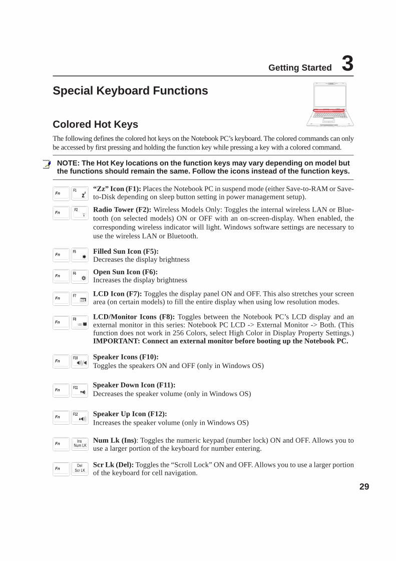
Colored Hot KeysThe following defines the colored hot keys on the Notebook PC’s keyboard. The colored commands can onlybe accessed by first pressing and holding the function key while pressing a key with a colored command.
NOTE: The Hot Key locations on the function keys may vary depending on model butthe functions should remain the same. Follow the icons instead of the function keys.
F1 “Zz” Icon (F1): Places the Notebook PC in suspend mode (either Save-to-RAM or Save-to-Disk depending on sleep button setting in power management setup).
F5 Filled Sun Icon (F5):Decreases the display brightness
F6 Open Sun Icon (F6):Increases the display brightness
F7 LCD Icon (F7): Toggles the display panel ON and OFF. This also stretches your screenarea (on certain models) to fill the entire display when using low resolution modes.
F8 LCD/Monitor Icons (F8): Toggles between the Notebook PC’s LCD display and anexternal monitor in this series: Notebook PC LCD -> External Monitor -> Both. (Thisfunction does not work in 256 Colors, select High Color in Display Property Settings.)IMPORTANT: Connect an external monitor before booting up the Notebook PC.
Num Lk (Ins): Toggles the numeric keypad (number lock) ON and OFF. Allows you touse a larger portion of the keyboard for number entering.
Scr Lk (Del): Toggles the “Scroll Lock” ON and OFF. Allows you to use a larger portionof the keyboard for cell navigation.
F12 Speaker Up Icon (F12):Increases the speaker volume (only in Windows OS)
Radio Tower (F2): Wireless Models Only: Toggles the internal wireless LAN or Blue-tooth (on selected models) ON or OFF with an on-screen-display. When enabled, thecorresponding wireless indicator will light. Windows software settings are necessary touse the wireless LAN or Bluetooth.
F2
F10 Speaker Icons (F10):Toggles the speakers ON and OFF (only in Windows OS)
Speaker Down Icon (F11):Decreases the speaker volume (only in Windows OS)
F11

30
3 Getting Started
Keyboard as a Numeric KeypadThe numeric keypad is embedded in the keyboard and con-sists of 15 keys that make number intensive input more con-venient. These dual-purpose keys are labeled in orange onthe key caps. Numeric assignments are located at the upperright hand corner of each key as shown in the figure. When
the numeric keypad is engaged by pressing , thenumber lock LED lights up. If an external keyboard is con-nected, pressing the on the external keyboard enables/disables the NumLock on both keyboards simultaneously.To disable the numeric keypad while keeping the keypad on an external keyboard activated, press the
keys on the Notebook PC.
Microsoft Windows™ KeysThere are two special Windows™ keys on the keyboard as described below.
The key with the Windows™ Logo activates the Start menu located at the bottom left of theWindows™ desktop.
The other key, that looks like a Windows™ menu with a small cursor, activates the propertiesmenu and is equivalent to pressing the right mouse button on a Windows™ object.
Keyboard as CursorsThe keyboard can be used as cursors while Number Lock isON or OFF in order to increase navigation ease while en-tering numeric data in spreadsheets or similar applications.
With Number Lock OFF, press and one of the cursorkeys shown below. For example [Fn][8] for up, [Fn][K] fordown, [Fn][U] for left, and [Fn][O] for right.
With Number Lock ON, use [Shift] and one of the cursorkeys shown below. For example [Shift][8] for up, [Shift][K]for down, [Shift][U] for left, and [Shift][O] for right.
NOTE: The arrow symbols are illustrated here for your reference. They are not labeledon the keyboard as shown here.

31
Getting Started 3
Switches
Switches and Status Indicators
Power4 Gear KeyThe Power4 Gear button toggles power savings between various power saving modes. The power sav-ing modes control many aspects of the Notebook PC to maximize performance versus battery timeduring various events.
When you are using an AC power adapter, Power4 Gear will switch between three modes in the ACpower mode segment. When you remove the AC adapter, Power4 Gear will switch between sevenmodes in the battery (DC) mode segment. When you remove or apply the AC adapter, Power4 Gear willautomatically shift you up or down into the proper mode segment (AC or DC).
SuperPerformance
HighPerformance
GamePerformance
DVD MoviePerformance
Email/OfficePerformance
PresentationPerformance
Audio ListeningPerformance
Battery-SavingPerformance
ModeNames
TaskbarIcons
AC AC/DC AC/DC DC DC DC DC DCPowerSegment
Email Launch KeyPressing this button will launch your Email application while Windows is running.
Internet Launch KeyPressing this button will launch your Internet browser application while Windows is running.
Pad-Lock KeyPressing this button will lock your touchpad when using an external mouse. Locking the touchpad willprevent you from accidentally moving the cursor while typing. To enable the touchpad, simply pressthis button again.
POWERThe power switch allows powering ON and OFF the Notebook PC and recovering from STD (Save-To-Disk). Push the switch once to turn ON and once to turn OFF the Notebook PC.

32
3 Getting Started
Status Indicators
Battery Charge IndicatorThe battery charge indicator is an LED that shows the status of the battery’s power as follows:ON: When turned ON or OFF - The Notebook PC’s battery is charging when AC power is connected.Off: The Notebook PC’s battery is charged or completely drained.Blinking: When turned ON - battery power is less than 10% and the AC power is not connected.
Drive Activity IndicatorIndicates that the Notebook PC is accessing one or more storage device(s) such as the hard disk. Thelight flashes proportional to the access time.
Front
Wireless LAN Indicator (on selected models)This indicator is only applicable on models with built-in wireless LAN. When the built-in wireless LANis enabled, this indicator will light. (Windows software settings are necessary to use the wireless LAN.)
Power IndicatorThis indicator lights to indicate that the Notebook PC is turned ON and blinks slowly when the Note-book PC is in the Suspend-to-RAM (Standby) mode. This indicator is OFF when the Notebook PC isOFF or in the Suspend-to-Disk (Hibernation) mode.
Top
Scroll LockIndicates that scroll lock [Scr Lk] is activated when lit. Scroll lock allows some of the keyboard lettersto act as direction keys in order to allow easier navigation when only a part of the keyboard is required,such as for playing games.
Email IndicatorFlashes when there is one or more new email(s) in your email program’s inbox. This function requiressoftware setup and may not be currently configured on your Notebook PC. This function is designedfor Microsoft email software only and may not work with email software from other companies.
Number LockIndicates that number lock [Num Lk] is activated when lighted. Number lock allows some of the key-board letters to act as numbers for easier numeric data input.
Capital LockIndicates that capital lock [Caps Lock] is activated when lighted. Capital lock allows some of thekeyboard letters to type using capitalized letters (e.g. A, B, C). When the capital lock light is OFF, thetyped letters will be in the lower case form (e.g. a,b,c).

33
Getting Started 3
CD Play/PauseDuring CD stop, begins CD play.During CD play, pauses CD play.
CD StopDuring CD stop: Ejects the CD tray.During CD play: Stops CD play.
CD Skip to Previous Track (Rewind) & Audio Volume DownDuring CD play, this button has two functions:
Track: The first push will restart the current track. The second push will skip to the previous track.Audio: Hold down to decrease audio volume.
CD Skip to Next Track (Fast Forward) & Audio Volume UpDuring CD play, this button has two functions:
Track: Push once to skip to the next track during CD playing.Audio: Hold down to increase audio volume.
CD Power SwitchWhile the Notebook PC is OFF: Turns ON or OFF the CD player.
Audio Volume Controls
Fn + Speaker Icons (F10): Toggles the audio volume ON and OFF
Fn + Down Speaker Icon (F11): Decreases the audio volume
Fn + Up Speaker Icon (F12): Increases the audio volume
CD Player Control Buttons and Indicator (on selected models)There are several CD control buttons integrated externally on the Notebook PC for convenient CDplaying. The buttons activate and control your operating system’s audio player when the Notebook PCis ON. When your Notebook PC is OFF, the CD control buttons activate a CD player function thatallows you to listen to audio CDs even while the Notebook PC is not turned ON. The following definesthe meaning of each CD control button and indicator on the front of the Notebook PC.

34
3 Getting Started

35
4. Using the Notebook PC
Operating SystemPointing DeviceStorage Devices PC Card (PCMCIA) Socket Optical Drive Hard Disk DriveConnections Modem Connection Network Connection IR Wireless Communication Bluetooth Wireless Connection Wireless LAN ConnectionPower Management Modes

36
4 Using the Notebook PC
Operating SystemThis Notebook PC may offer (depending on territory) its customers the choice of a pre-installed operatingsystem such as Microsoft Windows XP. The choices and languages will depend on the territory. Thelevels of hardware and software support may vary depending on the installed operating system. Thestability and compatibility of other operating systems cannot be guaranteed.
Support SoftwareThis Notebook PC comes with a support CD that provides BIOS,drivers and applications to enable hardware features, extendfunctionality, help manage your Notebook PC, or add functionalitynot provided by the native operating system. If updates orreplacement of the support CD is necessary, contact your dealerfor web sites to download individual software drivers and utilities.
The support CD contains all drivers, utilities and software for all popular operating systems includingthose that have been pre-installed. The support CD does not include the operating system itself. Thesupport CD is necessary even if your Notebook PC came pre-configured in order to provide additionalsoftware not included as part of the factory pre-install.
A recovery CD is optional and includes an image of the original operating system installed on the harddrive at the factory. The recovery CD provides a comprehensive recovery solution that quickly restoresthe Notebook PC’s operating system to its original working state provided that your hard disk drive isin good working order. Contact your retailer if you require such a solution.
Note: Some of the Notebook PC’s components and features may not work until thedevice drivers and utilities are installed.
OS
Models with Sonoma chipsetNotebook PC models with the Sonoma chipset willautomatically disable the Notebook PC’s touchpadwhen an external USB mouse is attached. To turn OFFthis feature, deselect the option in Windows ControlPanel - Mouse Properties - Device Settings.
37
Using the Notebook PC 4
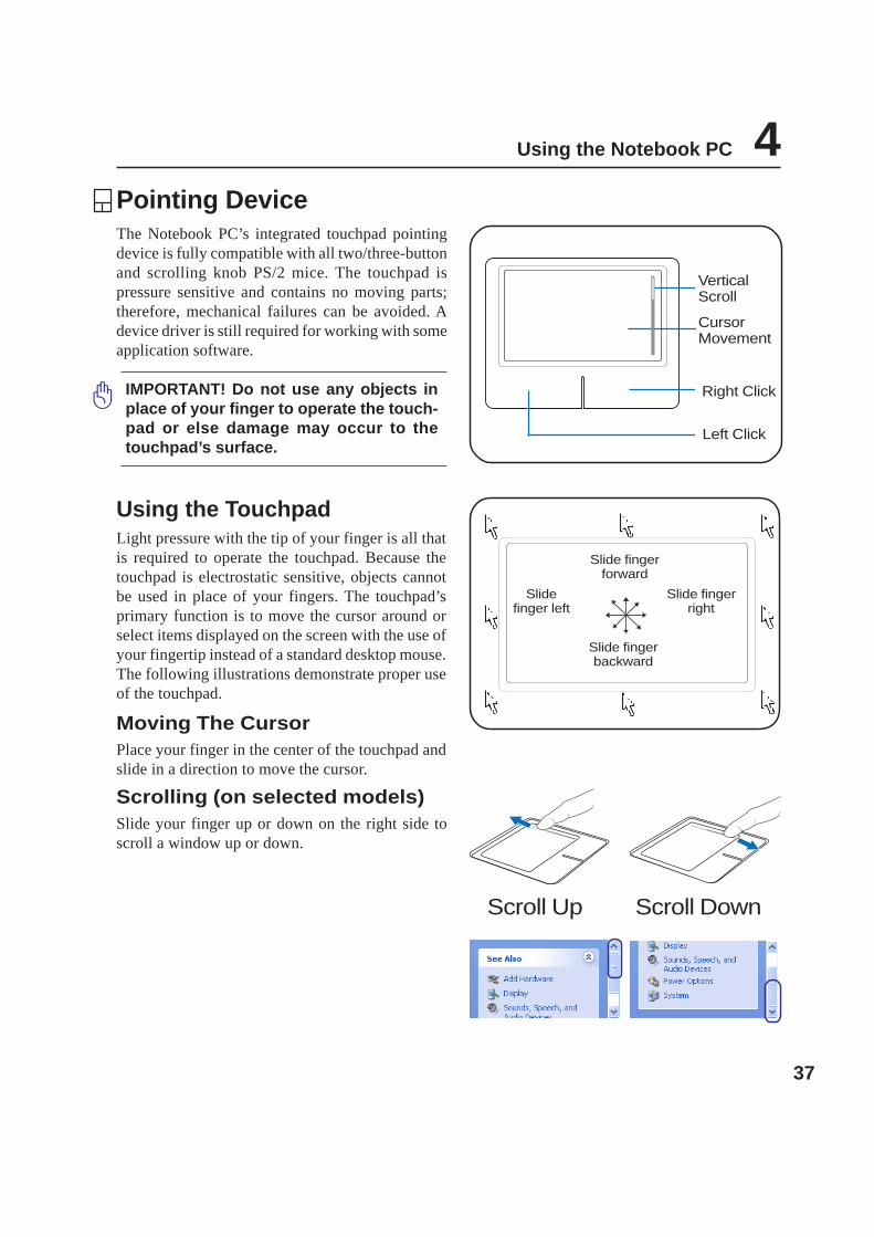
IMPORTANT! Do not use any objects inplace of your finger to operate the touch-pad or else damage may occur to thetouchpad’s surface.
Pointing DeviceThe Notebook PC’s integrated touchpad pointingdevice is fully compatible with all two/three-buttonand scrolling knob PS/2 mice. The touchpad ispressure sensitive and contains no moving parts;therefore, mechanical failures can be avoided. Adevice driver is still required for working with someapplication software.
Using the TouchpadLight pressure with the tip of your finger is all thatis required to operate the touchpad. Because thetouchpad is electrostatic sensitive, objects cannotbe used in place of your fingers. The touchpad’sprimary function is to move the cursor around orselect items displayed on the screen with the use ofyour fingertip instead of a standard desktop mouse.The following illustrations demonstrate proper useof the touchpad.
Moving The CursorPlace your finger in the center of the touchpad andslide in a direction to move the cursor.
Slide fingerforward
Slidefinger left
Slide fingerbackward
Slide fingerright
Scroll DownScroll Up
Scrolling (on selected models)Slide your finger up or down on the right side toscroll a window up or down.
CursorMovement
Right Click
Left Click
VerticalScroll

38
4 Using the Notebook PC
Double-clicking/Double-tapping - This is a common skill for launching a program directly from thecorresponding icon you select. Move the cursor over the icon you wish to execute, press the left buttonor tap the pad twice in rapid succession, and the system launches the corresponding program. If theinterval between the clicks or taps is too long, the operation will not be executed. You can set thedouble-click speed using the Windows Control Panel “Mouse.” The following 2 examples produce thesame results.
(press the left button twice and release) (lightly but rapidly strike the touchpad twice)
(press the left cursor button and release) (lightly but rapidly strike the touchpad)
Clicking/Tapping - With the cursor over an item, press the left button or use your fingertip to touch thetouchpad lightly, keeping your finger on the touchpad until the item is selected. The selected item willchange color. The following 2 examples produce the same results.
Clicking Tapping
Double-Clicking Double-Tapping
Touchpad Usage Illustrations

39
Using the Notebook PC 4
Caring for the TouchpadThe touchpad is pressure sensitive. If not properly cared for, it can be easily damaged. Take note of thefollowing precautions.
• Make sure the touchpad does not come into contact with dirt, liquids or grease.• Do not touch the touchpad if your fingers are dirty or wet.• Do not rest heavy objects on the touchpad or the touchpad buttons.• Do not scratch the touchpad with your finger nails or any hard objects.
Dragging - Dragging means to pick up an item and place it anywhere on the screen you wish. You canmove the cursor over the item you select, and while keeping the left button depressed, moving thecursor to the desired location, then release the button. Or, you can simply double-tap on the item andhold while dragging the item with your fingertip. The following illustrations produce the same results.
(hold left button and slide finger on touchpad) (lightly strike the touchpad twice, sliding fingeron touchpad during second strike)
Dragging-Clicking Dragging-Tapping
NOTE: A software-controlled scrolling function is available after setting up the includedtouchpad utility to allow easy Windows or web navigation. Basic functions can be ad-justed at the Windows control panel to allow comfortable clicking and tapping.
NOTE: The touchpad responds to movement not to force. There is no need to tap thesurface too hard. Tapping too hard does not increase the responsiveness of the touch-pad. The touchpad responds best to light pressure.

40
4 Using the Notebook PC
Storage DevicesStorage devices allow the Notebook PC to read or write documents, pictures, and other files to variousdata storage devices. This Notebook PC has the following storage devices:
• PC card
• Optical drive
• Hard disk drive
PC Card (PCMCIA) SocketThe Notebook PC supports PC Cards (or sometimes referred to as PCMCIA cards) to allow expansionlike PCI cards on desktop computers. This allows you to customize your Notebook PC to meet a widerange of application needs. The PCMCIA socket can interface with type I or type II PC cards. PC cardsare about the size of a few stacked credit cards and have a 68-pin connector at one end. The PC Cardstandard accommodates a number of function, communication, and data storage expansion options. PCcards come in memory/flash cards, fax/modems, networking adapters, SCSI adapters, MPEG I/II decodercards, Smart Cards, and even wireless modem or LAN cards. The Notebook PC supports PCMCIA 2.1,and 32-bit CardBus standards.
The three different PC Card standards actually have different thicknesses. Type I cards are 3.3mm,Type II cards are 5mm, and Type III cards are 10.5mm thick. Type I and Type II cards can be used in asingle socket and Type III cards take up two sockets. Type III cards are only supported on NotebookPC’s with two PC card sockets.
32-bit CardBus SupportCardBus support allows PC Cards and their hosts to use 32-bit bus mastering and operate at speeds ofup to 33MHz, transferring data in burst modes comparable with PCI’s 132MB/sec. By comparison, thestandard 16-bit PC Card bus can handle only 20MB/sec. Since the Notebook PC is equipped withCardBus broader and faster data pathway, it can handle bandwidth-hungry operations, such as 100MbpsFast Ethernet, Fast SCSI peripherals, and ISDN-based video conference. The CardBus peripherals supportplug and play.
The CardBus socket is backward-compatible with 16-bit PC Cards serving at 5 volts operation whileCardBus operates at 3.3 volts to reduce power consumption.

41
Using the Notebook PC 4Inserting a PC Card (PCMCIA)
1. Press in the toggle eject button and release.The recessed spring loaded toggle button willextend when pushed in and released.
2. Press the extended button again to eject the PCCard. Carefully pull the ejected PC card out ofthe socket.
Removing a PC Card (PCMCIA)To remove the PC card, first remove all cables or adapters attached to the PC card, then double-click thePC card icon on the Windows taskbar and stop the PC card you want to remove.
1
2
Be sure the PC card islevel when inserting.
3. Carefully connect any cables or adaptersneeded by the PC card. Usually connectors canonly be inserted in one orientation. Look for asticker, icon, or marking on one side of the con-nector representing the top side.
1. If there is a PC Card socket protector, remove itusing the “Removing a PC Card” instructionsbelow.
2. Insert the PC card with the connector side firstand label side up. Standard PC cards will beflush with the ASUS Notebook PC when fullyinserted.

42
4 Using the Notebook PC
Optical DriveInserting an optical disc
1. While the Notebook PC’s power is ON,press the drive’s eject button and the traywill eject out partially.
2. Gently pull on the drive’s front panel and slidethe tray completely out. Be careful not to touchthe CD drive lens and other mechanisms.Make sure there are no obstructions that mayget jammed under the drive’s tray.
3. Hold the disc by the edge and face the disc’sprinted side up. Push down on both sides ofthe disc’s center until the disc snaps ontothe hub. The hub should be higher thanthe disc when correctly mounted.
4. Slowly push the drive’s tray back in. The drivewill begin reading the table of contents (TOC)on the disc. When the drive stops, the disc isready to be used.
NOTE: It is normal to hear as well as feel the CD spinning with great intensity in theCD drive while data is read.

43
Using the Notebook PC 4
A CD drive letter should be present regardless of the presence of a CD disc in the drive. After the CD isproperly inserted, data can be accessed just like with hard disk drives; except that nothing can be written toor changed on the CD. Using the proper software, a CD-RW drive or DVD+CD-RW drive can allow CD-RW discs to be used like a hard drive with writing, deleting, and editing capabilities.
Vibration is normal for all high-speed optical drives due to unbalanced CDs or CD print. To decrease vibration,use the Notebook PC on an even surface and do not place labels on the CD.
Listening to Audio CDThe optical drives can play audio CDs, but only the DVD-ROM drive can play DVD audio. Insert the audioCD and Windows™ automatically opens an audio player and begins playing. Depending on the DVD audiodisc and installed software, it may require that you open a DVD player to listen to DVD audio. You canadjust the volume using hotkeys or Windows™ speaker icon on the taskbar.
Using the Optical DriveOptical discs and equipment must be handled with care because of the precise mechanics involved. Keep inmind the important safety instructions from your CD suppliers. Unlike desktop optical drives, the NotebookPC uses a hub to hold the CD in place regardless of the angle. When inserting a CD, it is important that theCD be pressed onto the center hub or else the optical drive tray will scratch the CD.
Optical Drive (Cont’)Removing an optical disc
Eject the tray and gently pry the edge of the discupwards at an angle to remove the disc from thehub.
The emergency eject is located in a hole on theoptical drive and is used to eject the optical drivetray in case the electronic eject does not work. Donot use the emergency eject in place of the electroniceject. Note: Make sure not to stab the activityindicator located in the same area.
Emergency eject
Actual location willvary by model.
WARNING! If the CD disc is not properly locked onto the center hub, the CD can bedamaged when the tray is closed. Always watch the CD closely while closing the trayslowly to prevent damage.

44
4 Using the Notebook PC
Flash Memory Card ReaderNormally a PCMCIA memory card reader must be purchased separately in order to use memory cardsfrom devices such as digital cameras, MP3 players, mobile phones, and PDAs. This Notebook PC hasa single built-in memory card reader that can read the following flash memory cards: Secure Digital(SD), Multi-Media Card (MMC), Memory Stick (MS), Memory Stick Select (MS Select), MemoryStick Duo (with MS adapter), Memory Stick Pro, and Memory Stick Pro Duo (with MS Pro adapter).Memory Sticks may be standard or with MagicGate technology. The built-in memory card reader is notonly convenient, but also faster than most other forms of memory card readers because it utilizes thehigh-bandwidth PCI bus.
Hard Disk DriveHard disk drives have higher capacities and operate at much faster speedsthan floppy disk drives and optical drives. The Notebook PC comes witha replaceable 2.5” (6.35cm) wide and approximately .374” (.95cm) highIDE hard disk drive. Current IDE hard drives support S.M.A.R.T. (SelfMonitoring and Reporting Technology) to detect hard disk errors orfailures before they happen. Most Notebook PC models use PATA(Parallel ATA) hard drives, but selected models use SATA (Serial ATA) hard drives. When replacing orupgrading the hard drive, always visit an authorized service center or retailer for this Notebook PC.
IMPORTANT! Poor handling of the Notebook PC may damage the hard disk drive.Handle the Notebook PC gently and keep it away from static electricity and strongvibrations or impact. The hard disk drive is the most delicate component and willlikely be the first or only component that is damaged if the Notebook PC is dropped.
MS (Memory Stick)Duo/Pro/Duo Pro/MG
MS (Memory Stick)Select
MS (Memory Stick)Magic Gate (MG)
MS (Memory Stick)
MS adapter
MMC (Multimedia Card)SD (Secure Digital)
Supported Memory Types
IMPORTANT! Never remove cards while or immediately after reading, copying, for-matting, or deleting data on the card or else data loss may occur.
SD / MMC
MS / MS Pro

45
Using the Notebook PC 4
CAUTION: For electrical safety concerns, only use telephone cables rated 26AWG orhigher. (see Glossary for more information)
NOTE: When you are connected to an online service, do not place the Notebook PC insuspend (or sleep mode) or else you will disconnect the modem connection.
WARNING! Only use analog telephone outlets. The built-in modem does not supportthe voltage used in digital phone systems. Do not connect the RJ-11 to digital phonesystems found in many commercial buildings or else damage will occur!
Modem ConnectionThe telephone wire used to connect the Notebook PC’s internalmodem should have either two or four wires (only two wires(telephone line #1) is used by the modem) and should have anRJ-11 connector on both ends. Connect one end to the modemport and the other end to an analog telephone wall socket (theones found in residential buildings). Once the driver is setup,the modem is ready to use.
TelephoneWall JackTelephone cables
with RJ-11 connectors
Telephoneconnection isoptional
Telephone connector isthe smaller of the two.
Example of the Notebook PC connected to a telephone jack for use with the built-in modem:

46
4 Using the Notebook PC
NOTE: The built-in modem and network cannot be installed later as an upgrade. Afterpurchase, modem and/or network can be installed as a PC card (PCMCIA).
Example of the Notebook PC connected to a Network Hub or Switch for use with the built-inEthernet controller.
Network ConnectionConnect a network cable, with RJ-45 connectors on each end, to the modem/network port on the NotebookPC and the other end to a hub or switch. For 100 BASE-TX / 1000 BASE-T speeds, your network cablemust be category 5 or better (not category 3) with twisted-pair wiring. If you plan on running theinterface at 100/1000Mbps, it must be connected to a 100 BASE-TX / 1000 BASE-T hub (not a BASE-T4 hub). For 10Base-T, use category 3, 4, or 5 twisted-pair wiring. 10/100 Mbps Full-Duplex is supportedon this Notebook PC but requires connection to a network switching hub with “duplex” enabled. Thesoftware default is to use the fastest setting so no user-intervention is required.
1000BASE-T (or Gigabit) is only supported on selected models.
Twisted-Pair CableThe cable used to connect the Ethernet card to a host (generallya Hub or Switch) is called a straight-through Twisted Pair Ethernet(TPE). The end connectors are called RJ-45 connectors, whichare not compatible with RJ-11 telephone connectors. If connectingtwo computers together without a hub in between, a crossoverLAN cable is required (Fast-Ethernet model). (Gigabit modelssupport auto-crossover so a crossover LAN cable is optional.)
Network Hub or Switch
Network cable withRJ-45 connectors
LAN connector is thelarger of the two.

47
Using the Notebook PC 4
IMPORTANT! Disable the infrared communication when you are not using the IR forlong periods because the IR consumes a great deal of Windows resources which willdecrease the Notebook PC’s performance.
(Windows XP)
IR Wireless Communication (on selected models)The Notebook PC is equipped with a conveniently located Infrared (IR) Communication Port (see 2.Knowing the Parts for location). The IR port comes with IrDA (Infrared Data Association) SerialInfrared Data Link Version 1.1 compliance, that allows you to perform point-to-point wirelesscommunications. You can use a IR-specified application to transmit or receive data files with othersystems equipped with an infrared port.
Guidelines for using IR communicationFollow the guidelines listed below when using the Infrared (IR) Communication:
• The angle between two Infrared communication ports should not exceed ±15˚.
• The distance between the Notebook PC’s IR and target device IR should not exceed 12 inches (30 cm).
• Do not move either the Notebook PC or the other device during transmission of data.
• An error may occur if IR transmission is conducted with high levels of noise or vibration.
• Avoid direct sunlight, flashing incandescent light, florescent light, and other infrared devices suchas remote controls close to the infrared port.
Enabling InfraredWindows infrared connection is called “Wireless Link” and should be enabled by default. Look for theicon in the Control Panel.

48
4 Using the Notebook PC
Add New Connection from theBluetooth taskbar icon
Bluetooth Settings from WindowsStart | Programs | Bluetooth
Click New Connection fromBluetooth Settings.
Follow the wizard to add Bluetoothdevices.
After complete, you should seeyour device in the window.
1
2
3
45
6
7 *#
8 0
9
g ptja
d m ? w
+a/A£t
£x£«
£⁄£¤
£‡£•
£ƒ£“
££„
£§£¶
£”
£¥£'
£·£‚
£|£¡£fl
£}£¢£
£u
£y£‹
£~££
£–£†
£v
£›£z
£{
£w£fi
Bluetooth Wireless Connection (on selected models)Notebook PCs with Bluetooth technology eliminates the need for cables for connecting Bluetooth-enabled devices. Examples of Bluetooth-enabled devices may be Notebook PCs, Desktop PCs, mobilephones, and PDAs.
Note: If your Notebook PC did not come with built-in Bluetooth, you need to connecta USB or PC Card Bluetooth module in order to use Bluetooth.
Bluetooth-enabled mobile phonesYou can wireless connect to your mobile phone. Depending on your mobile phone’scapabilities, you can transfer phone book data, photos, sound files, etc. or use it as amodem to connect to the Internet. You may also use it for SMS messaging.
Bluetooth-enabled computers or PDAsYou can wireless connect to another computer or PDA and exchange files, shareperipherals, or share Internet or network connections. You may also make use ofBluetooth-enabled wireless keyboard or mouse.
Pairing with Bluetooth-enabled devicesYou first need to pair your Notebook PC with a Bluetooth-enabled device before you canconnect to it. Make sure the Bluetooth-enabled device is turned ON and ready to accept apair. Launch Bluetooth Settings from Windows Start | Programs | Bluetooth or selectAdd New Connection from the Bluetooth taskbar icon if available.

49
Using the Notebook PC 4
These are examples of the NotebookPC connected to a Wireless Network.
Wireless LAN Connection (on selected models)The optional built-in wireless LAN is a compact easy-to-use wireless Ethernet adapter. Implementingthe IEEE 802.11 standard for wireless LAN (WLAN), the optional built-in wireless LAN is capable offast data transmission rates using Direct Sequence Spread Spectrum (DSSS) and Orthogonal FrequencyDivision Multiplexing (OFDM) technologies on 2.4 GHz frequencies. The optional built-in wirelessLAN is backward compatible with the earlier IEEE 802.11 standards allowing seamless interfacing ofwireless LAN standards.
The optional built-in wireless LAN is a client adapter that supports Infrastructure and Ad-hoc modesgiving you flexibility on your existing or future wireless network configurations for distances up to 40meters between the client and the access point.
To provide efficient security to your wireless communication, the optional built-in wireless LAN comeswith a 64-bit/128-bit Wired Equivalent Privacy (WEP) encryption and Wi-Fi Protected Access (WPA)features.
Infrastructure modeThe Infrastructure mode allows the Notebook PC andother wireless devices to join a wireless networkcreated by an Access Point (AP) (sold separately) thatprovides a central link for wireless clients tocommunicate with each other or with a wired network.
(All devices must install optional 802.11 wirelessLAN adapters.)
Ad-hoc modeThe Ad-hoc mode allows the Notebook PC to connectto another wireless device. No access point (AP) isrequired in this wireless environment.
(All devices must install optional 802.11 wirelessLAN adapters.)
Desktop PC
PDA
Notebook PC
AccessPoint
Desktop PC
PDA
Notebook PC
50
4 Using the Notebook PC
Power Management ModesThe Notebook PC has a number of automatic or adjustable power saving features that you can use tomaximize battery life and lower Total Cost of Ownership (TCO). You can control some of these featuresthrough the Power menu in the BIOS Setup. ACPI power management settings are made through theoperating system. The power management features are designed to save as much electricity as possibleby putting components into a low power consumption mode as often as possible but also allow fulloperation on demand. These low power modes are referred to as “Stand by” (or Suspend-to-RAM) and“Hibernation” mode or Suspend-to-Disk (STD). The Standby mode is a simple function provided bythe operating system. When the Notebook PC is in either one of the power saving modes, the status willbe shown by the following: “Stand by”: Power LED Blinks and “Hibernation”: Power LED OFF.
Full Power Mode & Maximum PerformanceThe Notebook PC operates in Full Power mode when the power management function is disabled byconfiguring Windows power management and SpeedStep. When the Notebook PC is operating in FullPower Mode, the Power LED remains ON. If you are conscious of both system performance and powerconsumption, select “Maximum Performance” instead of disabling all power management features.
ACPIAdvanced Configuration and Power Management (ACPI) was developed by Intel, Microsoft, and Toshibaespecially for Windows and later to control power management and Plug and Play features. ACPI is thenew standard in power management for Notebook PCs.
NOTE: APM was used in older operating systems like Windows NT4 and Windows 98.Because newer operating systems like Windows XP, Windows 2000, and Windows MEutilize ACPI, APM is no longer fully supported on this Notebook PC.
Suspend ModeIn “Stand by” (STR) and “Hibernation” (STD), the CPU clock is stopped and most of the Notebook PCdevices are put in their lowest active state. The suspend mode is the lowest power state of the NotebookPC. The Notebook PC enters suspend mode when the system remains idle for a specified amount of timeor manually using the [Fn][F1] keys. The Power LED blinks when the Notebook PC is in STR mode. InSTD mode, the Notebook PC will appear to be powered OFF. Recover from STR by pressing anykeyboard button (except Fn). Recover from STD by using the power switch (just like poweringON the Notebook PC).
Power SavingsIn addition to reducing the CPU clock, this mode puts devices including the LCD backlight in theirlower active state. The Notebook PC enters “Stand by” mode (low priority) when the system remainsidle for a specified amount of time. The timeout can be set through Windows power management (higherpriority). To resume system operation, press any key.

51
Using the Notebook PC 4Power State Summary
STATE ENTRY EVENT EXIT EVENT“Stand by” • “Stand by” through Windows Start button, • Any device
• Timer as set though “Power Management” • Battery low
in Windows Control Panel (higher priority)
STR (“Stand by”) • Hotkey [Fn][F1] • Signal from modem port(Suspend-to-RAM) -- • Power button • Any key
STD (“Hibernate”) • Hotkey [Fn][F1] • Power button
(Suspend-to-Disk) -- • Battery Extremely Low
Soft OFF • Power button (can be defined as STR or STD) • Power button
• “Shut down” through Windows Start button
Thermal Power ControlThere are three power control methods for controlling the Notebook PC’s thermal state. These powercontrol cannot be configured by the user and should be known in case the Notebook PC should enterthese states. The following temperatures represent the chassis temperature (not CPU).
• The fan turns ON for active cooling when the temperature reaches the safe upper limit.
• The CPU decreases speed for passive cooling when the temperature exceeds the safe upper limit.
• The system shut down for critical cooling when temperature exceeds the maximum safe upper limit.
52
4 Using the Notebook PC
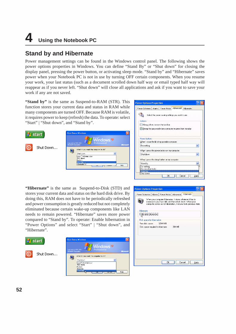
Stand by and HibernatePower management settings can be found in the Windows control panel. The following shows thepower options properties in Windows. You can define “Stand By” or “Shut down” for closing thedisplay panel, pressing the power button, or activating sleep mode. “Stand by” and “Hibernate” savespower when your Notebook PC is not in use by turning OFF certain components. When you resumeyour work, your last status (such as a document scrolled down half way or email typed half way willreappear as if you never left. “Shut down” will close all applications and ask if you want to save yourwork if any are not saved.
“Stand by” is the same as Suspend-to-RAM (STR). Thisfunction stores your current data and status in RAM whilemany components are turned OFF. Because RAM is volatile,it requires power to keep (refresh) the data. To operate: select“Start” | “Shut down”, and “Stand by”.
“Hibernate” is the same as Suspend-to-Disk (STD) andstores your current data and status on the hard disk drive. Bydoing this, RAM does not have to be periodically refreshedand power consumption is greatly reduced but not completelyeliminated because certain wake-up components like LANneeds to remain powered. “Hibernate” saves more powercompared to “Stand by”. To operate: Enable hibernation in“Power Options” and select “Start” | “Shut down”, and“Hibernate”.

53
Appendix
Optional AccessoriesOptional ConnectionsGlossaryDeclarations and Safety StatementsNotebook PC Information

54
A Appendix
Optional AccessoriesThese items, if desired, come as optional items to complement your Notebook PC.
USB Hub (Optional)Attaching an optional USB hub will increase yourUSB ports and allow you to quickly connect ordisconnect many USB peripherals through a singlecable.
USB 2.0 Slim Combo Drive (Optional)The slim combo drive features FlextraLink™ (anti-coaster technology) and FlextraSpeed™ (recordingtechnology) to help prevent writing unusable discs, minimizes CPU loading to allow operation of othersoftware while writing, and automatically adjust for optimal recording speed versus vibration to reducerotational noise.
• Interface: USB 2.0• Data buffer: 2MB (write), 512KB (read)• Disc sizes: 12cm and 8cm• DVD (read): 8X max• CD (read): 24X max• CD-R (write): 24X, 20X, 16X, 8X, 4X• CD-RW (write): 12X, 10X, 8X, 4X, 2X• Dimensions: 16mm x 129mm x 142mm• Weight: 250g• (Specifications may change without notice.)
USB Flash Memory DiskA USB flash memory disk is an optional item thatcan replace the 1.44MB floppy disk and provide stor-age up to several hundred megabytes, higher trans-fer speeds, and greater durability. When used in cur-rent operating systems, no drivers are necessary.
USB Communication CableAttaching optional USB communication cables between computers throughthe USB ports will allow basic file transfer capabilities between the comput-ers whether they be Notebook PC’s, Desktop PC’s, or a combination of both.

55
Appendix AOptional Accessories (Cont.)These items, if desired, come as optional items to complement your Notebook PC.
Wireless LAN CardThe ASUS WLAN PC Card (WL-107g) is a wireless LAN adapter that fits into a PCMCIAType II slot in a Notebook PC and creates a wireless network using the IEEE 802.11g/bwireless standards.
802.11g 54Mbps
Wireless LAN USB AdapterThe ASUS USB Wireless LAN Adapter (WL-167g) is thumb-sized andcreates a wireless network using the IEEE 802.11g/b wireless standardsand connects to any computer using USB2.0 connectivity.
USB Keyboard and MouseAttaching an external USB keyboard will allow data entry to bemore comfortable. Attaching an external USB mouse will allowWindows navigation to be more comfortable. Both the externalUSB keyboard and mouse will work simultaneously with the Note-book PC’s built-in keyboard and touchpad.
WARNING! To prevent system failures, use (Safely Remove Hard-ware) on the taskbar before disconnecting the USB floppy disk drive. Eject the floppydisk before transporting the Notebook PC to prevent damage from shock.
USB Floppy Disk DriveThe Notebook PC features an optional USB-interface disk drive that accepts astandard 1.44MB (or 720KB) 3.5-inch floppy diskette. The eject button is onthe top edge of the floppy disk drive for easy access, unlike desktop PCs withthe eject button on the bottom of the floppy disk drive. Floppy access activitycan be monitored through the LED on the front of the floppy disk drive.

56
A Appendix
Optional Connections (Cont.)These items, if desired, may be purchased from third-parties.
Printer ConnectionOne or more USB printers can be simultaneously used on any USB portor USB hub.

57
Appendix AGlossaryACPI (Advanced Configuration and Power Management Interface)Modern standard for reducing power usage in computers.
APM (Advanced Power Management)Modern standard for reducing power usage in computers.
AWG (American Wire Gauge)
NOTE: This table is for general reference only and should not be used as a source ofthe American Wire Gauge standard as this table may not be current or complete.
Gauge Diam Area R I@3A/mm2
AWG (mm) (mm2) (ohm/km) (mA)
33 0.18 0.026 676 75
0.19 0.028 605 85
32 0.20 0.031 547 93
30 0.25 0.049 351 147
29 0.30 0.071 243 212
27 0.35 0.096 178 288
26 0.40 0.13 137 378
25 0.45 0.16 108 477
Gauge Diam Area R I@3A/mm2
AWG (mm) (mm2) (ohm/km) (mA)
24 0.50 0.20 87.5 588
0.55 0.24 72.3 715
0.60 0.28 60.7 850
22 0.65 0.33 51.7 1.0 A
0.70 0.39 44.6 1.16 A
0.75 0.44 38.9 1.32 A
20 0.80 0.50 34.1 1.51 A
0.85 0.57 30.2 1.70 A
BIOS (Basic Input/Output System)BIOS is a set of routines that affect how the computer transfers data between computer components,such as memory, disks, and the display adapter. The BIOS instructions are built into the computer’sread-only memory. BIOS parameters can be configured by the user through the BIOS Setup program.The BIOS can be updated using the provided utility to copy a new BIOS file into the EEPROM.
Bit (Binary Digit)Represents the smallest unit of data used by the computer. A bit can have one of two values: 0 or 1.
BootBoot means to start the computer operating system by loading it into system memory. When the manualinstructs you to “boot” your system (or computer), it means to turn ON your computer. “Reboot” meansto restart your computer. When using Windows 95 or later, selecting “Restart” from “Start | Shut Down...”will reboot your computer.
Bluetooth (on selected models)Bluetooth is a short-range wireless technology that lets you connect computers, mobile phones, andhandheld devices to each other and to the Internet. Bluetooth technology eliminates the ned for thecables that connect devices together. Bluetooth-enabled devices connect wirelessly within a 10 m range.

58
A Appendix
Byte (Binary Term)One byte is a group of eight contiguous bits. A byte is used to represent a single alphanumeric character,punctuation mark, or other symbol.
Clock ThrottlingChipset function which allows the processor’s clock to be stopped and started at a known duty cycle.Clock throttling is used for power savings, thermal management, and reducing processing speed.
CPU (Central Processing Unit)The CPU, sometimes called “Processor,” actually functions as the “brain” of the computer. It interpretsand executes program commands and processes data stored in memory.
Device DriverA device driver is a special set of instructions that allows the computer’s operating system to commu-nicate with devices such as VGA, audio, Ethernet, printer, or modem.
DVDDVD is essentially a bigger, faster CD that can hold video as well as audio and computer data. Withthese capacities and access rates, DVD discs can provide you with dramatically-enhanced high-color,full-motion videos, better graphics, sharper pictures, and digital audio for a theater-like experience.DVD aims to encompass home entertainment, computers, and business information with a single digi-tal format, eventually replacing audio CD, videotape, laserdisc, CD-ROM, and video game cartridges.
HardwareHardware is a general term referring to the physical components of a computer system, including pe-ripherals such as printers, modems, and pointing devices.
IDE (Integrated Drive Electronics)IDE devices integrate the drive control circuitry directly on the drive itself, eliminating the need for aseparate adapter card (in the case for SCSI devices). UltraDMA/66 or 100 IDE devices can achieve upto 33MB/Sec transfer.
IEEE1394 (1394)Also known as iLINK (Sony) or FireWire (Apple). 1394 is a high speed serial bus like SCSI but hassimple connections and hot-plugging capabilities like USB. The popular 1394a interface has a band-width of 400Mbits/sec and can handle up to 63 units on the same bus. The newer 1394b interface cansupport twice the speed and will appear in future models when peripherals support higher speeds. It isvery likely that 1394, together with USB, will replace Parallel, IDE, SCSI, and EIDE ports. 1394 is alsoused in high-end digital equipment and should be marked “DV” for Digital Video port.
Infrared Port (IrDA) (on selected models)The infrared (IrDA) communication port allows convenient wireless data communication with infra-red-equipped devices or computers up to 4Mbits/sec. This allows easy wireless synchronization withPDAs or mobile phones and even wireless printing to printers. Small offices can use IrDA technologyto share a printer between several closely placed Notebok PCs and even send files to each other withouta network.

59
Appendix AKensington® LocksKensington® locks (or compatible) allow the Notebok PC to be secured usually using a metal cable andlock that prevent the Notebok PC to be removed from a fixed object. Some security products may alsoinclude a motion detector to sound an alarm when moved.
Laser ClassificationsAs lasers became more numerous and more widely used, the need to warn users of laser hazards becameapparent. To meet this need, laser classifications were established. Current classification levels vary fromoptically safe, requiring no controls (Class 1) to very hazardous, requiring strict controls (Class 4).
CLASS 1: A Class 1 laser or laser system emits levels of optical energy that are eye-safe and conse-quently require no controls. An example of this class of laser system is the checkout scanning devicefound in most grocery stores or lasers used in optical drives.
CLASS 2 & CLASS 3A: Class 2 and Class 3A lasers emit visible, continuous-wave (CW) opticalradiation levels slightly above the maximum permissible exposure (MPE) level. Although these laserscan cause eye damage, their brightness usually causes observers to look away or blink before eyedamage occurs. These lasers have strict administrative controls requiring placement of signs warningpersonnel not to stare directly into the beam. Class 3A lasers must not be viewed with optically-aideddevices.
CLASS 3B: Class 3B lasers, and Class 3A lasers with outputs of 2.5mW, are hazardous to personnelwho are within the beam path and look at the beam source directly or by specular reflection. Theselasers cannot produce hazardous diffuse reflections. Personnel working with these lasers should wearappropriate protective eyewear during any operation of the laser. Class 3B lasers have both adminis-trative and physical controls to protect personnel. Physical controls include limited access work areas.Administrative controls include special warning signs posted outside the entrances to the laser workspaces and lights outside the entrances that warn personnel when the lasers are in use.
CLASS 4: Class 4 lasers are high-power lasers that will cause damage to unprotected eyes and skinthrough intra-beam viewing and specular or diffuse reflections. Consequently, no personnel should bein aroom where a Class 4 laser is operating without proper eye protection.
PCI Bus (Peripheral Component Interconnect Local Bus)PCI bus is a specification that defines a 32-bit data bus interface. PCI is a standard widely used byexpansion card manufacturers.
PC Cards (PCMCIA)PC cards are about the size of a few stacked credit cards and have a 68-pin connector at one end. ThePC Card standard accommodates a number of function, communication, and data storage expansionoptions. PC cards come in memory/flash cards, fax/modems, networking adapters, SCSI adapters, MPEGI/II decoder cards, and even wireless modem or LAN cards. The Notebok PC supports PCMCIA 2.1,and 32bit CardBus standards. The three different PC Card standards actually have different thicknesses.Type I cards are 3.3mm, Type II cards are 5mm, and Type III cards are 10.5mm thick. Type I and TypeII cards can be used in a single socket. Type III cards take up two sockets and must be used on NotebokPCs with two sockets.

60
A Appendix
POST (Power On Self Test)When you turn on the computer, it will first run through the POST, a series of software-controlleddiagnostic tests. The POST checks system memory, the motherboard circuitry, the display, the key-board, the diskette drive, and other I/O devices.
RAM (Random Access Memory)There are several different types of RAM such as DDR (Double Dynamic RAM), DRAM (DynamicRAM), EDO DRAM (Extended Data Output DRAM), SDRAM (Synchronous DRAM).
ROM (Read Only Memory)ROM is nonvolatile memory used to store permanent programs (called firmware) used in certain com-puter components. Flash ROM (or EEPROM) can be reprogrammed with new programs (or BIOS).
Suspend ModeIn Save-to-RAM (STR) and Save-to-Disk (STD), the CPU clock is stopped and most of the NotebookPC devices are put in their lowest active state. The Notebook PC enters Suspend when the systemremains idle for a specified amount of time or manually using the function keys. The timeout setting ofboth Hard Disk and Video can be set by the BIOS Setup. The Power LED blinks when the Notebook PCis in STR mode. In STD mode, the Notebook PC will appear to be powered OFF.
System DiskA system disk contains the core file of an operating system and is used to boot up the operating system.
TPM (Trusted Platform Module) (on selected models)The TPM is a security hardware device on the system board that will hold computer-generated keys forencryption. It is a hardware-based solution that can help avoid attacks by hackers looking to capturepasswords and encryption keys to sensitive data. The TPM provides the ability to the PC or notebook torun applications more secure and to make transactions and communication more trustworthy.
Twisted-Pair CableThe cable used to connect the Ethernet card to a host (generally a Hub or Switch) is called a straight-through Twisted Pair Ethernet (TPE). The end connectors are called RJ-45 connectors, which are notcompatible with RJ-11 telephone connectors. If connecting two computers together without a hub inbetween, a crossover twisted-pair is required.
UltraDMA/66 or 100UltraDMA/66 or 100 are new specifications to improve IDE transfer rates. Unlike traditional PIOmode, which only uses the rising edge of IDE command signal to transfer data, UltraDMA/66 or 100uses both rising edge and falling edge.
USB (Universal Serial Bus)A new 4-pin serial peripheral bus that allows plug and play computer peripherals such as keyboard,mouse, joystick, scanner, printer and modem/ISDN to be automatically configured when they are at-tached physically without having to install drivers or reboot. With USB, the traditional complex cablesfrom back panel of your PC can be eliminated.

61
Appendix ADeclarations and Safety Statements
DVD-ROM Drive InformationThe Notebook PC comes with an optional DVD-ROM drive or a CD-ROM drive. In order to viewDVD titles, you must install your own DVD viewer software. Optional DVD viewer software may bepurchased with this Notebook PC. The DVD-ROM drive allows the use of both CD and DVD discs.
Regional Playback InformationPlayback of DVD movie titles involves decoding MPEG2 video, digital AC3 audio and decryption of CSSprotected content. CSS (sometimes called copy guard) is the name given to the content protection schemeadopted by the motion picture industry to satisfy a need to protect against unlawful content duplication.
Although the design rules imposed on CSS licensors are many, one rule that is most relevant is playbackrestrictions on regionalized content. In order to facilitate geographically staggered movie releases, DVDvideo titles are released for specific geographic regions as defined in “Region Definitions” below. Copyrightlaws require that all DVD movies be limited to a particular region (usually coded to the region at which it issold). While DVD movie content may be released for multiple regions, CSS design rules require that anysystem capable of playing CSS encrypted content must only be capable of playing one region.
Region DefinitionsRegion 1Canada, US, US Territories
Region 2Czech, Egypt, Finland, France, Germany, Gulf States, Hungary, Iceland, Iran, Iraq, Ireland, Italy, Ja-pan, Netherlands, Norway, Poland, Portugal, Saudi Arabia, Scotland, South Africa, Spain, Sweden,Switzerland, Syria, Turkey, UK, Greece, Former Yugoslav Republics, Slovakia
Region 3Burma, Indonesia, South Korea, Malaysia, Philippines, Singapore, Taiwan, Thailand, Vietnam
Region 4
Australia, Caribbean (Except US Territories), Central America, New Zealand, Pacific Islands, SouthAmerica
Region 5
CIS, India, Pakistan, Rest of Africa, Russia, North Korea
Region 6China
NOTE: The region setting may be changed up to five times using the viewer software,then it can only play DVD movies for the last region setting. Changing the region codeafter that will require factory resetting which is not covered by warranty. If resetting isdesired, shipping and resetting costs will be at the expense of the user.

62
A Appendix
Internal Modem CompliancyThe Notebook PC with internal modem model complies with JATE (Japan), FCC (US, Canada, Korea,Taiwan), and CTR21. The internal modem has been approved in accordance with Council Decision 98/482/EC for pan-European single terminal connection to the public switched telephone network (PSTN).However due to differences between the individual PSTNs provided in different countries, the approvaldoes not, of itself, give an unconditional assurance of successful operation on every PSTN networktermination point. In the event of problems you should contact your equipment supplier in the firstinstance.
OverviewOn 4th August 1998 the European Council Decision regarding the CTR 21 has been published in theOfficial Journal of the EC. The CTR 21 applies to all non voice terminal equipment with DTMF-dialling which is intended to be connected to the analogue PSTN (Public Switched Telephone Net-work).
CTR 21 (Common Technical Regulation) for the attachment requirements for connection to the ana-logue public switched telephone networks of terminal equipment (excluding terminal equipment sup-porting the voice telephony justified case service) in which network addressing, if provided, is bymeans of dual tone multifrequency signalling.
Network Compatibility DeclarationStatement to be made by the manufacturer to the Notified Body and the vendor: "This declaration willindicate the networks with which the equipment is designed to work and any notified networks withwhich the equipment may have inter-working difficulties"
Network Compatibility DeclarationStatement to be made by the manufacturer to the user: "This declaration will indicate the networks withwhich the equipment is designed to work and any notified networks with which the equipment mayhave inter-working difficulties. The manufacturer shall also associate a statement to make it clear wherenetwork compatibility is dependent on physical and software switch settings. It will also advise the userto contact the vendor if it is desired to use the equipment on another network."
Up to now the Notified Body of CETECOM issued several pan-European approvals using CTR 21. Theresults are Europe's first modems which do not require regulatory approvals in each individual Euro-pean country.
Non-Voice EquipmentAnswering machines and loud-speaking telephones can be eligible as well as modems, fax machines,auto-dialers and alarm systems. Equipment in which the end-to-end quality of speech is controlled byregulations (e.g. handset telephones and in some countries also cordless telephones) is excluded.

63
Appendix AInternal Modem Compliancy (Cont.)This table shows the countries currently under the CTR21 standard.
Country Applied More TestingAustria1 Yes NoBelgium Yes NoCzech Republic No Not ApplicableDenmark1 Yes YesFinland Yes NoFrance Yes NoGermany Yes NoGreece Yes NoHungary No Not ApplicableIceland Yes NoIreland Yes NoItaly Still Pending Still PendingIsrael No NoLichtenstein Yes NoLuxemburg Yes NoThe Netherlands1 Yes YesNorway Yes NoPoland No Not ApplicablePortugal No Not ApplicableSpain No Not ApplicableSweden Yes NoSwitzerland Yes NoUnited Kingdom Yes No
This information was copied from CETECOM and is supplied without liability. For updates to thistable, you may visit http://www.cetecom.de/technologies/ctr_21.html
1 National requirements will apply only if the equipment may use pulse dialling (manufacturers maystate in the user guide that the equipment is only intended to support DTMF signalling, which wouldmake any additional testing superfluous).
In The Netherlands additional testing is required for series connection and caller ID facilities.

64
A Appendix
(Reprinted from the Code of Federal Regulations #47, part 15.193, 1993. Washington DC: Office of theFederal Register, National Archives and Records Administration, U.S. Government Printing Office.)
Canadian Department of Communications StatementThis digital apparatus does not exceed the Class B limits for radio noise emissions from digital apparatusset out in the Radio Interference Regulations of the Canadian Department of Communications.
This Class B digital apparatus complies with Canadian ICES-003.
(Cet appareil numérique de la classe B est conforme à la norme NMB-003 du Canada.)
CE Mark WarningThis is a Class B product, in a domestic environment, this product may cause radio interference, inwhich case the user may be required to take adequate measures.
WARNING! The use of a shielded-type power cord is required in order to meet FCCemission limits and to prevent interference to the nearby radio and television recep-tion. It is essential that only the supplied power cord be used. Use only shieldedcables to connect I/O devices to this equipment. You are cautioned that changes ormodifications not expressly approved by the party responsible for compliance couldvoid your authority to operate the equipment.
Federal Communications Commission StatementThis device complies with FCC Rules Part 15. Operation is subject to the following two conditions:
• This device may not cause harmful interference, and
• This device must accept any interference received, including interference that may cause undesired operation.
This equipment has been tested and found to comply with the limits for a class B digital device, pursuantto Part 15 of the Federal Communications Commission (FCC) rules. These limits are designed to providereasonable protection against harmful interference in a residential installation. This equipment generates,uses, and can radiate radio frequency energy and, if not installed and used in accordance with the instruc-tions, may cause harmful interference to radio communications. However, there is no guarantee that inter-ference will not occur in a particular installation. If this equipment does cause harmful interference toradio or television reception, which can be determined by turning the equipment off and on, the user isencouraged to try to correct the interference by one or more of the following measures:
• Reorient or relocate the receiving antenna.
• Increase the separation between the equipment and receiver.
• Connect the equipment into an outlet on a circuit different from that to which the receiver is connected.
• Consult the dealer or an experienced radio/TV technician for help.

65
Appendix AFCC Radio Frequency Interference RequirementsMPE Statement: Your device contains a low power transmitter. When device is transmitted it sends outRadio Frequency (RF) signal.
This device is restricted to INDOOR USE due to its operation in the 5.15 to 5.25GHz frequency range. FCCrequires this product to be used indoors for the frequency range 5.15 to 5.25GHz to reduce the potential forharmful interference to co-channel of the Mobile Satellite Systems.
High power radars are allocated as primary user of the 5.25 to 5.35GHz and 5.65 to 5.85GHz bands. Theseradar stations can cause interference with and / or damage this device.
This device and its antenna(s) must not be co-located or operating in conjunction with any other antenna ortransmitter.
FCC RF Exposure Guidelines (Wireless Clients)This device has been tested for compliance with FCC RF Exposure (SAR) limits in typical portableconfigurations. In order to comply with SAR limits established in the ANSI C95.1 standards, it is recommendedwhen using a wireless LAN adapter that the integrated antenna is positioned more than [20cm] from yourbody or nearby persons during extended periods of operation. If the antenna is positioned less than [20cm]from the user, it is recommended that the user limit the exposure time.
FCC Radio Frequency Exposure Caution StatementInstallation and use of this wireless LAN device must be in strict accordance with the instructions includedin the documentation provided with the product. Use only with the supplied antenna. Unauthorized antenna,modification, or attachments could damage the transmitter and may violate FCC regulations. Any changesor modifications (including the antennas) made to this device that are not expressly approved by themanufacturer may void the user’s authority to operate the equipment.
The manufacturer is not responsible for any radio or television interference caused by unauthorizedmodification of this device, or the substitution or attachment of connecting cables and equipment other thanmanufacturer specified. It is the responsibility of the user to correct any interference caused by suchunauthorized modification, substitution or attachment. Manufacturer and its authorized resellers or distributorswill assume no liability for any damage or violation of government regulations arising from failing to complywith these guidelines.
Declaration of Conformity (R&TTE directive 1999/5/EC)The following items were completed and are considered relevant and sufficient:• Essential requirements as in [Article 3]• Protection requirements for health and safety as in [Article 3.1a]• Testing for electric safety according to [EN 60950]• Protection requirements for electromagnetic compatibility in [Article 3.1b]• Testing for electromagnetic compatibility in [EN 301 489-1] & [EN 301]• Testing according to [489-17]• Effective use of the radio spectrum as in [Article 3.2]• Radio test suites according to [EN 300 328-2]

66
A Appendix
France Restricted Wireless Frequency BandsSome areas of France have a restricted frequency band. The worst case maximum authorized power indoorsare:
• 10mW for the entire 2.4 GHz band (2400 MHz–2483.5 MHz)• 100mW for frequencies between 2446.5 MHz and 2483.5 MHz
NOTE: Channels 10 through 13 inclusive operate in the band 2446.6 MHz to 2483.5 MHz.
There are few possibilities for outdoor use: On private property or on the private property of public persons,use is subject to a preliminary authorization procedure by the Ministry of Defense, with maximum authorizedpower of 100mW in the 2446.5–2483.5 MHz band. Use outdoors on public property is not permitted.
In the departments listed below, for the entire 2.4 GHz band:
• Maximum authorized power indoors is 100mW• Maximum authorized power outdoors is 10mW
Departments in which the use of the 2400–2483.5 MHz band is permitted with an EIRP of less than 100mWindoors and less than 10mW outdoors:
01 Ain Orientales 02 Aisne 03 Allier 05 Hautes Alpes08 Ardennes 09 Ariège 11 Aude 12 Aveyron16 Charente 24 Dordogne 25 Doubs 26 Drôme32 Gers 36 Indre 37 Indre et Loire 41 Loir et Cher45 Loiret 50 Manche 55 Meuse 58 Nièvre59 Nord 60 Oise 61 Orne 63 Puy du Dôme64 Pyrénées Atlantique 66 Pyrénées 67 Bas Rhin 68 Haut Rhin70 Haute Saône 71 Saône et Loire 75 Paris 82 Tarn et Garonne84 Vaucluse 88 Vosges 89 Yonne 90 Territoire de Belfort94 Val de Marne
This requirement is likely to change over time, allowing you to use your wireless LAN card in more areaswithin France. Please check with ART for the latest information (www.art-telecom.fr)
NOTE: Your WLAN Card transmits less than 100mW, but more than 10mW.
Wireless Operation Channel for Different DomainsN. America 2.412-2.462 GHz Ch01 through CH11Japan 2.412-2.484 GHz Ch01 through Ch14Europe ETSI 2.412-2.472 GHz Ch01 through Ch13

67
Appendix AUL Safety NoticesRequired for UL 1459 covering telecommunications (telephone) equipment intended to be electricallyconnected to a telecommunication network that has an operating voltage to ground that does not exceed200V peak, 300V peak-to-peak, and 105V rms, and installed or used in accordance with the NationalElectrical Code (NFPA 70).
When using the Notebook PC modem, basic safety precautions should always be followed to reducethe risk of fire, electric shock, and injury to persons, including the following:
• Do not use the Notebook PC near water, for example, near a bath tub, wash bowl, kitchen sink orlaundry tub, in a wet basement or near a swimming pool.
• Do not use the Notebook PC during an electrical storm. There may be a remote risk of electricshock from lightning.
• Do not use the Notebook PC in the vicinity of a gas leak.
Required for UL 1642 covering primary (nonrechargeable) and secondary (rechargeable) lithium bat-teries for use as power sources in products. These batteries contain metallic lithium, or a lithium alloy,or a lithium ion, and may consist of a single electrochemical cell or two or more cells connected inseries, parallel, or both, that convert chemical energy into electrical energy by an irreversible or revers-ible chemical reaction.
• Do not dispose the Notebook PC battery pack in a fire, as they may explode. Check with localcodes for possible special disposal instructions to reduce the risk of injury to persons due to fire orexplosion.
• Do not use power adapters or batteries from other devices to reduce the risk of injury to personsdue to fire or explosion. Use only UL certified power adapters or batteries supplied by the manu-facturer or authorized retailers.
Power Safety RequirementProducts with electrical current ratings up to 6A and weighing more than 3Kg must use approved powercords greater than or equal to: H05VV-F, 3G, 0.75mm2 or H05VV-F, 2G, 0.75mm2.

68
A Appendix
Nordic Cautions (for Notebook PC with Lithium-Ion Battery)CAUTION! Danger of explosion if battery is incorrectly replaced. Replace only with the same orequivalent type recommended by the manufacturer. Dispose of used batteries according to themanufacturer’s instructions. (English)
ATTENZIONE! Rischio di esplosione della batteria se sostituita in modo errato. Sostituire la batteria con ununa di tipo uguale o equivalente consigliata dalla fabbrica. Non disperdere le batterie nell’ambiente. (Italian)
VORSICHT! Explosionsgetahr bei unsachgemäßen Austausch der Batterie. Ersatz nur durch denselbenoder einem vom Hersteller empfohlenem ähnlichen Typ. Entsorgung gebrauchter Batterien nach Angabendes Herstellers. (German)
ADVARSELI! Lithiumbatteri - Eksplosionsfare ved fejlagtig håndtering. Udskiftning må kun ske medbatteri af samme fabrikat og type. Levér det brugte batteri tilbage til leverandøren. (Danish)
VARNING! Explosionsfara vid felaktigt batteribyte. Använd samma batterityp eller en ekvivalent typsom rekommenderas av apparattillverkaren. Kassera använt batteri enligt fabrikantens instruktion. (Swedish)
VAROITUS! Paristo voi räjähtää, jos se on virheellisesti asennettu. Vaihda paristo ainoastaan laitevalmistajansousittelemaan tyyppiin. Hävitä käytetty paristo valmistagan ohjeiden mukaisesti. (Finnish)
ATTENTION! Il y a danger d’explosion s’il y a remplacement incorrect de la batterie. Remplaceruniquement avec une batterie du mêre type ou d’un type équivalent recommandé par le constructeur.Mettre au rebut les batteries usagées conformément aux instructions du fabricant. (French)
ADVARSEL! Eksplosjonsfare ved feilaktig skifte av batteri. Benytt samme batteritype eller en tilsvarende typeanbefalt av apparatfabrikanten. Brukte batterier kasseres i henhold til fabrikantens instruksjoner. (Norwegian)
(Japanese)
69
Appendix A
Service warning label
WARNING: Making adjustments or performing procedures other than those specifiedin the user’s manual may result in hazardous laser exposure. Do not attempt to disas-semble the optical drive. For your safety, have the optical drive serviced only by anauthorized service provider.
CAUTION: INVISIBLE LASER RADIATION WHEN OPEN. DO NOT STARE INTO BEAMOR VIEW DIRECTLY WITH OPTICAL INSTRUMENTS.
CDRH RegulationsThe Center for Devices and Radiological Health (CDRH) of the U.S. Food and Drug Administrationimplemented regulations for laser products on August 2, 1976. These regulations apply to laser productsmanufactured from August 1, 1976. Compliance is mandatory for products marketed in the United States.
WARNING: Use of controls or adjustments or performance of procedures other thanthose specified herein or in the laser product installation guide may result in hazard-ous radiation exposure.
Macrovision Corporation Product NoticeThis product incorporates copyright protection technology that is protected by method claims of certainU.S.A. patents and other intellectual property rights owned by Macrovision Corporation and other rightsowners. Use of this copyright protection technology must be authorized by Macrovision Corporation, andis intended for home and other limited viewing uses only unless otherwise authorized by MacrovisionCorporation. Reverse engineering or disassembly is prohibited.
Optical Drive Safety Information
Laser Safety InformationInternal or external optical drives sold with this Notebook PC contains a CLASS 1 LASER PRODUCT.Laser classifications can be found in the glossary at the end of this user’s manual.

70
A Appendix
Danish
Dutch
English
Finnish
French
German
Greek
Italian
Portuguese
Spanish
Swedish
CTR 21 Approval (for Notebook PC with built-in Modem)

71
Appendix A

72
A Appendix
Notebook PC InformationThis page is provided for recording information concerning your Notebook PC for future reference orfor technical support. Keep this User’s Manual in a secured location if passwords are filled out.
Owner’s Name:____________________________ Owner’s Telephone: ______________
Manufacturer: _______________ Model: ___________ Serial Number: ______________
Display Size:____________ Resolution: _____________ Memory Size: ______________
Retailer: _________________Location: ___________ Purchase Date: ______________
Hard Drive Manufacturer: ____________________________ Capacity: ______________
Optical Drive Manufacturer: _____________________________ Type: ______________
BIOS Version: __________________________________________Date: ______________
Accessories: _____________________________________________________________
Accessories: _____________________________________________________________
SoftwareOperating System: __________Version: ___________ Serial Number: ______________
Software: _________________Version: ___________ Serial Number: ______________
Software: _________________Version: ___________ Serial Number: ______________
SecuritySupervisor Name: _______________________ Supervisor Password: ______________
User Name:___________________________________ User Password: ______________
NetworkUser Name:______________ Password: _________________ Domain: ______________
User Name:______________ Password: _________________ Domain: ______________

Copyright InformationNo part of this manual, including the products and software described in it, may be reproduced, transmitted, tran-scribed, stored in a retrieval system, or translated into any language in any form or by any means, except documen-tation kept by the purchaser for backup purposes, without the express written permission of ASUSTeK COM-PUTER INC. (“ASUS”).
ASUS PROVIDES THIS MANUAL “AS IS” WITHOUT WARRANTY OF ANY KIND, EITHER EXPRESS ORIMPLIED, INCLUDING BUT NOT LIMITED TO THE IMPLIED WARRANTIES OR CONDITIONS OF MER-CHANTABILITY OR FITNESS FOR A PARTICULAR PURPOSE. IN NO EVENT SHALL ASUS, ITS DIREC-TORS, OFFICERS, EMPLOYEES OR AGENTS BE LIABLE FOR ANY INDIRECT, SPECIAL, INCIDENTAL,OR CONSEQUENTIAL DAMAGES (INCLUDING DAMAGES FOR LOSS OF PROFITS, LOSS OF BUSI-NESS, LOSS OF USE OR DATA, INTERRUPTION OF BUSINESS AND THE LIKE), EVEN IF ASUS HASBEEN ADVISED OF THE POSSIBILITY OF SUCH DAMAGES ARISING FROM ANY DEFECT OR ERRORIN THIS MANUAL OR PRODUCT.
Product warranty or service will not be extended if: (1) the product is repaired, modified or altered, unless suchrepair, modification or alteration is authorized in writing by ASUS; or (2) the serial number of the product is defacedor missing.
Products and corporate names appearing in this manual may or may not be registered trademarks or copyrights oftheir respective companies, and are used only for identification or explanation and to the owners’ benefit, withoutintent to infringe.
SPECIFICATIONS AND INFORMATION CONTAINED IN THIS MANUAL ARE FURNISHED FOR INFOR-MATIONAL USE ONLY, AND ARE SUBJECT TO CHANGE AT ANY TIME WITHOUT NOTICE, AND SHOULDNOT BE CONSTRUED AS A COMMITMENT BY ASUS. ASUS ASSUMES NO RESPONSIBILITY OR LI-ABILITY FOR ANY ERRORS OR INACCURACIES THAT MAY APPEAR IN THIS MANUAL, INCLUDINGTHE PRODUCTS AND SOFTWARE DESCRIBED IN IT.
Copyright © 2005 ASUSTeK COMPUTER INC. All Rights Reserved.
Limitation of LiabilityCircumstances may arise where because of a default on ASUS’ part or other liability, you are entitled to recoverdamages from ASUS. In each such instance, regardless of the basis on which you are entitled to claim damages fromASUS, ASUS is liable for no more than damages for bodily injury (including death) and damage to real property andtangible personal property; or any other actual and direct damages resulted from omission or failure of performinglegal duties under this Warranty Statement, up to the listed contract price of each product.
ASUS will only be responsible for or indemnify you for loss, damages or claims based in contract, tort or infringe-ment under this Warranty Statement.
This limit also applies to ASUS’ suppliers and its reseller. It is the maximum for which ASUS, its suppliers, and yourreseller are collectively responsible.
UNDER NO CIRCUMSTANCES IS ASUS LIABLE FOR ANY OF THE FOLLOWING: (1) THIRD-PARTYCLAIMS AGAINST YOU FOR DAMAGES; (2) LOSS OF, OR DAMAGE TO, YOUR RECORDS OR DATA; OR(3) SPECIAL, INCIDENTAL, OR INDIRECT DAMAGES OR FOR ANY ECONOMIC CONSEQUENTIALDAMAGES (INCLUDING LOST PROFITS OR SAVINGS), EVEN IF ASUS, ITS SUPPLIERS OR YOUR RE-SELLER IS INFORMED OF THEIR POSSIBILITY.

Contact Information
ASUSTeK COMPUTER INC.Company address: 15 Li-Te Road, Beitou, Taipei 11259General (tel): +886-2-2894-3447 Web site address: www.asus.com.twGeneral (fax): +886-2-2894-7798 General email: [email protected]
Technical supportGeneral support (tel): +886-2-2894-3447 Online support: http://support.asus.com
ASUS COMPUTER INTERNATIONAL (America)Company address: 44370 Nobel Drive, Fremont, CA 94538, USAGeneral (fax): +1-510-608-4555 Web site address: usa.asus.com
Technical supportGeneral support (tel): +1-502-995-0883 Online support: http://support.asus.comNotebook (tel): +1-510-739-3777 x5110 Support (fax): +1-502-933-8713
ASUS COMPUTER GmbH (Germany & Austria)Company address: Harkort Str. 25, D-40880 Ratingen, GermanyGeneral (tel): +49-2102-95990 Web site address: www.asuscom.deGeneral (fax): +49-2102-959911 Online contact: www.asuscom.de/sales
Technical supportComponent support: +49-2102-95990 Online support: http://support.asus.comNotebook support: +49-2102-959910 Support (fax): +49-2102-959911