Embed Size (px)
Citation preview

Hardware User Manual(Manual Part Number MAN-UTIC-P, Revision 1)

ii
WARNING!Programmable control devices such as the ToughPanel must not be used as stand-alone protection inany application. Unless proper safeguards are used, unwanted start-ups could result in equipmentdamage or personal injury. The operator must be made aware of this hazard and appropriateprecautions must be taken.In addition, consideration must be given to the use of an emergency stop function that is independent ofthe programmable controller.The diagrams and examples in this user manual are included for illustrative purposes only. Themanufacturer cannot assume responsibility or liability for actual use based on the diagrams andexamples.
WARNING: If the ToughPanel is used in a CLASS I, DIV. 2 environment, the following conditions mustbe met: Class I, Div. 2 methods; AND — must conform to all rules and requirements of applicablejurisdictions regarding Class I, Div. 2 installations; ALSO — peripheral equipment controlling this deviceor being controlled by it shall be suitable for service in the location in which they are used. Failure tocomply with any of the above installation requirements will invalidate the device’s qualifications forservice in CLASS I, DIV. 2 hazardous locations.
WARNING: EXPLOSION HAZARD — SUBSTITUTION OF COMPONENTS MAY IMPAIRSUITABILITY FOR CLASS I, DIVISION 2.
WARNING: EXPLOSION HAZARD — DO NOT DISCONNECT EQUIPMENT UNLESS POWER HASBEEN SWITCHED OFF OR THE AREA IS KNOWN TO BE NON-HAZARDOUS.
CAUTIONDo not press the ToughPanel touchscreen with any sharp objects. This practice may damage the unitbeyond repair.TrademarksThis publication may contain references to products produced and/or offered by other companies. Theproduct and company names may be trademarked and are the sole property of their respective owners.UTICOR Technology, L. P. disclaims any proprietary interest in the marks and names of others.
Manual P/N MAN-UTIC-P, Revision 1, 08/08© Copyright 2008, UTICOR Technology, L.P.All Rights Reserved
No part of this manual shall be copied, reproduced, or transmitted in any way without the prior writtenconsent of UTICOR Technology, L.P. UTICOR Technology, L.P. retains the exclusive rights to all
information included in this document.MANUFACTURED and MARKETED by UTICOR TECHNOLOGY, L. P.
4140 Utica Ridge Rd. • Bettendorf, IA 52722-1327
Phone: 1-563-359-7501 • Fax: 1-563-359-9094 • www.UTICOR.net
iii
EU Compliance Information
The ToughPanel is manufactured in compliance with European Union (EU) Directives and carries theCE mark. The ToughPanel has been tested under CE Test Standard #EN55011, and is listed under ULFile #E209355. The following information is provided to comply with EU documentation requirements.
Please NOTE: Products with CE marks perform their required functions safely and adhere to relevantstandards as specified by EU directives provided they are used according to their intended purpose andthat the instructions in this manual are adhered to. The protection provided by the equipment may beimpaired if this equipment is not used in accordance with this manual. Only replacement parts suppliedby UTICOR Technology, L.P. or its agents should be used.
Technical SupportIf you need assistance, please call our technical support at 1-800-832-3647 or FAX us at1-563-359-9094.
SELV CircuitsAll electrical circuits connected to the communications port receptacle are rated as Safety Extra LowVoltage (SELV).
Environmental SpecificationsOperating Temperature:
4" Monochrome 0 to 40 °C4" Color 0 to 55 °C6" White on Blue 0 to 45 °C6" Color 0 to 55 °C8" Color 0 to 40 °C10" Color 0 to 50 °C15" Color 0 to 45 °C
Storage Temperature:All Models: –20 to +60 °C
Operating Humidity: 10–95% R.H., non-condensing
Air Composition: No corrosive gases permitted
Preventative Maintenance and Cleaning: No preventative maintenance is required. TheToughPanel touchscreen should be cleaned as needed with warm, soapy water. Please refer toChapter 5: Maintenance for a list of compatible/incompatible chemicals and compounds.
iv
Manual Revisions
Manual Part Number : MAN-UTIC-P Revision 1Manual Title : Tough Panel Hardware User Manual
The following table provides you with updated information. If you call technical support with a questionabout this manual, please be aware of the revision number and date.
Revision Author Date Effective Pages Description of Changes
Original Release EG/ECF September, 2008 All Original Release of Manual

v
Manual OrganizationThe information below provides an overall description of the topics covered within this manual.
Chapter 1: Getting StartedGeneral overview of the installation procedure; lists all the equipment you need to get started.Explains how to get help with installation questions or problems you might encounter throughOn-screen Help and Technical Support.
Chapter 2: Models and EquipmentOverview of Uticor part numbering system. Quick reference chart of all ToughPanel models andthe competitor units they replace, with internal document links for general specifications,dimensions, and panel cutout measurements. Lists the important features of all ToughPanelswith dedicated processors, and the PLC drivers they support by brand, model, and protocol.Descriptions of replacement parts & optional accessories available, including memory cards,PLC cables, and the programming cable.
Chapter 3: SpecificationsGeneral specifications and detailed information are given for each model, such as weights,dimensions, and service power requirements; operating and storage temperatures; memory andserial communication options, etc.
Chapter 4: InstallationOverview of the physical requirements for mounting in a NEMA4 rated enclosure or cabinet.Instructions for mounting with DIN brackets. Provides dimensional diagrams and cutoutmeasurements for each of the ToughPanel models. Identifies and defines all connectors onToughPanel units. Tells you how to properly connect the unit to power supply, programmingcomputer, printer, or a PLC. Shows the setup screens displayed after initial powerup of thepanel. Describes each setup screen and how to use it to set up your panel.
Chapter 5: MaintenanceProvides instructions on battery replacement, gasket replacement, memory upgrade (FLASHand RAM), Fuse Reset, and fluorescent backlight replacement. Discusses precautions andcleaning necessary to ensure longevity of the panel.
Chapter 6: Troubleshooting Aids in diagnosing problems you might encounter when installing or operating your ToughPanel.Provides steps to take to isolate and correct problems.
Appendix A: Wiring diagrams for several PLC cables are provided.
Appendix B: Option Card Installation instructions are provided.
vi
Table of ContentsWARNING! iiEU Compliance Information iiiManual Revisions ivManual Organization vChapter 1:Getting Started 1
1.1 Installing the ToughPanel – Overview 1 1.2 What You Need to Get Started 2
1.2.1 Hardware 2 1.2.2 Software 2 1.2.3 ToughPanel Manuals 2
1.3 Need Help? 3 1.3.1 On-screen Installation HELP 3 1.3.2 On-screen PLC HELP 3 1.3.3 Technical Support 3
Chapter 2:Models and Equipment 4 2.1 Introduction to the Uticor ToughPanels 4 2.2 ToughPanel Part Numbering System 5 2.3 ToughPanel Models – Installation Information 6 2.4 ToughPanel Features – All Models 7 2.5 PLCs Supported by Tough Panels 8
2.5.1 Universal Ethernet Drivers 9 2.5.2 High Speed Dedicated Network Drivers 9 2.5.3 Dual Drivers 9 2.5.4 NetView & Control 9
2.6 Optional Parts and Accessories 10 2.6.1 Cables 10 2.6.2 Other Parts & Accessories 11
Chapter 3:Unit Specifications 12 3.1 General Specifications for 4-inch ToughPanels 12 3.2 General Specifications for 6-inch Tough Panels 13 3.3 General Specifications for 8 and 10-inch Tough Panels 14 3.4 General Specifications for 10 and 15-inch ToughPanels 15
Chapter 4:Installation 16 4.1 Mounting Overview 16 4.2 DIN Bracket Mounting – Step by Step 17 4.3 4-inch ToughPanel Dimensions and Cutout Measurements 18 4.4 6-inch ToughPanel Dimensions and Cutout Measurements 18
4.4.1 6” Panel dimensions: PV550, PV600, & QP 6” models 18 4.4.2 6” Panel dimensions: PV700 models 19
4.5 8-inch ToughPanel Dimensions and Cutout Measurements 19 4.6 10-inch ToughPanel Dimensions and Cutout Measurements 20
4.6.1 10” Panel Dimensions: PV900, PVPlus1000, & QP 10” series 20 4.6.2 10” Panel Dimensions: PV1000 20 4.6.3 10” Panel Dimensions: PV1200 21
4.7 15-inch ToughPanel Dimensions and Cutout Measurements 21 4.8 Wiring and Connections 22
4.8.1 Standard ToughPanel with Dedicated Processor 22
vii
4.8.2 4-inch and smaller footprint 6-inch ToughPanels 25 4.9 Power Terminal 26 4.10 PLC Port 26 4.11 COM1 Port 27 4.12 Communications Setup 28
4.12.1 Setup Mode 28 4.12.2 Clock 28 4.12.3 COM1 29 4.12.4 Group & Unit 30 4.12.5 Contrast 30 4.12.6 Touchpad Test 31 4.12.7 Display Test 31 4.12.8 Entering & Exiting Setup Mode 31
Chapter 5:Maintenance 32 5.1 Shutting Off Power to ToughPanel 32 5.2 Program Backup to Disk 33 5.3 Lithium Battery Replacement 35 5.4 Panel Status Indicator Light 36 5.5 Gasket Replacement 36 5.6 RAM Upgrade 37 5.7 Flash Program Backup 39 5.8 Fuse Reset 40 5.9 Fluorescent Backlight Bulb Replacement 40 5.10 Precautions: 40 5.11 Touchscreen Chemical Compatibility 41 5.12 Touchscreen Cleaning 41
Chapter 6:Troubleshooting 42 6.1 Common Problems: 42
6.1.1 Problem: Panel won’t power up 42 6.1.2 Problem: Cannot communicate with ToughPanel from Programming Computer 42 6.1.3 Problem: Communications with PLC 42 6.1.4 Problem: Memory Card 43 6.1.5 Problem: Display Blank 43 6.1.6 Problem: Display hangs when unit is powered up, “Initializing...” message remainson screen (unit has invalid RAM memory) 43
6.2 Still Need Help? 44 6.2.1 Warranty Repairs 44 6.2.2 Out of Warranty Repairs 44
Appendix A:PLC Cable Wiring Diagrams 45Appendix B:Option Card Installation 57

CHAPTER 1: GETTING STARTED
1.1 Installing the ToughPanel – Overview
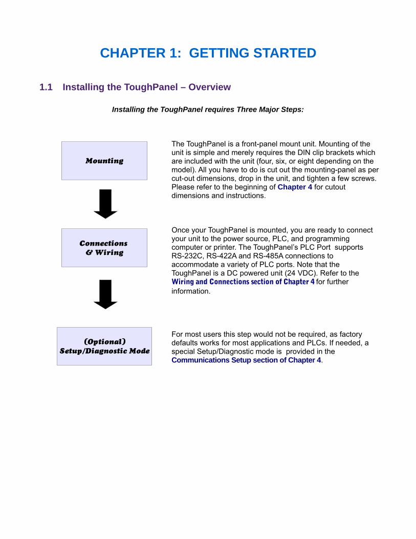
Installing the ToughPanel requires Three Major Steps:
The ToughPanel is a front-panel mount unit. Mounting of theunit is simple and merely requires the DIN clip brackets whichare included with the unit (four, six, or eight depending on themodel). All you have to do is cut out the mounting-panel as percut-out dimensions, drop in the unit, and tighten a few screws.Please refer to the beginning of Chapter 4 for cutoutdimensions and instructions.
Once your ToughPanel is mounted, you are ready to connectyour unit to the power source, PLC, and programmingcomputer or printer. The ToughPanel’s PLC Port supportsRS-232C, RS-422A and RS-485A connections toaccommodate a variety of PLC ports. Note that theToughPanel is a DC powered unit (24 VDC). Refer to theWiring and Connections section of Chapter 4 for furtherinformation.
For most users this step would not be required, as factorydefaults works for most applications and PLCs. If needed, aspecial Setup/Diagnostic mode is provided in theCommunications Setup section of Chapter 4.
Connections & Wiring
Mounting
(Optional)Setup/Diagnostic Mode
2 Chapter 1:Getting Started
1.2 What You Need to Get Started
1.2.1 Hardware
ToughPanel & enclosed mounting hardware (4, 6, or 8 DIN Clip Brackets, depending onsize of ToughPanel model)
24 Volt Power Supply, RS-232C Programming Cable (P/N CBL-UTICW-009) PLC Interface Cable as required.(see Page 10 for part numbers specific to your PLC
model), Ethernet cables as required PC requirements:
IBM or compatible PC (Pentium or better) with a mouse and separate serial port(USB port may be used with a Serial to USB converter)
Display with at least 800 x 600 resolution (1024 x 768 recommended) Standard Windows XP/Vista® operating system CD ROM Drive
uWin08 Programming Software
1.2.2 Software
ToughPanel uWin08 Software (P/N MAN-UTICW-CD) ToughPanel uWin08 Software User Manual (P/N MAN-UTIC-M)
1.2.3 ToughPanel Manuals
There are two manuals that you will need to use your ToughPanel; ToughPanel UTP Hardware User Manual (this manual) ToughPanel UTP uWin08 Software User Manual (P/N MAN-UTIC-M).
This ToughPanel UTP Hardware User Manual will give you all the information necessary toinstall the ToughPanel in a fixed location in your work environment, and how to wire it to yourPLC and to a programming device or network. Included are mounting diagrams for panelcutouts and instructions for installation with the enclosed DIN clip brackets, Connections andWiring requirements, Panel Setup instructions, Maintenance Information, andTroubleshooting.
Meanwhile, if you want to start designing your screens, you can do so off-line on a PC -- youcan install uWin08, the ToughPanel Programming Software, on a computer and design yourscreen(s) without any connection to a ToughPanel. The screen designs can be downloadedto the ToughPanel afterward, before or after the physical installation of the hardware! To setup the screens, please consult the ToughPanel UTP uWin08 Software User Manual (P/NMAN-UTIC-M).

Chapter 1:Getting Started 3
1.3 Need Help?
Help is never more than a mouse click or a key press away!
1.3.1 On-screen Installation HELP
In addition to this manual, Installation Guidelines and Diagrams can also be found in theHELP of uWin08, the ToughPanel Programming Software! To access these Help windows,click on "Help" in the Menu bar of the uWin08 Software, select "Help Topics", and then clickon the "Contents" tab. One of the topics displayed will be "Hardware Installation", and itcontains all the essential information needed, including dimensions, mounting instructions,connection and wiring setup, and more!
1.3.2 On-screen PLC HELP
You can also consult the uWin08 Software HELP if you need help with the PLC toToughPanel Interface, or any other communications or wiring issue. Each PLC Driver has aHelp Topic that lists the error messages and provides an explanation for each. Also providedare PLC to ToughPanel wiring diagrams.
1.3.3 Technical Support
Although most questions would be answered with this manual or the HELP within uWin08Software, if you are still having difficulty with a particular aspect of installation or screendesign, technical support is available at 1-800-TEC-ENGR (832-3647) or FAX us at1-563-359-9094. You can also visit our website at www.uticor.net.

CHAPTER 2: MODELS AND EQUIPMENT
2.1 Introduction to the Uticor ToughPanelsThe Uticor ToughPanel is a family of state-of-the art HMIs that combine all the latest advantages ofdigital control technology in a compact package designed to withstand the harshest of industrialenvironments. The ToughPanel family can be ordered with a wide variety of features, and in anumber of sizes suited to fit any automation control application. Here is is a quick overview of someof the main features, followed by a chart showing all the ToughPanel possibilities as denoted by theUticor Part Numbering system.
The primary choices for ToughPanel models consist of:
1. Choice of Operating System2. Size and, in some cases, Display3. Communications Options4. Choices of Bezel Material and Design
Operating System:The ToughPanel has two choices for its operating system: a dedicated Uticor operating systemor Windows CE operating system. The dedicated OS provides higher response speed and lowermemory requirements. This Manual is for the Installation and setup of the ToughPaneldedicated processor model; please refer to the ToughPanel CE Hardware Manual fordetailed information regarding the Installation and Setup of the ToughPanel Windows CEunit.
Size & Type of Display: The standard (dedicated processor/OS) ToughPanel is available in a wide range of sizes anddisplay options, including 4-inch, 6-inch, 8-inch, 10-inch, and 15-inch models with color TFTscreens. In some of the smaller units, white-on-blue or monochrome screens are available.Additionally, a “High Bright” option is available for enhanced visibility in outdoor use.
Communications:As a general rule, all ToughPanel models are equipped with a comprehensive package of serialdrivers. The exception to this rule is that the Universal Ethernet models (6” PVP700 & larger) aremanufactured with an Ethernet connector installed in the place of the 15-pin D-sub (PLC) serialport. Such a unit would come with only the Ethernet protocols. The smaller standard units (4” &smaller 6” models) have the option of being manufactured with Ethernet connectivity in additionto the serial ports, and with all the appropriate drivers & protocols to support programming &communication.In addition to the serial drivers and Universal Ethernet, there are a number of option cardsavailable to connect your ToughPanel model to an industrial network or fieldbus system. Eachindustrial network has it's own option card, and only one option card can be added to theToughPanel at a time.
Bezel: Finally, the ToughPanel bezel is offered in either aluminum or stainless steel material. Thestainless steel bezels are useful in applications involving food and drug manufacturing.Some of the ToughPanel sizes come with specially designed bezels so they can be used asquick, drop-in replacements for some of our competitors' models (see the reference chart onPage 6 for “Drop-in” replacement compatibilities). Thus, the ToughPanels can be used to replacehard-to-find competing units without any modifications to the existing mounting scheme. Uticorcan also help users in converting their old programs to ToughPanel applications.
Chapter 2:Models and Equipment 5
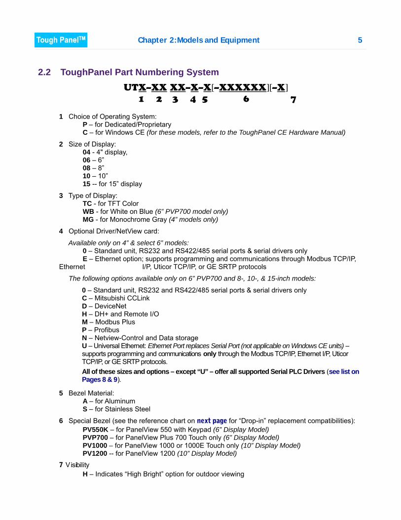
2.2 ToughPanel Part Numbering System
1 Choice of Operating System:P – for Dedicated/ProprietaryC – for Windows CE (for these models, refer to the ToughPanel CE Hardware Manual)
2 Size of Display:04 - 4" display, 06 – 6”08 – 8”10 – 10”15 -- for 15” display
3 Type of Display:TC - for TFT ColorWB - for White on Blue (6” PVP700 model only)MG - for Monochrome Gray (4” models only)
4 Optional Driver/NetView card:
Available only on 4” & select 6” models: 0 – Standard unit, RS232 and RS422/485 serial ports & serial drivers only E – Ethernet option; supports programming and communications through Modbus TCP/IP,
Ethernet I/P, Uticor TCP/IP, or GE SRTP protocols
The following options available only on 6” PVP700 and 8-, 10-, & 15-inch models:
0 – Standard unit, RS232 and RS422/485 serial ports & serial drivers onlyC – Mitsubishi CCLinkD – DeviceNet H – DH+ and Remote I/OM – Modbus PlusP – ProfibusN – Netview-Control and Data storage U – Universal Ethernet: Ethernet Port replaces Serial Port (not applicable on Windows CE units) –supports programming and communications only through the Modbus TCP/IP, Ethernet I/P, UticorTCP/IP, or GE SRTP protocols. All of these sizes and options – except “U” – offer all supported Serial PLC Drivers (see list onPages 8 & 9).
5 Bezel Material:A – for AluminumS – for Stainless Steel
6 Special Bezel (see the reference chart on next page for “Drop-in” replacement compatibilities): PV550K – for PanelView 550 with Keypad (6” Display Model) PVP700 – for PanelView Plus 700 Touch only (6” Display Model) PV1000 – for PanelView 1000 or 1000E Touch only (10” Display Model) PV1200 -- for PanelView 1200 (10” Display Model)
7 VisibilityH – Indicates “High Bright” option for outdoor viewing
UTX–XX XX–X–X[–XXXXXX][–X] 1 2 3 4 5 6 7
6 Chapter 2:Models and Equipment
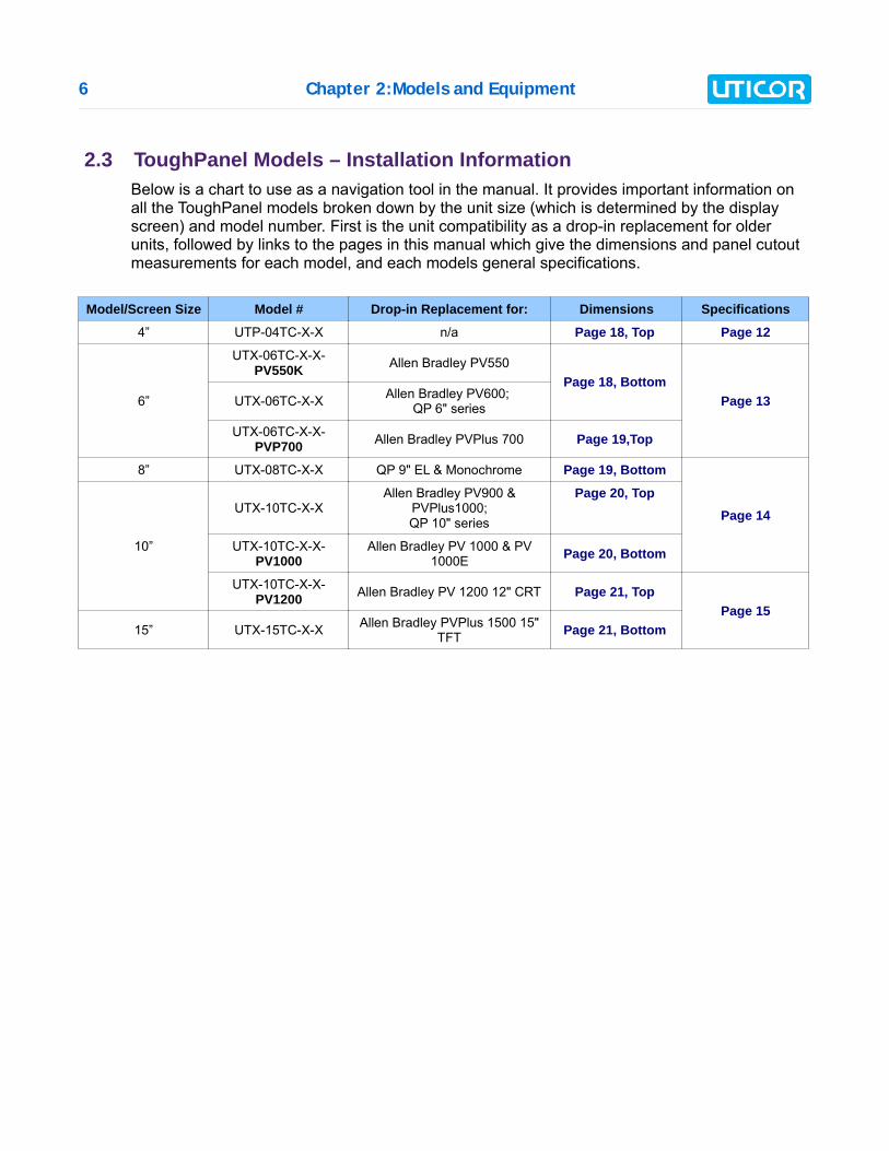
2.3 ToughPanel Models – Installation InformationBelow is a chart to use as a navigation tool in the manual. It provides important information onall the ToughPanel models broken down by the unit size (which is determined by the displayscreen) and model number. First is the unit compatibility as a drop-in replacement for olderunits, followed by links to the pages in this manual which give the dimensions and panel cutoutmeasurements for each model, and each models general specifications.
Model/Screen Size Model # Drop-in Replacement for: Dimensions Specifications
4” UTP-04TC-X-X n/a Page 18, Top Page 12
6”
UTX-06TC-X-X-PV550K Allen Bradley PV550
Page 18, BottomPage 13UTX-06TC-X-X Allen Bradley PV600;
QP 6" series
UTX-06TC-X-X-PVP700 Allen Bradley PVPlus 700 Page 19,Top
8” UTX-08TC-X-X QP 9" EL & Monochrome Page 19, Bottom
Page 14
10”
UTX-10TC-X-XAllen Bradley PV900 &
PVPlus1000;QP 10" series
Page 20, Top
UTX-10TC-X-X-PV1000
Allen Bradley PV 1000 & PV1000E Page 20, Bottom
UTX-10TC-X-X-PV1200 Allen Bradley PV 1200 12" CRT Page 21, Top
Page 1515” UTX-15TC-X-X Allen Bradley PVPlus 1500 15"
TFT Page 21, Bottom
Chapter 2:Models and Equipment 7
2.4 ToughPanel Features – All Models Pre-built panel components for easy screen design including a number of special parts, such
as: Toggle Switch, Slide Switch, Selector Switch, Throw Switch, Thumbwheel Object,Meters, PID Faceplates, and Analog/Digital Clock
Flash based design for easy firmware upgrade and field expandable user RAM Nonvolatile flash card option for user program backup Color models support 128-color palette for components and bitmaps Multiple languages (up to 9) Two communications ports — Computer (RS-232C) and PLC (RS-232C, RS-422A, or
RS-485A) Up to 999 screens Built-in clock and calendar or reference the PLC clock Built-in soft keypad for numeric and alphanumeric entry Password Protection for every touch object with passwords for up to 8 user groups 16 level undo and redo Import bitmaps Serial Printer support 40-character tag names to personally label PLC memory locations instead of cryptic PLC
addresses Statistical Process Control (SPC) Exclusive Netview and Control Dual Drivers - Most PLC and Network Protocols supported Data Acquisition Complete NEMA 4, 4X Industrial Ratings Network and I/O Card Options Light Weight / Low Power
8 Chapter 2:Models and Equipment
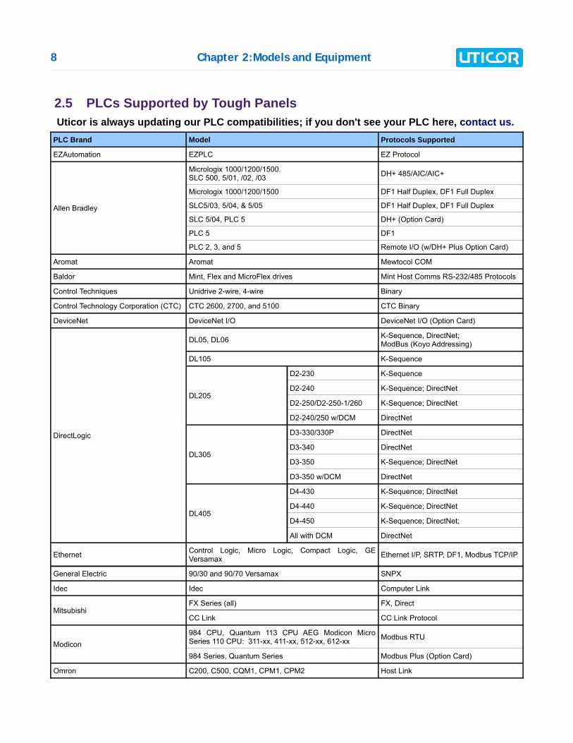
2.5 PLCs Supported by Tough PanelsUticor is always updating our PLC compatibilities; if you don't see your PLC here, contact us.
PLC Brand Model Protocols Supported
EZAutomation EZPLC EZ Protocol
Allen Bradley
Micrologix 1000/1200/1500. SLC 500, 5/01, /02, /03 DH+ 485/AIC/AIC+
Micrologix 1000/1200/1500 DF1 Half Duplex, DF1 Full Duplex
SLC5/03, 5/04, & 5/05 DF1 Half Duplex, DF1 Full Duplex
SLC 5/04, PLC 5 DH+ (Option Card)
PLC 5 DF1
PLC 2, 3, and 5 Remote I/O (w/DH+ Plus Option Card)
Aromat Aromat Mewtocol COM
Baldor Mint, Flex and MicroFlex drives Mint Host Comms RS-232/485 Protocols
Control Techniques Unidrive 2-wire, 4-wire Binary
Control Technology Corporation (CTC) CTC 2600, 2700, and 5100 CTC Binary
DeviceNet DeviceNet I/O DeviceNet I/O (Option Card)
DirectLogic
DL05, DL06 K-Sequence, DirectNet; ModBus (Koyo Addressing)
DL105 K-Sequence
DL205
D2-230 K-Sequence
D2-240 K-Sequence; DirectNet
D2-250/D2-250-1/260 K-Sequence; DirectNet
D2-240/250 w/DCM DirectNet
DL305
D3-330/330P DirectNet
D3-340 DirectNet
D3-350 K-Sequence; DirectNet
D3-350 w/DCM DirectNet
DL405
D4-430 K-Sequence; DirectNet
D4-440 K-Sequence; DirectNet
D4-450 K-Sequence; DirectNet;
All with DCM DirectNet
Ethernet Control Logic, Micro Logic, Compact Logic, GEVersamax Ethernet I/P, SRTP, DF1, Modbus TCP/IP
General Electric 90/30 and 90/70 Versamax SNPX
Idec Idec Computer Link
MitsubishiFX Series (all) FX, Direct
CC Link CC Link Protocol
Modicon984 CPU, Quantum 113 CPU AEG Modicon MicroSeries 110 CPU: 311-xx, 411-xx, 512-xx, 612-xx Modbus RTU
984 Series, Quantum Series Modbus Plus (Option Card)
Omron C200, C500, CQM1, CPM1, CPM2 Host Link
Chapter 2:Models and Equipment 9
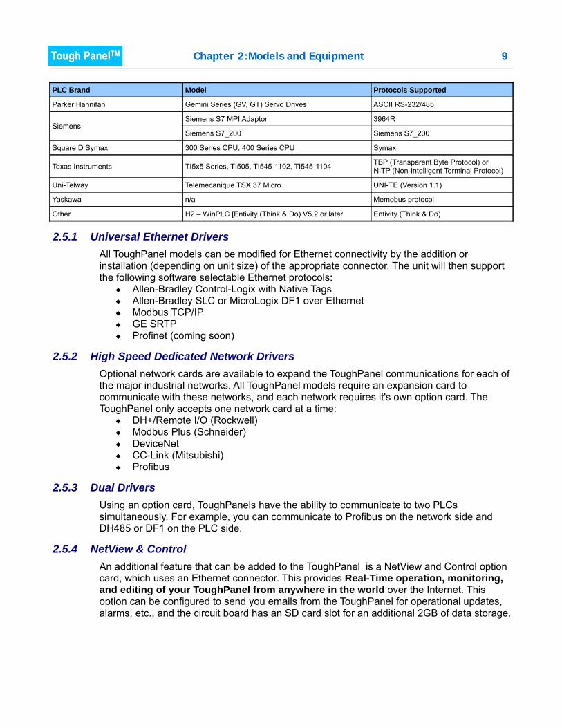
PLC Brand Model Protocols Supported
Parker Hannifan Gemini Series (GV, GT) Servo Drives ASCII RS-232/485
SiemensSiemens S7 MPI Adaptor 3964R
Siemens S7_200 Siemens S7_200
Square D Symax 300 Series CPU, 400 Series CPU Symax
Texas Instruments TI5x5 Series, TI505, TI545-1102, TI545-1104 TBP (Transparent Byte Protocol) or NITP (Non-Intelligent Terminal Protocol)
Uni-Telway Telemecanique TSX 37 Micro UNI-TE (Version 1.1)
Yaskawa n/a Memobus protocol
Other H2 – WinPLC [Entivity (Think & Do) V5.2 or later Entivity (Think & Do)
2.5.1 Universal Ethernet DriversAll ToughPanel models can be modified for Ethernet connectivity by the addition orinstallation (depending on unit size) of the appropriate connector. The unit will then supportthe following software selectable Ethernet protocols:
Allen-Bradley Control-Logix with Native Tags Allen-Bradley SLC or MicroLogix DF1 over Ethernet Modbus TCP/IP GE SRTP Profinet (coming soon)
2.5.2 High Speed Dedicated Network DriversOptional network cards are available to expand the ToughPanel communications for each ofthe major industrial networks. All ToughPanel models require an expansion card tocommunicate with these networks, and each network requires it's own option card. TheToughPanel only accepts one network card at a time:
DH+/Remote I/O (Rockwell) Modbus Plus (Schneider) DeviceNet CC-Link (Mitsubishi) Profibus
2.5.3 Dual DriversUsing an option card, ToughPanels have the ability to communicate to two PLCssimultaneously. For example, you can communicate to Profibus on the network side andDH485 or DF1 on the PLC side.
2.5.4 NetView & Control An additional feature that can be added to the ToughPanel is a NetView and Control optioncard, which uses an Ethernet connector. This provides Real-Time operation, monitoring,and editing of your ToughPanel from anywhere in the world over the Internet. Thisoption can be configured to send you emails from the ToughPanel for operational updates,alarms, etc., and the circuit board has an SD card slot for an additional 2GB of data storage.
10 Chapter 2:Models and Equipment
2.6 Optional Parts and AccessoriesThere are replacement parts and other optional equipment available to customize or upgradethe Tough Panel to fit your application. The tables below provide you with a list of thisequipment. Instructions, if necessary, on how to install this equipment to upgrade your unit arealso provided.
To order from these lists, phone UTICOR Technology, L. P. at 1-563-359-7501.
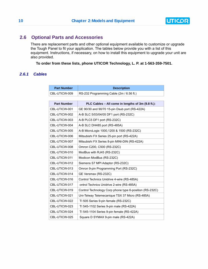
2.6.1 Cables
Part Number Description
CBL-UTICW-009 RS-232 Programming Cable (2m / 6.56 ft.)
Part Number PLC Cables – All come in lengths of 3m (9.8 ft.):
CBL-UTICW-001 GE 90/30 and 90/70 15-pin Dsub port (RS-422A)
CBL-UTICW-002 A-B SLC 5/03/04/05 DF1 port (RS-232C)
CBL-UTICW-003 A-B PLC5 DF1 port (RS-232C)
CBL-UTICW-004 A-B SLC DH485 port (RS-485A)
CBL-UTICW-005 A-B MicroLogix 1000,1200 & 1500 (RS-232C)
CBL-UTICW-006 Mitsubishi FX Series 25-pin port (RS-422A)
CBL-UTICW-007 Mitsubishi FX Series 8-pin MINI-DIN (RS-422A)
CBL-UTICW-008 Omron C200, C500 (RS-232C)
CBL-UTICW-010 ModBus with RJ45 (RS-232C)
CBL-UTICW-011 Modicon ModBus (RS-232C)
CBL-UTICW-012 Siemens S7 MPI Adaptor (RS-232C)
CBL-UTICW-013 Omron 9-pin Programming Port (RS-232C)
CBL-UTICW-014 GE Versmax (RS-232C)
CBL-UTICW-016 Control Technics Unidrive 4-wire (RS-485A)
CBL-UTICW-017 ontrol Technics Unidrive 2-wire (RS-485A)
CBL-UTICW-019 Control Technology Corp phone type 6-position (RS-232C)
CBL-UTICW-021 Uni-Telway Telemecanique TSX 37 Micro (RS-485A)
CBL-UTICW-022 TI 505 Series 9-pin female (RS-232C)
CBL-UTICW-023 TI 545-1102 Series 9-pin male (RS-422A)
CBL-UTICW-024 TI 545-1104 Series 9-pin female (RS-422A)
CBL-UTICW-025 Square D SYMAX 9-pin male (RS-422A)
Chapter 2:Models and Equipment 11
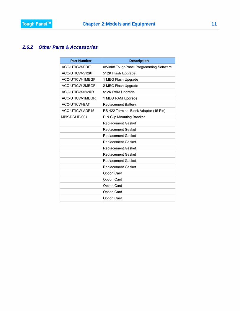
2.6.2 Other Parts & Accessories
Part Number Description
ACC-UTICW-EDIT uWin08 ToughPanel Programming Software
ACC-UTICW-512KF 512K Flash Upgrade
ACC-UTICW-1MEGF 1 MEG Flash Upgrade
ACC-UTICW-2MEGF 2 MEG Flash Upgrade
ACC-UTICW-512KR 512K RAM Upgrade
ACC-UTICW-1MEGR 1 MEG RAM Upgrade
ACC-UTICW-BAT Replacement Battery
ACC-UTICW-ADP15 RS-422 Terminal Block Adaptor (15 Pin)
MBK-DCLIP-001 DIN Clip Mounting Bracket
Replacement Gasket
Replacement Gasket
Replacement Gasket
Replacement Gasket
Replacement Gasket
Replacement Gasket
Replacement Gasket
Replacement Gasket
Option Card
Option Card
Option Card
Option Card
Option Card
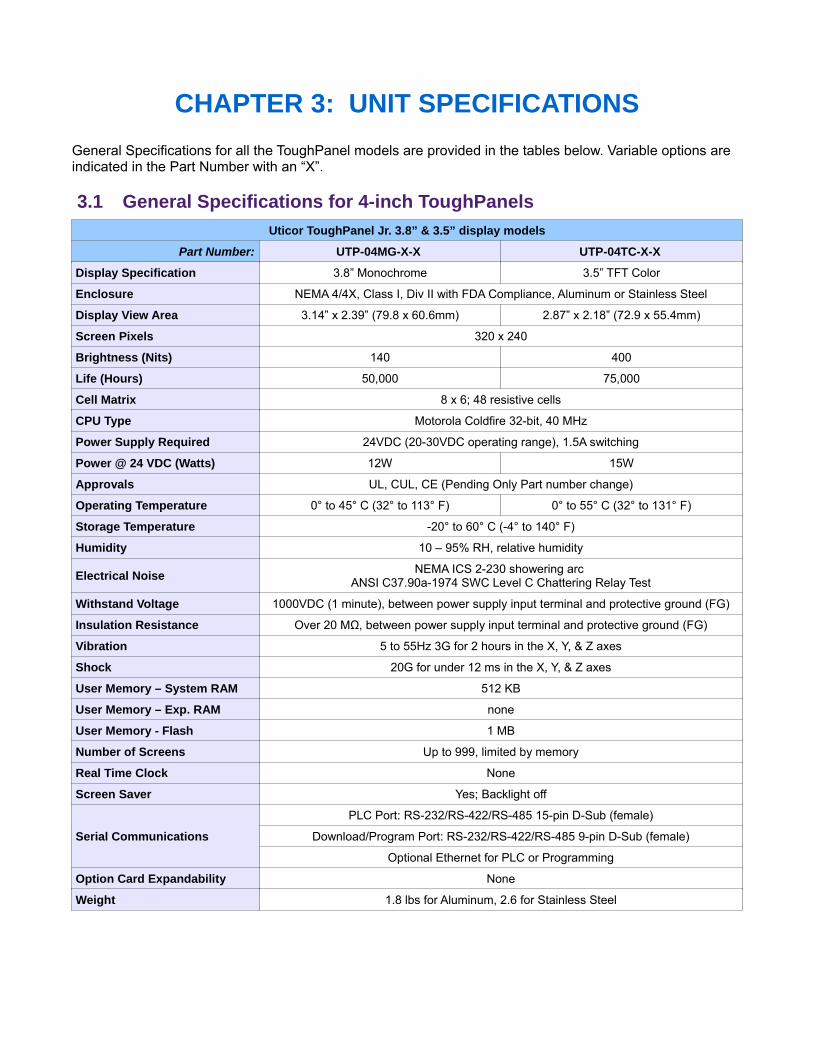
CHAPTER 3: UNIT SPECIFICATIONSGeneral Specifications for all the ToughPanel models are provided in the tables below. Variable options areindicated in the Part Number with an “X”.
3.1 General Specifications for 4-inch ToughPanelsUticor ToughPanel Jr. 3.8” & 3.5” display models
Part Number: UTP-04MG-X-X UTP-04TC-X-X
Display Specification 3.8” Monochrome 3.5” TFT Color
Enclosure NEMA 4/4X, Class I, Div II with FDA Compliance, Aluminum or Stainless Steel
Display View Area 3.14” x 2.39” (79.8 x 60.6mm) 2.87” x 2.18” (72.9 x 55.4mm)
Screen Pixels 320 x 240
Brightness (Nits) 140 400
Life (Hours) 50,000 75,000
Cell Matrix 8 x 6; 48 resistive cells
CPU Type Motorola Coldfire 32-bit, 40 MHz
Power Supply Required 24VDC (20-30VDC operating range), 1.5A switching
Power @ 24 VDC (Watts) 12W 15W
Approvals UL, CUL, CE (Pending Only Part number change)
Operating Temperature 0° to 45° C (32° to 113° F) 0° to 55° C (32° to 131° F)
Storage Temperature -20° to 60° C (-4° to 140° F)
Humidity 10 – 95% RH, relative humidity
Electrical Noise NEMA ICS 2-230 showering arc ANSI C37.90a-1974 SWC Level C Chattering Relay Test
Withstand Voltage 1000VDC (1 minute), between power supply input terminal and protective ground (FG)
Insulation Resistance Over 20 MΩ, between power supply input terminal and protective ground (FG)
Vibration 5 to 55Hz 3G for 2 hours in the X, Y, & Z axes
Shock 20G for under 12 ms in the X, Y, & Z axes
User Memory – System RAM 512 KB
User Memory – Exp. RAM none
User Memory - Flash 1 MB
Number of Screens Up to 999, limited by memory
Real Time Clock None
Screen Saver Yes; Backlight off
Serial Communications
PLC Port: RS-232/RS-422/RS-485 15-pin D-Sub (female)
Download/Program Port: RS-232/RS-422/RS-485 9-pin D-Sub (female)
Optional Ethernet for PLC or Programming
Option Card Expandability None
Weight 1.8 lbs for Aluminum, 2.6 for Stainless Steel
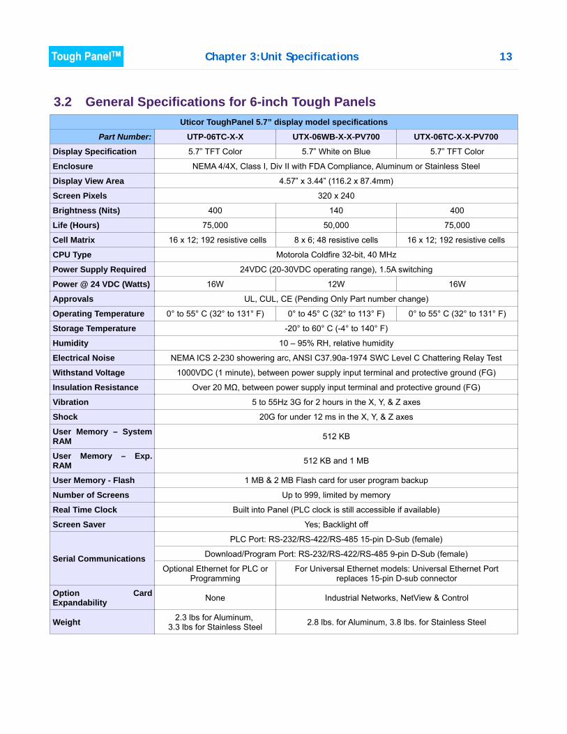
Chapter 3:Unit Specifications 13
3.2 General Specifications for 6-inch Tough PanelsUticor ToughPanel 5.7” display model specifications
Part Number: UTP-06TC-X-X UTX-06WB-X-X-PV700 UTX-06TC-X-X-PV700
Display Specification 5.7” TFT Color 5.7” White on Blue 5.7” TFT Color
Enclosure NEMA 4/4X, Class I, Div II with FDA Compliance, Aluminum or Stainless Steel
Display View Area 4.57” x 3.44” (116.2 x 87.4mm)
Screen Pixels 320 x 240
Brightness (Nits) 400 140 400
Life (Hours) 75,000 50,000 75,000
Cell Matrix 16 x 12; 192 resistive cells 8 x 6; 48 resistive cells 16 x 12; 192 resistive cells
CPU Type Motorola Coldfire 32-bit, 40 MHz
Power Supply Required 24VDC (20-30VDC operating range), 1.5A switching
Power @ 24 VDC (Watts) 16W 12W 16W
Approvals UL, CUL, CE (Pending Only Part number change)
Operating Temperature 0° to 55° C (32° to 131° F) 0° to 45° C (32° to 113° F) 0° to 55° C (32° to 131° F)
Storage Temperature -20° to 60° C (-4° to 140° F)
Humidity 10 – 95% RH, relative humidity
Electrical Noise NEMA ICS 2-230 showering arc, ANSI C37.90a-1974 SWC Level C Chattering Relay Test
Withstand Voltage 1000VDC (1 minute), between power supply input terminal and protective ground (FG)
Insulation Resistance Over 20 MΩ, between power supply input terminal and protective ground (FG)
Vibration 5 to 55Hz 3G for 2 hours in the X, Y, & Z axes
Shock 20G for under 12 ms in the X, Y, & Z axes
User Memory – SystemRAM 512 KB
User Memory – Exp.RAM 512 KB and 1 MB
User Memory - Flash 1 MB & 2 MB Flash card for user program backup
Number of Screens Up to 999, limited by memory
Real Time Clock Built into Panel (PLC clock is still accessible if available)
Screen Saver Yes; Backlight off
Serial Communications
PLC Port: RS-232/RS-422/RS-485 15-pin D-Sub (female)
Download/Program Port: RS-232/RS-422/RS-485 9-pin D-Sub (female)
Optional Ethernet for PLC orProgramming
For Universal Ethernet models: Universal Ethernet Portreplaces 15-pin D-sub connector
Option CardExpandability None Industrial Networks, NetView & Control
Weight 2.3 lbs for Aluminum, 3.3 lbs for Stainless Steel 2.8 lbs. for Aluminum, 3.8 lbs. for Stainless Steel
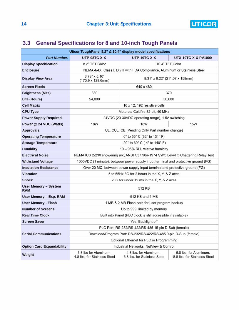
14 Chapter 3:Unit Specifications
3.3 General Specifications for 8 and 10-inch Tough PanelsUticor ToughPanel 8.2” & 10.4” display model specifications
Part Number: UTP-08TC-X-X UTP-10TC-X-X UTX-10TC-X-X-PV1000
Display Specification 8.2” TFT Color 10.4” TFT Color
Enclosure NEMA 4/4X, Class I, Div II with FDA Compliance, Aluminum or Stainless Steel
Display View Area 6.73” x 5.10”(170.9 x 129.6mm) 8.31” x 6.22” (211.07 x 158mm)
Screen Pixels 640 x 480
Brightness (Nits) 330 370
Life (Hours) 54,000 50,000
Cell Matrix 16 x 12; 192 resistive cells
CPU Type Motorola Coldfire 32-bit, 40 MHz
Power Supply Required 24VDC (20-30VDC operating range), 1.5A switching
Power @ 24 VDC (Watts) 18W 18W 15W
Approvals UL, CUL, CE (Pending Only Part number change)
Operating Temperature 0° to 55° C (32° to 131° F)
Storage Temperature -20° to 60° C (-4° to 140° F)
Humidity 10 – 95% RH, relative humidity
Electrical Noise NEMA ICS 2-230 showering arc, ANSI C37.90a-1974 SWC Level C Chattering Relay Test
Withstand Voltage 1000VDC (1 minute), between power supply input terminal and protective ground (FG)
Insulation Resistance Over 20 MΩ, between power supply input terminal and protective ground (FG)
Vibration 5 to 55Hz 3G for 2 hours in the X, Y, & Z axes
Shock 20G for under 12 ms in the X, Y, & Z axes
User Memory – SystemRAM 512 KB
User Memory – Exp. RAM 512 KB and 1 MB
User Memory - Flash 1 MB & 2 MB Flash card for user program backup
Number of Screens Up to 999, limited by memory
Real Time Clock Built into Panel (PLC clock is still accessible if available)
Screen Saver Yes; Backlight off
Serial Communications
PLC Port: RS-232/RS-422/RS-485 15-pin D-Sub (female)
Download/Program Port: RS-232/RS-422/RS-485 9-pin D-Sub (female)
Optional Ethernet for PLC or Programming
Option Card Expandability Industrial Networks, NetView & Control
Weight 3.8 lbs for Aluminum, 4.8 lbs. for Stainless Steel
4.8 lbs. for Aluminum, 6.8 lbs. for Stainless Steel
6.8 lbs. for Aluminum, 8.8 lbs. for Stainless Steel
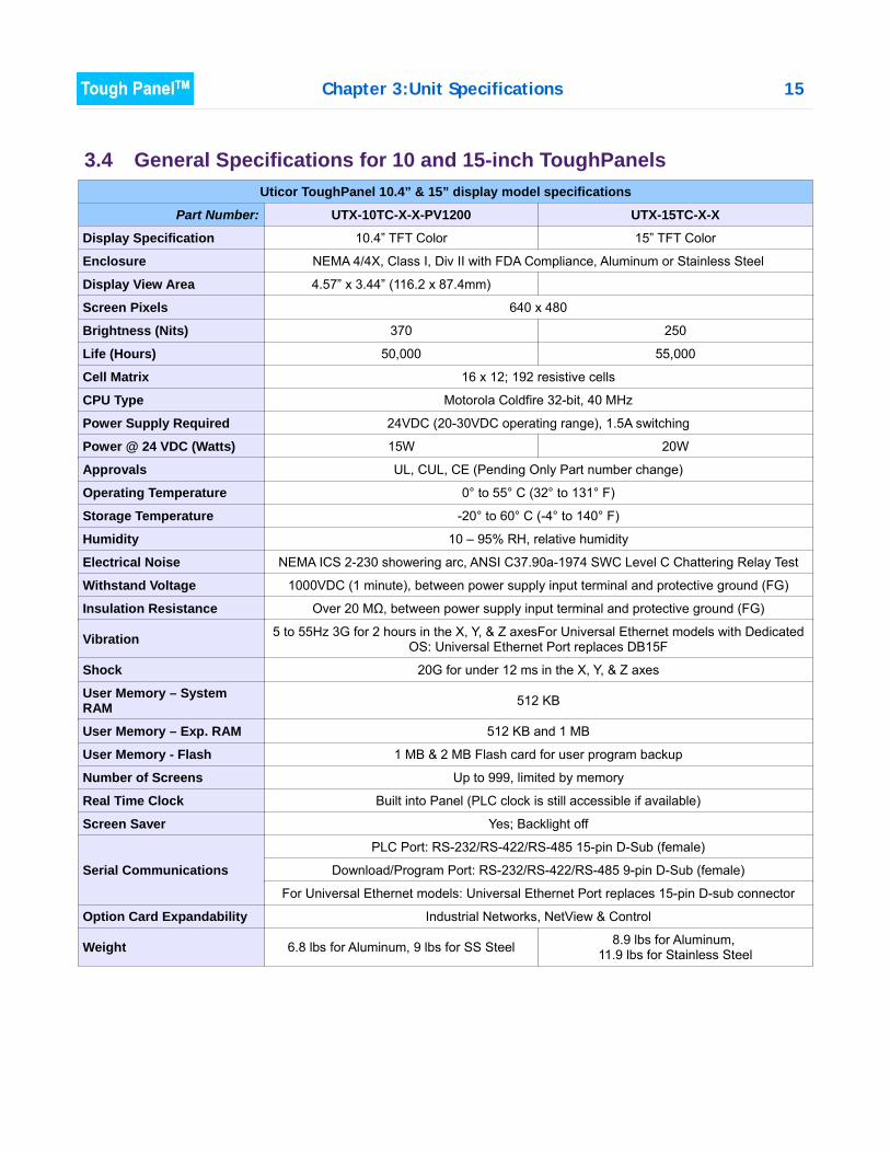
Chapter 3:Unit Specifications 15
3.4 General Specifications for 10 and 15-inch ToughPanelsUticor ToughPanel 10.4” & 15” display model specifications
Part Number: UTX-10TC-X-X-PV1200 UTX-15TC-X-X
Display Specification 10.4” TFT Color 15” TFT Color
Enclosure NEMA 4/4X, Class I, Div II with FDA Compliance, Aluminum or Stainless Steel
Display View Area 4.57” x 3.44” (116.2 x 87.4mm)
Screen Pixels 640 x 480
Brightness (Nits) 370 250
Life (Hours) 50,000 55,000
Cell Matrix 16 x 12; 192 resistive cells
CPU Type Motorola Coldfire 32-bit, 40 MHz
Power Supply Required 24VDC (20-30VDC operating range), 1.5A switching
Power @ 24 VDC (Watts) 15W 20W
Approvals UL, CUL, CE (Pending Only Part number change)
Operating Temperature 0° to 55° C (32° to 131° F)
Storage Temperature -20° to 60° C (-4° to 140° F)
Humidity 10 – 95% RH, relative humidity
Electrical Noise NEMA ICS 2-230 showering arc, ANSI C37.90a-1974 SWC Level C Chattering Relay Test
Withstand Voltage 1000VDC (1 minute), between power supply input terminal and protective ground (FG)
Insulation Resistance Over 20 MΩ, between power supply input terminal and protective ground (FG)
Vibration 5 to 55Hz 3G for 2 hours in the X, Y, & Z axesFor Universal Ethernet models with DedicatedOS: Universal Ethernet Port replaces DB15F
Shock 20G for under 12 ms in the X, Y, & Z axes
User Memory – SystemRAM 512 KB
User Memory – Exp. RAM 512 KB and 1 MB
User Memory - Flash 1 MB & 2 MB Flash card for user program backup
Number of Screens Up to 999, limited by memory
Real Time Clock Built into Panel (PLC clock is still accessible if available)
Screen Saver Yes; Backlight off
Serial Communications
PLC Port: RS-232/RS-422/RS-485 15-pin D-Sub (female)
Download/Program Port: RS-232/RS-422/RS-485 9-pin D-Sub (female)
For Universal Ethernet models: Universal Ethernet Port replaces 15-pin D-sub connector
Option Card Expandability Industrial Networks, NetView & Control
Weight 6.8 lbs for Aluminum, 9 lbs for SS Steel 8.9 lbs for Aluminum, 11.9 lbs for Stainless Steel
CHAPTER 4: INSTALLATION
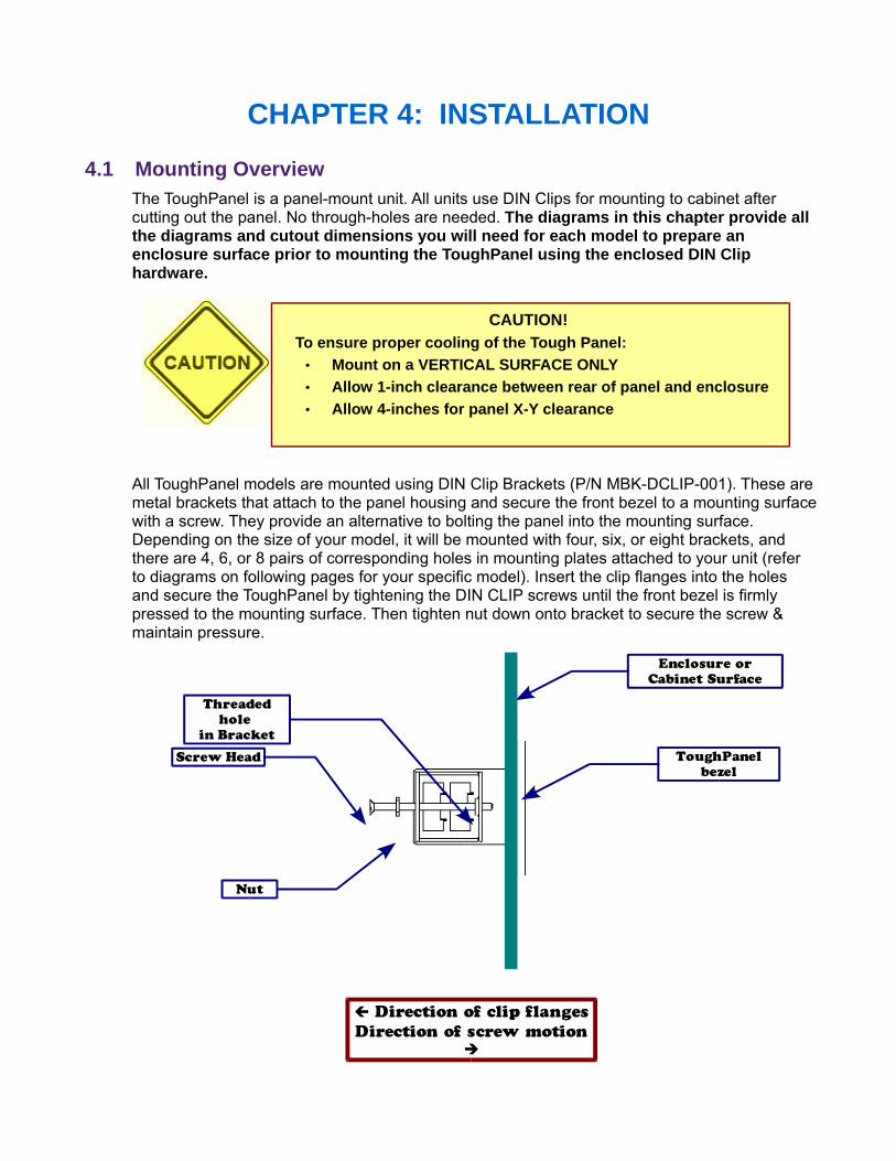
4.1 Mounting OverviewThe ToughPanel is a panel-mount unit. All units use DIN Clips for mounting to cabinet aftercutting out the panel. No through-holes are needed. The diagrams in this chapter provide allthe diagrams and cutout dimensions you will need for each model to prepare anenclosure surface prior to mounting the ToughPanel using the enclosed DIN Cliphardware.
All ToughPanel models are mounted using DIN Clip Brackets (P/N MBK-DCLIP-001). These aremetal brackets that attach to the panel housing and secure the front bezel to a mounting surfacewith a screw. They provide an alternative to bolting the panel into the mounting surface.Depending on the size of your model, it will be mounted with four, six, or eight brackets, andthere are 4, 6, or 8 pairs of corresponding holes in mounting plates attached to your unit (referto diagrams on following pages for your specific model). Insert the clip flanges into the holesand secure the ToughPanel by tightening the DIN CLIP screws until the front bezel is firmlypressed to the mounting surface. Then tighten nut down onto bracket to secure the screw &maintain pressure.
CAUTION! To ensure proper cooling of the Tough Panel: • Mount on a VERTICAL SURFACE ONLY • Allow 1-inch clearance between rear of panel and enclosure• Allow 4-inches for panel X-Y clearance
Threaded
hole
in Bracket
Screw Head
Enclosure or
Cabinet Surface
ToughPanel
bezel
Nut
Direction of clip flanges
Direction of screw motion
Chapter 4:Installation 17
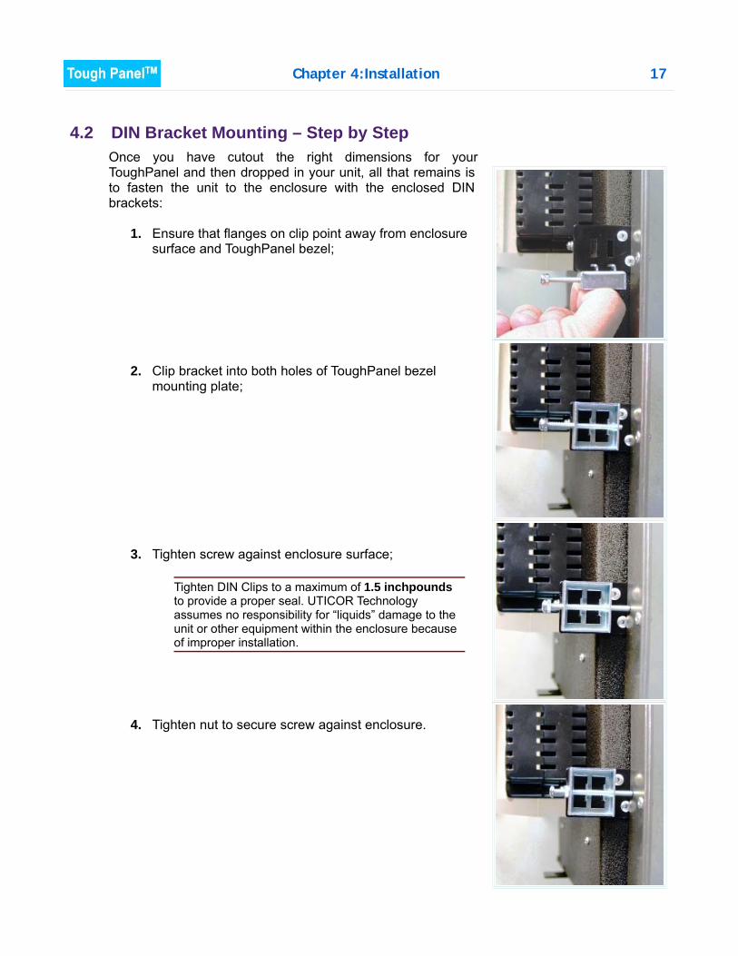
4.2 DIN Bracket Mounting – Step by StepOnce you have cutout the right dimensions for yourToughPanel and then dropped in your unit, all that remains isto fasten the unit to the enclosure with the enclosed DINbrackets:
1. Ensure that flanges on clip point away from enclosuresurface and ToughPanel bezel;
2. Clip bracket into both holes of ToughPanel bezelmounting plate;
3. Tighten screw against enclosure surface;
Tighten DIN Clips to a maximum of 1.5 inchpoundsto provide a proper seal. UTICOR Technologyassumes no responsibility for “liquids” damage to theunit or other equipment within the enclosure becauseof improper installation.
4. Tighten nut to secure screw against enclosure.
18 Chapter 4:Installation
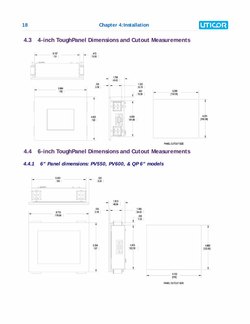
4.3 4-inch ToughPanel Dimensions and Cutout Measurements
4.4 6-inch ToughPanel Dimensions and Cutout Measurements
4.4.1 6” Panel dimensions: PV550, PV600, & QP 6” models
Chapter 4:Installation 19
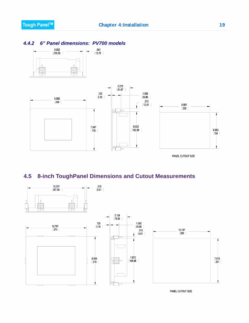
4.4.2 6” Panel dimensions: PV700 models
4.5 8-inch ToughPanel Dimensions and Cutout Measurements
20 Chapter 4:Installation
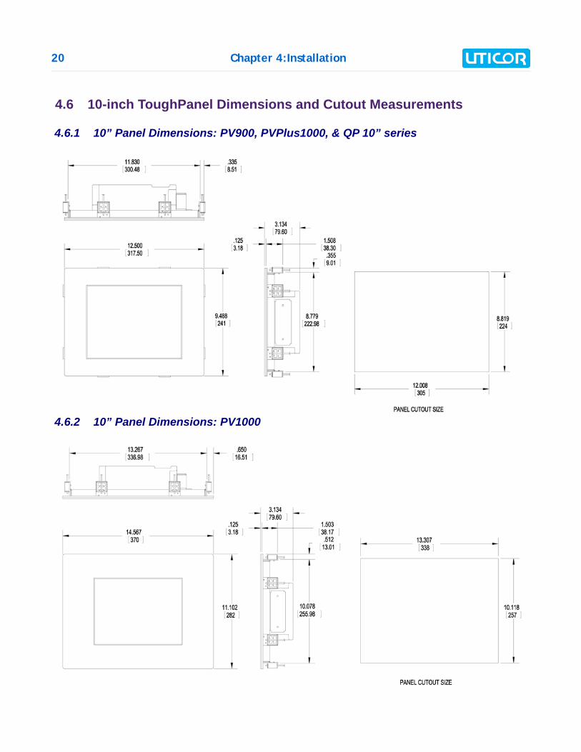
4.6 10-inch ToughPanel Dimensions and Cutout Measurements
4.6.1 10” Panel Dimensions: PV900, PVPlus1000, & QP 10” series
4.6.2 10” Panel Dimensions: PV1000
Chapter 4:Installation 21
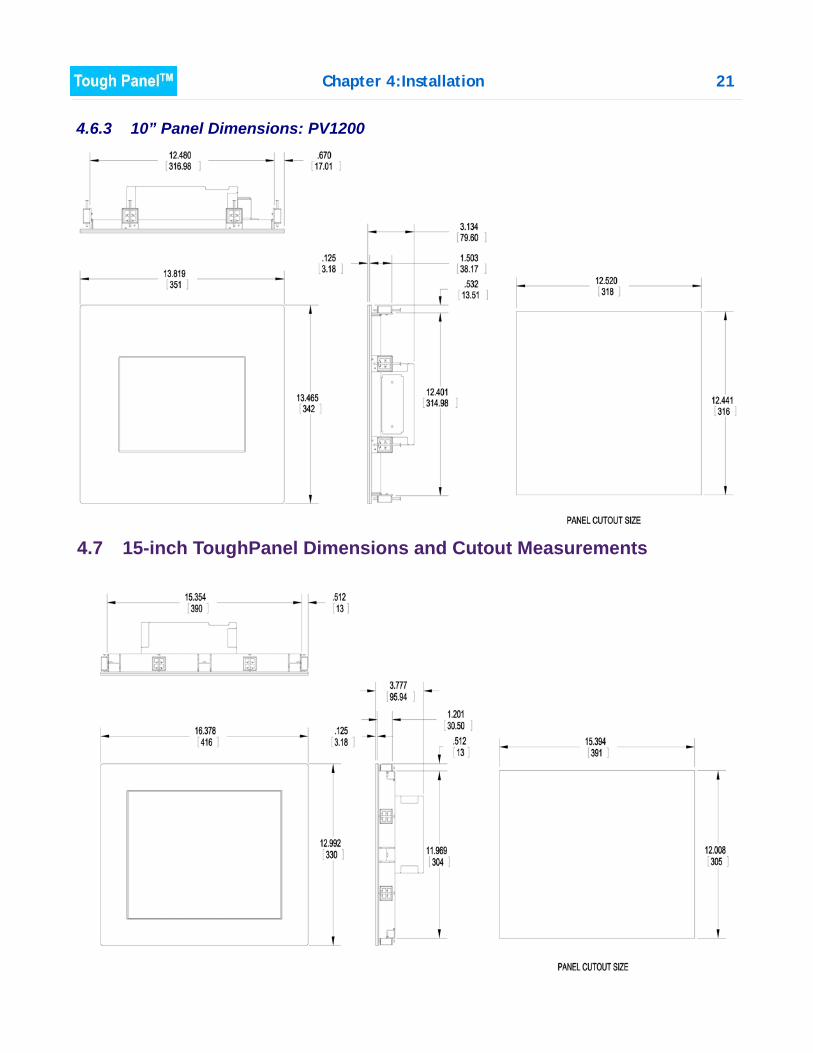
4.6.3 10” Panel Dimensions: PV1200
4.7 15-inch ToughPanel Dimensions and Cutout Measurements
22 Chapter 4:Installation
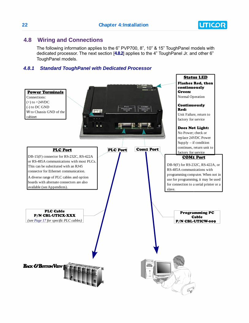
4.8 Wiring and ConnectionsThe following information applies to the 6” PVP700, 8”, 10” & 15” ToughPanel models withdedicated processor. The next section [4.8.2] applies to the 4” ToughPanel Jr. and other 6”ToughPanel models.
4.8.1 Standard ToughPanel with Dedicated Processor
BACK & BOTTOM VIEW
Power Terminals
Connections:(+) to +24VDC(-) to DC GNDW to Chassis GND of the cabinet
PLC Port
DB-15(F) connector for RS-232C, RS-422A or RS-485A communications with most PLCs. This can be substituted with an RJ45 connector for Ethernet communication.
A diverse range of PLC cables and option boards with alternate connectors are also available (see Appendices).
Status LED
Flashes Red, then
continuously
Green:
Normal Operation
Continuously
Red:
Unit Failure, return to factory for service
Does Not Light:
No Power; check or replace 24VDC Power Supply – if condition continues, return unit to factory for service
COM1 Port
DB-9(F) for RS-232C, RS-422A, or RS-485A communications with programming computer. When not in use for programming, it may be used for connection to a serial printer or a slave.
PLC Cable
P/N CBL-UTICX-XXX
(see Page 17 for specific PLC cables)
Programming PC
Cable
P/N CBL-UTICW-009
PLC Port Com1 Port

Chapter 4:Installation 23
24 Chapter 4:Installation
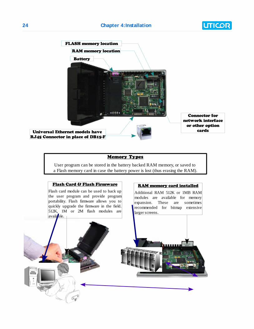
Connector for
network interface
or other option
cards
FLASH memory location
RAM memory location
Battery
Universal Ethernet models have
RJ45 Connector in place of DB15-F
Flash Card & Flash Firmware
Flash card module can be used to back up the user program and provide program portability. Flash firmware allows you to quickly upgrade the firmware in the field. 512K, 1M or 2M flash modules are available.
RAM memory card installed
Additional RAM 512K or 1MB RAM modules are available for memory expansion. These are sometimes recommended for bitmap extensive larger screens.
Memory Types
User program can be stored in the battery backed RAM memory, or saved to a Flash memory card in case the battery power is lost (thus erasing the RAM).
Chapter 4:Installation 25
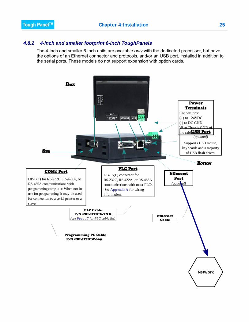
4.8.2 4-inch and smaller footprint 6-inch ToughPanelsThe 4-inch and smaller 6-inch units are available only with the dedicated processor, but havethe options of an Ethernet connector and protocols, and/or an USB port, installed in addition tothe serial ports. These models do not support expansion with option cards.
BACK
SIDE
BOTTOM
Ethernet
Cable
Ethernet
Port
(optional)
Network
COM1 Port
DB-9(F) for RS-232C, RS-422A, or RS-485A communications with programming computer. When not in use for programming, it may be used for connection to a serial printer or a slave.
PLC Port
DB-15(F) connector for RS-232C, RS-422A, or RS-485A communications with most PLCs. See Appendix A for wiring information.
PLC Cable
P/N CBL-UTICX-XXX
(see Page 17 for PLC cable list)
Programming PC Cable
P/N CBL-UTICW-009
USB Port
(optional)
Supports USB mouse, keyboards and a majority
of USB flash drives.
Power
Terminals
Connections:(+) to +24VDC(-) to DC GNDW to Chassis GND of the cabinet
26 Chapter 4:Installation
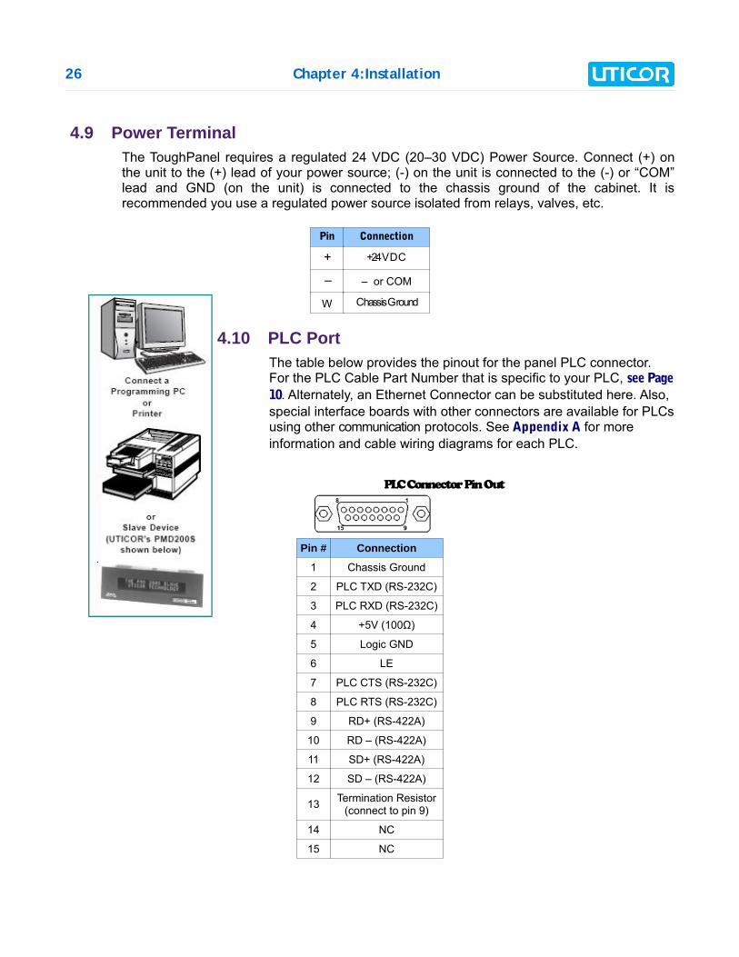
4.9 Power TerminalThe ToughPanel requires a regulated 24 VDC (20–30 VDC) Power Source. Connect (+) onthe unit to the (+) lead of your power source; (-) on the unit is connected to the (-) or “COM”lead and GND (on the unit) is connected to the chassis ground of the cabinet. It isrecommended you use a regulated power source isolated from relays, valves, etc.
Pin Connection
+ +24VDC
– – or COM
W Chassis Ground
4.10 PLC PortThe table below provides the pinout for the panel PLC connector.For the PLC Cable Part Number that is specific to your PLC, see Page10. Alternately, an Ethernet Connector can be substituted here. Also,special interface boards with other connectors are available for PLCsusing other communication protocols. See Appendix A for moreinformation and cable wiring diagrams for each PLC.
PLC Connector Pin Out
Pin # Connection
1 Chassis Ground
2 PLC TXD (RS-232C)
3 PLC RXD (RS-232C)
4 +5V (100Ω)
5 Logic GND
6 LE
7 PLC CTS (RS-232C)
8 PLC RTS (RS-232C)
9 RD+ (RS-422A)
10 RD – (RS-422A)
11 SD+ (RS-422A)
12 SD – (RS-422A)
13 Termination Resistor(connect to pin 9)
14 NC
15 NC
Chapter 4:Installation 27
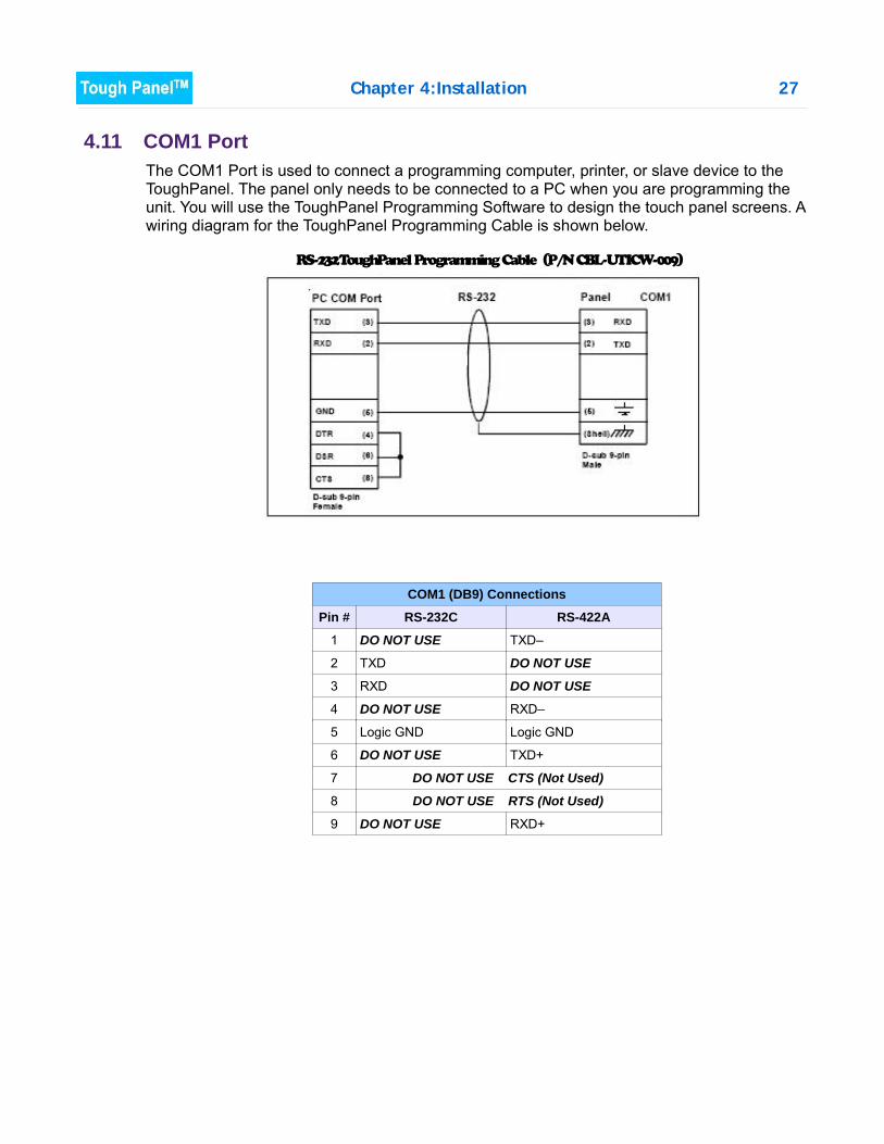
4.11 COM1 PortThe COM1 Port is used to connect a programming computer, printer, or slave device to theToughPanel. The panel only needs to be connected to a PC when you are programming theunit. You will use the ToughPanel Programming Software to design the touch panel screens. Awiring diagram for the ToughPanel Programming Cable is shown below.
COM1 (DB9) Connections
Pin # RS-232C RS-422A
1 DO NOT USE TXD–
2 TXD DO NOT USE
3 RXD DO NOT USE
4 DO NOT USE RXD–
5 Logic GND Logic GND
6 DO NOT USE TXD+
7 DO NOT USE CTS (Not Used)
8 DO NOT USE RTS (Not Used)
9 DO NOT USE RXD+
RS-232 ToughPanel Programming Cable (P/N CBL-UTICW-009)
28 Chapter 4:Installation
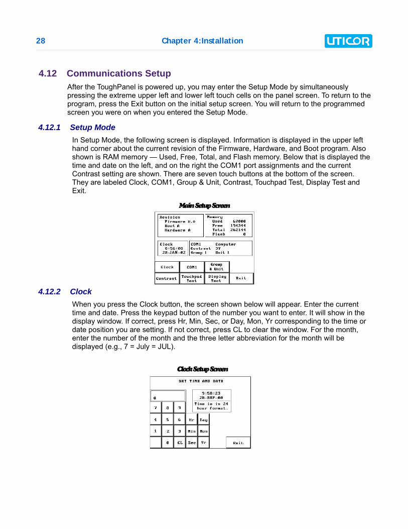
4.12 Communications SetupAfter the ToughPanel is powered up, you may enter the Setup Mode by simultaneouslypressing the extreme upper left and lower left touch cells on the panel screen. To return to theprogram, press the Exit button on the initial setup screen. You will return to the programmedscreen you were on when you entered the Setup Mode.
4.12.1 Setup ModeIn Setup Mode, the following screen is displayed. Information is displayed in the upper lefthand corner about the current revision of the Firmware, Hardware, and Boot program. Alsoshown is RAM memory — Used, Free, Total, and Flash memory. Below that is displayed thetime and date on the left, and on the right the COM1 port assignments and the currentContrast setting are shown. There are seven touch buttons at the bottom of the screen.They are labeled Clock, COM1, Group & Unit, Contrast, Touchpad Test, Display Test andExit.
4.12.2 ClockWhen you press the Clock button, the screen shown below will appear. Enter the currenttime and date. Press the keypad button of the number you want to enter. It will show in thedisplay window. If correct, press Hr, Min, Sec, or Day, Mon, Yr corresponding to the time ordate position you are setting. If not correct, press CL to clear the window. For the month,enter the number of the month and the three letter abbreviation for the month will bedisplayed (e.g., 7 = July = JUL).
Main Setup Screen
Clock Setup Screen
Chapter 4:Installation 29
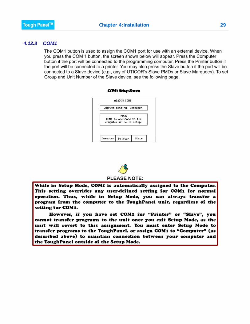
4.12.3 COM1The COM1 button is used to assign the COM1 port for use with an external device. Whenyou press the COM 1 button, the screen shown below will appear. Press the Computerbutton if the port will be connected to the programming computer. Press the Printer button ifthe port will be connected to a printer. You may also press the Slave button if the port will beconnected to a Slave device (e.g., any of UTICOR’s Slave PMDs or Slave Marquees). To setGroup and Unit Number of the Slave device, see the following page.
PLEASE NOTE:
COM1 Setup Screen
While in Setup Mode, COM1 is automatically assigned to the Computer.
This setting overrides any user-defined setting for COM1 for normal
operation. Thus, while in Setup Mode, you can always transfer a
program from the computer to the ToughPanel unit, regardless of the
setting for COM1.
However, if you have set COM1 for “Printer” or “Slave”, you
cannot transfer programs to the unit once you exit Setup Mode, as the
unit will revert to this assignment. You must enter Setup Mode to
transfer programs to the ToughPanel, or assign COM1 to “Computer” (as
described above) to maintain connection between your computer and
the ToughPanel outside of the Setup Mode.
30 Chapter 4:Installation
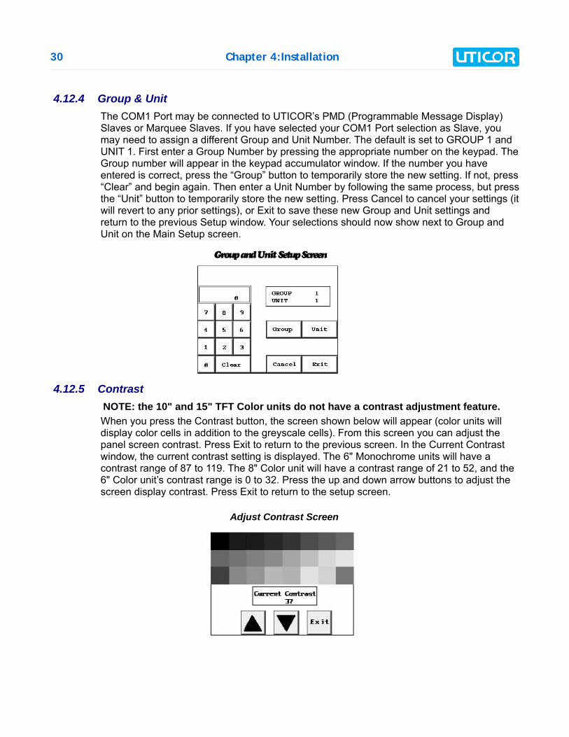
4.12.4 Group & UnitThe COM1 Port may be connected to UTICOR’s PMD (Programmable Message Display)Slaves or Marquee Slaves. If you have selected your COM1 Port selection as Slave, youmay need to assign a different Group and Unit Number. The default is set to GROUP 1 andUNIT 1. First enter a Group Number by pressing the appropriate number on the keypad. TheGroup number will appear in the keypad accumulator window. If the number you haveentered is correct, press the “Group” button to temporarily store the new setting. If not, press“Clear” and begin again. Then enter a Unit Number by following the same process, but pressthe “Unit” button to temporarily store the new setting. Press Cancel to cancel your settings (itwill revert to any prior settings), or Exit to save these new Group and Unit settings andreturn to the previous Setup window. Your selections should now show next to Group andUnit on the Main Setup screen.
4.12.5 ContrastNOTE: the 10" and 15" TFT Color units do not have a contrast adjustment feature.When you press the Contrast button, the screen shown below will appear (color units willdisplay color cells in addition to the greyscale cells). From this screen you can adjust thepanel screen contrast. Press Exit to return to the previous screen. In the Current Contrastwindow, the current contrast setting is displayed. The 6" Monochrome units will have acontrast range of 87 to 119. The 8" Color unit will have a contrast range of 21 to 52, and the6" Color unit’s contrast range is 0 to 32. Press the up and down arrow buttons to adjust thescreen display contrast. Press Exit to return to the setup screen.
Group and Unit Setup Screen
Adjust Contrast Screen
Chapter 4:Installation 31
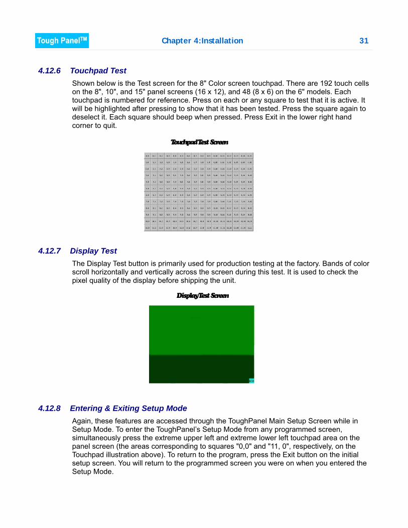
4.12.6 Touchpad TestShown below is the Test screen for the 8" Color screen touchpad. There are 192 touch cellson the 8", 10", and 15" panel screens (16 x 12), and 48 (8 x 6) on the 6" models. Eachtouchpad is numbered for reference. Press on each or any square to test that it is active. Itwill be highlighted after pressing to show that it has been tested. Press the square again todeselect it. Each square should beep when pressed. Press Exit in the lower right handcorner to quit.
4.12.7 Display TestThe Display Test button is primarily used for production testing at the factory. Bands of colorscroll horizontally and vertically across the screen during this test. It is used to check thepixel quality of the display before shipping the unit.
4.12.8 Entering & Exiting Setup ModeAgain, these features are accessed through the ToughPanel Main Setup Screen while inSetup Mode. To enter the ToughPanel’s Setup Mode from any programmed screen,simultaneously press the extreme upper left and extreme lower left touchpad area on thepanel screen (the areas corresponding to squares "0,0" and "11, 0", respectively, on theTouchpad illustration above). To return to the program, press the Exit button on the initialsetup screen. You will return to the programmed screen you were on when you entered theSetup Mode.
Touchpad Test Screen
Display Test Screen

CHAPTER 5: MAINTENANCE
5.1 Shutting Off Power to ToughPanelRemoving power from the ToughPanel does not normally cause a loss of the user program thatis stored in the panel unless the battery voltage is low or the battery has been removed. A lowbattery may be indicated by a system alarm provided in our software that, when programmed,will display a message on all user-programmed screens.* It is recommended that you back upyour user program on multiple PC disks and/or install a flash option card, which will provide anonvolatile storage of the user program.
The steps to install a Flash option card and to load the user program onto a Flash option cardare as follows:
1. Run the uWin08 Software and connect the PC serial port to COM1 on the panel. Powerup the panel.If the user program is not stored on the connected PC, then “Transfer theprogram from the panel.” See the following instructions (next page), “To save program tocomputer disk, ...”
2. Then save the user program to disk by performing the following steps: a) Power down panel. b) Install Flash option card c) Power up panel. d) Transfer saved program to the panel. (At end of program upload, you will be asked if
you want to transfer the program to Flash.)
3. From the Start Screen (Project Information, Step 1), under SELECT ACTION, click on EditProgram ON-LINE. Click Panel > Flash > RAM to Flash.
4. The user program will now be stored to both the Flash and RAM memory.
5. Each time the panel is powered with the Flash card installed, the user program will loadfrom the nonvolatile Flash option card to the battery-backed user RAM. This is a veryuseful feature for performing field upgrades or changes to user programs. OEMs cansend updated Flash cards to field locations for operators to upgrade their systemswithout using a PC!
* A low battery sets a System Attribute that may be
programmed to display an alarm. You must program the
attribute and alarm for this to happen. This function can
be found in the uWin08 software under Setup > Project
Attributes > Panel to PLC > Low Battery. See the
Software Help or Software Manual for instructions.
Chapter 5:Maintenance 33
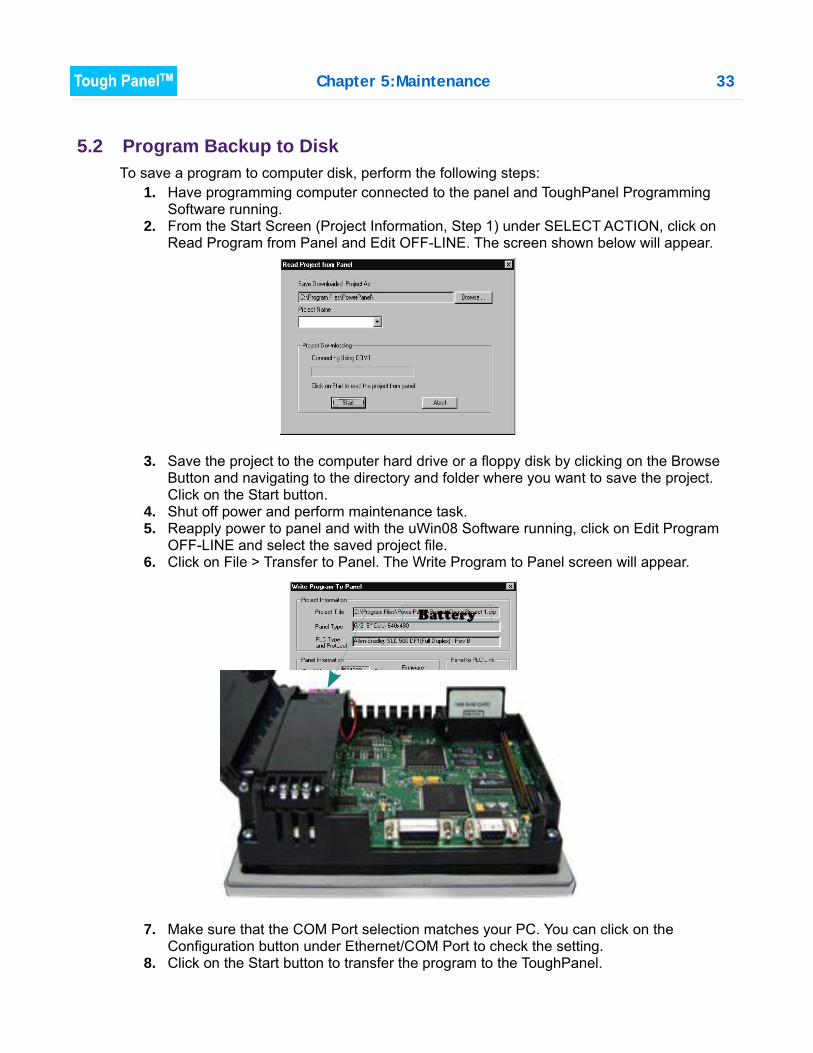
5.2 Program Backup to DiskTo save a program to computer disk, perform the following steps:
1. Have programming computer connected to the panel and ToughPanel ProgrammingSoftware running.
2. From the Start Screen (Project Information, Step 1) under SELECT ACTION, click onRead Program from Panel and Edit OFF-LINE. The screen shown below will appear.
3. Save the project to the computer hard drive or a floppy disk by clicking on the BrowseButton and navigating to the directory and folder where you want to save the project.Click on the Start button.
4. Shut off power and perform maintenance task.5. Reapply power to panel and with the uWin08 Software running, click on Edit Program
OFF-LINE and select the saved project file.6. Click on File > Transfer to Panel. The Write Program to Panel screen will appear.
7. Make sure that the COM Port selection matches your PC. You can click on theConfiguration button under Ethernet/COM Port to check the setting.
8. Click on the Start button to transfer the program to the ToughPanel.
Battery

34 Chapter 5:Maintenance

Chapter 5:Maintenance 35
5.3 Lithium Battery Replacement
Typical battery life is 5 years.
1. Connect ToughPanel to a computer and save the user program to disk (instructions onpreceding page).
2. Disconnect power source.3. Open back cover (shown open in figure below) to access the battery.4. The battery is located in the upper-left hand corner as shown in the figure below.
Remove old battery and replace with a new 1/2 AA, 3.6 V Lithium Battery (Part NumberACC-UTICW-BAT).
5. Close rear cover and ensure that the door latches.6. Reconnect power source, connect to PC, run ToughPanel uWin08 Software, and follow
instructions to transfer the user program that was previously saved to disk.
BEFORE REMOVING BATTERY, back up the user programand save in accordance with the instructions on the preceding page.
36 Chapter 5:Maintenance
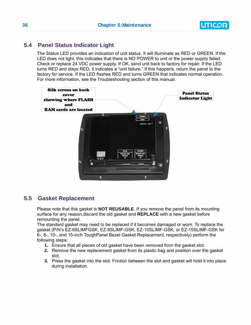
5.4 Panel Status Indicator LightThe Status LED provides an indication of unit status. It will illuminate as RED or GREEN. If theLED does not light, this indicates that there is NO POWER to unit or the power supply failed.Check or replace 24 VDC power supply. If OK, send unit back to factory for repair. If the LEDturns RED and stays RED, it indicates a “unit failure.” If this happens, return the panel to thefactory for service. If the LED flashes RED and turns GREEN that indicates normal operation.For more information, see the Troubleshooting section of this manual.
5.5 Gasket Replacement
Please note that this gasket is NOT REUSABLE. If you remove the panel from its mountingsurface for any reason,discard the old gasket and REPLACE with a new gasket beforeremounting the panel.The standard gasket may need to be replaced if it becomes damaged or worn. To replace thegasket (P/N’s EZ-6SLIMFGSK, EZ-8SLIMF-GSK, EZ-10SLIMF-GSK, or EZ-15SLIMF-GSK for6-, 8-, 10-, and 15-inch ToughPanel Bezel Gasket Replacement, respectively) perform thefollowing steps:
1. Ensure that all pieces of old gasket have been removed from the gasket slot.2. Remove the new replacement gasket from its plastic bag and position over the gasket
slot.3. Press the gasket into the slot. Friction between the slot and gasket will hold it into place
during installation.
Silk screen on back
cover
showing where FLASH
and
RAM cards are located
Panel Status
Indicator Light
Chapter 5:Maintenance 37
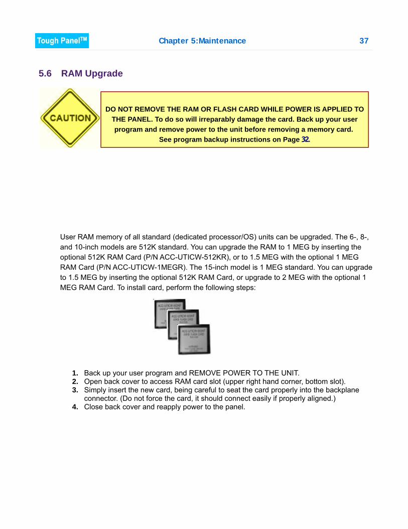
5.6 RAM Upgrade
User RAM memory of all standard (dedicated processor/OS) units can be upgraded. The 6-, 8-,and 10-inch models are 512K standard. You can upgrade the RAM to 1 MEG by inserting theoptional 512K RAM Card (P/N ACC-UTICW-512KR), or to 1.5 MEG with the optional 1 MEGRAM Card (P/N ACC-UTICW-1MEGR). The 15-inch model is 1 MEG standard. You can upgradeto 1.5 MEG by inserting the optional 512K RAM Card, or upgrade to 2 MEG with the optional 1MEG RAM Card. To install card, perform the following steps:
1. Back up your user program and REMOVE POWER TO THE UNIT.2. Open back cover to access RAM card slot (upper right hand corner, bottom slot).3. Simply insert the new card, being careful to seat the card properly into the backplane
connector. (Do not force the card, it should connect easily if properly aligned.) 4. Close back cover and reapply power to the panel.
DO NOT REMOVE THE RAM OR FLASH CARD WHILE POWER IS APPLIED TOTHE PANEL. To do so will irreparably damage the card. Back up your userprogram and remove power to the unit before removing a memory card.
See program backup instructions on Page 32.
38 Chapter 5:Maintenance
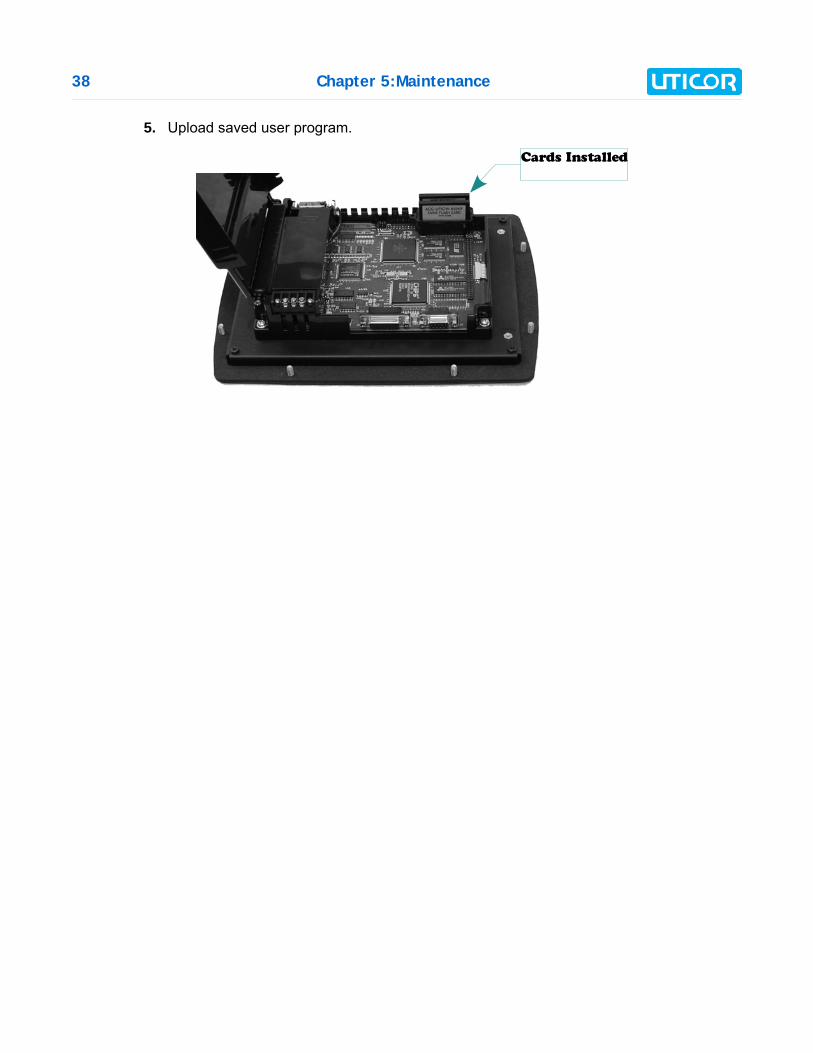
5. Upload saved user program.
Cards Installed
Chapter 5:Maintenance 39
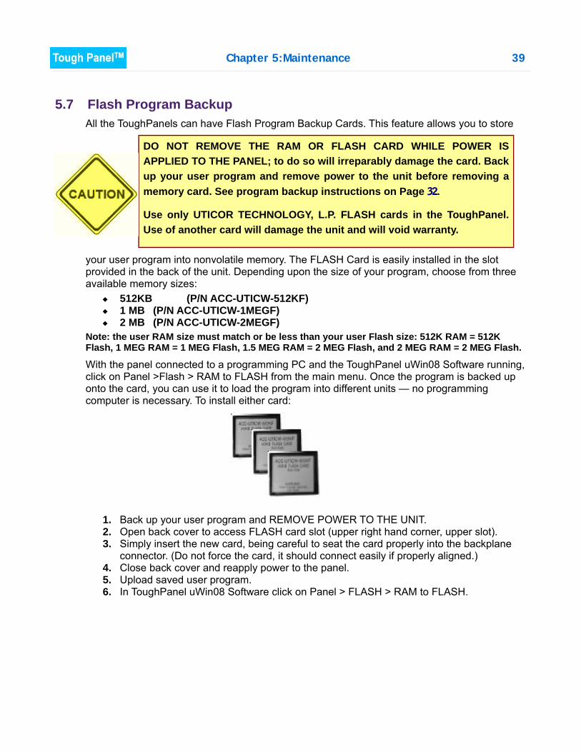
5.7 Flash Program BackupAll the ToughPanels can have Flash Program Backup Cards. This feature allows you to store
your user program into nonvolatile memory. The FLASH Card is easily installed in the slotprovided in the back of the unit. Depending upon the size of your program, choose from threeavailable memory sizes:
512KB (P/N ACC-UTICW-512KF) 1 MB (P/N ACC-UTICW-1MEGF) 2 MB (P/N ACC-UTICW-2MEGF)
Note: the user RAM size must match or be less than your user Flash size: 512K RAM = 512KFlash, 1 MEG RAM = 1 MEG Flash, 1.5 MEG RAM = 2 MEG Flash, and 2 MEG RAM = 2 MEG Flash.
With the panel connected to a programming PC and the ToughPanel uWin08 Software running,click on Panel >Flash > RAM to FLASH from the main menu. Once the program is backed uponto the card, you can use it to load the program into different units — no programmingcomputer is necessary. To install either card:
1. Back up your user program and REMOVE POWER TO THE UNIT.2. Open back cover to access FLASH card slot (upper right hand corner, upper slot).3. Simply insert the new card, being careful to seat the card properly into the backplane
connector. (Do not force the card, it should connect easily if properly aligned.)4. Close back cover and reapply power to the panel.5. Upload saved user program.6. In ToughPanel uWin08 Software click on Panel > FLASH > RAM to FLASH.
DO NOT REMOVE THE RAM OR FLASH CARD WHILE POWER ISAPPLIED TO THE PANEL; to do so will irreparably damage the card. Backup your user program and remove power to the unit before removing amemory card. See program backup instructions on Page 32.
Use only UTICOR TECHNOLOGY, L.P. FLASH cards in the ToughPanel.Use of another card will damage the unit and will void warranty.

40 Chapter 5:Maintenance
5.8 Fuse ResetThe internal fuse does not require replacement. It is reset by removing power for 5 minutes andthen reapplying power to the unit.
5.9 Fluorescent Backlight Bulb ReplacementGenerally, the backlight bulb life far exceeds the manufacturer’s expected life. Themanufacturer’s expected half-life rates are provided in the specifications tables in Chapter 3.
5.10 Precautions:
To ensure the longevity and effectiveness of the ToughPanel please take note of the followingprecautions:
Do not press sharp objects against the screen. Do not strike the panel with hard objects. Do not press the screen with excessive force. Once the panel is mounted and has power applied, do not place any objects over the
ventilation slots. This will result in heat buildup and may damage the unit.
NOTE: Using the Screen Saver feature in the uWin08
software should significantly extend the life of the
fluorescent backlight bulb!
To program the Screen Saver feature, go to the uWin08 main
menu item Objects > System Objects > Screen Saver.
Chapter 5:Maintenance 41
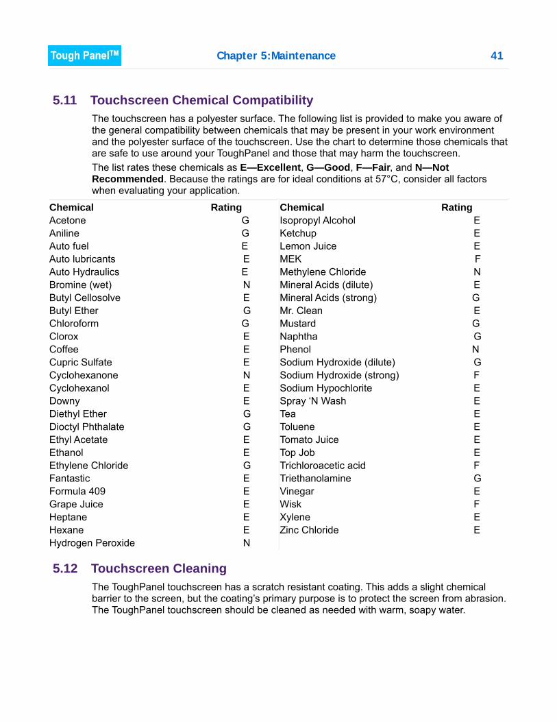
5.11 Touchscreen Chemical CompatibilityThe touchscreen has a polyester surface. The following list is provided to make you aware ofthe general compatibility between chemicals that may be present in your work environmentand the polyester surface of the touchscreen. Use the chart to determine those chemicals thatare safe to use around your ToughPanel and those that may harm the touchscreen. The list rates these chemicals as E—Excellent, G—Good, F—Fair, and N—NotRecommended. Because the ratings are for ideal conditions at 57°C, consider all factorswhen evaluating your application.
Chemical RatingAcetone GAniline GAuto fuel EAuto lubricants EAuto Hydraulics EBromine (wet) NButyl Cellosolve EButyl Ether GChloroform GClorox ECoffee ECupric Sulfate ECyclohexanone NCyclohexanol EDowny EDiethyl Ether GDioctyl Phthalate GEthyl Acetate EEthanol EEthylene Chloride GFantastic EFormula 409 EGrape Juice EHeptane EHexane EHydrogen Peroxide N
Chemical RatingIsopropyl Alcohol EKetchup ELemon Juice EMEK FMethylene Chloride NMineral Acids (dilute) EMineral Acids (strong) GMr. Clean EMustard GNaphtha GPhenol NSodium Hydroxide (dilute) GSodium Hydroxide (strong) FSodium Hypochlorite ESpray ‘N Wash ETea EToluene ETomato Juice ETop Job ETrichloroacetic acid FTriethanolamine GVinegar EWisk FXylene EZinc Chloride E
5.12 Touchscreen CleaningThe ToughPanel touchscreen has a scratch resistant coating. This adds a slight chemicalbarrier to the screen, but the coating’s primary purpose is to protect the screen from abrasion.The ToughPanel touchscreen should be cleaned as needed with warm, soapy water.
CHAPTER 6: TROUBLESHOOTING
6.1 Common Problems:
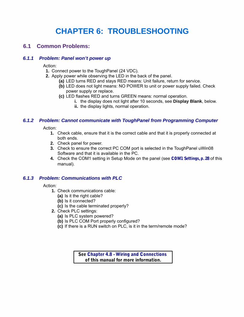
6.1.1 Problem: Panel won’t power upAction: 1. Connect power to the ToughPanel (24 VDC). 2. Apply power while observing the LED in the back of the panel.
(a) LED turns RED and stays RED means: Unit failure, return for service.(b) LED does not light means: NO POWER to unit or power supply failed. Check
power supply or replace.(c) LED flashes RED and turns GREEN means: normal operation.
i. the display does not light after 10 seconds, see Display Blank, below. ii. the display lights, normal operation.
6.1.2 Problem: Cannot communicate with ToughPanel from Programming ComputerAction:
1. Check cable, ensure that it is the correct cable and that it is properly connected atboth ends.
2. Check panel for power.3. Check to ensure the correct PC COM port is selected in the ToughPanel uWin08
Software and that it is available in the PC.4. Check the COM1 setting in Setup Mode on the panel (see COM1 Settings, p. 28 of this
manual).
6.1.3 Problem: Communications with PLCAction:
1. Check communications cable:(a) Is it the right cable?(b) Is it connected?(c) Is the cable terminated properly?
2. Check PLC settings:(a) Is PLC system powered?(b) Is PLC COM Port properly configured?(c) If there is a RUN switch on PLC, is it in the term/remote mode?
See Chapter 4.8 - Wiring and Connections of this manual for more information.
Chapter 6:Troubleshooting 43
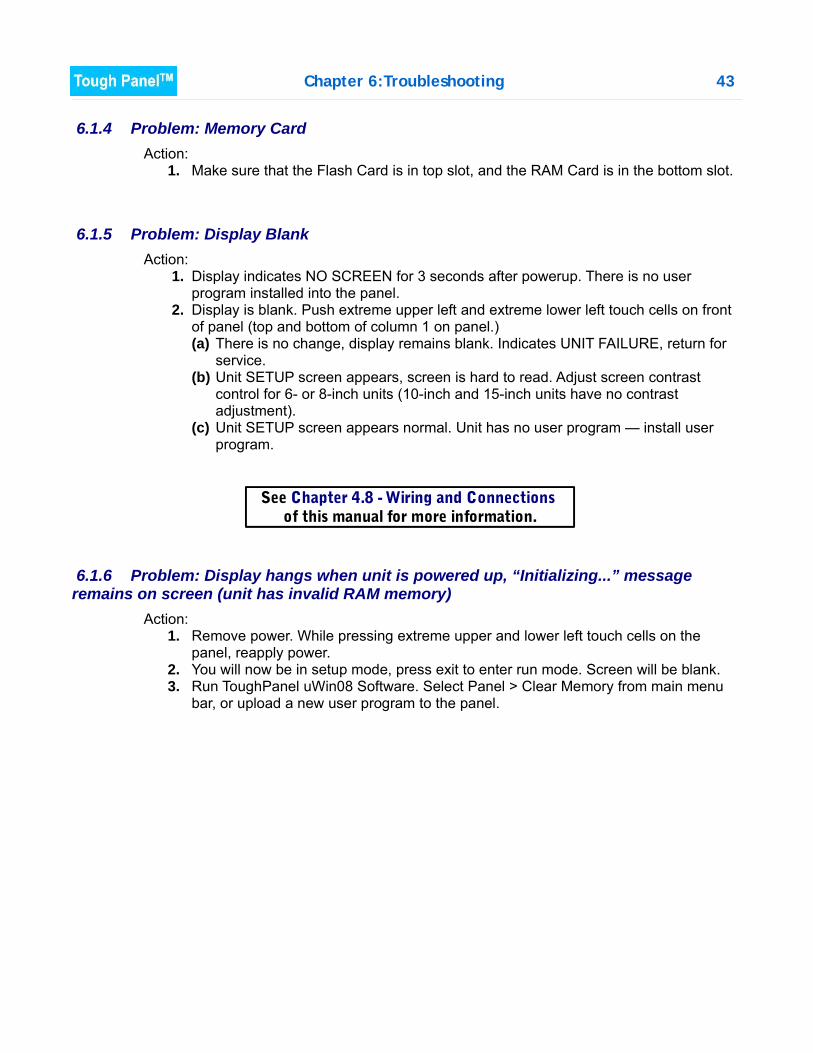
6.1.4 Problem: Memory CardAction:
1. Make sure that the Flash Card is in top slot, and the RAM Card is in the bottom slot.
6.1.5 Problem: Display BlankAction:
1. Display indicates NO SCREEN for 3 seconds after powerup. There is no userprogram installed into the panel.
2. Display is blank. Push extreme upper left and extreme lower left touch cells on frontof panel (top and bottom of column 1 on panel.)(a) There is no change, display remains blank. Indicates UNIT FAILURE, return for
service.(b) Unit SETUP screen appears, screen is hard to read. Adjust screen contrast
control for 6- or 8-inch units (10-inch and 15-inch units have no contrastadjustment).
(c) Unit SETUP screen appears normal. Unit has no user program — install userprogram.
6.1.6 Problem: Display hangs when unit is powered up, “Initializing...” messageremains on screen (unit has invalid RAM memory)
Action:1. Remove power. While pressing extreme upper and lower left touch cells on the
panel, reapply power.2. You will now be in setup mode, press exit to enter run mode. Screen will be blank.3. Run ToughPanel uWin08 Software. Select Panel > Clear Memory from main menu
bar, or upload a new user program to the panel.
See Chapter 4.8 - Wiring and Connections of this manual for more information.
44 Chapter 6:Troubleshooting
6.2 Still Need Help?
Other than this manual, you have two additional sources for more information : Visit our website at www.uticor.net. Our web site contains information about any new
feature releases, technical support, plus much more ... Call our Technical Support Group at 1-800-832-3647 or FAX us at 1-563-359-9094.
If you have any questions that you can’t find an answer to, give us a call at the number aboveand we will be glad to assist you.
6.2.1 Warranty RepairsIf your ToughPanel is under warranty, contact UTICOR Technology, L.P. @ 1-563-359-7501.
6.2.2 Out of Warranty RepairsIf your ToughPanel is out of warranty, contact UTICOR Technology’s Service Department foran evaluation of repair costs @ 1-563-359-7501. You can then decide whether it is moreeconomical to proceed with factory repairs or purchase a new panel.

45
Appendix A: PLC Cable Wiring Diagrams
The following diagrams depict the wiring pinouts for the ToughPanel to PLC cables. Uticor can providethese cables, and the Uticor Part Number is given for each type of cable. The PLC Serial Port on theToughPanel is a D-sub,15 Female connector. The pinout chart & wiring diagram for the PLC Port canbe found on Page 25.
The ToughPanel supports most PLCs and serial drivers; if you do not see your PLC type listed here,refer to the PLC Cables list on Page 10, or contact UTICOR Technology, L. P. at 1-563-359-7501 forwiring information.
46
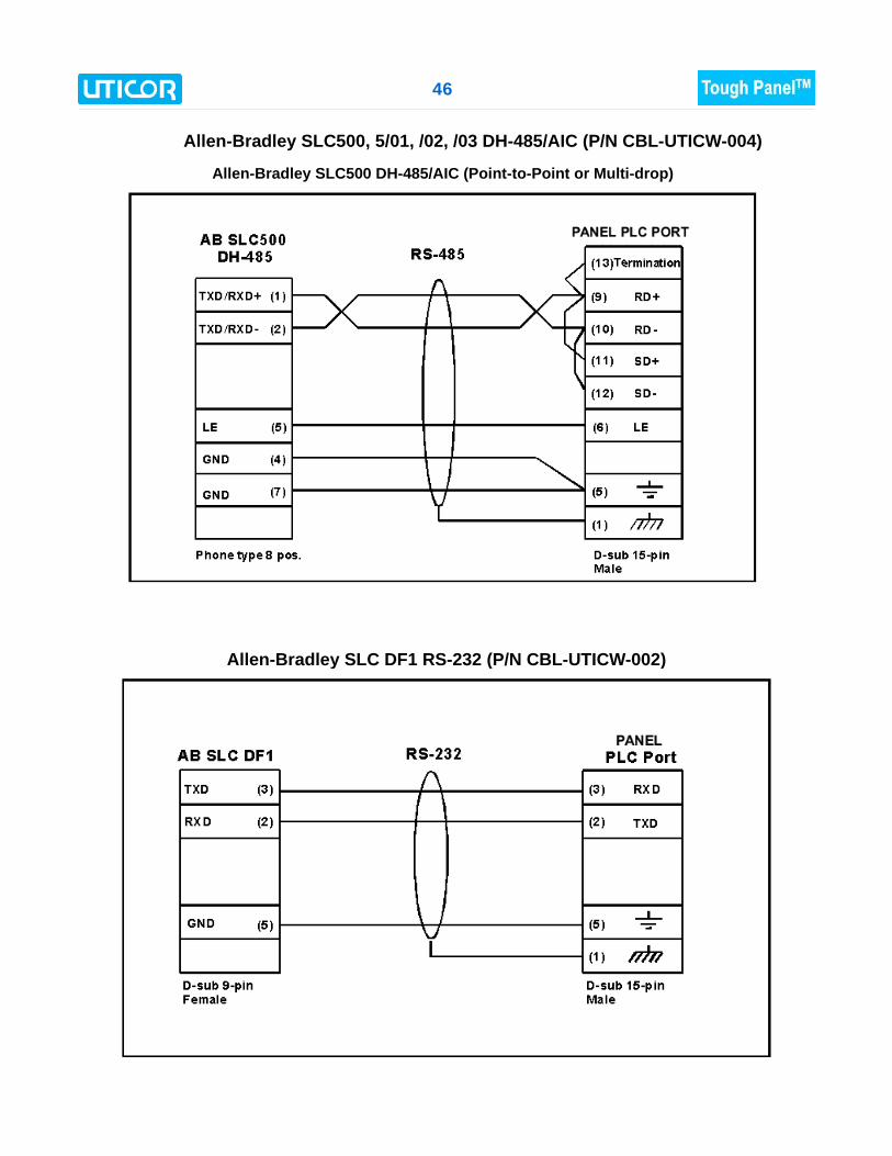
Allen-Bradley SLC500, 5/01, /02, /03 DH-485/AIC (P/N CBL-UTICW-004)
Allen-Bradley SLC DF1 RS-232 (P/N CBL-UTICW-002)
Allen-Bradley SLC500 DH-485/AIC (Point-to-Point or Multi-drop)
47
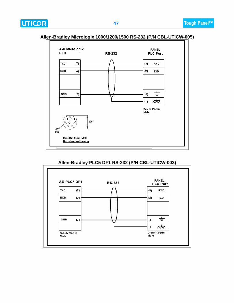
Allen-Bradley Micrologix 1000/1200/1500 RS-232 (P/N CBL-UTICW-005)
Allen-Bradley PLC5 DF1 RS-232 (P/N CBL-UTICW-003)
48
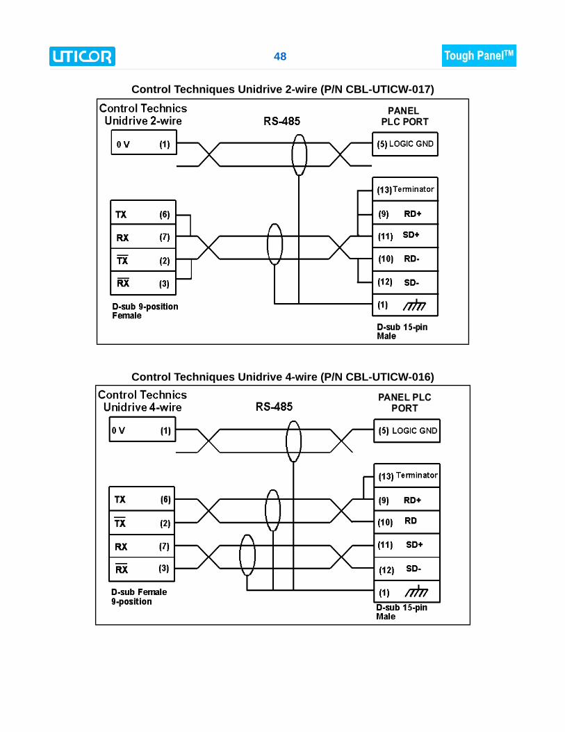
Control Techniques Unidrive 2-wire (P/N CBL-UTICW-017)
Control Techniques Unidrive 4-wire (P/N CBL-UTICW-016)
49
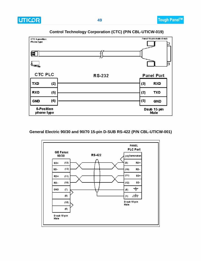
Control Technology Corporation (CTC) (P/N CBL-UTICW-019)
General Electric 90/30 and 90/70 15-pin D-SUB RS-422 (P/N CBL-UTICW-001)
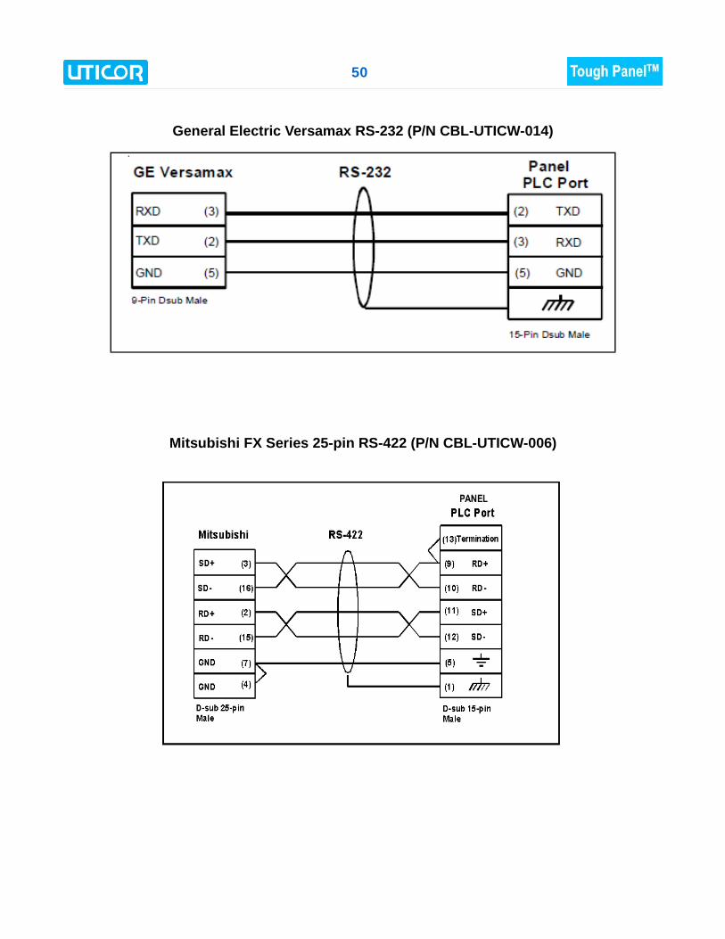
50
General Electric Versamax RS-232 (P/N CBL-UTICW-014)
Mitsubishi FX Series 25-pin RS-422 (P/N CBL-UTICW-006)
51
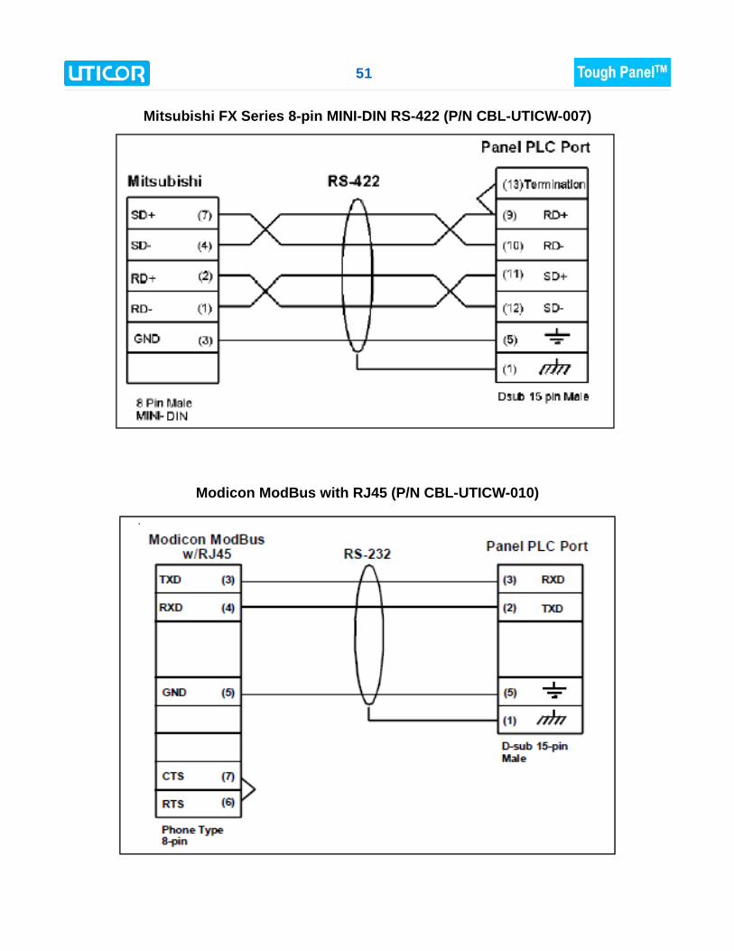
Mitsubishi FX Series 8-pin MINI-DIN RS-422 (P/N CBL-UTICW-007)
Modicon ModBus with RJ45 (P/N CBL-UTICW-010)
52
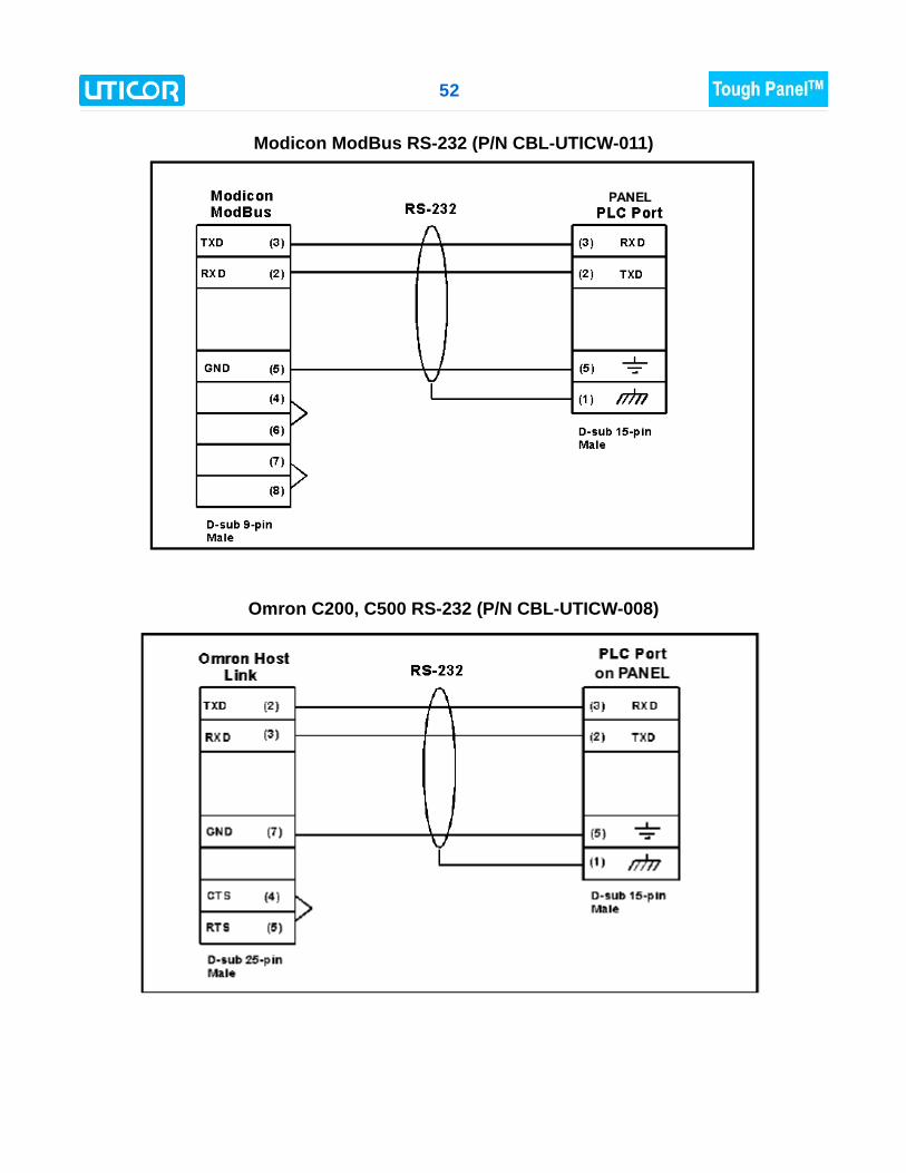
Modicon ModBus RS-232 (P/N CBL-UTICW-011)
Omron C200, C500 RS-232 (P/N CBL-UTICW-008)
53
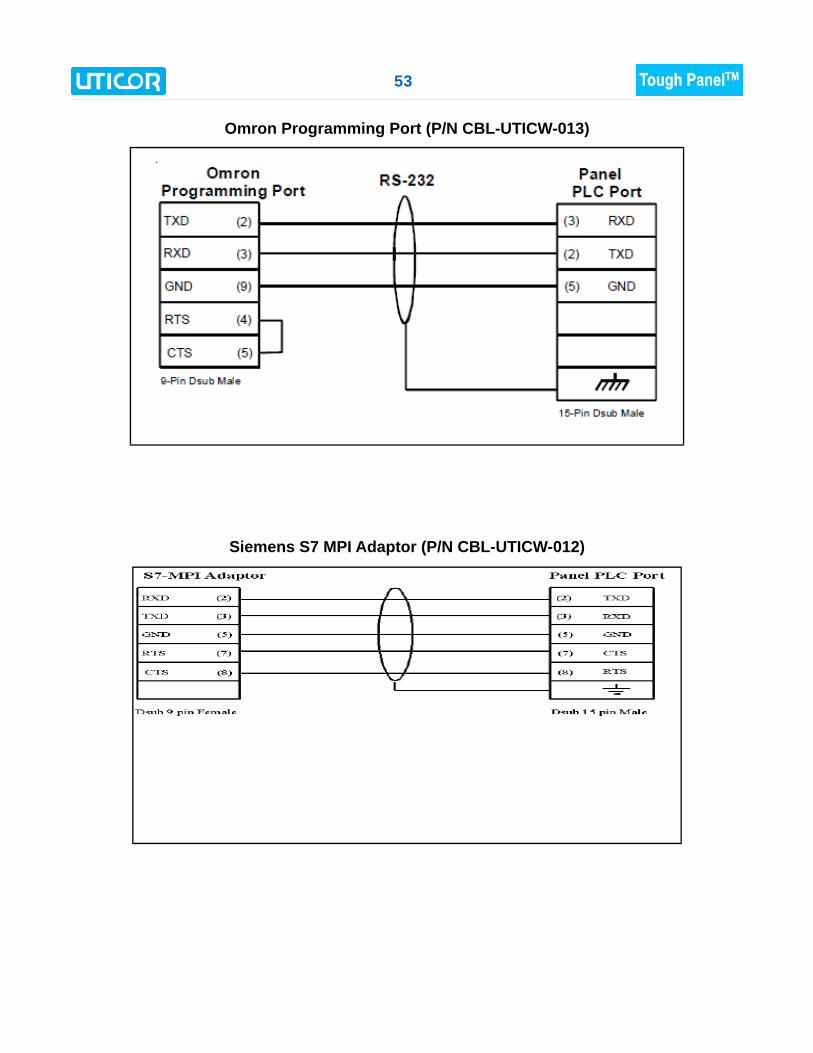
Omron Programming Port (P/N CBL-UTICW-013)
Siemens S7 MPI Adaptor (P/N CBL-UTICW-012)
54
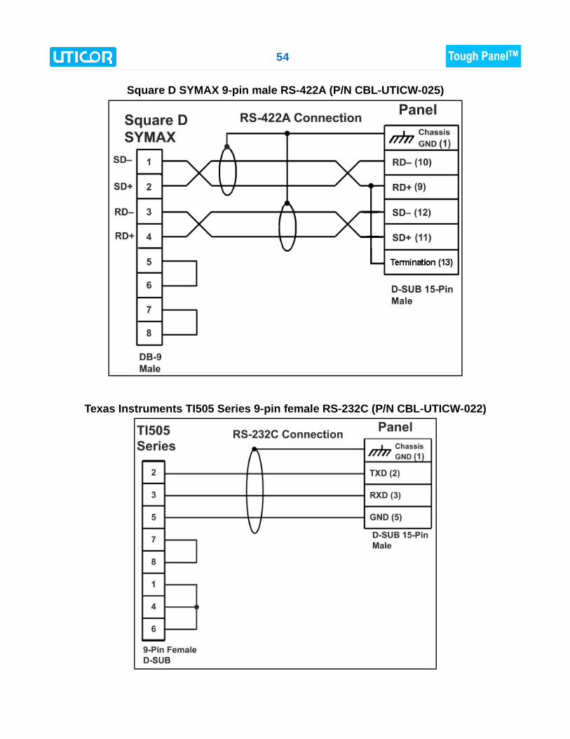
Square D SYMAX 9-pin male RS-422A (P/N CBL-UTICW-025)
Texas Instruments TI505 Series 9-pin female RS-232C (P/N CBL-UTICW-022)
55
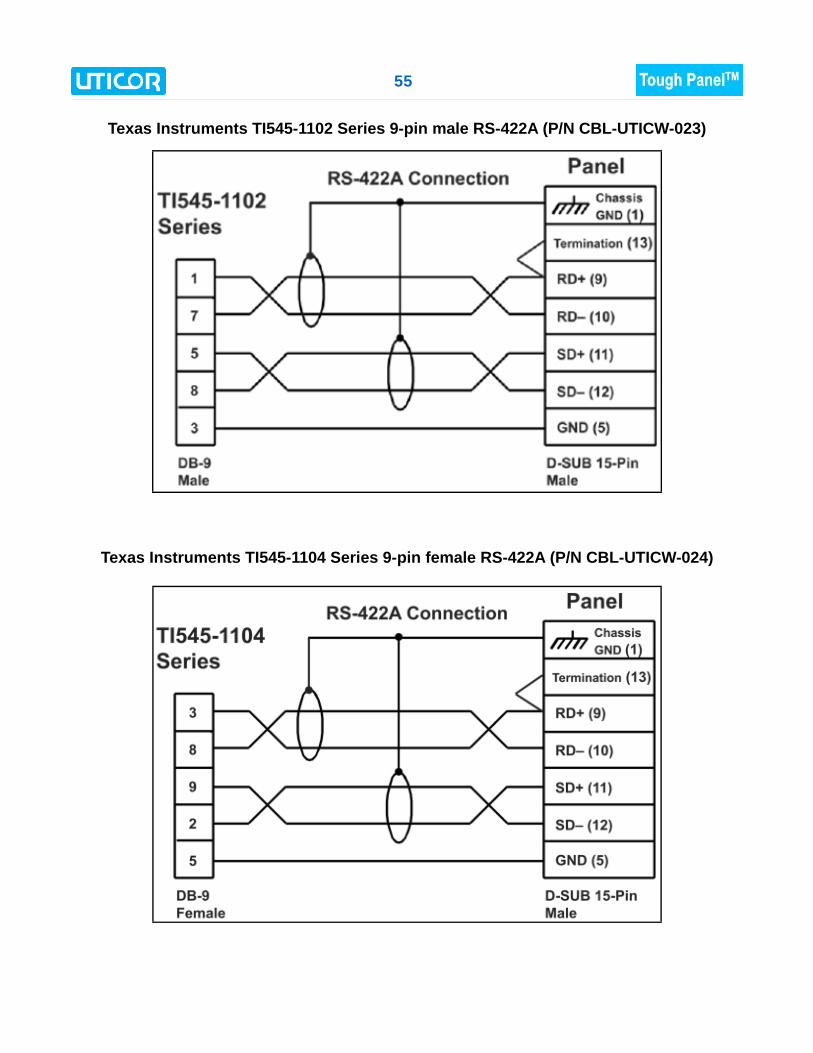
Texas Instruments TI545-1102 Series 9-pin male RS-422A (P/N CBL-UTICW-023)
Texas Instruments TI545-1104 Series 9-pin female RS-422A (P/N CBL-UTICW-024)
56
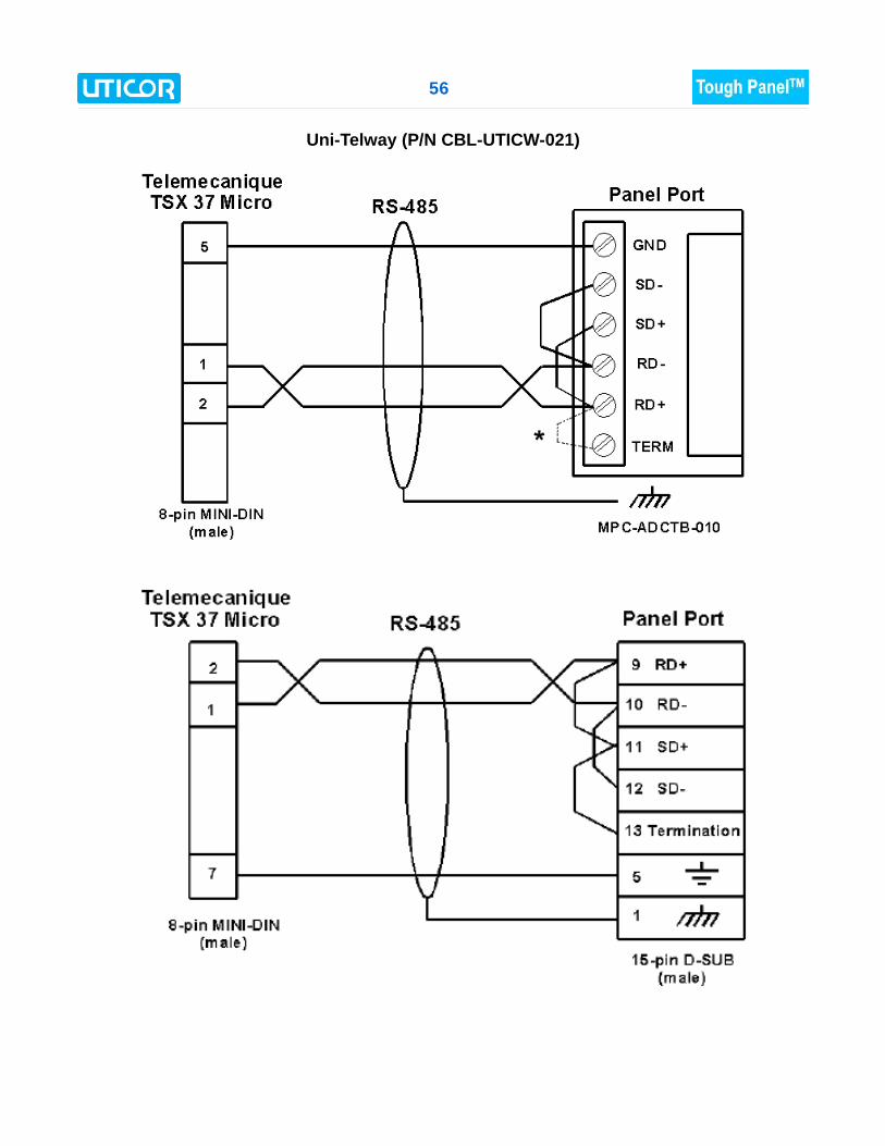
Uni-Telway (P/N CBL-UTICW-021)
57
Appendix B: Option Card InstallationMost ToughPanel units (6” PVP700 and larger) have the potential for expansion with option cards forcommunication with particular industrial networks as well as over the Internet. Option Cards by letter designation in ToughPanel P/N:
C – Mitsubishi CCLinkD – DeviceNetH – DH+ and Remote I/OM – Modbus PlusP – ProfibusN – Netview-Control and Data Storage
OPTION CARD INSTALLATION – GENERAL INSTRUCTIONS If you have ordered an option card to install in your ToughPanel, it would be shipped withall the hardware required to install it:
1. The circuit board for the particular communications option you requested2. Screws (6-32x½ & self tapping M3x8)3. Instruction sheet for installation in the ToughPanel
To install your option card, follow these steps: 1. Backup your user program
Before installing your card, please backup your user program using your uWin08software. Use the “Read from Panel and edit offline” button in the opening dialogbox to read back the panel program and save it on your PC. Then power down theToughPanel.
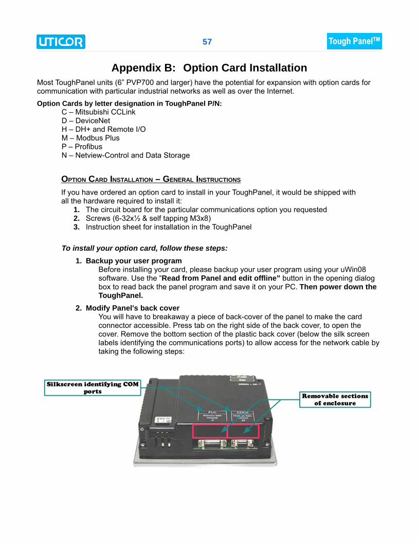
2. Modify Panel's back coverYou will have to breakaway a piece of back-cover of the panel to make the cardconnector accessible. Press tab on the right side of the back cover, to open thecover. Remove the bottom section of the plastic back cover (below the silk screenlabels identifying the communications ports) to allow access for the network cable bytaking the following steps:
Removable sections
of enclosure
Silkscreen identifying COM
ports
58
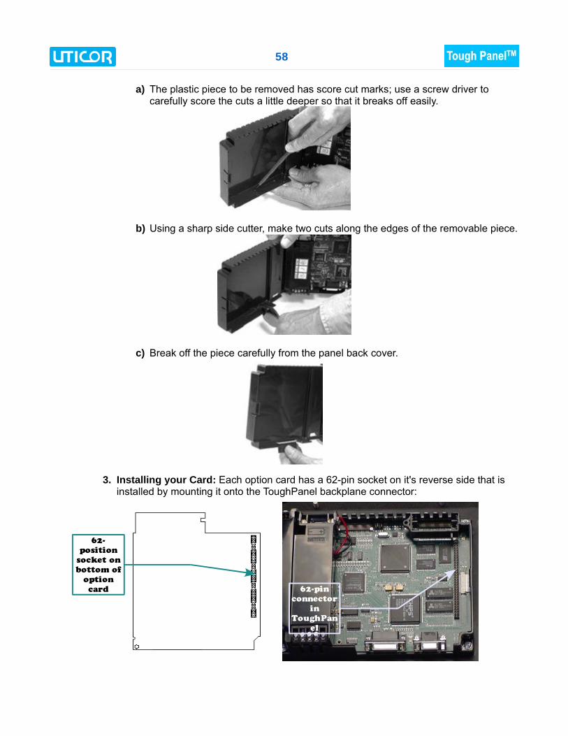
a) The plastic piece to be removed has score cut marks; use a screw driver tocarefully score the cuts a little deeper so that it breaks off easily.
b) Using a sharp side cutter, make two cuts along the edges of the removable piece.
c) Break off the piece carefully from the panel back cover.
3. Installing your Card: Each option card has a 62-pin socket on it's reverse side that isinstalled by mounting it onto the ToughPanel backplane connector:
62-
position
socket on
bottom of
option
card 62-pin
connector
in
ToughPan
el
59
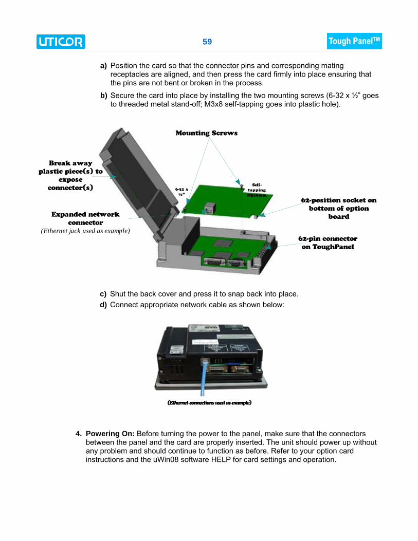
a) Position the card so that the connector pins and corresponding matingreceptacles are aligned, and then press the card firmly into place ensuring thatthe pins are not bent or broken in the process.
b) Secure the card into place by installing the two mounting screws (6-32 x ½” goesto threaded metal stand-off; M3x8 self-tapping goes into plastic hole).
c) Shut the back cover and press it to snap back into place. d) Connect appropriate network cable as shown below:
4. Powering On: Before turning the power to the panel, make sure that the connectorsbetween the panel and the card are properly inserted. The unit should power up withoutany problem and should continue to function as before. Refer to your option cardinstructions and the uWin08 software HELP for card settings and operation.
Mounting Screws
Break away
plastic piece(s) to
expose
connector(s)
62-position socket on
bottom of option
board
62-pin connector
on ToughPanel
Expanded network
connector
(Ethernet jack used as example)
(Ethernet connections used as example)
Self-
tapping
M3x8mm
6-32 x
½”

60
Generic DeviceNet I/O Option Card
The DeviceNet I/O Option Card has a 5-position, socket connector that is accessible from thebottom of the unit. Next to the connector are DIP Switches and then four LEDs that illuminate toindicate status. The Watchdog LED is only visible when you open the back cover.
The 5-pin Phoenix connector has a plug-in terminal block for wiring to the board. It is shown inplace in the PCB drawing above.
Connector Pin Signal Description
1 V- Negative Supply Voltage
2 CAN_L CAN_L bus line
3 SHIELD Cable shield
4 CAN_H CAN_H bus line
5 V+ Positive Supply voltage
DeviceNet card installed in Standard ToughPanel
Terminal Block connector
Pin
1
Socket on PCB
61
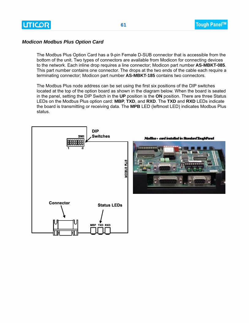
Modicon Modbus Plus Option Card
The Modbus Plus Option Card has a 9-pin Female D-SUB connector that is accessible from thebottom of the unit. Two types of connectors are available from Modicon for connecting devicesto the network. Each inline drop requires a line connector; Modicon part number AS-MBKT-085.This part number contains one connector. The drops at the two ends of the cable each require aterminating connector; Modicon part number AS-MBKT-185 contains two connectors.
The Modbus Plus node address can be set using the first six positions of the DIP switcheslocated at the top of the option board as shown in the diagram below. When the board is seatedin the panel, setting the DIP Switch in the UP position is the ON position. There are three StatusLEDs on the Modbus Plus option card: MBP, TXD, and RXD. The TXD and RXD LEDs indicatethe board is transmitting or receiving data. The MPB LED (leftmost LED) indicates Modbus Plusstatus.
ModBus+ card installed in Standard ToughPanel
62
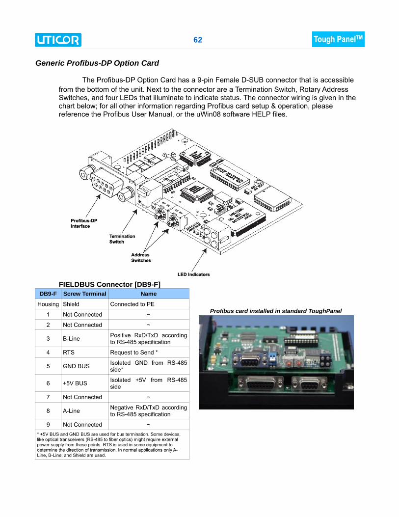
Generic Profibus-DP Option Card
The Profibus-DP Option Card has a 9-pin Female D-SUB connector that is accessiblefrom the bottom of the unit. Next to the connector are a Termination Switch, Rotary AddressSwitches, and four LEDs that illuminate to indicate status. The connector wiring is given in thechart below; for all other information regarding Profibus card setup & operation, pleasereference the Profibus User Manual, or the uWin08 software HELP files.
FIELDBUS Connector [DB9-F]DB9-F Screw Terminal Name
Housing Shield Connected to PE
1 Not Connected ~
2 Not Connected ~
3 B-Line Positive RxD/TxD accordingto RS-485 specification
4 RTS Request to Send *
5 GND BUS Isolated GND from RS-485side*
6 +5V BUS Isolated +5V from RS-485side
7 Not Connected ~
8 A-Line Negative RxD/TxD accordingto RS-485 specification
9 Not Connected ~* +5V BUS and GND BUS are used for bus termination. Some devices,like optical transceivers (RS-485 to fiber optics) might require externalpower supply from these points. RTS is used in some equipment todetermine the direction of transmission. In normal applications only A-Line, B-Line, and Shield are used.
Profibus card installed in standard ToughPanel
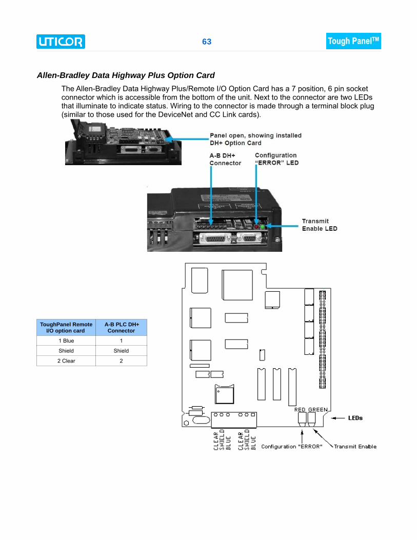
63
Allen-Bradley Data Highway Plus Option CardThe Allen-Bradley Data Highway Plus/Remote I/O Option Card has a 7 position, 6 pin socketconnector which is accessible from the bottom of the unit. Next to the connector are two LEDsthat illuminate to indicate status. Wiring to the connector is made through a terminal block plug(similar to those used for the DeviceNet and CC Link cards).
ToughPanel RemoteI/O option card
A-B PLC DH+Connector
1 Blue 1
Shield Shield
2 Clear 2
64
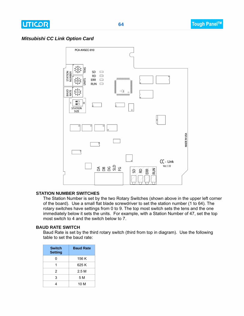
Mitsubishi CC Link Option Card
STATION NUMBER SWITCHESThe Station Number is set by the two Rotary Switches (shown above in the upper left cornerof the board). Use a small flat blade screwdriver to set the station number (1 to 64). Therotary switches have settings from 0 to 9. The top most switch sets the tens and the oneimmediately below it sets the units. For example, with a Station Number of 47, set the topmost switch to 4 and the switch below to 7.
BAUD RATE SWITCHBaud Rate is set by the third rotary switch (third from top in diagram). Use the followingtable to set the baud rate:
SwitchSetting
Baud Rate
0 156 K
1 625 K
2 2.5 M
3 5 M
4 10 M
65
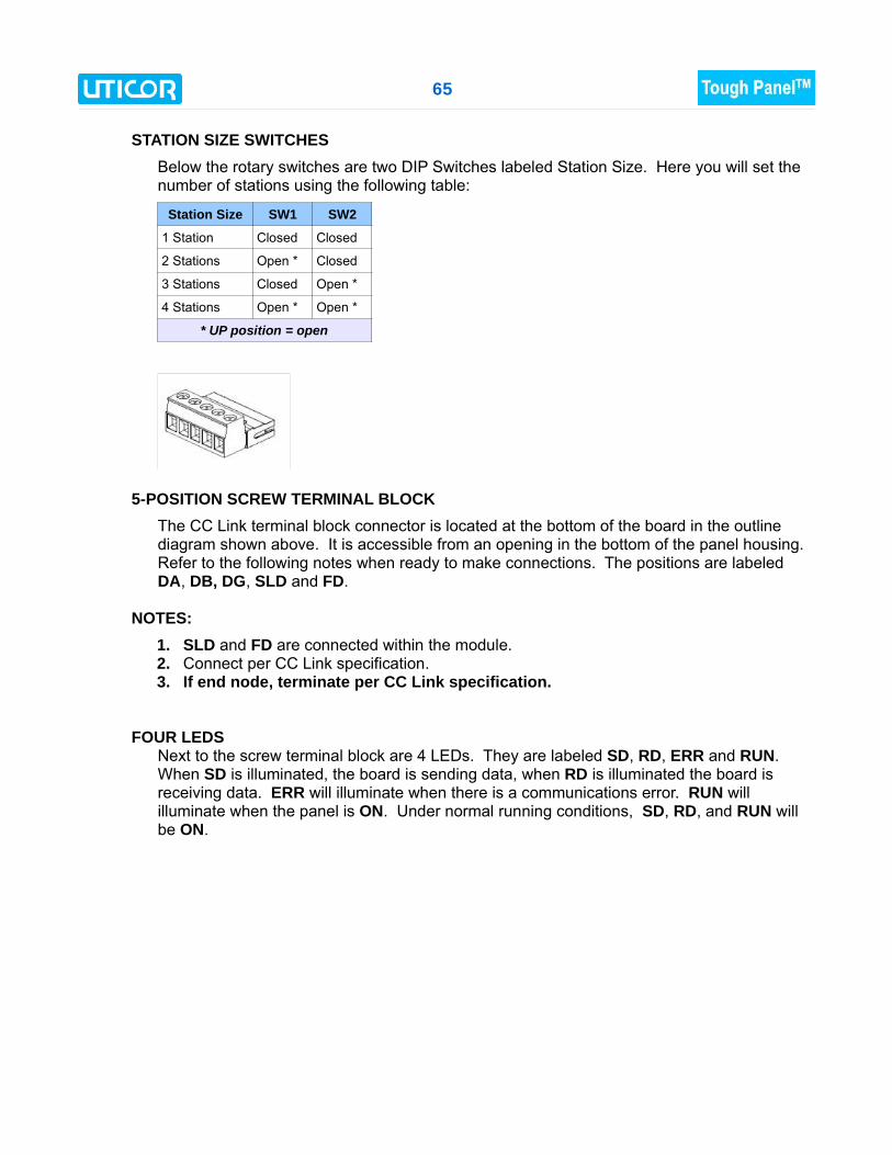
STATION SIZE SWITCHESBelow the rotary switches are two DIP Switches labeled Station Size. Here you will set thenumber of stations using the following table:
Station Size SW1 SW2
1 Station Closed Closed
2 Stations Open * Closed
3 Stations Closed Open *
4 Stations Open * Open *
* UP position = open
5-POSITION SCREW TERMINAL BLOCKThe CC Link terminal block connector is located at the bottom of the board in the outlinediagram shown above. It is accessible from an opening in the bottom of the panel housing.Refer to the following notes when ready to make connections. The positions are labeledDA, DB, DG, SLD and FD.
NOTES:1. SLD and FD are connected within the module.2. Connect per CC Link specification.3. If end node, terminate per CC Link specification.
FOUR LEDSNext to the screw terminal block are 4 LEDs. They are labeled SD, RD, ERR and RUN.When SD is illuminated, the board is sending data, when RD is illuminated the board isreceiving data. ERR will illuminate when there is a communications error. RUN willilluminate when the panel is ON. Under normal running conditions, SD, RD, and RUN willbe ON.
66
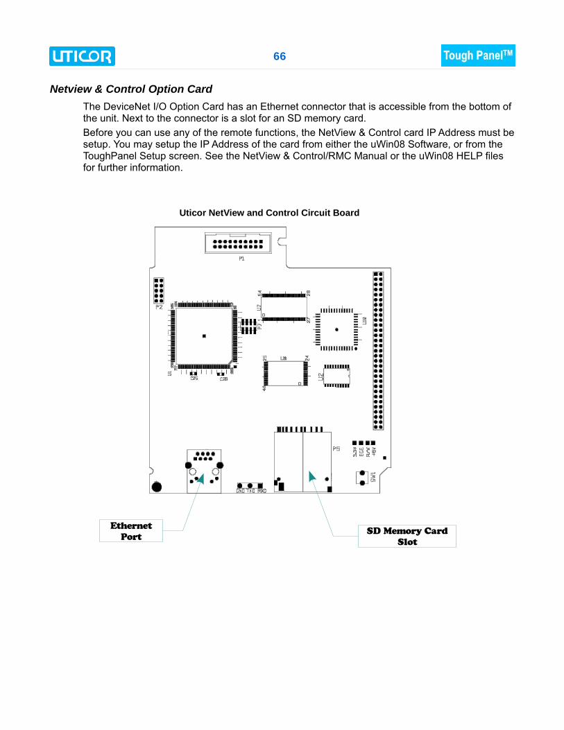
Netview & Control Option CardThe DeviceNet I/O Option Card has an Ethernet connector that is accessible from the bottom ofthe unit. Next to the connector is a slot for an SD memory card. Before you can use any of the remote functions, the NetView & Control card IP Address must besetup. You may setup the IP Address of the card from either the uWin08 Software, or from theToughPanel Setup screen. See the NetView & Control/RMC Manual or the uWin08 HELP filesfor further information.
Uticor NetView and Control Circuit Board
Ethernet
PortSD Memory Card
Slot