Embed Size (px)
Citation preview

Design Automation for Embedded Systems 3, 117–148 (1998)c© 1998 Kluwer Academic Publishers. Manufactured in The Netherlands.
Hardware-Software Prototyping from LOTOS
LUIS SANCHEZ FERNANDEZDep. Tecnologıas Comunicaciones, Univ. Carlos III Madrid, E-28911 Leganes/Madrid, Spain
GERNOT KOCHForschungszentrum Informatik (FZI), Haid-und-Neu-Straße 10-14, D-76131 Karlsruhe, Germany
NATIVIDAD MART INEZ MADRIDDep. Tecnologıas Comunicaciones, Univ. Carlos III Madrid, E-28911 Leganes/Madrid, Spain
MARIA LUISA L OPEZ VALLEJODep. Ing. Electronica (DIE), ETSIT, Univ. Polit. Madrid, E-28040 Madrid, Spain
CARLOS DELGADO KLOOSDep. Tecnologıas Comunicaciones, Univ. Carlos III Madrid, E-28911 Leganes/Madrid, Spain
WOLFGANG ROSENSTIELFZI and University of Tubingen, Sand 13, D-72076 Tubingen, Germany
Abstract. In this paper we present an extension to the co-design approach based on LOTOS presented in FourthInternational Workshop on Hardware-Software Co-Design, 1996. In this new version we add a prototyping stage toour design flow, that allows to validate the design at the implementation level. We present the complete approach,stressing the prototyping stage after partitioning. An example of an Ethernet bridge serves us to illustrate ourapproach and present some results.
Keywords: LOTOS, system-level design, co-design, prototyping
1. Introduction
Over the last few years, the level of abstraction applied to the description and design ofhardware systems has risen. Initially, descriptions were based at the circuit level. Sincethen, description styles have moved to gate, register transfer (RTL) and behavioural level.We will follow the convention that, at the higher levels of abstraction, the wordspecificationwill be used instead ofdescription. A specification denotes an abstraction. It representswhat the system should do, not how it should do.
This move to higher levels of abstraction is a consequence of a number of factors. Ahigher level of abstraction allows the designer to reduce the time spent in specificationbecause he/she does not need to take care of low-level implementation details. In high-level specifications the functionality of the system is clearer, allowing for a more extensiveexploration of the design space. The improved ability to detect (and correct) design errors in
118 SANCHEZ FERNANDEZ ET AL.
early phases of the design process—testing the design takes less time because the number ofobjects in the specification is lowered by an order of magnitude—is also a significant factor.Also, this early testing reduces the number of errors to be detected at the implementationlevel and thus the effort to be spent there.
There is a growing awareness of high-level specification languages in system-level hard-ware design. The interested reader is referred to [2] for details of some of the differentformalisms currently being explored. The software design world experienced an analogousphenomenon in the recent past, but the process is still ongoing in the hardware designfield.
Hardware-software co-design is a new design technique that aim at an integrated designof hardware and software components of embedded systems. Which is the best specificationstyle for co-design is still an open issue. The co-design approaches presently available makeuse of a broad set of specification styles. Some of them start with implementation orientedlanguages in the style of C or VHDL [7, 9, 27]. Others use state-oriented specificationlanguages [8].
Some other approaches also use high-level specification languages provided with a well-founded formal semantics [1, 3, 4, 12, 24]. Apart from the points mentioned above, a high-level specification language for co-design has the advantage of allowing for a fair assignmentof components, without being biased towards software or hardware realizations—as inthe case of C or VHDL-like languages. In the work described in [1], UNITY is used asspecification language. This work concentrates on the partitioning aspects of co-design.The specification of hardware, software and interface components described in [24], isbased on FOCUS. FOCUS is a framework for the specification and development of systemsbased on streams. Neither [1] nor [24] provide a complete co-design flow from specificationto prototyping. Two other approaches [4, 12] offer co-design systems that accept high-levelspecification languages as input (ESTEREL and SDL, respectively).
A co-design methodology based on the formal description technique LOTOS [11] hasbeen developed in the ESPRIT project COBRA. In this paper the design flow presentedin [3] is extended with a prototyping stage. A worked example is used to illustrate theextended design flow and present some results.
The layout for the rest of the paper is as follows. Section 2 is devoted to introducethe LOTOS language and Section 3 to show why LOTOS is better specification languagethan commonly used languages for many applications. Section 4 presents the LOTOSdesign flow. Section 5 presents the prototyping environment developed in the COBRAproject. Section 6 describes the process of deriving a prototype from the partitioning ob-tained. Section 7 presents the worked example. We conclude with a discussion of the resultsobtained.
2. LOTOS
LOTOS (ISO standard IS-8807) is a system-level specification language that supports con-currency, synchronisation, composition of processes and nondeterminism. The languagesupports a wide range of abstraction levels, from algebraic specifications to algorithmic-styleversions. The standard also includes a formal semantics, and therefore formal refinement
HARDWARE-SOFTWARE PROTOTYPING FROM LOTOS 119
and verification of LOTOS specifications are possible. LOTOS was originally designed forthe specification of computer protocols, but it can also model any concurrent system; it isespecially well suited to control-oriented applications. Translators from LOTOS to C [17](TOPO) and to synthesisable VHDL [6] (HARPO) are currently available. In the rest ofthis section we will survey the LOTOS language. More information about LOTOS can befound in [6, 25].
System behaviour in LOTOS is defined by giving the possible sequences of interactionsbetween the system and its environment. In contrast with other languages (for instance, C),where the behaviour of the system is defined by an algorithm that describes the internalcomputations that are performed in the system, in LOTOS we see the system as a blackbox, and we only define the behaviour of the system as seen by an external observer.
A system and its components are represented in LOTOS byprocesses. A process interactswith its environment viagates. A gate models a logical or physical attachment point betweena system and its environment. The external observer can try to interact with a systemdescribed in LOTOS through one of its gates. This interaction can be accepted or notaccepted by the system. A LOTOS description defines which are the possible sequencesof interaction accepted by the system. In the case that a LOTOS process is a component ofthe global system, its environment is formed by the other LOTOS processes that interactwith it plus the external observer.
The units of interaction between any LOTOS process and its environment are calledeventsor actions. Events are atomic in the sense that they occur instantaneously, withoutconsuming time. An event is an abstraction of a communication that takes place betweentwo or more entities. An entity may be either a LOTOS process or the external observer. Anevent can represent different communication mechanisms, ranging from simple read/writeoperations through complex communication protocols depending on the abstraction level ofthe specification. The communication is symmetric in the sense that all the entities involvedin an event (including the external observer if the event is externally observable) must agreeon performing it. When several LOTOS processes agree to communicate through a commongate (i.e., to perform an event), we say that these processessynchroniseat that gate. Duringan event, data can be exchanged between the entities that take part in it.
The usual graphical representation of the behaviour of a LOTOS process is a tree thatdefines the possible sequences of events accepted by the LOTOS process (as the tracesthrough the tree from the root).
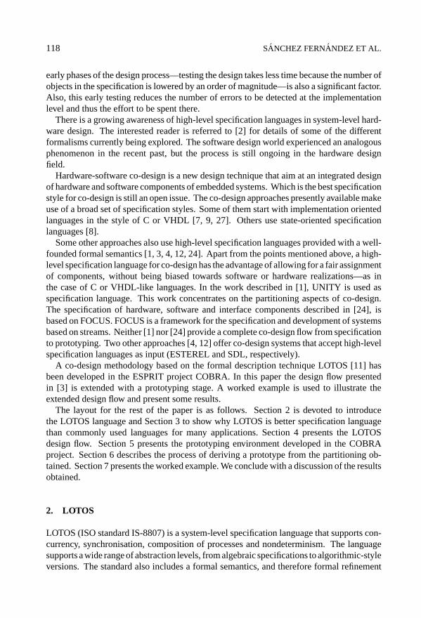
Figure 1 represents a LOTOS process named P1 (left side) and a graphical representationof its behaviour as a tree of accepted events (right side). This process has three gates, labelleda, b andc. At the beginning the process accepts a communication with its environmentthrough gatea (that is, accepts an event at gatea) or gateb. If the process and its environmentagree to communicate through gatea, then the process will next accept two communica-tions through gatec (accept two consecutive events in gatec) and then will not acceptany further communication with its environment. If the process and its environment agreeto communicate through gateb, then the process will next accept two communicationsthrough gatea and then will not accept any further communication with its environment.Remember that each event represents an atomic communication (at the specified abstractionlevel) between the process and its environment. In the example in figure 1 the behaviour ofthe LOTOS process is finite. Later we will see how to define infinite LOTOS behaviours.

120 SANCHEZ FERNANDEZ ET AL.
Figure 1. A LOTOS process and its behaviour tree.
Also, in this example no data is exchanged between the process and its environment. Theprocess and its environment only interact in order to synchronise each other. How data canbe exchanged between a process and its environment will also be explained later.
LOTOS processes are defined by giving its name, the gates that define the interface be-tween the process and its environment, and a behaviour expression. A behaviour expressionis the description of the behaviour of a LOTOS process. An example of a LOTOS processis given below. This LOTOS process implements the behaviour of the process presented infigure 1.
PROCESS P1 [a, b, c] : noexit:=(a; b; c; stop)[](b; a; a; stop)
ENDPROC
The first line declares the name of the process (P1) and its gates (a,b,c). Thenoexitkeyword is used to indicate that this process will not successfully terminate, but this is notimportant for the LOTOS overview we are going to give here. The next three lines formthe behaviour expression that defines the behaviour of processP1. The last line indicatesthat the definition of the process has finished.
Let us take another look at figure 1. As we have already said, in its initial state processP1 accepts an event at gatea or an event at gateb. What does that mean exactly? First,it is not possible that both events happen. In the semantics of LOTOS it is forbidden thattwo events happen simultaneously. That is, in LOTOS events are temporally ordered oneafter the other (in fact, LOTOS stands for Language Of Temporal Ordering Specification).Therefore, if one of them happens the other branch of the behaviour tree is deleted and canno longer be executed. How can it be known which of the events would be executed? Thisdepends on the environment. The environment of the process can accept one of the events,none or both of them. In the first case, the event accepted by the environment is the one
HARDWARE-SOFTWARE PROTOTYPING FROM LOTOS 121
executed. In the second case, no event can be executed. This situation (no further eventcan be executed) is named deadlock. In the third case one of the possible events will benondeterministically chosen.
We have already introduced the concepts of event, synchronisation, nondeterminismand deadlock. In the rest of this section we present the main elements of the LOTOSlanguage.
2.1. Basic LOTOS
Basic LOTOS is a subset of LOTOS in which events do not carry data. They are usedjust to synchronise the processes with their environment. The first element of the LOTOSlanguage that we are going to present is the completely inactive process. It is namedstop,and it cannot accept any event from its environment.
A number of operators are available in LOTOS to combine LOTOS behaviour expressionsinto new ones. Using these operators complex behaviour expressions can be built up. Thefirst operator that we are going to present is the action prefix. An action prefix allows toprepend an action to a behaviour expression. Given a behaviour expressionB and a gateg,the behaviour expressiong ; B is equivalent to first an event in gateg and then the behaviourdefined byB. It is possible to prepend an internal event also (an event that cannot be seenfrom the process environment). This is done by using the reserved wordi instead of a gatename (i.e.,i ; B).
A second operator is nondeterministic choice. This operator allows to combine twobehaviour expressions to get a new one that is equivalent either to the behaviour defined bythe first behaviour expression or the behaviour defined by the second one. It is representedby B1 [ ] B2, whereB1 andB2 are the two LOTOS behaviour expressions that are beingnondeterministically composed.
With the basic processstop and the two operators we have just presented we are readyto understand the LOTOS behaviour expression that describe the behaviour of the system(in figure 1), that we have already seen.
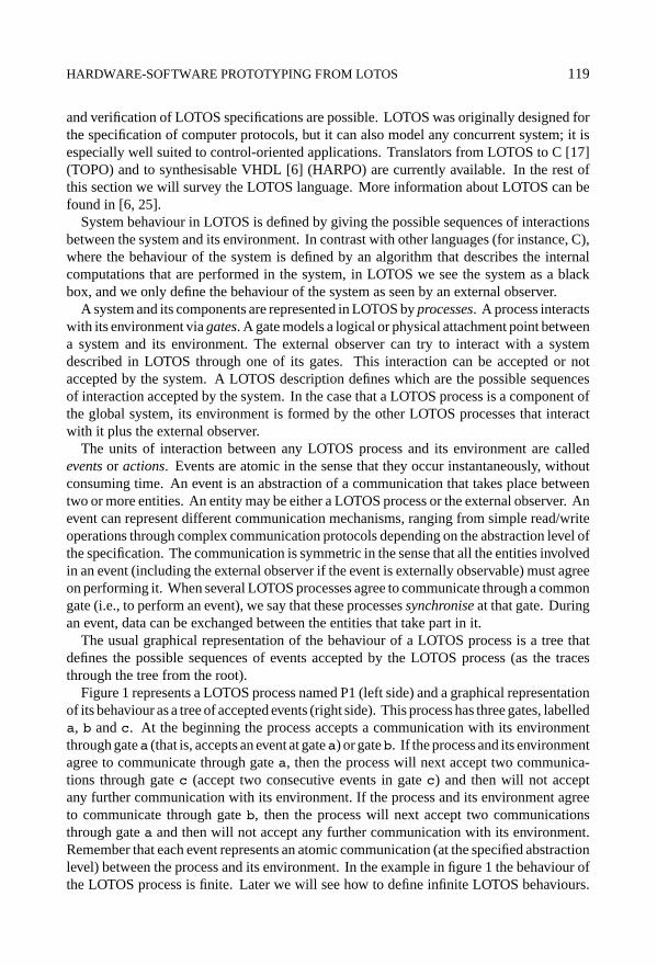
We see an example of another LOTOS behaviour expression and its corresponding eventtree in figure 2.
This behaviour expression in figure 2 initially can accept an event on gateb or candecide to execute an internal event. Suppose that the environment can accept an event ongateb. What would happen? Remember that in Section 2 we said that when two eventswere possible in a process one of them is nondeterministically chosen. It may happen thateven if the environment accepts an event on gateb the process decides to execute theinternal event. Therefore, an external observer would find that sometimes this process startsaccepting an event on gateb and sometimes does not. This kind of behaviour expressionscan be used to model for instance timeouts (the timeout is represented by the internalevent).
Another group of LOTOS operators are those that are used to model two entities thatsynchronise with each other. The most general LOTOS synchronisation operator is of theform B1 | [g1, . . . , gn] | B2, whereg1, . . . , gn is the set of gates in which the behaviourexpressionsB1 andB2 are synchronised. Let S be the set of gatesg1, . . . , gn. The events

122 SANCHEZ FERNANDEZ ET AL.
(i; a; c; c; stop)
[]
(b; a; a; stop)
Figure 2. A behaviour expression with internal events.
accepted by this LOTOS behaviour expression are:
• If an event is accepted inB1at a gate that is not in S then this event would also be acceptedin B1 | [g1, . . . , gn] | B2.• If an event is accepted inB2at a gate that is not in S then this event would also be accepted
in B1 | [g1, . . . , gn] | B2.• If an event is accepted inB1and inB2at a gate that is in S then this event would also be
accepted inB1 | [g1, . . . , gn] | B2.
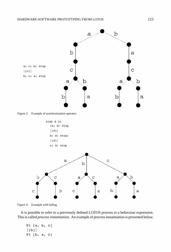
If none of the above, then the event would not take place. An example of a LOTOSbehaviour expression with the synchronisation operator can be found in figure 3.
There are two additional synchronisation operators that are particular cases of the one wehave just presented. The full synchronisation operator (represented with| |) is used whenthe processes synchronise on all gates. The interleaving operator (represented with| | |) isused when the processes do not synchronise on any gate.
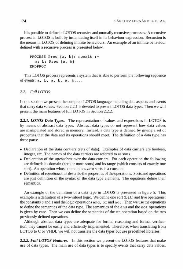
When defining the behaviour of a system it happens quite often that we need to representinternal channels that cannot be accessed from outside the system. We do this in LOTOSwith the hiding operator. The hiding operator hides the events that take place in the selectedgates from the environment of a LOTOS behaviour expression, and therefore the eventsat these gates become internal events from the point of view of an external observer. Anexample can be found in figure 4.
There are other two LOTOS operators in basic LOTOS. One operator (enabling) is usedto model a process that is executed after the successful termination of another. The otheroperator (disabling) is used to model a LOTOS process that is interrupted by another.
HARDWARE-SOFTWARE PROTOTYPING FROM LOTOS 123
a; c; b; stop
|[c]|
b; c; a; stop
Figure 3. Example of synchronisation operator.
hide d in
(a; d; stop
|[d]|
b; d; stop)
|[d]|
c; d; stop
Figure 4. Example with hiding.
It is possible to refer to a previously defined LOTOS process in a behaviour expression.This is calledprocess instantiation. An example of process instantiation is presented below.
P1 [a, b, c]|[b]|P1 [b, a, c]
124 SANCHEZ FERNANDEZ ET AL.
It is possible to define in LOTOS recursive and mutually recursive processes. A recursiveprocess in LOTOS is built by instantiating itself in its behaviour expression. Recursion isthe means in LOTOS of defining infinite behaviours. An example of an infinite behaviourdefined with a recursive process is presented below.
PROCESS Prec [a, b]: noexit :=a; b; Prec [a, b]
ENDPROC
This LOTOS process represents a system that is able to perform the following sequenceof events:a, b, a, b, a, b, . . .
2.2. Full LOTOS
In this section we present the complete LOTOS language including data aspects and eventsthat carry data values. Section 2.2.1 is devoted to present LOTOS data types. Then we willpresent the main features of full LOTOS in Section 2.2.2.
2.2.1. LOTOS Data Types.The representation of values and expressions in LOTOS isby means of abstract data types. Abstract data types do not represent how data valuesare manipulated and stored in memory. Instead, a data type is defined by giving a set ofproperties that the data and its operations should meet. The definition of a data type hasthree parts:
• Declaration of thedata carriers(sets of data). Examples of data carriers are boolean,integer, etc. The names of the data carriers are referred to as sorts.• Declaration of theoperationsover the data carriers. For each operation the following
are defined: its domain (zero or more sorts) and its range (which consists of exactly onesort). An operation whose domain has zero sorts is a constant.• Definition ofequationsthat describe the properties of the operations. Sorts and operations
are just definition of the syntax of the data type elements. The equations define theirsemantics.
An example of the definition of a data type in LOTOS is presented in figure 5. Thisexample is a definition of a two-valued logic. We define one sort (bit) and five operations:the constants0 and1 and the logic operationsand, or andnot. Then we use the equationsto define the semantics of the data type. The semantics of theand and thenot operationsis given by case. Then we can define the semantics of theor operation based on the twopreviously defined operations.
Although abstract data types are adequate for formal reasoning and formal verifica-tion, they cannot be easily and efficiently implemented. Therefore, when translating fromLOTOS to C or VHDL we will not translate the data types but use predefined libraries.
2.2.2. Full LOTOS Features. In this section we present the LOTOS features that makeuse of data types. The main use of data types is to specify events that carry data values.

HARDWARE-SOFTWARE PROTOTYPING FROM LOTOS 125
TYPE Bit op IS
SORTS bit
OPNS
0 : -> bit
1 : -> bit
and : bit,bit -> bit
or : bit,bit -> bit
not : bit -> bit
EQNS forall b1,b2,b3: bit ofsort bit
and(1,1) = 1;
and(0,1) = 0;
and(1,0) = 0;
and(0,0) = 0;
not(1) = 0;
not(0) = 1;
or(b1,b2) = not(and(not(b1),not(b2)));
ENDTYPE
Figure 5. Example of a data type definition in LOTOS.
LOTOS gates are not typed, and therefore we can have an event at a LOTOS gate carrying aboolean and later another event at the same LOTOS gate carrying an integer. Nevertheless,in practice events at a gate usually are always of the same type (in particular, this is requiredin the subset of LOTOS that is supported by HARPO). An event can only take place if allthe LOTOS processes involved in the event (and the environment if the gate is not hidden)agree on the sort and value of the data carried by the event.
The action prefix presented in Section 2.1 will now be extended so that actions are allowedto carry data information. There are two possibilities:value declarationand variabledeclaration. The first case is of the formg !e;. g is the name of the gate where the eventis taking place as we did in Section 2.1.e is an expression which defines the value (andtherefore the sort) that is imposed and that should be carried by the event. An example ofaction prefix with value declaration isb !1;. In the case of variable declaration the actionprefix is of the formg ?x: sort;. x is the name of a variable of sortsort. In this case, theprocess is able to accept an event that carries a data of sortsort in gateg whatever the data is.If the event takes place the value of the data being carried is stored in the variable. This valuecan be later used by the LOTOS process. An example of variable declaration isb ?x: bit;.
There can be from 0 toN processes involved in a LOTOS event performing an actionof kind value declaration. The same can be said with respect to actions of kind variabledeclaration. Of course, at least one process should be present. If no process forces avalue in the event (no action of kind value declaration is present), the value exchanged isnondeterministically chosen. If several processes try to impose a value, all of them mustoffer the same value. Otherwise the event will not be performed.
It may be the case that we do not want to impose a single value on an event but a rangeof values. This can be done by means of selection predicates. A selection predicate isa condition that is attached to a variable declaration and that should be met by the event.
126 SANCHEZ FERNANDEZ ET AL.
An action prefix with a selection predicate has the formg ?x: sort [ P]; whereP is thepredicate that should be met. An example isb ?x: integer [x gt 0];.
When a process reads a value in a variable declaration we might also want to make thebehaviour of the process depend on the value read. This can be done by means of guards.A guard means that a behaviour expression can only be executed when the predicate insidethe guard is satisfied. Guards are of the form [P] −> B whereP is the predicate of theguard andB is the protected behaviour expression. As an example, the following LOTOSbehaviour expression can be used to compute the absolute value of an integer:
a ?x: integer;(([x ge 0] -> b !x; stop)[]([x lt 0] -> b !-x; stop))
In the example abovege is thegreater than or equalrelational operator andlt is theless thanrelational operator.
We can also have processes with parameters. In this case the value of the parametersis defined when the process is instantiated. This is useful, for instance, when we have arecursive process and we want to maintain some values between one instantiation of theprocess and another. The following example is a LOTOS process that outputs the naturalnumbers (supposing that it is initially instantiated with its parameter set to 0.
PROCESS naturals [a] (n: integer): noexit:=a !n; naturals [a] (n+1)
ENDPROC
2.3. LOTOS Subsets Supported by TOPO and HARPO
At this point we have completed the discussion of the LOTOS language as it is defined inthe standard. The specification of systems to be implemented partly in software and partlyin hardware has to take into account some restrictions and features of the translators fromLOTOS to C and VHDL (specially). In this section we are going to present these features.
TOPO (the translator from LOTOS to C we are using) supports almost all the LOTOSlanguage. It has a few limitations. Specifications that may generate an unbounded numberof processes may cause a run-time error. If the data types are translated automatically, theequations must be interpretable as a rewrite system: the left-hand sides of the equations arenames for patterns that can be substituted in the right-hand sides. Nevertheless, automat-ically generated data types are very inefficient, so we use hand-coded libraries, which arealso supported by TOPO.
With respect to the performance of the C generated by TOPO, it should be taken intoaccount that the parallel operators (although fully supported) are not as efficiently im-plemented as the action prefix and choice operators. This should not be surprising for asoftware implementation. As a consequence, before implementing the software part of oursystem we collapse all the processes into one to get better performance results.

HARDWARE-SOFTWARE PROTOTYPING FROM LOTOS 127
HARPO supports a smaller subset of LOTOS:
• LOTOS allows dynamic creation of processes. This is not supported by HARPO. HARPOneeds to identify a static architecture of processes to be able to translate the LOTOSspecification to VHDL. Recursive process instantiation is supported, providing that thestatic architecture is not changed.• LOTOS gates must be typed (the data carried through a LOTOS gate must be always of
the same sort). All the actions at a gate in a process should be of the same kind (valuedeclaration or variable declaration). Synchronisation is restricted to 1 toN (1 action ofkind value declaration andN of kind variable declaration).• The data types must be implemented in a VHDL library by hand.
3. Why LOTOS?
We have already mentioned some of the features of LOTOS that make it suitable as system-level specification language adequate for co-design: its high degree of abstraction andpowerful description features, it is not biased towards software or hardware and it possessesa standard formal semantics.
As LOTOS descriptions are based on the interaction between a system and its environ-ment, it is especially well suited to specifying systems that implement telecommunicationprotocols (in fact, LOTOS was designed to describe them). Nevertheless, there are manyother embedded systems that are suitable for specification in LOTOS. It happens quite of-ten that complex systems are composed of a set of subsystems that communicate amongthemselves by means of one or several complex protocols. This kind of systems can bevery well described in LOTOS, because the description of the behaviour of communicat-ing subsystems is much more simpler in LOTOS than in conventional system descriptionlanguages such as VHDL. As an example, the following code (taken from [5]) is a VHDLprocess that communicates with its environment by means of a handshaking protocol:
processbeginBUSY <= F0;wait until START = F1;BUSY <= F1;C := A + B;D <= C * E;wait until START = F0;
end process;
The same behaviour can be represented in LOTOS as follows:
PROCESS Example [gate a, gate b, gate d, gate e]: noexit :=gate a ?a: integer;gate b ?b: integer;

128 SANCHEZ FERNANDEZ ET AL.
gate e ?e: integer;gate d !(a + b) * e;Example [gate a, gate b, gate d, gate e]
ENDPROC
We can get rid ofBUSY, START and thewait statements, in charge of synchronisingthe process with its environment, because the synchronisation mechanism is abstracted inLOTOS.
When specifying a system that is going to be co-designed it is necessary to split itsbehaviour into several communicating subsystems. This is another aspect that make LOTOSsuitable as specification language for co-design.
4. LOTOS Co-Design Flow
The LOTOS design flow is illustrated in figure 6. Three different design stages are con-sidered, corresponding to three abstraction levels: system specification and refinement,hardware and software specification and hardware-software prototyping. In the remainderof this section we will sketch the design flow corresponding to the first two design stages.In Section 5 we present the prototyping environment and architecture we have used. Wedevote a separate section to the prototyping design stage (Section 6).
Figure 6. LOTOS design flow.
HARDWARE-SOFTWARE PROTOTYPING FROM LOTOS 129
4.1. System Specification
The high level of abstraction of LOTOS as a specification language allows us to avoidmaking assumptions about the implementation at early stages of the design process. Inthe specification phase, systems are not described by means of algorithms, but as a set ofproperties or axioms. This allows us to concentrate onwhatis to be designed rather than onhowit is going to be achieved. Algebraic specification techniques are well-known and forma standard part of languages such as LOTOS. They are used for the algebraic specificationof data; we will use them in the initial stage of the specification of whole systems.
The transition from the specification to the design involves the definition of an algorithmthat satisfies the desired properties, or in other words, one has to find a model for thealgebraic specification. Please note that the algebraic specification needs not specify aunique model (up to isomorphism); there might be several (non-isomorphic) models. Theonly requirement is that it is not inconsistent (i.e., has no contradictory axioms), whichwould imply that there is no model.
Therefore, the transition is a highly creative process, since it involves the definition ofan initial algorithm. The axioms, nevertheless, create a reference for checking it against.Some specifications can be very concrete and interpreted directly as algorithms, e.g., theinversion of a list:
inv:list→ list
inv(emptylist)= emptylist
inv(a & l) = inv(l) & a
But some might be very abstract, and require in addition strategies to make them run,e.g., the inversion of a matrix:
inv:matrix→ matrix
inv(a)× a = I
a× inv(a) = I
The first version of an algorithm might be easy to understand, but not efficiently im-plementable. Several refinements of the initial algorithm can be tried. Only the run-timeproperties of the implementation change from trial to trial and the abstract specification issatisfied in each case.
In general, there are two ways to check the correctness of an algorithm: testing viasimulation and formal proof. Both of them are available in LOTOS. There is currentlyavailable a tool, named LOLA [20], that allows the simulation of LOTOS specifications. Inaddition, the fact that LOTOS has been provided with a standard formal semantics allowsus to construct formal proofs using LOTOS specifications. LOLA can also be used for this(some formally correct transformations of specifications are supported).
LOTOS allows the designer to specify the behaviour of a system, but not non-functionalinformation such as throughput, cost, etc. We have extended LOTOS with annotations[21, 22] that allow the designer to specify the non-functional requirements together with theestimates and measures that will be obtained along the design process. After specification
130 SANCHEZ FERNANDEZ ET AL.
and refinement of a system, the next step is to enter into the LOTOS specification the desirednon-functional requirements.
4.2. Hardware-Software Specification
Once the system has been completely specified, both in its functional and non-functionalaspects, the next step is to assign each process in the specification to software or to hardwarein such a way that the final implementation will meet its non-functional requirements. Atthe end of this process we obtain two specifications, one for the part to be implemented insoftware and another for the part to be implemented in hardware.
In order to begin the partitioning process, some information is needed. Several parametersof the design will be used as inputs to the partitioning strategy. These parameters can beestimated either by a static or a dynamic analysis of the LOTOS code. By static analysis,we mean estimates obtained by means of a non-standard interpretation of the LOTOScode. By dynamic analysis, we mean the measures obtained by repeated execution of theimplementation or simulation of the specification.
The main parameters to be statically estimated are the area and the clock period of thehardware implementations for each LOTOS process. The parameters that will be calculateddynamically are: number of clock cycles spent in each component (obtained via RTLVHDL simulation), software execution time (obtained by profiling) and communicationcost (explained below).
For the hardware implementation, every LOTOS process is translated into a VHDLentity. This entity is composed of a finite state machine and a set of pre-synthesised librarycomponents. Area estimation is only needed for the finite state machine. The estimation isobtained from the state transition table.
The communication cost is obtained by means of a tool, called TOPOSIM [18]. TOPOSIMperforms repeated simulations of the system behaviour against a stochastic model of inputs.
Processes determine the “grain size” of the partitioning algorithm. They are atomicallyassigned to either hardware or software. In general, this implies a rather coarse granularity,although the designer is free to choose how big a process is. This approach has been chosenfor the following reasons:
• granularity, fixed at the level of processes, is suitable for the translation procedure usedby TOPO and HARPO;• it is reasonable to maintain the processes as defined by the designer in the system-level
specification;• the complexity of the problem is reduced because the search space is smaller;• designer interaction is allowed and, therefore, manual changes are supported.
Hardware-software partitioning is performed in two steps: first, a constructive algorithmis employed to build the initial partition (a classical clustering algorithm [13]). Second, theoutput obtained is refined by means of an iterative procedure.
The clustering algorithm is guided by a closeness function which takes into account theestimates given as inputs. Initially, objects are assumed to be implemented in software. The

HARDWARE-SOFTWARE PROTOTYPING FROM LOTOS 131
closeness function groups those objects that have the best improvement on time when movedto hardware. Consequently, the most important parameters that weight this function are theperformance improvement obtained if the processi is moved from software to hardware andthe communication rates between processes. Those processes that communicate frequentlywith each other are grouped together to prevent introducing a high communication overheadin the interface between hardware and software. The processes that belong to the final clusterconstitute the initial hardware block, whereas the rest are considered to be implemented insoftware.
Every time a process is added to the main cluster, the system constraints (hardware area,memory size and global latency) are checked. The clustering process stops when it reachesany of the following states:
1. The time constraints are satisfied (with the hardware area within acceptable bounds).2. The hardware area exceeds the maximum allowed (with the time constraint still not
satisfied).
If the clustering process stops because the system timing requirement (latency) is met(state 1), the global algorithm finishes. The resulting partition can be considered as solutionbecause the hardware area restriction has not been violated. Otherwise, the hardware arearequirement is the criterion that stops the clustering process (state 2). In this case, a secondphase is necessary in order to refine the partition represented by the cluster tree. Refinementis performed by a group migration algorithm [14] that shuffles the last objects added to thehardware cluster. It ends when the time requirement is satisfied.
For more details about the partitioning process see [3, 16]. This is a general partitioningprocedure developed in the COBRA project following the methodology proposed in [3].This procedure can be applied to many different LOTOS specifications annotated with allthe parameters previously described. Although the example that we are going to presenthere has a reduced number of processes, and could be partitioned by hand, in more complexapplications the number of processes in the specification would make manual partitioninginfeasible. This justifies the need of automatic partitioning.
Up to this point, we have split the global specification into processes according to itsfunctionality. This has served us the basis to the partitioning process. Once the partitionis decided, the software performance can be further improved by collapsing all processesassigned to the same CPU into one.
5. Prototyping Environment
This section aims at describing the prototyping architecture we have used to build a prototypefrom a LOTOS specification and the associated design environment.
5.1. Hardware Modules
For prototyping we used the WEAVER environment designed by FZI Karlsruhe. This en-vironment is designed especially for prototyping of entire hardware/software systems [15].
132 SANCHEZ FERNANDEZ ET AL.
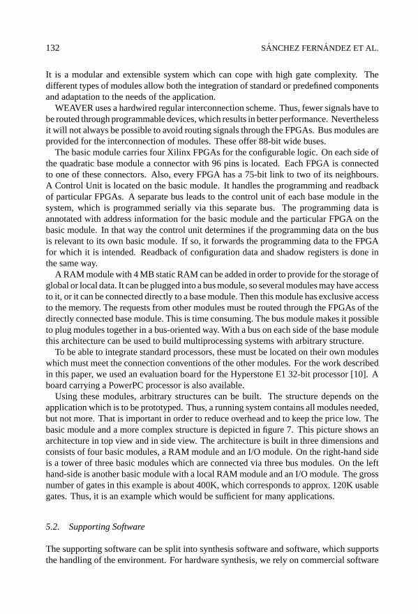
It is a modular and extensible system which can cope with high gate complexity. Thedifferent types of modules allow both the integration of standard or predefined componentsand adaptation to the needs of the application.
WEAVER uses a hardwired regular interconnection scheme. Thus, fewer signals have tobe routed through programmable devices, which results in better performance. Neverthelessit will not always be possible to avoid routing signals through the FPGAs. Bus modules areprovided for the interconnection of modules. These offer 88-bit wide buses.
The basic module carries four Xilinx FPGAs for the configurable logic. On each side ofthe quadratic base module a connector with 96 pins is located. Each FPGA is connectedto one of these connectors. Also, every FPGA has a 75-bit link to two of its neighbours.A Control Unit is located on the basic module. It handles the programming and readbackof particular FPGAs. A separate bus leads to the control unit of each base module in thesystem, which is programmed serially via this separate bus. The programming data isannotated with address information for the basic module and the particular FPGA on thebasic module. In that way the control unit determines if the programming data on the busis relevant to its own basic module. If so, it forwards the programming data to the FPGAfor which it is intended. Readback of configuration data and shadow registers is done inthe same way.
A RAM module with 4 MB static RAM can be added in order to provide for the storage ofglobal or local data. It can be plugged into a bus module, so several modules may have accessto it, or it can be connected directly to a base module. Then this module has exclusive accessto the memory. The requests from other modules must be routed through the FPGAs of thedirectly connected base module. This is time consuming. The bus module makes it possibleto plug modules together in a bus-oriented way. With a bus on each side of the base modulethis architecture can be used to build multiprocessing systems with arbitrary structure.
To be able to integrate standard processors, these must be located on their own moduleswhich must meet the connection conventions of the other modules. For the work describedin this paper, we used an evaluation board for the Hyperstone E1 32-bit processor [10]. Aboard carrying a PowerPC processor is also available.
Using these modules, arbitrary structures can be built. The structure depends on theapplication which is to be prototyped. Thus, a running system contains all modules needed,but not more. That is important in order to reduce overhead and to keep the price low. Thebasic module and a more complex structure is depicted in figure 7. This picture shows anarchitecture in top view and in side view. The architecture is built in three dimensions andconsists of four basic modules, a RAM module and an I/O module. On the right-hand sideis a tower of three basic modules which are connected via three bus modules. On the lefthand-side is another basic module with a local RAM module and an I/O module. The grossnumber of gates in this example is about 400K, which corresponds to approx. 120K usablegates. Thus, it is an example which would be sufficient for many applications.
5.2. Supporting Software
The supporting software can be split into synthesis software and software, which supportsthe handling of the environment. For hardware synthesis, we rely on commercial software

HARDWARE-SOFTWARE PROTOTYPING FROM LOTOS 133
Figure 7. The Weaver hardware.
like Synopsys or any other tool for hardware synthesis, and the Xilinx tool suite. For largecircuits, a netlist partitioning software was developed. This tool allows for the partitioningof a large netlist onto a given device interconnection structure [28].
Software development is done in the particular software development environments pro-vided by the processor vendors. In the case of the Hyperstone processor, software devel-opment is done with PC-based cross development tools including a source level debuggerwhich allows for the debugging of programs running on the target processor.
The WEAVER environment includes a tool which provides a user interface to the ac-cessible functionality: selection of particular boards and FPGAs on the architecture andprogramming, and readback of selected devices. The user has control over the circuit clock,which can be interrupted and chosen from a set of different sources including clock divisors.The user can also set, enable and disable the RESET signal by software means.
6. LOTOS Prototyping
Two kind of inputs are needed in order to construct a prototype: the hardware and softwareLOTOS specifications obtained after the partitioning process (see Section 4.2) and the targetarchitecture (as defined in Section 5). Previous to the construction of the prototype, it isnecessary to build an interface that connects the software and the hardware components. Theresulting code (C and VHDL derived from the LOTOS specifications and also the interfacecode) is then co-simulated in order to test the functionality of the whole system. Finally,the hardware part is mapped onto the FPGA board and the software part to the Hyperstoneboard. Then the whole system is run. At this step some low-level details related to theinterface still have to be debugged. The final result is a working prototype.
As we have already explained in Section 2, a system described using LOTOS communi-cates with its environment by means of events. When translating a LOTOS specification toan implementation language it is necessary to describe how the environment communicateswith the system to perform an event using implementation language primitives, such asfunctions and variables in the case of C or signals in VHDL. From these primitives thehardware-software interface is constructed. Before explaining how the interface is built we
134 SANCHEZ FERNANDEZ ET AL.
describe these primitives. These connect the code generated by TOPO and HARPO withits environment.
6.1. Interfacing Mechanisms of TOPO and HARPO
6.1.1. TOPO. In order to indicate how communications with the environment are to becarried out by the software side of the interface, the designer annotates the LOTOS code.These annotations are in fact user-defined C functions. The annotations are special LOTOScomments that begin with(*| and end with|*). The TOPO tool then converts the annotatedspecification to C. We use four annotations to build the software part of the interface:
• (*| C C statements|*): The annotation keywordC meanscodeand applies to actions.The C statements are executed just after the action is involved in a successful event.
g?b: bool(*| Cprintf ("g");|*) ;
• (*| wait C expression|*): One of the most important annotations is thewait anno-tation. This can be attached to a LOTOS action. During the execution, if the action cantake place, then the expression in thewait annotation is evaluated at each execution stepuntil it returnstrue. Then the action can be performed. Busy wait on await does notpreclude other actions, from occurring.
(*| wait prot in() |*) req !1;
• (*| useC expression|*): This applies to actions of type variable declaration.C expre-ssionvalue is imposed as the value attached to the event. It is equivalent to a valuedeclaration with valueC expression.
get ?d (*| use get input() |*) : nat;
• (∗| priority C expression|∗): ThisC expressionevaluates to a number and expresses thepriority of the action that comes after it. The default priority is 0. The priority can begreater or lower than 0. If nothing else makes a difference, that is, if several events cantake place at a given execution point, priorities affect fairness of the behaviour, forcing aselection. The action with the highest priority is selected. Thus, a positive priority valueimplies a preference, while a negative value labels an undesired event.
6.1.2. HARPO. LOTOS communications imply synchronising, exchanging of data andagreeing on the data among the parties. This scheme can be translated to VHDL by meansof a protocol that has been implemented in the HARPO tool. The protocol is implementedin a library of components.

HARDWARE-SOFTWARE PROTOTYPING FROM LOTOS 135
Figure 8. Implementation of a gate interface in HARPO.
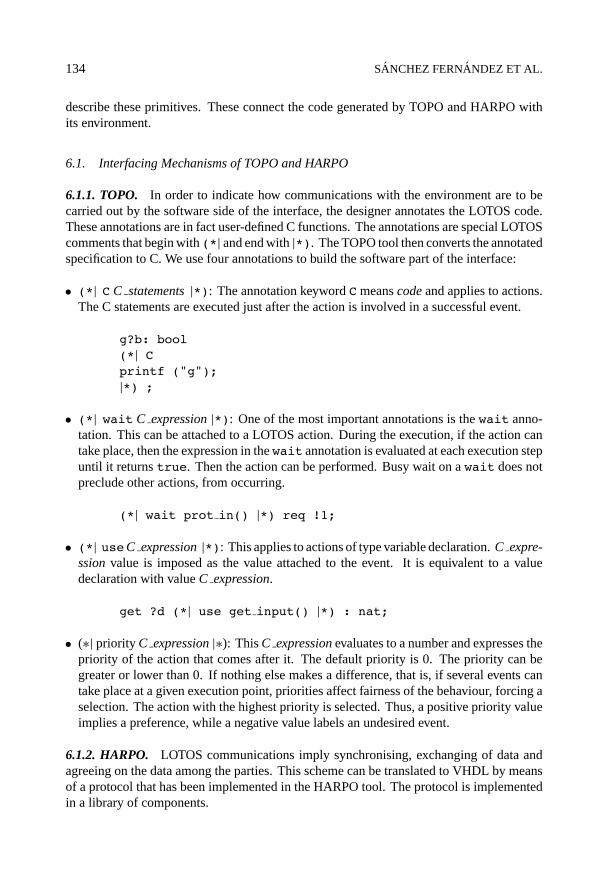
A LOTOS process is translated to a VHDL entity which contains one main process andseveral instantiations (one for each gate) of the library components. The mentioned compo-nents are controlled by the main processes and perform the synchronisations when required.Another benefit is the possibility for parallellising several synchronisations, as different in-stantiations of these components can be triggered in parallel. The components are two:Synch Val for sending andSynch Var for receiving (see figure 8). We use three signalsin VHDL for each LOTOS gate.gate r andgate a are used to perforn the handshakingprotocol andgate is used to carry the data value send from the emitter to the receiver.
The protocol that links the library componentsSynch Val andSynch Var is one of thepossible implementations of the LOTOS synchronisation mechanism between two processeswilling to perform an event on a common gate. Let us study a simple synchronisationbetween two LOTOS processes, one offering a variable and the other offering a value. Forthe interaction to take place, three requirements are necessary:
1. The two processes must be ready to interact, i.e., they wait for each other.2. The value must be of the same sort of the variable.3. Both of them will continue their behaviour after the synchronisation simultaneously.
The second condition is warranted in this approach by imposing on LOTOS gates a givendirection and type.
Let us describe the protocol used by HARPO. There are four stages in order:
1. Synch Val setsgate r to 01 and waits for a01 atgate a.2. Synch Varwaits for a01 atgate r and then it setsgate a to01. This step indicates
that both processes are willing to synchronise on this gate.3. Data is exchanged. When valid data is already atgate, Synch Val setsgate r to00
and waits for a10 or a11 in gate a. Synch Var waits for a00 in gate r and itsetsgate a to 10 if the data is accepted, or to11 otherwise.
4. Processes continue their execution. IfSynch Val received a10 it setsgate r to 10,meaning that the synchronisation has finished successfully; if the value received was11,
136 SANCHEZ FERNANDEZ ET AL.
indicating that some of the receivers did not accept the value, it setsgate r to11, whichimplies that the synchronisation has not occurred and the data is not valid.
Synch Val can setgate r to11 even if it had received a10, and is basically due to theexistence of several possible synchronisations to commit, and the necessity of discardingall but one. It is important to note that following this protocol the writer is the one whodecides finally if a synchronisation takes place or not once the reader has accepted it. Wewill take advantage of this when we build the interface.
6.2. Interface Construction
Currently the interface is still being constructed by hand. Nevertheless, the process couldbe automated, at least for a fixed target architecture. Some guidelines for the constructionof interfaces between hardware and software components which have been obtained fromLOTOS specifications can be found in [23]. In the following we explain the basis ofthe process we have considered, although communication schemes different to the onepresented here could be implemented.
The interface is composed of two parts: one for the software side and one for the hardwareside.
6.2.1. Software Interface. The hardware part of the co-designed system is translated fromLOTOS to VHDL by means of HARPO. The VHDL processes generated communicate witheach other following the handshake protocol we just described. Handshaking also takesplace between the hardware and software parts using the same protocol. Thus, the softwarepart of the interface has to support the protocol. This is achieved through the appropriateuse of thewait annotation. Before each action on a gate in the interface we place awaitannotation.
When a LOTOS process in the software part wants to read a value from the hardwarepart (the LOTOS process in the software part wants to perform an action of kind variabledeclaration) the wait annotation performs the required protocol on its behalf (using the Cfunctionprot in) and returns true if the synchronisation succeeds. These LOTOS actionshave the highest priority, because we need to guarantee that if the wait annotation succeedsthe software will execute that action. If more than one read can occur at a time we usesemaphores (in the example below the semaphore is the C variablein sw smph) to resolvethe potential conflicts:
(*| wait ((in sw smph == 0) && prot in()) |*)(*| priority 1 |*)(* prot in makes the whole protocol, that's why it has
highest priority *)ans? outp (*| use NATdatum(registers map[3][LOW]) |*): nat;(* store value read in outp *)
When a LOTOS process in the software part wants to write a value to the hardware part (theLOTOS process in the software part wants to perform an action of kind value declaration),
HARDWARE-SOFTWARE PROTOTYPING FROM LOTOS 137
the wait annotation performs the protocol by means of the C functionprot out until thepoint where it has to decide if the synchronisation takes place or not, and returns true if thehardware agrees to receive the value on the requested gate. If the execution of the event thentakes place, the protocol finishes successfully with the C functionend prot. After eachstep, all the pending protocols are terminated with failure (remember that the last choicewas on the writer’s side). In this case no priorities or semaphores are needed. Below thereis an example.
(*| wait prot out(0) |*)(* This starts the protocol. If the HW refuses it,
it finishes. If it accepts, it is added to the list ofpending protocols *)
req!Table info(Get source(Get frame(brinf)),Get dest(Get frame(brinf)),Get port(brinf)) (*| C end prot(0); |*);
As this protocol is designed to be independent of the target architecture, so the C func-tions that implement it are also largely architecture-independent. The only part where theinterface is architecture-dependent is where the hardware is directly accessed—that is, theactual reading and writing of data from and to the hardware. This encapsulation makesrelatively easy to port the interface to another target architecture. In Appendix we presentthe C routinesprot in,prot out andend prot.
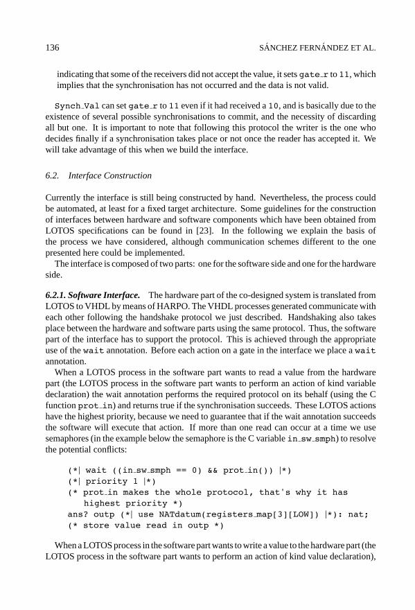
6.2.2. Hardware Interface. The hardware interface is a layer between the VHDL generatedby HARPO and the environment expected by the target architecture. It is in charge of thefollowing tasks:
• Setting the input ports of the LOTOS processes on the hardware side to the values assignedfrom the software side. This may require some registers in which to store the values.• Informing the software about the values held at the output ports of the LOTOS processes
on the hardware side.• Synchronising the read/write operations with the timing imposed by the processor.
In other co-design approaches [9, 26], the interface also includes a handshake protocolwhich passes values between the software and the hardware sides. This is not the case inour approach because, the VHDL generated by HARPO includes that protocol.
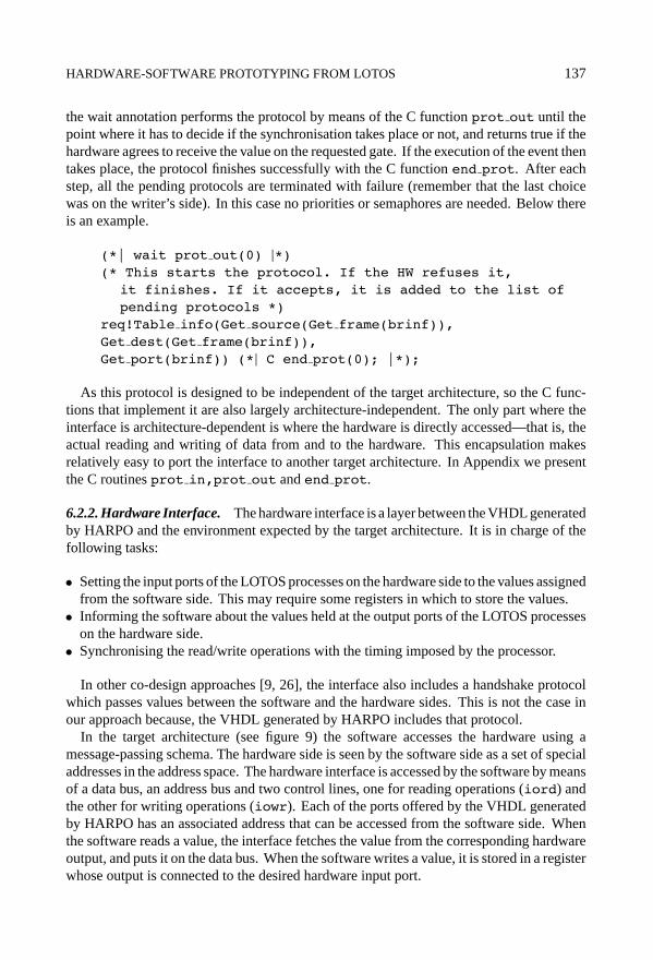
In the target architecture (see figure 9) the software accesses the hardware using amessage-passing schema. The hardware side is seen by the software side as a set of specialaddresses in the address space. The hardware interface is accessed by the software by meansof a data bus, an address bus and two control lines, one for reading operations (iord) andthe other for writing operations (iowr). Each of the ports offered by the VHDL generatedby HARPO has an associated address that can be accessed from the software side. Whenthe software reads a value, the interface fetches the value from the corresponding hardwareoutput, and puts it on the data bus. When the software writes a value, it is stored in a registerwhose output is connected to the desired hardware input port.
138 SANCHEZ FERNANDEZ ET AL.
Figure 9. Interface model.
6.3. Co-Simulation
Once the construction of the interface has been finished, it is necessary to check whetherthe software and hardware parts (together with their interfaces) work correctly together. Todo this we execute the software part and simulate (using a VHDL simulator) the hardwarepart on a SUN workstation. The two parts communicate with each other via files. In thesoftware part the functions that perform reading and writing through the FPGA board arereplaced by functions that read and write into files. In the hardware part we add an extraVHDL component to the interface. It is a wrapper for a set of C functions that performreading and writing operations on files. This strategy allows us to test nearly the same codethat will be implemented on the prototyping board. It allows us to detect at least some ofthe errors that must not appear in the interface construction.
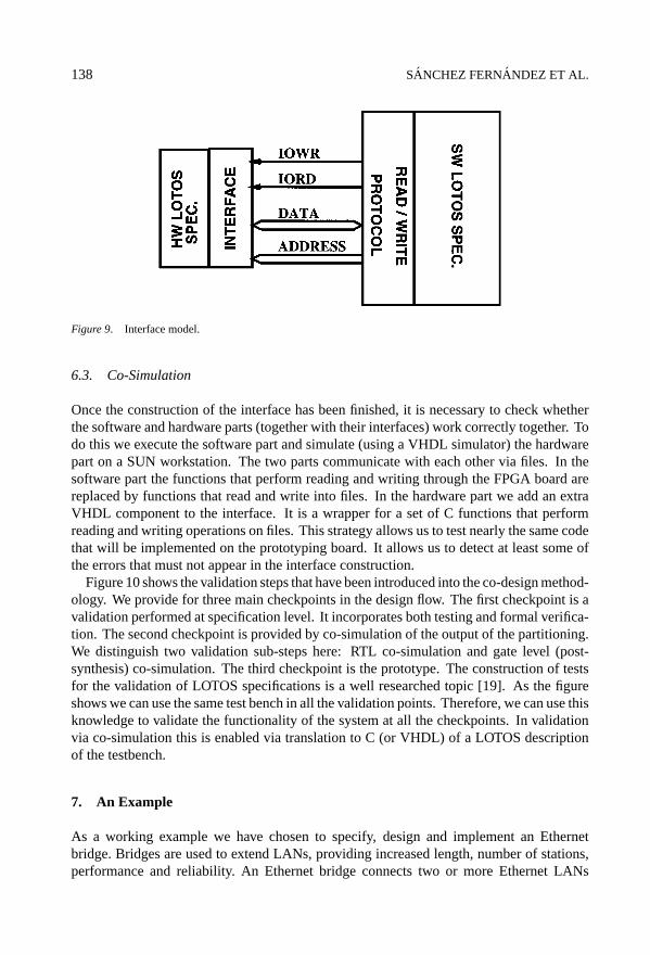
Figure 10 shows the validation steps that have been introduced into the co-design method-ology. We provide for three main checkpoints in the design flow. The first checkpoint is avalidation performed at specification level. It incorporates both testing and formal verifica-tion. The second checkpoint is provided by co-simulation of the output of the partitioning.We distinguish two validation sub-steps here: RTL co-simulation and gate level (post-synthesis) co-simulation. The third checkpoint is the prototype. The construction of testsfor the validation of LOTOS specifications is a well researched topic [19]. As the figureshows we can use the same test bench in all the validation points. Therefore, we can use thisknowledge to validate the functionality of the system at all the checkpoints. In validationvia co-simulation this is enabled via translation to C (or VHDL) of a LOTOS descriptionof the testbench.
7. An Example
As a working example we have chosen to specify, design and implement an Ethernetbridge. Bridges are used to extend LANs, providing increased length, number of stations,performance and reliability. An Ethernet bridge connects two or more Ethernet LANs
HARDWARE-SOFTWARE PROTOTYPING FROM LOTOS 139
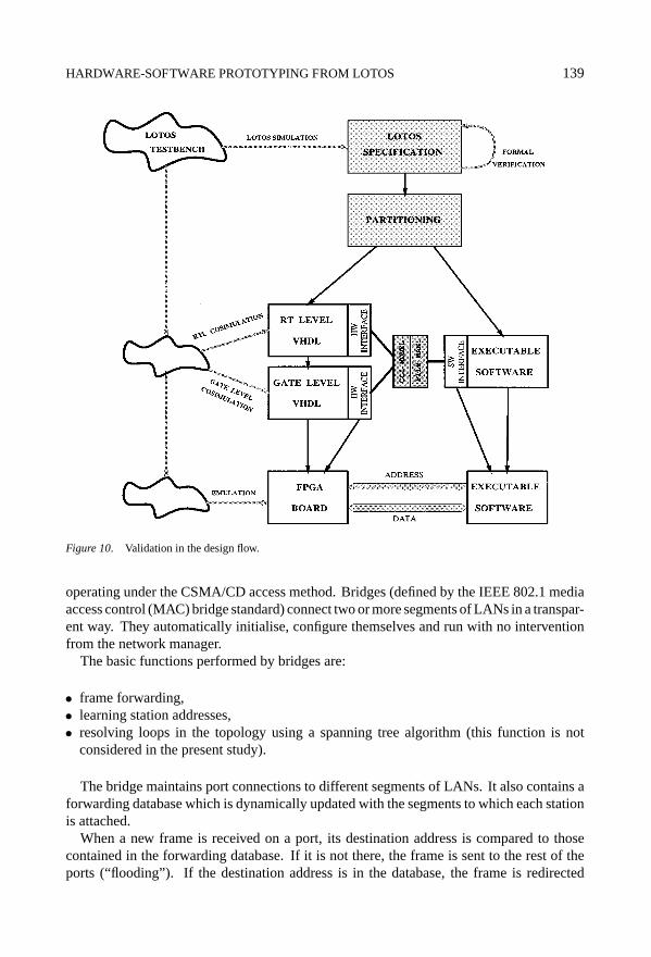
Figure 10. Validation in the design flow.
operating under the CSMA/CD access method. Bridges (defined by the IEEE 802.1 mediaaccess control (MAC) bridge standard) connect two or more segments of LANs in a transpar-ent way. They automatically initialise, configure themselves and run with no interventionfrom the network manager.
The basic functions performed by bridges are:
• frame forwarding,• learning station addresses,• resolving loops in the topology using a spanning tree algorithm (this function is not
considered in the present study).
The bridge maintains port connections to different segments of LANs. It also contains aforwarding database which is dynamically updated with the segments to which each stationis attached.
When a new frame is received on a port, its destination address is compared to thosecontained in the forwarding database. If it is not there, the frame is sent to the rest of theports (“flooding”). If the destination address is in the database, the frame is redirected
140 SANCHEZ FERNANDEZ ET AL.
to the appropriate port, if it is different from the one at which it was received. If bothports are the same, (i.e., the destination is located in the original segment) the frame is notredirected.
The source address is inserted in the database if it was not already present. The identifierof the port and a time-stamp are attached to each address. If the address is already in thedatabase, then the port identifier is updated with the current value, and the time-stamp isrefreshed. Data is removed from the database when the time-stamp indicates that a stationhas been silent for a long time. The removal time, usually a few minutes, is given as aparameter to the specification.
7.1. Specification and Partitioning
Three successive refinements of the initial specification have been completed. The initialspecification handled two Ethernet segments, and defined an algebraic data type for thedatabase and the operations to be performed upon it. The first refinement left the databaseas an algebraic data type and introduced more structure in the ports and control blocks.We designed three port managers, with input and output queues of frames. The secondrefinement addressed the database specification. The functionality of the database wasreallocated to a LOTOS behaviour from a LOTOS data type. The new database behaveslike a hash table.
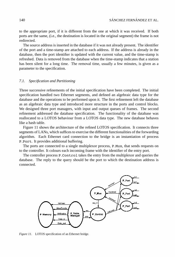
Figure 11 shows the architecture of the refined LOTOS specification. It connects threesegments of LANs, which suffices to exercise the different functionalities of the forwardingalgorithm. Each Ethernet card connection to the bridge is an instantiation of processP Port. It provides additional buffering.
The ports are connected to a single multiplexor process,P Mux, that sends requests onto the controller. It colours each incoming frame with the identifier of the entry port.
The controller processP Control takes the entry from the multiplexor and queries thedatabase. The reply to the query should be the port to which the destination address isconnected.
Figure 11. LOTOS specification of an Ethernet bridge.
HARDWARE-SOFTWARE PROTOTYPING FROM LOTOS 141
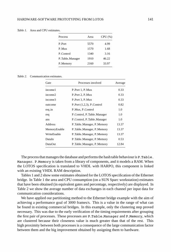
Table 1. Area and CPU estimates.
Process Area CPU (%)
P Port 5570 4.99
P Mux 1570 1.68
P Control 1340 3.16
P TableManager 1910 46.22
P Memory 2160 33.97
Table 2. Communication estimates.
Gate Processes involved Average
income1 PPort 1, PMux 0.33
income2 PPort 2, PMux 0.33
income3 PPort 3, PMux 0.33
outcome PPort (1,2,3), PControl 0.82
req in P Mux, P Control 1.0
req PControl, PTableManager 1.0
ans PControl, PTableManager 1.0
Address PTableManager, PMemory 13.37
MemoryEnable PTableManager, PMemory 13.37
WriteEnable PTableManager, PMemory 13.37
DataIn PTableManager, PMemory 0.53
DataOut PTableManager, PMemory 12.84
The process that manages the database and performs the hash table behaviour isP TableManager. P Memory is taken from a library of components, and it models a RAM. Whenthe LOTOS specification is translated to VHDL with HARPO, this component is linkedwith an existing VHDL RAM description.
Tables 1 and 2 show some estimates obtained for the LOTOS specification of the Ethernetbridge. In Table 1 the area and CPU consumption (on a SUN Sparc workstation) estimatesthat have been obtained (in equivalent gates and percentage, respectively) are displayed. InTable 2 we show the average number of data exchanges in each channel per input data forcommunication considerations.
We have applied our partitioning method to the Ethernet bridge example with the aim ofachieving a performance goal of 3000 frames/s. This is a value in the range of what canbe found in existing commercial bridges. In this example, only the clustering step provednecessary. This was due to the early verification of the timing requirements after groupingthe first pair of processes. These processes areP Table Manager andP Memory, whichare clustered because their closeness value is much greater than that of the rest. Thishigh proximity between both processes is a consequence of the large communication factorbetween them and the big improvement obtained by assigning them to hardware.
142 SANCHEZ FERNANDEZ ET AL.
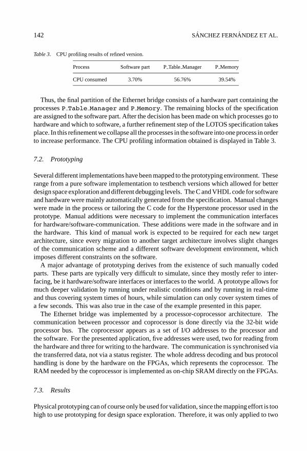
Table 3. CPU profiling results of refined version.
Process Software part PTableManager PMemory
CPU consumed 3.70% 56.76% 39.54%
Thus, the final partition of the Ethernet bridge consists of a hardware part containing theprocessesP Table Manager andP Memory. The remaining blocks of the specificationare assigned to the software part. After the decision has been made on which processes go tohardware and which to software, a further refinement step of the LOTOS specification takesplace. In this refinement we collapse all the processes in the software into one process in orderto increase performance. The CPU profiling information obtained is displayed in Table 3.
7.2. Prototyping
Several different implementations have been mapped to the prototyping environment. Theserange from a pure software implementation to testbench versions which allowed for betterdesign space exploration and different debugging levels. The C and VHDL code for softwareand hardware were mainly automatically generated from the specification. Manual changeswere made in the process or tailoring the C code for the Hyperstone processor used in theprototype. Manual additions were necessary to implement the communication interfacesfor hardware/software-communication. These additions were made in the software and inthe hardware. This kind of manual work is expected to be required for each new targetarchitecture, since every migration to another target architecture involves slight changesof the communication scheme and a different software development environment, whichimposes different constraints on the software.
A major advantage of prototyping derives from the existence of such manually codedparts. These parts are typically very difficult to simulate, since they mostly refer to inter-facing, be it hardware/software interfaces or interfaces to the world. A prototype allows formuch deeper validation by running under realistic conditions and by running in real-timeand thus covering system times of hours, while simulation can only cover system times ofa few seconds. This was also true in the case of the example presented in this paper.
The Ethernet bridge was implemented by a processor-coprocessor architecture. Thecommunication between processor and coprocessor is done directly via the 32-bit wideprocessor bus. The coprocessor appears as a set of I/O addresses to the processor andthe software. For the presented application, five addresses were used, two for reading fromthe hardware and three for writing to the hardware. The communication is synchronised viathe transferred data, not via a status register. The whole address decoding and bus protocolhandling is done by the hardware on the FPGAs, which represents the coprocessor. TheRAM needed by the coprocessor is implemented as on-chip SRAM directly on the FPGAs.
7.3. Results
Physical prototyping can of course only be used for validation, since the mapping effort is toohigh to use prototyping for design space exploration. Therefore, it was only applied to two
HARDWARE-SOFTWARE PROTOTYPING FROM LOTOS 143
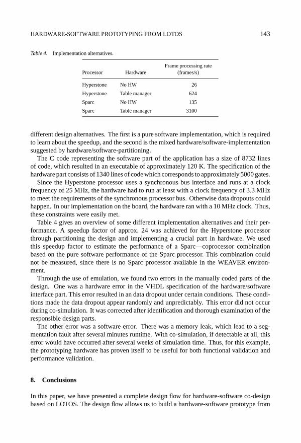
Table 4. Implementation alternatives.
Frame processing rateProcessor Hardware (frames/s)
Hyperstone No HW 26
Hyperstone Table manager 624
Sparc No HW 135
Sparc Table manager 3100
different design alternatives. The first is a pure software implementation, which is requiredto learn about the speedup, and the second is the mixed hardware/software-implementationsuggested by hardware/software-partitioning.
The C code representing the software part of the application has a size of 8732 linesof code, which resulted in an executable of approximately 120 K. The specification of thehardware part consists of 1340 lines of code which corresponds to approximately 5000 gates.
Since the Hyperstone processor uses a synchronous bus interface and runs at a clockfrequency of 25 MHz, the hardware had to run at least with a clock frequency of 3.3 MHzto meet the requirements of the synchronous processor bus. Otherwise data dropouts couldhappen. In our implementation on the board, the hardware ran with a 10 MHz clock. Thus,these constraints were easily met.
Table 4 gives an overview of some different implementation alternatives and their per-formance. A speedup factor of approx. 24 was achieved for the Hyperstone processorthrough partitioning the design and implementing a crucial part in hardware. We usedthis speedup factor to estimate the performance of a Sparc—coprocessor combinationbased on the pure software performance of the Sparc processor. This combination couldnot be measured, since there is no Sparc processor available in the WEAVER environ-ment.
Through the use of emulation, we found two errors in the manually coded parts of thedesign. One was a hardware error in the VHDL specification of the hardware/softwareinterface part. This error resulted in an data dropout under certain conditions. These condi-tions made the data dropout appear randomly and unpredictably. This error did not occurduring co-simulation. It was corrected after identification and thorough examination of theresponsible design parts.
The other error was a software error. There was a memory leak, which lead to a seg-mentation fault after several minutes runtime. With co-simulation, if detectable at all, thiserror would have occurred after several weeks of simulation time. Thus, for this example,the prototyping hardware has proven itself to be useful for both functional validation andperformance validation.
8. Conclusions
In this paper, we have presented a complete design flow for hardware-software co-designbased on LOTOS. The design flow allows us to build a hardware-software prototype from

144 SANCHEZ FERNANDEZ ET AL.
an initial abstract specification written in LOTOS. A worked example, the Ethernet bridgeserved to illustrate the proposed design flow. The speedup and performance results that wehave presented prove the feasibility of the proposed approach.
Our design flow is composed of three different phases corresponding to three abstractionlevels (high-level specification, hardware and software specification, prototyping). Thedesign flow is validated at the high-level specification level (by means of simulation andformal verification) and at the prototype level (by means of cosimulation and by running theobtained prototype on the prototype board). The techniques used at high-level specification(abstract specification, formal verification and refinement, testing) and at the prototypelevel (co-simulation and hardware-software prototyping from VHDL and C code obtainedfrom the specification and the interface) are not new. Our aim was to develop a coherentpath from this high-level specification formalisms to prototyping. This makes it possibleto apply the features available in high-level specification languages for the development ofreal designs.
Appendix
Functions Used in the Ethernet Bridge Interface
We present here the C code used in the implementation of the Ethernet bridge interface,together with a short explanation of how the functions work.
We use two variables calledregisters map andin reg to store the values that areread and written in the hardware part. For the data carried through gatereq we need threeelements ofregisters map (req1, req2 andreq3).
/* registers map[0][HIGH] = req r *//* registers map[0][LOW] = ans a *//* registers map[1][HIGH] = req1 *//* registers map[1][LOW] = req2 *//* registers map[2][HIGH] = req3 *//* registers map[2][LOW] = --- *//* registers map[3][HIGH] = --- *//* registers map[3][LOW] = ans *//* in reg[HIGH] -- req a *//* in reg[LOW] -- ans r */
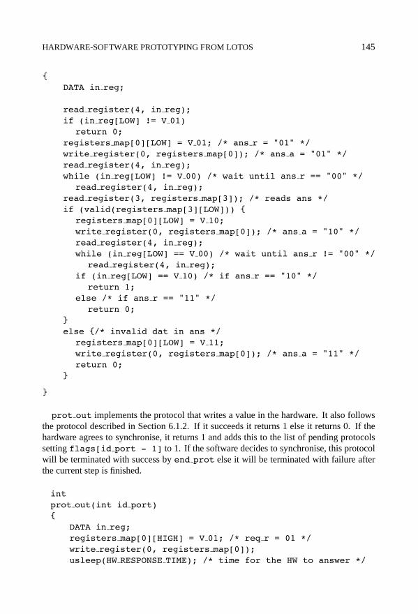
prot in implements the protocol that reads a value from the hardware. It followsthe protocol described in Section 6.1.2. If it succeeds it returns 1 else it returns 0. Thefunctionswrite register andread register are used to write to and read data fromthe hardware. The functionvalid decides if the value offered by the hardware is to beaccepted.
intprot in()
HARDWARE-SOFTWARE PROTOTYPING FROM LOTOS 145
{DATA in reg;
read register(4, in reg);if (in reg[LOW] != V 01)
return 0;registers map[0][LOW] = V 01; /* ans r = "01" */write register(0, registers map[0]); /* ans a = "01" */read register(4, in reg);while (in reg[LOW] != V 00) /* wait until ans r == "00" */
read register(4, in reg);read register(3, registers map[3]); /* reads ans */if (valid(registers map[3][LOW])) {
registers map[0][LOW] = V 10;write register(0, registers map[0]); /* ans a = "10" */read register(4, in reg);while (in reg[LOW] == V 00) /* wait until ans r != "00" */
read register(4, in reg);if (in reg[LOW] == V 10) /* if ans r == "10" */
return 1;else /* if ans r == "11" */
return 0;}else {/* invalid dat in ans */
registers map[0][LOW] = V 11;write register(0, registers map[0]); /* ans a = "11" */return 0;
}
}
prot out implements the protocol that writes a value in the hardware. It also followsthe protocol described in Section 6.1.2. If it succeeds it returns 1 else it returns 0. If thehardware agrees to synchronise, it returns 1 and adds this to the list of pending protocolssettingflags[id port - 1] to 1. If the software decides to synchronise, this protocolwill be terminated with success byend prot else it will be terminated with failure afterthe current step is finished.
intprot out(int id port){
DATA in reg;registers map[0][HIGH] = V 01; /* req r = 01 */write register(0, registers map[0]);usleep(HW RESPONSE TIME); /* time for the HW to answer */

146 SANCHEZ FERNANDEZ ET AL.
read register(4, in reg);if (in reg[HIGH] == V 01) {/* req a = "01" */
write register(1, registers map[1]);/* send req1,req2,req3 */
write register(2, registers map[2]);registers map[0][HIGH] = V 00; /* req r = 00 */write register(0, registers map[0]);read register(4, in reg);while ((in reg[HIGH] != V 10) && (in reg[HIGH] != V 11))read register(4, in reg); /* req a= 10 or req a=11 */
if (in reg[HIGH] == V 11) {registers map[0][HIGH] = V 11; /* req r = 11 */write register(0, registers map[0]);return 0;
}if (in reg[HIGH] == V 10) {flags[id port - 1] = 1;return 1;
}}return 0;
}
Finally,end prot completes a writing protocol that has succeeded.
voidend prot(int id port){
registers map[0][HIGH] = V 10; /* req r = 10 */write register(0, registers map[0]);flags[id port - 1] = 0;
}
Acknowledgments
We would like to thank Juan Carlos L´opez Lopez and Carlos Carreras Vaquer for theirfruitful collaboration in the development of the LOTOS design flow during the COBRAproject. We would also want to thank the teams that developed the translators from LOTOSto C and VHDL for their support, especially Andr´es Mar´ın Lopez. Helpful comments andsuggestions made by Peter T. Breuer are gratefully acknowledged.
This work has been partially funded by ESPRIT project No. 8135 COBRA and CICYTproject TIC94-0627-CE.
HARDWARE-SOFTWARE PROTOTYPING FROM LOTOS 147
References
1. E. Barros, W. Rosenstiel, and X. Xiong, “Hardware/software partitioning with UNITY,”2nd InternationalWorkshop on Hardware-Software Co-Design, Cambridge, MA, October 1993.
2. J. Berge, O. Levia, and J. Rouillard, eds.,High-Level System Modeling: Specification Languages. CurrentIssues in Electronic Modeling, Vol. 3, Kluwer Academic Publishers, September 1995.
3. C. Carreras, J.C. L´opez, M.L. Lopez, C. Delgado-Kloos, N. Mart´ınez, and L. S´anchez, “A co-design method-ology based on formal specification and high-level estimation,”4th International Workshop on Hardware-Software Co-Design, Pittsburgh, IEEE Computer Society Press, March 1996.
4. M. Chiodo, P. Giusto, H. Hsieh, A. Jurecska, L. Lavagno, and A. Sangiovanni-Vincentelli, “Hardware-softwarecodesign of embedded systems,”IEEE Micro, 14(4): 26–36, August 1994.
5. R.A. Cottrell, “ASIC design using silicon 1076,” inVHDL for Simulation, Synthesis and Formal Proofs ofHardware, J. Mermet, ed., Kluwer Academic Publishers, 1992.
6. C. Delgado Kloos, A. Mar´ın Lopez, T. de Miguel Moro, and T. Robles Valladares, “From LOTOS to VHDL,”in High-Level System Modeling: Specification Languages. Current Issues in Electronic Modeling, J. Berge,O. Levia, and J. Rouillard, eds., Vol. 3, Kluwer Academic Publishers, September 1995.
7. R. Ernst, J. Henkel, and T. Benner, “Hardware-software cosynthesis for microcontrollers,”IEEE Design &Test of Computers, pp. 64–75, December 1993.
8. D. Gajski, F. Vahid, S. Narayan, and J. Gong,Specification and Design of Embedded Systems, Prentice Hall,New Jersey, 1994.
9. R. Gupta and G. DeMicheli, “Hardware-software cosynthesis for digital systems,”IEEE Design & Test ofComputers, pp. 29–41, September 1993.
10. Hyperstone Electronics,Hyperstone E1 32-Bit-Microprocessor User’s Manual, 1990.11. Information Processing Systems—Open Systems Interconnection—LOTOS: A Formal Description Technique
Based on the Temporal Ordering of Observational Behaviour, IS-8807, International Standards Organization,1989.
12. T. Ismail and A. Jerraya, “Synthesis steps and design models for co-design,”IEEE Computer, 28(2): 44–52,February 1995.
13. S.C. Johnson, “Hierarchical clustering schemes,”Psychometrika, 32: 241–254, September 1967.14. B.W. Kernighan and S. Lin, “An efficient heuristic procedure for partitioning graphs,”Bell Syst. Tech. J., 4(2):
291–308, 1970.15. G. Koch, U. Kebschull, and W. Rosenstiel, “A prototyping architecture for hardware/software codesign
in the COBRA project,” inProceedings of 3rd international Workshop on Hardware/Software CodesignCodes/CASHE’94, Grenoble, 1994.
16. M.L. Lopez Vallejo et al., “Coarse grain partitioning for hardware-software co-design,”22nd EuromicroConference, EUROMICRO’96, Prague, September 1996.
17. J.A. Manas and T. de Miguel, “From LOTOS to C,” inFormal Description Techniques, I, K.J. Turner, ed.,pp. 79–84, Stirling, Scotland, UK, 1989. IFIP, North-Holland.Proceedings FORTE’88, September 1988.
18. C. Miguel, A. Fern´andez, J.M. Ortuno, and L. Vidaller, “A LOTOS based performance evaluation tool,”special issue ofComputer Networks and ISDN Systems, in Tools for FDTs, 25(7): 791–813, February 1993.
19. J. Quemada, A. Azcorra, and S. Pav´on, “Development with LOTOS,” inUsing Formal Description Techniques,K.J. Turner, ed., John Wiley and Sons, Chichester, UK, 1993, pp. 345–373.
20. J. Quemada, S. Pav´on, and A. Fern´andez, “State exploration by transformation with LOLA,”Workshop onAutomatic Verification Methods for Finite State Systems, Grenoble, June 1989.
21. L. Sanchez Fern´andez, “Contribuci´on a la especificaci´on de aspectos no funcionales de sistemas hardware-software,” Ph.D. Thesis, Technical University of Madrid, July 1997.
22. L. Sanchez Fern´andez, N. Mart´ınez Madrid, and C. Delgado Kloos, “Integrating non-functional aspects intoLOTOS,” Current Issues in Electronic Modeling, Vol. 4, Kluwer Academic Publishers, December 1995.
23. L. Sanchez Fern´andez, N. Mart´ınez Madrid, and C. Delgado Kloos, “LOTOS-based system co-design,”Technical Report of the ESPRIT COBRA (EP 8135) project, Madrid, April 1996.
24. K. Stølen and M. Fuchs, “A formal method for hardware/software co-design,” Technical Report, Institut f¨urInformatik, Technische Universit¨at Munchen, May 1995.

148 SANCHEZ FERNANDEZ ET AL.
25. K.J. Turner, ed.,Using Formal Description Techniques, John Wiley and Sons, Chichester, UK, 1993.26. S. Vercauteren and B. Lin, “Hardware/software communication and system integration for embedded archi-
tectures,”Design Automation for Embedded Systems, 2(3/4): 359–382, May 1997.27. C. Weiler, U. Kebschull, and W. Rosenstiel, “C++ base classes for specification, simulation and partitioning
of a hardware/software system,” inProceedings of VLSI’95, pp. 777–784, 1995.28. U. Weinmann, “FPGA partitioning under timing constraints,”Int. Workshop on Field Programmable Logic
and Applications, Oxford, September 1993.