Embed Size (px)
Citation preview
Hardware Reference GuideHP Compaq Business PC
dc7600 Small Form Factor Model
Document Part Number: 384571-001
May 2005
This guide provides basic information for upgrading this computer model.
© Copyright 2005 Hewlett-Packard Development Company, L.P.The information contained herein is subject to change without notice.
Microsoft and Windows are trademarks of Microsoft Corporation in the U.S. and other countries.
The only warranties for HP products and services are set forth in the express warranty statements accompanying such products and services. Nothing herein should be construed as constituting an additional warranty. HP shall not be liable for technical or editorial errors or omissions contained herein.
This document contains proprietary information that is protected by copyright. No part of this document may be photocopied, reproduced, or translated to another language without the prior written consent of Hewlett-Packard Company.
ÅWARNING: Text set off in this manner indicates that failure to follow directions could result in bodily harm or loss of life.
ÄCAUTION: Text set off in this manner indicates that failure to follow directions could result in damage to equipment or loss of information.
Hardware Reference GuideHP Compaq Business PC
dc7600 Small Form Factor Model
First Edition (May 2005)
Document Part Number: 384571-001
Contents
1 Product Features
Standard Configuration Features. . . . . . . . . . . . . . . . . . . . . . . . . . . . . . . . . . . . . . . . . . 1–1Front Panel Components . . . . . . . . . . . . . . . . . . . . . . . . . . . . . . . . . . . . . . . . . . . . . . . . 1–2Rear Panel Components . . . . . . . . . . . . . . . . . . . . . . . . . . . . . . . . . . . . . . . . . . . . . . . . 1–3Keyboard . . . . . . . . . . . . . . . . . . . . . . . . . . . . . . . . . . . . . . . . . . . . . . . . . . . . . . . . . . . . 1–4
Windows Logo Key . . . . . . . . . . . . . . . . . . . . . . . . . . . . . . . . . . . . . . . . . . . . . . . . 1–5Special Mouse Functions. . . . . . . . . . . . . . . . . . . . . . . . . . . . . . . . . . . . . . . . . . . . . . . . 1–5Serial Number Location . . . . . . . . . . . . . . . . . . . . . . . . . . . . . . . . . . . . . . . . . . . . . . . . 1–6
2 Hardware Upgrades
Serviceability Features . . . . . . . . . . . . . . . . . . . . . . . . . . . . . . . . . . . . . . . . . . . . . . . . . 2–1Warnings and Cautions . . . . . . . . . . . . . . . . . . . . . . . . . . . . . . . . . . . . . . . . . . . . . . . . . 2–1Using the Small Form Factor Computer in a Tower Orientation . . . . . . . . . . . . . . . . . 2–2Unlocking the Smart Cover Lock . . . . . . . . . . . . . . . . . . . . . . . . . . . . . . . . . . . . . . . . . 2–3
Using the Smart Cover FailSafe Key . . . . . . . . . . . . . . . . . . . . . . . . . . . . . . . . . . . 2–3Removing the Computer Cover. . . . . . . . . . . . . . . . . . . . . . . . . . . . . . . . . . . . . . . . . . . 2–5Replacing the Computer Cover . . . . . . . . . . . . . . . . . . . . . . . . . . . . . . . . . . . . . . . . . . . 2–6Installing Additional Memory . . . . . . . . . . . . . . . . . . . . . . . . . . . . . . . . . . . . . . . . . . . . 2–7
DIMMs . . . . . . . . . . . . . . . . . . . . . . . . . . . . . . . . . . . . . . . . . . . . . . . . . . . . . . . . . . 2–7DDR2-SDRAM DIMMs. . . . . . . . . . . . . . . . . . . . . . . . . . . . . . . . . . . . . . . . . . . . . 2–7Populating DIMM Sockets . . . . . . . . . . . . . . . . . . . . . . . . . . . . . . . . . . . . . . . . . . . 2–8Installing DIMMs . . . . . . . . . . . . . . . . . . . . . . . . . . . . . . . . . . . . . . . . . . . . . . . . . 2–10
Installing an Expansion Card . . . . . . . . . . . . . . . . . . . . . . . . . . . . . . . . . . . . . . . . . . . 2–13Removing a PCI Express x16 Expansion Card . . . . . . . . . . . . . . . . . . . . . . . . . . . . . . 2–17Installing Additional Drives . . . . . . . . . . . . . . . . . . . . . . . . . . . . . . . . . . . . . . . . . . . . 2–19
Locating Drive Positions . . . . . . . . . . . . . . . . . . . . . . . . . . . . . . . . . . . . . . . . . . . 2–20Removing an Optical Drive . . . . . . . . . . . . . . . . . . . . . . . . . . . . . . . . . . . . . . . . . 2–21Removing a Diskette Drive. . . . . . . . . . . . . . . . . . . . . . . . . . . . . . . . . . . . . . . . . . 2–25Installing an Optional Optical Drive. . . . . . . . . . . . . . . . . . . . . . . . . . . . . . . . . . . 2–28
Hardware Reference Guide www.hp.com iii
Contents
Upgrading the SATA Hard Drive. . . . . . . . . . . . . . . . . . . . . . . . . . . . . . . . . . . . . 2–33Installing an Optional Drive into the 3.5-inch Drive Bay. . . . . . . . . . . . . . . . . . . 2–39
A Specifications
B Battery Replacement
C Security Lock Provisions
Installing a Security Lock . . . . . . . . . . . . . . . . . . . . . . . . . . . . . . . . . . . . . . . . . . . . . . . C–1Cable Lock . . . . . . . . . . . . . . . . . . . . . . . . . . . . . . . . . . . . . . . . . . . . . . . . . . . . . . . C–1Padlock . . . . . . . . . . . . . . . . . . . . . . . . . . . . . . . . . . . . . . . . . . . . . . . . . . . . . . . . . . C–2Universal Chassis Clamp Lock. . . . . . . . . . . . . . . . . . . . . . . . . . . . . . . . . . . . . . . . C–3
D Electrostatic Discharge
Preventing Electrostatic Damage . . . . . . . . . . . . . . . . . . . . . . . . . . . . . . . . . . . . . . . . . D–1Grounding Methods. . . . . . . . . . . . . . . . . . . . . . . . . . . . . . . . . . . . . . . . . . . . . . . . . . . . D–1
E Computer Operating Guidelines, Routine Care and Shipping Preparation
Computer Operating Guidelines and Routine Care. . . . . . . . . . . . . . . . . . . . . . . . . . . . E–1Optical Drive Precautions . . . . . . . . . . . . . . . . . . . . . . . . . . . . . . . . . . . . . . . . . . . . . . . E–2
Operation . . . . . . . . . . . . . . . . . . . . . . . . . . . . . . . . . . . . . . . . . . . . . . . . . . . . . . . . E–2Cleaning . . . . . . . . . . . . . . . . . . . . . . . . . . . . . . . . . . . . . . . . . . . . . . . . . . . . . . . . . E–2Safety . . . . . . . . . . . . . . . . . . . . . . . . . . . . . . . . . . . . . . . . . . . . . . . . . . . . . . . . . . . E–2
Shipping Preparation . . . . . . . . . . . . . . . . . . . . . . . . . . . . . . . . . . . . . . . . . . . . . . . . . . . E–3
Index
iv www.hp.com Hardware Reference Guide
1Product Features
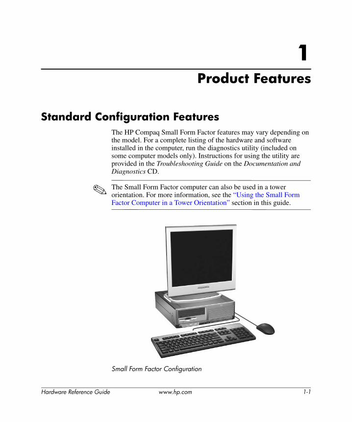
Standard Configuration FeaturesThe HP Compaq Small Form Factor features may vary depending on the model. For a complete listing of the hardware and software installed in the computer, run the diagnostics utility (included on some computer models only). Instructions for using the utility are provided in the Troubleshooting Guide on the Documentation and Diagnostics CD.
✎ The Small Form Factor computer can also be used in a tower orientation. For more information, see the “Using the Small Form Factor Computer in a Tower Orientation” section in this guide.
Small Form Factor Configuration
Hardware Reference Guide www.hp.com 1-1

Product Features
Front Panel ComponentsDrive configuration may vary by model.
Front Panel Components
1 Diskette Drive Activity Light 7 Microphone Connector
2 Diskette Drive 8 Headphone Connector
3 Optical Drive Activity Light 9 USB (Universal Serial Bus) Ports (2)
4 Diskette Eject Button - Hard Drive Activity Light
5 Optical Drive (CD-ROM, CD-R/RW, DVD-ROM, DVD+R/RW, or CD-RW/DVD Combo Drive)
q Power On Light
6 Optical Drive Eject Button w Dual-State Power Button
✎ Some models do not include an optical or diskette drive.
1-2 www.hp.com Hardware Reference Guide
Product Features
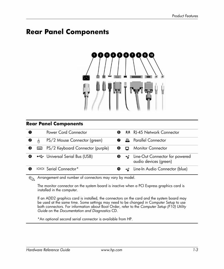
Rear Panel Components
Rear Panel Components
1 Power Cord Connector 6 n RJ-45 Network Connector
2 b PS/2 Mouse Connector (green) 7 l Parallel Connector
3 a PS/2 Keyboard Connector (purple) 8 c Monitor Connector
4 o Universal Serial Bus (USB) 9 k Line-Out Connector for powered audio devices (green)
5 m Serial Connector* - j Line-In Audio Connector (blue)
✎ Arrangement and number of connectors may vary by model.
The monitor connector on the system board is inactive when a PCI Express graphics card is installed in the computer.
If an ADD2 graphics card is installed, the connectors on the card and the system board may be used at the same time. Some settings may need to be changed in Computer Setup to use both connectors. For information about Boot Order, refer to the Computer Setup (F10) Utility Guide on the Documentation and Diagnostics CD.
*An optional second serial connector is available from HP.
Hardware Reference Guide www.hp.com 1-3
Product Features
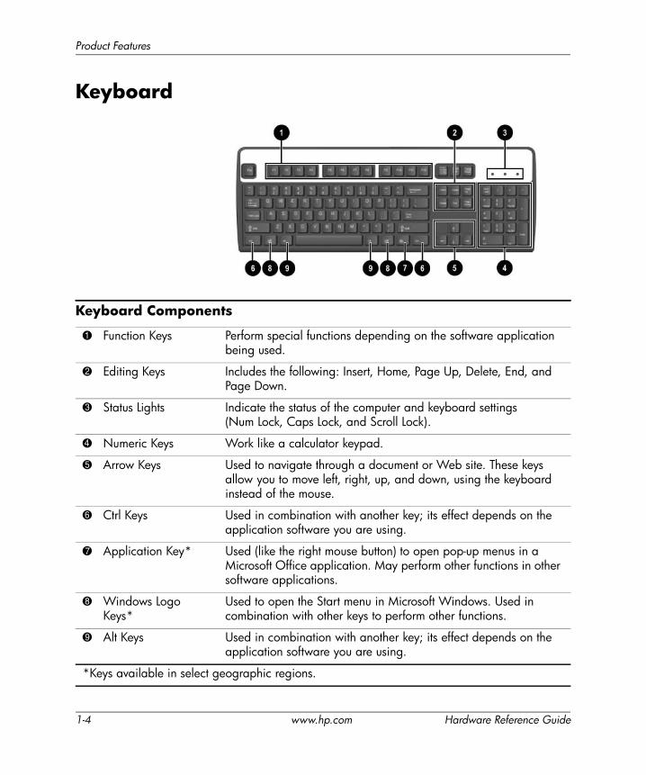
Keyboard
Keyboard Components
1 Function Keys Perform special functions depending on the software application being used.
2 Editing Keys Includes the following: Insert, Home, Page Up, Delete, End, and Page Down.
3 Status Lights Indicate the status of the computer and keyboard settings (Num Lock, Caps Lock, and Scroll Lock).
4 Numeric Keys Work like a calculator keypad.
5 Arrow Keys Used to navigate through a document or Web site. These keys allow you to move left, right, up, and down, using the keyboard instead of the mouse.
6 Ctrl Keys Used in combination with another key; its effect depends on the application software you are using.
7 Application Key* Used (like the right mouse button) to open pop-up menus in a Microsoft Office application. May perform other functions in other software applications.
8 Windows Logo Keys*
Used to open the Start menu in Microsoft Windows. Used in combination with other keys to perform other functions.
9 Alt Keys Used in combination with another key; its effect depends on the application software you are using.
*Keys available in select geographic regions.
1-4 www.hp.com Hardware Reference Guide
Product Features
Windows Logo KeyUse the Windows Logo key in combination with other keys to perform certain functions available in the Windows operating system. Refer to the “Keyboard” section to identify the Windows Logo key.
Special Mouse FunctionsMost software applications support the use of a mouse. The functions assigned to each mouse button depend on the software applications you are using.
Windows Logo Key Functions
Windows Logo Key Displays or hides the Start menu.
Windows Logo Key + d Displays the Desktop.
Windows Logo Key + m Minimizes all open applications.
Shift + Windows Logo Key + m Undoes Minimize All.
Windows Logo Key + e Launches My Computer.
Windows Logo Key + f Launches Find Document.
Windows Logo Key + Ctrl + f Launches Find Computer.
Windows Logo Key + F1 Launches Windows Help.
Windows Logo Key + l Locks the computer if you are connected to a network domain, or allows you to switch users if you are not connected to a network domain.
Windows Logo Key + r Launches the Run dialog box.
Windows Logo Key + u Launches the Utility Manager.
Windows Logo Key + Tab Activates the next Taskbar button.
Hardware Reference Guide www.hp.com 1-5
Product Features
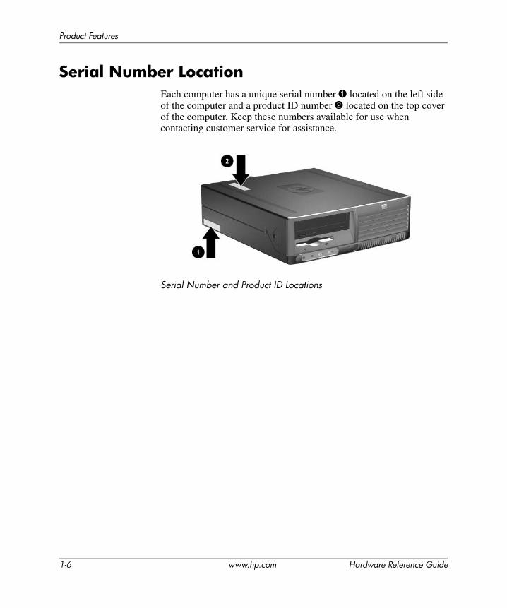
Serial Number LocationEach computer has a unique serial number 1 located on the left side of the computer and a product ID number 2 located on the top cover of the computer. Keep these numbers available for use when contacting customer service for assistance.
Serial Number and Product ID Locations
1-6 www.hp.com Hardware Reference Guide
2Hardware Upgrades
Serviceability FeaturesThis computer includes features that make it easy to upgrade and service. No tools are needed for most of the installation procedures described in this chapter.
Warnings and CautionsBefore performing upgrades be sure to carefully read all of the applicable instructions, cautions, and warnings in this guide.
ÅWARNING: To reduce the risk of personal injury from electrical shock and/or hot surfaces, be sure to disconnect the power cord from the wall outlet, and allow the internal system components to cool before touching.
ÅWARNING: To reduce the risk of electrical shock, fire, or damage to the equipment, do not plug telecommunications/telephone connectors into the network interface controller (NIC) receptacles.
ÄCAUTION: Static electricity can damage the electronic components of the computer or optional equipment. Before beginning these procedures, ensure that you are discharged of static electricity by briefly touching a grounded metal object. Refer to Appendix D, “Electrostatic Discharge” in this guide for additional information on preventing electrostatic discharge.
ÄCAUTION: When the computer is plugged into an AC power source, voltage is always applied to the system board. You must disconnect the power cord from the power source before opening the computer to prevent system board damage.
Hardware Reference Guide www.hp.com 2-1
Hardware Upgrades
Using the Small Form Factor Computer in a Tower Orientation
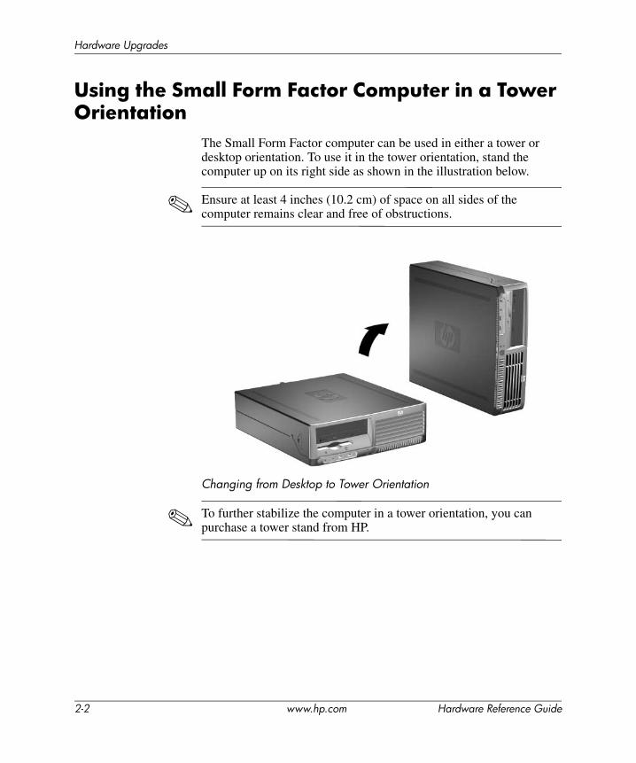
The Small Form Factor computer can be used in either a tower or desktop orientation. To use it in the tower orientation, stand the computer up on its right side as shown in the illustration below.
✎ Ensure at least 4 inches (10.2 cm) of space on all sides of the computer remains clear and free of obstructions.
Changing from Desktop to Tower Orientation
✎ To further stabilize the computer in a tower orientation, you can purchase a tower stand from HP.
2-2 www.hp.com Hardware Reference Guide
Hardware Upgrades
Unlocking the Smart Cover Lock
✎ The Smart Cover Lock is an optional feature and is available on some models only.
The Smart Cover Lock is a software-controllable cover lock, controlled by the setup password. This lock prevents unauthorized access to the internal components. The computer ships with the Smart Cover Lock in the unlocked position. For more information about locking the Smart Cover Lock, refer to the Desktop Management Guide on the Documentation and Diagnostics CD.
Using the Smart Cover FailSafe KeyIf you enable the Smart Cover Lock and cannot enter your password to disable the lock, you will need a Smart Cover FailSafe Key to open the computer cover. You will need the key to access the internal computer components in any of the following circumstances:
■ Power outage
■ Startup failure
■ PC component (for example, processor or power supply) failure
■ Forgotten password
✎ The Smart Cover FailSafe Key is a specialized tool available from HP. Be prepared; order this key before you need one.
To obtain a FailSafe Key:
■ Contact an authorized HP reseller or service provider. Order PN 166527-001 for the wrench-style key or PN 166527-002 for the screwdriver bit key.
■ Refer to the HP Web site (www.hp.com) for ordering information.
■ Call the appropriate number listed in the warranty or in the Support Telephone Numbers guide on the Documentation and Diagnostics CD.
Hardware Reference Guide www.hp.com 2-3
Hardware Upgrades
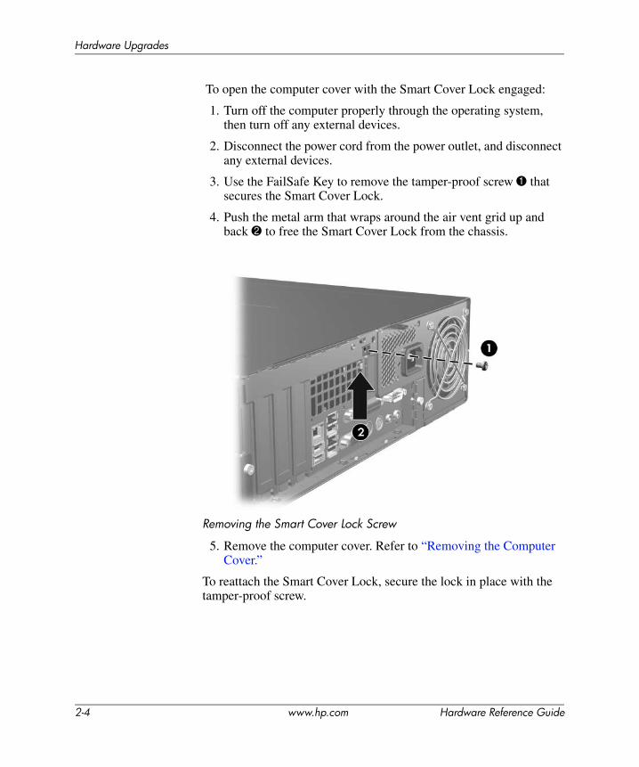
To open the computer cover with the Smart Cover Lock engaged:
1. Turn off the computer properly through the operating system, then turn off any external devices.
2. Disconnect the power cord from the power outlet, and disconnect any external devices.
3. Use the FailSafe Key to remove the tamper-proof screw 1 that secures the Smart Cover Lock.
4. Push the metal arm that wraps around the air vent grid up and back 2 to free the Smart Cover Lock from the chassis.
Removing the Smart Cover Lock Screw
5. Remove the computer cover. Refer to “Removing the Computer Cover.”
To reattach the Smart Cover Lock, secure the lock in place with the tamper-proof screw.
2-4 www.hp.com Hardware Reference Guide
Hardware Upgrades
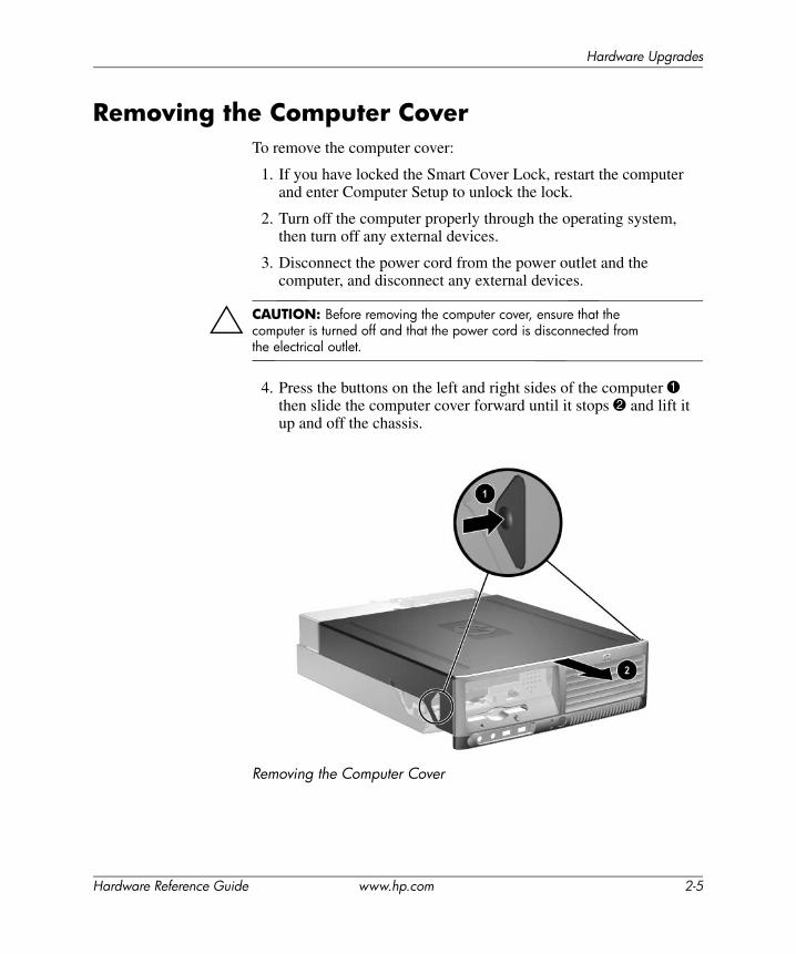
Removing the Computer CoverTo remove the computer cover:
1. If you have locked the Smart Cover Lock, restart the computer and enter Computer Setup to unlock the lock.
2. Turn off the computer properly through the operating system, then turn off any external devices.
3. Disconnect the power cord from the power outlet and the computer, and disconnect any external devices.
ÄCAUTION: Before removing the computer cover, ensure that the computer is turned off and that the power cord is disconnected from the electrical outlet.
4. Press the buttons on the left and right sides of the computer 1 then slide the computer cover forward until it stops 2 and lift it up and off the chassis.
Removing the Computer Cover
Hardware Reference Guide www.hp.com 2-5
Hardware Upgrades
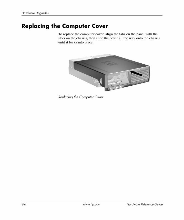
Replacing the Computer CoverTo replace the computer cover, align the tabs on the panel with the slots on the chassis, then slide the cover all the way onto the chassis until it locks into place.
Replacing the Computer Cover
2-6 www.hp.com Hardware Reference Guide

Hardware Upgrades
Installing Additional MemoryThe computer comes with double data rate 2 synchronous dynamic random access memory (DDR2-SDRAM) dual inline memory modules (DIMMs).
DIMMsThe memory sockets on the system board can be populated with up to four industry-standard DIMMs. These memory sockets are populated with at least one preinstalled DIMM. To achieve the maximum memory support, you can populate the system board with up to 4GB of memory configured in a high-performing dual channel mode.
DDR2-SDRAM DIMMsFor proper system operation, the DDR2-SDRAM DIMMs must be:
■ industry-standard 240-pin
■ unbuffered PC2-4200 533 MHz
■ 1.8 volt DDR2-SDRAM DIMMs
The DDR2-SDRAM DIMMs must also:
■ support CAS latency 4 (CL = 4) for DDR2/533 MHz
■ contain the mandatory JEDEC SPD information
In addition, the computer supports:
■ 256Mbit, 512Mbit, and 1Gbit non-ECC memory technologies
■ single-sided and double-sided DIMMS
■ DIMMs constructed with x8 and x16 DDR devices; DIMMs constructed with x4 SDRAM are not supported
✎ The system will not start if you install unsupported DIMMs.
Hardware Reference Guide www.hp.com 2-7
Hardware Upgrades
Populating DIMM SocketsThe system will automatically operate in single channel mode, dual channel Asymmetric mode, or a higher-performing dual channel Interleaved mode, depending on how the DIMMs are installed.
■ The system will operate in single channel mode if the DIMM sockets are populated in one channel only.
■ The system will operate in dual channel Asymmetric mode if the total memory capacity of the DIMMs in Channel A is not equal to the total memory capacity of the DIMMs in Channel B.
■ The system will operate in a higher-performing dual channel Interleaved mode if the total memory capacity of the DIMMs in Channel A is equal to the total memory capacity of the DIMMs in Channel B. However, the technology and device width can vary between the channels. For example, if Channel A is populated with two 256MB DIMMS and Channel B is populated with one 512MB DIMM, the system will operate in Interleaved mode.
■ In any mode, the maximum operational speed is determined by the slowest DIMM in the system.
2-8 www.hp.com Hardware Reference Guide
Hardware Upgrades
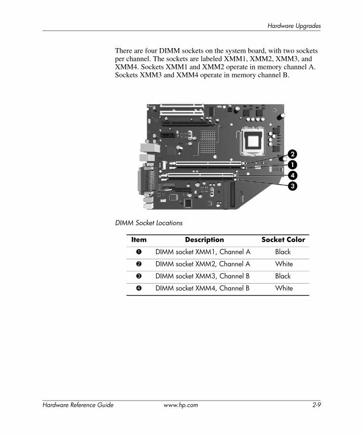
There are four DIMM sockets on the system board, with two sockets per channel. The sockets are labeled XMM1, XMM2, XMM3, and XMM4. Sockets XMM1 and XMM2 operate in memory channel A. Sockets XMM3 and XMM4 operate in memory channel B.
DIMM Socket Locations
Item Description Socket Color
1 DIMM socket XMM1, Channel A Black
2 DIMM socket XMM2, Channel A White
3 DIMM socket XMM3, Channel B Black
4 DIMM socket XMM4, Channel B White
Hardware Reference Guide www.hp.com 2-9

Hardware Upgrades
Installing DIMMs
ÄCAUTION: The memory module sockets have gold metal contacts. When upgrading the memory, it is important to use memory modules with gold metal contacts to prevent corrosion and/or oxidation resulting from having incompatible metals in contact with each other.
ÄCAUTION: Static electricity can damage the electronic components of the computer or optional cards. Before beginning these procedures, ensure that you are discharged of static electricity by briefly touching a grounded metal object. Refer to Appendix D, “Electrostatic Discharge” for more information.
ÄCAUTION: When handling a memory module, be careful not to touch any of the contacts. Doing so may damage the module.
1. If you have locked the Smart Cover Lock, restart the computer and enter Computer Setup to unlock the lock.
2. Turn off the computer properly through the operating system, then turn off any external devices.
3. Disconnect the power cord from the power outlet and disconnect any external devices.
4. Remove the computer cover. Refer to “Removing the Computer Cover.”
5. Locate the memory module sockets on the system board.
ÅWARNING: To reduce risk of personal injury from hot surfaces, allow the internal system components to cool before touching.
2-10 www.hp.com Hardware Reference Guide
Hardware Upgrades
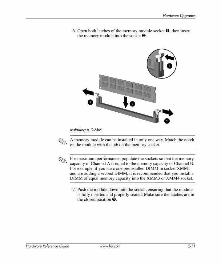
6. Open both latches of the memory module socket 1, then insert the memory module into the socket 2.
Installing a DIMM
✎ A memory module can be installed in only one way. Match the notch on the module with the tab on the memory socket.
✎ For maximum performance, populate the sockets so that the memory capacity of Channel A is equal to the memory capacity of Channel B. For example, if you have one preinstalled DIMM in socket XMM1 and are adding a second DIMM, it is recommended that you install a DIMM of equal memory capacity into the XMM3 or XMM4 socket.
7. Push the module down into the socket, ensuring that the module is fully inserted and properly seated. Make sure the latches are in the closed position 3.
Hardware Reference Guide www.hp.com 2-11
Hardware Upgrades
8. Repeat steps 6 and 7 for any additional modules that you want to install.
9. Replace the computer cover.
10. Plug in the power cord and turn on the computer.
11. If you normally lock the Smart Cover Lock, use Computer Setup to relock the lock and enable the Smart Cover Sensor.
The computer automatically recognizes the additional memory the first time you power on the computer.
2-12 www.hp.com Hardware Reference Guide

Hardware Upgrades
Installing an Expansion CardThe computer has two standard PCI expansion slots that can accommodate an expansion card up to 17.46 cm (6.875 inches) in length. The computer also has one PCI Express x1 expansion slot and one PCI Express x16 expansion slot.
✎ The PCI and PCI Express slots support only low profile cards unless an optional riser is installed. The optional riser supports two full height standard PCI slots. If the riser is installed, the PCI Express x16 expansion slot is inaccessible.
Expansion Slot Locations
✎ You can install a PCI Express x1, x4, x8, or x16 expansion card in the PCI Express x16 expansion slot.
Item Description
1 PCI expansion slot
2 PCI expansion slot
3 PCI Express x16 expansion slot
4 PCI Express x1 expansion slot
Hardware Reference Guide www.hp.com 2-13
Hardware Upgrades
To install an expansion card:
1. If you have locked the Smart Cover Lock, restart the computer and enter Computer Setup to unlock the lock.
2. Turn off the computer properly through the operating system, then turn off any external devices.
3. Disconnect the power cord from the power outlet and disconnect any external devices.
4. Remove the computer cover. Refer to “Removing the Computer Cover.”
5. Identify the slot into which you want to insert the expansion card.
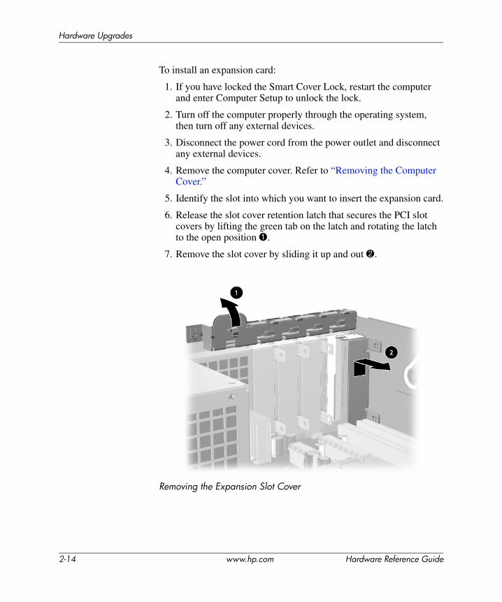
6. Release the slot cover retention latch that secures the PCI slot covers by lifting the green tab on the latch and rotating the latch to the open position 1.
7. Remove the slot cover by sliding it up and out 2.
Removing the Expansion Slot Cover
2-14 www.hp.com Hardware Reference Guide
Hardware Upgrades
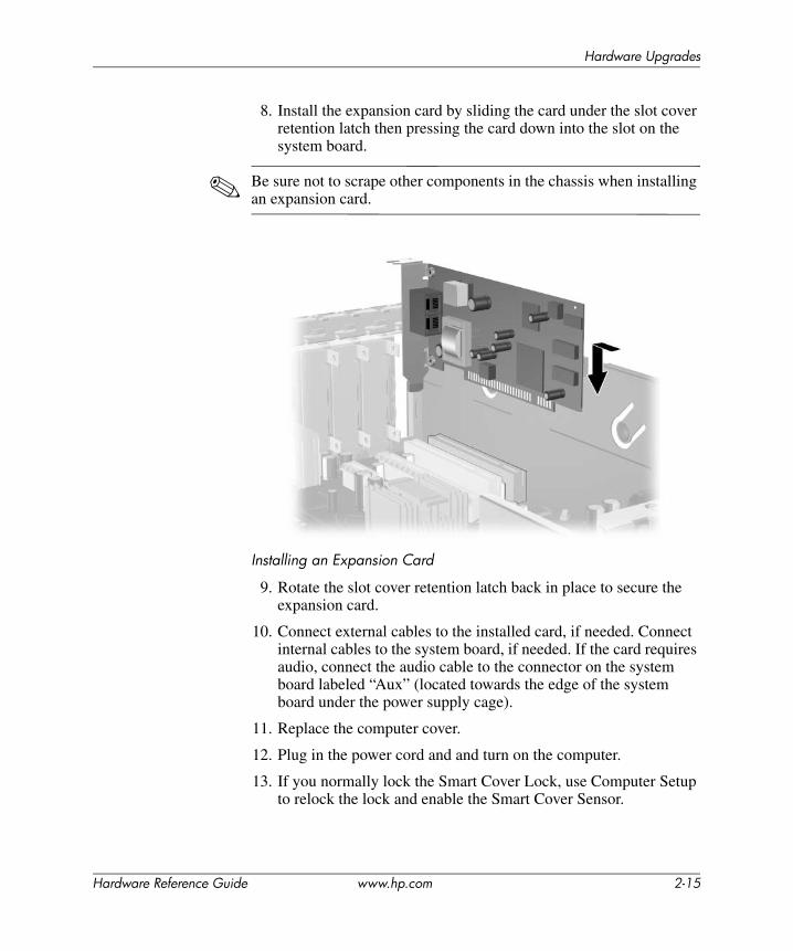
8. Install the expansion card by sliding the card under the slot cover retention latch then pressing the card down into the slot on the system board.
✎ Be sure not to scrape other components in the chassis when installing an expansion card.
Installing an Expansion Card
9. Rotate the slot cover retention latch back in place to secure the expansion card.
10. Connect external cables to the installed card, if needed. Connect internal cables to the system board, if needed. If the card requires audio, connect the audio cable to the connector on the system board labeled “Aux” (located towards the edge of the system board under the power supply cage).
11. Replace the computer cover.
12. Plug in the power cord and and turn on the computer.
13. If you normally lock the Smart Cover Lock, use Computer Setup to relock the lock and enable the Smart Cover Sensor.
Hardware Reference Guide www.hp.com 2-15
Hardware Upgrades
14. Reconfigure the computer, if necessary. Refer to the Computer Setup (F10) Utility Guide on the Documentation and Diagnostics CD for instructions about using Computer Setup.
✎ When you install an expansion card, make sure the metal bracket on the card slides into the slot on the back of the computer then press down firmly on the card so that the whole connector seats properly in the expansion card slot.
ÄCAUTION: All expansion card slots on the rear of the computer must contain either an expansion card or slot cover for proper cooling of internal components during operation.
2-16 www.hp.com Hardware Reference Guide
Hardware Upgrades
Removing a PCI Express x16 Expansion CardTo remove a PCI Express x16 expansion card:
1. If you have locked the Smart Cover Lock, restart the computer and enter Computer Setup to unlock the lock.
2. Turn off the computer properly through the operating system, then turn off any external devices.
3. Disconnect the power cord from the power outlet and disconnect any external devices.
4. Remove the computer cover. Refer to “Removing the Computer Cover.”
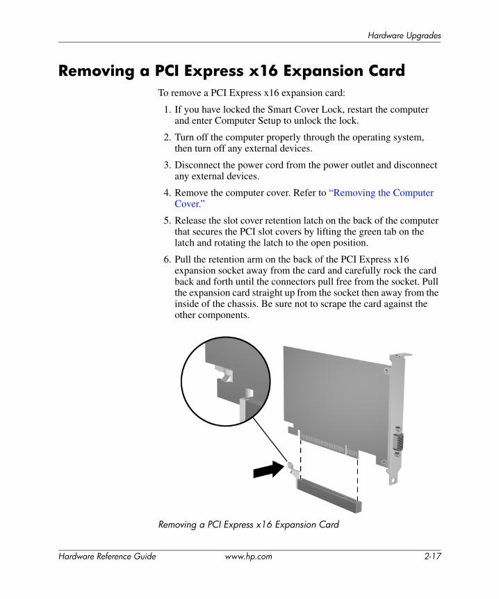
5. Release the slot cover retention latch on the back of the computer that secures the PCI slot covers by lifting the green tab on the latch and rotating the latch to the open position.
6. Pull the retention arm on the back of the PCI Express x16 expansion socket away from the card and carefully rock the card back and forth until the connectors pull free from the socket. Pull the expansion card straight up from the socket then away from the inside of the chassis. Be sure not to scrape the card against the other components.
Removing a PCI Express x16 Expansion Card
Hardware Reference Guide www.hp.com 2-17
Hardware Upgrades
7. Store the card in anti-static packaging.
8. If you are not installing a new expansion card, install an expansion slot cover to close the open slot.
9. Rotate the slot cover retention latch back in place to secure the expansion cards and expansion slot covers.
10. Replace the computer cover.
11. Plug in the power cord and and turn on the computer.
12. If you normally lock the Smart Cover Lock, use Computer Setup to relock the lock and enable the Smart Cover Sensor.
ÄCAUTION: All expansion card slots on the rear of the computer must contain either an expansion card or slot cover for proper cooling of internal components during operation.
2-18 www.hp.com Hardware Reference Guide
Hardware Upgrades
Installing Additional DrivesThe computer has two external drive bays. When installing additional drives, follow these guidelines:
■ The primary Serial ATA (SATA) hard drive should be connected to the primary SATA controller on the system board (blue and labeled P60 SATA 0). Connect a second SATA hard drive to the secondary SATA controller on the system board (white and labeled P61 SATA 1). HP does not support connecting both SATA and 3.5-inch PATA hard drives on the same system.
■ Connect Parallel ATA (PATA) expansion devices, such as optical, IDE tape, and Zip drives, to the PATA controller (labeled P20 PRIMARY IDE) using a standard 80-conductor cable.
■ Install guide screws to ensure the drive will line up correctly in the drive cage and lock in place. HP has provided extra guide screws (four 6-32 standard screws and four M3 metric screws), installed in the front of the chassis, under the computer cover. The hard drive uses 6-32 standard screws. All other drives use M3 metric screws. The HP-supplied metric screws are black and the HP-supplied standard screws are silver.
ÄCAUTION: To prevent loss of work and damage to the computer or drive:■ If you are inserting or removing a hard drive, shut down the operating
system properly, then turn off the computer. Do not remove a hard drive while the computer is on or in standby mode.
■ Before handling a drive, ensure that you are discharged of static electricity. While handling a drive, avoid touching the connector. For more information about preventing electrostatic damage, see Appendix D, “Electrostatic Discharge.”
■ Handle a drive carefully; do not drop it.■ Do not use excessive force when inserting a drive.■ Avoid exposing a hard drive to liquids, temperature extremes, or
products that have magnetic fields such as monitors or speakers.■ If a drive must be mailed, place the drive in a bubble-pack mailer or
other suitable protective packaging and label the package “Fragile: Handle With Care.”
Hardware Reference Guide www.hp.com 2-19
Hardware Upgrades
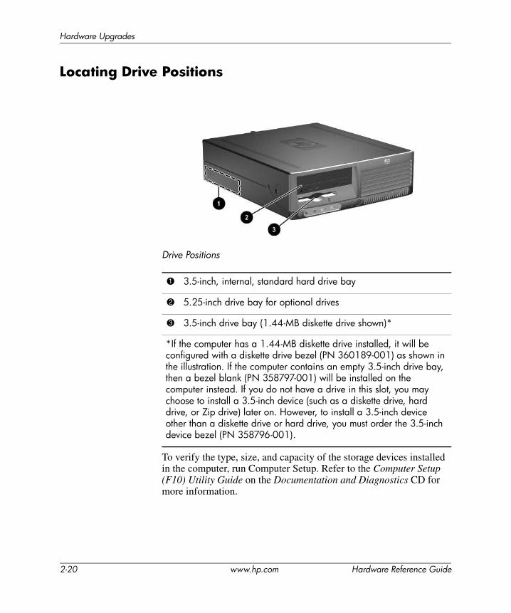
Locating Drive Positions
Drive Positions
To verify the type, size, and capacity of the storage devices installed in the computer, run Computer Setup. Refer to the Computer Setup (F10) Utility Guide on the Documentation and Diagnostics CD for more information.
1 3.5-inch, internal, standard hard drive bay
2 5.25-inch drive bay for optional drives
3 3.5-inch drive bay (1.44-MB diskette drive shown)*
*If the computer has a 1.44-MB diskette drive installed, it will be configured with a diskette drive bezel (PN 360189-001) as shown in the illustration. If the computer contains an empty 3.5-inch drive bay, then a bezel blank (PN 358797-001) will be installed on the computer instead. If you do not have a drive in this slot, you may choose to install a 3.5-inch device (such as a diskette drive, hard drive, or Zip drive) later on. However, to install a 3.5-inch device other than a diskette drive or hard drive, you must order the 3.5-inch device bezel (PN 358796-001).
2-20 www.hp.com Hardware Reference Guide
Hardware Upgrades
Removing an Optical Drive
ÄCAUTION: All removable media should be taken out of the drives before removing the drive from the computer.
✎ An optical drive is a CD-ROM, CD-R/RW, DVD-ROM, DVD+R/RW, or CD-RW/DVD Combo drive.
To remove an optical drive:
1. If you have locked the Smart Cover Lock, restart the computer and enter Computer Setup to unlock the lock.
2. Turn off the computer properly through the operating system, then turn off any external devices.
3. Disconnect the power cord from the power outlet and disconnect any external devices.
4. Remove the computer cover. Refer to “Removing the Computer Cover.”
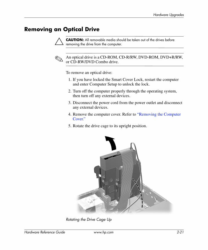
5. Rotate the drive cage to its upright position.
Rotating the Drive Cage Up
Hardware Reference Guide www.hp.com 2-21
Hardware Upgrades
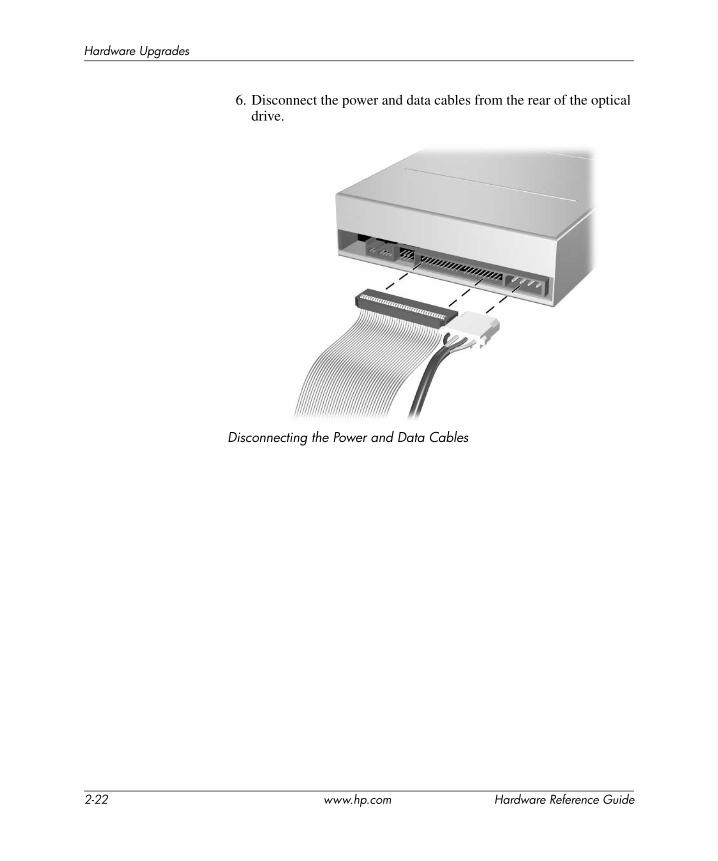
6. Disconnect the power and data cables from the rear of the optical drive.
Disconnecting the Power and Data Cables
2-22 www.hp.com Hardware Reference Guide
Hardware Upgrades
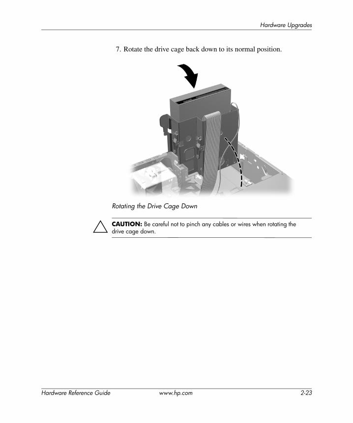
7. Rotate the drive cage back down to its normal position.
Rotating the Drive Cage Down
ÄCAUTION: Be careful not to pinch any cables or wires when rotating the drive cage down.
Hardware Reference Guide www.hp.com 2-23
Hardware Upgrades
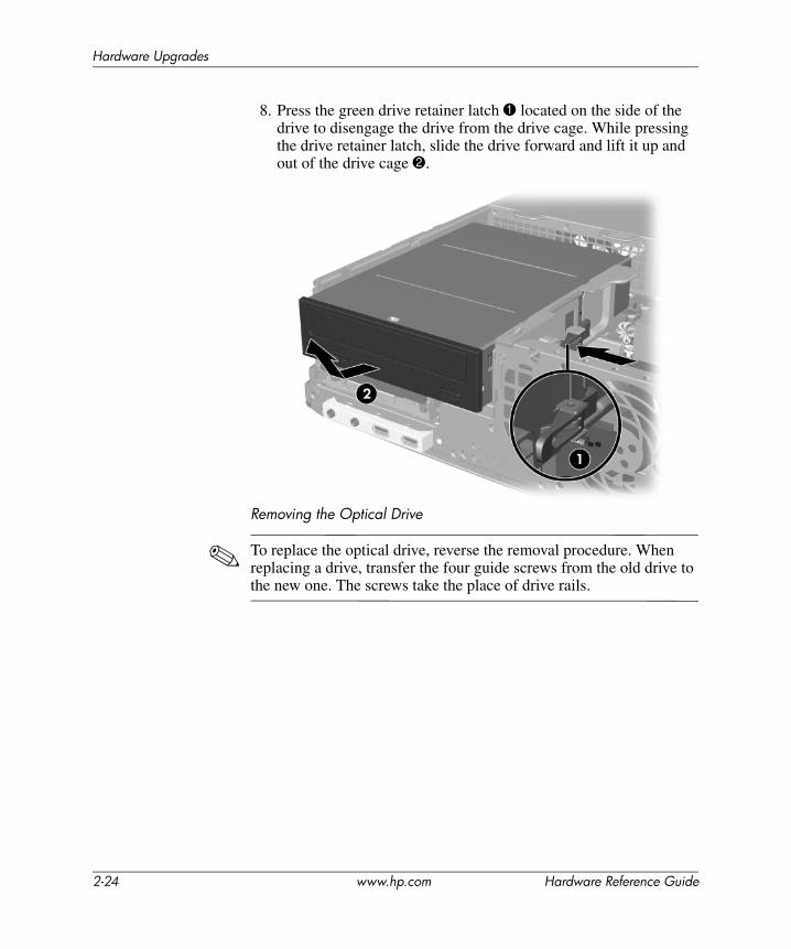
8. Press the green drive retainer latch 1 located on the side of the drive to disengage the drive from the drive cage. While pressing the drive retainer latch, slide the drive forward and lift it up and out of the drive cage 2.
Removing the Optical Drive
✎ To replace the optical drive, reverse the removal procedure. When replacing a drive, transfer the four guide screws from the old drive to the new one. The screws take the place of drive rails.
2-24 www.hp.com Hardware Reference Guide
Hardware Upgrades
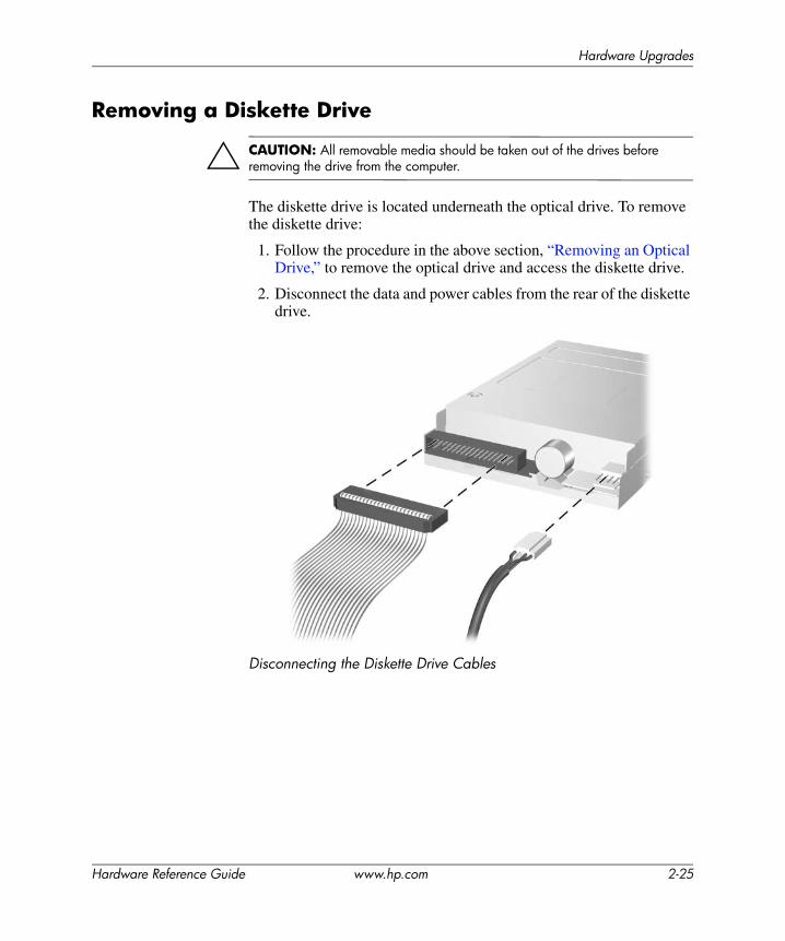
Removing a Diskette Drive
ÄCAUTION: All removable media should be taken out of the drives before removing the drive from the computer.
The diskette drive is located underneath the optical drive. To remove the diskette drive:
1. Follow the procedure in the above section, “Removing an Optical Drive,” to remove the optical drive and access the diskette drive.
2. Disconnect the data and power cables from the rear of the diskette drive.
Disconnecting the Diskette Drive Cables
Hardware Reference Guide www.hp.com 2-25

Hardware Upgrades
3. Press the green drive retention latch 1 located on the side of the diskette drive to disengage the drive from the drive cage and slide the diskette drive forward approximately 6mm (1/4 inch) 2.
Disengaging the Diskette Drive
2-26 www.hp.com Hardware Reference Guide
Hardware Upgrades
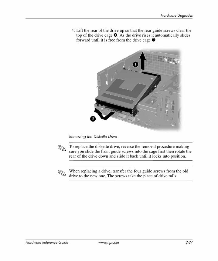
4. Lift the rear of the drive up so that the rear guide screws clear the top of the drive cage 1. As the drive rises it automatically slides forward until it is free from the drive cage 2.
Removing the Diskette Drive
✎ To replace the diskette drive, reverse the removal procedure making sure you slide the front guide screws into the cage first then rotate the rear of the drive down and slide it back until it locks into position.
✎ When replacing a drive, transfer the four guide screws from the old drive to the new one. The screws take the place of drive rails.
Hardware Reference Guide www.hp.com 2-27

Hardware Upgrades
Installing an Optional Optical DriveTo install an optional optical drive:
1. If you have locked the Smart Cover Lock, restart the computer and enter Computer Setup to unlock the lock.
2. Turn off the computer properly through the operating system, then turn off any external devices.
3. Disconnect the power cord from the power outlet and disconnect any external devices.
4. Remove the computer cover. Refer to “Removing the Computer Cover.”
5. Install two M3 metric guide screws in the lower holes on each side of the drive. HP has provided four extra M3 metric guide screws on the front of the chassis, under the computer cover. The M3 metric guide screws are black.
ÄCAUTION: Use only 5-mm long screws as guide screws. Longer screws can damage the internal components of the drive.
✎ When replacing the drive, transfer the four M3 metric guide screws from the old drive to the new one. The screws take the place of drive rails.
Installing Guide Screws in the Optical Drive
2-28 www.hp.com Hardware Reference Guide
Hardware Upgrades
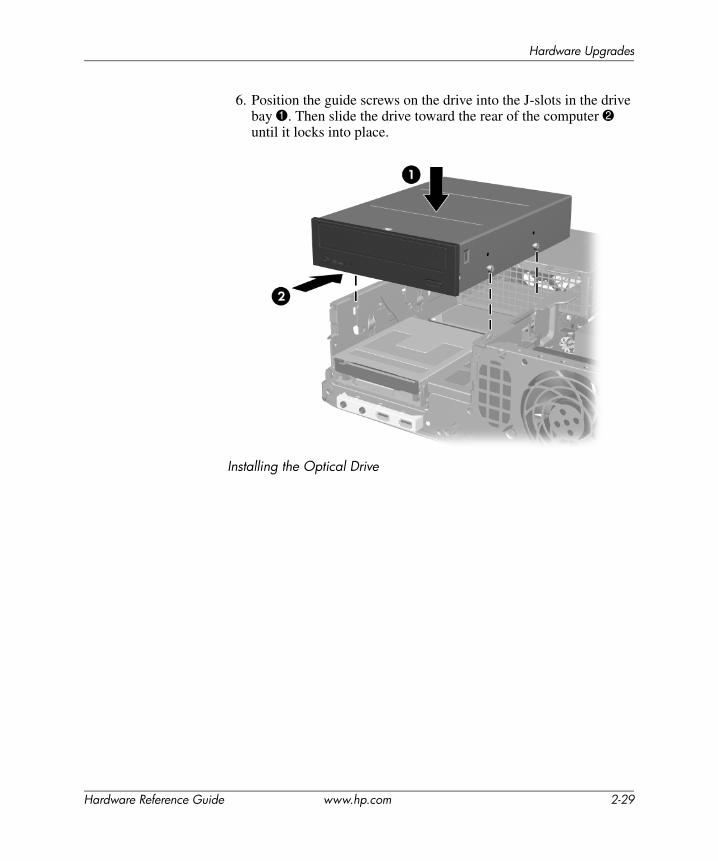
6. Position the guide screws on the drive into the J-slots in the drive bay 1. Then slide the drive toward the rear of the computer 2 until it locks into place.
Installing the Optical Drive
Hardware Reference Guide www.hp.com 2-29
Hardware Upgrades
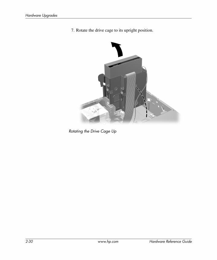
7. Rotate the drive cage to its upright position.
Rotating the Drive Cage Up
2-30 www.hp.com Hardware Reference Guide
Hardware Upgrades
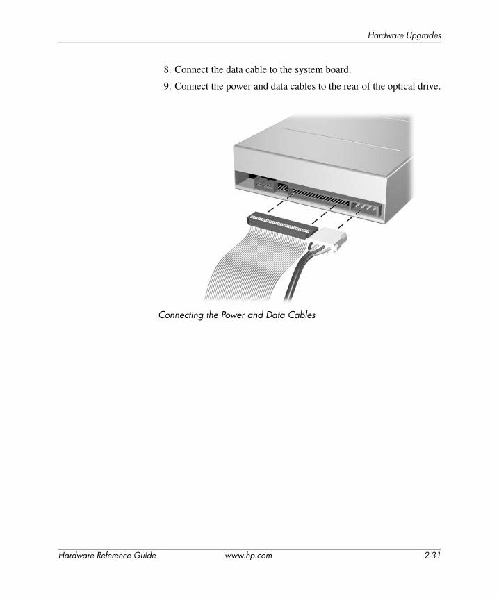
8. Connect the data cable to the system board.
9. Connect the power and data cables to the rear of the optical drive.
Connecting the Power and Data Cables
Hardware Reference Guide www.hp.com 2-31
Hardware Upgrades
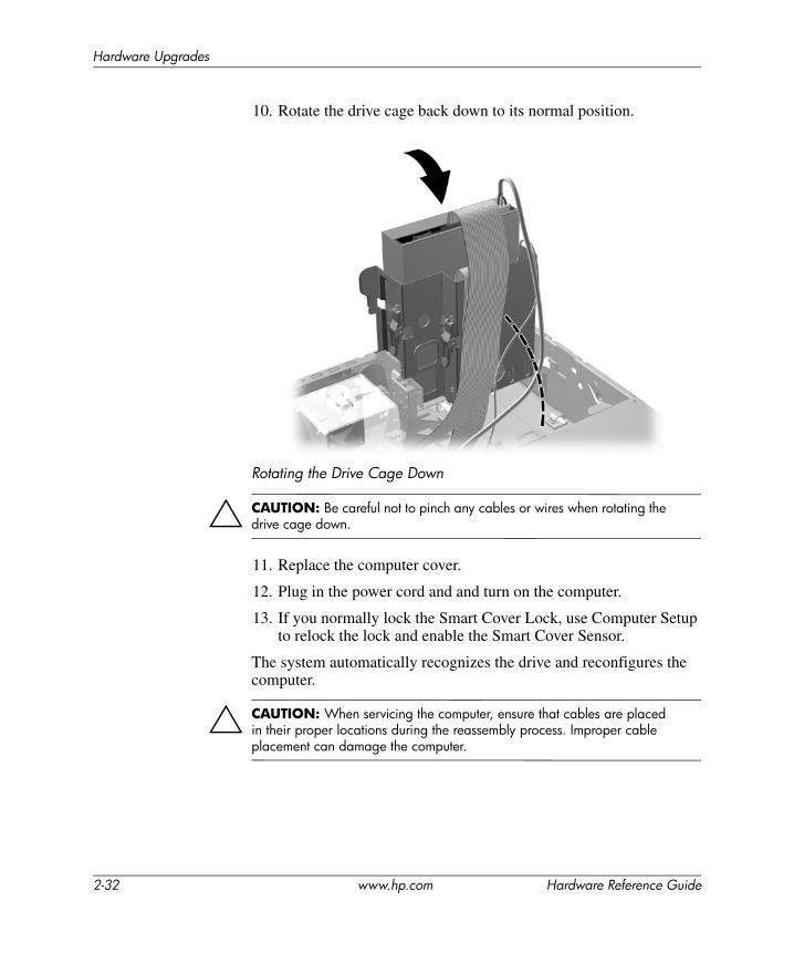
10. Rotate the drive cage back down to its normal position.
Rotating the Drive Cage Down
ÄCAUTION: Be careful not to pinch any cables or wires when rotating the drive cage down.
11. Replace the computer cover.
12. Plug in the power cord and and turn on the computer.
13. If you normally lock the Smart Cover Lock, use Computer Setup to relock the lock and enable the Smart Cover Sensor.
The system automatically recognizes the drive and reconfigures the computer.
ÄCAUTION: When servicing the computer, ensure that cables are placed in their proper locations during the reassembly process. Improper cable placement can damage the computer.
2-32 www.hp.com Hardware Reference Guide
Hardware Upgrades
Upgrading the SATA Hard Drive
✎ HP does not support connecting both SATA and 3.5-inch PATA hard drives on the same system.
Removing and Replacing the Primary Hard Drive
✎ Make sure to back up the data on the old hard drive before removing it so that you can install the data onto the new hard drive.
The preinstalled 3.5-inch hard drive is located under the power supply. To remove and replace the hard drive:
1. If you have locked the Smart Cover Lock, restart the computer and enter Computer Setup to unlock the lock.
2. Turn off the computer properly through the operating system, then turn off any external devices.
3. Disconnect the power cord from the power outlet and disconnect any external devices.
4. Remove the computer cover. Refer to “Removing the Computer Cover.”
Hardware Reference Guide www.hp.com 2-33
Hardware Upgrades
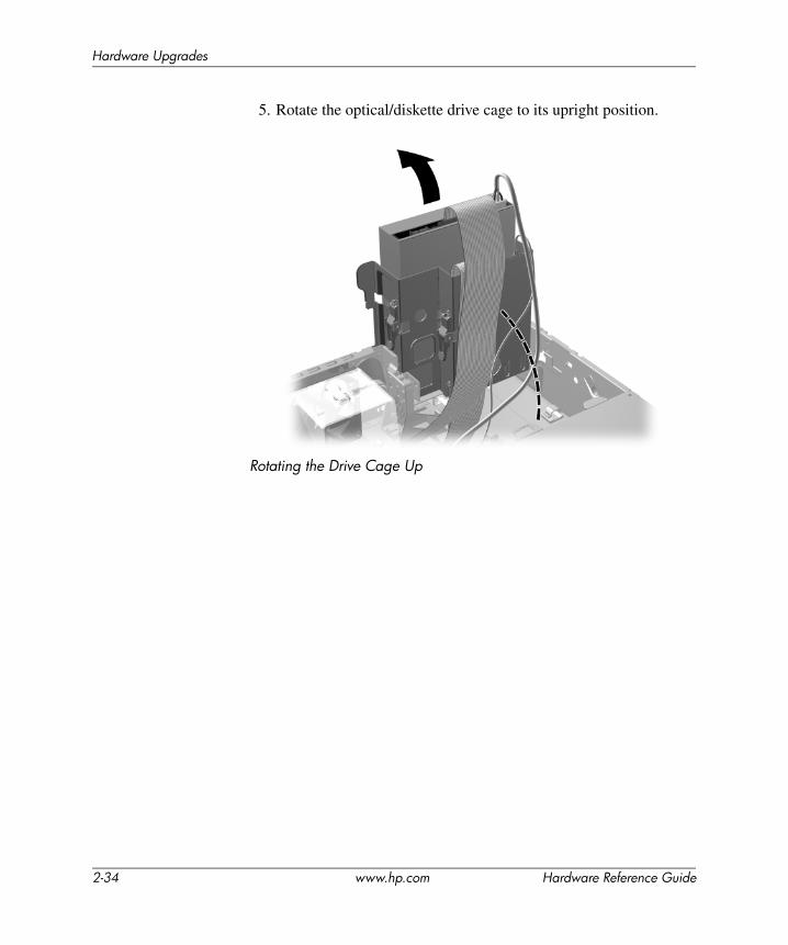
5. Rotate the optical/diskette drive cage to its upright position.
Rotating the Drive Cage Up
2-34 www.hp.com Hardware Reference Guide
Hardware Upgrades
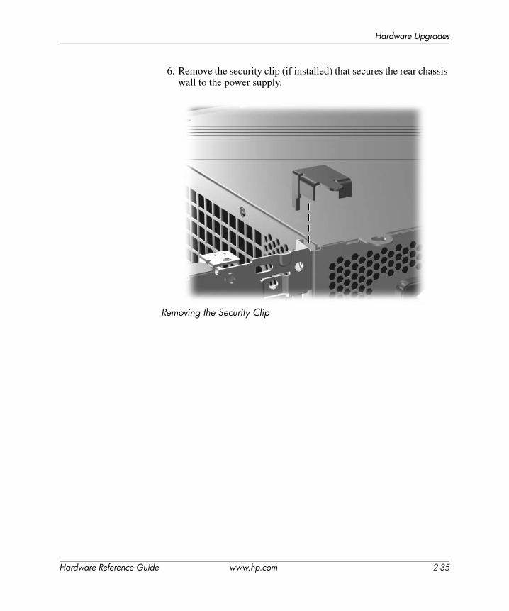
6. Remove the security clip (if installed) that secures the rear chassis wall to the power supply.
Removing the Security Clip
Hardware Reference Guide www.hp.com 2-35
Hardware Upgrades
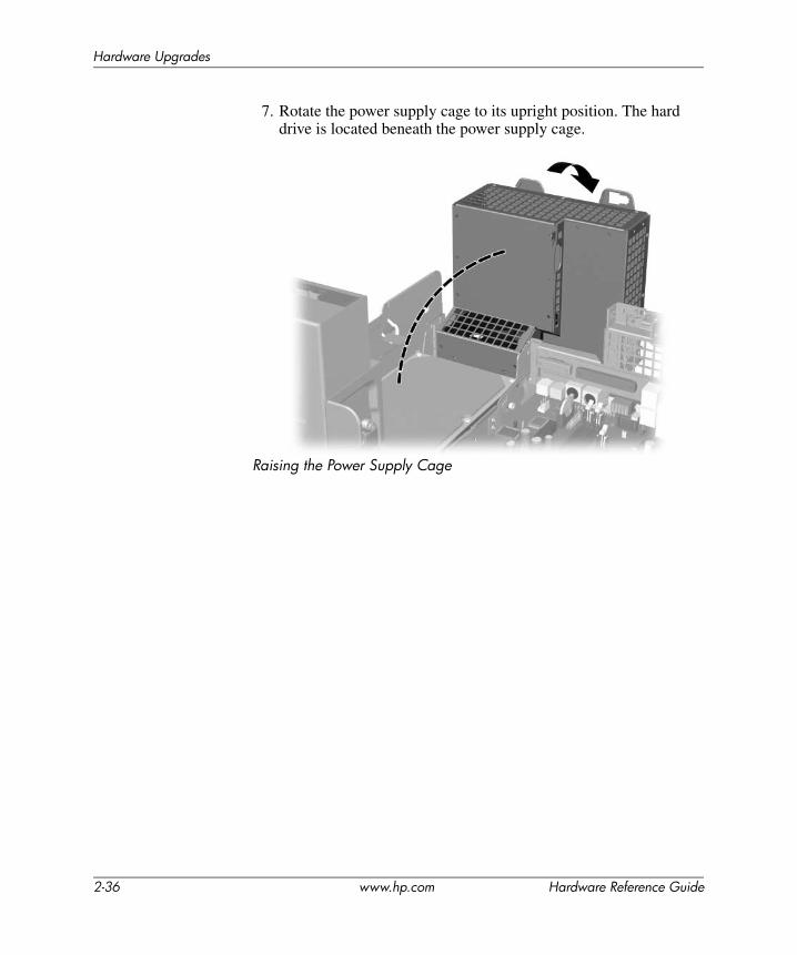
7. Rotate the power supply cage to its upright position. The hard drive is located beneath the power supply cage.
Raising the Power Supply Cage
2-36 www.hp.com Hardware Reference Guide

Hardware Upgrades
8. Disconnect the power cable 1 and data cable 2 from the back of the hard drive.
Disconnecting the Hard Drive Power Cable and Data Cable
Hardware Reference Guide www.hp.com 2-37
Hardware Upgrades
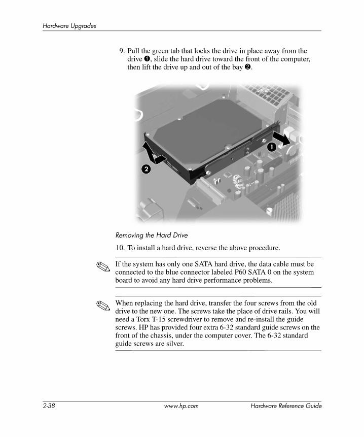
9. Pull the green tab that locks the drive in place away from the drive 1, slide the hard drive toward the front of the computer, then lift the drive up and out of the bay 2.
Removing the Hard Drive
10. To install a hard drive, reverse the above procedure.
✎ If the system has only one SATA hard drive, the data cable must be connected to the blue connector labeled P60 SATA 0 on the system board to avoid any hard drive performance problems.
✎ When replacing the hard drive, transfer the four screws from the old drive to the new one. The screws take the place of drive rails. You will need a Torx T-15 screwdriver to remove and re-install the guide screws. HP has provided four extra 6-32 standard guide screws on the front of the chassis, under the computer cover. The 6-32 standard guide screws are silver.
2-38 www.hp.com Hardware Reference Guide
Hardware Upgrades
✎ If you replaced the primary hard drive, insert the Restore Plus! CD to restore the operating system, software drivers, and any software applications that were preinstalled on the computer. Follow the instructions in the guide included with the Restore Plus! CD. When the restore process has completed, reinstall any personal files that you backed up before replacing the hard drive.
Installing an Optional Drive into the 3.5-inch Drive BayDepending on the computer configuration, the 3.5-inch drive bay on the front of the computer may be configured with a diskette drive or it may be an empty drive bay. The type of bezel covering the drive bay will vary depending on the original computer configuration.
If the computer was not configured with a diskette drive, you can install a 3.5-inch device, such as a diskette drive or hard drive, into the drive bay.
✎ The type of bezel you need will depend on the type of device you plan to install. If you are installing a diskette drive, you must install a diskette drive bezel (PN 360189-001). If you are installing a hard drive, you must install a bezel blank (PN 358797-001). If you are installing a 3.5-inch device other than a diskette drive or hard drive, you must install the 3.5-inch device bezel (PN 358796-001). Contact an authorized HP reseller or service provider to order the appropriate bezel when reconfiguring the computer.
Hardware Reference Guide www.hp.com 2-39
Hardware Upgrades
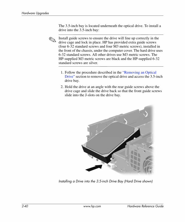
The 3.5-inch bay is located underneath the optical drive. To install a drive into the 3.5-inch bay:
✎ Install guide screws to ensure the drive will line up correctly in the drive cage and lock in place. HP has provided extra guide screws (four 6-32 standard screws and four M3 metric screws), installed in the front of the chassis, under the computer cover. The hard drive uses 6-32 standard screws. All other drives use M3 metric screws. The HP-supplied M3 metric screws are black and the HP-supplied 6-32 standard screws are silver.
1. Follow the procedure described in the “Removing an Optical Drive” section to remove the optical drive and access the 3.5-inch drive bay.
2. Hold the drive at an angle with the rear guide screws above the drive cage and slide the drive back so that the front guide screws slide into the J-slots on the drive bay.
Installing a Drive into the 3.5-inch Drive Bay (Hard Drive shown)
2-40 www.hp.com Hardware Reference Guide
Hardware Upgrades
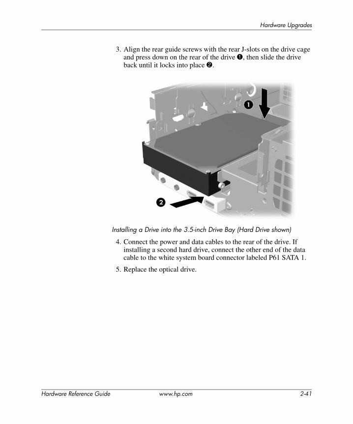
3. Align the rear guide screws with the rear J-slots on the drive cage and press down on the rear of the drive 1, then slide the drive back until it locks into place 2.
Installing a Drive into the 3.5-inch Drive Bay (Hard Drive shown)
4. Connect the power and data cables to the rear of the drive. If installing a second hard drive, connect the other end of the data cable to the white system board connector labeled P61 SATA 1.
5. Replace the optical drive.
Hardware Reference Guide www.hp.com 2-41
Hardware Upgrades
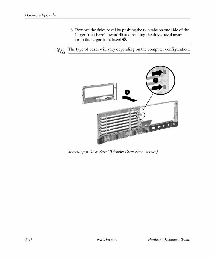
6. Remove the drive bezel by pushing the two tabs on one side of the larger front bezel inward 1 and rotating the drive bezel away from the larger front bezel 2.
✎ The type of bezel will vary depending on the computer configuration.
Removing a Drive Bezel (Diskette Drive Bezel shown)
2-42 www.hp.com Hardware Reference Guide
Hardware Upgrades
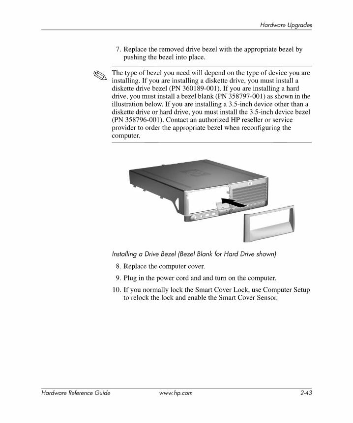
7. Replace the removed drive bezel with the appropriate bezel by pushing the bezel into place.
✎ The type of bezel you need will depend on the type of device you are installing. If you are installing a diskette drive, you must install a diskette drive bezel (PN 360189-001). If you are installing a hard drive, you must install a bezel blank (PN 358797-001) as shown in the illustration below. If you are installing a 3.5-inch device other than a diskette drive or hard drive, you must install the 3.5-inch device bezel (PN 358796-001). Contact an authorized HP reseller or service provider to order the appropriate bezel when reconfiguring the computer.
Installing a Drive Bezel (Bezel Blank for Hard Drive shown)
8. Replace the computer cover.
9. Plug in the power cord and and turn on the computer.
10. If you normally lock the Smart Cover Lock, use Computer Setup to relock the lock and enable the Smart Cover Sensor.
Hardware Reference Guide www.hp.com 2-43

ASpecifications
Ensure at least 4 inches (10.2 cm) of space on all sides remains clear and free of obstructions.
HP Compaq Small Form Factor
Desktop Dimensions
Height 3.95 inches 10.3 cm
Width 13.3 inches 33.78 cm
Depth (depth will increase if the computer is equipped with a port security bracket)
14.9 inches 37.85 cm
Approximate Weight 21 lb 9.53 kg
Temperature Range
Operating 50° to 95° F 10° to 35° C
Nonoperating -22° to 140° F -30° to 60° C
Relative Humidity (noncondensing)
Operating 10–90% 10–90%
Nonoperating (38.7° C max wet bulb) 5–95% 5–95%
Maximum Altitude (unpressurized)
Operating 10,000 ft 3048 m
Nonoperating 30,000 ft 9144 m
✎ Operating temperature is derated 1.0° C per 300 m (1000 ft) to 3000 m (10,000 ft) above sea level; no direct sustained sunlight. Maximum rate of change is 10° C/Hr. The upper limit may be limited by the type and number of options installed.
Hardware Reference Guide www.hp.com A-1
Specifications
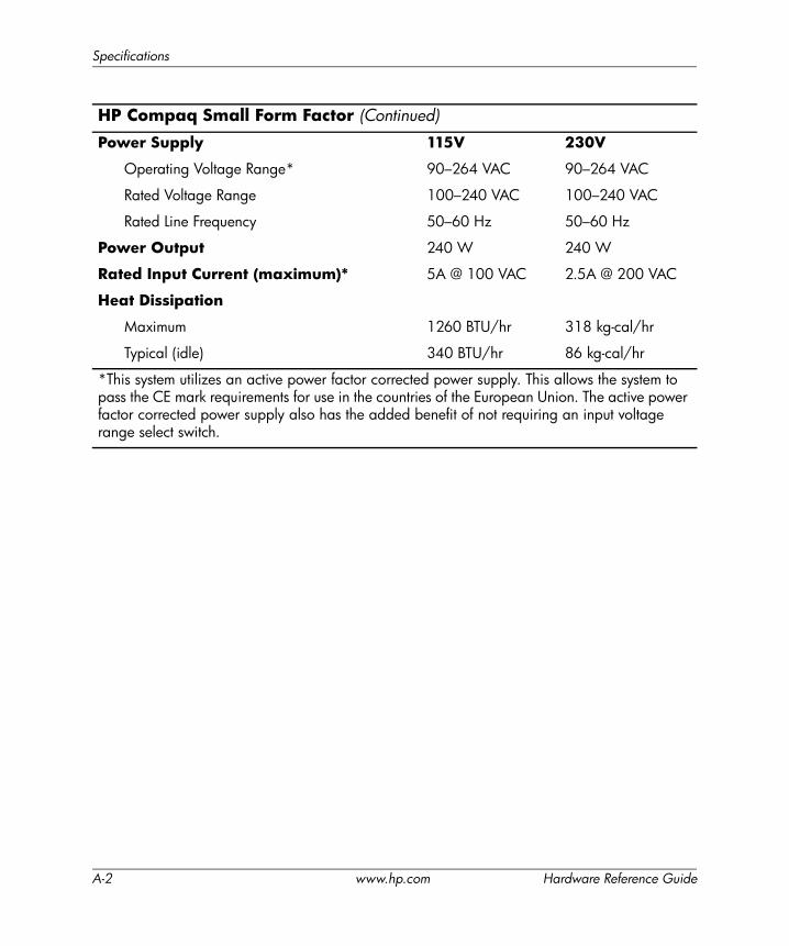
Power Supply 115V 230V
Operating Voltage Range* 90–264 VAC 90–264 VAC
Rated Voltage Range 100–240 VAC 100–240 VAC
Rated Line Frequency 50–60 Hz 50–60 Hz
Power Output 240 W 240 W
Rated Input Current (maximum)* 5A @ 100 VAC 2.5A @ 200 VAC
Heat Dissipation
Maximum 1260 BTU/hr 318 kg-cal/hr
Typical (idle) 340 BTU/hr 86 kg-cal/hr
*This system utilizes an active power factor corrected power supply. This allows the system to pass the CE mark requirements for use in the countries of the European Union. The active power factor corrected power supply also has the added benefit of not requiring an input voltage range select switch.
HP Compaq Small Form Factor (Continued)
A-2 www.hp.com Hardware Reference Guide
BBattery Replacement
The battery that comes with the computer provides power to the real-time clock. When replacing the battery, use a battery equivalent to the battery originally installed in the computer. The computer comes with a 3-volt lithium coin cell battery.
✎ The lifetime of the lithium battery can be extended by plugging the computer into a live AC wall socket. The lithium battery is only used when the computer is NOT connected to AC power.
ÅWARNING: The computer contains an internal lithium manganese dioxide battery. There is a risk of fire and burns if the battery is not handled properly. To reduce the risk of personal injury:■ Do not attempt to recharge the battery.■ Do not expose to temperatures higher than 60° C (140º F).■ Do not disassemble, crush, puncture, short external contacts, or
dispose of in fire or water.■ Replace the battery only with the HP spare designated for this product.
ÄCAUTION: Before replacing the battery, it is important to back up the computer CMOS settings. When the battery is removed or replaced, the CMOS settings will be cleared. Refer to the Computer Setup (F10) Utility Guide on the Documentation and Diagnostics CD for information on backing up the CMOS settings.
NBatteries, battery packs, and accumulators should not be disposed of together with the general household waste. In order to forward them to recycling or proper disposal, please use the public collection system or return them to HP, their authorized partners, or their agents.
Hardware Reference Guide www.hp.com B-1
Battery Replacement
ÄCAUTION: Static electricity can damage the electronic components of the computer or optional equipment. Before beginning these procedures, ensure that you are discharged of static electricity by briefly touching a grounded metal object.
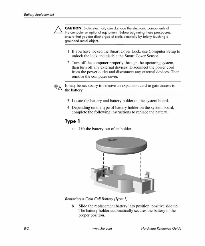
1. If you have locked the Smart Cover Lock, use Computer Setup to unlock the lock and disable the Smart Cover Sensor.
2. Turn off the computer properly through the operating system, then turn off any external devices. Disconnect the power cord from the power outlet and disconnect any external devices. Then remove the computer cover.
✎ It may be necessary to remove an expansion card to gain access to the battery.
3. Locate the battery and battery holder on the system board.
4. Depending on the type of battery holder on the system board, complete the following instructions to replace the battery.
Type 1a. Lift the battery out of its holder.
Removing a Coin Cell Battery (Type 1)
b. Slide the replacement battery into position, positive side up. The battery holder automatically secures the battery in the proper position.
B-2 www.hp.com Hardware Reference Guide
Battery Replacement
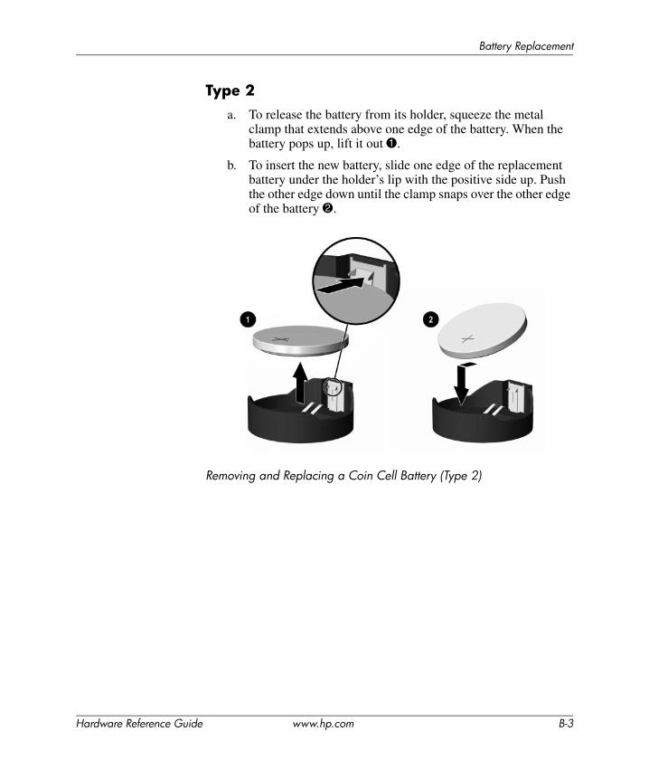
Type 2a. To release the battery from its holder, squeeze the metal
clamp that extends above one edge of the battery. When the battery pops up, lift it out 1.
b. To insert the new battery, slide one edge of the replacement battery under the holder’s lip with the positive side up. Push the other edge down until the clamp snaps over the other edge of the battery 2.
Removing and Replacing a Coin Cell Battery (Type 2)
Hardware Reference Guide www.hp.com B-3

Battery Replacement
Type 3a. Pull back on the clip 1 that is holding the battery in place,
and remove the battery 2.
b. Insert the new battery and position the clip back into place.
Removing a Coin Cell Battery (Type 3)
✎ After the battery has been replaced, use the following steps to complete this procedure.
5. Replace the computer cover.
6. Plug in the computer and turn on power to the computer.
7. Reset the date and time, your passwords, and any special system setups, using Computer Setup. Refer to the Computer Setup (F10) Utility Guide on the Documentation and Diagnostics CD.
8. If you normally lock the Smart Cover Lock, use Computer Setup to relock the lock and enable the Smart Cover Sensor.
B-4 www.hp.com Hardware Reference Guide
CSecurity Lock Provisions
✎ For information on data security features, refer to the Computer Setup (F10) Utility Guide and the Desktop Management Guide on the Documentation and Diagnostics CD and the HP ProtectTools Security Manager Guide (some models) at www.hp.com.
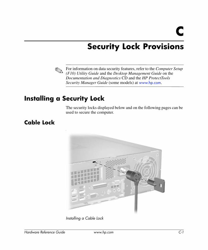
Installing a Security LockThe security locks displayed below and on the following pages can be used to secure the computer.
Cable LockI
Installing a Cable Lock
Hardware Reference Guide www.hp.com C-1
Security Lock Provisions
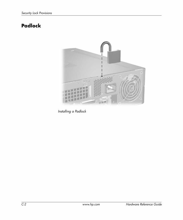
Padlock
Installing a Padlock
C-2 www.hp.com Hardware Reference Guide
Security Lock Provisions
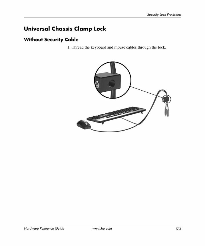
Universal Chassis Clamp Lock
Without Security Cable1. Thread the keyboard and mouse cables through the lock.
Hardware Reference Guide www.hp.com C-3
Security Lock Provisions
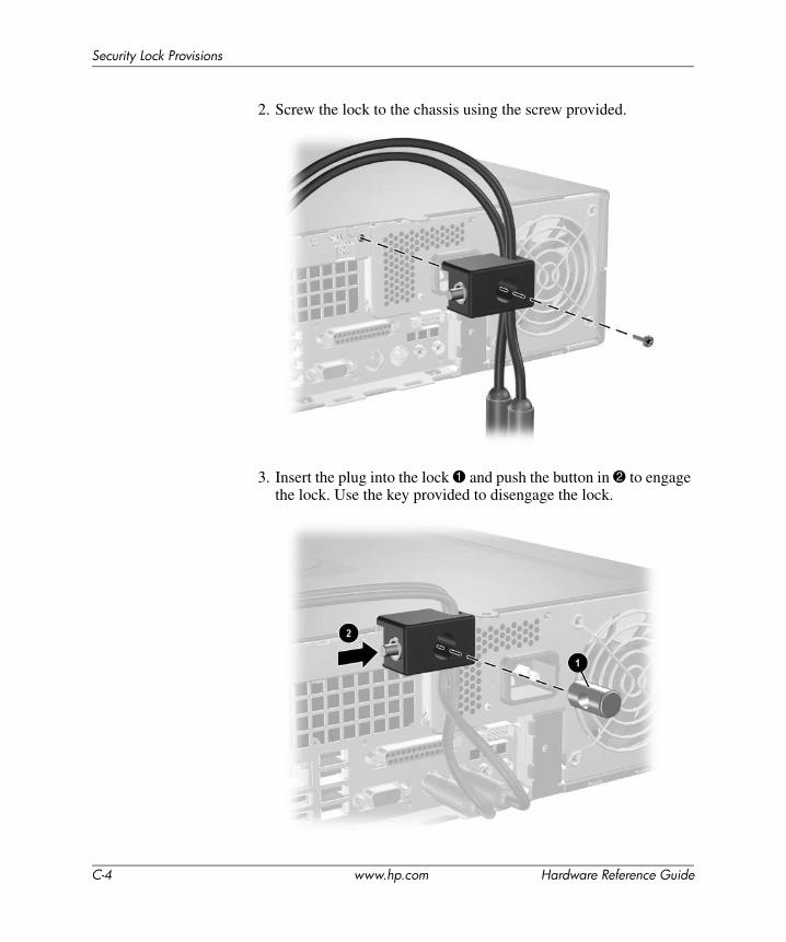
2. Screw the lock to the chassis using the screw provided.
3. Insert the plug into the lock 1 and push the button in 2 to engage the lock. Use the key provided to disengage the lock.
C-4 www.hp.com Hardware Reference Guide
Security Lock Provisions
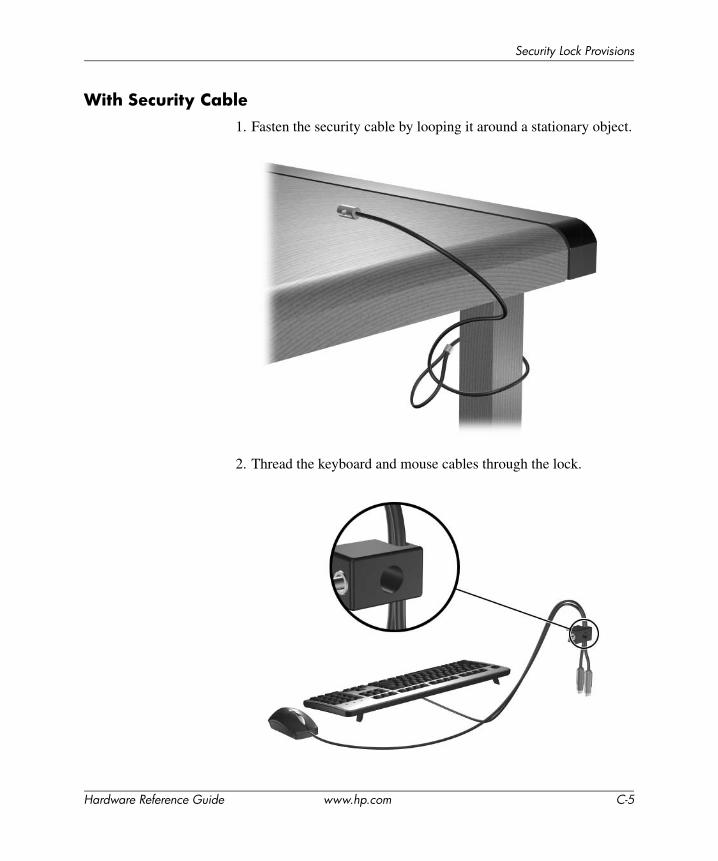
With Security Cable1. Fasten the security cable by looping it around a stationary object.
2. Thread the keyboard and mouse cables through the lock.
Hardware Reference Guide www.hp.com C-5
Security Lock Provisions
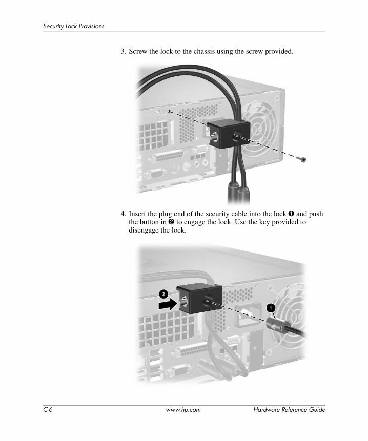
3. Screw the lock to the chassis using the screw provided.
4. Insert the plug end of the security cable into the lock 1 and push the button in 2 to engage the lock. Use the key provided to disengage the lock.
C-6 www.hp.com Hardware Reference Guide
DElectrostatic Discharge
A discharge of static electricity from a finger or other conductor may damage system boards or other static-sensitive devices. This type of damage may reduce the life expectancy of the device.
Preventing Electrostatic DamageTo prevent electrostatic damage, observe the following precautions:
■ Avoid hand contact by transporting and storing products in static-safe containers.
■ Keep electrostatic-sensitive parts in their containers until they arrive at static-free workstations.
■ Place parts on a grounded surface before removing them from their containers.
■ Avoid touching pins, leads, or circuitry.
■ Always be properly grounded when touching a static-sensitive component or assembly.
Grounding MethodsThere are several methods for grounding. Use one or more of the following methods when handling or installing electrostatic-sensitive parts:
■ Use a wrist strap connected by a ground cord to a grounded workstation or computer chassis. Wrist straps are flexible straps with a minimum of 1 megohm +/- 10 percent resistance in the ground cords. To provide proper ground, wear the strap snug against the skin.
Hardware Reference Guide www.hp.com D-1
Electrostatic Discharge
■ Use heelstraps, toestraps, or bootstraps at standing workstations. Wear the straps on both feet when standing on conductive floors or dissipating floor mats.
■ Use conductive field service tools.
■ Use a portable field service kit with a folding static-dissipating work mat.
If you do not have any of the suggested equipment for proper grounding, contact an HP authorized dealer, reseller, or service provider.
✎ For more information on static electricity, contact an HP authorized dealer, reseller, or service provider.
D-2 www.hp.com Hardware Reference Guide
EComputer Operating Guidelines,
Routine Care and Shipping Preparation
Computer Operating Guidelines and Routine CareFollow these guidelines to properly set up and care for the computer and monitor:
■ Keep the computer away from excessive moisture, direct sunlight, and extremes of heat and cold. For information about the recommended temperature and humidity ranges for the computer, refer to Appendix A, “Specifications” in this guide.
■ Operate the computer on a sturdy, level surface. Leave a 10.2-cm (4-inch) clearance on all vented sides of the computer and above the monitor to permit the required airflow.
■ Never restrict the airflow into the computer by blocking any vents or air intakes. Do not place the keyboard, with the keyboard feet down, directly against the front of the desktop unit as this also restricts airflow.
■ Never operate the computer with the cover or side panel removed.
■ Do not stack computers on top of each other or place computers so near each other that they are subject to each other’s re-circulated or preheated air.
■ If the computer is to be operated within a separate enclosure, intake and exhaust ventilation must be provided on the enclosure, and the same operating guidelines listed above will still apply.
■ Keep liquids away from the computer and keyboard.
■ Never cover the ventilation slots on the monitor with any type of material.
■ Install or enable power management functions of the operating system or other software, including sleep states.
Hardware Reference Guide www.hp.com E-1
Computer Operating Guidelines, Routine Care and Shipping Preparation
■ Turn off the computer before you do either of the following:
❏ Wipe the exterior of the computer with a soft, damp cloth as needed. Using cleaning products may discolor or damage the finish.
❏ Occasionally clean the air vents on all vented sides of the computer. Lint, dust, and other foreign matter can block the vents and limit the airflow.
Optical Drive PrecautionsBe sure to observe the following guidelines while operating or cleaning the optical drive.
Operation■ Do not move the drive during operation. This may cause it to
malfunction during reading.
■ Avoid exposing the drive to sudden changes in temperature, as condensation may form inside the unit. If the temperature suddenly changes while the drive is on, wait at least one hour before you turn off the power. If you operate the unit immediately, it may malfunction while reading.
■ Avoid placing the drive in a location that is subject to high humidity, extreme temperatures, mechanical vibration, or direct sunlight.
Cleaning■ Clean the panel and controls with a soft, dry cloth or a soft cloth
lightly moistened with a mild detergent solution. Never spray cleaning fluids directly on the unit.
■ Avoid using any type of solvent, such as alcohol or benzene, which may damage the finish.
SafetyIf any object or liquid falls into the drive, immediately unplug the computer and have it checked by an authorized HP service provider.
E-2 www.hp.com Hardware Reference Guide

Computer Operating Guidelines, Routine Care and Shipping Preparation
Shipping PreparationFollow these suggestions when preparing to ship the computer:
1. Back up the hard drive files on PD discs, tape cartridges, CDs, or diskettes. Be sure that the backup media is not exposed to electrical or magnetic impulses while stored or in transit.
✎ The hard drive locks automatically when the system power is turned off.
2. Remove and store any program diskettes from the diskette drives.
3. Insert a blank diskette into the diskette drive to protect the drive while in transit. Do not use a diskette on which you have stored or plan to store data.
4. Turn off the computer and external devices.
5. Disconnect the power cord from the electrical outlet, then from the computer.
6. Disconnect the system components and external devices from their power sources, then from the computer.
✎ Ensure that all boards are seated properly and secured in the board slots before shipping the computer.
7. Pack the system components and external devices in their original packing boxes or similar packaging with sufficient packing material to protect them.
✎ For environmental nonoperating ranges, see Appendix A, “Specifications” in this guide.
Hardware Reference Guide www.hp.com E-3
Index
Aapplication key 1–4audio connectors 1–2, 1–3, 2–15
Bbattery replacement B–1bezel
installing 2–43part numbers 2–20, 2–39, 2–43removing 2–42
Ccable lock, installing C–1chassis clamp lock, installing C–3components
front panel 1–2rear panel 1–3
computer coverremoving 2–5replacing 2–6Smart Cover Lock 2–3
computer operating guidelines E–1computer specifications A–1
Ddesktop dimensions A–1DIMMs
See memorydiskette drive
activity light 1–2eject button 1–2removing 2–21
drivebezel 2–20, 2–39, 2–42installation guidelines 2–19locations 2–20
Eelectrostatic discharge, preventing damage
D–1expansion card
installing 2–13optional riser 2–13PCI 2–13PCI Express 2–13, 2–17slot locations 2–13
expansion slot cover, removing 2–14
FFailSafe Key
ordering 2–3using 2–3
front panel components 1–2
Gguide screws 2–19, 2–28, 2–40guidelines
battery replacement B–1computer operating E–1drive installation 2–19optical drive E–2servicing the computer 2–1shipping preparation E–3
Hardware Reference Guide www.hp.com Index-1
Index
Hhard drive
activity light 1–2installing in 3.5-inch bay 2–39removing 2–38replacing 2–33restoring 2–39SATA connectors 2–19
headphone connector 1–2
Iinstallation guidelines 2–19installing
battery B–1cable lock C–1chassis clamp lock C–3diskette drive or hard drive in 3.5-inch bay
2–39expansion card 2–13guide screws 2–28hard drive 2–40, 2–41memory 2–7optical drive 2–28padlock C–2
Kkeyboard
components 1–4connector 1–3
Lline-out connector 1–3locks
cable lock C–1chassis clamp lock C–3padlock C–2Smart Cover Lock 2–3
Mmemory
Asymetric mode 2–8capacity 2–7, 2–8, 2–11identifying modules 2–11identifying sockets 2–9installing 2–7Interleaved mode 2–8populating sockets 2–8single channel mode 2–8specifications 2–7
microphone connector 1–2monitor, connecting 1–3mouse
connector 1–3special functions 1–5
Ooptical drive
activity light 1–2cleaning E–2connecting cables 2–31eject button 1–2guide screws 2–28guidelines E–2installing 2–28location 1–2precautions E–2removing 2–21
Ppadlock, installing C–2Parallel ATA devices 2–19parallel connector 1–3PCI card
See expansion cardpower
button 1–2cord connector 1–3indicator light 1–2
power supply 2–36, A–2
Index-2 www.hp.com Hardware Reference Guide
Index
Rrear panel components 1–3removing
bezel 2–42computer cover 2–5diskette drive 2–21expansion slot cover 2–14hard drive 2–38optical drive 2–21PCI Express expansion card 2–17Smart Cover Lock 2–4
RJ-45 connector 1–3
SSATA
controllers 2–19installing hard drive 2–33, 2–39
security locks C–1serial connector 1–3serial number location 1–6shipping preparation E–3
Smart CoverFailSafe key 2–3lock 2–3removing lock 2–4
specificationscomputer A–1memory 2–7
status lights 1–4support telephone numbers 2–3
UUSB ports
front panel 1–2rear panel 1–3
Vventilation guidelines E–1
WWindows Logo key
functions 1–5locations 1–4
Hardware Reference Guide www.hp.com Index-3