Embed Size (px)
Citation preview

1
Hardware Information Sheet
Issue: A (Preliminary)

2
Contents
Table of Figures ........................................................................................................................ 2
Scope ........................................................................................................................................ 3
Introduction .............................................................................................................................. 3
CoreBASIC ................................................................................................................................ 4
Electrical Specification ........................................................................................................... 5
Power ..................................................................................................................................... 5
Pin Specification................................................................................................................... 5
Digital I/O .......................................................................................................................... 5
Analogue Inputs ............................................................................................................... 6
Jumper Configuration ......................................................................................................... 6
User LED Information ............................................................................................................ 7
Ethernet ................................................................................................................................. 7
USB.......................................................................................................................................... 7
microSD ................................................................................................................................. 8
SPI Memory Expansion ......................................................................................................... 8
I2C Expansion ....................................................................................................................... 8
JTAG ....................................................................................................................................... 9
SolderCore Pin Functions .................................................................................................... 9
Programming SolderCore ..................................................................................................... 11
Mechanical Details ............................................................................................................... 12
Appendix A – Flashing SolderCore ...................................................................................... 13
Appendix B - Supported Shields .......................................................................................... 17
Table of Figures
Figure 1 SolderCore Features ................................................................................................. 4
Figure 2 Connecting to SolderCore using Ethernet ............................................................ 4
Figure 3 SolderCore Jumper Configuration ......................................................................... 6
Figure 4 SolderCore PCB Outline ......................................................................................... 12

3
Scope
This document is intended to familiarize the reader with the basic features of the
SolderCore development platform. This document is not intended as complete users.
For more detailed information on using the SolderCore please visit the website.
Introduction
SolderCore is complete development platform consisting of an Arduino-shaped
microcontroller “CPU” board with a new and exciting software development
environment called CoreBASIC. SolderCore features a Cortex-M3 processor capable
of running at clock speeds of up to 80 MHz and provides a compact, flexible solution
for rapid product development. SolderCore is compatible with a large range of third
party plug-in PCBs to expand its capabilities.
Hardware Features:
1) 80 MHz ARM Cortex-M3 processor
2) 512kB of flash.
3) 96kB of RAM.
4) 20 user-programmable I/O pins + 6 power pins. Pins can be programmed to
perform alternative functions including I2C, SPI, UART, PWM, CCP, ADC, QEI
and CAN
5) 10/100 Mbit Ethernet port.
6) Micro-AB USB On-The-Go connector.
7) Spring-loaded microSD card holder.
8) 2.2mm barrel jack for power supply. 6 – 9V. Reverse polarity protected.
9) Standard Cortex 10-pin JTAG connector.
10) Two power indicator LEDs.
11) Five user programmable LEDs
12) Reset button
4
Figure 1 SolderCore Features
CoreBASIC
SolderCore is shipped with a powerful and fun development environment called
CoreBASIC. CoreBASIC allows users to write complex applications that can utilize the
devices hardware in very little time. Users access CoreBASIC using a web browser or
over Telnet by connecting a PC to the device using the Ethernet port, CoreBASIC will
work with any operating system that has a web browser or Telnet capability.
Figure 2 Connecting to SolderCore using Ethernet
CoreBASIC is a rich language that supports the following features:
HTTP, Telnet, SMTP, DHCP,FTP, complex numbers, matrix mathematics, quaternions,
trigonometry, logarithmic, FAT, string manipulation, FIR/IIR Filtering, Analog/Digital IO,
PWM, I2C, UART, MIDI support, CAN, USB and direct shield support
These features and more can be utilized using the CoreBASIC language. CoreBASIC
programs can be downloaded from the SolderCore website directly to the
SolderCore, where you can edit, save and run the program. The SolderCore supports
in excess of 60 shields and plug-in modules (Appendix B - Supported Shields) from
third party vendors, such as Sparkfun, Arduino, Watterott electronic, Adafuit
Industries, and more. To keep up with ever-growing list of new hardware, SolderCore
can be updated over the web with the latest code using a single command.

5
Electrical Specification
Power
The SolderCore can be powered from the 2.2mm barrel jack connector or the
Micro-AB USB connector.
The voltage applied to the barrel jack should be between 6V and 9V. The inner pin
of the barrel jack is the positive connection.
SolderCore has two onboard regulators for generating 3.3V and 5.0V. The power
rails are routed to the power connector for powering external PCBs. When using
SolderCore with external modules supplied from the power pins, care should be
taken to consume no more than 800mA from the power supply.
When power is supplied via the USB connector, the 5V rail will be approximately 4.7V
due a protection diode voltage drop.
Pin Specification
Digital I/O
Pins D0–D13 and A0–A5 when configured as digital I/O are 5V tolerant. When A0 to
A5 are set as analog inputs they are not 5V tolerant and no more than 3.3V should
be applied to them.
Every I/O pin can be further configured (in Software) to support:
Weak pull-up (50K – 110k) or pull-down (55k – 180K) resistors
Flexible drive current. (2mA, 4mA and 8mA)
Slew rate control (8 mA only)
Open drain.
Parameter Parameter Name Min Nom Max Unit
VIH High level Input
Voltage
2.0 0 5.0 V
VIL Low-level input
voltage
-0.3 - 1.3 V
VOH High level output
voltage
2.4 - - V
VOL Low-level output
voltage
- - 0.4 V
Table 1. Digital I/O Specification

6
Analogue Inputs
A0–A5 can be configured as ADC inputs. A4 and A5 are shared with SCL/SDA and
thus JP1 and JP3 must be set accordingly (see section
Jumper Configuration). The analog inputs can sample at a maximum frequency of
1MHz at a resolution of 10 bits. Table 2 details the ADC specifications.
Parameter Parameter Name Min Nom Max Unit
VADCIN Maximum single-
ended, full-scale
analog input voltage
using internal reference
- - 3.3 V
Maximum single
ended, full scale
analog input voltage
using external
reference
- - VREFA V
Minimum single-ended,
full scale analog input
voltage
0 - - V
Maximum differential,
full scale analog input
voltage using internal
reference
VREFA/2 V
Minimum differential,
full-scale analog input
voltage.
0 V
N Resolution 10 Bits
tADCCONV Conversion time. 1 uS
Table 2 ADC Specification
Jumper Configuration
There are three (3 way) jumpers on the SolderCore which can be used to tailor
device operation. Figure 3 shows the position and default configuration for each the
solder jumpers. Each jumper consists of three pads. The center pad (pad 2) should
be connected to either pad 1 or pad 3 (not both) using a solder bridge.
Figure 3 SolderCore Jumper Configuration

7
JP1 and JP3 configure the device for either I2C mode or Analog mode. By default
the SolderCore is configured for I2C.
JP4 is used to select the reference voltage for microcontrollers ADC. By default the
reference voltage is set by the A pin of J3. However, the reference voltage can be
tied to the 3.3V rail if it is deemed more convenient by modifying the solder jumper;
in this mode the REF pin is disconnected.
User LED Information
There are 5 LEDs located on the SolderCore that can be activated through code by
the user. Two of these LEDs are located within the RJ45 connector.
Table 3 details the LED connections to the microprocessor
LED Description LM3S Pin
1 UL – User-configurable LED –
Green
PC5
2 IDL – User configurable LED –
Green
PE7
3 CS – microSD Chip Select LED –
Red
PJ4
4 RJ45 LED – Yellow PF2
5 RJ45 LED – Green PF3
Table 3 LED Pin Configuration
Two LEDs indicate the 3.3V and 5.0 V rail are operating correctly. When power is
applied, both of these should light.
The RJ45 LEDs can be configured to be under program control or to display the
status and activity on the Ethernet link. By default, the RJ45 LEDs display Ethernet-
related information.
Ethernet
SolderCore provides an RJ45 connector with integrated magnetic for connection to
10/100 Mbit Ethernet networks. The Ethernet connector has two internal LEDs that
can be configured to provide activity information on the network. Refer to Table 3
for LED connection information. Every SolderCore will be pre-programmed with a
MAC address. The MAC address is stored within USER configuration registers. A label
is appended to the underside of the SolderCore with the device MAC address.
USB
SolderCore provides a USB micro AB connector for support of the USB otg protocol.
SolderCore can be software configured to act as a USB host or slave. In host mode
SolderCore can sources up to 500mA at 5V to power external peripherals.

8
microSD
SolderCore provides a microSD holder. Programs are able to read and write data to
a micro SD card.
An internal SPI bus is used to communicate with the card which is separate from the
hardware SPI bus routed to the user-accessible signals on the headers. The internal
SPI bus is shared with the two SOIC-8 memory devices that can be populated on the
underside of the SolderCore. Table 4 details the pins used on the microcontroller to
communicate with the microSD card.
Signal
Name
LM3S Pin
SCK PH4
MISO PF4
MOSI PF5
CSSD PG7
Table 4 LM3S to microSD pin information.
SPI Memory Expansion
The SolderCore has two SOIC-8 sites on the underside of the PCB which you can
populate with compatible SPI-based memory devices. CoreBASIC does not support
these at the current time, but we intend to support them in a future release. The SPI
bus used for data transfer is common to that used by the microSD card bar the IC
chip selects.
I2C Expansion
The SolderCore has an additional I2C header located adjacent to the two user LEDs.
This I2C bus is currently unused and CoreBASIC does not support it. You can,
however, attach additional I2C devices to this bus along with I2C pull-up resistors
and program them in your own C-based applications.

9
JTAG
The SolderCore provides a 10-way Cortex JTAG connector for programming and
debugging the on-board microcontroller.
JTAG Signal
Name
Connector Pin
Number
VREF (3V3) 1
TMS 2
GND 3, 5, 9
TCK 4
TDO 6
TDI 8
RST 10
Table 5 JTAG Connector Pin out
Holding TCK low during a power up will place the SolderCore into Boot mode. See
Appendix A – Flashing SolderCore for more information.
SolderCore Pin Functions
The SolderCore general I/O pins are multifunctional; pins can be configured, using
software, to perform alternative functions. These alternative functions include I2C,
SPI, ADC, I2S, CAN and PWM. Table 6 details the SolderCore pin allocation and
function. Pin functionality of the SolderCore is similar to that of the Arduino module.

10
J1 LM3S Arduino GPIO I2C SPI CAN I2S QEI PWM/CCP Analog UART
1 10 D0(Rx) PD0 - - Rx0 RXSCK0 IDX0 - P0 CC6 - - - AIN15 Rx2 Rx1 CTS1
2 6 D1(Tx) PE4 - - - TXWS0 - - CC3 CC2 - - - AIN3 Tx2 - -
3 5 D2 PE5 - - - TXSD0 - - CC5 - - - - AIN2 - - -
4 2 D3 (PWM) PE6 - - - - - - P4 - - - - AIN1 CTS1 - -
5 18 D4 PG1 SDA1 - - - - - P1 P5 - - - - Tx2 - -
6 47 D5 (PWM) PF0 - - Rx1 TXSD0 PhB0 - P0 - - - - - DSR1 - -
7 11 D6 (PWM) PD1 - - Tx0 RXWS0 PhA0 PhB1 P1 CC7 - - CC2 AIN14 Tx2 Tx1 DCD1
8 61 D7 PF1 - - Tx1 TXMCLK0 IDX1 - P1 CC3 - - - - RTS2 - -
J2 LM3S Arduino
1 95* A5 / D19
(SCL) PB2 SCL0 - - - IDX0 - CC3 CC0 - - - - - - -
2 96* A4 / D18
(SDA) PB3 SDA0 - - - - - - - - - - - - - -
3 97 A3 / D17 PD4 - - - RXSD0 - - CC0 CC3 - - - AIN7 RI2 - -
4 98 A2 / D16 PD5 - - - RXMCLK0 - - CCP2 CC4 - - - AIN6 Rx2 - -
5 99 A1 / D15 PD6 - - - TXSCK0 - - - - - - - AIN5 Tx2 - -
6 100 A0 / D14 PD7 - - - TXWS0 IDX0 - CC1 - - - - AIN4 DTR1 - -
J3 LM3 Arduino
1 22 D8 PC7 - - - - PhB0 - CC0 CC4 - - - - Tx1 - -
2 25 D9(PWM) PC4 - - - - PhA0 - P6 CC1 CC2 CC4 CC5 - - - -
3 12 D10 (PWM) PD2 - - - - - - P2 CC6 - - CC5 AIN13 Rx1 - -
4 31 D11 (MOSI,
PWM) PA5 - Tx0 Tx0 TXWS0 - - P7 - - - - - - - -
5 30 D12 (MISO) PA4 - Rx0 Rx0 TXSCK0 - - P6 - - - - - - - -
6 28 D13 (SCK) PA2 - Clk0 - RXSD 0 - - P4 - - - - - - - -
7 GND GND - - - - - - - - - - - - - - - -
8 AREF* AREF PB6 - - - TXSCK IDX0 - CC1 CC5 CC7 - - VREFA - - -
Table 6 SolderCore Pin Information
*Selectable via Solder Jumper
11
Programming SolderCore
SolderCore is delivered preprogrammed with CoreBASIC. Users programming
CoreBASIC only require a PC with Ethernet & USB connecion, no other hardware is
required. CoreBASIC is the quickest and simplest way to get going with SolderCore.
For further information on CoreBASIC please visit the SolderCore WebSite.
eLua (embedded Lua) has also been ported to SolderCore. eLua is an open source
interpreted language, for more information on eLua, please visit the eLua website.
Although SolderCore is preloaded, with CoreBASIC, it is a simple task to load new
firmware without the need for any other hardware. SolderCore has an Ethernet
booloader that works with the Texas Instruments LMFLASH tool, freely available from
TI.
To re-flash a SolderCore with new firmware follow the procedures in Appendix A.

12
Mechanical Details
The SolderCore PCB has the same form factor as the popular Arduino module.
Figure 4 SolderCore PCB Outline

13
Appendix A – Flashing SolderCore
To re flash the SolderCore follow the instructions below. (Note: CoreBASIC is not
available in a binary format. Once erased, CoreBASIC can only be reprogrammed
at Hot Solder UK ltd or Rowley Associates).
1) Download LMFlash tool from Texas Instruments.
2) Configure the Ethernet port on the PC to use a fixed address of 192.168.1.1.
a. Open the control panel.
b. Select Network and Sharing
c. Select Change Adapter Settings
d. Right click and select properties on the local area connection that is
going to be used for programming SolderCore.
e. Select Internet Protocol Version 4 (TCP/IPv4) and select properties.

14
f. Select Use the Following IP address: and set the IP address to
192.168.1.1 and the Subnet mask to 255.255.255.0
g. Click Ok
3) Connect SolderCore to a PC using the Ethernet connector. Make sure
SolderCore is connected to the Ethernet port configured with a fixed IP
address
4) Power up the SolderCore.
5) Place SolderCore into Boot mode by holding pin 4 of J7 (JTAG connector) low
and pressing the reset button.
6) Run the LMFlash tool and select the configuration tab.
7) In the Quick Set pull down list, select “Manual Configuration”.
8) Select “Ethernet in the Interface drop down menu.
9) Type IP client address to 192.168.1.2. (This is the address SolderCore is given
during the programming sequence)
10) Type in the devices MAC address. The MAC address can be found on a label
on the underside SolderCore.

15
11) Select the correct Ethernet Adapter from the drop down list.
12) Select the Program tab and browse to the location of the binary file to be
programmed to SolderCore.
13) Click on the Program button and wait for the programmer to finish.
14) Reset the SolderCore and the new binary file should be running.
15) Browse to the binary file that is to be programmed to the SolderCore
hardware.
16
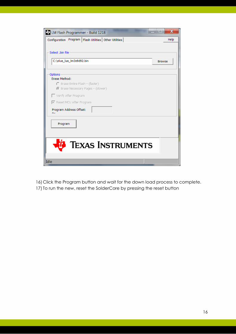
16) Click the Program button and wait for the down load process to complete.
17) To run the new, reset the SolderCore by pressing the reset button

17
Appendix B - Supported Shields
1. 4D-SYSTEMS-4DISPLAY-SHIELD Shield
2. 4D-SYSTEMS-MICROCAM
3. ADAFRUIT-TFT-TOUCH-SHIELD Shield
4. ANALOG-DEVICES-ADXL345 SExI
5. ARDUINO-MOTOR-CONTROL-SHIELD Shield
6. ASAHI-KASEI-AK8975
7. BOSCH-SENSORTEC-BMP085 SExI
8. CIRCUITS@HOME-USB-HOST-SHIELD Shield
9. CIRCUITS@HOME-USB-HOST-SHIELD Shield
10. CORE-WSN SExI
11. EXCAMERA-GAMEDUINO Shield
12. FREESCALE-MAG3110
13. FREESCALE-MMA7660FC
14. FREESCALE-MMA8451Q
15. GRAVITECH-7SEG-SHIELD Shield
16. HONEYWELL-HMC5883L
17. HONEYWELL-HMC6352
18. INTERSIL-ISL29023 SExI
19. INVENSENSE-IDG3200 SExI
20. INVENSENSE-IDG3200 SExI
21. INVENSENSE-MPU-6050 SExI
22. JEE-LABS-LCD-PLUG Plug
23. JIMMIE-RODGERS-LOL-SHIELD Shield
24. LIQUIDWARE-INPUTSHIELD:MODE-A Shield
25. MAXIM-DS1340 Plug
26. NINTENDO-CLASSIC-CONTROLLER SExI
27. NINTENDO-NUNCHUK-CONTROLLER SExI
28. NUELECTRONICS-3310-LCD-SHIELD Shield
29. NUELECTRONICS-LCD-KEYPAD-SHIELD Shield
30. OLIMEX-MOD-MOKIA6610
31. PS2-KEYBOARD
32. ROWLEY-OLED-SHIELD
33. ROWLEY-QWHEEL-SHIELD
34. ROWLEY-UVGA-SHIELD
35. SEEED-STUDIO-OLED-128x64-BRICK Twig Brick
36. SEEED-STUDIO-OLED-96x16-BRICK Brick
37. SEEED-STUDIO-OLED-96x96-TWIG Twig
38. SEEED-STUDIO-SD-CARD-SHIELD Brick
39. SEEED-STUDIO-TFT-TOUCH-SHIELD Shield
40. SOLDERCORE-ARCADE-SHIELD Shield
41. SOLDERCORE-ARCADE-SHIELD Shield
42. SOLDERCORE-LCD-SHIELD Shield
43. SOLDERCORE-MOTOR-SHIELD Shield
44. SOLDERCORE-SENSECORE Shield
45. SOLDERCORE-SERVO-SHIELD Shield
46. SPARKFUN-ARDUMOTO Shield

18
47. SPARKFUN-BUTTONPAD
48. SPARKFUN-COLOR-LCD-SHIELD Shield
49. SPARKFUN-DANGER-SHIELD Shield
50. SPARKFUN-EL-ESCUDO Shield
51. SPARKFUN-JOYSTICK-SHIELD Shield
52. SPARKFUN-MICROSD-SHIELD Shield
53. SPARKFUN-MIDI-BREAKOUT Shield
54. SPARKFUN-MIDI-SHIELD Shield
55. SPARKFUN-RADIO-SHIELD Shield
56. SPARKFUN-RINGCODER-BREAKOUT
57. SPARKFUN-SPECTRUM-SHIELD Shield
58. SPARKFUN-TOUCH-SHIELD Shield
59. SPARKFUN-USB-HOST-SHIELD Shield
60. SPARKFUN-USB-HOST-SHIELD-SKU-9628 Shield
61. SPARKFUN-VOICEBOX-SHIELD Shield
62. SPARKFUN-WIFLY-SHIELD Shield
63. SPARKFUN-XBEE-SHIELD Shield
64. STMICROELECTRONICS-LIS302DL
65. TAOS-TSL2561
66. THINGM-BLINKM-BREAKOUT Breakout
67. U-BLOX-NEO-6
68. WATTEROTT-MSD-SHIELD Shield
69. WATTEROTT-S65-SHIELD Shield