Embed Size (px)
Citation preview
September 2013 Altera Corporation
WP-01208-1.0
© 2013 Altera Corporation. AlNIOS, QUARTUS and STRATTrademark Office and in othetheir respective holders as desproducts to current specificatioproducts and services at any tiof any information, product, oadvised to obtain the latest verfor products or services.
101 Innovation DriveSan Jose, CA 95134www.altera.com
Hardware in the Loop from theMATLAB/Simulink Environment
White Paper
This white paper describes the tools, design flow, and verification of systems using Altera® FPGAs. It discusses the techniques of software simulation and hardware testing, and the challenges associated with them. This paper also describes the advantages of using the Hardware in the Loop (HIL) tool, which is part of Altera’s software tools, to simplify software simulation and hardware testing in a variety of applications. To implement the HIL approach, you must create a communication link between the host development platform and the target deployment platform. The host-target communication infrastructure, called the MATLAB API, is provided by Altera as part of its system-in-the-loop solution. The communication link is established using a simple application programming interface (API) that is accessible from the MATLAB/Simulink tools by MathWorks. The MATLAB API protocol allows you to perform interactive communication with the target FPGA from the host computer.
IntroductionToday there are various methodologies for developing digital systems. These methodologies include the processes for tuning, validating, and verifying systems. Every industry can develop their own de-facto approaches.
System development testing is mainly done using two approaches. First, the functionality and performance of the system is observed and tuned using software simulation tools. The level of confidence that is obtained from the software simulation is application-specific, and depends on the availability and accuracy of the system models, testbench coverage, and duration of the executed tests. Second, the design is deployed on a target platform to verify the functionality and measure the performance under more realistic conditions. This approach is also known as hardware testing.
In this paper, we examine the HIL and rapid prototyping methodologies as complementary approaches to software simulation and hardware testing. The examples in this white paper focus mainly on motor control designs, although these approaches are also applicable in other areas.
l rights reserved. ALTERA, ARRIA, CYCLONE, ENPIRION, HARDCOPY, MAX, MEGACORE, IX words and logos are trademarks of Altera Corporation and registered in the U.S. Patent and r countries. All other words and logos identified as trademarks or service marks are the property of cribed at www.altera.com/common/legal.html. Altera warrants performance of its semiconductor ns in accordance with Altera's standard warranty, but reserves the right to make changes to any
me without notice. Altera assumes no responsibility or liability arising out of the application or use r service described herein except as expressly agreed to in writing by Altera. Altera customers are sion of device specifications before relying on any published information and before placing orders
Feedback Subscribe
ISO 9001:2008 Registered

Page 2 System Verification Using Software Simulation
System Verification Using Software SimulationSoftware simulation offers a flexible approach to system verification. It allows you to run through a variety of system behavior and scenarios. However, the testbench coverage on a real system is limited due to the following reasons:
■ System design runtime can be extremely long when simulations are performed on a reasonably big system. For example, in electro-mechanical systems, the time constants of a mechanical system can be measured in seconds while the digital computation rate is measured in nanoseconds.
■ Significant inaccuracies might occur due to the uncertainties of a system model. The system model might not be known or completely characterized. It might contain different non-linear components and environment disturbances that are very difficult to measure and characterize.
■ A complementary verification flow might still be needed to verify the design to obtain reliability certification. This is especially true with modern flows that involve high-level synthesis tools.
System Verification Using Hardware Testing Hardware testing allows you to deploy the design on target and observe the performance of the design under real-life conditions. However, this approach, too, has its own challenges, as highlighted below:
■ Usually only the desired scenario is tested. It is difficult to observe the system behavior in “something went wrong” scenarios because the complete hardware test involves external system components that are pre-defined as well. Other system components do not always allow flexibility in the stimulus that can be applied to the design under test (DUT).
■ The availability of a hardware platform is also a concern. The final implementation platform is not always available during the initial design phases.
■ The cost of verification is a direct result of final hardware availability. The test time on a hardware platform can be expensive, so it may be shared between multiple users, departments, or divisions. However, this method might eventually cause less verification coverage.
■ Safety is another critical aspect of hardware testing, especially during the initial phases of the design when there are uncertainties in multiple system components. Hardware testing on multiple system components puts significant burden on designers as it requires careful test planning and damage mitigation.
System Verification Using Hardware in the Loop and Rapid PrototypingThe HIL and rapid prototyping methodologies provide an intermediate level of system verification between software simulation and hardware testing. Both methodologies are hybrids of software and hardware approaches, and inherit benefits from both. The main difference between the two is the location of boundaries that separate the software and hardware. You do not have to choose between the two methods; you can apply both methods in an incremental way according to a given situation.
September 2013 Altera Corporation Hardware in the Loop from the MATLAB/Simulink Environment
System Verification Using Hardware in the Loop and Rapid Prototyping Page 3
In the HIL approach, the design is deployed to hardware and runs in real time. However, the surrounding components are simulated in a software environment. This might include stimulus generators, sensors, observers, and mechanical actuators. Such methodology allows software flexibility with real-world accuracy and hardware speed execution. One must note that the system-level accuracy is still limited to the system model applied in the software. Thus, the next step is to include real hardware components gradually into the system verification testbench. Such gradual process has much more control over the integration process, so system tuning and validation can be obtained easily and safely.
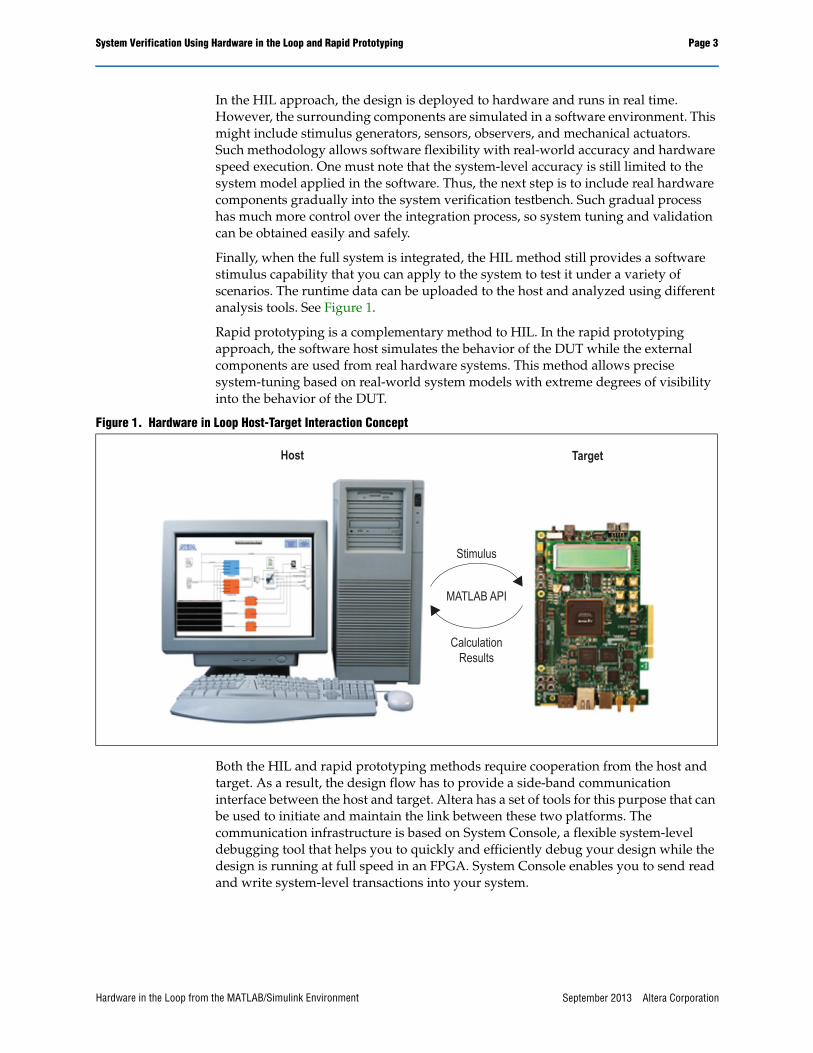
Finally, when the full system is integrated, the HIL method still provides a software stimulus capability that you can apply to the system to test it under a variety of scenarios. The runtime data can be uploaded to the host and analyzed using different analysis tools. See Figure 1.
Rapid prototyping is a complementary method to HIL. In the rapid prototyping approach, the software host simulates the behavior of the DUT while the external components are used from real hardware systems. This method allows precise system-tuning based on real-world system models with extreme degrees of visibility into the behavior of the DUT.
Both the HIL and rapid prototyping methods require cooperation from the host and target. As a result, the design flow has to provide a side-band communication interface between the host and target. Altera has a set of tools for this purpose that can be used to initiate and maintain the link between these two platforms. The communication infrastructure is based on System Console, a flexible system-level debugging tool that helps you to quickly and efficiently debug your design while the design is running at full speed in an FPGA. System Console enables you to send read and write system-level transactions into your system.
Figure 1. Hardware in Loop Host-Target Interaction Concept
Host Target
Stimulus
MATLAB API
Calculation
Results
September 2013 Altera CorporationHardware in the Loop from the MATLAB/Simulink Environment

Page 4 MATLAB API
MATLAB APIMATLAB/Simulink is a high-level language and interactive environment from MathWorks that is popular among system and algorithm designers. It can be used in a wide variety of applications and research topics. To accommodate the developers’ need to interface their designs with Altera’s FPGA, Altera created an API that can be called from the MATLAB environment to send and receive data to or from an FPGA. The API is a simple set of commands which allows real-time interaction with the FPGA design running on your target platform. The interaction is done using memory-mapped transactions initiated from the MATLAB environment. These transactions are captured by a dedicated Avalon® Memory-Mapped (Avalon-MM) Master interface connected to an Avalon-MM Slave interface inside your design, and compiled into an FPGA. Example 1 shows an example MATLAB API script.
f For further information about the Avalon-MM interfaces in the System Console, please refer to the Avalon Interface Specifications.
The MATLAB API can be used in multiple tasks while designing, evaluating, and verifying designs. It can be used to configure and tune an FPGA design parameter in runtime similar to tuning data pipe gains and modifying filter parameters. It can also be used to monitor different statuses by reading specific registers in runtime. The most powerful capability of the MATLAB API can be seen in the HIL approach. It allows you to generate complex stimulus datasets on the host PC and download to the FPGA target in real time. This is convenient because it is rarely possible to create such a flexible and sophisticated stimulus on a target platform with minimal programming effort.
Example 1. MATLAB API Script Example
SystemConsole.refreshMasters; %Investigate available targets
M = SystemConsole.openMaster(1); %Creates connection with FPGA target
%%%%%%%% User Application %%%%%%%%%%%%. . . .M.write('uint32',write_address,data); %Send data to FPGA target. . . . data = M.read('uint32',read_address,size); %Read data from FPGA target. . . .%%%%%%%%%%%%%%%%%%%%%%%%%%%%%%%%%%%%%%
M.close; %Terminates connection to FPGA target
September 2013 Altera Corporation Hardware in the Loop from the MATLAB/Simulink Environment
MATLAB API Page 5
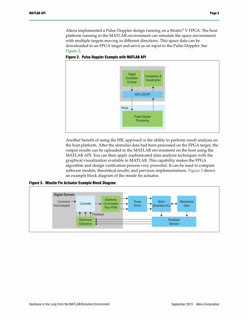
Altera implemented a Pulse-Doppler design running on a Stratix® V FPGA. The host platform running in the MATLAB environment can simulate the space environment with multiple targets moving in different directions. This space data can be downloaded to an FPGA target and serve as an input to the Pulse-Doppler. See Figure 2.
Another benefit of using the HIL approach is the ability to perform result analysis on the host platform. After the stimulus data had been processed on the FPGA target, the output results can be uploaded to the MATLAB environment on the host using the MATLAB API. You can then apply sophisticated data analysis techniques with the graphical visualization available in MATLAB. This capability makes the FPGA algorithm and design verification process very powerful. It can be used to compare software models, theoretical results, and previous implementations. Figure 3 shows an example block diagram of the missle fin actuator.
Figure 2. Pulse Doppler Example with MATLAB API
Target
Emulation
& Noise
Comparison &
Visualization
MATLAB API
Pulse Doppler
Processing
FPGA
Figure 3. Missile Fin Actuator Example Block Diagram
Controller
Electronic
Commutator
Plus PWM
Observers/
Estimators
Power
Driver
Motor
(Brushless DC)
Mechanical
Gear
Digital Domain
Command
from Autopilot
Feedback
Sensors
Feedback
September 2013 Altera CorporationHardware in the Loop from the MATLAB/Simulink Environment
Page 6 HIL with Simulink Flow
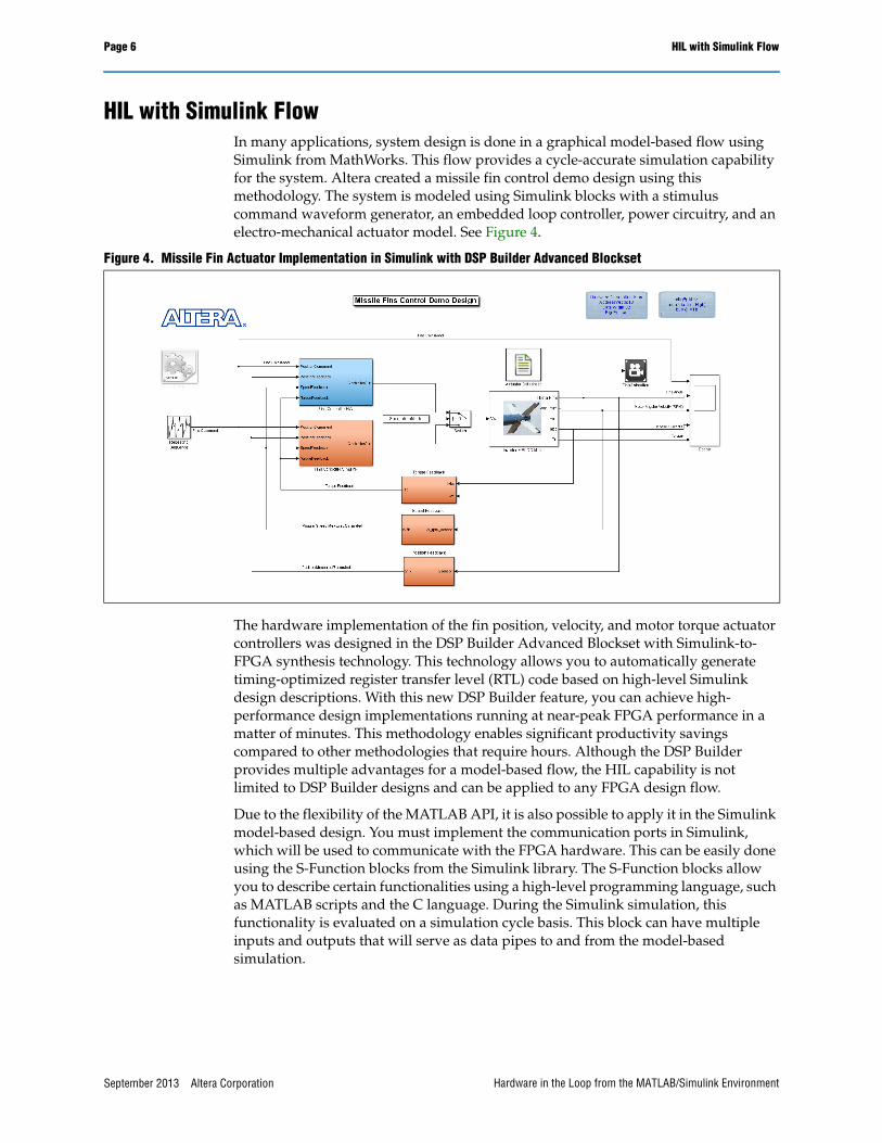
HIL with Simulink FlowIn many applications, system design is done in a graphical model-based flow using Simulink from MathWorks. This flow provides a cycle-accurate simulation capability for the system. Altera created a missile fin control demo design using this methodology. The system is modeled using Simulink blocks with a stimulus command waveform generator, an embedded loop controller, power circuitry, and an electro-mechanical actuator model. See Figure 4.
The hardware implementation of the fin position, velocity, and motor torque actuator controllers was designed in the DSP Builder Advanced Blockset with Simulink-to-FPGA synthesis technology. This technology allows you to automatically generate timing-optimized register transfer level (RTL) code based on high-level Simulink design descriptions. With this new DSP Builder feature, you can achieve high-performance design implementations running at near-peak FPGA performance in a matter of minutes. This methodology enables significant productivity savings compared to other methodologies that require hours. Although the DSP Builder provides multiple advantages for a model-based flow, the HIL capability is not limited to DSP Builder designs and can be applied to any FPGA design flow.
Due to the flexibility of the MATLAB API, it is also possible to apply it in the Simulink model-based design. You must implement the communication ports in Simulink, which will be used to communicate with the FPGA hardware. This can be easily done using the S-Function blocks from the Simulink library. The S-Function blocks allow you to describe certain functionalities using a high-level programming language, such as MATLAB scripts and the C language. During the Simulink simulation, this functionality is evaluated on a simulation cycle basis. This block can have multiple inputs and outputs that will serve as data pipes to and from the model-based simulation.
Figure 4. Missile Fin Actuator Implementation in Simulink with DSP Builder Advanced Blockset
September 2013 Altera Corporation Hardware in the Loop from the MATLAB/Simulink Environment

HIL with Simulink Flow Page 7
The actual S-Function description calls the MATLAB API to write data samples to the FPGA hardware and collects the results from the hardware. After the FPGA hardware results are read using the MATLAB API, it will be accessed by the adjacent Simulink block. See Figure 5.
When you run the simulation, the Simulink models interact directly with the FPGA hardware implementation in such a way that both parts are one simulation entity. A point to note is the aspect of accumulated error. Recursive algorithms that are using certain types of feedback are common. For example, recursive adaptive filtering or control loops and infinite impulse response (IIR) filters typically have a feedback mechanism as part of the design. These designs are vulnerable to error, which can be accumulated and amplified from one iteration to another. Such undesirable phenomena might produce wrong simulation results and major system instability. The HIL approach can provide insight into this erroneous behavior. By combining HIL with software simulation, the accumulated error can be detected and contained in the early stages of the design. Figure 6 shows a Simulink implementation of the hardware in the loop communication link.
Figure 5. Hardware in the Loop Communication Link Implementation with Simulink
September 2013 Altera CorporationHardware in the Loop from the MATLAB/Simulink Environment
Page 8 HIL with Simulink Flow
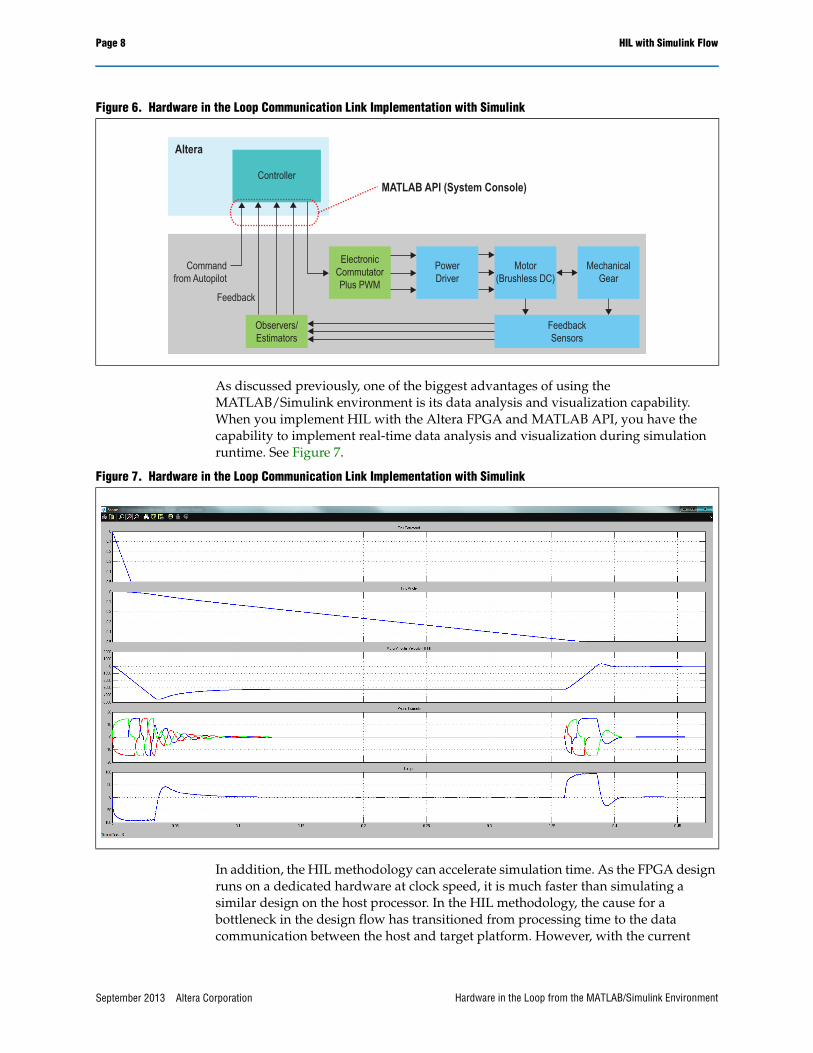
As discussed previously, one of the biggest advantages of using the MATLAB/Simulink environment is its data analysis and visualization capability. When you implement HIL with the Altera FPGA and MATLAB API, you have the capability to implement real-time data analysis and visualization during simulation runtime. See Figure 7.
In addition, the HIL methodology can accelerate simulation time. As the FPGA design runs on a dedicated hardware at clock speed, it is much faster than simulating a similar design on the host processor. In the HIL methodology, the cause for a bottleneck in the design flow has transitioned from processing time to the data communication between the host and target platform. However, with the current
Figure 6. Hardware in the Loop Communication Link Implementation with Simulink
Controller
Electronic
Commutator
Plus PWM
Observers/
Estimators
Power
Driver
Motor
(Brushless DC)
Mechanical
Gear
Command
from Autopilot
Feedback
Sensors
Feedback
Altera
MATLAB API (System Console)
Figure 7. Hardware in the Loop Communication Link Implementation with Simulink
September 2013 Altera Corporation Hardware in the Loop from the MATLAB/Simulink Environment
Conclusion Page 9
implementation of the MATLAB API using JTAG or USB links, you can obtain a significant improvement in simulation runtime compared to cycle-accurate host simulation. In the missile fin control design demo, the HIL methodology obtained an acceleration factor of 50 times compared to software simulation. Moreover, with the increase in design complexity, the advantages of the HIL methodology over software simulation at runtime will be more evident.
ConclusionIn summary, designers can benefit from using the HIL methodology during different stages of the design cycle. The advantages of applying the HIL methodology for design and verification phases are further illustrated with the digital beamforming and missile fin control demo design examples. Altera provides a very flexible infrastructure to implement the software and hardware co-simulation similar to the HIL capability.
Further Information■ Chapter 10: Analyzing and Debugging Designs with the System Console in the
Quartus II Handbookwww.altera.com/literature/hb/qts/qts_qii53028.pdf
Acknowledgements■ Dan Pritsker, Design Engineer, System Solutions Engineering, Altera Corporation
Document Revision HistoryTable 1 shows the revision history for this document.
Table 1. Document Revision History
Date Version Changes
September 2013 1.0 Initial release.
September 2013 Altera CorporationHardware in the Loop from the MATLAB/Simulink Environment