Embed Size (px)
Citation preview
Hardware Assistance for Trustworthy Systemsthrough 3-D Integration
Jonathan Valamehr†, Mohit Tiwari‡, and Timothy Sherwood‡†Department of Electrical and Computer Engineering
‡Department of Computer ScienceUniversity of California, Santa Barbara
Santa Barbara, CA 93106{valamehr@ece,tiwari@cs,sherwood@cs}.ucsb.edu
Ryan KastnerDept. of Computer Science and Engineering
Univ. of California, San DiegoLa Jolla, CA 92093
Ted Huffmire, Cynthia Irvine, and Timothy LevinDept. of Computer ScienceNaval Postgraduate School
Monterey, CA 93943{tdhuffmi,irvine,levin}@nps.edu
Abstract
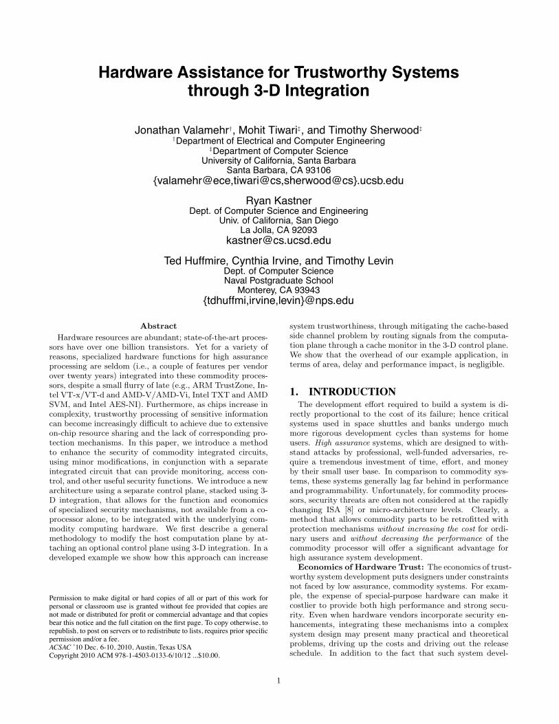
Hardware resources are abundant; state-of-the-art proces-sors have over one billion transistors. Yet for a variety ofreasons, specialized hardware functions for high assuranceprocessing are seldom (i.e., a couple of features per vendorover twenty years) integrated into these commodity proces-sors, despite a small flurry of late (e.g., ARM TrustZone, In-tel VT-x/VT-d and AMD-V/AMD-Vi, Intel TXT and AMDSVM, and Intel AES-NI). Furthermore, as chips increase incomplexity, trustworthy processing of sensitive informationcan become increasingly difficult to achieve due to extensiveon-chip resource sharing and the lack of corresponding pro-tection mechanisms. In this paper, we introduce a methodto enhance the security of commodity integrated circuits,using minor modifications, in conjunction with a separateintegrated circuit that can provide monitoring, access con-trol, and other useful security functions. We introduce a newarchitecture using a separate control plane, stacked using 3-D integration, that allows for the function and economicsof specialized security mechanisms, not available from a co-processor alone, to be integrated with the underlying com-modity computing hardware. We first describe a generalmethodology to modify the host computation plane by at-taching an optional control plane using 3-D integration. In adeveloped example we show how this approach can increase
Permission to make digital or hard copies of all or part of this work forpersonal or classroom use is granted without fee provided that copies arenot made or distributed for profit or commercial advantage and that copiesbear this notice and the full citation on the first page. To copy otherwise, torepublish, to post on servers or to redistribute to lists, requires prior specificpermission and/or a fee.ACSAC ’10 Dec. 6-10, 2010, Austin, Texas USACopyright 2010 ACM 978-1-4503-0133-6/10/12 ...$10.00.
system trustworthiness, through mitigating the cache-basedside channel problem by routing signals from the computa-tion plane through a cache monitor in the 3-D control plane.We show that the overhead of our example application, interms of area, delay and performance impact, is negligible.
1. INTRODUCTIONThe development effort required to build a system is di-
rectly proportional to the cost of its failure; hence criticalsystems used in space shuttles and banks undergo muchmore rigorous development cycles than systems for homeusers. High assurance systems, which are designed to with-stand attacks by professional, well-funded adversaries, re-quire a tremendous investment of time, effort, and moneyby their small user base. In comparison to commodity sys-tems, these systems generally lag far behind in performanceand programmability. Unfortunately, for commodity proces-sors, security threats are often not considered at the rapidlychanging ISA [8] or micro-architecture levels. Clearly, amethod that allows commodity parts to be retrofitted withprotection mechanisms without increasing the cost for ordi-nary users and without decreasing the performance of thecommodity processor will offer a significant advantage forhigh assurance system development.
Economics of Hardware Trust: The economics of trust-worthy system development puts designers under constraintsnot faced by low assurance, commodity systems. For exam-ple, the expense of special-purpose hardware can make itcostlier to provide both high performance and strong secu-rity. Even when hardware vendors incorporate security en-hancements, integrating these mechanisms into a complexsystem design may present many practical and theoreticalproblems, driving up the costs and driving out the releaseschedule. In addition to the fact that such system devel-
1
opment costs per unit are very high, users requiring suchfunctionality make up a small portion of the market. So-phisticated security mechanisms at the hardware level aretypically targeted at a relatively small market sector andadd unacceptable costs to commodity products.Performance Ramifications: The design cycle of trust-
worthy systems also places constraints on the performancethat can be realized in the final version of these systems.Due to the high non-recurring engineering (NRE) cost ofmanufacturing custom hardware and the small amortizationbase of low volume products, manufacturers are often forcedto choose less costly alternatives, such as an older, cheaperprocess (e.g., 0.5um vs. 45nm).As a result of these economic factors, designers of trust-
worthy systems requiring high performance need some wayto incorporate commercial hardware components withoutcompromising security. To address this challenge, a methodof bridging the gap between cutting-edge technology andtrustworthy systems is of paramount necessity.3-D Integration for High Assurance: The primary
goal of this paper is to introduce a new method by which se-curity functionality can be added to a processor as a foundry-level configuration option. Specifically, we propose a newand modular way to add security mechanisms to current andnext-generation processors through the use of 3-D integra-tion. We advocate consolidating these security mechanismsinto a physical overlay, literally a separate plane of circuitrystacked on top of a commodity integrated circuit. The secu-rity mechanisms that reside in this overlay can then be con-nected to the underlying chip with a variety of interconnecttechnologies, yet can be completely omitted without changeto the commodity chip’s function and without affecting itscost. Using 3-D hardware to alleviate this problem offersmany advantages over other hardware solutions as well assoftware solutions. These advantages are fully explored inSection 2.Contributions: In this paper, we show that an active
layer1, which we call a 3-D control plane, specifically dedi-cated to security, has the potential to implement a varietyof security functions in a cost-effective and computationallyefficient way. Specifically, this paper makes the followingcontributions:
• We are the first to develop a method of using 3-Dintegration for trustworthy system development, andpropose to combine an independently fabricated 3-Dcontrol plane containing arbitrary security functions(such as micro-architectural protection mechanisms)along with a commodity integrated circuit, which werefer to as the computation plane.
• Security functions can be broadly classified as eitheractive or passive monitors, depending upon whetherthe 3-D control plane modifies signals on the compu-tation plane. We describe precise circuit-level primi-tives required to build both active and passive moni-tors such that signals on the computation plane can bearbitrarily tapped, disabled, re-routed, or even over-ridden. We also outline how the 3-D control plane can
1The active layer is the silicon layer where transistors re-side, and metal layers are fabricated above that connect thetransistors together. We define a “plane”as the combinationof the silicon and metal layers that compose a typical 2-Dintegrated circuit.
be integrated in a purely optional and minimally in-trusive manner with very minor modification to thecommodity computation plane.
• We demonstrate our circuit-level primitives using anactive monitor that implements a well-known micro-architectural protection mechanism: a cache monitorthat can prevent access-driven cache side channel at-tacks.
• Finally, we validate the functionality of our circuit-level primitives using SPICE simulations, and build asynthesizable prototype of our 3-D cache monitor toevaluate the area-delay cost of its inclusion. We alsoquantify the impact of our cache protection mechanismon the performance of SPEC benchmark programs,through detailed timing simulations on an out-of-orderCPU simulator.
Before describing the circuit-level modifications requiredof the computation plane, we begin with a discussion of 3-Dintegration and the opportunities it presents for trustworthysystem design.
2. MOTIVATION FOR 3-D SECURITYIn this section, we provide a short background on 3-D
integration and present our motivation for using 3-D hard-ware to address the concerns raised in Section 1. Since 3-Dintegration is an existing technology already used in indus-try [24, 26], our work does not discuss the feasibility of 3-Dintegration but rather focuses on the security ramificationsof a 3-D control plane.
2.1 3-D IntegrationWhile the details of how we use this technology are more
fully described in Section 3, the main idea is that two piecesof silicon are fused together to form a single chip. Thetwo active layers of the silicon (the commodity computationplane and 3-D control plane) are connected through inter-die vias2 (micron-width wires that are chemically “drilled-and-filled” between the layers) which run vertically betweenthem. This ability to interconnect multiple active layersenables the addition of an optional die that specifically im-plements security functions to a commodity processor die.This 3-D control plane would have access to the security-dependent signals of the system. Such a system could besold to customers requiring application-specific security pol-icy enforcement, information flow control, or other security-specific support. Commodity systems, on the other hand,are unlikely to include this additional, more costly function-ality that only benefits a small number of customers.
Attaching multiple layers of silicon together in 3-D stacksis a relatively new, yet already marketed technology [26],which is being explored by most of the major microproces-sor manufacturers [6]. As opposed to most current 2-D cir-cuits, which use only one active layer for computation, 3-Dcircuits contain multiple active layers, or planes, which arethen connected using techniques such as inter-die vias (or“posts”). Several 3-D interconnect technologies are currentlybeing evaluated in industry as a means of stacking multi-ple chips together. Some potential applications include the
2Vias are physical connections between two wires on differ-ent metal layers.
2
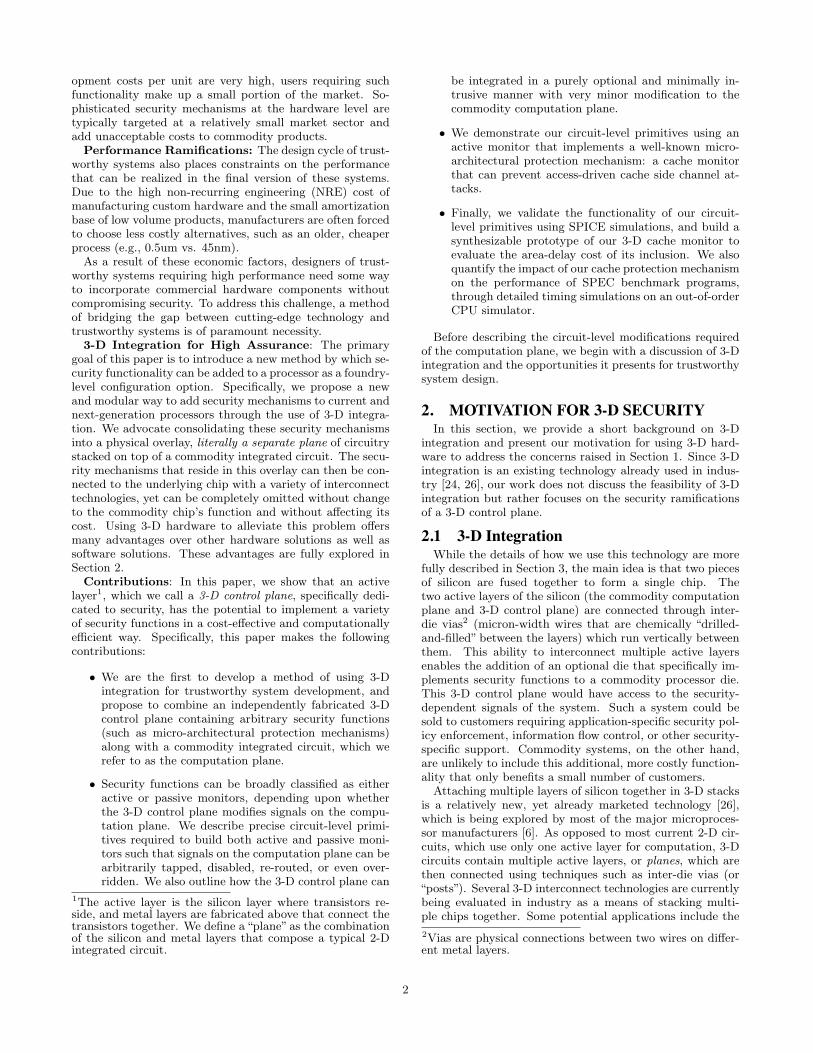
Security Architecture Power Bandwidth Delay
Security Functions On-chip
Security Functions on aCo-Processor
Security Functions on a3-D Control Plane
Low power consumption, withthe only addition being thepower used by security logic andinterconnect
In addition to powering anotherchip, driving long off-chip buswires consumes large amountsof power
3-D security only slightlyincreases power consumption,and can use less power thanon-chip due to exploitation oflocality of security modules
Bus width is limited due tocontending traffic andcomponent congestionthroughout the chip (1-16bytes) running at core clockspeed (>2 GHz)
Low data bus widths due to I/Opin availability (1-8 bytes)running at external clock speed(~ 400 MHz)
3-D allows bus widths to beincreased significantly (up to128 bytes) running at core clockspeed (>2 GHz)
On-chip delay is dictated by thelength of interconnect, which isoften very large betweencomponents
Very large delay between off-chip co-processor and CPU(>200 cycles)
3-D exhibits low delay due to the short length of inter-dievias, as well as the locality that can be exploited to shorten critical paths
Figure 1: This table compares other hardware options for security against a 3-D control plane and shows theadvantages and disadvantages in terms of power, bandwidth, and delay [11, 20].
stacking of DRAM or bigger caches directly onto the pro-cessor die to alleviate memory pressure [17] and designingstacked chips of multiple processors [2].Toshiba has applied 3-D integration to a CMOS image
sensor camera module for mobile phones, which they calla Chip Scale Camera Module (CSCM), achieving a signif-icant reduction in size while satisfying high-speed I/O re-quirements [24]. The Toshiba work demonstrates that costsavings are possible with 3-D integration because passivecomponents, which provide load matching between the chipand the camera, can be integrated into the chip. This makesthe passive components cheaper, smaller, and faster thanboard-level components; therefore, savings can be realizedin power, resistance, and capacitance, as driving lines be-tween layers consumes much less power than between chips.Furthermore, multiple layers, each optimized for its partic-ular function, can be combined into a single stack.Large microprocessor manufacturers are unlikely to inte-
grate support for highly specialized security mechanisms be-cause the market for such features represents such a smallportion of their total customer base. This is an example ofGresham’s Law: if a manufacturer incurs the cost of securitymechanisms deemed unnecessary by the general commod-ity market, a competing, less costly product without suchmechanisms will dominate. By fabricating the optional 3-D control plane with functions that are complementary to(but separate from) those of the main processor, stacked in-terconnect offers the potential to add security mechanismsto a small subset of devices without impacting the overallcost of the commodity processor.Just to be clear, we are advocating the development of
a processor which is always fabricated with special connec-tions built in for joining it with a control plane. The differ-ence between the system sold for the cost-sensitive consumermarket and the one that is sold to the security-sensitive cus-tomer is only whether a specialized security device is actuallystacked on top of the standard integrated circuit, utilizingthe special connections. Additional benefits to this approachare that security mechanisms implemented in hardware arefaster than software-only approaches, and the security mech-anisms can be specialized for particular sets of applications,systems, and customers.
2.2 3-D vs. Other Hardware SolutionsThis section discusses the advantages of using 3-D integra-
tion over other hardware methods such as on-chip and co-processor implementation of security functions. In general,implementing security functions in software is less costlythan in hardware, but software implementations have worseperformance and are more susceptible to tampering. Imple-menting security functions in hardware is more expensive,but the result has better performance and is more resilientto manipulation.
Why not On-Chip?: Implementing security featureson-chip creates many issues and discrepancies. It wouldforce all users of the chip uninterested in system trustwor-thiness to incur the possible negative effects of the addedsecurity logic. As discussed previously, an unacceptableconsequence of on-chip security is the increase in cost forall consumers. In addition, on-chip security functions havethe potential of decreasing the overall performance of thechip, as security modules may need long interconnect wiresto data and control lines spanning the whole chip area; thiscan be mitigated by the exploitation of locality in the 3-Dlayer as well as short interconnect through inter-die vias asexplained in Figure 1. The large majority of microproces-sor consumers are chiefly concerned with the performance ofthe chip, and on-chip security could provide advantages tocompeting chip manufacturers who do not incorporate thesesecurity features. Because of market pressures, chip manu-facturers are reluctant to pursue such a course. With 3-Dsecurity, the small percentage of consumers who need theadded security logic have the option of including it in theirsystems, while consumers who do not need this extra logiccan omit it.
Why not use a Co-processor?: A co-processor solu-tion, much like 3-D security, allows the consumer to have theoption of including additional security logic. However, un-like 3-D security, an off-chip co-processor can not safely ac-cess internal micro-architectural control signals without pos-sibly making them susceptible to outside tampering. Thismakes 3-D security much more attractive and feasible, asany resource or control signal can be accessed and modifiedby the 3-D control plane. Also, co-processor solutions suf-
3
fer from the utilization of slow, power-hungry off-chip buses.These off-chip buses operate at much slower frequencies thancan be realized with a 3-D solution (Figure 1), and they canintroduce large delays in processor speed. In addition, off-chip buses have to interface with the main processor throughthe main processor’s I/O pins, and they are limited in sizebased on available pins. This equates to smaller bus widths(Figure 1), which can further hinder performance. Choos-ing which pins to interface between the processor and theco-processor also creates inflexible co-processor designs, be-cause we are limited to accessing or modifying those pins,whereas with a 3-D solution we can create any number ofdifferent co-processor designs and access any internal signal.Aside from performance, a co-processor solution also entailsincreased power usage, as driving long off-chip buses requiresmuch more power than driving short inter-die vias to a 3-Dcontrol plane. A 3-D security scheme does not fall victim toany of these issues.Disadvantages of 3-D Security: 3-D security holds
much promise as a solution; however, it is not without trade-offs. Chips fabricated using 3-D integration need greaterthermal management, and, without additional cooling, willrun at higher temperatures due to the proximity of com-ponents [11]. While this is a known issue, it is not insur-mountable and can be addressed with more expensive cool-ing solutions. Another disadvantage of 3-D chips is theirexpected manufacturing yield, as the functionality of thecomplete chip is dependent on the individual yield of eachof the two dies.This can create lower overall yield than theindividual dies. However, the cost of this lower yield willnot be incurred by most consumers, as the decrease in yieldonly applies to the systems that need the 3-D control planeattached.This section has compared 3-D security with other soft-
ware and hardware solutions for trustworthy systems. The3-D control plane can include different types of security mon-itors. In the next section, we will discuss both of these typesof monitors, and follow with our novel circuit architectureto allow the use of an optional 3-D control plane.
3. 3-D SECURITY ARCHITECTUREThe 3-D control plane can include several security func-
tions on one die, implemented as either passive or activemonitors. While passive monitoring in 3-D for system pro-filing has been explored previously [12], a novel contributionof this work is providing active monitoring in a 3-D con-trol plane. In the following section we explain the uses ofthese two types of monitors, and describe a novel circuit-level architecture that allows us to make the functions ofthese monitors available as a fabrication option in an over-lay.
3.1 Passive and Active MonitorsPassive Monitors: One potential use of the 3-D control
plane is to act as a passive monitor, simply accessing andanalyzing data from the computation plane. For instance,we may wish to monitor accesses to a particular region ofmemory or audit the use of a particular set of instructions.To monitor these events, we must understand when suchevents are occurring, which necessitates tapping some of thewires from the processor. This requires posts and vias tothe instruction register and memory wires, which gives us
direct access to the currently executing instruction.Passive monitoring is reasonably straightforward to im-
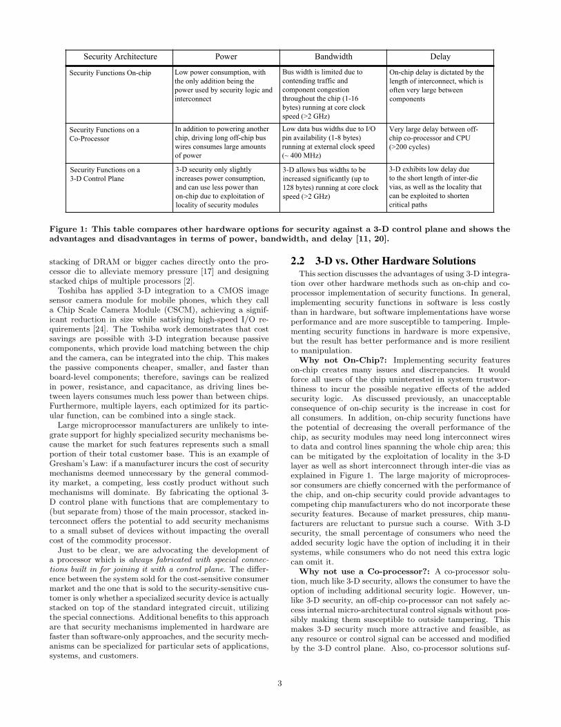
plement in 3-D technology, as it just requires a set of viasto the top of the computation plane, and then a post fromthere to the 3-D control plane. Figure 2 shows such a post.
3-D
Con
trol
Plan
eC
ompu
tatio
nPl
ane
Reference
TSV
Sleep Transistors
Buffer
bus
MetalLayers
Silicon Substrate
vias
CMOSLogic
TSV
Post Carries Rerouted
MetalLayers
MonitorLogic
Signal from Computation Plane
Diabled byBus Is
Contact Point
Figure 2: This figure shows the low level architec-ture for a method to route data/control lines on thecomputation plane through the 3-D control plane.This can be performed to isolate resources in thecomputation plane by disabling a bus, for example.The computation plane and the 3-D control planeare connected by inter-die vias or through-siliconvias (TSVs). Posts are required to tap the requiredsignals needed by the security logic, and sleep tran-sistors are used to either reroute, override, or dis-able lines on the computation plane. Using theseprimitives, we can build mechanisms to monitor thecomputation plane.
The area overhead of this passive style monitoring in a 3-D layer was analyzed by Mysore et al. [12] in the context ofhardware support for analyzing the processor in real timefor debugging and performance profiling, which has highthroughput requirements and is very slow to implement insoftware. Their conclusion was that, even with very pes-simistic assumptions about the technology, there would beless than a 2% increase in the total area on the computationplane and that there would be no noticeable delay added.The small amount of area overhead is due to the need tosave space for the vias across all of the layers of metal.
Active Monitors: Whereas passive monitoring allowsfor auditing, anomaly detection, and the identification ofsuspicious activities, systems enforcing security policies of-ten require strong guarantees about restrictions to overallsystem behavior. A novel contribution of our work is theemployment of active monitors; an active monitor enablescontrol of information flow between cores, the arbitration ofcommunication, and the partitioning of resources.
The key ability needed to support such functionality is toreroute signals to the 3-D control plane and then overridethem with potentially modified signals. With this technol-ogy and minor modification of the computation plane, we
4
can force all inter-core communication, memory accesses,and shared signals to travel to the 3-D control plane, wherethey are subject to both examination and control. For in-stance, we can ensure that confidential data being sent be-tween two cores (which are traditionally forced to traversea shared bus) is not leaked to a third party with access tothat bus.We have developed a method to modify signals on the
computation plane that is accomplished in two parts. Thefirst part is to ensure that the monitor has unfettered accessto all the signals (tapping), which is, in essence, the sameas the passive monitoring scenario described above. Thesecond part is to selectively disable those links, essentiallyturning off portions of the computation plane (e.g., a bus),or overriding them to inject different values. The difficultyis that we must remove a capability (the connection betweentwo components) only by adding a 3-D control plane (whichcannot physically cut or impede that wire). The compu-tation plane must be fully functional without an attached3-D control plane, yet it needs to be constructed so that byadding circuitry, the targeted capability can be completelydisabled. To accomplish this, components in the computa-tion plane must be modified to support active monitoring.
3.2 Circuit-level ModificationsThis section introduces the circuit level modifications we
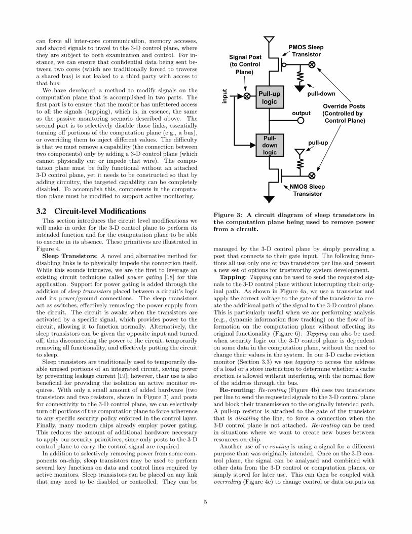
will make in order for the 3-D control plane to perform itsintended function and for the computation plane to be ableto execute in its absence. These primitives are illustrated inFigure 4.Sleep Transistors: A novel and alternative method for
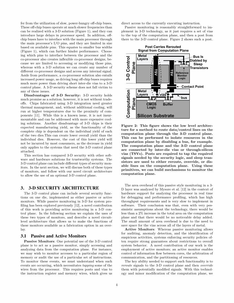
disabling links is to physically impede the connection itself.While this sounds intrusive, we are the first to leverage anexisting circuit technique called power gating [18] for thisapplication. Support for power gating is added through theaddition of sleep transistors placed between a circuit’s logicand its power/ground connections. The sleep transistorsact as switches, effectively removing the power supply fromthe circuit. The circuit is awake when the transistors areactivated by a specific signal, which provides power to thecircuit, allowing it to function normally. Alternatively, thesleep transistors can be given the opposite input and turnedoff, thus disconnecting the power to the circuit, temporarilyremoving all functionality, and effectively putting the circuitto sleep.Sleep transistors are traditionally used to temporarily dis-
able unused portions of an integrated circuit, saving powerby preventing leakage current [19]; however, their use is alsobeneficial for providing the isolation an active monitor re-quires. With only a small amount of added hardware (twotransistors and two resistors, shown in Figure 3) and postsfor connectivity to the 3-D control plane, we can selectivelyturn off portions of the computation plane to force adherenceto any specific security policy enforced in the control layer.Finally, many modern chips already employ power gating.This reduces the amount of additional hardware necessaryto apply our security primitives, since only posts to the 3-Dcontrol plane to carry the control signal are required.In addition to selectively removing power from some com-
ponents on-chip, sleep transistors may be used to performseveral key functions on data and control lines required byactive monitors. Sleep transistors can be placed on any linkthat may need to be disabled or controlled. They can be
Pull-uplogicin
put
output
pull-down
pull-up
Signal Post (to Control
Plane)
Pull-downlogic
PMOS SleepTransistor
NMOS SleepTransistor
Override Posts (Controlled byControl Plane)
Figure 3: A circuit diagram of sleep transistors inthe computation plane being used to remove powerfrom a circuit.
managed by the 3-D control plane by simply providing apost that connects to their gate input. The following func-tions all use only one or two transistors per line and presenta new set of options for trustworthy system development.
Tapping: Tapping can be used to send the requested sig-nals to the 3-D control plane without interrupting their orig-inal path. As shown in Figure 4a, we use a transistor andapply the correct voltage to the gate of the transistor to cre-ate the additional path of the signal to the 3-D control plane.This is particularly useful when we are performing analysis(e.g., dynamic information flow tracking) on the flow of in-formation on the computation plane without affecting itsoriginal functionality (Figure 6). Tapping can also be usedwhen security logic on the 3-D control plane is dependenton some data in the computation plane, without the need tochange their values in the system. In our 3-D cache evictionmonitor (Section 3.3) we use tapping to access the addressof a load or a store instruction to determine whether a cacheeviction is allowed without interfering with the normal flowof the address through the bus.
Re-routing: Re-routing (Figure 4b) uses two transistorsper line to send the requested signals to the 3-D control planeand block their transmission to the originally intended path.A pull-up resistor is attached to the gate of the transistorthat is disabling the line, to force a connection when the3-D control plane is not attached. Re-routing can be usedin situations where we want to create new buses betweenresources on-chip.
Another use of re-routing is using a signal for a differentpurpose than was originally intended. Once on the 3-D con-trol plane, the signal can be analyzed and combined withother data from the 3-D control or computation planes, orsimply stored for later use. This can then be coupled withoverriding (Figure 4c) to change control or data outputs on
5
(a) Tapping (b) Re-routing
X
X
(c) Overriding
X
(d) Disabling
X
X
X
= Post to the 3-D control plane X = Signal flow
X
X
X
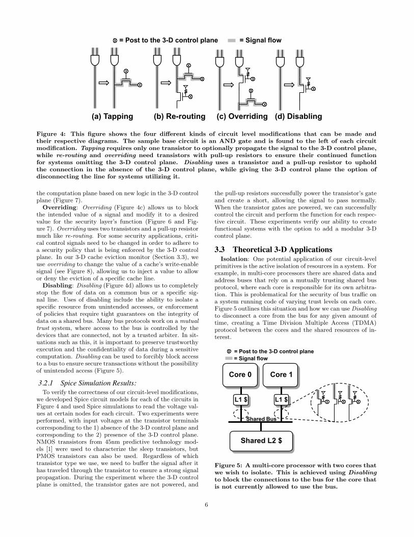
Figure 4: This figure shows the four different kinds of circuit level modifications that can be made andtheir respective diagrams. The sample base circuit is an AND gate and is found to the left of each circuitmodification. Tapping requires only one transistor to optionally propagate the signal to the 3-D control plane,while re-routing and overriding need transistors with pull-up resistors to ensure their continued functionfor systems omitting the 3-D control plane. Disabling uses a transistor and a pull-up resistor to upholdthe connection in the absence of the 3-D control plane, while giving the 3-D control plane the option ofdisconnecting the line for systems utilizing it.
the computation plane based on new logic in the 3-D controlplane (Figure 7).Overriding: Overriding (Figure 4c) allows us to block
the intended value of a signal and modify it to a desiredvalue for the security layer’s function (Figure 6 and Fig-ure 7). Overriding uses two transistors and a pull-up resistormuch like re-routing. For some security applications, criti-cal control signals need to be changed in order to adhere toa security policy that is being enforced by the 3-D controlplane. In our 3-D cache eviction monitor (Section 3.3), weuse overriding to change the value of a cache’s write-enablesignal (see Figure 8), allowing us to inject a value to allowor deny the eviction of a specific cache line.Disabling: Disabling (Figure 4d) allows us to completely
stop the flow of data on a common bus or a specific sig-nal line. Uses of disabling include the ability to isolate aspecific resource from unintended accesses, or enforcementof policies that require tight guarantees on the integrity ofdata on a shared bus. Many bus protocols work on a mutualtrust system, where access to the bus is controlled by thedevices that are connected, not by a trusted arbiter. In sit-uations such as this, it is important to preserve trustworthyexecution and the confidentiality of data during a sensitivecomputation. Disabling can be used to forcibly block accessto a bus to ensure secure transactions without the possibilityof unintended access (Figure 5).
3.2.1 Spice Simulation Results:To verify the correctness of our circuit-level modifications,
we developed Spice circuit models for each of the circuits inFigure 4 and used Spice simulations to read the voltage val-ues at certain nodes for each circuit. Two experiments wereperformed, with input voltages at the transistor terminalscorresponding to the 1) absence of the 3-D control plane andcorresponding to the 2) presence of the 3-D control plane.NMOS transistors from 45nm predictive technology mod-els [1] were used to characterize the sleep transistors, butPMOS transistors can also be used. Regardless of whichtransistor type we use, we need to buffer the signal after ithas traveled through the transistor to ensure a strong signalpropagation. During the experiment where the 3-D controlplane is omitted, the transistor gates are not powered, and
the pull-up resistors successfully power the transistor’s gateand create a short, allowing the signal to pass normally.When the transistor gates are powered, we can successfullycontrol the circuit and perform the function for each respec-tive circuit. These experiments verify our ability to createfunctional systems with the option to add a modular 3-Dcontrol plane.
3.3 Theoretical 3-D ApplicationsIsolation: One potential application of our circuit-level
primitives is the active isolation of resources in a system. Forexample, in multi-core processors there are shared data andaddress buses that rely on a mutually trusting shared busprotocol, where each core is responsible for its own arbitra-tion. This is problematical for the security of bus traffic ona system running code of varying trust levels on each core.Figure 5 outlines this situation and how we can use Disablingto disconnect a core from the bus for any given amount oftime, creating a Time Division Multiple Access (TDMA)protocol between the cores and the shared resources of in-terest.
Shared L2 $
Core 1
L1 $
Core 0
L1 $ XXX
Shared Bus
= Post to the 3-D control planeX
= Signal flow
��
Figure 5: A multi-core processor with two cores thatwe wish to isolate. This is achieved using Disablingto block the connections to the bus for the core thatis not currently allowed to use the bus.
6
Standard Execution Pipeline
Tag Prop. Logic
3-DControl
Plane
Com
puta
tion
Plan
e
1. Instruction bits 2. Tag miss exception signal
Reg File
L1 $
Control Logic
Tag Reg File
Range $
X
X
X
XX
X
X
1. 2.
� �
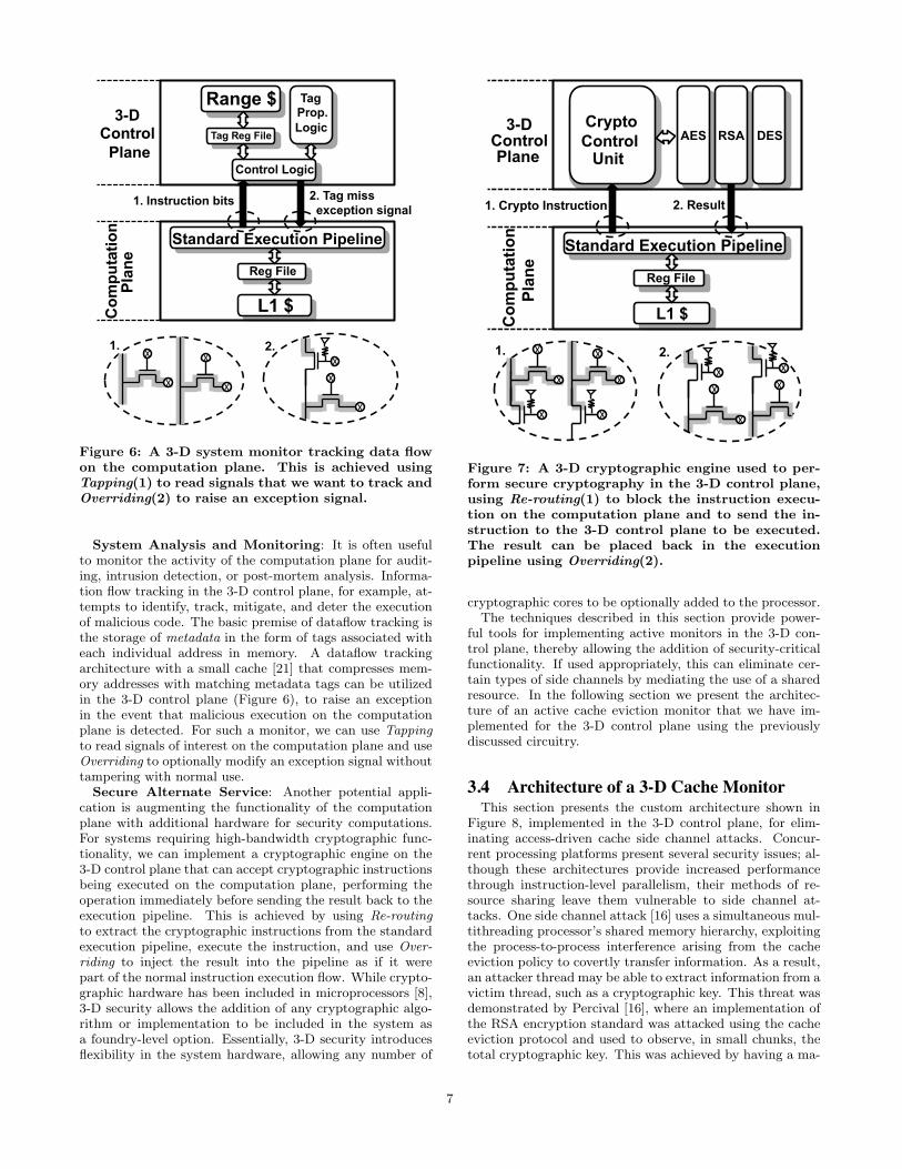
Figure 6: A 3-D system monitor tracking data flowon the computation plane. This is achieved usingTapping(1) to read signals that we want to track andOverriding(2) to raise an exception signal.
System Analysis and Monitoring: It is often usefulto monitor the activity of the computation plane for audit-ing, intrusion detection, or post-mortem analysis. Informa-tion flow tracking in the 3-D control plane, for example, at-tempts to identify, track, mitigate, and deter the executionof malicious code. The basic premise of dataflow tracking isthe storage of metadata in the form of tags associated witheach individual address in memory. A dataflow trackingarchitecture with a small cache [21] that compresses mem-ory addresses with matching metadata tags can be utilizedin the 3-D control plane (Figure 6), to raise an exceptionin the event that malicious execution on the computationplane is detected. For such a monitor, we can use Tappingto read signals of interest on the computation plane and useOverriding to optionally modify an exception signal withouttampering with normal use.Secure Alternate Service: Another potential appli-
cation is augmenting the functionality of the computationplane with additional hardware for security computations.For systems requiring high-bandwidth cryptographic func-tionality, we can implement a cryptographic engine on the3-D control plane that can accept cryptographic instructionsbeing executed on the computation plane, performing theoperation immediately before sending the result back to theexecution pipeline. This is achieved by using Re-routingto extract the cryptographic instructions from the standardexecution pipeline, execute the instruction, and use Over-riding to inject the result into the pipeline as if it werepart of the normal instruction execution flow. While crypto-graphic hardware has been included in microprocessors [8],3-D security allows the addition of any cryptographic algo-rithm or implementation to be included in the system asa foundry-level option. Essentially, 3-D security introducesflexibility in the system hardware, allowing any number of
Standard Execution Pipeline
AES3-D
Control Plane
1. Crypto Instruction 2. Result
Reg File
L1 $
Crypto Control
X
X
X
XX
X
1. 2.
Com
puta
tion
Plan
e
RSA DES
XX
X
X
X
� � � �
Unit
Figure 7: A 3-D cryptographic engine used to per-form secure cryptography in the 3-D control plane,using Re-routing(1) to block the instruction execu-tion on the computation plane and to send the in-struction to the 3-D control plane to be executed.The result can be placed back in the executionpipeline using Overriding(2).
cryptographic cores to be optionally added to the processor.The techniques described in this section provide power-
ful tools for implementing active monitors in the 3-D con-trol plane, thereby allowing the addition of security-criticalfunctionality. If used appropriately, this can eliminate cer-tain types of side channels by mediating the use of a sharedresource. In the following section we present the architec-ture of an active cache eviction monitor that we have im-plemented for the 3-D control plane using the previouslydiscussed circuitry.
3.4 Architecture of a 3-D Cache MonitorThis section presents the custom architecture shown in
Figure 8, implemented in the 3-D control plane, for elim-inating access-driven cache side channel attacks. Concur-rent processing platforms present several security issues; al-though these architectures provide increased performancethrough instruction-level parallelism, their methods of re-source sharing leave them vulnerable to side channel at-tacks. One side channel attack [16] uses a simultaneous mul-tithreading processor’s shared memory hierarchy, exploitingthe process-to-process interference arising from the cacheeviction policy to covertly transfer information. As a result,an attacker thread may be able to extract information from avictim thread, such as a cryptographic key. This threat wasdemonstrated by Percival [16], where an implementation ofthe RSA encryption standard was attacked using the cacheeviction protocol and used to observe, in small chunks, thetotal cryptographic key. This was achieved by having a ma-
7
Mem
Cache
CPU =Cache
Controller
Write Enable
Hit?
V
Inde
xTa
g
Tag
Cac
he D
ata
Memory Data
Data
R/WData Address
PID
Lock bit
=
Grant
Address
Lock
ed?
PID
Security Bits
Computation Plane
3-D Control Plane
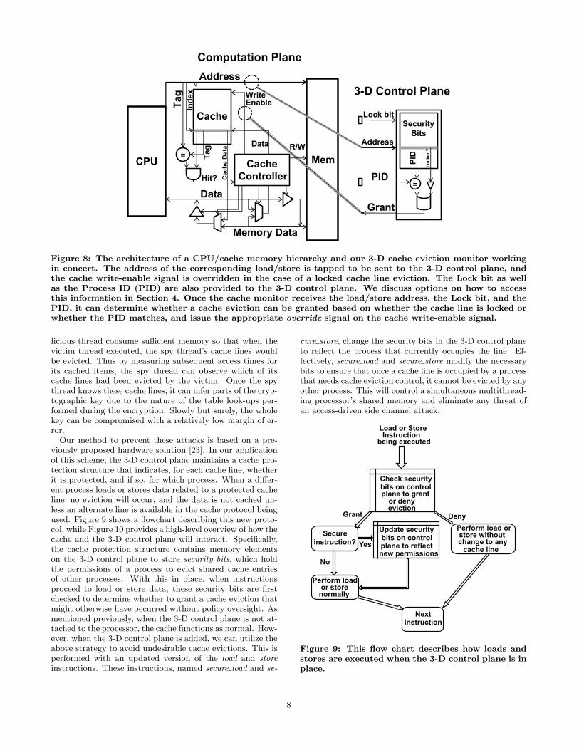
Figure 8: The architecture of a CPU/cache memory hierarchy and our 3-D cache eviction monitor workingin concert. The address of the corresponding load/store is tapped to be sent to the 3-D control plane, andthe cache write-enable signal is overridden in the case of a locked cache line eviction. The Lock bit as wellas the Process ID (PID) are also provided to the 3-D control plane. We discuss options on how to accessthis information in Section 4. Once the cache monitor receives the load/store address, the Lock bit, and thePID, it can determine whether a cache eviction can be granted based on whether the cache line is locked orwhether the PID matches, and issue the appropriate override signal on the cache write-enable signal.
licious thread consume sufficient memory so that when thevictim thread executed, the spy thread’s cache lines wouldbe evicted. Thus by measuring subsequent access times forits cached items, the spy thread can observe which of itscache lines had been evicted by the victim. Once the spythread knows these cache lines, it can infer parts of the cryp-tographic key due to the nature of the table look-ups per-formed during the encryption. Slowly but surely, the wholekey can be compromised with a relatively low margin of er-ror.Our method to prevent these attacks is based on a pre-
viously proposed hardware solution [23]. In our applicationof this scheme, the 3-D control plane maintains a cache pro-tection structure that indicates, for each cache line, whetherit is protected, and if so, for which process. When a differ-ent process loads or stores data related to a protected cacheline, no eviction will occur, and the data is not cached un-less an alternate line is available in the cache protocol beingused. Figure 9 shows a flowchart describing this new proto-col, while Figure 10 provides a high-level overview of how thecache and the 3-D control plane will interact. Specifically,the cache protection structure contains memory elementson the 3-D control plane to store security bits, which holdthe permissions of a process to evict shared cache entriesof other processes. With this in place, when instructionsproceed to load or store data, these security bits are firstchecked to determine whether to grant a cache eviction thatmight otherwise have occurred without policy oversight. Asmentioned previously, when the 3-D control plane is not at-tached to the processor, the cache functions as normal. How-ever, when the 3-D control plane is added, we can utilize theabove strategy to avoid undesirable cache evictions. This isperformed with an updated version of the load and storeinstructions. These instructions, named secure load and se-
cure store, change the security bits in the 3-D control planeto reflect the process that currently occupies the line. Ef-fectively, secure load and secure store modify the necessarybits to ensure that once a cache line is occupied by a processthat needs cache eviction control, it cannot be evicted by anyother process. This will control a simultaneous multithread-ing processor’s shared memory and eliminate any threat ofan access-driven side channel attack.
Perform load or store without change to any
cache line
Load or Store Instruction
being executed
Deny
Secure instruction?
Grant
Yes
No
Update security bits on control plane to reflect new permissions
Perform load or store
normally
Next Instruction
Check security bits on control plane to grant
or deny eviction
Figure 9: This flow chart describes how loads andstores are executed when the 3-D control plane is inplace.
8
Cache/Cache Controller
3-D Control Plane
Address
Grant
To Processor
Security bits
V PID L
Responsible for two main functions: 1. Given any load or store; return whether cache eviction is granted 2. Given secure load or store; update security bits on control plane
To Memory
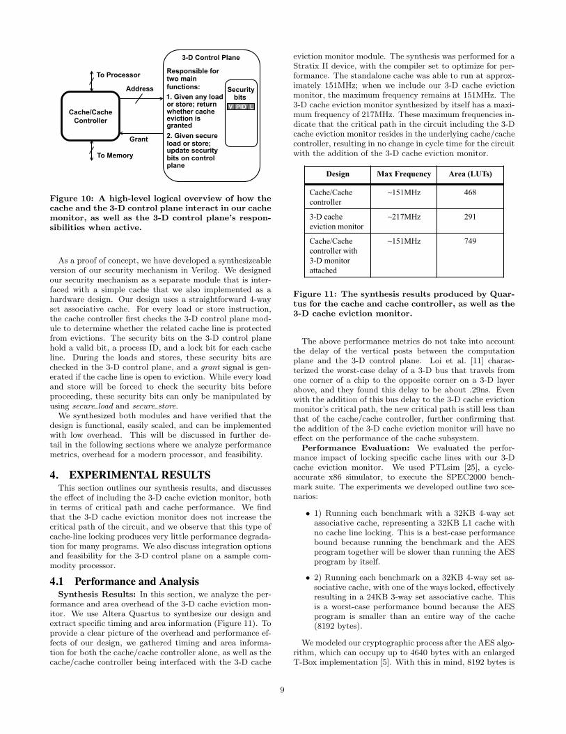
Figure 10: A high-level logical overview of how thecache and the 3-D control plane interact in our cachemonitor, as well as the 3-D control plane’s respon-sibilities when active.
As a proof of concept, we have developed a synthesizeableversion of our security mechanism in Verilog. We designedour security mechanism as a separate module that is inter-faced with a simple cache that we also implemented as ahardware design. Our design uses a straightforward 4-wayset associative cache. For every load or store instruction,the cache controller first checks the 3-D control plane mod-ule to determine whether the related cache line is protectedfrom evictions. The security bits on the 3-D control planehold a valid bit, a process ID, and a lock bit for each cacheline. During the loads and stores, these security bits arechecked in the 3-D control plane, and a grant signal is gen-erated if the cache line is open to eviction. While every loadand store will be forced to check the security bits beforeproceeding, these security bits can only be manipulated byusing secure load and secure store.We synthesized both modules and have verified that the
design is functional, easily scaled, and can be implementedwith low overhead. This will be discussed in further de-tail in the following sections where we analyze performancemetrics, overhead for a modern processor, and feasibility.
4. EXPERIMENTAL RESULTSThis section outlines our synthesis results, and discusses
the effect of including the 3-D cache eviction monitor, bothin terms of critical path and cache performance. We findthat the 3-D cache eviction monitor does not increase thecritical path of the circuit, and we observe that this type ofcache-line locking produces very little performance degrada-tion for many programs. We also discuss integration optionsand feasibility for the 3-D control plane on a sample com-modity processor.
4.1 Performance and AnalysisSynthesis Results: In this section, we analyze the per-
formance and area overhead of the 3-D cache eviction mon-itor. We use Altera Quartus to synthesize our design andextract specific timing and area information (Figure 11). Toprovide a clear picture of the overhead and performance ef-fects of our design, we gathered timing and area informa-tion for both the cache/cache controller alone, as well as thecache/cache controller being interfaced with the 3-D cache
eviction monitor module. The synthesis was performed for aStratix II device, with the compiler set to optimize for per-formance. The standalone cache was able to run at approx-imately 151MHz; when we include our 3-D cache evictionmonitor, the maximum frequency remains at 151MHz. The3-D cache eviction monitor synthesized by itself has a maxi-mum frequency of 217MHz. These maximum frequencies in-dicate that the critical path in the circuit including the 3-Dcache eviction monitor resides in the underlying cache/cachecontroller, resulting in no change in cycle time for the circuitwith the addition of the 3-D cache eviction monitor.
Design Max Frequency Area (LUTs)
Cache/Cachecontroller
~151MHz 468
3-D cacheeviction monitor
~217MHz 291
Cache/Cache controller with 3-D monitorattached
~151MHz 749
Figure 11: The synthesis results produced by Quar-tus for the cache and cache controller, as well as the3-D cache eviction monitor.
The above performance metrics do not take into accountthe delay of the vertical posts between the computationplane and the 3-D control plane. Loi et al. [11] charac-terized the worst-case delay of a 3-D bus that travels fromone corner of a chip to the opposite corner on a 3-D layerabove, and they found this delay to be about .29ns. Evenwith the addition of this bus delay to the 3-D cache evictionmonitor’s critical path, the new critical path is still less thanthat of the cache/cache controller, further confirming thatthe addition of the 3-D cache eviction monitor will have noeffect on the performance of the cache subsystem.
Performance Evaluation: We evaluated the perfor-mance impact of locking specific cache lines with our 3-Dcache eviction monitor. We used PTLsim [25], a cycle-accurate x86 simulator, to execute the SPEC2000 bench-mark suite. The experiments we developed outline two sce-narios:
• 1) Running each benchmark with a 32KB 4-way setassociative cache, representing a 32KB L1 cache withno cache line locking. This is a best-case performancebound because running the benchmark and the AESprogram together will be slower than running the AESprogram by itself.
• 2) Running each benchmark on a 32KB 4-way set as-sociative cache, with one of the ways locked, effectivelyresulting in a 24KB 3-way set associative cache. Thisis a worst-case performance bound because the AESprogram is smaller than an entire way of the cache(8192 bytes).
We modeled our cryptographic process after the AES algo-rithm, which can occupy up to 4640 bytes with an enlargedT-Box implementation [5]. With this in mind, 8192 bytes is
9
-1.4%
-1.2%
-1.0%
-0.8%
-0.6%
-0.4%
-0.2%
0.0%
0.2%
0.4%
0.6%
0.8%
1.0%
188.
amm
p (m
ed)
173.
appl
u (lg
) 30
1.ap
si (l
g)
179.
art (
lg)
256.
bzip
2 (lg
/pro
g)
256.
bzip
2 (lg
/src
) 18
6.cr
afty
(med
) 18
3.eq
uake
(lg)
18
3.eq
uake
(tes
t) 25
4.ga
p (lg
) 17
6.gc
c (m
ed)
164.
gzip
(sm
/src
) 16
4.gz
ip (s
m/p
rog)
18
1.m
cf (l
g)
172.
mgr
id (l
g)
197.
pars
er (m
ed)
253.
perlb
mk
(sm
) 17
1.sw
im (l
g)
300.
twol
f (sm
) 25
5.vo
rtex
(lg)
17
5.vp
r (pl
ace/
sm)
175.
vpr (
rout
e/sm
) 16
8.w
upw
ise
(lg)
aver
age
Incr
ease
in IP
C (%
)
Benchmark
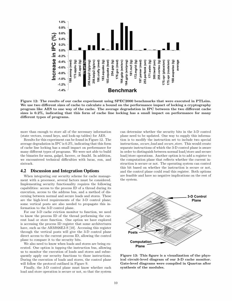
Figure 12: The results of our cache experiment using SPEC2000 benchmarks that were executed in PTLsim.We use two different sizes of cache to calculate a bound on the performance impact of locking a cryptographyprogram like AES to one way of the cache. The average degradation in IPC between the two different cachesizes is 0.2%, indicating that this form of cache line locking has a small impact on performance for manydifferent types of programs.
more than enough to store all of the necessary information(state vectors, round keys, and look-up tables) for AES.Results for this experiment can be found in Figure 12. The
average degradation in IPC is 0.2%, indicating that this formof cache line locking has a small impact on performance formany different types of programs. We were not able to buildthe binaries for mesa, galgel, facerec, or fma3d. In addition,we encountered technical difficulties with lucas, eon, andsixtrack.
4.2 Discussion and Integration OptionsWhen integrating our security scheme for cache manage-
ment with a processor, several factors must be considered.Implementing security functionality requires the followingcapabilities: access to the process ID of a thread during itsexecution, access to the address bus, and a method of dis-cerning between normal and secure loads and stores. Theseare the high-level requirements of the 3-D control plane;some vertical posts are also needed to propagate this in-formation to the 3-D control plane.For our 3-D cache eviction monitor to function, we need
to know the process ID of the thread performing the cur-rent load or store function. One option we have exploredis accessing the process ID register that some architectureshave, such as the ARM926EJ-S [10]. Accessing this registerthrough the vertical posts will give the 3-D control planedirect access to the current process ID, allowing the controlplane to compare it to the security bits.We also need to know when loads and stores are being ex-
ecuted. One option is tapping the instruction bus, allowingus to monitor the execution of loads and stores and subse-quently apply our security functions to those instructions.During the execution of loads and stores, the control planewill follow the protocol outlined in Figure 9.Finally, the 3-D control plane must know whether each
load and store operation is secure or not, so that the system
can determine whether the security bits in the 3-D controlplane need to be updated. One way to supply this informa-tion is to modify the instruction set to include two specialinstructions, secure load and secure store. This would createseparate instructions of which the 3-D control plane is awarein order to distinguish between normal load/store and secureload/store operations. Another option is to add a register tothe computation plane that reflects whether the current in-struction is secure or not. The operating system can controlthis bit based on whether the instruction is secure or not,and the control plane could read this register. Both optionsare feasible and have no negative implications on the rest ofthe system.
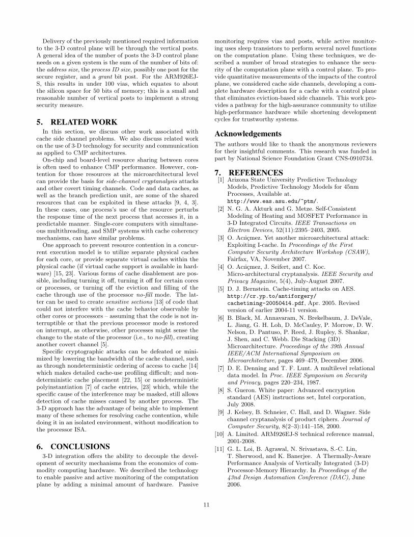
3-D ControlPlane
ComputationPlane
Posts
Figure 13: This figure is a visualization of the phys-ical circuit-level diagram of our 3-D cache monitor.Gate-level diagrams were compiled in Quartus aftersynthesis of the modules.
10
Delivery of the previously mentioned required informationto the 3-D control plane will be through the vertical posts.A general idea of the number of posts the 3-D control planeneeds on a given system is the sum of the number of bits of:the address size, the process ID size, possibly one post for thesecure register, and a grant bit post. For the ARM926EJ-S, this results in under 100 vias, which equates to aboutthe silicon space for 50 bits of memory; this is a small andreasonable number of vertical posts to implement a strongsecurity measure.
5. RELATEDWORKIn this section, we discuss other work associated with
cache side channel problems. We also discuss related workon the use of 3-D technology for security and communicationas applied to CMP architectures.On-chip and board-level resource sharing between cores
is often used to enhance CMP performance. However, con-tention for those resources at the microarchitectural levelcan provide the basis for side-channel cryptanalysis attacksand other covert timing channels. Code and data caches, aswell as the branch prediction unit, are some of the sharedresources that can be exploited in these attacks [9, 4, 3].In these cases, one process’s use of the resource perturbsthe response time of the next process that accesses it, in apredictable manner. Single-core computers with simultane-ous multithreading, and SMP systems with cache coherencymechanisms, can have similar problems.One approach to prevent resource contention in a concur-
rent execution model is to utilize separate physical cachesfor each core, or provide separate virtual caches within thephysical cache (if virtual cache support is available in hard-ware) [15, 23]. Various forms of cache disablement are pos-sible, including turning it off, turning it off for certain coresor processes, or turning off the eviction and filling of thecache through use of the processor no-fill mode. The lat-ter can be used to create sensitive sections [13] of code thatcould not interfere with the cache behavior observable byother cores or processors – assuming that the code is not in-terruptible or that the previous processor mode is restoredon interrupt, as otherwise, other processes might sense thechange to the state of the processor (i.e., to no-fill), creatinganother covert channel [5].Specific cryptographic attacks can be defeated or mini-
mized by lowering the bandwidth of the cache channel, suchas through nondeterministic ordering of access to cache [14]which makes detailed cache-use profiling difficult; and non-deterministic cache placement [22, 15] or nondeterministicpolyinstantiation [7] of cache entries, [23] which, while thespecific cause of the interference may be masked, still allowsdetection of cache misses caused by another process. The3-D approach has the advantage of being able to implementmany of these schemes for resolving cache contention, whiledoing it in an isolated environment, without modification tothe processor ISA.
6. CONCLUSIONS3-D integration offers the ability to decouple the devel-
opment of security mechanisms from the economics of com-modity computing hardware. We described the technologyto enable passive and active monitoring of the computationplane by adding a minimal amount of hardware. Passive
monitoring requires vias and posts, while active monitor-ing uses sleep transistors to perform several novel functionson the computation plane. Using these techniques, we de-scribed a number of broad strategies to enhance the secu-rity of the computation plane with a control plane. To pro-vide quantitative measurements of the impacts of the controlplane, we considered cache side channels, developing a com-plete hardware description for a cache with a control planethat eliminates eviction-based side channels. This work pro-vides a pathway for the high-assurance community to utilizehigh-performance hardware while shortening developmentcycles for trustworthy systems.
AcknowledgementsThe authors would like to thank the anonymous reviewersfor their insightful comments. This research was funded inpart by National Science Foundation Grant CNS-0910734.
7. REFERENCES[1] Arizona State University Predictive Technology
Models, Predictive Technology Models for 45nmProcesses, Available at.http://www.eas.asu.edu/~ptm/.
[2] N. G. A. Akturk and G. Metze. Self-ConsistentModeling of Heating and MOSFET Performance in3-D Integrated Circuits. IEEE Transactions onElectron Devices, 52(11):2395–2403, 2005.
[3] O. Acıicmez. Yet another microarchitectural attack:Exploiting I-cache. In Proceedings of the FirstComputer Security Architecture Workshop (CSAW),Fairfax, VA, November 2007.
[4] O. Acıicmez, J. Seifert, and C. Koc.Micro-architectural cryptanalysis. IEEE Security andPrivacy Magazine, 5(4), July-August 2007.
[5] D. J. Bernstein. Cache-timing attacks on AES.http://cr.yp.to/antiforgery/
cachetiming-20050414.pdf, Apr. 2005. Revisedversion of earlier 2004-11 version.
[6] B. Black, M. Annavaram, N. Brekelbaum, J. DeVale,L. Jiang, G. H. Loh, D. McCauley, P. Morrow, D. W.Nelson, D. Pantuso, P. Reed, J. Rupley, S. Shankar,J. Shen, and C. Webb. Die Stacking (3D)Microarchitecture. Proceedings of the 39th AnnualIEEE/ACM International Symposium onMicroarchitecture, pages 469–479, December 2006.
[7] D. E. Denning and T. F. Lunt. A multilevel relationaldata model. In Proc. IEEE Symposium on Securityand Privacy, pages 220–234, 1987.
[8] S. Gueron. White paper: Advanced encryptionstandard (AES) instructions set, Intel corporation,July 2008.
[9] J. Kelsey, B. Schneier, C. Hall, and D. Wagner. Sidechannel cryptanalysis of product ciphers. Journal ofComputer Security, 8(2–3):141–158, 2000.
[10] A. Limited. ARM926EJ-S technical reference manual,2001-2008.
[11] G. L. Loi, B. Agrawal, N. Srivastava, S.-C. Lin,T. Sherwood, and K. Banerjee. A Thermally-AwarePerformance Analysis of Vertically Integrated (3-D)Processor-Memory Hierarchy. In Proceedings of the43nd Design Automation Conference (DAC), June2006.
11
[12] S. Mysore, B. Agrawal, S. Lin, N. Srivastava,K. Banerjee, and T. Sherwood. Introspective 3-Dchips. In Proceedings of the 12th InternationalConference on Architectural Support for ProgrammingLanguages and Operating Systems (ASPLOS), SanJose, CA, October 2006.
[13] D. A. Osvik, A. Shamir, and E. Tromer. Cache attacksand countermeasures: the case of AES: (extendedversion). Technical report, Department of ComputerScience and Applied Mathematics, WeizmannInstitute of Science
”Rehovot 76100, Israel, Oct. 2005.
[14] D. Page. Theoretical use of cache memory as acryptanalytic side-channel. Technical ReportCSTR-02-003, Department of Computer Science,University of Bristol, June 2002.
[15] D. Page. Partitioned cache architecture as a sidechannel defence mechanism. In Cryptography ePrintArchive, Report 2005/280, August 2005.
[16] C. Percival. Cache missing for fun and profit. InProceedings of BSDCan 2005, Ottowa, Canada, May2005.
[17] K. Puttaswamy and G. H. Loh. Implementing Cachesin a 3D Technology for High Performance Processors.In IEEE International Conference on ComputerDesign (ICCD) 2006, pages 525–532, October 2005.
[18] K. Roy, S. Mukhopadhyay, andH. Mahmoodi-Meimand. Leakage current mechanismsand leakage reduction techniques indeep-submicrometer CMOS circuits. Proceedings ofthe IEEE, 91(2), February 2003.
[19] K. Shi and D. Howard. Sleep transistor design and
implementation simple concepts yet challenges to beoptimum. IEEE VLSI-DAT Taiwan, 2006.
[20] H. Sun, J. Liu, R. S. Anigundi, N. Zheng, J.-Q. Lu,K. Rose, and T. Zhang. 3D DRAM design andapplication to 3D multicore systems. Design and Testof Computers, IEEE, 26(5), September 2009.
[21] M. Tiwari, B. Agrawal, S. Mysore, J. K. Valamehr,and T. Sherwood. A small cache of large ranges:Hardware methods for efficiently searching, storing,and updating big dataflow tags. In Proceedings of theInternational Symposium on Microarchitecture(Micro), Lake Como, Italy, November 2008.
[22] Topham and Gonzalez. Randomized cache placementfor eliminating conflicts. IEEETC: IEEE Transactionson Computers, 48, 1999.
[23] Z. Wang and R. Lee. New cache designs for thwartingcache-based side channel attacks. In Proceedings of the34th International Symposium on ComputerArchitecture, San Diego, CA, June 2007.
[24] H. Yoshikawa, A. Kawasaki, T. Iizuka, Y. Nishimura,K. Tanida, K. Akiyama, M. Sekiguchi, M. Matsuo,S. Fukuchi, and K. Takahashi. Chip scale cameramodule (CSCM) using through-silicon-via (TSV). InProceedings of the International Solid-State CircuitsConference (ISSCC), San Francisco, CA, February2009.
[25] M. T. Yourst. PTLsim: A cycle accurate full systemx86-64 microarchitectural simulator. In PerformanceAnalysis of Systems & Software, 2007. ISPASS 2007.IEEE International Symposium on, pages 23–34, 2007.
[26] I. Ziptronix. 3D integration for mixed signalapplications, 2002.
12