Embed Size (px)
Citation preview

1
HardwareandSoftwaremanualforEvolutionofOilDropletsinaChemo‐RoboticPlatform
JuanManuelParrillaGutierrez1,TrevorHinkley1,JamesTaylor1,KlimentYanev2,and
LeroyCronin*1
1WestCHEM,SchoolofChemistry,UniversityofGlasgow,Glasgow,G128QQUK
2FutureBitsOpenTechUG,Cologne,51103,Germany
*Correspondingauthor:[email protected]

2
S.1 Hardware
Theroboticsystemspecifiedinthisdocument,DropBot,wasbuiltonthefoundationslaidbytheRepRap3Dprinterproject[1].Thisprojectwaschosenasastartingpointduetoitsopen‐source
philosophy, expansive documentation and large community. These reasons were considered
advantageous as they are expected to contribute to the easy replication and adoption of the
DropBot paradim and implementation in other laboratories, as compared to a proprietaryproduct.EarlydesignsofDropBot(datanotshown)aimedtouseaRepRap3dprinterdirectly,through the replacingof the thermoplasticextruderwitha liquidhandlingsystem.Afterearly
prototypingphases, itwasdecidedthatthisplatformwasunsuitableandsoanewdesignwas
formulated, re‐usingmodularcomponents fromtheRepRapproject rather than itsmonolithic
design. This section provides an overview of the methodology applied to the design and
implementationofDropBot:SubsectionS.1.1givesanintroductiontothelimitationsencounteredinthedirectconversionofRepRapintoaliquid‐handlingrobotandthedevelopmentofthefinal
designusedforthispublication,S.1.3givesanoverviewofthedigitalcontrolsystemsusedand
S.1.2.3describesthe3d‐printed,servoactuatedsyringedesignthatwasdevelopedforthisrobotic
platform.
S.1.1 RobotFrame
The primary limitations encountered in early prototyping phases,which attempted the direct
modificationofaRepRap3dprinterintoaliquidhandlingrobot,werethelimitedworkingarea
andthetrans‐locationofthetargetstage,intheYaxis,ratherthanthemanipulationapparatus.
ThemostcommondesignforaRepRap3dprinterhasaworkingareaof20x20cm,whichwaswas
unsuitably small for the target experiments. The limitations imposed by the size of the
experimentation apparatus, prescribed a target stage of around 50x40cm; no extant printer
design,whichalsomettheotherdemands,wasdiscoveredthatwouldfulfilthiscriterion,atthe
timeofprojectinitiation.Thesecondfactor,themovementofstagealongtheY‐axis,renderedthe
designunsuitableforaliquidhandlingrobot,asitintroducedextremeturbulencetotheliquid‐
phasetargetchemistry;essentially,thestagewasbehavingsimilarlytoashakerplate.Inaddition,
the design involved the majority of the Y‐actuation mechanism being physically located
underneath the stage, occupying space thatwouldoptimallybeallocated to the inclusionof a
camera,fortheanalysisoftheexperiments,withacleanfieldofview.
Tocorrectthesedeficiencies,itwasdecidedthatthemanipulationapparatusshouldbelocatedon
anoverheadXY‐axis,aboveastatic,glassstagingarea,withacameralocatedonaseparateXY‐
axis being locatedunderneath this stage, viewing the experiments through the glass from the
bottom.Whilstthisrestrictedtherobottoworkingwithglassapparatus,itwasdecidedthat,since
thiswouldbethenormalmodeofoperationinanycase,thislimitationwouldnotimpactthereal‐
worldperformance.

3
S.1.1.1 Mechanicaldesign
Figure1showsthefinaldesign,usedforallmethodsinthispublication.Theprimarymodulesof
thedesignare:
1. Thestagingarea,onwhichtheexperimentationapparatusisplaced.
2. TheX‐axis,whichactuatesmotionalongthelongedgeoftherobot.
3. TheY‐axis,whichactuatesmotionalongtheshortedgeoftherobot.
4. Themanipulationapparatus(themobilecarriage),whichperformsformulationmixing,
aqueous‐phasehandling,dropletplacementandcleaning.
5. Thefluid‐handlingplatform,whichhandlestheintroductionofliquidstothemainstage
oftherobotforfurthermanipulation.
Figure1:Overallpictureoftherobot.Strutprofileswereusedtobuildtheframe.Theywerejoined
using3Dprintedpieces.Thecarriagewhichholdsthesyringesandtubeswasalso3Dprinted.All
themechanismswerebasedonRepRap3Dprinters.ThelongaxisshownhereistheXaxis,with
theshorterbeingtheYaxis.Thecarriageisshownathome(0,0)position.
S.1.1.2 Stagingarea
Thestagingareaconsistedofalargeglassplate,fixedtotherobotframe.Thisareawasdefinedby
beingthatspaceoverwhichtheX‐Ycarriagecouldmoveandhenceallapparatus thatneeded
manipulationbythecarriagewasplacedonthestage.Atthecentreofthestagewasa96‐well
plate,inwhichfluidswereplacedforformulationmixing,priortodropletplacement.Therewas
amagneticstirrerunderneaththewell‐plate, toactuateminiaturemagneticstirrerbars inside
eachwell.Alsoatopthestageweretwopetridishes,onewasusedtocarryouttheexperiments
andtheotherwasusedtocollectwasteafterexperimentswereconcluded.Manualintervention

4
wasrequiredafteraseriesof48,or96,experiments(dependantonwhetherexperimentsran
overnight)tocleanthewell‐plateandwastepetridish.
S.1.1.3 X‐axis
Figure 2 shows a 3D‐rendering of the X‐axis translation mechanism. The same design was
mirroredonbothsidesoftheframe.Thismechanismisstaticinrelationtothestagingareaand
frameoftherobot.
Figure2:Xaxis3Ddesign.Blue:Theprecision rod (8h7).Grey:The timingbelt (T2.5x6mm).Yellow:The3d‐printedparts(seesectionS.6).Darkred:Aluminiumstrutprofile(20x20mm).Transparentred:Theparallelepipednearthemotoriswheretheendstopswereplaced;otherpartsinthiscolouraremachinescrewsusedtofastenthepartstogether.
S.1.1.4 Y‐axis
Figure3showsa3d‐renderingoftheY‐axistranslationmechanism.Thismechanismrunsalong
theX‐axisvia theX‐axisbelt, rodand linearbearingsystem.Thetworoundsteelbarsseen in
figure3wereinsertedintothecomplimentaryholesseeninfigure2.Asinglemotorwasmounted
ononeoftheX‐axiscarriagestoactuatethecentralbeltandprovidelinearmotionalongtheY‐
axis.
Figure3:Yaxis3Ddesign.Blue,theprecisionrod.Grey,thebelt.Yellowtheprintedparts.ThemotorthatmovedthecarriagearoundtheYaxiscouldbeseenonFigure2.Theredtransparent
parallelepipediswheretheendstopswereplaced.Thefourholesonitsside,andontheotherside
whereitcannotbeseen,wereusedtoplacethestructuresthatwouldhandlethesyringesorany
otherequipment,makingthedesigncustomizable.

5
S.1.1.5 Mobilecarriage
Figure4showsa3d‐renderingoftheX‐Ycarriage.ThiscomponentsrunsalongtheY‐axisviathe
Y‐axisbelt,rodandlinearbearingsystem.The“ridge”runningfromlefttorightalongtheY‐axis
runnerservedasanattachmentpointforthecircuitry(subsectionS.1.3).Thedesignofthesyringe
actuationmechanismisdetailedinsubsectionS.1.2.3.
Figure4:TheX‐Ycarriage,assembledbutwithoutsyringes(seesubsectionS.1.2.3).Thelocations
foractuatedsyringesandfluidicconnectionstothefluidplatformcanbeseenintheforeground.
InthebackgroundistheattachmenttotheY‐axis.
S.1.1.6 Fluidplatform
Thefluid‐handlingplatformisasimpleframe,constructedfromaluminiumstrutprofileandthe
3d‐printedassemblypiecesusedinthemainroboticframe.Sheet‐polycarbonatewasattachedto
thestrut‐frametosupport theweightof thepumps.The framewasdesignedso that reagents
couldbeplacesunderneath thepumps;Thisdesignwas chosen tominimize the effect of any
chemicalspillsbypreventedcontactwiththeelectronics.Thedesignofthepumpsthemselvesis
detailedinsectionS.1.2.1.
S.1.2 LiquidHandling
Bothservo‐actuatedsyringesandsyringepumpswereusedtotransportliquidphases.Theservo‐
syringesweremoreprecisebutwereunabletocarryasmuchvolumeasthesyringepumps.Servo‐
syringeswereusedtomixtheliquidinthewell‐platesandtocarrysmallvolumesofliquidinto
thepetridishviadropletformation.Syringepumpswereusedtotransportliquidsfromsource
reagentbottlestocomponentsontheexperimentstage.
S.1.2.1 Pumps
Inthecourseofextraneousandpriorresearch,theauthorshadaccumulatedanumberofdefective
commercialsyringepumps,renderedinoperativethroughfaultsintheirlogicboards.Itsoriginal
electronicswereremovedandthemotorswereconnectedtocustomcomponents(seesubsection
S.1.3).Atotalofsevensuchpumpswereusedbytherobot,mountedonasingleplatform(see
subsectionS.1.1.6).Eachpumpwasequippedwithathreewayvalve:Allowingthesyringetobe
connectedthroughoneporttoeitheroftheothertwo.Oneoftheseportwasdesignatedasan
6
inputportandtheotherasanoutputport.Threeofthepumpswereequippedwith5mlsyringes:
Onewasusedforintroducingtheaqueousphase(seesubsectionS.3.1),andtheothertwoforthe
introducingandremovingsolventsaspartofthecleaningprocedure(seesubsectionS.3.3).All
pumpsexceptonewereconnectedviatheinputporttoareagentbottleandviatheoutputportto
theX‐Ycarriage;thesoleexceptwasthesyringepumpusedforremovingtheacetonefromthe
petri dish as part of the cleaning cycle. The remaining four pumps were equipped with 1ml
syringes;thesewereusedtointroduceorganicphases,asdescribedinsubsectionS.3.2.
Figure5:Tubingoutputsetup.Plasticsyringesbarrelswereusedtoguidethetubes.Firstthefour
oils,andattheendacetoneandaqueousphasesharethesamebarrel.
Thetubingset‐upattheX‐Ycarriagecanbeseeninfigure5.Thesyringebarrelswereusedas
guides, to maintain accurate positioning of the tubing above the working area. Acetone and
aqueousphasesharedthesamebarrel,withtwoindependenttubesbeingfixedinsidebyhotglue.
Thesupportstructurewas3d‐printedinPLAandwasattachedtothecarriagewithbrassscrews.
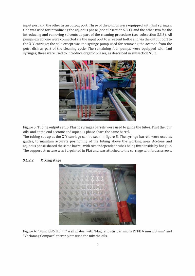
S.1.2.2 Mixingstage
Figure6:“NuncU960.5ml”wellplates,with‘MagneticstirbarmicroPTFE6mmx3mm”and
“VariomagCompact”stirrerplateusedthemixtheoils.

7
Therobotusedastandard96‐wellplate(seefigure6);eachwellhaditsownminiaturemagnetic
stirrerbarandtheentireplatewasmountedoverastirrerplate.Thisdesignwaschosensothat
multipleexperimentscouldbeconcludedbeforemanualinterventionwasnecessarytocleanthe
mixingarea.
S.1.2.3 Carriage‐mountedsyringes
Asshowninfigure7,anautomaticsyringewasdesignedtobeusedwiththeX‐Ycarriage.The
casing and structurewas 3d‐printed fromPLA. Independent crankmechanismswere used to
actuatetheplungerofthesyringeandtolowerandraisethesyringe.Theseconsistedofthedefault
servomotorarmanda3d‐printedpiece, joinedvia steelpins.Thecrankwasalignedwith the
centreofthesyringeitselftoavoidunwantedlateraltorque.Smalldiametersteelrodsandteflon
linearbearingswereusedtomitigaterotationawayfromandtowardstheservo.
Figure7:Automatedsyringeprototype.Theplungerwasactuatedusinga9gservomotor.Guide
rodswereusedtoavoidbending.

8
Figure8:Syringeattachedtoneedleandliftingmechanism.Thesameliftingmechanismwasused
toraiseandloweraplasticneedletoremoveliquidfromthePetridish
Thesyringeswerefittedwithametalneedle‐tip,asshowninfigure8.Themechanismtoraiseand
lowerthesyringe,viaacrank,canalsobeseeninthisfigure.Ontherightoffigure8,thesame
mechanismcanbeseentobeactuatinganunactuatedsyringe.Thissyringehashaditsplunger
removedandisinsteadfittedwithapieceofplastictubing,whichconnectsittoasyringepumps.
Thissyringewasusedtoremovesolvents fromthePetridishduringacleaningcycle.For this
reason,theneedletapertipwascut,toeffectalargerabsorptiondiameter.WhilstDropBotonlyused one of each syringe type, itwould be possible to expand the robot by adding additional
syringestothecarriage.
S.1.3 Electronics
Theelectronicscanbedividedintothreegroups.Onegroupcontrolsthemovementoftherobot
alongtheXandYaxes,anothergroupcontrolstheservomotorswhichactuatethesyringes,and
athirdgroupcontrolthepumps.

9
S.1.3.1 Axiscontrol
Figure9:ArduinoMegaPCBshieldwithdirectcontroloutputsto2steppermotorsandbreakout
headertotheservodaughter‐board.
Themovement along the X and Y axes was performed using a stripped down version of the
electronicsusedbyaRepRap3Dprinter,whereonlythepartsrequiredbytheXandYmovement
werekept:anArduinoMega[2]boardand“A4988StepperMotorDriverCarrier”.APCBshield
was designed (see Figure 9), which interfaced the Arduino board to the motor drivers and
providedconnectorsforthemotorstothedrivers.Inaddition,connectionswereprovidedfortwo
end‐stops,eachassignedtoaparticularaxis, forhomingpurposes.Eachstepperdriverhad16
pins,butonly3ofthemwereneededtocontrolthemotor:enable,stepanddirection,withthe
otherpinsbeingconnectedtohigh(5V),low(GND),12Vortothemotoritself.Theboardtherefore
usedonlyeightoutputs(theend‐stopsusedtwooutputs)fromtheArduinodirectlyandinterfaced
the remainder of digital connectors, and a power supply, to a header output for the servo
daughterboard.TheattachmentbetweentheArduinoboardandthePCBshieldcanbeseenon
Figure10.
Figure10:ArduinoMegaboardwiththePCBshielddescribedonFigure9attached.

10
S.1.3.2 Carriagecontrol
Theheaderinputtotheservodaughter‐board(Figure11)consistedoftwentypins,connectedto
theArduinoviaaribboncabletothebypassontheXYdriverboard.Theservoboarditselfwas
mountedontheX‐Ycarriageinordertoprovidebothpowerandcontroltothesyringe‐actuation
servomotors.Each servomotor tookpower froma commonsupplyandwere connected to a
commonground,withtheonlyindividualconnectionbeingasinglePWMdatapintotheArduino.
The servo daughter‐board was therefore able to service 20 unique servo motors, of which
maximumfourwereusedinpractice.
S.1.3.3 Pumpcontrol
ThepumpsmentionedinsectionS.1.2.1werefaultyonlyinthefunctionoftheirlogicboards;the
mechanicalcomponentsandmotorswerefullyoper‐
Figure11:PCBdesignedtomapthedigitalpinsfromtheArduinoboardintoservomotorsockets.
Itworkedforboth3.3Vand5Vservomotors.

11
Figure12:TricontinentpumpbeingusedbyattachingitsmotorstothedesignedPCBshield.
Figure13:EachpumpwasassignedauniquePCB,withonedrivercontrollingeachmotor.Each
driverwascontrolledbyanArduinoboardcommontoallpumpsbutseparatefromtheX‐Y/servo
Arduino.

12
ational. As motion was provided by two stepper motors, from the NEMA family, these were
thereforecompatiblewiththeshielddevelopedfortheX‐Yaxiscontrol(SectionS.1.3.1).Itwas
therefore possible to re‐use the mechanical components of these syringe pumps by the
replacementoftheirelectronicswithcustomPCBs(Figure12).Sinceeachboardcontrolledtwo
steppermotors,asingleboardwasassignedtoeachpumps(Figure13).AsecondArduinowas
assignedentirelytopumpcontrol,inadditiontoasecondpower‐supplyassignedonlytopump
motors.
S.1.4BillofMaterials
• The framewas built using Bosch‐Wrexroth 20x20mm aluminium strut profile, fastened
togetherusingcustom,3d‐printedPLA1pieces.
• ThemotorsusedwereNEMA214fortheY‐axisandtwoNEMA17sfortheX‐axis.
• ThelinearmotionmechanicswerederivedfromtheRepRapprinter,usingabelt(Timing
beltT2.5x6mm)andpulley(T2.5pulley,5mmbore)systemconnectedtothemotors
• Round‐profilehardened‐steelbar (8h7, chromeplated)and roundprofile linearbearings
(LME8UU)wereusedtoachievesmoothlinearmotion.
• Thesyringepumpsmodifiedandusedwere“TriContinentC‐Series”•“IDEXHealthScience
PEEK1/8”” tubingwasusedtoconnectthosepumpsused introduceorremovecleaning
solventto/fromthepetridisharena.
• “IDEXHealthScienceFEPOra1/16x0.20””wasusedtocarryorganicphasesfromreagent
bottlestosyringepumpsandfromsyringepumpstotheX‐YCarriage.
• The syringe used to direct the tubing from the syringepumps at the carriage the “1ml
NORM‐JECT”.
• Thesesyringeswerefittedwith“WellerKDS16TN25NeedleTaperTip16G”.
• Thesyringeused in the servo‐actuatedsyringeswasa “Hamilton710LT100μL”. •The
needlesusedwere“WellerKDS2012PDispensingNeedleGA20ID0.66MM”.
• Thesyringewasraisedandloweredbya“NewPowerXL‐3.7”servomotor.
• Theplungerwasactuatedwitha“9gservomotor”.Inthisspecificcase,a“TowerProMicro
Servo9gSG90”.
• Themotorarmusedwasthedefaultarm,whichshippedwiththeservomotor.
1Polylacticacid.
2NationalElectricalManufactersAssociation.http://www.nema.org

13
• Thewellplateusedwas“NuncU96PP0.5ml”.
• Insideeverywell,a“MagneticstirbarmicroPTFE6mmx3mm”wasusedtoprovideliquid
turbulence.
• Belowthewellplate,wasasingle“VariomagCompact”stirrerplate,usedtoturnthestirrer
bars.
S.2 Software
Figure14:Softwarearchitectureshowingdistributionofworkflowactorsandactuatorsandtheir
distributionintosoftwarepackages.
A hierarchical/deliberative paradigm was followed when designing the control software.
SoftwarecomponentsresidentonthehostcomputerwasprogrammedentirelyinPython,whilst
software components on the Arduinos (referred to henceforth as the firmware) were
programmedinC++.Softwarewasdividedintothreeconceptualmodules:planning,acting,andsensing.Figure14representsthestructureofthishierarchy;data‐flowoccursinaniterativeloop(shown).
The artificial intelligence (AI) component is responsible for coordinating the overarching
experimentalplan,selectingdropletformulationsbasedonprior(ifany)dataandpassingthese
formulae on to the next component. Thus the AI acts as globally, with overview of an entire
experimentalseries,andtheRC,FWandCVcomponentshavepurviewonlyofsingleexperiments.
Theroboticscontroller(RC)takestheseformulaeasinputand,actingasaninterfacebetweenthe
AIandthephysicalrobot, transformsthesenumericalrecipes intoaG‐coderepresentation.G‐
codeisastandardizedschedulinglanguage[3]usedintheautomationindustrytoplanmechanical
operations(seesubsectionS.2.2formoredetails).
Thefirmware(FW)consistsofsoftwareresidentontheArduinoboard.Itconvertsthesymbolic
G‐code representation into a series of experimental operations, instantiated as a sequence of
analogueanddigitalsignalssenttothemechanicalpartsthroughtheArduinoboards.

14
Thecomputervision(CV)componentinterfaceswiththecameraandconvertsrawimagedata,
throughanalgorithmicimage‐processingpipeline,intoquantitative‐numericalfitnessdata,which
isthenreturnedtotheAI.
Figure 15: UML diagram describing the softwarework‐flow and communication between the
diversesoftwarecomponents.
A multiprocessing software architecture was chosen to make maximum usage of time and
resources, and to ease development by modularizing the software. Software interprocess
communication was used between modules running on the host computer, whilst USB‐serial
protocolswereusedtocommunicatebetweenthesoftwareandfirmware.Thecommunication
layersbetweenthevariouscomponentsisoutlinedinfigure15;interestedreadersshouldconsult
theprovidedsource‐codeforfurtherdetails.
S.2.1 RobotController
Therobotcontrollerfunctionstotranslateexperimentalproceduresformahigh‐leveldescription
intoaG‐coderepresentation.TheG‐codecanbeconsideredasanintermediatelayerbetweenthe
description of a recipe and the digital actuation, effected by the electronics. By using this
translation pipeline, a number of expert‐written modules could be leveraged, significantly
reducingdevelopmentcostsandtime.ThecorecomponentoftheRCisthePrintRun[4]library,
developed for controlling RepRap printers (via G‐code) and and which constitutes the most
popular choice of library for this purpose. As this central library is written in the Python
programming language[5], this language was used for the entire development of this layer.
PrintRuncommunicateswiththeArduino‐basedFirmwareviaaUSBemulated‐serialconnection,
facilitatedbythepySeriallibraryonthehostcomputer[6].

15
The RC’s interface to exterior code was encapsulated within a library called “RobotCtl”. This
library contains functions which relate to the fixed set of modular lab operations (e.g. “form
droplet”or“cleanpetridish”)requiredtoperformallexperiments.Theinterfacefunctionedto
convertasequenceoftheseoperationsintoasequenceofG‐codeinstructions.Therobotcould
movethesyringestoanypositionaroundXorYwithaprecisionof0.1mmandthisprecisionwas
accountedforintheconversion.SincethereweremultiplecomponentsontheX‐Ycarriage,the
relativedistancebetween thesecomponentswashardcodedandused tomodify the finalX‐Y
positionwhenonespecificapparatuswasselected.Incontrasttotheoperationalmodeofa3d‐
printer,whichproducestheentirebatchofG‐codefroma3dmodelinonerun,theRCrunsin
onlinemode,compilingoperationsintoG‐codeastheyarereceived.Thismodeofoperationisa
necessity,duetotheiterativenatureoftheprocedures,wherebyfutureoperationsareunknown
until data from present operations have been processed. The Gcode produced in real‐time is
communicatedtotherobotviathePrintRuncore.
S.2.2 Firmware
Thefirmwarelayerisdirectlyresponsiblefortheactuationofmechanicalparts.Thefirmwarewas
writtenspecificallyforthetargetArduinoboards,hencetheArduinodevelopmentenvironment
wasusedforthislayer.ThenativelanguageofthisenvironmentisC++;therefore,thiswasthe
languageusedtodevelopthefirmwarelayer.
Code DescriptionPX SelectspumpX.X
MY SelectsmotorY.Y
DZ Selectsplungerdirection.Z
SA Setsspeed.Aisthenumberofmsofwaitbetweensteps
EB Setsnumberofsteps.Pumpsusedarelimitedtoa
maximumof50000steps
Table1:“PXMYDZSAEB”ExampleofG‐codeoperationsoutputbytherobotcontroller.
ThereweretwoseparateArduinoboards,onetocontroltheX‐Ycarriage(subsectionS.1.1.5)and
onetocontrolthefluidplatform(subsectionS.1.1.6)AswiththeRClayer,thecarriagefirmware
was built on top of extant 3d‐printermodules. In this case, the firmware core used was the
Sprinterpackage[7],commonlyusedwithReprap3Dprinters.FunctionalitywithregardstoZ‐
axismovement,temperaturecontrolandextrusionofthermoplasticwasremovedfromthecode‐
base.Initsstead,functionalitywasaddedforcontrolofthesyringes(SeesubsectionS.1.2.3),via
the servo library provided by Arduino[8]. The modified Sprinter firmware was therefore
capabilityofX‐Ymotion,abletoactuateallservo‐motorsandsynchronizetheseactuationswith
theRCcomponent,viathereceiptandparsingofG‐codeinstructions.
Thefluidplatformfirmwarewasdevelopeddenovo.Eachpumpcontainedtwocomponents:Athree‐wayvalveandlead‐screwactuatedplunger.Bothofthesecomponentssourcedmotiveforce
fromaNEMAsteppermotor.Thesemotorswerecontrolled,aswithothermotorsontherobot,
viaan“A4988StepperMotorDriver”.AG‐codeinterfacewasadded,withnewsymbolsforpump
movement(Table1).VerylittlesanitycheckingwasperformedandsotheRCwasrelieduponfor
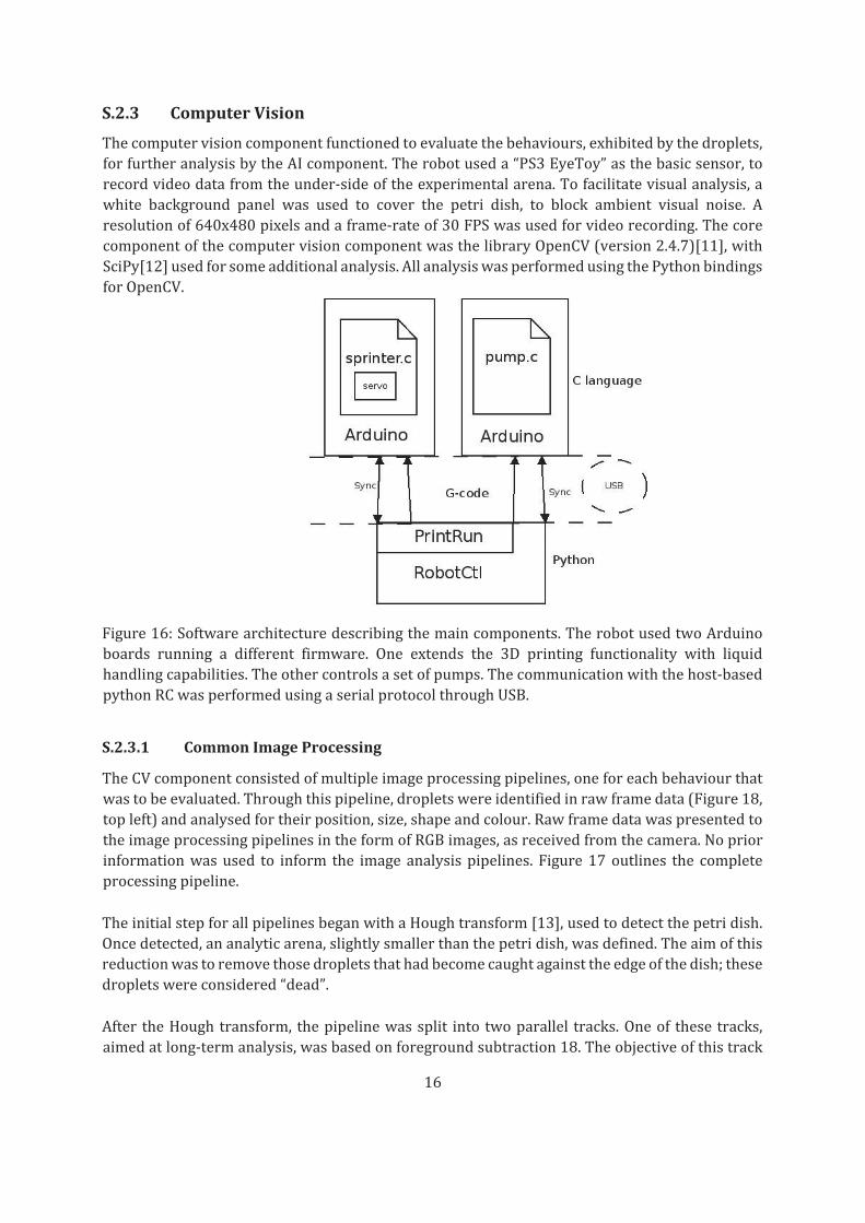
coherentoperation.Figure16outlinesthecomponentsdescribed.
16
S.2.3 ComputerVision
Thecomputervisioncomponentfunctionedtoevaluatethebehaviours,exhibitedbythedroplets,
forfurtheranalysisbytheAIcomponent.Therobotuseda“PS3EyeToy”asthebasicsensor,to
recordvideodatafromtheunder‐sideoftheexperimentalarena.Tofacilitatevisualanalysis,a
white background panel was used to cover the petri dish, to block ambient visual noise. A
resolutionof640x480pixelsandaframe‐rateof30FPSwasusedforvideorecording.Thecore
componentofthecomputervisioncomponentwasthelibraryOpenCV(version2.4.7)[11],with
SciPy[12]usedforsomeadditionalanalysis.AllanalysiswasperformedusingthePythonbindings
forOpenCV.
Figure16:Softwarearchitecturedescribingthemaincomponents.TherobotusedtwoArduino
boards running a different firmware. One extends the 3D printing functionality with liquid
handlingcapabilities.Theothercontrolsasetofpumps.Thecommunicationwiththehost‐based
pythonRCwasperformedusingaserialprotocolthroughUSB.
S.2.3.1 CommonImageProcessing
TheCVcomponentconsistedofmultipleimageprocessingpipelines,oneforeachbehaviourthat
wastobeevaluated.Throughthispipeline,dropletswereidentifiedinrawframedata(Figure18,
topleft)andanalysedfortheirposition,size,shapeandcolour.Rawframedatawaspresentedto
theimageprocessingpipelinesintheformofRGBimages,asreceivedfromthecamera.Noprior
informationwasused to inform the image analysispipelines. Figure17outlines the complete
processingpipeline.
TheinitialstepforallpipelinesbeganwithaHoughtransform[13],usedtodetectthepetridish.
Oncedetected,ananalyticarena,slightlysmallerthanthepetridish,wasdefined.Theaimofthis
reductionwastoremovethosedropletsthathadbecomecaughtagainsttheedgeofthedish;these
dropletswereconsidered“dead”.
After theHoughtransform, thepipelinewassplit into twoparallel tracks.Oneof thesetracks,
aimedatlong‐termanalysis,wasbasedonforegroundsubtraction18.Theobjectiveofthistrack

17
was thediscovery,andremoval,ofambientbackground fromthechemicalcomponentsof the
experiment(droplets).Becauseawhitebackgroundwasused,onlythearena,withaqueousphase
present,anddropletswerepresent.Thesecondtrackwastargetedatanalysisofearlyframesand
wasbasedonachainofimageprocessingoperations.Theobjectiveoftheimageprocessingtrack
wasthediscoveryofclosedstructures,whichcorrespondedtodroplets.Thesestructurescould
haveanyshape,aslongastheycouldberepresentedbyaconnectedcomponent.
Figure17:Schemeoutliningthepipelineofthedifferenttechniquesandalgorithmsinvolvedin
thedropletdetection.
The imageprocessing trackbeganwithanRGB‐to‐greyblurringoperation, applied to remove
noise.ThiswasfollowedbytheapplicationoftheCannyedgedetectionalgorithm[14],resulting
inanedgemap(Figure18,topright).Ascontoursmaybemissingpixels(ascanbeseeninfigure
18),adilationoperationwasappliedtofillthesegaps.Thiswasfollowedbya“flowfill”operation,
withtheoriginatpixel(0,0)(Figure18,bottomright).Theresultofthisoperationwastheremoval
of any non‐closed structure. The previously calculated Hough transformwas then applied, to
define the operational arena (Figure 18, bottom right). The next step in the pipelinewas the
applicationofadistancetransform,toremovenoiseandtodisconnectdropletsthatmayhave
beenartificiallyconnectedintoonestructureasaresultofthedilationoperation(Figure19,top
right).ThesefinalconnectedcomponentswerelabelledusingSciPy;thelabelsandthebordersof
theconnectedcomponentsweresenttoawatershedalgorithm[15],torecovertheoriginalsizeof
thedroplets(Figure19,bottomleft).Thisconcludedtheimage‐processingtrackoftheparallelCV.
The foreground reduction algorithm used a mixture of Gaussians[16]. The default OpenCV
parameterswereusedforfittingthemixturemodel,withlearningratesetto0.05.Theresultof
themixturemodelwasaforeground(droplets)withbackgroundinformationremoved.
Thetwoparalleltracksresultedeachinabinaryimage,wherepixelswereeither‘on’(pixelispart
ofadroplet)or‘off’(nodroplet).Thesetwoimageswerecombined,usingaboolean“or”operation
togivedefinitivedroplet‐onlyimages.Thecontourswerethendiscoveredonthiscombinedimage
(Figure19,bottomright).Withthiscontourmap,thearea,size,shape,colourandcentreofthe
dropletscouldbecalculated.Thesedatawerethenpassedontothefitness‐specificcomponents
oftheimage‐processingpipeline.

18
Figure18:Dropletdetection,imageprocessingpipeline.Topleft:Rawframe.TopRight:Canny
edgedetection.BottomLeft:Dilatemorphooperation.BottomRight:Floodfilloperation,seedat
pixel0,0.
S.2.3.2 Tracking
Acommonwaytotrackobjectsistouseafilter,liketheKalmanfilter[9]oraparticlefilter[10].
Sincethecameraproduced30FPS,overlappingconsecutiveframestotrackdropletsovertime
wasenoughconsideringthesizeofadropletandhowmuchitcouldmovebetweenframes.
Givenadropletdtinframet,andasetofdropletsDt−1inframet−1,asetofcandidatesCt−1was
builtasthedropletsinDt−1whosecenterwasinsideanareadefinedasacirclewith30pixelsof
radiusarounddt.ThebestcandidateinCt−1waschosenasitwasthenearestdroplettodtusingthe
Euclideandistance. If therewerenodroplets inside thisarea,orall thedropletswerealready
assignedtoanotherdroplet,thisdropletwasconsiderednew.

19
Figure19:Dropletdetection,imageprocessingpipeline.Topleft:Houghtransform,dishdetection.
TopRight:Distancetransform.BottomLeft:Watershedalgorithm.BottomRight:Finalresult.Blue
circlemarksthedishdetection,redcirclerepresentsthearena.
S.2.3.3 ExperimentalDataGeneration
For each experiment, a data structure describing the positions of the droplets over timewas
produced.Thisdatawasusedinordertorateanexperimentbasedondifferentfactors.During
this research, the behaviours analysed in this way were “division”, “movement” and
“directionality”.
S.2.3.4 Division
Everyexperimentbeganwiththerobotplacingdropletsintheaqueousmedium.Dependingon
thechemistry,thedropletscouldsplitassoonastheyinterfacedwiththeaqueousphase,butthe
robotmadeexactlyfourinjections.
Divisionwasdefinedasthenumberofdropletsaliveattheendoftheexperiment.Weconsidered
asviableanydropletwithanareagreaterthan15pixels.Theexperimentaimedtofinddroplet
recipesthatwoulddivideinacontrolledfashion,producingviableoffspringratherthandisparate
fragments.
S.2.3.5 Movement
Givenadropletd,itsmovementwasdefinedastheEuclideandistancedescribedbyitstranslationbetweenframestandt+1.Thistranslationwasdescribedinpixelsasthefundamentalunitsofdistance.

20
Sincebetweenapairofframestherecanbeseveraldropletsmoving,thetotalsumofdistances
describedbyallthedropletswasdividedbetweenthenumberofdroplets,obtainingtheaverage
distancetranslatedperdroplet.Everyexperimentranfor1minute,containingafewthousandof
frames.The averagedistanceperdropletwas calculated for everypair of frames, its quantity
summed, and then divided by the total number of frames, in order to obtain the average
translationdescribedperdropletperframe.
Themovement‐derivedfitnessisthengivenby
(1)
whereNisthetotalnumberofframesinthevideosequence,Misthetotalnumberofdropletsobservedandwhere(xi,t,yi,t)aretheEuclideancoordinatesofdropletionframet
S.2.3.6 Directionality
Givenadropletdinframet,t+1andt+2,itspositionforeachframeintheXYplaneisdenotedbythepointsA,BandC.Twovectorsweredefined: and .
Bydirectionalityofadropletitismeanttheanglebetweenvandwwhichrepresentsthechangeofdirectiononadropletmovingpattern.Lowvaluesmaptodropletswhichmoveinstraightlines,
middlevaluestodropletswhichdescribecurvesandhighvaluesdropletsthatvibrateorwobble.
Invertingthedotproductformula:
(2)
Theangleisobtained:
(3)
Foreachexperiment,theangularrotation,perdroplet,perframewasgivenwasusedasthe
directionalfitness,asgivenby
(4)
S.2.4 ArtificialIntelligence
For each behaviour to be tested, three Genetic Algorithm (GA) runswere used. Each GA run
performed21generations,withafixed‐populationsizeof25individualsand15individualsbeing
propagated fromthepreviousgeneration, fora totalof225recipes.Eachrecipewasrepeated
threetimes,andtheminimumbetweenthemeanandtheaverageof these3experimentswas
returned.Eachexperimentgeneratedfourdroplets.

21
AcompletetestrantheGA3times,thereforeintotalitgenerated675recipes.Eachrecipewasrepeated3times,foratotalof2025experiments.Eachexperimentgenerated4droplets,foratotalof8100droplets.
Individualswerefixed‐lengthgenomesof4 floating‐pointnumbers(i.e.Quantitativetrait loci).
TheGAusedaper‐locusprobabilityofmutation(resulting inapoisson‐distributednumberof
mutations per individual). For each locus selected for mutation, a normal‐distributed noise
function,withameanof0andanSDof0.1wasadditivelyapplied.Eachchildwasalwaystheproductof a single crossover recombinationbetween twodistinctparents,with the crossover
beinguniformlydistributedalongthegenomeandthesamegeneticlocationbeingusedforeach
parent. Individuals were birthed with parents being selected, without replacement, from the
extantpoolwithprobabilityproportionaltothefitness(tothepowerofsomeparameter).After
birthingandfitnessmeasurement,thepopulationwasculledtoafixedsize,withindividualsbeing
chosen fordeathwithprobability inverselyproportional to the fitness (to thepower of some
selectivepressureparameter).
Parameter Value
Generations 21
Genomelength 4
Populationsize 25
Carry‐overs 15
Per‐locusmutationrate 0.3
QTLmutation(SD) 0.1
Selectivepressure 1
Table2:ParametersusedtogenerateallGA‐deriveddatapresentedinthispaper.
S.3 Chemistry
OilsandsurfactantswerepurchasedfromSigma‐Aldrichandusedasreceived,unlessotherwise
stated.Allexperimentswereperformedat22degreesCelsius.
S.3.1 Preparationofaqueousphase
Tetradecyltrimethylammoniumbromide(TTAB)(6.73g,20.0mmol)wasdissolved indistilled
water(ca600mL),adjustedtopH13.00with5MNaOHsolutionandmadeupto1Ltogivea20mMsolutionatpH13.00.
S.3.2 Preparationofoils
Theoils(1‐octanol,octanoicacid,dodecane,1‐pentanolanddiethylphthalate)werepreparedin
200mLaliquotsinreagentbottles.Eachoilwasdyedwith0.25mg/mLSudanIIIandvortexedto
mix.

22
S.3.3 Cleaningcycle
Aftereachexperiment,acetone(ca3mL)waspumpedintothepetridishtodissolveremainingoildropletsandthemixturewasaspiratedfromthedishtothewastecontainer.Thedishwasthen
washedwithacetone(2x3mL)andaqueousphase(2x3mL)Lessthoroughcleaningcycleswere
oftentoleavetraceresidues,whichinterferedwithsubsequentexperiments.
S.4 Methods
A fully automated liquidhandling robot capable of producingdroplets in aPetri dishwith an
aqueoussub‐phasewasconstructed.TherobotwasbaseduponaRepRap3Dprinterarchitecture
withawebcamforvideorecording/imageanalysis.

23
Thedropletformulationsareproducedinwell‐plates(96‐wellformat)whereeachwellisstirred
withamagneticstirrerbar.Thedropletformulationsarebaseduponthefollowingreagents((1‐
octanol,1‐pentanol,diethylphthalate(DEP),dodecaneanddilutionsofoctanoicacidinoneofthe
otheroils(typically20Theformulationsweredeliveredfromthecomputercontrolintheformof
fournumbers,whichrepresentedtheproportionofeachoil;thereforethetotalsummedto“1.0”.

24
Thetotalvolumeoftheoilsplaceinawellwas360μL.Thespecificquantityforeachoilwasthisvolumemultipliedbytheirrelativeproportion.
Oncethemixingwascompleted,threeexperimentswereconductedfromthefinalformulation.
Foreachexperiment,80μLofoilwereabsorbedusingthesyringe.Ofthisvolume,four5μLoildropletsarethenplacedintheaqueousphase(20mMaqueoustetradecyltrimethylammonium
bromide(TTAB),adjustedtopH13.00with5MNaOHsolution).Thesepositionswereconsistent
betweenexperiments,withpre‐programmedX‐Ycoordinates.Theneedlewaslaidjustabovethe
aqueousphaseandthedropletswerereleasedto thesurfaceof the liquid.Onceadropletwas
outsidetheneedle,thesyringewasmoveduptoitsdefaultposition.Thismovementbrokethe
tensionbetweenthedropletandtheneedle,depositingthedropletovertheaqueousphase.This
processissummarisedinFigure20.
A video of the resulting droplet behaviourwas then recorded from beneath the dish using a
cameraataresolutionof640x480pixelsat60fpsfrombelowaftercoveringthetopofthePetri
dishwithawhitebackgroundfor60seconds.Aftertheexperimenttheentirecontentsofthedish
areautomaticallyremoved,cleanedwiththreewashesofacetonefollowingwiththreewashesof
aqueousphase.Duringtheacetonewash,thesyringeiscleanedalsowithacetone.Afteracomplete
generationhasconcluded,theevolutionaryalgorithmquantifiesthefitnessoftheformulations
andcalculatesthenextsetofreagentvolumes.Imageanalysisofthedropletbehaviouragainstthe
fitnessfunctionprovidesthenextsetofinputsfortheevolutionaryalgorithm.
Our four component system comprises 1‐Octanol, Diethyl‐phthalate, 1Pentanol, and either
OctanoicacidorDodecaneasthefourthingredient.Movementof1‐pentanoldropletsisdescribed
in the literature [30], and a range of other mid‐to‐long chain alcohols were tested using
automation to explore a range of solubilities. Diethyl phthalate is known to form stable
droplets[31].Dodecanewaschosenasanextremelynon‐polaroilwithlowdensityandviscosity.
OctanoicacidwasexploredasitisdeprotonatedathighpHtoformananionicsurfactant.
Oncetheexperimentwasconcluded,thesyringepumpswereusedtopumpacetoneandaqueous
phaseintothePetridishandthentoremovethesolvatedwaste.First,threewashesofacetone
wereperformed:4ml,4mland3ml.Duringthefirsttwoofthesewashes,theneedlewasdropped
intotheacetone,andtheplungerwasactuatedtoabsorbandreleaseacetone,cleaningtheneedle
andsyringe.
Figure 20: Outline of the droplet generation. First the aqueous phase is placed, and then the
dropletsaredroppedoverit.

25
Afterwashingwithacetone,threewasheswithaqueousphasewereperformed,with1.5ml,1.5
mland1ml.Theobjectiveoftheaqueousphasewashwastoremovetheremainsofacetonefrom
the petri dish so that it would not interfere with subsequent experiments. This process is
summarizedinfigure21.
Figure21:Atfirst,threewasheswithacetonewereperformed.Betweenthefirstandsecond,and
thesecondandthird,thesyringeisdippedintotheacetone,andtheplungeractuated,cleaning
theneedle,barrelandplunger.The three followingaqueousphasewasheswereperformedto
removetheremainsofacetone.
S.5 Analysis
S.5.1 ProcessingofFitnessLandscapes
The fitness landscapes seen in Figure 6 in themain textwere produced through amulti‐step
analyticalpipeline.TheresultsfromtheGAwerefirstcollatedandpassedthrougharadialbasis
functionkernelridgeregressiontoproduceamodel.Thismodelwasthenqueriedthroughagrid
searchalongeachfaceoftheparameter‐spacesimplextoestimatethefitnessateachlocation.
S.5.1.1 KernelRidgeRegression
GeneralLinearRegression(GLR)performsmodelfittingbyminimizingthesum‐of‐squareserror
overaspaceoflinearcoefficients,inanequationoftheform
(5)
withthesum‐of‐squareserrorbeinggivenfor
pointsas. (6)
Ridge‐regression, also known as Tikhonov regularisation[24], is a commonly usedmethod of
regularizationofill‐posedproblems.Thisformofregressionaugmentstheminimizationwitha
weightedpenaltyonthesizeofthecoefficientvectorφ:

26
(7)
Kernel ridge‐regression is a re‐formulation of ridge‐regression, used in situation where the
numberofdimensionsexceedsthenumberofdata‐points.Equation5issubstitutedby
(8)
Withequation7takingtheequivalentsubstitution:
(9)
Animportantpropertyofthisreformulationisthat itrequiresthecalculationofadot‐product
between each input vector and every other. These dot‐products can be collated in the Gram
matrix:
G=XXT (10)
However,thedot‐productdoesnotneedtobecomputedininputspace.Higherpredictivitycan
oftenbeobtainedbytransformingtheinputvectorsintoahigher‐dimensionalspace,knownas
”featurespace”:
zi=f(xi) (11)
theGrammatrixG isthenreplacedbythekernelmatrixK,whoseentriesaregivenby
. (12)
Rather than calculating the dot products through an explicit mapping from input space into
feature space, it isusuallyquicker tousean implicit feature‐space innerproductg, calculateddirectlyontheinputvectors:
Kij=g(xi,xj) (13)
Thefunctiongisthenknownasthe”kernelfunction”anditsuse,withassociatedimprovementsincomputationalspeed,isoftenreferredtoasthe”kerneltrick”.
S.5.1.2 RadialBasisFunction
Thekernelfunctionthatweapplytoextendthesampledpointsintoasmoothfitnesslandscapeis
theGaussianKernel.ThiskernelfunctionfallsintothebroadercategoryofRadialBasisFunctions
(RBFs), whose members are defined by being real‐valued function that depend only on the
distance,ininputspace,betweentheinputvectors.Distanceisheredefinedbetweenpointsiandjas . (14)
TheGaussianRBFthendefinesthekernelfunctionbetweentwopointsiandjas
. (15)
Whereσisaproblem‐specificparameter,roughlyequivalenttothestandarddeviationoftheGaussian probability distribution. One peculiar property of the Gaussian kernel function, not
sharedbyotherRBFs, is its implicitmappingof the inputvectors intoan infinitedimensioned
φ

27
feature space. This property arises from the expansion of the exponential term, here
demonstratedforasingle‐dimensioninputvector:
(16)
(17)
Asaresult,whereasotherkernelfunctionscanbeusedtoderiveasetoffeaturespacecoefficients,
theGaussianRBFrequiresthatthekernelfunctionbeevaluatedforeveryNtrainingvectorwithanewvector,forapredictiontobemadeforthatvector:
(18)
S.5.1.3 CompleteLandscapes
Threereducedfitnesslandscapesareshowninthemaintextinfigure6.Eachofthesesubfigures
showsathree‐dimensional“facet”of the four‐dimensionalspaceofoilcomposition.Each facet
waschosensothattheglobalmaximum, foreachenvironment,wouldbeshown, ineachcase.
However,aseachfacetisderivedbyholdingoneoftheoilproportionsatzero,therearethree
otherfacetsperenvironment.Allfacetsforthethreeenvironmentsarethereforeshownbelow.
Figure22:Fitnesslandscapesfortheenvironmentsdivision(Ai‐iv),motility(Bi‐iv)andvibration(Ci‐iv. In eachplot, three substances are displayed as the plot title. The fourth substance canthereforebeassumedtobeheldataconstantzero.Theprojectionusedisequivalenttotheternary
plots shown in themain text. Each axis shows theproportion of a substance (indicated). The
proportionofthethirdsubstance(Z)iscalculatedasZ=1−X−Y.Thenumericalindicationsshowthelocationoffitnesspeaks.Indivisionandvibrationtwomajorfitnesspeakswerediscovered.

28
Minorfitnesspeaksarenotindicated.Thescalebarcorrespondstothefitnessfunctionsforeach
environmentandarenotcomparablebetweenenvironments.
Figure22showsfourfitnesslandscapesperenvironment,displayingagreaterproportionofthe
analysisthanthatfoundinthemain‐text.As“true”representationofthedataconsistsofasolid
four‐dimensionalsimplex,graphicalrepresentationisinherentlydifficult.Theauthorstherefore
optedtodisplayonthefacesofthissimplex.Thiswasconsideredareasonableapproximationas,
foreachenvironment,theglobalmaximumwasfoundononeofthesefacesandnotinternally.
Indeed, fordivisionandvibrationenvironments,thelargerofthetwomajorfitnesspeakswas
foundonanedgebetweentwofaces(atwo‐substancecomposition).Thesemaximacantherefore
beseen,ontwofaces,fordivisioninAiiiandAiv(7.777)andforvibrationinCiiandCiii(7.188).Numeroussub‐optimallocalmaximaarealsodiscoveredbytheanalysisinallenvironmentsand
areexploredinsubsectionS.5.1.4.
S.5.1.4 Catchment
Inanevolutionaryfitnesslandscape,multi‐modalitycorrespondstotheconceptoffitnessislands[27].Suchafeatureisdefinedasbeingthatvolumesurroundingalocal(ortheglobal)maximum,
suchthatforanypointwithinthatvolume,consistent,upwardprogressalongthegradientwill
convergeatthatspecificmaximum.
Toanalysethenumberandboundariesofthefitnesslandscapesthatunderlytheexperimental
evolutioncomponentofthismanuscript,adiscoveryalgorithmwasrunonthefitnesshyperplanes
derived through the kernel modelling. The hyperplanes were represented as 4 301 × 301
quantizedlattices,asplottedinfigure4inthemaintext.Foreachuniquemaximum,anactiveset
wasmaintained,startingwithasinglelocationatthatmaximum.Foreachlocationintheactive‐
set,alleightsurrounding,quantizedlocationsweretested,suchthatforeachlocationtested,the
8 locations around that locationwere tested, to discoverwhich of them corresponded to theneighbouring maximum. For each location whose neighbouring maximum was the current
locationfromtheactive‐set,thatlocationwasmarkedasbelongingtothecurrentfitnessisland
andthenaddedtotheactive‐setforanalysisofitsownneighbourhood.Itwassimpletoallowthis
search to extend over the boundaries of one hyperplane to another hyperplane, where the
locationswereequivalent(i.e.whereoneofthecomponentswas0).
Theresultsofthisalgorithmarepresentedinfigure23.Foreachofthethreelandscapes,exactly
five fitness islandswereobserved,althoughtheremaybe fitness islands, in the interiorof the
fitnessspace,notrevealedbythesearchacrosstheexteriorhyperplanes.Thereisinsufficientdata
tospecifywhethertheconsistencyoftheoccurrenceoffiveislandsperlandscapeisaproductof
thedimensionalityoracoincidentalartefact.
S.5.2 EvolutionaryTrajectories
Statistical analyses were carried out on the evolutionary trajectory of each of the three
optimizationexperiments.Therawfitnessdistributions,asafunctionofgenerationareshownin
figure24.

29
Figure23:Fitnessislandmapderivedfromthekernelanalysisforthefitnesslandscapesdivision
(Ai‐iv), motility (Bi‐iv) and vibration (Ci‐iv). Each colour (Red, yellow, green, blue, purple)corresponds toastable fitness island(coloursstated insortedorderof island‐maximumfrom
highesttolowest[i.e.redisthefittestislandandpurpletheleastfit]).Fiveislandswereobserved
ineachlandscape,althoughitisunknowniffurtherislandsarepresentintheinteriorofthefull
simplex.
It isstatedintheintroductionthatthefinalpopulationofdroplets, inallcases,showenriched
fitness compared to the initial populations. This analysis was performed by comparison of
generation 1 with generation 21. It is common, in biological scenarios, to consider the fitter
membersofapopulation,ratherthantheaverage,sincethesewillpropagate.P‐values forthis
analysiswerethereforeconductedbycomparingonlythetophalf(fitnessgreaterthanmedian)
of each generation. This resulted in 38 individuals per generation (all three repeats were
amalgamated).Analysis‐of‐Variancewasthenperformedwithfitnessasafunctionofgeneration
(21or1)andissummarizedintable4.
Fromtheresultspresentedinfigure24,itnotvisuallyobviouswhetherpopulationfitnessshows
improvementduringthelatterhalfofeachrun.Todeterminewhetherthiswasthecaseornot,
thesameanalysisasabovewasrepeated,butwithgeneration21comparedagainstgeneration
11. As can be seen in the results presented in table 5, both division and vibration showed
significantimprovementfromthehalfway‐pointtotheend.Motility,however,canbeconsidered
ashavingbeenoptimizedaftertheconclusionof11generations.

30
Figure24:Fitnessprogression throughouteachof thenineoptimizationexperiments,derived
fromthreerepeatsforeachofthethreefitnesslandscapes.Fitnessisspecifictoeachlandscape
and not comparable between landscapes. The black line corresponds to themedian for each
generation,darkgreenboundsthedistributionbetweentheupperandlower25thpercentileand
lightgreenboundsbetweentheupperandlower10thpercentile.
Itwasthenquestionedwhetherthereisasignificantdifferentinfitnessvariationasafunctionof
generation. For this analysis, all generations were examined under an Analysis‐of‐Variance,
comparingcontinuousfitnessagainstcategoricalgenerationnumber.Theresultsaresummarized
intable6;allenvironmentsshowedahighlysignificantresult.
Finally itwas testedwhether therewasapositivedependenceof fitnessupongeneration (i.e.
whetherfitnessincreasedpositivelywithgeneration).Duetothenon‐linearassociationthatwas
visually observed from figure 24, the Kendall correlation test was used[29]. The results are
summarisedintable7;allenvironmentsshowedahighlysignificantresult.
S.5.3 Latticesearch
To better visually represent the behavioural space exhibited during the lattice‐search, a self‐
organizingmapanalysiswasappliedtotheresultantdata.Readersunfamiliarwiththetechnique
arereferredto[25]and[26]
×
Table 4: ANOVA analysis of the first generation individuals in the upper half of the fitness
distributionagainstthelastgenerationindividualsintheupperhalfofthefitnessdistribution.All
Fitness F‐value p‐value
Division 104.1 <10−15MotilityVibration
74.943.6
1.7×10⁻¹³
2.7 10−13

31
fitnesslandscapesshowedhighlysignificantimprovementinfitnessfromthebeginning,tothe
conclusionoftheexperiment.
Fitness F‐value p‐value
Division 5.51 0.0207Motility 0.611 0.436Vibration 7.08 0.00902
Table5:ANOVAanalysisofthe11thgenerationagainstthelastgeneration,underthesamemethod
of analysis as in table 4. Division and vibration both show significant improvement in fitness
during the latter half of the experiment (Under the Holm–Bonferroni multiple testing
correction[28]).
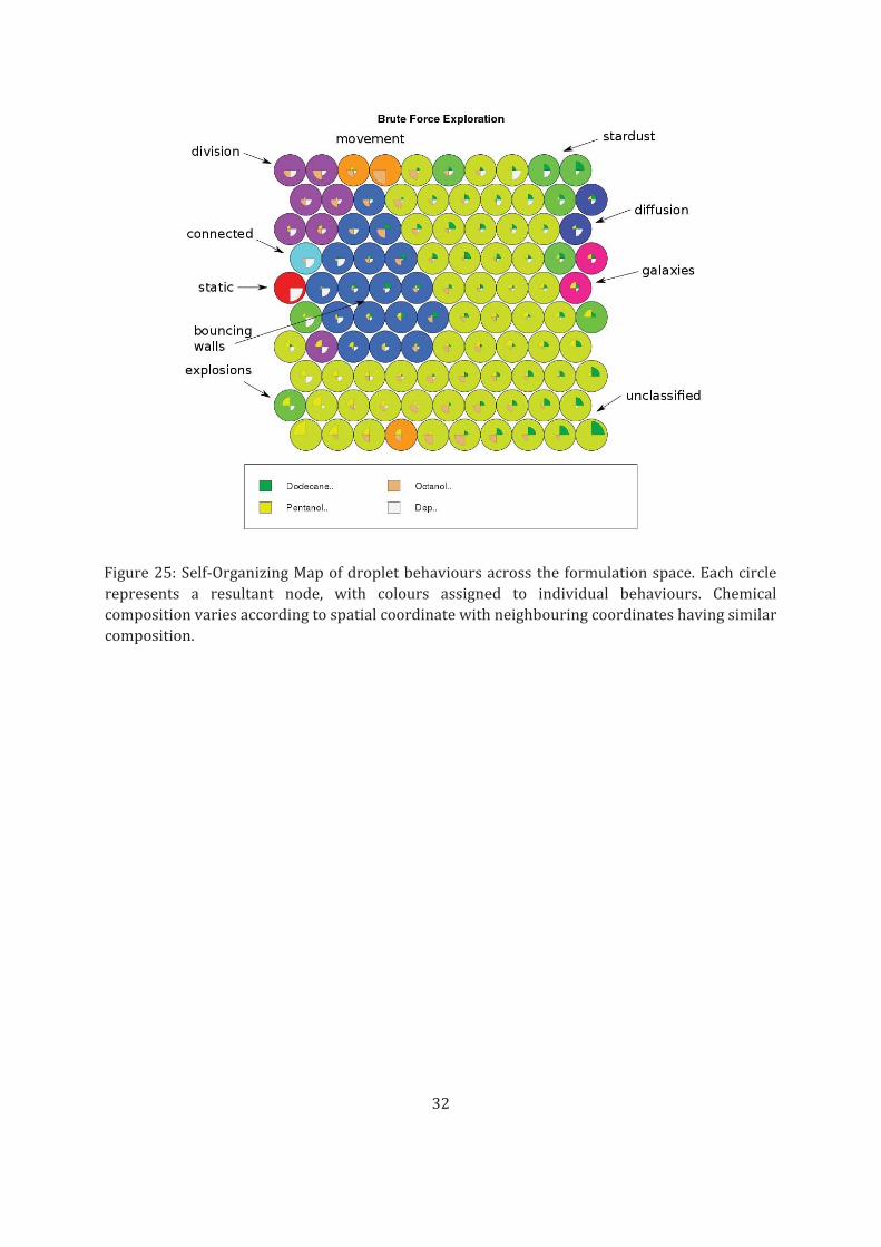
asintroductorytexts.Behavioursweremanuallyassigned,basedonvisualassessmentbyoneof
theresearchers.Eachcircleinfigure25representsa“node”:Thefundamentalunitofoutputfrom
theSOM.ChemicalcompositionvariesacrossboththeXandYaxesinaspatiallysignificant,but
visuallynon‐obviouspattern.Eachbehaviourisassignedanindividualcolouranditcanbeseen
thatbehaviourclustertogetherinspace,andthereforeincomposition.Eachclusterofbehaviours
thereforerepresentsaphenotypic“island”withinthecomposition/behaviourmapping.
Fitness F‐value p‐value
Division 407.8 <10−15Motility 259.1 <10−15Vibration 297 <10−15
Table6:ANOVAanalysisofallgenerations;theentiredistributionforeachgenerationwastested
asafunctionofgeneration,expressedasacategoricalvariable.Allfitnesslandscapesshowhighly
significantdifferencesinvariationbetweengenerations.
Fitness τ‐value Z‐value p‐value
Division 0.283 18.89 <10−15Motility 0.210 14.33 <10−15Vibration 0.256 17.50 <10−15
Table 7: Kendall rank‐correlation test of non‐linear dependence of fitness on generation,
expressed as a continuous variable. All fitness landscapes show a highly significant, positive
correlationbetweenthetwovariables.
32
Figure25:Self‐OrganizingMapofdropletbehavioursacrosstheformulationspace.Eachcircle
represents a resultant node, with colours assigned to individual behaviours. Chemical
compositionvariesaccordingtospatialcoordinatewithneighbouringcoordinateshavingsimilar
composition.

33
S.6 PrintedParts
S.6.1 Mainframe
S.6.1.1 3DPP1,trussbase
3DPP1Trussbaseforsolidcornerconnectionontherobotframe
S.6.1.2 3DPP2,trussfoot
3DPP2Trussbaseandintegratedfootforbottomhalf

34
S.6.2 X‐Yaxis
S.6.2.1 3DPP3,trussrod
3DPP3Trussbaseandintegratedrodholderforroundedsteelbar
S.6.2.2 3DPP4,trussmotor
3DPP4Trussbaseandintegratedmotorholderforpulleydrivers

35
S.6.2.3 3DPP5,Yidler
3DPP5XaxisrailrunnerwithattachmentsocketsforY‐axisrods
S.6.2.4 3DPP6,Yidlerwithmotor
3DPP6XaxisrailrunnerwithattachmentsocketsforY‐axisrodsandattachmentpointforYmotor

36
S.6.3 X‐Ycarriage
S.6.3.1 3DPP7,carriagemaincomponent
3DPP7Maincarriagecomponent,usedasattachmentpointforothercarriageapparatus
S.6.3.2 3DPP8,camerabackgroundpanel
3DPP8Holderforwhitepaneltoprovideuniformbackgroundthecamera.

37
S.6.3.3 3DPP9,panelsupport
3DPP9Supportingcomponenttosteadythebackgroundpanel.
S.6.3.4 3DPP10,panelgrip
3DPP10Supportingcomponenttosteadythebackgroundpanel.

38
S.6.4 Fluidhandling
S.6.4.1 3DPP11,tubeholder
3DPP11 Component for holding tubes incoming from the fluid platform, attaches to3DPP7.
S.6.4.2 3DPP12,sryingeholder
3DPP12Maincomponentforholdingsyringes,attachesto3DPP7.

39
S.6.4.3 3DPP13,syringeholdercap
3DPP13auxiliarycomponentforholdingsyringes,attachesto3DPP11.
S.6.4.4 3DPP14,plungercasing
3DPP14componentforholdingandactuatingthesyringeplungers.

40
S.6.4.5 3DPP15,syringetip
3DPP15componentforactuatingthesyringetipsupanddown.
S.6.4.6 3DPP16,crankshaft
3DPP16crankshaftforsyringeactuation,toattachtoinjectionmouldedmotorarm.

41
References
[1] Jones,R.,Haufe,P.,Sells,E.,Iravani,P.,Olliver,V.,Palmer,C.,andBowyer,A.,:RepRap‐TheReplicating Rapid Prototyper, Robotica (2011) volume 29, pp. 177–191. CambridgeUniversityPress.
[2] http://www.arduino.cc/
[3] Multipleauthors(1982).NumericalControlofMachinesISO69831:1982
[4] Yanev,K.etal(2011)https://github.com/kliment/Printrun
[5] G.vanRossumandF.L.Drake(eds),PythonReferenceManual,PythonLabs,Virginia,USA,2001.Availableathttp://www.python. org
[6] Liechti,C.(2001)http://pyserial.sourceforge.net/
[7] Yanev,K.etal(2010)https://github.com/kliment/Sprinter
[8] http://playground.arduino.cc/ComponentLib/Servo
[9] Kalman,R.E.(1960).ANewApproachtoLinearFilteringandPredictionProblems.JournalofBasicEngineering82(1):35–45.
[10] Pitt,M.K.;Shephard,N.(1999).FilteringViaSimulation:AuxiliaryParticleFilters.JournaloftheAmericanStatisticalAssociation94(446):590–591.
[11] Bradski,G.(2000)Dr.Dobb’sJournalofSoftwareTools.
[12] Jones, E., Oliphant, T., Peterson, P. et al (2001) SciPy: Open source scientific tools forPython.http://www.scipy.org/
[13] Duda,R.O.andP.E.Hart,(1972)UseoftheHoughTransformationtoDetectLinesandCurvesinPictures,Comm.ACM,Vol.15,pp.11–15
[14] Canny,J.,(1986)AComputationalApproachToEdgeDetection,IEEETrans.PatternAnalysisandMachineIntelligence,8(6):679–698
[15] Najman,L.andSchmitt,M.(1996)Geodesicsaliencyofwatershedcontoursandhierarchicalsegmentation.IEEETransactionsonPatternAnalysisandMachineIntelligence,Vol.18,Num.12,pages1163–1173.
[16] Reynolds, D.A.; Rose, R.C. (1995) Robust text‐independent speaker identification usingGaussianmixturespeakermodelsIEEETransactionsonSpeechandAudioProcessing3(1):72–83.
[17] Haynes,W.M.(2013).CRCHandbookofChemistryandPhysics,94thEdition.CRCPress,94thedition,
[18] Budavari,S.,Smith,A.,Heckelman,P.,Kinneary,J.andO’Neill,M.(1996)TheMerckIndex.Merck.

42
[19] Thomsen,M.,Carlsen,L.andHvidt,S.(2001)SolubilitiesandSurfaceActivitiesofPhthalatesInvestigated by Surface Tension Measurements. Experimental Toxicology and Chemistry,20(1):127–132.
[20] http://www.dynesonline.com/visc_table.html
[21] Jasper, J. J., and Kring, E. V. (1955) The Isobaric Surface Tensions and ThermodynamicPropertiesoftheSurfacesofaSeriesofn‐Alkanes,C5toC18,1‐Alkenes,C6toC16,andofn‐Decylcyclopentane, nDecylcyclohexane and n‐Dcylbenzene. Journal of Physical Chemistry,2142(3):3–5,1955.
[22] Rostamkolahi,A.M.,Rostami,A.A.,Koohyar,F.,andKiani,F.(2013)Thermodynamicprop+vinylacetate,diethylphthalate+vinylacetateorbromocyclohexane,anddibutylphthalate+vinylacetateor1,2‐dichlorobenzeneat298.15–308.15K.ChemicalPapers,67(11):1433–1441
[23] http://sigmaaldrich.com
[24] Tikhonov,A.N.(1963).Solutionof incorrectly formulatedproblemsandtheregularizationmethod.DokladyAkademiiNaukSSSR151:501–504..TranslatedinSovietMathematics4:1035–1038.
[25] Kohonen, T. (1982) Self‐Organized Formation of Topologically Correct Feature MapsBiologicalCybernetics43(1):59–69.
[26] Haykin,S.(1999).9.Self‐organizingmaps.Neuralnetworks‐Acomprehensivefoundation(2nded.).Prentice‐Hall.
[27] Jain, K. and Krug, J. (2007)Deterministicand StochasticRegimes ofAsexualEvolution onRuggedFitnessLandscapes.Genetics175:1275–1288
[28] Holm,S.(1979).Asimplesequentiallyrejectivemultipletestprocedure.ScandinavianJournalofStatistics6(2):65–70.
[29] Kendall,M.(1938).ANewMeasureofRankCorrelation.Biometrika30(1–2):81–89.
[30] Toyota,T.,Maru,N.,Hanczyc,M.M.,Ikegami,T.andSugawara,T.(2009)Self‐propelledoildropletsconsuming“fuel”surfactant.J.Am.Chem.Soc.131,5012–3.
[31] Hadorn,M. et al. (2012)Specificand reversibleDNA‐directed self‐assemblyofoil‐in‐wateremulsiondroplets.Proc.Natl.Acad.Sci.U.S.A.109,20320–5.