Embed Size (px)
Citation preview
University of Babylon, College of Engineering , Engineering Materials, Maithem H-Rasheed
Hardness testing
Hardness has already been defined as the resistance of a material
to indentation or abrasion by another hard body ( good hardness
generally means that the material is resistant to scratching and
wear) . It is by indentation that most hardness tests are
performed. A hard indenter is pressed into the specimen by a
standard load, and the magnitude of the indentation (either area
or depth) is taken as a measure of hardness.
Hardness tests are commonly used for assessing material
properties because they are quick and convenient. However, a
variety of testing methods is appropriate due to differences in
hardness among different materials. The most well known
hardness tests are Brinell and Rockwell.
Hardness is a measure of the material’s resistance to
localized plastic deformation (e.g. dent or scratch)
A qualitative Moh’s scale, determined by the ability of a
material to scratch another material: from 1 (softest = talc) to
10 (hardest = diamond).
Diamond 10
Corundum 9
Topaz 8
Quartz 7
Orthoclase (Feldspar) 6
Apatite 5
Fluorite 4
Calcite 3
Gypsum 2
Talc 1
Different types of quantitative hardness test have been designed
(Rockwell, Brinell, Vickers, etc.).
University of Babylon, College of Engineering , Engineering Materials, Maithem H-Rasheed
Usually a small indenter (sphere, cone, or pyramid) is forced
into the surface of a material under conditions of controlled
magnitude and rate of loading. The depth or size of indentation
is measured.
The tests somewhat approximate, but popular because they are
easy and non-destructive (except for the small dent).
Some limitation for hardness test as follows :-
Type of material
Specimen thickness
Test location
Scale limitations
1. The Brinell hardness test
J.A. Brinell introduced the first standardized indentation-
hardness test in 1900.
The Brinell hardness test consists in indenting the metal surface
with a 10-mm diameter steel or tungsten carbide ball at a load
range of 500-3000 kg, depending of hardness of particular
materials.
The load is applied for a standard time ( between 10 - 30 s), and
the diameter of the indentation is measured. Giving an average
value of two readings of the diameter of the indentation at right
angle.
• The Brinell hardness number (BHN or HB) is expressed as
2. the load P divided by surface area of the indentation
In this test, hardness is measured by pressing a hard steel ball
into the surface of the test piece, using a known load. It is
important to choose the combination of load and ball size
carefully so that the indentation is free from distortion and
suitable for measurement.
University of Babylon, College of Engineering , Engineering Materials, Maithem H-Rasheed
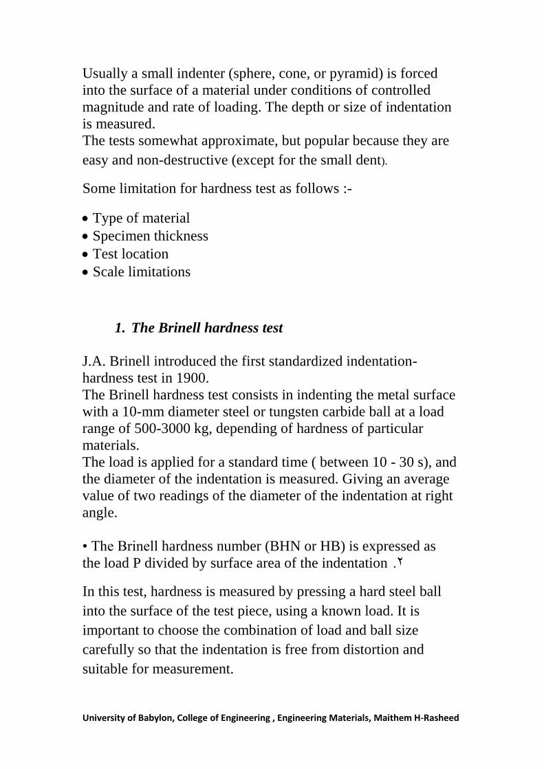
The relationship of the Brinell hardness [HB] which is between
load P (kg), the diameter D (mm) of the hardened ball indenter
and the diameter d (mm) of the indentation on the surface is
given by the expression:
√
Where:
P: applied load (kg)
D: diameter of ball (indenter) (mm)
d: diameter of indentation (mm)
The Brinell hardness number followed by the symbol HB
For different materials, the ratio ( p / D2 ) has been standardized
in order to obtain accurate and comparative results such as :
K = p / D2
Where K is. a constant; typical values of K are:
Ferrous metals K = 30
Copper and copper alloys K = 10
Aluminum and aluminum alloys K = 5
Lead, tin and white-bearing metals K = 1
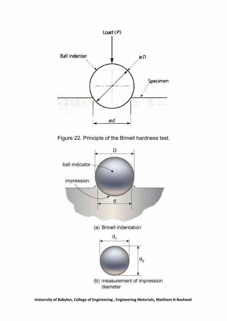
Figure 22 shows how the Brinell hardness value is determined.
The diameter of the indentation is measured in two directions at
right angles and the average taken. The diameter is measured
either by using a microscope scale, or by a projection screen
with micrometer adjustment.
University of Babylon, College of Engineering , Engineering Materials, Maithem H-Rasheed
Figure 22. Principle of the Brinell hardness test.
University of Babylon, College of Engineering , Engineering Materials, Maithem H-Rasheed
To ensure consistent results, the following precautions should be
observed.
1- The thickness of the specimen should be at least seven
times the depth of the indentation to allow unrestricted
plastic flow below the indenter.
2- The edge of the indentation should be at least three times
the diameter of the indentation from the edge of the test
piece.
3- The test is unsuitable for materials whose hardness
exceeds 500 HB, as the ball indenter tends to flatten.
There are a definite relationship between strength and hardness
so it is possible to measure the tensile strength from the
hardness test.
Advantage and disadvantages of Brinell hardness
test
• Different loads are used to cover a wide range of hardness of
commercial metals.
• Brinell hardness test is less influenced by surface scratches and
roughness than other hardness tests.
• The test has limitations on small specimens or in critically
stressed parts where indentation could be a possible site of
failure
2- The Vickers hardness test
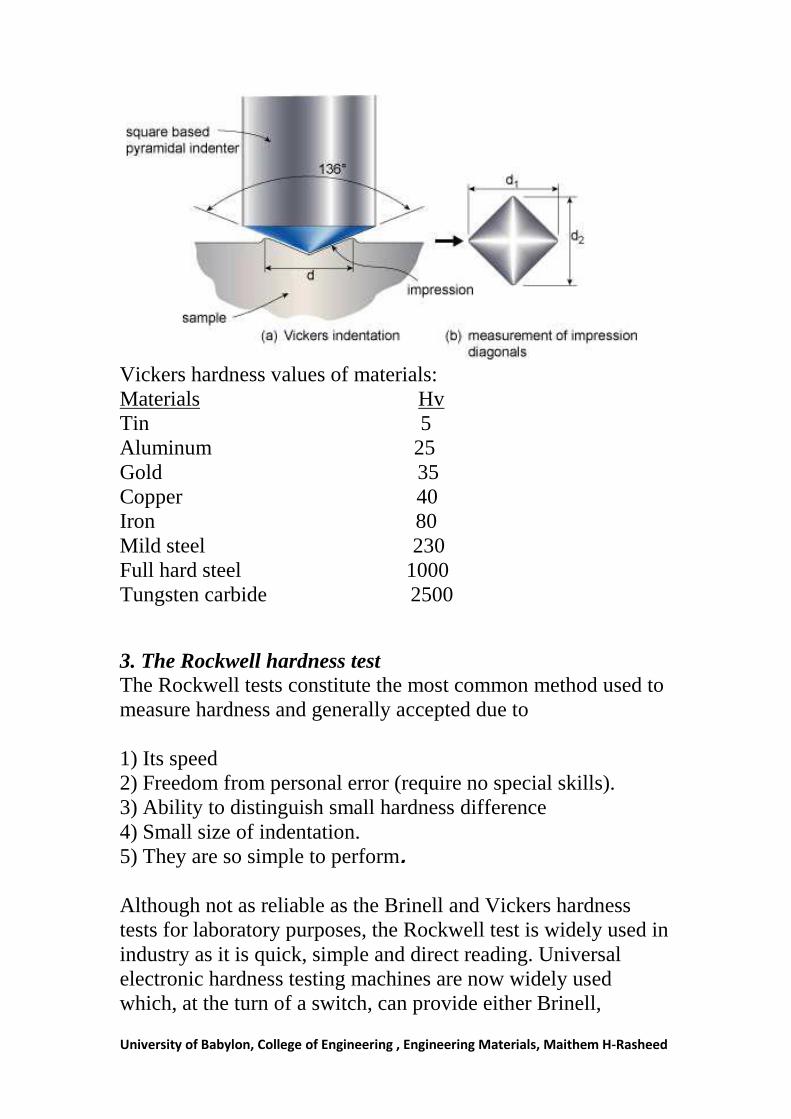
Vickers hardness test uses a square-base diamond pyramid as
the indenter with the included angle between opposite faces of
the pyramid of 136o.
The Vickers hardness number (VHN) is defined as the load
divided by the surface area of the indentation.
This test is preferable to the Brinell test where hard materials are
concerned, as it uses a diamond indenter. (Diamond is the
hardest material known - approximately 6000 HB.)
University of Babylon, College of Engineering , Engineering Materials, Maithem H-Rasheed
Standard loads are 5, 10, 20. 30, 50 and 1 00 kg. It is necessary
to state the load when specifying a Vickers hardness number.
For example, if the hardness number is found to be 200 when
using a 50 kg load, then the hardness number is written as
HV (50) = 200.
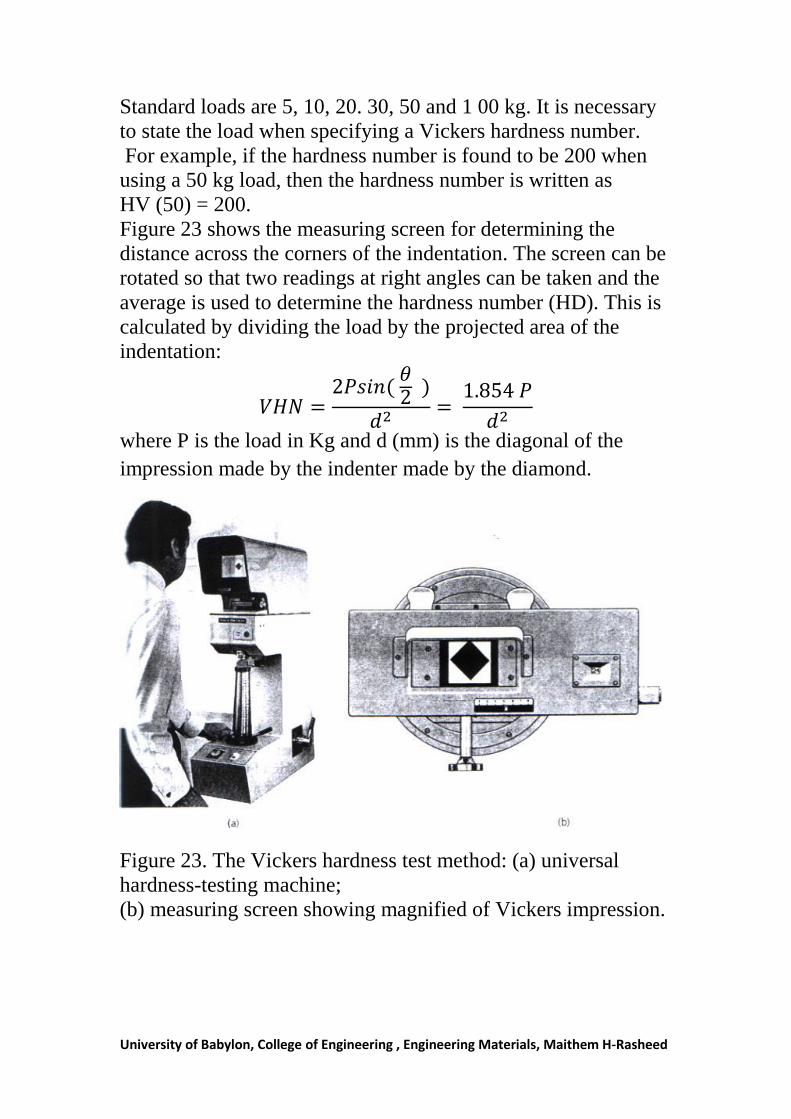
Figure 23 shows the measuring screen for determining the
distance across the corners of the indentation. The screen can be
rotated so that two readings at right angles can be taken and the
average is used to determine the hardness number (HD). This is
calculated by dividing the load by the projected area of the
indentation:
where P is the load in Kg and d (mm) is the diagonal of the
impression made by the indenter made by the diamond.
Figure 23. The Vickers hardness test method: (a) universal
hardness-testing machine;
(b) measuring screen showing magnified of Vickers impression.
University of Babylon, College of Engineering , Engineering Materials, Maithem H-Rasheed
Vickers hardness values of materials:
Materials Hv
Tin 5
Aluminum 25
Gold 35
Copper 40
Iron 80
Mild steel 230
Full hard steel 1000
Tungsten carbide 2500
3. The Rockwell hardness test
The Rockwell tests constitute the most common method used to
measure hardness and generally accepted due to
1) Its speed
2) Freedom from personal error (require no special skills).
3) Ability to distinguish small hardness difference
4) Small size of indentation.
5) They are so simple to perform. Although not as reliable as the Brinell and Vickers hardness
tests for laboratory purposes, the Rockwell test is widely used in
industry as it is quick, simple and direct reading. Universal
electronic hardness testing machines are now widely used
which, at the turn of a switch, can provide either Brinell,
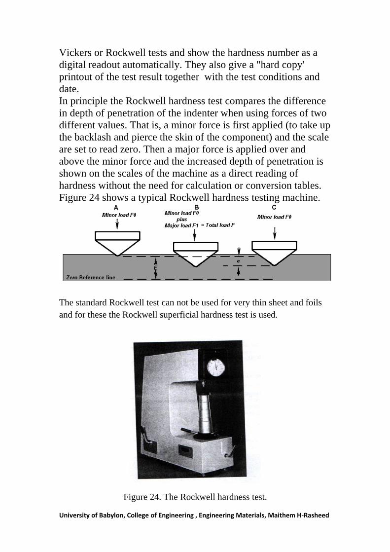
University of Babylon, College of Engineering , Engineering Materials, Maithem H-Rasheed
Vickers or Rockwell tests and show the hardness number as a
digital readout automatically. They also give a "hard copy'
printout of the test result together with the test conditions and
date.
In principle the Rockwell hardness test compares the difference
in depth of penetration of the indenter when using forces of two
different values. That is, a minor force is first applied (to take up
the backlash and pierce the skin of the component) and the scale
are set to read zero. Then a major force is applied over and
above the minor force and the increased depth of penetration is
shown on the scales of the machine as a direct reading of
hardness without the need for calculation or conversion tables.
Figure 24 shows a typical Rockwell hardness testing machine.
The standard Rockwell test can not be used for very thin sheet and foils
and for these the Rockwell superficial hardness test is used.
Figure 24. The Rockwell hardness test.
University of Babylon, College of Engineering , Engineering Materials, Maithem H-Rasheed
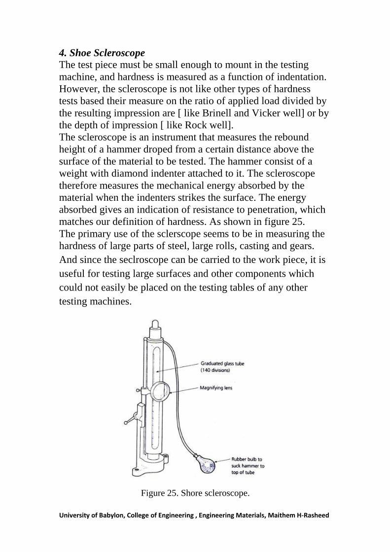
4. Shoe Scleroscope
The test piece must be small enough to mount in the testing
machine, and hardness is measured as a function of indentation.
However, the scleroscope is not like other types of hardness
tests based their measure on the ratio of applied load divided by
the resulting impression are [ like Brinell and Vicker well] or by
the depth of impression [ like Rock well].
The scleroscope is an instrument that measures the rebound
height of a hammer droped from a certain distance above the
surface of the material to be tested. The hammer consist of a
weight with diamond indenter attached to it. The scleroscope
therefore measures the mechanical energy absorbed by the
material when the indenters strikes the surface. The energy
absorbed gives an indication of resistance to penetration, which
matches our definition of hardness. As shown in figure 25.
The primary use of the sclerscope seems to be in measuring the
hardness of large parts of steel, large rolls, casting and gears.
And since the seclroscope can be carried to the work piece, it is
useful for testing large surfaces and other components which
could not easily be placed on the testing tables of any other
testing machines.
Figure 25. Shore scleroscope.
University of Babylon, College of Engineering , Engineering Materials, Maithem H-Rasheed
Creep test Even at constant stress, materials continue to deform for an
indefinite period of time. This time – dependent deformation is
called creep. At temperatures less than 40 percent of the
absolute melting point, the extent of creep is negligible, but at
temperatures higher than this it becomes increasingly important.
It is for this reason that the creep test is commonly thought of as
a high-temperature test.
The majority of creep testing is conducted in the tensile mode,
and the type of test-piece used is similar to the normal tensile
test-piece. Most creep testing is carried out under constant-load
conditions and utilizes dead weights acting through a simple
lever system. In the creep testing an extensometer readings are
noted at regular time interval s until the required a mount of data
has been obtained, or until the test-piece fractures, depending on
whether the object of the test is to determine the creep rate or to
determine the total creep strain.
One of the difficulties in creep testing is that a single test may
take
A very long time to complete (10000 hours is 417 days), and
there are serious difficulties in attempting to extrapolate from
the results of comparatively short-term tests to assess the
probable behavior of a material over a 10 or 20 year period of
service.
Modern creep-testing laboratories may contain several hundred
creep-testing machines in continuous use.
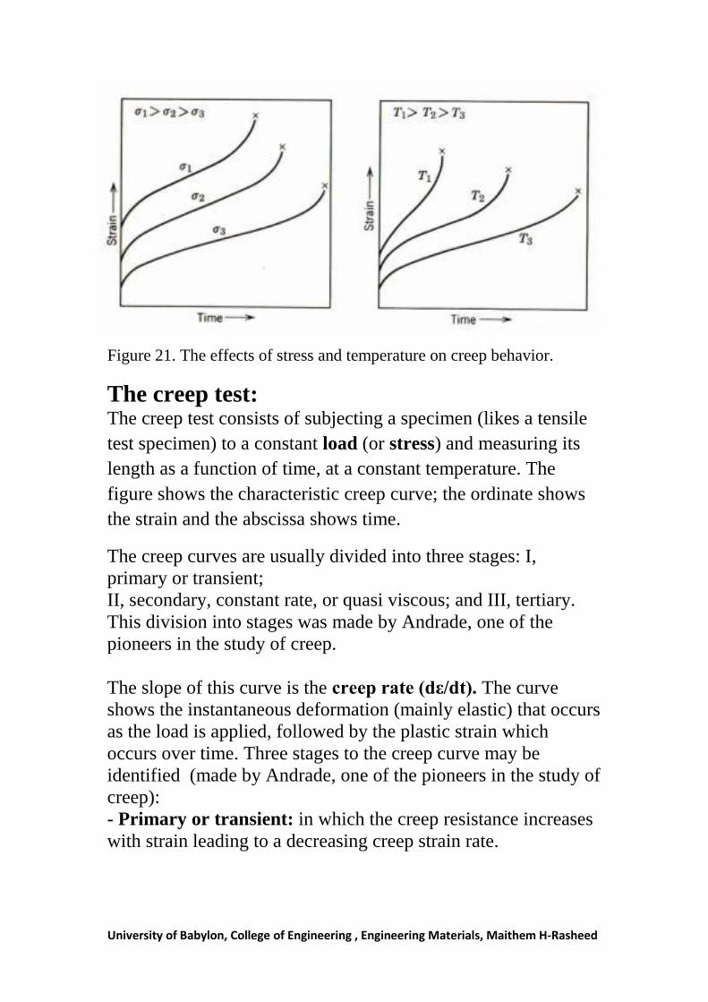
Also creep is sensitive to both the applied load and the testing
temperature, as shown in figure 21: increasing stress raises the
level of the creep curve, and increasing temperature, which
accelerates recovery processes, increase the creep rate.
University of Babylon, College of Engineering , Engineering Materials, Maithem H-Rasheed
Figure 21. The effects of stress and temperature on creep behavior.
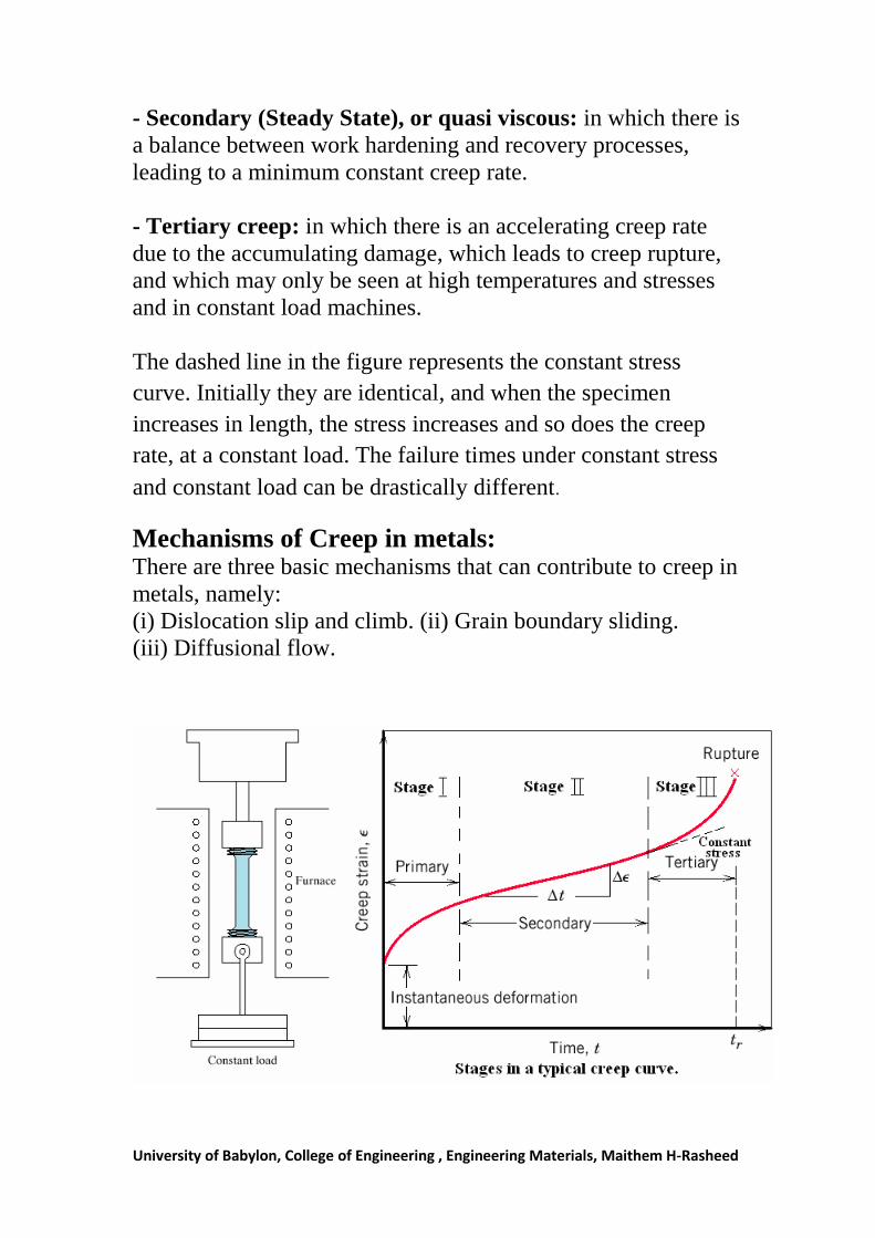
The creep test: The creep test consists of subjecting a specimen (likes a tensile
test specimen) to a constant load (or stress) and measuring its
length as a function of time, at a constant temperature. The
figure shows the characteristic creep curve; the ordinate shows
the strain and the abscissa shows time.
The creep curves are usually divided into three stages: I,
primary or transient;
II, secondary, constant rate, or quasi viscous; and III, tertiary.
This division into stages was made by Andrade, one of the
pioneers in the study of creep.
The slope of this curve is the creep rate (dε/dt). The curve
shows the instantaneous deformation (mainly elastic) that occurs
as the load is applied, followed by the plastic strain which
occurs over time. Three stages to the creep curve may be
identified (made by Andrade, one of the pioneers in the study of
creep):
- Primary or transient: in which the creep resistance increases
with strain leading to a decreasing creep strain rate.
University of Babylon, College of Engineering , Engineering Materials, Maithem H-Rasheed
- Secondary (Steady State), or quasi viscous: in which there is
a balance between work hardening and recovery processes,
leading to a minimum constant creep rate.
- Tertiary creep: in which there is an accelerating creep rate
due to the accumulating damage, which leads to creep rupture,
and which may only be seen at high temperatures and stresses
and in constant load machines.
The dashed line in the figure represents the constant stress
curve. Initially they are identical, and when the specimen
increases in length, the stress increases and so does the creep
rate, at a constant load. The failure times under constant stress
and constant load can be drastically different.
Mechanisms of Creep in metals: There are three basic mechanisms that can contribute to creep in
metals, namely:
(i) Dislocation slip and climb. (ii) Grain boundary sliding.
(iii) Diffusional flow.