Embed Size (px)
Citation preview
INDIAN INSTITUTE OF ASTROPHYSICS
Hanle Echelle SpectrographObservers guide to the instrument
Version history
1st draft version - 05-May-16 - Figures and caption with minimum text
The document aims to provide quick overview of the instrument and its subsystem

Hanle Echelle Spectrograph
Overview: Hanle echelle spectrograph is a bench mounted, dual fibre-fed spectrograph. It has spectral resolution of R = 30,000 and 60,000 and uses an R2 grating and a 4Kx4K E2V CCD to cover the wavelength region 350-1000nm. This is one of the 2nd generation instrument spectrograph for the 2m HCT telescope. The instrument covers the entire optical wavelength in a single instrument setup, without any gap in the wavelength coverage.
The spectrograph is built by Callaghan innovation, New Zealand and the instrument control interface was developed by Indian Institute of Astrophysics. The project is funded by Department of Science and Technology (DST), India. Instrument specification:
Description
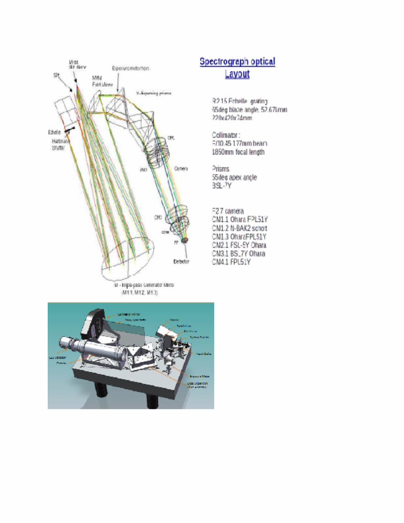
Optical layout White pupil with triple-pass collimator
Spectral Resolution R=30000, 60000 (with image slicer)
Wavelength Coverage 350-1000nm
Observing modes Dual/single fiber mode (stat-sky, star-calib,calib-calib modes)
Stability 200m/s
RV precision 20m/s (simultaneous ThAr)
Efficiency 22 % peak efficiency
Entrance aperture 2.7arcsec (250micron diameter pinhole) Two pinholes separated by 1.25mm (~ 13arcsec)
Telescope F-ratio f/9.2
Fiber feed f/3.6
Slit width 0.14mm (high-res), 0.34mm (low res)
Spectrograph Beam size 177mm (f/10)
!
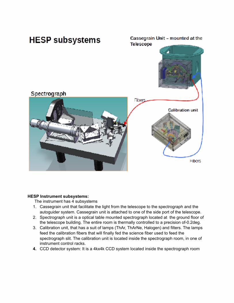
HESP Instrument subsystems: The instrument has 4 subsystems
1. Cassegrain unit that facilitate the light from the telescope to the spectrograph and the autoguider system. Cassegrain unit is attached to one of the side port of the telescope.
2. Spectrograph unit is a optical table mounted spectrograph located at the ground floor of the telescope building. The entire room is thermally controlled to a precision of-0.2deg.
3. Calibration unit, that has a suit of lamps (ThAr, ThArNe, Halogen) and filters. The lamps feed the calibration fibers that will finally fed the science fiber used to feed the spectrograph slit. The calibration unit is located inside the spectrograph room, in one of instrument control racks.
4. CCD detector system: It is a 4kx4k CCD system located inside the spectrograph room
!

Cassegrain unit: Light from HCT (2m telescope) at f/9.2 is directed by a 45° fold mirror through a side port of the instrument mounting cube. A 45° fold mirror redirects the light parallel to the instrument mounting plane. The cassegrain unit includes the ADC corrector, Auto guiding unit along with fiber input unit and an alignment cube.
!
Light from the Telescope M3 into the HESP sideport where cassegrain
Cassegrain unit optical layout
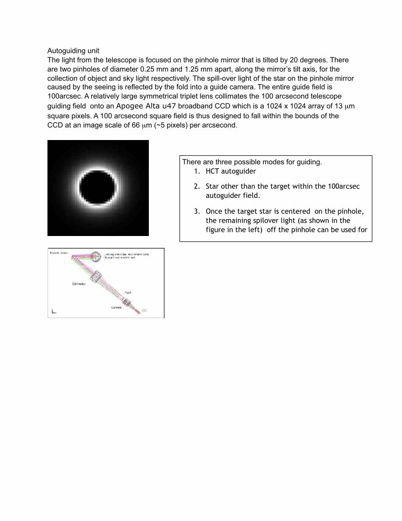
Autoguiding unit The light from the telescope is focused on the pinhole mirror that is tilted by 20 degrees. There are two pinholes of diameter 0.25 mm and 1.25 mm apart, along the mirror’s tilt axis, for the collection of object and sky light respectively. The spill-over light of the star on the pinhole mirror caused by the seeing is reflected by the fold into a guide camera. The entire guide field is 100arcsec. A relatively large symmetrical triplet lens collimates the 100 arcsecond telescope guiding field onto an Apogee Alta u47 broadband CCD which is a 1024 x 1024 array of 13 µm square pixels. A 100 arcsecond square field is thus designed to fall within the bounds of the CCD at an image scale of 66 µm (~5 pixels) per arcsecond.
!
!
There are three possible modes for guiding. 1. HCT autoguider
2. Star other than the target within the 100arcsec autoguider field.
3. Once the target star is centered on the pinhole, the remaining spilover light (as shown in the figure in the left) off the pinhole can be used for
!
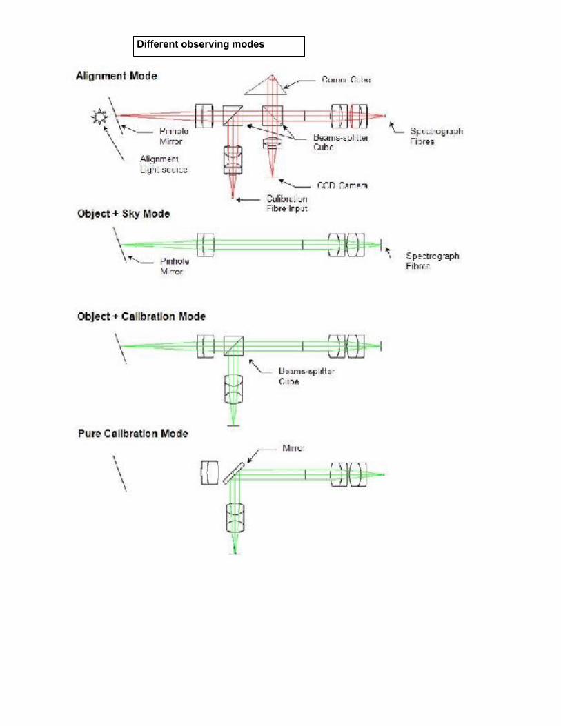
Different observing modes
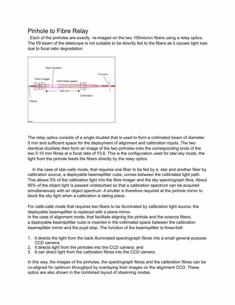
Pinhole to Fibre Relay . Each of the pinholes are exactly re-imaged on the two 100micron fibers using a relay optics. The f/9 beam of the telescope is not suitable to be directly fed to the fibers as it causes light loss due to focal ratio degradation.
!
The relay optics consists of a single doublet that is used to form a collimated beam of diameter 5 mm and sufficient space for the deployment of alignment and calibration inputs. The two identical doublets then form an image of the two pinholes onto the corresponding ends of the two 0.10 mm fibres at a focal ratio of f/3.6. This is the configuration used for star-sky mode, the light from the pinhole feeds the fibers directly by the relay optics.
In the case of star-calib mode, that requires one fiber to be fed by a star and another fiber by calibration source, a deployable beamsplitter cube, comes between the collimated light path. This allows 5% of the calibration light into the fibre imager and the sky spectrograph fibre. About 95% of the object light is passed undisturbed so that a calibration spectrum can be acquired simultaneously with an object spectrum. A shutter is therefore required at the pinhole mirror to block the sky light when a calibration is taking place.
For calib-calib mode that requires two fibers to be illuminated by calibration light source, the deployable beamsplitter is replaced with a plane mirror. In the case of alignment mode, that facilitate aligning the pinhole and the science fibers, a deployable beamsplitter cube is inserted in the collimated space between the calibration beamsplitter mirror and the pupil stop. The function of the beamsplitter is three-fold:
1. It directs the light from the back illuminated spectrograph fibres into a small general purpose CCD camera;
2. It directs light from the pinholes into the CCD camera; and 3. It can direct light from the calibration fibres into the CCD camera.
In this way, the images of the pinholes, the spectrograph fibres and the calibration fibres can be co-aligned for optimum throughput by overlaying their images on the alignment CCD. These optics are also shown in the combined layout of observing modes.
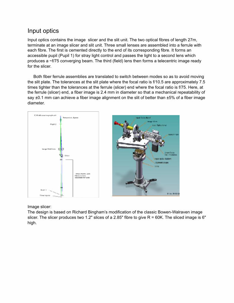
Input optics Input optics contains the image slicer and the slit unit. The two optical fibres of length 27m, terminate at an image slicer and slit unit. Three small lenses are assembled into a ferrule with each fibre. The first is cemented directly to the end of its corresponding fibre. It forms an accessible pupil (Pupil 1) for stray light control and passes the light to a second lens which produces a ~f/75 converging beam. The third (field) lens then forms a telecentric image ready for the slicer.
Both fiber ferrule assemblies are translated to switch between modes so as to avoid moving the slit plate. The tolerances at the slit plate where the focal ratio is f/10.5 are approximately 7.5 times tighter than the tolerances at the ferrule (slicer) end where the focal ratio is f/75. Here, at the ferrule (slicer) end, a fiber image is 2.4 mm in diameter so that a mechanical repeatability of say ±0.1 mm can achieve a fiber image alignment on the slit of better than ±5% of a fiber image diameter.
!
Image slicer: The design is based on Richard Bingham’s modification of the classic Bowen-Walraven image slicer. The slicer produces two 1.2" slices of a 2.85" fibre to give R = 60K. The sliced image is 6" high.
! !
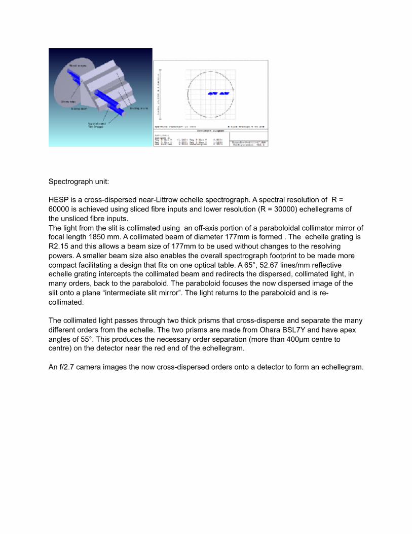
Spectrograph unit:
HESP is a cross-dispersed near-Littrow echelle spectrograph. A spectral resolution of R = 60000 is achieved using sliced fibre inputs and lower resolution (R = 30000) echellegrams of the unsliced fibre inputs. The light from the slit is collimated using an off-axis portion of a paraboloidal collimator mirror of focal length 1850 mm. A collimated beam of diameter 177mm is formed . The echelle grating is R2.15 and this allows a beam size of 177mm to be used without changes to the resolving powers. A smaller beam size also enables the overall spectrograph footprint to be made more compact facilitating a design that fits on one optical table. A 65°, 52.67 lines/mm reflective echelle grating intercepts the collimated beam and redirects the dispersed, collimated light, in many orders, back to the paraboloid. The paraboloid focuses the now dispersed image of the slit onto a plane “intermediate slit mirror”. The light returns to the paraboloid and is re-collimated.
The collimated light passes through two thick prisms that cross-disperse and separate the many different orders from the echelle. The two prisms are made from Ohara BSL7Y and have apex angles of 55°. This produces the necessary order separation (more than 400µm centre to centre) on the detector near the red end of the echellegram.
An f/2.7 camera images the now cross-dispersed orders onto a detector to form an echellegram.
!
!
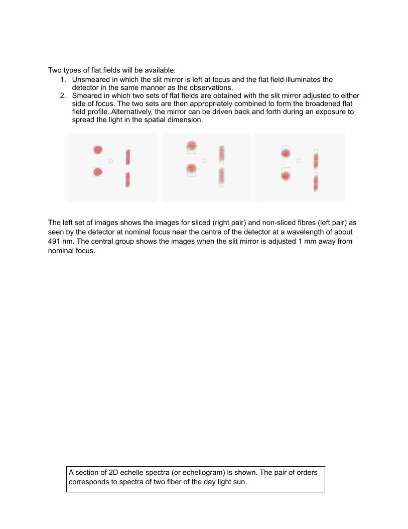
Two types of flat fields will be available: 1. Unsmeared in which the slit mirror is left at focus and the flat field illuminates the
detector in the same manner as the observations. 2. Smeared in which two sets of flat fields are obtained with the slit mirror adjusted to either
side of focus. The two sets are then appropriately combined to form the broadened flat field profile. Alternatively, the mirror can be driven back and forth during an exposure to spread the light in the spatial dimension.
! The left set of images shows the images for sliced (right pair) and non-sliced fibres (left pair) as seen by the detector at nominal focus near the centre of the detector at a wavelength of about 491 nm. The central group shows the images when the slit mirror is adjusted 1 mm away from nominal focus.
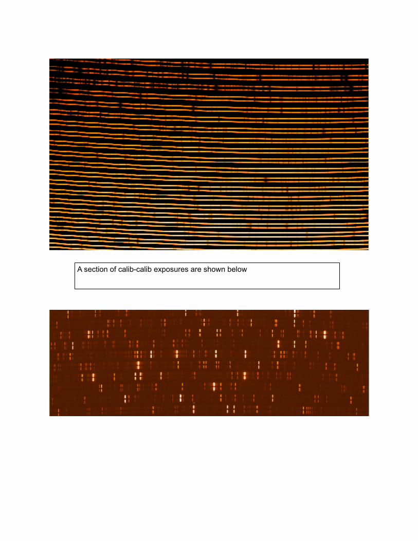
A section of 2D echelle spectra (or echellogram) is shown. The pair of orders corresponds to spectra of two fiber of the day light sun.
!
!
A section of calib-calib exposures are shown below
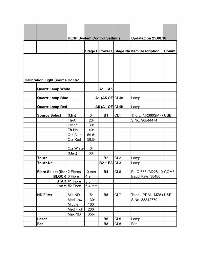
HESP System Control Settings Updated on 25.08.16
Stage PositionPower Switch SelectStage NameItem Description Comm. Port
Calibration Light Source Control
Quartz Lamp White A1 + A5
Quartz Lamp Blue A1 (A5 OFF)CL4a Lamp
Quartz Lamp Red A5 (A1 OFF)CL4b Lamp
Source Select (Min) 0◦ B1 CL1 ThorL, NR360SM (74)USBTh-Ar 20◦ S.No. 90844474Laser 30◦Th-Ne 40◦Qtz Blue 59.5◦Qtz Red 59.5◦
Qtz White 0◦(Max) 60◦
Th-Ar B2 CL2 LampTh-Ar-Ne B2 + B3 CL3 Lamp
Fibre Select (Star + Sky)2 Fibres 0 mm B4 CL6 PI, C-663 (M228.10S)COM3BLOCK 0 Fibre 4.9 mm Baud Rate: 38400
STAR #1 Fibre 3.3 mmSKY #2 Fibre 6.4 mm
ND Filter Min ND 5◦ B5 CL7 ThorL, PRM1-MZ8 (70)USBMed Low 130◦ S.No. 83842770Middle 160◦Med High 200◦Max ND 355◦
Laser B6 CL5 LampFan B8 CL8 Fan

Spectrograph Control after Replacing New Industrial PC and DC PS During Aug 2016 MaintenanceSEPC A2 Control Computer
Resolution Low 9.35 mm A3 S1 Newport SMC100 Com 1
High 16.57 mm
PMT A4 S5: 5V SMPS
System Shutter A4 S2: 12V SMPS
Back Light Left 0 mm A6 S3: 24 V SMPSAPT LTS 300 USB
Backlight 47.5 mmRight 95 mm
Park 230 mm
Focus @ 20.6 Deg C15.8 mm A3 S4 Newport SMC100 Com 2PMT Shutter A7 S8 Uniblitz Com 5
CCD Workstation PC A8Temp Controller B7 Com 6
Cassegrain Control
Temp Control A2 Temperature MonitorCom 4A & G Camera A3 C6 Apogee USB
Mode Select (mirror)Cal-Cal 0 mm A4 C4- Aplab 15V -O/P:1ThorL, APT43 (25) USB
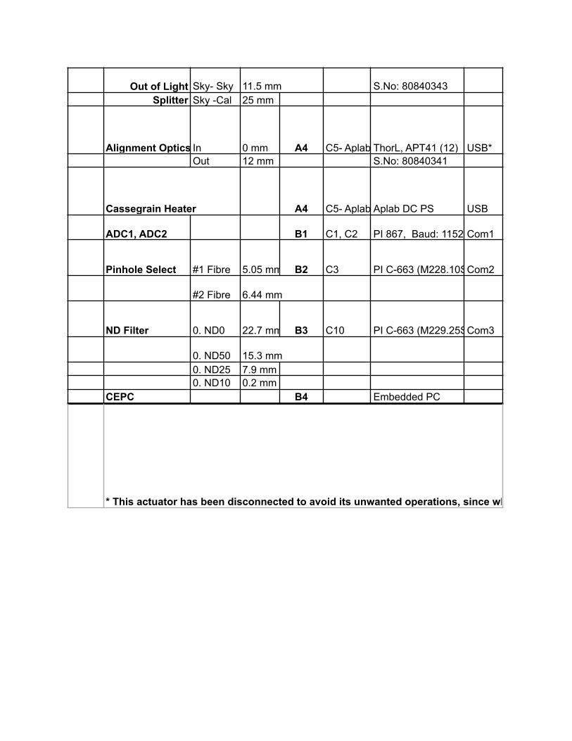
Out of Light Sky- Sky 11.5 mm S.No: 80840343Splitter Sky -Cal 25 mm
Alignment Optics In 0 mm A4 C5- Aplab 15V -O/P:1ThorL, APT41 (12) USB*Out 12 mm S.No: 80840341
Cassegrain Heater A4 C5- Aplab 0 to 24V -O/P:2Aplab DC PS USB
ADC1, ADC2 B1 C1, C2 PI 867, Baud: 115200Com1
Pinhole Select #1 Fibre 5.05 mm B2 C3 PI C-663 (M228.10S), Baud Rate: 38400Com2
#2 Fibre 6.44 mm
ND Filter 0. ND0 22.7 mm B3 C10 PI C-663 (M229.25S), Baud Rate: 38400Com3
0. ND50 15.3 mm0. ND25 7.9 mm0. ND10 0.2 mm
CEPC B4 Embedded PC
* This actuator has been disconnected to avoid its unwanted operations, since while moving it is making noise.

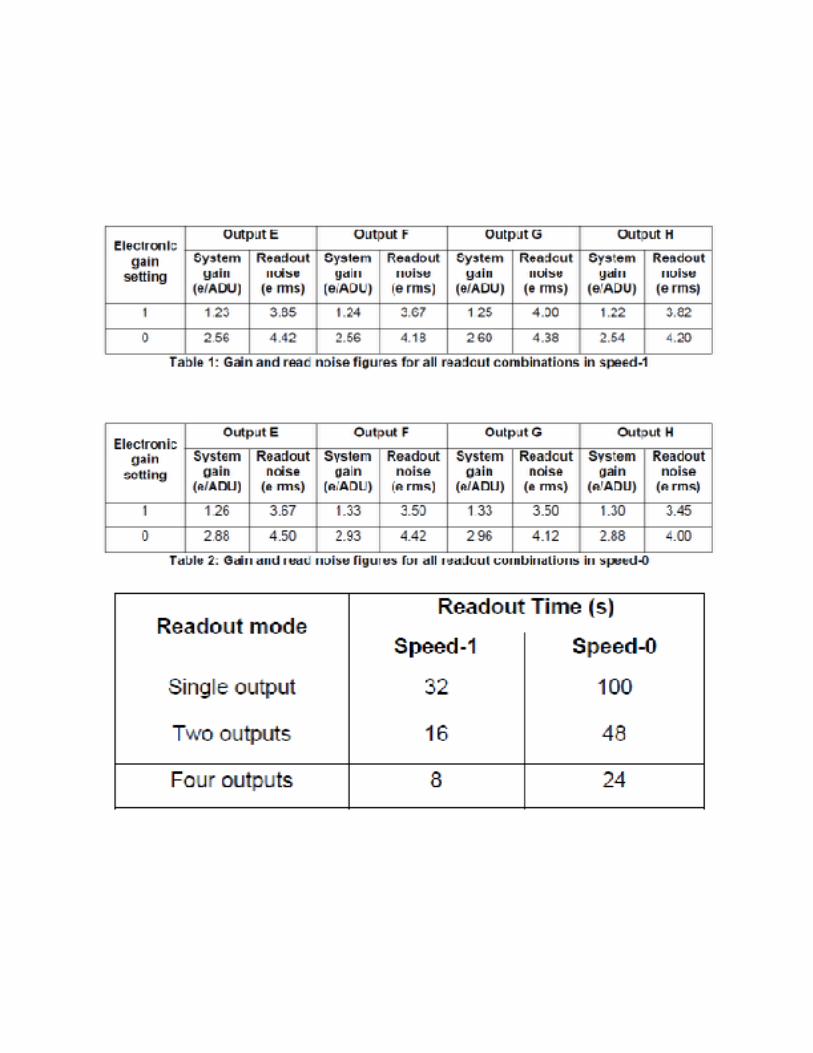
HESP CCD specifications
!
!