Embed Size (px)
Citation preview

Hands On: Introduction to Safety Workshop Presented by…Robert Jones
Manufacturing in America │ March 14-15, 2018
Unrestricted © Siemens 2018 All rights reserved. Community. Collaboration. Innovation.
Before we start… A Penny for Your Thoughts
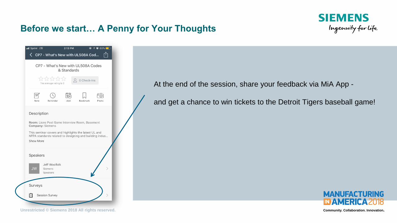
At the end of the session, share your feedback via MiA App -
and get a chance to win tickets to the Detroit Tigers baseball game!

Unrestricted © Siemens 2018 All rights reserved. Community. Collaboration. Innovation.
Machine Safety
Safety Process Chain
Cutting disc > Cutting off
Transport rollers > Crushing and shearing
Clamping plates > Crushing
Chips > Cutting, penetrating
Risk assessment Risk reduction Proof
The necessary steps towards a safe machine can be illustrated with a process chain.

Unrestricted © Siemens 2018 All rights reserved. Community. Collaboration. Innovation.
Machine Safety
Are Risk Assessments Required?
Risk assessment Risk reduction Proof
DIRECTIVE 2006/42/EC
(Machinery Directive)
European Union : USA:
NFPA 79 ANSI B11.19 ANSI / RIA 15.06 ANSI ASSE Z244.1
YES! All new & revised machine safety standards state that a “Risk assessment” MUST be
performed

Unrestricted © Siemens 2018 All rights reserved. Community. Collaboration. Innovation.
Machine Safety
Methods of Risk Mitigation
Safety Implementations
• Physical safety measures
Barriers (e.g. guards, enclosures), protective clothing and
equipment, floor markings
• Safety awareness
General safety education courses, proper equipment training,
regular internal safety evaluation
• Safety controls
Input devices (e.g. sensors, pilot devices), safety evaluation
devices, Output devices (e.g. contactors, motor starter protection)
Unrestricted © Siemens 2018 All rights reserved. Community. Collaboration. Innovation.
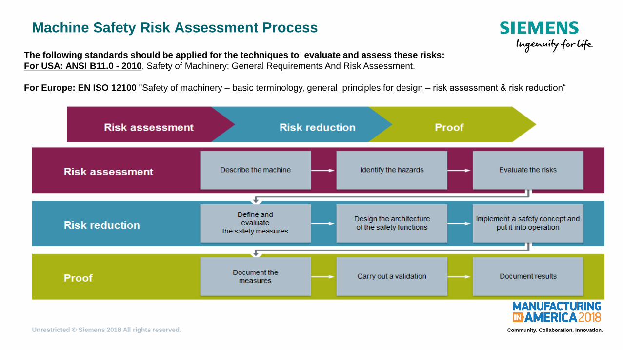
Machine Safety Risk Assessment Process
The following standards should be applied for the techniques to evaluate and assess these risks:
For USA: ANSI B11.0 - 2010, Safety of Machinery; General Requirements And Risk Assessment.
For Europe: EN ISO 12100 "Safety of machinery – basic terminology, general principles for design – risk assessment & risk reduction“

Unrestricted © Siemens 2018 All rights reserved. Community. Collaboration. Innovation.
Machine Safety
Quantifying Risk
Risk assessment Risk reduction Proof Risk assessment

Unrestricted © Siemens 2018 All rights reserved. Community. Collaboration. Innovation.
Machine Safety
Determination of required SIL
Risk assessment Risk reduction Proof Risk assessment

Unrestricted © Siemens 2018 All rights reserved. Community. Collaboration. Innovation.
Machine Safety
Determination of required PL
Risk assessment Risk assessment Risk assessment Risk reduction Proof Risk assessment

Unrestricted © Siemens 2018 All rights reserved. Community. Collaboration. Innovation.
Machine Safety
Typical Safety Circuit – example SIL 3 / PL e wiring
24V or 115VAC Power Supply
0V
Sensors
Initiate machine shut
down
Positive Opening
Guarantees that all
NC contacts are in
the open position
when actuated
Redundancy
ensures safety
functionality even if a
failure disables one
channel
Evaluation
Fault detection and
evaluation; opens the
circuit in case of a
failure.
Positive Driven (Mirror)
Guarantees that NC contacts are
not to be closed at the same time
as the main contact
Feedback Loop
Monitors the correct
operation of the
contactor coils
Reset
Reactivates the
safety circuit
The Complete Safety Solution
Safety Controller
OR

Unrestricted © Siemens 2018 All rights reserved. Community. Collaboration. Innovation.
Machine Safety
Understanding Safety Levels - PL a
Standard Switch and Contactor PL a allows
• NO contacts for
• Enabling
• Two-hand control
• Restart
L1 L2 L3
The Complete Safety Solution

Unrestricted © Siemens 2018 All rights reserved. Community. Collaboration. Innovation.
Machine Safety
Understanding Safety Levels - PL b
24 VDC
0 VDC
Op
en
Clo
se
d
PL b requires
• Sensors with positive
opening contacts
L1 L2 L3
The Complete Safety Solution

Unrestricted © Siemens 2018 All rights reserved. Community. Collaboration. Innovation.
Machine Safety
Understanding Safety Levels - PL c / SIL 1
And
• Sensors with positive
opening contacts
• Safety evaluation unit rated
to SIL 1
• Feedback loop from
contactor’s NC contacts
24 VDC
0 VDC
Op
en
Clo
se
d
PL c / SIL 1 requires
ON
L1 L2 L3
Q1
The Complete Safety Solution
Unrestricted © Siemens 2018 All rights reserved. Community. Collaboration. Innovation.
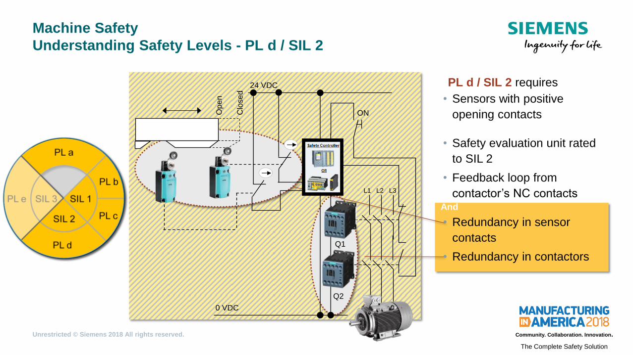
Machine Safety
Understanding Safety Levels - PL d / SIL 2
And
• Sensors with positive
opening contacts
• Safety evaluation unit rated
to SIL 2
• Feedback loop from
contactor’s NC contacts
• Redundancy in sensor
contacts
• Redundancy in contactors
24 VDC
0 VDC
Op
en
Clo
se
d
PL d / SIL 2 requires
ON
L1 L2 L3
Q1
Q2
The Complete Safety Solution

Unrestricted © Siemens 2018 All rights reserved. Community. Collaboration. Innovation.
Machine Safety
Understanding Safety Levels - PL e / SIL 3
And
24 VDC
0 VDC
Op
en
Clo
se
d
ON
L1 L2 L3
Q1
Q2
• Sensors with positive
opening contacts
• Safety evaluation unit rated
to SIL 3
• Feedback loop from
contactor’s NC contacts
• Redundancy in sensor
contacts
• Redundancy in contactors
• Separate channels of
evaluation for sensors
PL e / SIL 3 requires
The Complete Safety Solution
Unrestricted © Siemens 2018 All rights reserved. Community. Collaboration. Innovation.
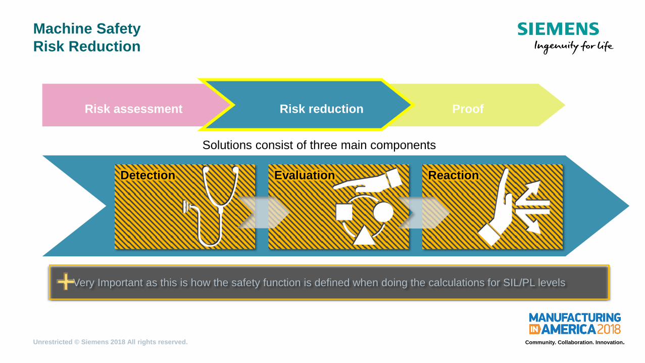
Machine Safety
Risk Reduction
•Solutions consist of three main components
Detection Evaluation Reaction
Risk assessment Risk reduction Proof
Very Important as this is how the safety function is defined when doing the calculations for SIL/PL levels
Unrestricted © Siemens 2018 All rights reserved. Community. Collaboration. Innovation.
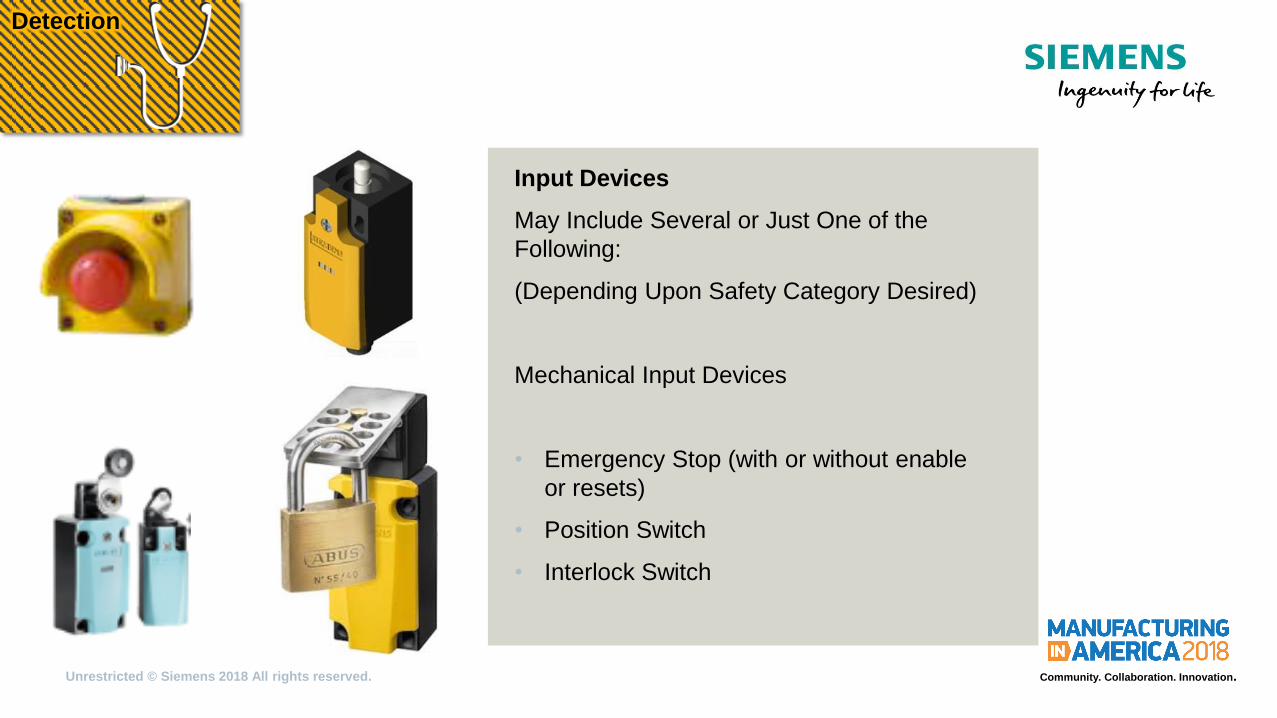
Input Devices
May Include Several or Just One of the
Following:
(Depending Upon Safety Category Desired)
Mechanical Input Devices
• Emergency Stop (with or without enable
or resets)
• Position Switch
• Interlock Switch
Detection
Unrestricted © Siemens 2018 All rights reserved. Community. Collaboration. Innovation.
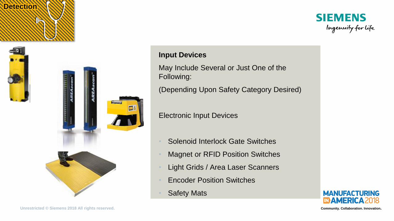
Input Devices
May Include Several or Just One of the
Following:
(Depending Upon Safety Category Desired)
Electronic Input Devices
• Solenoid Interlock Gate Switches
• Magnet or RFID Position Switches
• Light Grids / Area Laser Scanners
• Encoder Position Switches
• Safety Mats
Detection

Unrestricted © Siemens 2018 All rights reserved. Community. Collaboration. Innovation.
Input Devices with Safety Protocol using
Networks
Mixed Safety – Non-Safety Devices same
Network
• AS-I Safe
• Profi Safe
Detection

Unrestricted © Siemens 2018 All rights reserved. Community. Collaboration. Innovation.
Flowchart - Guides you to the right Siemens Safety Solution
To fit your applications safety functionality, as per your comfort level
Detection

Unrestricted © Siemens 2018 All rights reserved. Community. Collaboration. Innovation.
Safety Relay & Programmable
Controllers
May Include One, Several, or a Combination
of the Following:
(Depending Upon Safety Category Desired
and Complexity)
• Safety Relays
• Configurable Safety Relays
• MSS (Modular Safety System)
Evaluation
Unrestricted © Siemens 2018 All rights reserved. Community. Collaboration. Innovation.
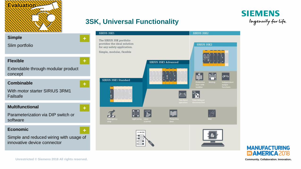
3SK, Universal Functionality
Simple
Slim portfolio
+
Flexible
Extendable through modular product
concept
+
Combinable
With motor starter SIRIUS 3RM1
Failsafe
+
Multifunctional
Parameterization via DIP switch or
software
+
Economic
Simple and reduced wiring with usage of
innovative device connector
+
Evaluation

Unrestricted © Siemens 2018 All rights reserved. Community. Collaboration. Innovation.
Modular expandability of SIRIUS Safety Relays 3SK1
Reduction of wiring outlay and space saving despite higher functionality
Evaluation

Unrestricted © Siemens 2018 All rights reserved. Community. Collaboration. Innovation.
3SK1 compared with 3SK2
3SK1 customer’s requirement 3SK2
most simple logic
more complex logic
additional functions
(e.g. Muting/Interlock)
only wiring allowed
time off delay
complex time functions
powerful outputs
enhanced diagnostics
simplification of commissioning
less space consumption
Evaluation
Unrestricted © Siemens 2018 All rights reserved. Community. Collaboration. Innovation.
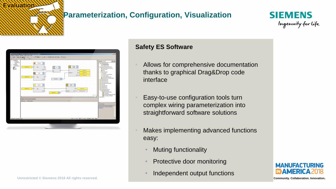
Parameterization, Configuration, Visualization
Safety ES Software
• Allows for comprehensive documentation
thanks to graphical Drag&Drop code
interface
• Easy-to-use configuration tools turn
complex wiring parameterization into
straightforward software solutions
• Makes implementing advanced functions
easy:
• Muting functionality
• Protective door monitoring
• Independent output functions
Evaluation

Unrestricted © Siemens 2018 All rights reserved. Community. Collaboration. Innovation.
Modular Safety System (3RK3)
Designed to minimize the number of
modules needed when multiple safety
functions must be evaluated.
• 3RK3111/3RK3131 (Basic/Advanced
central unit)
• 3RK3121/3RK3122 (Basic/Advanced
central unit with ASI safe integration)
• Expansion modules, DP interface
module, and diagnostic display available
Evaluation
Unrestricted © Siemens 2018 All rights reserved. Community. Collaboration. Innovation.
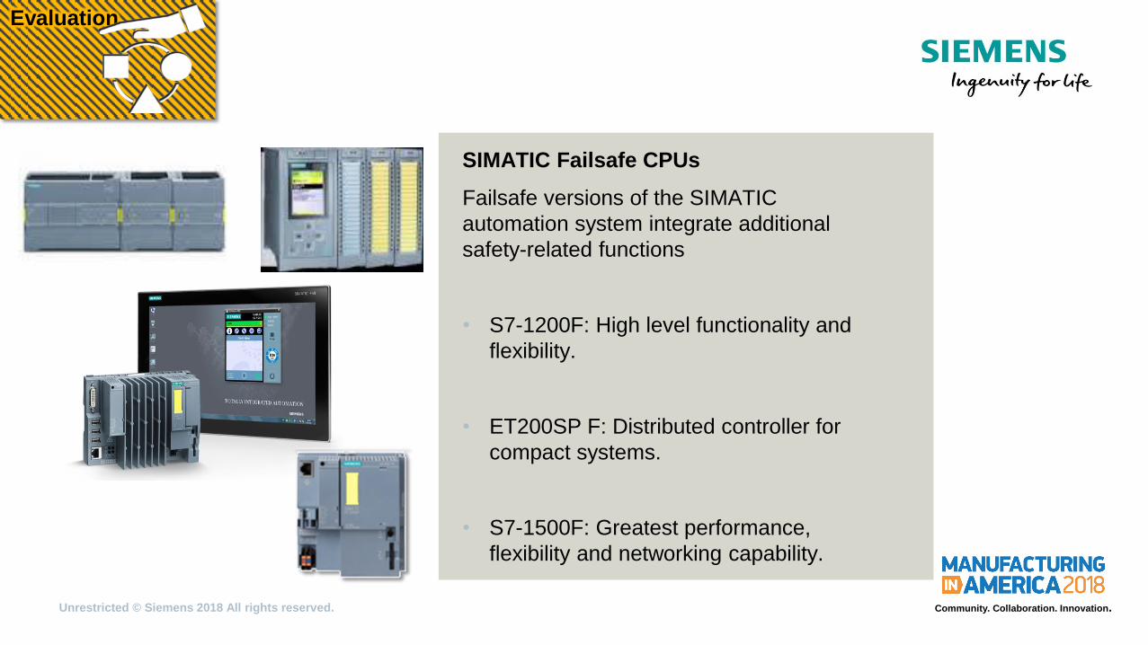
SIMATIC Failsafe CPUs
Failsafe versions of the SIMATIC
automation system integrate additional
safety-related functions
• S7-1200F: High level functionality and
flexibility.
• ET200SP F: Distributed controller for
compact systems.
• S7-1500F: Greatest performance,
flexibility and networking capability.
Evaluation
Unrestricted © Siemens 2018 All rights reserved. Community. Collaboration. Innovation.
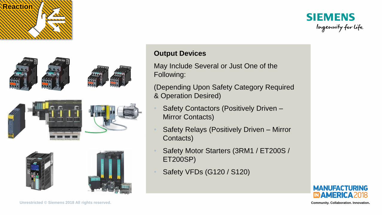
Output Devices
May Include Several or Just One of the
Following:
(Depending Upon Safety Category Required
& Operation Desired)
• Safety Contactors (Positively Driven –
Mirror Contacts)
• Safety Relays (Positively Driven – Mirror
Contacts)
• Safety Motor Starters (3RM1 / ET200S /
ET200SP)
• Safety VFDs (G120 / S120)
Reaction
Unrestricted © Siemens 2018 All rights reserved. Community. Collaboration. Innovation.
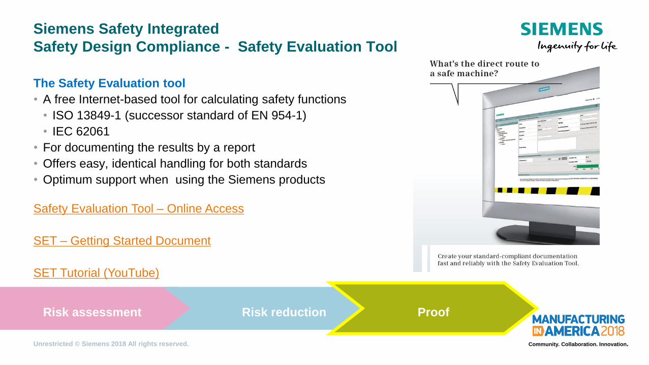
Siemens Safety Integrated
Safety Design Compliance - Safety Evaluation Tool
The Safety Evaluation tool
• A free Internet-based tool for calculating safety functions
• ISO 13849-1 (successor standard of EN 954-1)
• IEC 62061
• For documenting the results by a report
• Offers easy, identical handling for both standards
• Optimum support when using the Siemens products
Safety Evaluation Tool – Online Access
SET – Getting Started Document
SET Tutorial (YouTube)
Risk assessment Risk reduction Proof
Unrestricted © Siemens 2018 All rights reserved. Community. Collaboration. Innovation.
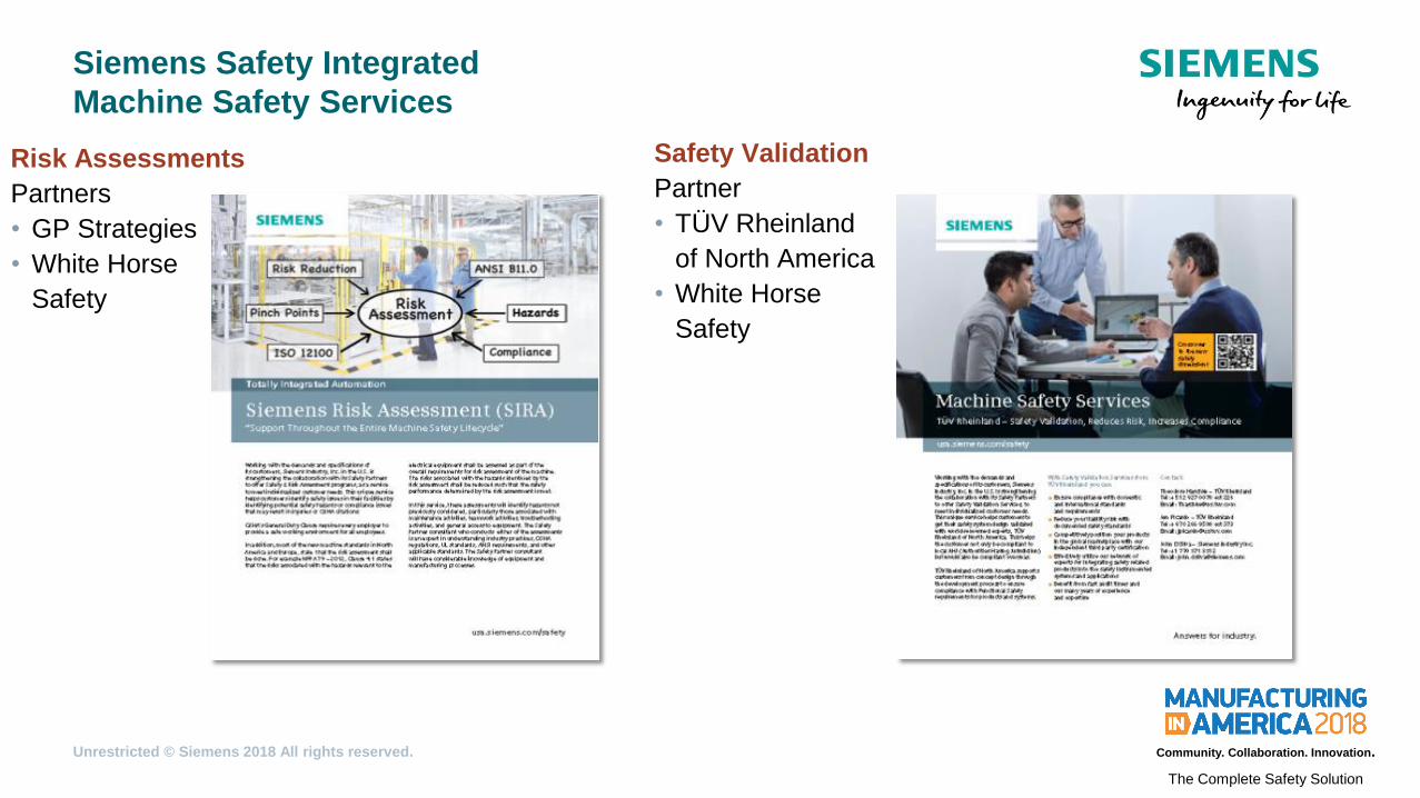
Siemens Safety Integrated
Machine Safety Services
Risk Assessments
Partners
• GP Strategies
• White Horse
Safety
Safety Validation
Partner
• TÜV Rheinland
of North America
• White Horse
Safety
The Complete Safety Solution

Unrestricted © Siemens 2018 All rights reserved. Community. Collaboration. Innovation.
Wheat mill with variable feeding
Requirements
Alternating monitoring of cone or
vessel
manipulation-proof switches
door interlock of service door (crushing
mill)
door interlock of service door (vessel)
nearly no space in cabinet

Unrestricted © Siemens 2018 All rights reserved. Community. Collaboration. Innovation.
Wheat mill with variable feeding
Solution
Solution with HW-parameterized
Safety relays
Solution with SW-parameterized
Safety relays 3SK2

Unrestricted © Siemens 2018 All rights reserved. Community. Collaboration. Innovation.
Wheat mill with variable feeding
Solution
Required 3SK1 Wiring Required 3SK2 Configuration

Unrestricted © Siemens 2018 All rights reserved. Community. Collaboration. Innovation.
Material Feeding System: 3SK2 Example
Inspection Station
Tool Change/Access

Unrestricted © Siemens 2018 All rights reserved. Community. Collaboration. Innovation.
Safety Controls Components: 3SK2 Example
Emergency Stop
- Global
Reset Button
RFID Gate switch
- Safety Motor Starter
Light Curtain
- Contactors
Programmable Safety Relay
Safety Motor Starter
- Conveyor
Contactor
- Robot
Detection Devices Evaluation Devices
Reaction Devices
Unrestricted © Siemens 2018 All rights reserved. Community. Collaboration. Innovation.
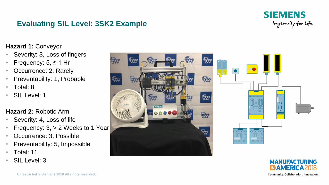
Evaluating SIL Level: 3SK2 Example
Hazard 1: Conveyor
• Severity: 3, Loss of fingers
• Frequency: 5, ≤ 1 Hr
• Occurrence: 2, Rarely
• Preventability: 1, Probable
• Total: 8
• SIL Level: 1
Hazard 2: Robotic Arm
• Severity: 4, Loss of life
• Frequency: 3, > 2 Weeks to 1 Year
• Occurrence: 3, Possible
• Preventability: 5, Impossible
• Total: 11
• SIL Level: 3
Unrestricted © Siemens 2018 All rights reserved. Community. Collaboration. Innovation.
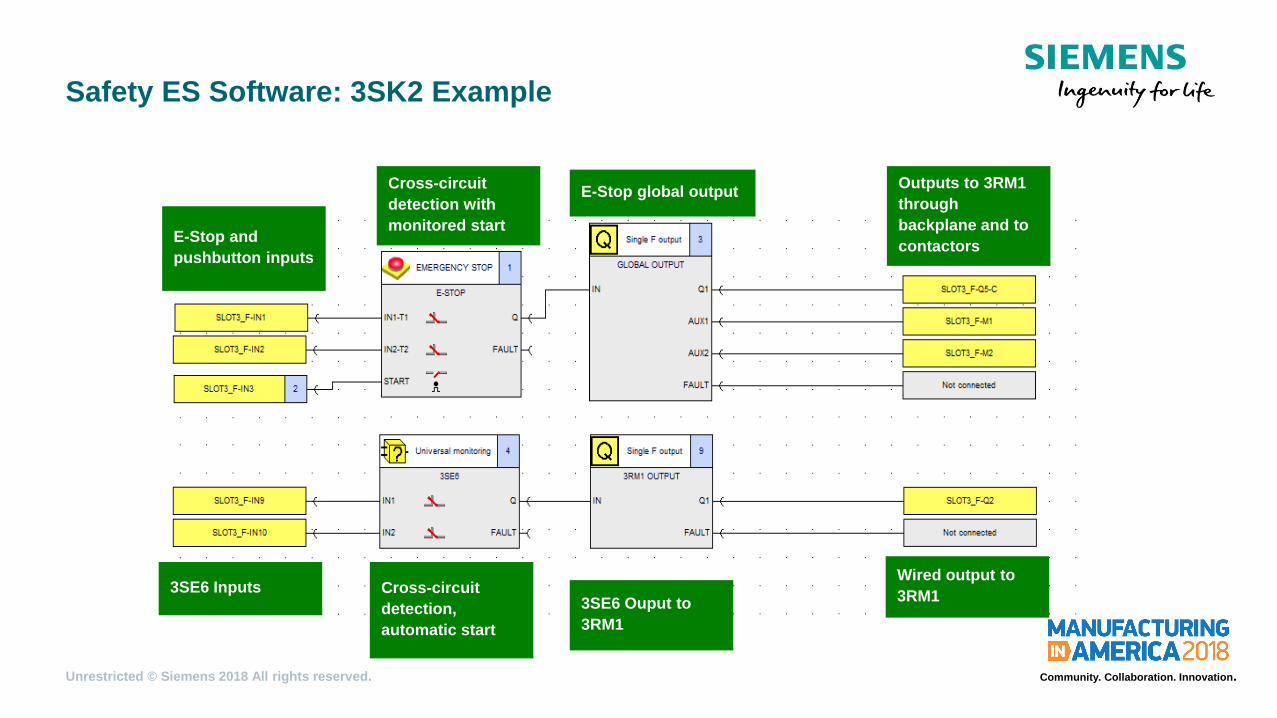
Safety ES Software: 3SK2 Example
Cross-circuit
detection with
monitored start E-Stop and
pushbutton inputs
Outputs to 3RM1
through
backplane and to
contactors
3SE6 Inputs Cross-circuit
detection,
automatic start
3SE6 Ouput to
3RM1
Wired output to
3RM1
E-Stop global output

Unrestricted © Siemens 2018 All rights reserved. Community. Collaboration. Innovation.
Safety ES Software: 3SK2 Example
Inputs from E-stop
output block (M1,
M2) and Light
curtain (M3)
Mirror E-stop condition
output to LED (QM1) and E-
stop and light curtain must
not be tripped for contactor
LED (QM2) to be on
Red E-stop LED
(QM1) Green
contactor LED
(QM2)
Light curtain inputs and push
button inputs, Input from E-
stop output (Q5-C)
Light curtain and E-stop
must not be tripped,
controls contactors Contactor Feedback
Output to
Contactors
Contactors (Q1, Q3)
and Auxiliary to
LED (M3)
Unrestricted © Siemens 2018 All rights reserved. Community. Collaboration. Innovation.
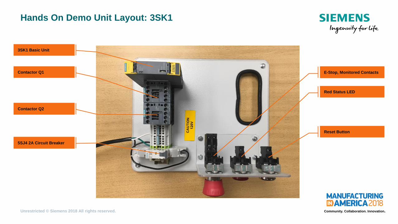
Hands On Demo Unit Layout: 3SK1
3SK1 Basic Unit
Contactor Q1 E-Stop, Monitored Contacts
Red Status LED
Contactor Q2
5SJ4 2A Circuit Breaker
Reset Button

Unrestricted © Siemens 2018 All rights reserved. Community. Collaboration. Innovation.
Task #1: 3SK1 SIL 1 Wiring
The Complete Safety Solution
Goal:
Demonstrate the ease of setup and flexibility of the 3SK1 series with a SIL 1
configuration.
Main take away items:
• Understand the application of SIL 1 safety measures in system design.
• Integrate the 3SK1 into a safety system to satisfy SIL 1 standards.
Unrestricted © Siemens 2018 All rights reserved. Community. Collaboration. Innovation.
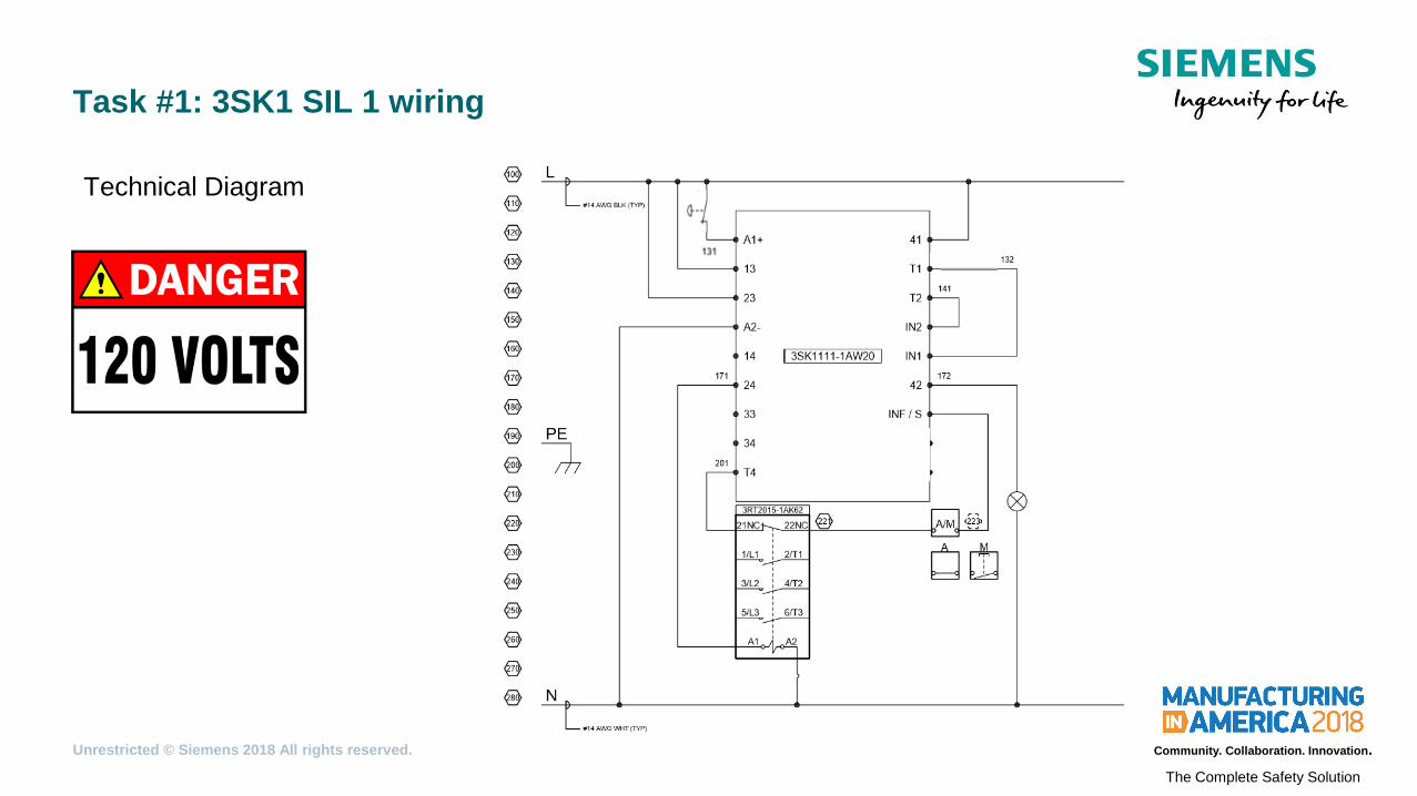
Task #1: 3SK1 SIL 1 wiring
The Complete Safety Solution
Technical Diagram
Unrestricted © Siemens 2018 All rights reserved. Community. Collaboration. Innovation.
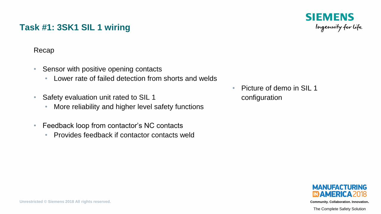
Task #1: 3SK1 SIL 1 wiring
The Complete Safety Solution
Recap
• Sensor with positive opening contacts
• Lower rate of failed detection from shorts and welds
• Safety evaluation unit rated to SIL 1
• More reliability and higher level safety functions
• Feedback loop from contactor’s NC contacts
• Provides feedback if contactor contacts weld
• Picture of demo in SIL 1
configuration
Unrestricted © Siemens 2018 All rights reserved. Community. Collaboration. Innovation.
Task #2: 3SK1 SIL 3 wiring
Goal:
Demonstrate the ease of setup and flexibility of the 3SK1 series with a SIL 3
configuration.
Main take away items:
• Understand the application of SIL 3 safety measures in system design.
• Integrate the 3SK1 into an existing system to satisfy SIL 3 standards.

Unrestricted © Siemens 2018 All rights reserved. Community. Collaboration. Innovation.
Task #3: 3SK1 SIL 3 wiring
The Complete Safety Solution
Technical diagram

Unrestricted © Siemens 2018 All rights reserved. Community. Collaboration. Innovation.
Task #3: 3SK1 SIL 3 wiring
The Complete Safety Solution
Recap
• Safety evaluation unit rated to SIL 3
• More reliability and higher level safety functions
• Separate channels for each set of sensor contacts
• Failure of a single channel does not disable safety
functionality
• Picture of demo in SIL 3
configuration

Unrestricted © Siemens 2018 All rights reserved. Community. Collaboration. Innovation.
How did we do? Share your thoughts to win!
Got 1 minute? Rate this seminar via MiA App for a chance to
win Detroit Tigers tickets:

Unrestricted © Siemens 2018 All rights reserved. Community. Collaboration. Innovation.
Seminar Slides
After MiA, seminar slides will be available at:
http://www.usa.siemens.com/mia-seminars
Unrestricted © Siemens 2018 All rights reserved. Community. Collaboration. Innovation.
Questions?
Robert Jones
6750 Arnold Miller Pkwy
Solon, OH
Phone: (330) 980-1133
E-mail: [email protected]