Embed Size (px)
Citation preview
Laboratory for computer Communications and Applications
(EPFL-I&C-LCA)
Hands-on exercises: IEEE 802.11b
standard
Mario Cagalj Jean-Pierre Hubaux
Imad Aad
{mario.cagalj, jean-pierre.hubaux, imad.aad}@epfl.ch
November 9, 2004
EPFL-I&C-LCA Mobile Networking 1
1 Introduction: IEEE 802.11b standard
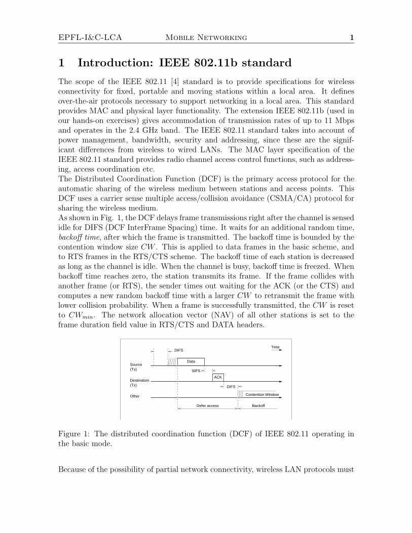
The scope of the IEEE 802.11 [4] standard is to provide specifications for wirelessconnectivity for fixed, portable and moving stations within a local area. It definesover-the-air protocols necessary to support networking in a local area. This standardprovides MAC and physical layer functionality. The extension IEEE 802.11b (used inour hands-on exercises) gives accommodation of transmission rates of up to 11 Mbpsand operates in the 2.4 GHz band. The IEEE 802.11 standard takes into account ofpower management, bandwidth, security and addressing, since these are the signif-icant differences from wireless to wired LANs. The MAC layer specification of theIEEE 802.11 standard provides radio channel access control functions, such as address-ing, access coordination etc.The Distributed Coordination Function (DCF) is the primary access protocol for theautomatic sharing of the wireless medium between stations and access points. ThisDCF uses a carrier sense multiple access/collision avoidance (CSMA/CA) protocol forsharing the wireless medium.As shown in Fig. 1, the DCF delays frame transmissions right after the channel is sensedidle for DIFS (DCF InterFrame Spacing) time. It waits for an additional random time,backoff time, after which the frame is transmitted. The backoff time is bounded by thecontention window size CW . This is applied to data frames in the basic scheme, andto RTS frames in the RTS/CTS scheme. The backoff time of each station is decreasedas long as the channel is idle. When the channel is busy, backoff time is freezed. Whenbackoff time reaches zero, the station transmits its frame. If the frame collides withanother frame (or RTS), the sender times out waiting for the ACK (or the CTS) andcomputes a new random backoff time with a larger CW to retransmit the frame withlower collision probability. When a frame is successfully transmitted, the CW is resetto CWmin. The network allocation vector (NAV) of all other stations is set to theframe duration field value in RTS/CTS and DATA headers.
DIFS
Contention Window
ACK
Data
SIFS
DIFSTime
Source(Tx)
Destination(Tx)
Other
Defer access Backoff
Figure 1: The distributed coordination function (DCF) of IEEE 802.11 operating inthe basic mode.
Because of the possibility of partial network connectivity, wireless LAN protocols must
EPFL-I&C-LCA Mobile Networking 2
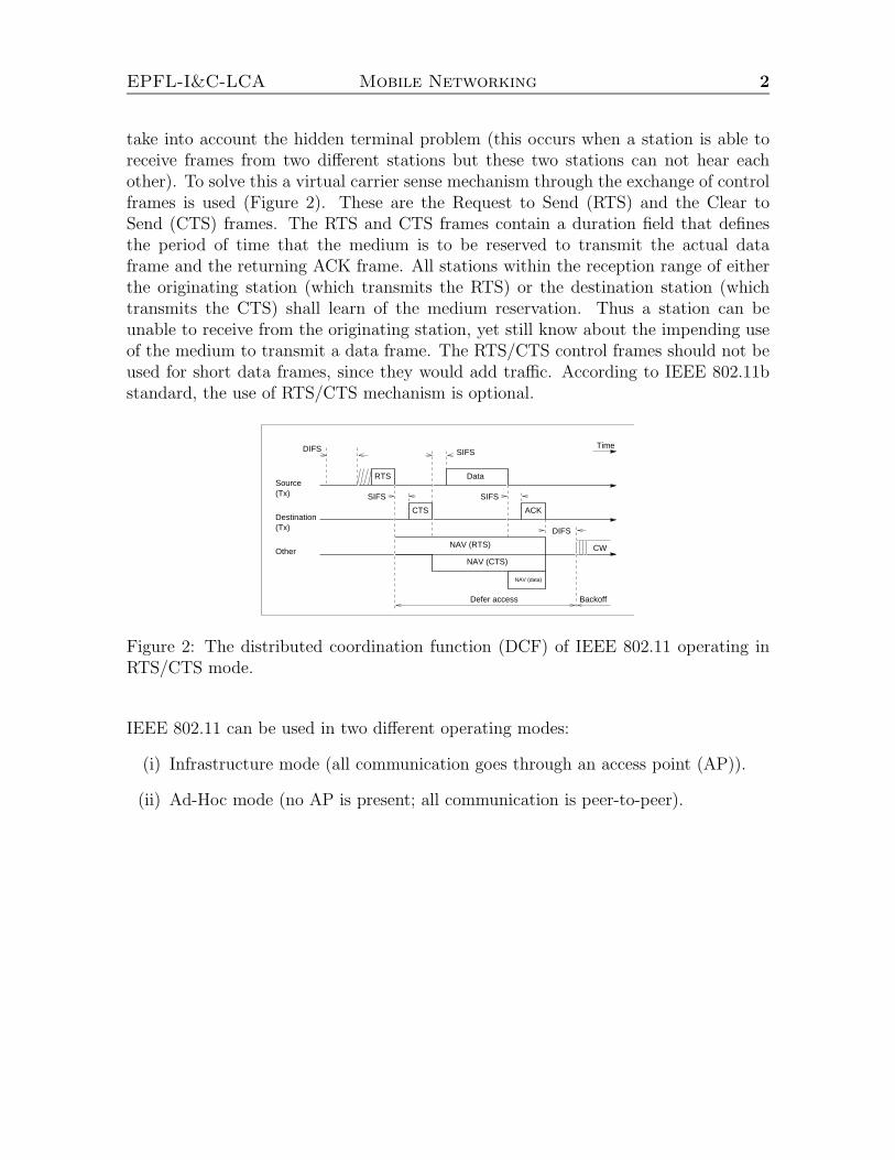
take into account the hidden terminal problem (this occurs when a station is able toreceive frames from two different stations but these two stations can not hear eachother). To solve this a virtual carrier sense mechanism through the exchange of controlframes is used (Figure 2). These are the Request to Send (RTS) and the Clear toSend (CTS) frames. The RTS and CTS frames contain a duration field that definesthe period of time that the medium is to be reserved to transmit the actual dataframe and the returning ACK frame. All stations within the reception range of eitherthe originating station (which transmits the RTS) or the destination station (whichtransmits the CTS) shall learn of the medium reservation. Thus a station can beunable to receive from the originating station, yet still know about the impending useof the medium to transmit a data frame. The RTS/CTS control frames should not beused for short data frames, since they would add traffic. According to IEEE 802.11bstandard, the use of RTS/CTS mechanism is optional.
Defer access
NAV (CTS)
NAV (RTS)
DIFS
CW
Backoff
ACKCTS
Data
SIFS
SIFSTime
RTS
DIFS
Source(Tx)
Destination(Tx)
Other
SIFS
NAV (data)
Figure 2: The distributed coordination function (DCF) of IEEE 802.11 operating inRTS/CTS mode.
IEEE 802.11 can be used in two different operating modes:
(i) Infrastructure mode (all communication goes through an access point (AP)).
(ii) Ad-Hoc mode (no AP is present; all communication is peer-to-peer).
EPFL-I&C-LCA Mobile Networking 3
2 Configuration of wireless client adapters (Infras-
tructure mode)
Our goal in this exercise is to set up an operational Wireless LAN (WLAN). For this, wewill use Cisco Aironet 350 Series Client Adapters available in PCMCIA form. However,in order to plug in the wireless cards to available desktops, we use PCMCIA-to-PCIadapters. Recall that wireless client adapters connect a variety of devices to a wirelessnetwork either in ad hoc peer-to-peer mode or in infrastructure mode with access points(AP).Please note that, once plugged in, the wireless adapters are ready to use, since thedriver is already installed, as well as the client utilities Aironet Client Utility (ACU).Before we proceed, let us just remind that each bench (BANC) comprises two machines,one labeled Router and the other one Station. Please note that in our exercises thereis no difference between the two.Do the following on both, the Station and Router.
Task 1: Minimal configuration
1. Remove any Ethernet cabling
2. Plug in the client wireless adapter. Upon insertion you should get two beeps,confirming that the card is detected and the drivers are loaded successfully.
Task 2: Basic settings
1. Log on to a machine and start an xterm
2. Assign an IP address to the inserted wireless adapter by typing the following:
#ifconfig xxx 192.168.100.abc netmask 255.255.255.0 up
where xxx is the name assigned to the wireless interface (e.g. eth1 for Station;eth2 for Router), and 192.168.100.abc is the IP address assigned to the ma-chine.1 We use the following addressing plan to assign IP addresses to machines.All the machines use 192.168.100 as a common part of their IP address. Thenwe set:
a - to 1 in the case of the Router; to 2 in the case of the Station
bc - to the bench number (e.g. 06 in the case of BANC 6)
1You can learn the identifier assigned to your wireless adapter by typing ifconfig -a at the commandline with the adapter first unplugged and then plugged in.
EPFL-I&C-LCA Mobile Networking 4
3. In the case of the conventional wired networks, once we have interconnected twomachines via a hub and assigned IP addresses to them as above, the machinescan communicate with each other. However, this is not the case with the wirelessIEEE 802.11 protocol. To see this, try to ping one machine from the other one.We will correct this in the task below.
Task 3: Infrastructure modeThis mode is used to set up a connection to a wired network. This mode requires anAccess Point to gain access to the wired part of the network. Note that in InfrastructureMode, an adapter scans frequency channels to find an Access Point. Thus, we do nothave to set the channel by ourselves.
1. Start Aironet Client Utility by typing:
#acu &
Figure 3: Aironet Client Utility (ACU)
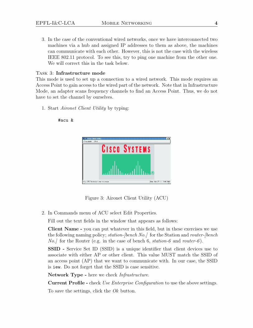
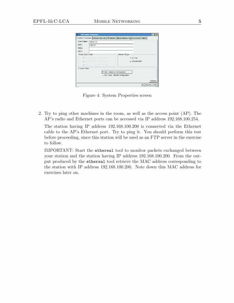
2. In Commands menu of ACU select Edit Properties.
Fill out the text fields in the window that appears as follows:
Client Name - you can put whatever in this field, but in these exercises we usethe following naming policy; station-[bench No.] for the Station and router-[benchNo.] for the Router (e.g. in the case of bench 6, station-6 and router-6 ).
SSID - Service Set ID (SSID) is a unique identifier that client devices use toassociate with either AP or other client. This value MUST match the SSID ofan access point (AP) that we want to communicate with. In our case, the SSIDis iew. Do not forget that the SSID is case sensitive.
Network Type - here we check Infrastructure.
Current Profile - check Use Enterprise Configuration to use the above settings.
To save the settings, click the Ok button.
EPFL-I&C-LCA Mobile Networking 5
Figure 4: System Properties screen
2. Try to ping other machines in the room, as well as the access point (AP). TheAP’s radio and Ethernet ports can be accessed via IP address 192.168.100.254.
The station having IP address 192.168.100.200 is connected via the Ethernetcable to the AP’s Ethernet port. Try to ping it. You should perform this testbefore proceeding, since this station will be used as an FTP server in the exerciseto follow.
IMPORTANT: Start the ethereal tool to monitor packets exchanged betweenyour station and the station having IP address 192.168.100.200. From the out-put produced by the ethereal tool retrieve the MAC address corresponding tothe station with IP address 192.168.100.200. Note down this MAC address forexercises later on.
EPFL-I&C-LCA Mobile Networking 6
WARNING: In order to illustrate security aspects, these exercisesdescribe some techniques aiming at subverting the normal behavior of anetwork. Please note that the usage of these techniques outside of the
scope of the practical exercises is strictly prohibited.
3 Security issues I: passwords sniffing, DoS and
MITM attacks
The goal of this exercise is to raise awareness about vulnerabilities of IEEE 802.11protocol. All the vulnerabilities that we will present here are common to conventionalwired networks. However, the properties of the radio channel makes an attacker morepowerful and harder to detect. Thus, for example, the attacker, in order to sniff a IEEE802.11 traffic, only has to be located somewhere within the communication range ofpossible victims (e.g. at a nearby parking lot).In this exercise we will use a collection of tools for network auditing and penetrationtesting, called dsniff [1]. We will use only one tool out of that collection, namely:arpspoof. This tool is used to poison ARP cache of a machine.Here we do not explore vulnerabilities of WEP (wired equivalent privacy) functionality(a form of data encryption used to scramble the data sent over the radio link). We justmention that tools for breaking the WEP encryption can already be found on the web(e.g. an open source tool WEPCrack).Before we proceed, let us just mention that there are many real life events where theattacks to follow could be easily mounted. Thus, for example, during the course ofmany scientific conferences, the participants are generously offered with a free accessto the Internet via IEEE 802.11b wireless LAN. However, usually no data encryptionis used.In this exercise, an attacking machine will be the laptop with the installed dsniff
collection on it. The desktops available in the lab will play the role of either FTPclient or FTP server (i.e. systems under attack).
Task 1: Passwords sniffing
1. Make both machines of your bench work in the infrastructure mode. Set theirSSID to iew.
2. Start the ethereal tool to monitor packets exchanged during the course of thisexercise.
3. Set up an FTP session between your machine and the FTP server having IPaddress 192.168.100.200. However, when prompted for the user name typeanonymous, while for the password type whatever you want (please make it humanreadable). Are you able to monitor the traffic (non-broadcast) of your neighbors(e.g., with ethereal)?
EPFL-I&C-LCA Mobile Networking 7
4. After you have initialized a session with the FTP server, you do not have todownload anything for an attack to be successful. Thus, just terminate thesession by typing:
ftp> e
5. Finally, you check whether your password has been captured by the attackingmachine or not.
Basically, you have just experienced password sniffing attack. Even though you arenot able to monitor the traffic from other machines in the room, the attacking machineis still able to sniff the traffic. The trick is that the wireless adapter used on theattacking machine is set up to work in the “monitoring” mode. Since the channelis not encrypted, it is straightforward for us to retrieve any interesting information,including your passwords.In the following exercise we will perform the DoS attack, i.e., we will deny the accessto our FTP server. What is interesting with this attack is that all that we need tosuccessfully mount the DoS attack is the IP address of the FTP server, arpspoof tooland of course a wireless adapter. In addition, our attacking machine should within thereception range of the machines under the attack (your own machines).By using arpspoof we will force all the FTP clients to pass their traffic through theattacking machine. This is done by broadcasting fake ARP replay messages that binddifferent IP addresses (one of the FTP server) to the MAC address of the attackingmachine. Finally, to mount the DoS attack the attacking machine simply drops allthe packets arriving at it.
Task 2: DoS attack
1. As in the Task 1, make both machines of your bench work in the infrastructuremode. Set their SSID to iew.
2. Start the ethereal tool to monitor packets exchanged during the course of thisexercise.
3. Check the machines ARP caches occasionally by typing:
# arp -a
Compare the MAC address bound to IP address 192.168.100.200 with the MACaddress of the FTP server 192.168.100.200 as retrieved in the very first exercise(Infrastructure mode). You can also observe fake ARP response packets throughethereal.
EPFL-I&C-LCA Mobile Networking 8
4. Try to set up an FTP session between your machine and the FTP server havingIP address 192.168.100.200. Did you make to get through?
EPFL-I&C-LCA Mobile Networking 9
4 How much do we get out of 11Mbps? (Infras-
tructure mode)
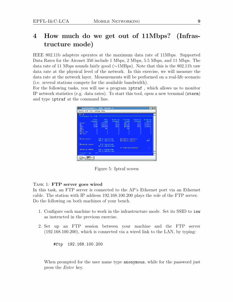
IEEE 802.11b adapters operates at the maximum data rate of 11Mbps. SupportedData Rates for the Aironet 350 include 1 Mbps, 2 Mbps, 5.5 Mbps, and 11 Mbps. Thedata rate of 11 Mbps sounds fairly good (∼1MBps). Note that this is the 802.11b rawdata rate at the physical level of the network. In this exercise, we will measure thedata rate at the network layer. Measurements will be performed on a real-life scenario(i.e. several stations compete for the available bandwidth).For the following tasks, you will use a program iptraf , which allows us to monitorIP network statistics (e.g. data rates). To start this tool, open a new terminal (xterm)and type iptraf at the command line.
Figure 5: Iptraf screen
Task 1: FTP server goes wiredIn this task, an FTP server is connected to the AP’s Ethernet port via an Ethernetcable. The station with IP address 192.168.100.200 plays the role of the FTP server.Do the following on both machines of your bench.
1. Configure each machine to work in the infrastructure mode. Set its SSID to iew
as instructed in the previous exercise.
2. Set up an FTP session between your machine and the FTP server(192.168.100.200), which is connected via a wired link to the LAN, by typing:
#ftp 192.168.100.200
When prompted for the user name type anonymous, while for the password justpress the Enter key.
EPFL-I&C-LCA Mobile Networking 10
3. Before downloading ws-test file to the client, change the local directory the filews-test will be stored to by typing:
ftp> lcd /home/ftp/pub
4. Start the download of the file ws-test as shown below, and observe the data ratewith iptraf. Memorize it for comparison later on.
ftp> get ws-test
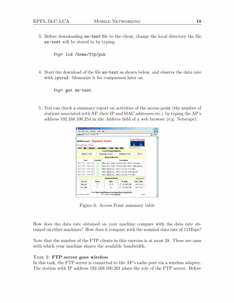
5. You can check a summary report on activities of the access point (the number ofstations associated with AP, their IP and MAC addresses etc.) by typing the AP’saddress 192.168.100.254 in the Address field of a web browser (e.g. Netscape).
Figure 6: Access Point summary table
How does the data rate obtained on your machine compare with the data rate ob-tained on other machines? How does it compare with the nominal data rate of 11Mbps?
Note that the number of the FTP clients in this exercise is at most 28. These are oneswith which your machine shares the available bandwidth.
Task 2: FTP server goes wirelessIn this task, the FTP server is connected to the AP’s radio port via a wireless adapter.The station with IP address 192.168.100.201 plays the role of the FTP server. Before
EPFL-I&C-LCA Mobile Networking 11
proceeding with this task please make sure that the FTP server is connected via theradio channel to the LAN.Do the following on both machines of your bench.
1. Set up an FTP session between your machine and the FTP server(192.168.100.201), which is connected via the radio link to the LAN.
2. Start the download of the file ws-test as shown below, and observe the data ratewith iptraf.
3. As before, you can check a summary report on activities of the access point (thenumber of stations associated with AP, their IP and MAC addresses etc.) bytyping the AP’s address 192.168.100.254 in the Address field of a web browser(e.g. Netscape).
How does the obtained data rate compare with the data rate obtained in the Task 1above? How does it compares with the 11Mbps?
EPFL-I&C-LCA Mobile Networking 12
5 Ad Hoc mode
In the sequel we study the Ad Hoc mode. This mode is used to set up a small,temporary network between two or more computers.
Task 1: Basic configuration
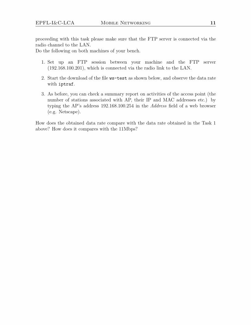
1. In Commands menu of ACU select Edit Properties. Fill out the text fields in the
Figure 7: System Properties screen
window that appears as follows:
Client Name - the same values as for the Infrastructure mode.
SSID - Service Set ID (SSID) is a unique identifier that client devices use toassociate with either AP or other client. This value MUST match the SSID ofany other wireless client that you want to communicate with. In our exercises,we use banc-[bench No.] as the SSID on both, the Station and Router (e.g. forbench 6 we use banc-6 ). Note that the SSID is case sensitive.
Network Type - here we check Ad Hoc.
Current Profile - check Use Enterprise Configuration to use the above settings.
2. In the Ad Hoc mode, the frequency channel must match the channel used by theother Adapters you wish to communicate with. In the window Edit Properties,select the RF Network tab and set the channel your adapter will according to achannel assignment plan2.
In the same window, set Transmit Power to 1mW to reduce the interferencesensed by other adapters; and set Data Rate to 11Mbps.
2You may use any available channel except the channels 1 and 11. This is to prevent interferencewith the EPFL operational network (channels 1 and 11). For example, you can have the bench numberdetermines the channel to be used (benches 1, 11 and 14 should use some other values).

EPFL-I&C-LCA Mobile Networking 13
NOTE: In order to avoid frustrating situations of not being able to change thechannel already assigned to your adapter, try to turn off both the Station’s andRouter’s radios before performing this task (Toggle radio on/off in the menuCommands). It worked with us.
Figure 8: RF Network screen
To save the settings, click the Ok button.
3. Try to ping the Router from the Station and vice versa. Does it work now? Ifyes, congratulation, you have just set up an operational wireless ad hoc network.
IMPORTANT: In this exercise we will again extensively use ws-test file. If for anyreason the size of file is not sufficient, you can generate a new one by running thefollowing script in /home/ftp/pub directory:
#./file-gen
Task 2: How much do we get here out of 11Mbps?
1. Set up an ad hoc network comprising the Station and Router as instructed in theprevious exercise.
2. Next, set up an FTP session between the Station and Router. Since both of themrun an FTP server daemon, it is irrelevant which of the two will play the role ofthe FTP server. In any case, we type at the client:
#ftp 192.168.100._
where 192.168.100._ is the IP address of the FTP server. When prompted forthe user name type anonymous, while for the password just press the Enter key.
EPFL-I&C-LCA Mobile Networking 14
3. Before downloading ws-test file to the client, change the local directory the filews-test will be stored to by typing:
ftp> lcd /home/ftp/pub
4. Start the download of the file ws-test as shown below, and observe the data ratewith iptraf.
ftp> get ws-test
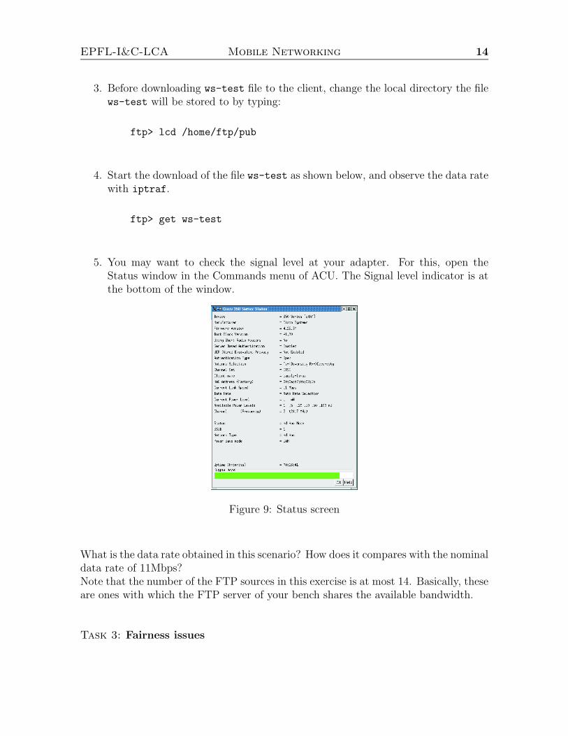
5. You may want to check the signal level at your adapter. For this, open theStatus window in the Commands menu of ACU. The Signal level indicator is atthe bottom of the window.
Figure 9: Status screen
What is the data rate obtained in this scenario? How does it compares with the nominaldata rate of 11Mbps?Note that the number of the FTP sources in this exercise is at most 14. Basically, theseare ones with which the FTP server of your bench shares the available bandwidth.
Task 3: Fairness issues
EPFL-I&C-LCA Mobile Networking 15
1. In this task you should coordinate your activities with the activities of yourcolleagues at a neighboring bench (located either on your left or your right).That is, you should select the same channel as the one of the neighboring bench.
2. In the RF Network window of both the Station and Router, set Transmit Powerto 100mW make sure that you are heard by other stations in the room. Themain reason for doing this is to achieve as symmetric topology as possible. Sincewe are studying fairness, we want each station to experience the same channelconditions.
3. Next, set up an FTP session between the Station and Router at each bench asin Task 2 above. However, here we want a symmetric topology. Thus, given anetwork of four lined up stations, either the two inner stations play the role ofthe FTP servers or the two outer.
4. Start to download the file ws-test simultaneously on both benches and observethe data rates with iptraf (possibly on both machines).
Is IEEE 802.11 fair, that is, is the available bandwidth shared in a fair manner betweenthe FTP servers?Do you have an idea what happens with the capacity of ad hoc networks that useIEEE 802.11 the Distributed Coordination Function (DCF) for sharing the radiochannel, when the number of contending stations increases, given that all the stationsuse the same frequency channel?
EPFL-I&C-LCA Mobile Networking 16
6 Distributed Coordination Function (DCF):
RTS/CTS mechanism
The basic medium access protocol is a DCF that allows sharing of the radio channelthrough the use of CSMA/CA (carrier sense multiple access with collision avoidance)and a random backoff time following a busy medium condition. Carrier sense (CS) isperformed through physical and virtual mechanisms.One means to achieve a virtual carrier sense mechanism is through the exchange ofshort (compared to data frames) RTS/CTS frames. Every RTS/CTS frame containsa network allocation vector (NAV) through which a sender and a designated receiverreserve the radio channel for the exchange of future traffic. Other stations, whenreceiving RTS or CTS frames, regard the radio channel busy for the period specifiedin NAV.The RTS/CTS mechanism is primarily included in the IEEE 802.11 protocol to dealwith the hidden terminal problem. Recall that this problem occurs when a stationis able to receive frames from two different stations but the two station cannot hearsignals from each other. In this case a station may sense the radio channel as beingidle even if the other one is transmitting, which results in a collision at the receivingstation.According to the IEEE 802.11 standard, the use of RTS/CTS mechanism is undercontrol of the RTSThreshold attribute. This mechanism allows a station to beconfigured to use RTS/CTS either always, never, or only on frames longer than aspecified length. When the transmitted packet is equal to or larger than the RTSthreshold, an RTS/CTS mechanism is used.
Task 1: RTS Threshold = max value
1. In this task you should coordinate your activities with the activities of yourcolleagues at a neighboring bench (located either on your left or your right).This is to ensure that at least two servers compete for the available bandwidth.
Set up an ad hoc network comprising the Station and Router. Set the samefrequency channel on both benches.
2. In the RF Network window of both the Station and Router, set Transmit Powerto 100mW.
To save the settings, click the Ok button.
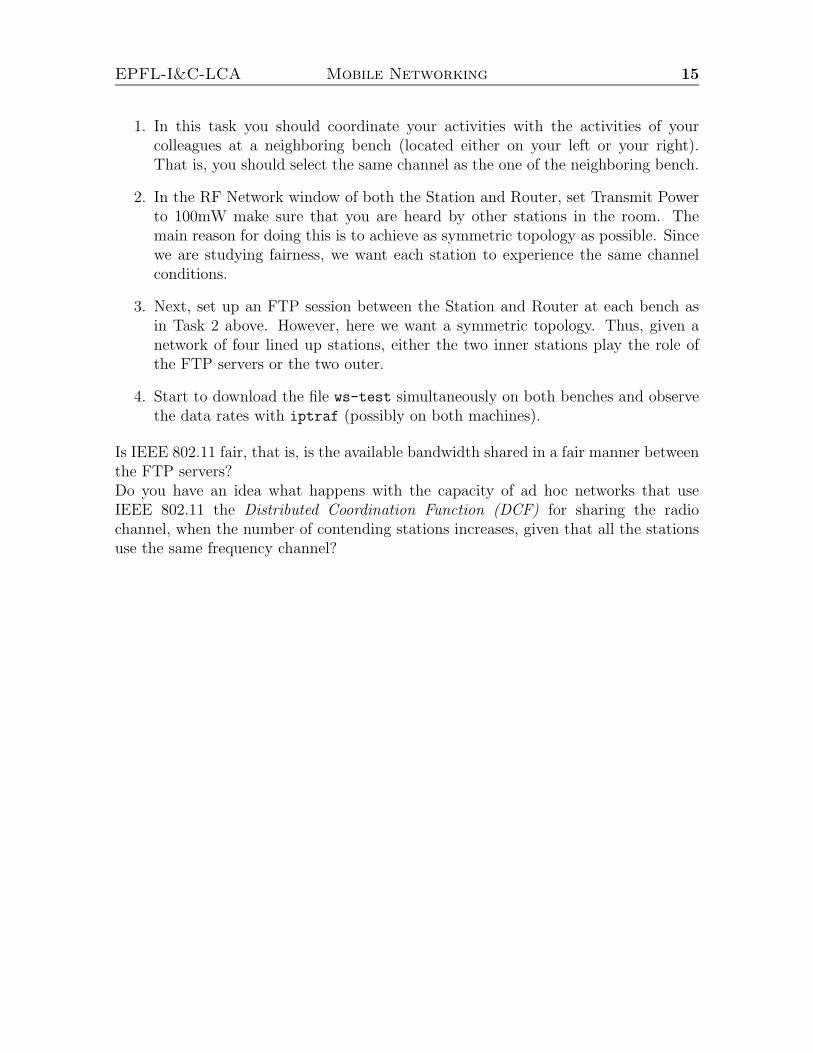
3. Do the following on the FTP servers of both benches. In the Commands menuof ACU, select Edit Properties and select the Advanced AdHoc tab. In theAdvanced AdHoc window, set RTS Threshold to the maximum value (i.e. 2312).
To save the settings, click the Ok button.
EPFL-I&C-LCA Mobile Networking 17
Figure 10: Advanced AdHoc screen
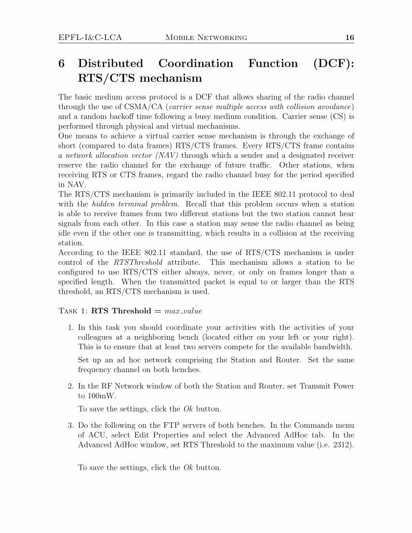
4. Do the following on the FTP servers. In the Commands menu of ACU, selectStatistics to open the Statistics window with the current statistics from the wire-less adapter, including the number of RTS frames transmitted.
Figure 11: Statistics window
NOTE: You can also monitor the number of CTS packet transmitted by the FTPclients.
5. Next, set up an FTP session between the Station and Router on both benches.
6. Before starting to download the file ws-test simultaneously on both benches,press the Reset button in the Statistics window. Observe the data rate withiptraf.
Memorize observed values for the data rate and the number of RTS packet transmittedby the servers.
Task 2: RTS Threshold = small value3 (e.g. 12)
3Do not set this to 0.
EPFL-I&C-LCA Mobile Networking 18
1. Again, you should coordinate your activities with the activities of your colleaguesat a neighboring bench (located either on your left or your right). Do the followingon the FTP servers of both benches. In the Commands menu of ACU, select EditProperties and select the Advanced AdHoc tab. In the Advanced AdHoc window,set RTS Threshold to some value close to 0, but not 0 (e.g. 12).
To save the settings, click the Ok button.
NOTE: You can also monitor the number of CTS packet transmitted by the FTPclients.
2. Do the following on the FTP servers. In the Commands menu of ACU, selectStatistics to open the Statistics window with the current statistics from the wire-less adapter, including the number of RTS frames transmitted.
3. Next, set up an FTP session between the Station and Router on both benches.
4. Before starting to download the file ws-test simultaneously on both benches,press the Reset button in the Statistics window. Observe the data rate withiptraf.
Compare the results obtained in the tasks 1 and 2. Pay particular attention to thedifference in the number of RTS packets transmitted by the FTP servers.How does the number of CTS packets transmitted by FTP clients compare with thenumber of RTS packets transmitted by the corresponding FTP servers?
EPFL-I&C-LCA Mobile Networking 19
7 Routing in mobile ad hoc networks: AODV rout-
ing protocol
The purpose of this exercise is to demonstrate the feasibility of multihop wirelessnetworks. You will also learn a fundamental limitation of multihop wireless networksbased on IEEE 802.11b protocol.Routing algorithms aim at finding a path between a source and a destination stationthat are not necessarily within the reception range of each other. Existing routingprotocols can be classified into two categories:
Proactive routing. Protocols in this category keep track of routes from a sourceto all destination in the network (even if a station will never use some of theroutes). In this way, as soon as a route to a destination is needed, it can beselected in the routing table. The advantages of a proactive protocol are thatcommunication experiences a minimal delay and routes are kept up to date. Thedisadvantages are the additional control traffic and that routes may break, as aresult of mobility, before they are actually used or even that they will never beused at all, since no communication may be needed from a specific source to adestination.
Reactive routing. In contrast to proactive routing protocols, reactive (or on-demand) routing protocols find a path between the source and the destinationonly when the path is needed (i.e., if there are data to be exchanged between thesource and the destination). An advantage of this approach is that the routingoverhead is greatly reduced. A disadvantage is a possible large delay from themoment the route is needed (a packet is ready to be sent) until the time the routeis actually acquired.
The AODV (Ad-Hoc On-Demand Distance Vector) routing protocol [5, 6] is a reactiverouting protocol that uses some characteristics of proactive routing protocols. Routesare established on-demand, as they are needed. However, once established a route ismaintained as long as it is needed.In this exercise we will use the AODV implementation [2] developed at UppsalaUniversity, Sweden. The release we will use is based on AODV draft version 11.
Task 1: Minimal configuration
1. Coordinate your activities with the activities of your colleagues at a neighboringbench (located either on your left or your right) as you are expected to set up anad hoc network of 4 stations.
2. Put your wireless adapter in ad hoc mode. Make sure that you use the samechannel and SSID as your colleagues at the selected bench. Assign an IP addressto your wireless adapter; use the naming convention as specified in Chapter 1.
EPFL-I&C-LCA Mobile Networking 20
3. Open a new terminal window and change your current directory:
#cd /usr/local/aodv-uu-0.6
4. Start the AODV process as follows:
#aodvd -R
5. To check that AODV is successfully run, try to ping other machines in the es-tablished ad hoc network.
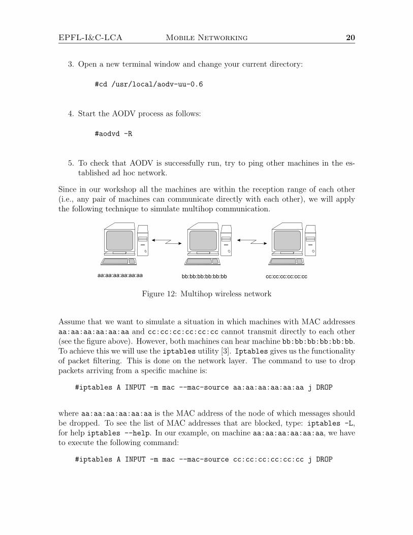
Since in our workshop all the machines are within the reception range of each other(i.e., any pair of machines can communicate directly with each other), we will applythe following technique to simulate multihop communication.
aa:aa:aa:aa:aa:aa bb:bb:bb:bb:bb:bb cc:cc:cc:cc:cc:cc
Figure 12: Multihop wireless network
Assume that we want to simulate a situation in which machines with MAC addressesaa:aa:aa:aa:aa:aa and cc:cc:cc:cc:cc:cc cannot transmit directly to each other(see the figure above). However, both machines can hear machine bb:bb:bb:bb:bb:bb.To achieve this we will use the iptables utility [3]. Iptables gives us the functionalityof packet filtering. This is done on the network layer. The command to use to droppackets arriving from a specific machine is:
#iptables A INPUT -m mac --mac-source aa:aa:aa:aa:aa:aa j DROP
where aa:aa:aa:aa:aa:aa is the MAC address of the node of which messages shouldbe dropped. To see the list of MAC addresses that are blocked, type: iptables -L,for help iptables --help. In our example, on machine aa:aa:aa:aa:aa:aa, we haveto execute the following command:
#iptables A INPUT -m mac --mac-source cc:cc:cc:cc:cc:cc j DROP
EPFL-I&C-LCA Mobile Networking 21
whereas on machine cc:cc:cc:cc:cc:cc we should execute:
#iptables A INPUT -m mac --mac-source aa:aa:aa:aa:aa:aa j DROP
In this way, all the packets sent by machine aa:aa:aa:aa:aa:aa (cc:cc:cc:cc:cc:cc)will be dropped at the MAC layer on machine cc:cc:cc:cc:cc:cc
(aa:aa:aa:aa:aa:aa). Since AODV operates at the network layer, we effec-tively simulate the situation in which the two machines cannot hear each other.As both machines aa:aa:aa:aa:aa:aa and cc:cc:cc:cc:cc:cc hear machinebb:bb:bb:bb:bb:bb, we can use this machine as a forwarding node.
Task 2: 1,2 and 3-hop communication
1. Set up an FTP session between two arbitrary machines from your ad hoc networkover a single hop (you do not need to use the iptables utility here). Downloadthe ws-test file from the selected FTP server and observe the achieved through-put. If the size of ws-test file is not sufficient, you can generate a fresh one byrunning the following script in /home/ftp/pub directory:
#./file-gen
Note down the observed throughput.
2. Set up an FTP session between two arbitrary machines from your ad hoc net-work over 2-hops (use the iptables utility as instructed in the example above).Convince yourself that the communication between the FTP server and the FTPclient goes indeed over 2-hops. For this you may consider using the traceroute
utility or you can simply disconnect the forwarding machine and check if thereis still some traffic between the server and the client. Download the ws-test filefrom the selected FTP server and observe the achieved throughput. Note downthe observed throughput.
3. Set up an FTP session between two arbitrary machines from your ad hocnetwork over 3-hops (make sure that this is indeed the case). Download ws-test
file from the selected FTP server and observe the achieved throughput. Notedown the observed throughput.
Compare the throughputs obtained from the above tests and try to make someconclusions on how the throughput (capacity) scales with the number of hops inIEEE 802.11b multihop networks.
EPFL-I&C-LCA Mobile Networking 22
IMPORTANT: Since only one station can transmit at a time on a common radio chan-nel, it may seem that our “forced” multihop communication greatly underestimatesthe throughput achievable in real multihop scenarios (due to the space diversity; nodesthat cannot hear each other can transmit simultaneously). However, we claim thatthe simulations we are using here match well real multihop scenarios. Can you say why?
Task 3: Route re-establishment
1. Set up an FTP session between two arbitrary machines from your ad hoc networkover 2-hops. Make both remaining machines forwarding nodes (simply startAODV daemon on them). Start to download ws-test file from the selected FTPserver.
2. On the FTP client run:
#traceroute 192.168.100._
where 192.168.100._ is the IP address of the FTP server. From the output pro-duced by the above command, retrieve the IP address of the current forwardingmachine.
3. Disconnect the forwarding machine (e.g., kill the AODV process (CTRL+C) onit) whose IP is retrieved in the previous step. Observe how AODV redirects allthe traffic through the other forwarding node. Try to estimate roughly the timeit takes for this to happen. Has the established FTP session timed out before anew route is acquired?
EPFL-I&C-LCA Mobile Networking 23
Frequently Asked Questions (FAQ) / Troubleshoot-
ing
Q: The network in ad hoc mode is not working.A-1: Check out if you have a FIXED data rate.A-2: Check out if you are using the right/same FREQUENCY at all the stations.
Q: The iptables command is not working.A: Check out if any word is missing. A common mistake is to miss one of the-m mac --mac-source.
Q: How to delete an entry from the iptables ?#iptables -D INPUT 1
(to delete entry 1)
EPFL-I&C-LCA Mobile Networking 24
WARNING: In order to illustrate security aspects, these demos describesome techniques aiming at subverting the normal behavior of a network.Please note that the usage of these techniques outside of the scope of the
practical exercises is strictly prohibited.
8 DEMO: Monitoring IEEE 802.11 traffic and
cheating with IEEE 802.11
This exercise is a demo. In the first part of this exercise we aim to monitor theinterframe spacings and the frame exchanges on the MAC layer. We use Orinoco11a/b/g ComboCards along with their linux driver madwifi. We made this choicefor configurability and monitoring convenience and flexibility. Two machines will beconfigured in monitor mode and station mode respectively.In the second part, we will see how easy is to cheat with the IEEE 802.11 backoffmechanism. We start by transmitting from 2 different stations that use the originaldriver. The monitor is used as in the previous exercise. We then compute the averageobserved backoff of each station as well as its throughput. We proceed to loading amodified driver module into one of the stations. The modified modules “cheat” withthe backoff values. Again, we compute the average observed backoff of each station aswell as its throughput.
Task 1: Monitoring the MAC layerConfigure the monitor station:
1. Load the monitoring driver:
cd PROXIM
make monitor
make monitor loads monitor-driver modules in the card. The driver has beenchanged to support monitor mode.
2. Configure the wireless card:
iwconfig ath0 essid "ws" channel 5
3. Configure and bring the interface up
ifconfig ath0 10.1.1.x up
where x is, for instance, the bench number.
4. Run Ethereal

EPFL-I&C-LCA Mobile Networking 25
Configure the transmitting station:
1. Load the monitoring driver:
cd PROXIM
make nocheat
make nocheat loads the original driver modules in the card.
2. Configure the wireless card:
iwconfig ath0 mode ad-hoc essid "ws" channel 5 rate 11M
3. Configure and bring the interface up
ifconfig ath0 10.1.1.x up
where x is, for instance, the bench number.
4. Use mgen to generate traffic
cd ../MGEN
./mgen input myex.mgn
the input file myex.mgn contains the traffic configuration, e.g.:
0.0 ON 1 UDP SRC 5011 DST 10.1.1.y/5010 PERIODIC [1500 200]
at 0.0 (immediately), turn traffic ON, sending UDP packets, using port 5011, todestination 10.1.1.y, port 5010, PERIODICally. Packet size is 1500, sending rateis 200 packet/s.
5. Observe the monitor output.
6. Now enable RTS/CTS mode
ifconfig ath0 rts 1
7. Observe the monitor output.
8. Figure out how to compute the backoffs ?
Task 1: Cheating on the MAC layerTest 1:
1. Configure the monitor as in the previous exercise

EPFL-I&C-LCA Mobile Networking 26
2. Configure the 2 transmitting stations as in the previous exercise, taking intoaccount that one sends to the other, and vice versa, without using RTS/CTS.
ifconfig ath0 rts off
3. Observe the monitor. Print the “summary” output to a “text” file.
4. Compute the average observed backoff and throughput for each transmittingstation, using awk
awk -f fil-thr.awk mix_nc_nc.tr
awk -f fil-bkf.awk mix_nc_nc.tr
where mix nc nc.tr is the output file from Ethereal
5. Observations ?
Test 2:We will load one card with a “cheated” driver, the other station remains unchanged.
1. Configure the monitor as in the previous exercises
2. Configure one station as in the previous exercises
3. Unload the driver from the other station
cd PROXIM
make clean
4. Load it with a “cheated” driver, with a fixed contention window equal to 1
make 1
5. Go to step 3 of the previous test
6. Observations ?
7. Figure out how to compute backoffs in this case ?
8. Figure out how to detect cheaters ?
9. Figure out what happens when several stations cheat ?
EPFL-I&C-LCA Mobile Networking 27
References
[1] dsniff. http://naughty.monkey.org/∼dugsong/dsniff/.
[2] Implementation of AODV. http://user.it.uu.se/∼henrikl/aodv/index.shtml.
[3] Iptables. http://www.netfilter.org/.
[4] LAN/MAN Standards Committee. ANSI/IEEE Std 802.11:Wireless LAN MediumAccess Control (MAC) and Physical Layer (PHY) Specifications. IEEE ComputerSociety, 1999.
[5] C. Perkins and E. Royer. Ad-Hoc On-Demand Distance Vector Routing. In Pro-ceedings of IEEE WMCSA, 1999.
[6] C. Perkins, E. Royer, and S. Das. Ad hoc On-Demand Distance Vector Routing.IETF MANET Draft, 2002.