Embed Size (px)
Citation preview
International Journal of Computer Science & Information Technology (IJCSIT) Vol 5, No 3, June 2013
DOI : 10.5121/ijcsit.2013.5307 89
HANDOVER MANAGEMENT SCHEME IN LTEFEMTOCELL NETWORKS
Tijane Fatima Zohra BADRI1,2, SAADANE Rachid1,Mohammed Wahbi1
and MbarkiSamir2
1Electrical Engineering DepartmentSIR2C2S/LASI-EHTP Casablanca, morocco2Departement of Computer Science, Faculty of Science LARIT, Ibn Tofail
UniversityKenitra, [email protected]
[email protected][email protected]
ABSTRACT
Femtocell is a small cellular base station in home, a low-power wireless access point designed for use inresidential or small business environment, this technology is a promising solution for operators to improvenetwork performance, and the deployment of a femtocell is a key for bandwidth limitation and coverageissues in conventional mobile network system. Therefore, the inter-cell handover process will become morecomplex, frequent and time-sensitive with the introduction of femtocells in cellular networks. This paperpresents the architecture of LTE femtocell networks and investigates the different scenarios in the handoverprocedure. Especially, the mobility of user from macrocell to femtocell which is quite difficult due to thelarge number of candidate femtocells in the coverage area and the characteristics of the femtocell entity, Inorder to achieve the optimize procedure handover decision policy based on using the advantage of theentity HeNB Policy Function to select and make decision of handover based on different constraint to makethe optimal decision about the target femtocell to mitigate the unnecessary handovers, hence we describethe decision policies rules as well as the handover signalling flow furthermore, an analytical model waspresented for the handover signalling cost.
KEYWORDS
Handover, femtocell, HeNB, macrocell, HeNB policy function, LTE.
1. INTRODUCTION
The concept of mobility offer several advantages to users, they can stay connected by handoversto the cells closer by as they move in the network all the while maintaining their services.Seamless mobility and anywhere anytime type of service provision, have always been key designprinciples for legacy cellular networks, in this work we focus on the mobility management in LTEbased femtocell network.
Femtocell is a small cellular base station designed for use in subscriber’s home and smallbusiness environments. It’s the emerging network technology which is defined broadly as low-cost, low-power cellular base stations [1].
International Journal of Computer Science & Information Technology (IJCSIT) Vol 5, No 3, June 2013
90
The femtocell concept can be applied on different radio access technologies it has been discussedin Long Term Evolution LTE system by the name of Home e-NodeB (HeNB), it also known asfemto access point FAP a main device in femtocell network that provides radio access networkRAN functionality.
The network management and integration of femtocell with LTE macrocell networks is differentfrom the existing LTE networks. Thousands of femtocells inside a macrocell area createinterference problem, also due to huge number of possible target femtocell candidates formacrocell to femtocell handover, a large neighbor list and communication with many femtocellsfor the pre-handover procedure are needed, which may cause signalling overhead andunnecessary handovers. The optimal solution of these two problems can improve the performanceof femtocell networks [2]. In other hand, UEs with high velocities moving through the femtocellusually lead to performing some unnecessary handovers, where an outbound handover happensquickly after an inbound handover, these cause a decreasement of the network performance.Otherwise, another important parameter used in the purpose to protect the rights of the users whoequip a HeNB in their own house and pay for it, the definition of closed subscriber Group (CSG)is proposed in [3]. It identifiessubscribers of an operator who are permitted to access one ormorefemtocells of E-UTRAN but which have restrictedaccess (CSG cells). The definition of CSGgenerates threeaccess modes which allow users to access femtocells, the open access mode, CSGaccess mode and the hybrid access mode.
The open mode designed for public access, the CSG access mode each UE that is not the memberof the CSG is not allowed to access CSG HeNBs noted that UEs hold a whitelist in the USIMcontaining a user controlled list of the allowed CSG identities, finally the Hybrid access same asCSG mode in addition that an UE that is not part of the CSG may camp and receive some level ofservice from the HeNB.
In this paper we overview the architecture of LTE femtocell networks and investigate thedifferent scenarios in the handover procedure specially, the mobility of user from macrocell tofemtocell which is quite difficult due to the large number of candidate femtocells in the coveragearea and the characteristics of the femtocell entity. The handover decision policy is optimized byusing the benefit of the entity HeNBPolicy Function to select and make decision of handoverbased on different constraint to make the optimal choice about the target femtocell.The rest of this paper is organized as follow: In section two we present some research works inhandover management of femtocell networks, in section three we describe the femtocell systemarchitecture in E-UTRAN, in section four we overview the architecture of LTE femtocellnetworks and investigate communication between femtocells and macrocells the differentscenarios in the handover procedure as well as the handover management with the decisionpolicies rules used to select the optimal target femtocell, moreover the signalling flow for theHand-in handover procedure finally an analytical model was presented for the handoversignalling cost evaluation.
2. RELATED WORK
In femtocell network, several research works have been published. In [5], it proposed amobility management scheme that move the mobility anchor for user plane from the S-GW to theHeNB GW and let the HeNB make the handover decision in HeNB- HeNB handover scenario.
The authors in [3] are introduced a call admission control optimization algorithm based onvelocity and the real-timing attribute of the user’s service for femtocell network, However, thealgorithm involved the detection and the judgment of the real timing attribute, which iscomplicated and not suitable for a cost-effective implementation.
International Journal of Computer Science & Information Technology (IJCSIT) Vol 5, No 3, June 2013
91
In [4] it proposed a new Autonomic Architecture with Self-organizing capabilities based on theelection of a Femtocell cluster Head (FH) for each group of Femtocell APs. The FH will beresponsible to dynamically adjust the network overall coverage to save FAP energy and providebetter QoS to users.
More detail works on handover in femtocell network, in [6], it proposed a handover decisionalgorithm that combined the values of received signal strength from a serving macrocell and atarget femtocell in the consideration of large asymmetry in their transmit powers in eNB-to-HeNB handover scenario.
3. FEMTOCELL SYSTEM ARCHITECTURE IN E-UTRAN
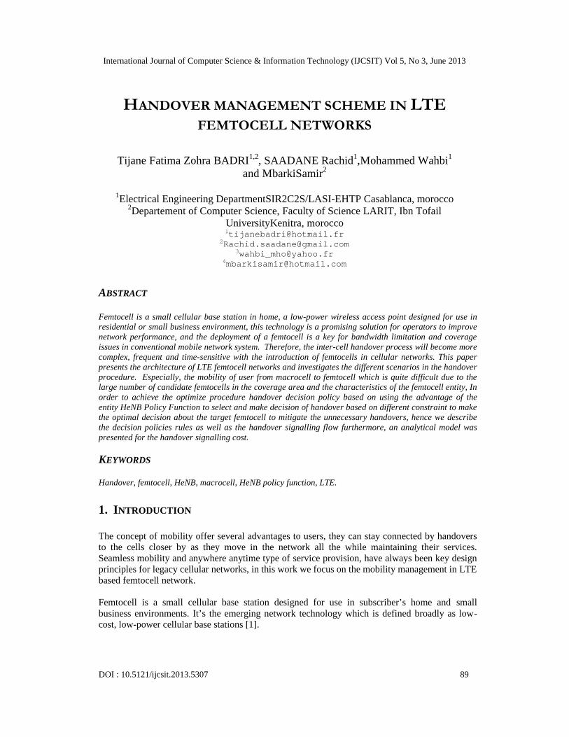
The network architecture of LTE system consists of macrocells with eNodeBs on providing bothuser plane and control plane to the UEs, femtocells being a new addition to the existingcomponents. The eNodeBs are interconnected with each other by the X2 interface which ismainly used for inter-eNodeB handover purpose and also connected to the Mobility ManagementEntity MME which the functions is related to handover and the Serving Gateway (S-GW).TheMobility Management Entity MME is the key control node for the LTE access network thatprocesses the signalling between the UE and the CN, It is also responsible for authenticating theusers and for the generation and allocation of temporary identities to UEs, the MME alsoterminates the S6a interface toward the home HSS for roaming UEs, also handles control planesignalling, especially for mobility management. The S-GW is mobility anchoring for the inter-3GPP mobility and routes and forwards the packet.
Figure 1. The E-UTRAN architecture and the femtocell architecture in E-UTRAN.
As hundreds of thousands of femtocells are deployed, the scalability issue imposes costly re-configuration and operation in MME/S-GW because femtocells use residential broadband as thebackhaul to connect to the mobile core network (CN), security issue needs be considered in orderto protect the integrity of the network from malicious operations. Therefore, the femtocellnetwork needs to consider both of the problems. Figure 1 shows femtocell E-UTRAN architecturewhere femtocell is referred to as Home eNB (HeNB). An intermediate node called HeNBGateway is proposed to be located between HeNBs and the mobile CN. It acts as a “virtual”macro eNodeB towards CN and as a “virtual” CN node towards the HeNBs. Hundreds of HeNBsare connected to the EPC through the HeNB GW; this one should appear to the MME as aneNodeB and appear to the HeNB as an MME between the HeNB and the Core Network. Theinterface between every HeNB ↔ HeNB GW and each HeNB GW↔MME/S-GW is S1 interface,no X2 interface exists between neighboring HeNBs [5].
International Journal of Computer Science & Information Technology (IJCSIT) Vol 5, No 3, June 2013
92
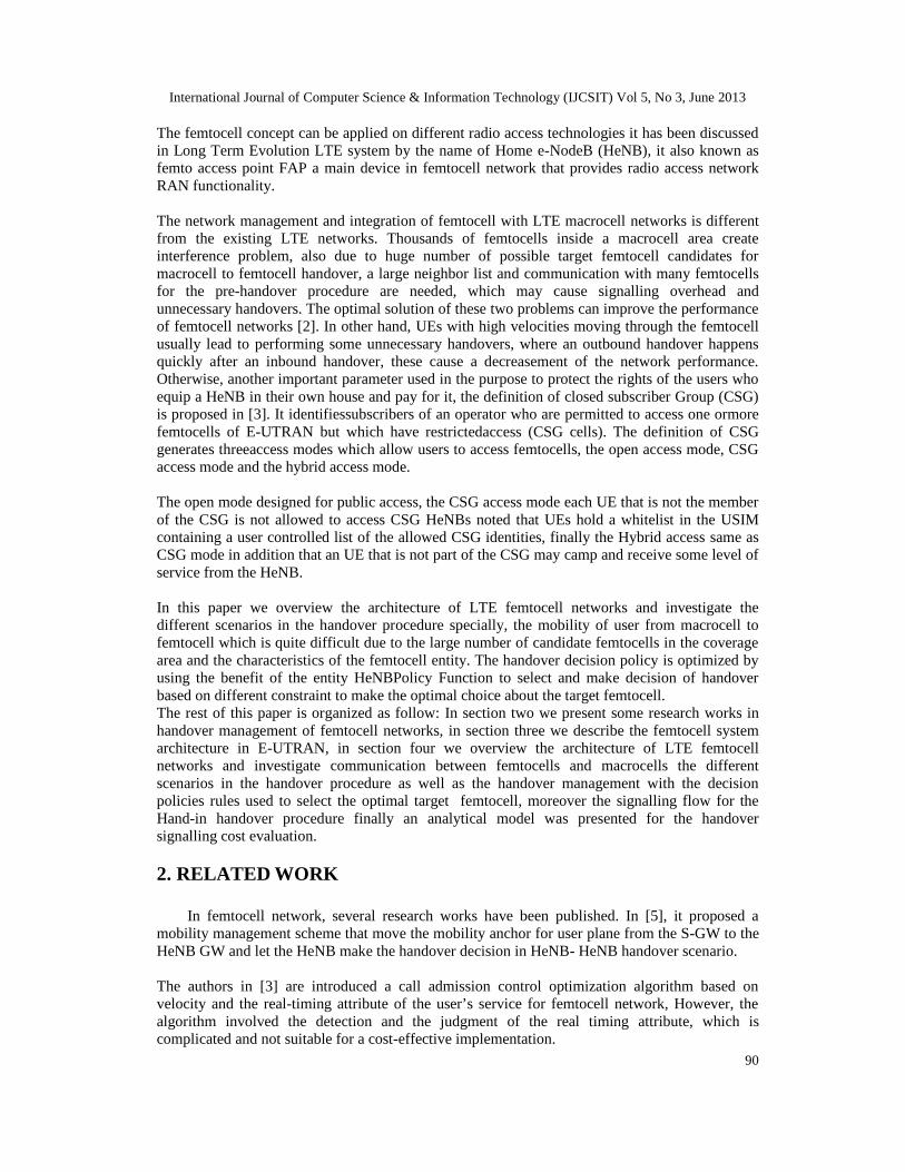
The figure 2 shows the logical architecture of LTE femtocell in 3GPP, which involve the entityHeNB GW acting as the role of concentrator, The HeNB GW entity is assigned with a normaleNodeB ID (a unique identity for an eNodeB among nodes in E-UTRAN) in the purpose to beseen by the MME as any other eNodeBs. The HeNB GW can allocate private identities for eachHeNB within its range and maintain a list of these HeNB IDs, the architecture contain also theHeNB PF for selecting the target femtocell.
The most acting elements in the femtocell logical architecture are the security Gateway (SeGW)who’s responsible for the authentication of femtocell, and providing the femtocell with access tothe HeNB GW, this latter terminates S1 from femtocell and appears as an RNC to the existingcore network using S1 interface, supports femtocell registration and UE registration over S1, andthe HeNB entity provides RAN connectivity using the S1 interface, supports RNC functions,HeNB registration and also supports UE registration over S1 [7]. In other side we have the HeNBPolicy Function HeNB PF which responsible for making decisions according to the characteristicsof HeNB about whether the admission quest can be accepted or rejected interacts with otherpolicy entity like PCRF [8].
Figure 2. Logical architecture for femtocell network.
4. LTE HANDOVER PEROCEDURE AND SIGNALLING FLOW
The handovers allows communication during user’s movement in the network they are used tokeep mobile clients connected to their service network, even when these clients roam from anetwork access point to another network access point, so this procedure is very important formobility support in wireless networks.
In LTE network, the handover decision between two eNodeBs are made by the eNodeBs entityitself without consulting with the MME: the source eNodeB decides to move the UE to the targeteNodeB based on UE measurement report, the target eNodeB prepares radio resources beforeaccepting the handover, after a successful handover, the target eNodeB indicates the sourceeNodeB to release the resources and sends a path switch message to the MME. The latter sends aUser Plane Update Request to the S-GW about to which eNodeB the packets for the user shallroute. The control messages are exchanged via the X2 interface between the two eNodeBs, andthe downlink packet data is also forwarded from the source to the target eNodeBvia the same X2interface [7][8]. The figure 3 illustrates the components of the LTE network architecture withfemtocell integration.
In our procedure, we make use of the entity HeNB PF to make decisions taking the specialelements of femtocell into consideration, user type, access mode, speed status, large amount,small coverage and radio resource control...The aim of using this mechanism to select the targetfemtocell is to avoid some unnecessary handovers which present an important requirement for anefficient handover mechanism. The lower the number of unnecessary handovers the moreefficient the handover mechanism is.
International Journal of Computer Science & Information Technology (IJCSIT) Vol 5, No 3, June 2013
93
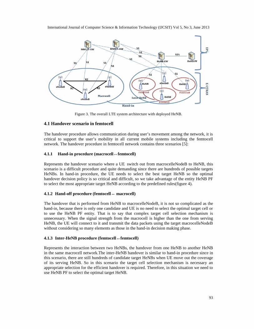
Figure 3. The overall LTE system architecture with deployed HeNB.
4.1 Handover scenario in femtocell
The handover procedure allows communication during user’s movement among the network, it iscritical to support the user’s mobility in all current mobile systems including the femtocellnetwork. The handover procedure in femtocell network contains three scenarios [5]:
4.1.1 Hand-in procedure (macrocell↔femtocell)
Represents the handover scenario where a UE switch out from macrocelleNodeB to HeNB, thisscenario is a difficult procedure and quite demanding since there are hundreds of possible targetsHeNBs. In hand-in procedure, the UE needs to select the best target HeNB so the optimalhandover decision policy is so critical and difficult, so we take advantage of the entity HeNB PFto select the most appropriate target HeNB according to the predefined rules(figure 4).
4.1.2 Hand-off procedure (femtocell↔ macrocell)
The handover that is performed from HeNB to macrocelleNodeB, it is not so complicated as thehand-in, because there is only one candidate and UE is no need to select the optimal target cell orto use the HeNB PF entity. That is to say that complex target cell selection mechanism isunnecessary. When the signal strength from the macrocell is higher than the one from servingHeNB, the UE will connect to it and transmit the data packets using the target macrocelleNodeBwithout considering so many elements as those in the hand-in decision making phase.
4.1.3 Inter-HeNB procedure (femtocell↔femtocell)
Represents the interaction between two HeNBs, the handover from one HeNB to another HeNBin the same macrocell network.The inter-HeNB handover is similar to hand-in procedure since inthis scenario, there are still hundreds of candidate target HeNBs when UE move out the coverageof its serving HeNB. So in this scenario the target cell selection mechanism is necessary anappropriate selection for the efficient handover is required. Therefore, in this situation we need touse HeNB PF to select the optimal target HeNB.
International Journal of Computer Science & Information Technology (IJCSIT) Vol 5, No 3, June 2013
94
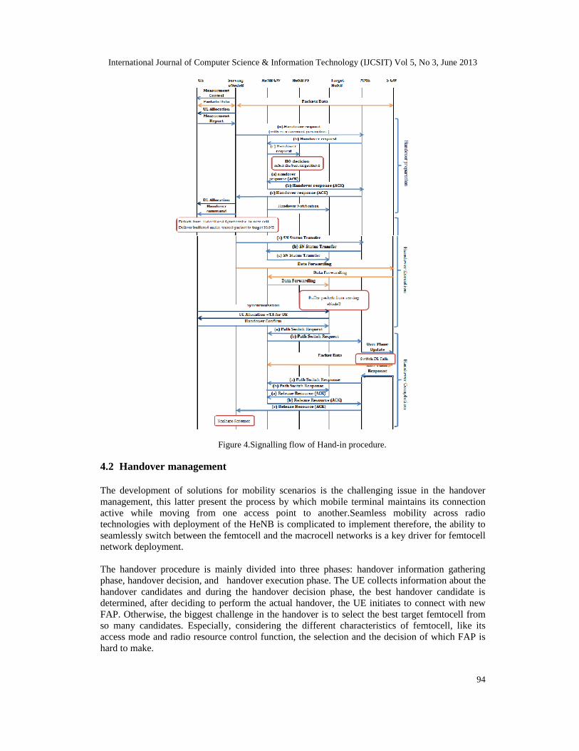
Figure 4.Signalling flow of Hand-in procedure.
4.2 Handover management
The development of solutions for mobility scenarios is the challenging issue in the handovermanagement, this latter present the process by which mobile terminal maintains its connectionactive while moving from one access point to another.Seamless mobility across radiotechnologies with deployment of the HeNB is complicated to implement therefore, the ability toseamlessly switch between the femtocell and the macrocell networks is a key driver for femtocellnetwork deployment.
The handover procedure is mainly divided into three phases: handover information gatheringphase, handover decision, and handover execution phase. The UE collects information about thehandover candidates and during the handover decision phase, the best handover candidate isdetermined, after deciding to perform the actual handover, the UE initiates to connect with newFAP. Otherwise, the biggest challenge in the handover is to select the best target femtocell fromso many candidates. Especially, considering the different characteristics of femtocell, like itsaccess mode and radio resource control function, the selection and the decision of which FAP ishard to make.
International Journal of Computer Science & Information Technology (IJCSIT) Vol 5, No 3, June 2013
95
The handover decision is the most important phase in the handover procedure which containsmeasurements and information about when and where to perform handover and obtained fromone entity or more [4]. We are concerned by the handover decision method to develop thehandover policies in order to optimize the selection of the optimal target femtocell in a way thatmultiple criteria from terminal and network sides and advanced decision is needed, this system isintegrated into the HeNB PF entity.
-Handover Information Gathering. Responsible for collecting all the contextual information,through monitoring and measurements, require to identify the need for handover and to applyhandover decision policies.
- Handover Decision. Defining all requires for the handover (policies) and how to perform it byselecting the most optimal Femtocell based on decision parameters.- Handover Execution.This means establishing the IP connectivity through the target accessfemtocell. For that, we can use fast Mobile IP functionalities as an IP mobility managementsolution.
4.3 Femtocell selection
4.3.1 Handover Policies
The decision policy rules represent a group of parameters and instructions translate scenariosrelated to connectivity, network availability user, or even corporate preferences, in order to beused in femtocell selection step.
The Handover Policies defined as follows: “if condition then action” where the action part istriggered when the condition part is satisfied [4]. For selecting the appropriate femtocell target wemust have some constraint, so we need more decision criteria from the user side as well as fromthe network. The most suitable femtocell, from those available, has to be selected satisfying anumber of objectives.
So, we consider the most dual decisive objectives: The mobility state of UE (speed status) andCSG deployment (CSG ID), a decision making method in which all available alternativesfemtocells are evaluated according to these objectives.
• Mobility state of UE.The states of UE speed should be considered to manage the mobility, toreduce the frequent handover trigger, the ping-ponging effect, so the mobility state of UE effectsdirectly the handover decision.
The traditional handover algorithmlet the high speed macrocell user’s handover to thefemtocell,which may introduce two times unnecessary handovers forthe user. Otherwise, the highspeed macrocell users usually do not want tohandover to the femtocell while the low speed maybe want tohandover to the femtocell but they must satisfying another important criteria the accessmode of the femtocell .
• Access mode of HeNBinfemtocell network. The HeNB is connected to the EPC through aninsecure link, which brings new risks to the LTE network management, the access mode of HeNBmay bring a result that UE isn’t permitted to access the target HeNB selected by serving eNodeBmoreover, the lack of radio resources in the selected cell may cause handover failure too, there arethree types of access mode for the HeNB. The open access mode has no access limits for theusers, the functions supported by a HeNB are similar to those supported by an eNB and theprocedures executed between a HeNB and an EPC are the same as those between an eNB and the
International Journal of Computer Science & Information Technology (IJCSIT) Vol 5, No 3, June 2013
96
EPC so in this mode, if any User Equipment (UE) receives a higher signal level from a specificfemtocell than that from a specific macrocell, it can access the femtocell as long as there issurplus bandwidth.
In the CSG access mode, only the CSG users can be authorized to access it, because the UEs holda whitelist in the USIM containing a user controlled list of the allowed CSG identities. The hybridaccess, this mode is similar to the CSG with the exception that an UE that is not part of the CSGmay camp and receive some level of service from the HeNB, so each femtocell has its CSG userswho are able to access it [9].
Actually, the eNodeB entity can’t obtain such information as access mode and current load of thepossible target HeNBs because there is no interface between them in the current architecture.In order to optimize the efficient of the handover procedure we turn the job of selecting targetfemtocell over to the HeNB PF entity which can interact with the HeNBs and get the HeNBspecial information. In our scheme, the HeNB PF entity uses two aspects of information as inputto make decisions. One is the measurement parameters (Received Signal Strength IndicationRSSI and Interference -and-Noise Ratio INR…) contained in the handover requests and the otheris the HeNB special parameters through the interactions with HeNBs, like its CSG ID, accessmode, speed status, current load, capability and other parameters.
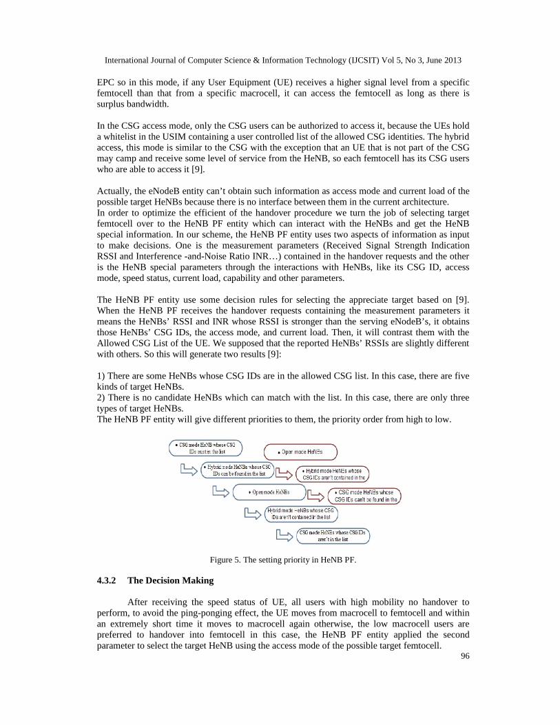
The HeNB PF entity use some decision rules for selecting the appreciate target based on [9].When the HeNB PF receives the handover requests containing the measurement parameters itmeans the HeNBs’ RSSI and INR whose RSSI is stronger than the serving eNodeB’s, it obtainsthose HeNBs’ CSG IDs, the access mode, and current load. Then, it will contrast them with theAllowed CSG List of the UE. We supposed that the reported HeNBs’ RSSIs are slightly differentwith others. So this will generate two results [9]:
1) There are some HeNBs whose CSG IDs are in the allowed CSG list. In this case, there are fivekinds of target HeNBs.2) There is no candidate HeNBs which can match with the list. In this case, there are only threetypes of target HeNBs.The HeNB PF entity will give different priorities to them, the priority order from high to low.
Figure 5. The setting priority in HeNB PF.
4.3.2 The Decision Making
After receiving the speed status of UE, all users with high mobility no handover toperform, to avoid the ping-ponging effect, the UE moves from macrocell to femtocell and withinan extremely short time it moves to macrocell again otherwise, the low macrocell users arepreferred to handover into femtocell in this case, the HeNB PF entity applied the secondparameter to select the target HeNB using the access mode of the possible target femtocell.
International Journal of Computer Science & Information Technology (IJCSIT) Vol 5, No 3, June 2013
97
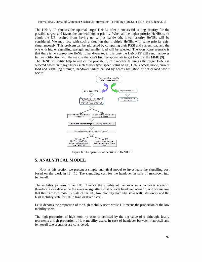
The HeNB PF chooses the optimal target HeNBs after a successful setting priority for thepossible targets and favors the one with higher priority. When all the higher priority HeNBs can’tadmit the UE resulted from having no surplus bandwidth, lower priority HeNBs will beconsidered. We may face with such a situation that multiple HeNBs with same priority existsimultaneously. This problem can be addressed by comparing their RSSI and current load and theone with higher signalling strength and smaller load will be selected. The worst-case scenario isthat there is no appropriate HeNB to handover to, in this case the HeNB PF will send handoverfailure notification with the reasons that can’t find the appreciate target HeNB to the MME [9].The HeNB PF entity help to reduce the probability of handover failure as the target HeNB isselected based on many factors such as user type, speed status of UE, HeNB access mode, currentload and signalling strength, handover failure caused by access limitation or heavy load won’toccur.
Figure 6. The operation of decision in HeNB PF
5. ANALYTICAL MODEL
Now in this section we present a simple analytical model to investigate the signalling costbased on the work in [8] [10].The signalling cost for the handover in case of macrocell intofemtocell.
The mobility patterns of an UE influence the number of handover in a handover scenario,therefore it can determine the average signalling cost of each handover scenario, and we assumethat there are two mobility state of the UE, low mobility state like slow walk, stationary and thehigh mobility state for UE in train or drive a car...
Let α denotes the proportion of the high mobility users while 1-α means the proportion of the lowmobility users.
The high proportion of high mobility users is depicted by the big value of α although, low αrepresents a high proportion of low mobility users. In case of handover between macrocell andfemtocell two scenarios are considered.
International Journal of Computer Science & Information Technology (IJCSIT) Vol 5, No 3, June 2013
98
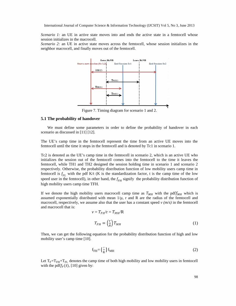
Scenario 1: an UE in active state moves into and ends the active state in a femtocell whosesession initializes in the macrocell.Scenario 2: an UE in active state moves across the femtocell, whose session initializes in theneighbor macrocell, and finally moves out of the femtocell.
Figure 7. Timing diagram for scenario 1 and 2.
5.1 The probability of handover
We must define some parameters in order to define the probability of handover in eachscenario as discussed in [11] [12].
The UE’s camp time in the femtocell represent the time from an active UE moves into thefemtocell until the time it stops in the femtocell and is denoted by Tc1 in scenario 1.
Tc2 is denoted as the UE’s camp time in the femtocell in scenario 2, which is an active UE whoinitializes the session out of the femtocell comes into the femtocell to the time it leaves thefemtocell, while TH1 and TH2 designed the session holding time in scenario 1 and scenario 2respectively. Otherwise, the probability distribution function of low mobility users camp time infemtocell is fFL with the pdf K/t (K is the standardization factor, t is the camp time of the lowspeed user in the femtocell), in other hand, the fFH signify the probability distribution function ofhigh mobility users camp time TFH.
If we denote the high mobility users macrocell camp time as with the pdf which isassumed exponentially distributed with mean 1/µ, r and R are the radius of the femtocell andmacrocell, respectively, we assume also that the user has a constant speed v (m/s) in the femtocelland macrocell that is:
v = /r = /R= (1)
Then, we can get the following equation for the probability distribution function of high and lowmobility user’s camp time [10].
fFH= rR
fMH (2)
Let TF=TFH+TFL denotes the camp time of both high mobility and low mobility users in femtocellwith the pdf ( ), [10] given by:
International Journal of Computer Science & Information Technology (IJCSIT) Vol 5, No 3, June 2013
99
TF(t)=α TFH(t)+(1-α) TFL(t)
fF(t)=α rR
fMH(t)+(1-α)fFL(t) (3)
The form expression of PS1and PS2can be derived as follows [10], where, U is the upper limitationof the femtocell users’ camp time:
Ps1= α Rμrε+Rμ
+(1- α) + eε+KEi(-ε)εK(U-1)
(4)
Ps2= α Rμrε+Rμ
+(1- α) + KEi(-ε) (5)
Where, Ei(x) =∫ 1yey
∞-x dy (6)
TheFTHsi (x) is the cumulative distribution function of TH where i=1,2, and TH follows the
exponentially distributed with the mean of ε, PHsiand PLsiare the probability of high speed users and
low speed users in scenario i (i=1,2) respectively.
5.1.1 The probability of selecting a CSG cell not allowed to access
The probability Ps ofselecting a CSG cell not allowed to access is calculated asfollows [9]:
Pns=Pc*Pncsg/c (7)
With Pc represent the probability that the selected cell is a CSG mode HeNB 0<Pc <1, and thePncsg/c signify the probability that the CSG ID of the selected CSG mode HeNB isn’t in UE’sAllowed CSG list. 0<Pncsg/c<1, as we will never select the CSG cell whose CSG ID isn’t inUE’s Allowed CSG list in our proposal, so Pncsg/c=0 in our scheme.
5.1.2 The probability of selecting a cell which can offer better QoS for UE.
The cells that can offer better QoS for the UE refers to CSGcells whose CSG ID is in UE’sAllowed CSG list and hybridcells whose CSG ID is in UE’s Allowed CSG list. So theprobabilityof selecting a cell which can offer better QoS forUE can be calculated through the expressionbelow [9]:
Ps=Ph*Pcsg/h + Pc*Pcsg/c (8)
With the probability Ph is that the selected cell is a hybrid mode HeNB, 0<Ph<1, otherwise the Pcis probability that the selected cell is a CSG mode HeNB, 0<Pc<1, for the Pcsg/h present theprobability that the CSG ID of the selected hybrid mode HeNB is in UE’s Allowed CSG list,0<Pcsg/h<1.
The probability of the handover happens between the macrocell and femtocell is the sumprobability of scenario 1 Ps1 and scenario 2 Ps2 with the sum probability of selecting a CSG cellnot allowed to access and selecting a cell which can offer better QoS for UE.
PH= (Ps1 + Ps2)*(Ps + Pns) (9)
International Journal of Computer Science & Information Technology (IJCSIT) Vol 5, No 3, June 2013
100
5.2 Cost signalling evaluation
The handover signalling can be divided into transmitting signalling and processing signalling. Sothe transmission cost is the cost of delivering handover message between two nodes andprocessing cost is the cost of processing messages at each node in the network.The signalling costof the HeNB related handover in each scenario is derived as follows:
C=PH (∑Tji+∑ Pk )(10)
Where PH is the probability of the handover in a scenario, and (∑Tji +∑Pk )is the signalling cost.
The signalling cost associated with each handover that is occurred when UE crosses border of two(H) eNBs in active mode is the sum of the transmission cost and processing cost , where iand j indicate nodes in the network, and pair (i, j) indicates the two nodes exchanging thesignalling messages between each other, such as (HeNB, HeNB GW) or (HeNB GW, CN).
6. CONCLUSION
The integration and management of femto-cellular networks with macro-cellular networkspresent the crucial part for the successful deployment of the femtocell technology. However themacrocell into femtocell handover procedure is the most demanding and difficult process, besideit is a challenge to make a selection and decision of the target HeNB, to address this issue, weintend to use the HeNB PF that selects the optimal target HeNB based on the informationincluded in the measurement reports and the special parameters obtained from HeNBs, especiallythe speed status of the UE and the CSG access mode of the Target HeNB in order to protect therights of the users.
REFERENCES
[1] V. Chandrasekhar, J. Andrews, “FemtocellNetwoks : Survey,” IEEE Communication Magazine,Vol.46, No.9, pp59-67, Sept.2008.
[2] Jin-SeokKim,Tae-Jin Lee , “Handover in UMTS Networks with Hybrid Access Femtocells”, the 12thInternational Conference Advanced Communication Technology (ICACT), vol.1, pp.904-907, 7-10Feb.2010.
[3] 3GPP TS 25.367 V9.3.0 (2010-03). “Mobility procedures for Home Node B (HNB); Stage 2. ”[4] K.Sethom Ben Reguiga F. Mhiri ,R.Bouallegue., “Handoff Management in Green FEMTOCELL
Network”, International Journal of Computer Applications (0975 – 8887)Volume 27– No.4, August2011
[5] L. Wang, Y. Zhang, and Z. Wei, “Mobility management schemes at radio network layer for LTEfemtocells,” in IEEE VTC’09, pp. 1–5.
[6] J. M. Moon and D. H. Cho, “Novel handoff decision algorithm in hierarchical macro femto-cellnetworks,” in IEEE WCNC’09.
[7] 3GPP TS 25.467 V9.2.0 (2010-03), “UTRAN architecture for 3G Home Node B (HNB); Stage 2[8] 3GPP TR 23.839 V0.1.1 (2010-05), “Study on Support of BBF Access Interworking”[9] TiantianBai, Yuwei Wang, Yu Liu, Lin ZhangA “Policy-Based Handover Mechanism between
Femtocell and Macrocell for LTE based Networks” 978-1-61284-307-0/11/$26.00 ©2011 IEEE.[10] Haijun Zhang, Wenmin Ma, Wei Li, Wei Zheng, Xiangming Wen Chunxiao Jiang “Signalling Cost
Evaluation of Handover Management Schemes in LTE-Advanced Femtocell” 978-1-4244-8329-7/11/$26.00 ©2011 IEEE
[11] J.S.M. Ho and I. F. Akyildiz, “Local Anchor Scheme for Reducing Signalling Costs in PersonalCommunications Networks”, IEEE/ACM Transactions on networking, Vol 4(5), 1996
[12] ITU-T Recommendation G.114, One-way transmisson time, 2003.