Embed Size (px)
Citation preview

Handbook for Operating a Spectra-PhysicsTM Quanta-Ray
Pro-Series Nd-YAG laser and MOPO-SL (Master Oscillator
Power Oscillator) Utilizing WinSpecTM
Samuel Weisheng Chen
Chemical Science Division
Ernesto Orlando Lawrence Berkeley National Laboratory
Berkeley, CA 94720

DISCLAIMER
This document was prepared as an account of work sponsored by the United States Government. While this document is believed to contain correct information, neither the United States Government nor any agency thereof, nor The Regents of the University of California, nor any of their employees, makes any warranty, express or implied, or assumes any legal responsibility for the accuracy, completeness, or usefulness of any information, apparatus, product, or process disclosed, or represents that its use would not infringe privately owned rights. Reference herein to any specific commercial product, process, or service by its trade name, trademark, manufacturer, or otherwise, does not necessarily constitute or imply its endorsement, recommendation, or favoring by the United States Government or any agency thereof, or The Regents of the University of California. The views and opinions of authors expressed herein do not necessarily state or reflect those of the United States Government or any agency thereof or The Regents of the University of California.
ii

Table of Contents
Map of layout of room 70A-1169B…..………………………………….…… 01
Reference chart on units/crystals needed for MOPO………………………… 01
Turning On Nd-YAG laser…………………………………………………… 02
Turning On MOPO…………………………………………………………… 08
With an FDO at fixed wavelength……………………………………. 09
Without an FDO at fixed wavelength………………………………… 11
Turning On CCD……………………………………………………………… 13
Using WinSpec………………………………………………………………... 15
Setups
Experimental Setup……………………………………………. 17
Repetitive Gating Setup……………………………………….. 19
Sequential Gating Setup………………………………………. 21
Calibration……………………………………………………………... 22
Shutting Down Laser…………………………………………………………… 23
Appendix 1: Glossary…………………………………………………………... 24
Appendix 2: Nd-Yag Power Supply Fuse Positions..…………………………... 26
Appendix 3: Calibration Lines Reference…………………….………………… 27
Appendix 4: Starting Up Cheat Sheet…………………………………………... 29
References…………..…………………………………………………………... 31
Acknowledgement…..…………………………………………………………... 32
iii

• Map of layout of 70A-1169B
Floor Plan: Above is a floor plan of the laser lab. Note that only western half of the room is shown.
• Decide which wavelength is to be used. Refer to chart below on which units/crystals are needed.
Wavelength FDO Crystal Wavelength Type
220.0 – 272.0 nm Yes 56 ° Signal 272.0 – 345.0 nm Yes 36 ° Signal 345.1 – 365.9 nm None -------- --------- 366.0 – 440.0 nm Yes 36 ° Idler 420.0 – 700.0 nm No 36 ° Signal 700.0 – 2200 nm No 36 ° Idler
• Decide if the Frequency Doubling Option (FDO) is to be used. If not, physically remove
the FDO from the laser.
iv

Nd-YAG-laser: 1. Switch door interlock “ON” by depressing the red “ON” button. (See Floor Plan 1 on
pg. 1 and Figure 1)
Figure 1. Door Interlock Panel
2. Open the nitrogen gas supply: blue valve and wheel on gauge (labeled GCR, DCR,
Wex) at right side of the door. (This is usually left open for convenience) (See Floor Plan
2 on pg. 1 and Figure 2)
Figure 2: Location of blue valve for nitrogen supply valve. Usually, this valve is left open for convenience.
v

3. Open the black valve at nitrogen distribution (fixed to copper tubing for water inflow
above backside of optical table). If valve is parallel to the ground, nitrogen valve is closed.
If valve is perpendicular to the ground (pointed to “ON”), valve is on. (This is usually left
open for convenience) (See Floor Plan 3 on pg. 1 and Figure 3)
4. Open the yellow water valve under optical table (valve with pipe marked “IN”) to a 45o-
60o angle. The water serves as a cooling mechanism. The outgoing valve shall be left open
at all times. (See Floor Plan 3 on pg. 1 and Figure 3)
Figure 3: Left shows the relative positions of the nitrogen and water valves. Upper right shows what the nitrogen valve looks
like in the “OFF” position”. Lower right shows what the water valve looks like in the OFF position. Note that the valve in
concern has an “IN” written on it. The “OUT” valve has been taped so that valve is opened at all times.
vi

5. Check the nitrogen flow at gauge on the right side of Nd-YAG laser and adjust to 0.4-
0.6 scfh (standard cubic feet per hour). (See Floor Plan 4 on pg. 1 and Figure 4)
Figure 4: Picture of Nitrogen Distribution Meter.
6. Turn the key on the laser power supply to ON. The switch below the key should always
be left on to warm the crystal. (See Floor Plan 5 on pg. 1 and Figure 5)
Figure 5: Picture of Power Supply and where the key is located. In the above picture, the key is in the OFF position.
vii

7. Turn on the Nd-YAG and MOPO controller (backside). (See Floor Plan 6 on pg. 1
and Figure 6)
Figure 6: Top left shows the front of the Nd-YAG and MOPO. Top right shows the back of the Nd-YAG and MOPO controller
where the ON/OFF switches are located.
8. Press “POWER ON” (hold until beeps) in menu of Nd-YAG controller. “SELF-TEST”
will begin and laser will run in “Q-SWITCH OFF” mode. (See Floor Plan 7 on pg. 1 and
Figure 7 and 8)
Figure 7: Starting menu when the Beamlock controller (i.e. Nd-YAG Controller) is turned on.
Figure 8: Menu that appears after pressing “POWER ON”
9. Let the laser warm up for 10-15 min. (See Floor Plan 7 on pg. 1)
viii

10. Press “RUN LP” (hold until beeps) in menu. Long pulse mode will begin to run. Let the
laser warm up for 20-30 min. (See Figure 9)
Figure 9: Menu after pressing “RUN LP”
11. Press “RUN NORM” (hold until beeps) in menu. Laser will ramp up oscillator and
amplifier, BEAM LOK and D-LOK are checked. If everything is OK the laser will operate.
“PULSE” should be around 1000 units (upper bar scale) under optimal conditions (new
lamps). Expect the maximum “PULSE” to be between 880-1000 units. (See Figure 10)
Figure 10: Picture of a normally operating Nd-YAG Controller. Notice that the “PULSE” is 876, far below the optimum 1000
units.
12. Let laser run for additional 10-15 min. This is for warming up the FDO and MOPO
crystals.
ix

13. Open the Harmonic Generator (HG) lid on the side of the Nd-YAG. Laser emission at
534 nm (UV-Visible) – eye protection !!!! Turn upper screw very careful (only a few
µm) with the pulse reading in sight and optimize pulse. Then turn the lower screw and
optimize. This is to optimize the laser’s FDO position so the maximum power leaving the
Nd-YAG is achieved. Note: Lower screw is more sensitive than upper screw. There is a
slight time delay from turning the screws and the pulse reading on the Beamlock Controller.
(See Floor Plan 8 on pg. 1 and Figure 11)
Figure 11: Left picture shows the location of the hatch containing the Harmonic Generator (HG). Right shows the location of the
screws upon opening the hatch.
x

MOPO: • From Page 1, decide if running with or without FDO. If the FDO needs to be used, place the
prism unit inside the MOPO in the beam path (label: prism active). If the FDO is not to be
used, physically remove the unit. (See Figure 12) Refer to the MOPO-SL manual for more
instructions. When working on the prism, switch Nd-YAG to “Run LP”, or better yet,
“OFF”!!! Eye protection at 1068 nm!!
Figure 12: Shows location of prism that activates the FDO crystal. Note the two parking position of the prism.
xi

With FDO at fixed wavelength 1. Inside the MOPO, physically place the prism into the “Prism Active” position. (See
Figure 12) Note: It is best to have Nd-YAG laser off before removing the FDO unit.
Otherwise, putting the laser under “RUN LP” should be sufficient as long as laser safety
goggles are worn at 1068 nm.
2. On the MOPO controller press “SCAN SETUP” button to “SETUP 1”. This menu
enables you to choose the range in which the target wavelength falls.
3. Choose a “START” and “END” wavelength below and above the target wavelength,
respectively. Input a range where the desired wavelength falls in between. To move the
cursor, press either the “BEGIN” or END” button momentarily. Use the up/down buttons
at far right to change the numbers. (See Figure 13).
Figure 13: Menu that should appear on the MOPO controller after executing Step 2.
4. Press “OPERATE” button to “OPERATE 1”. This menu allows you to set the target
wavelength.
xii

5. Select wavelength with “GOTO” menu button. Move the cursor by momentarily
pressing the “GOTO” button. Use the up and down buttons at far right to change the
numbers.
6. Press and hold until beeps to set.
7. Press “SCAN SETUP” twice to “SETUP 2” menu. This menu will allow you to
maximize the power output of the MOPO at the target wavelength. See Step 8 for details.
You also need to choose the device. (See Figure 14)
Figure 14: Menu that should appear on the MOPO controller after executing Step 5.
8. Press “DEVICE MO-CRYS” and use the up/down keys until the “56o- CRYSTAL”
(signal doubler) or “36o- CRYSTAL” (idler doubler) until beeps. (See Figure 14)
Refer to the chart on Pg. 1 if necessary.
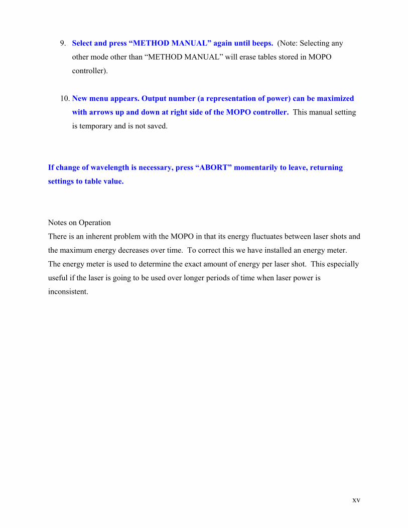
9. Select and press “METHOD MANUAL” again until beeps. (Note: Selecting any
other mode other than “METHOD MANUAL” will erase tables stored in MOPO
controller).
10. New menu appears. Output number (a representation of power) can be maximized
with arrows up and down at right side of the MOPO controller. This manual setting
is temporary and is not saved.
11. If change of wavelength is necessary, press “ABORT” momentarily to leave,
returning settings to table value.
xiii

No FDO: Signal or Idler at fixed wavelength 1. Physically place the prism into the “Prism Park” position. (See Figure 12) This is
because the prism physically blocks the Signal regimes beam path.
Note: It is best to have Nd-YAG laser off before removing the FDO unit. Otherwise,
putting the laser under “RUN LP” should be sufficient as long as laser safety goggles are
worn at 1068 nm.
2. In the monitor menu, select “MOPO TRACK”.
3. Press the “OPERATE” button to “OPERATE 2” menu. Switch to either “MODE
SIGNAL” or “MODE IDLER” depending of frequency you want to look at (refer to
table on pg.1).
4. Choose a “START” and “END” wavelength below and above the target wavelength,
respectively. Input a range where the desired wavelength falls in between. To move the
cursor, press either the “BEGIN” or END” button momentarily. Use the up/down buttons
at far right to change the numbers.
5. Press “OPERATE” button to “OPERATE 1”. This menu allows you to set the target
wavelength.
6. Select wavelength with “GOTO” menu button. Move the cursor by momentarily
pressing the “GOTO” button. Use the up and down buttons at far right to change the
numbers. Press and hold until beeps to set.
7. Press “SCAN SETUP” twice to “SETUP 2” menu. This menu will allow you to
maximize the power output of the MOPO at the target wavelength. See Step 8 for details.
You also need to choose the device
8. Press “MO-CRYSTAL ” until beeps.
xiv
9. Select and press “METHOD MANUAL” again until beeps. (Note: Selecting any
other mode other than “METHOD MANUAL” will erase tables stored in MOPO
controller).
10. New menu appears. Output number (a representation of power) can be maximized
with arrows up and down at right side of the MOPO controller. This manual setting
is temporary and is not saved.
If change of wavelength is necessary, press “ABORT” momentarily to leave, returning
settings to table value.
Notes on Operation
There is an inherent problem with the MOPO in that its energy fluctuates between laser shots and
the maximum energy decreases over time. To correct this we have installed an energy meter.
The energy meter is used to determine the exact amount of energy per laser shot. This especially
useful if the laser is going to be used over longer periods of time when laser power is
inconsistent.
xv

Turning on the CCD Camera Detector Floor Plan
• Turn on following 3 devices in no particular order
• Turn on the transformer located about 50 cm left of the black sample holder box.
(See Detector Floor Plan and Figure 15)
Figure 15: Picture of the transformer. Currently in the “ON” position
xvi

• Turn on the CCD, located behind the Multi-Function Optical Meter. (See Detector
Floor Plan and Figure 16)
Figure 16. Picture of the CCD. The yellow circle highlights the location of the “OFF/ON” switch. Currently the camera is in the
“OFF” position.
• Turn on PTG-Pulser located underneath the table. (See Figure 17)
Figure 17: Picture of the pulser. The yellow circle indicates where the ON/OFF switch is located on the pulser. Currently, the
Pulser is in the OFF position
NOTE: Throughout this manual, the word “camera” and CCD are used interchangeably.
xvii

WinSpec • Open WinSpec, located at Start Program Files Roper Scientific WinSpec32.
• After approximately 15 seconds, the following window should appear. (Figure 17)
Figure 18: Menu seen upon opening WinSpec.
• If not, exit WinSpec, turn off the ST-133 Controller and turn it on again. Open
WinSpec again. If this fails, it is recommended to turn off all CCD related material
(CCD, transformer, and pulser) and reboot the computer.
• Select the appropriate camera state
There are 3 options for the camera state:
a. Keep in Safe Mode
b. Restore to Last Settings
c. Restore Defaults
When in doubt, keep the camera in Safe Mode. This turns off the CCD and prevents
any strong light from damaging the CCD. Restore to Last Settings is used if the
settings (calibration, accumulations, gain, exposures, etc.) are identical to before.
xviii

• Before any optimization can begin, the fluorescence spectrum must be centered.
This can be done by going to Spectrograph Move… (See Figure 19)
Figure 19: Location of moving the grating to center fluorescence spectrum.
• The following screen should appear. Select the appropriate grating the center
wavelength.
Figure 20: Picture of the Move Spectrograph
Grating tells you how large the window is.
300 BLZ = 90 nm on either side of the center (Total window length is 180 nm)
600 BLZ = 44 nm on either side of the center (Total window length is 88 nm)
1200 BLZ = 20 nm on either side of the center (Total window length is 40 nm)
xix

Setups WinSpec offers flexibility when determining the quality of the data collection. Two of the most
used setups menus are “Experimental Setup” and “Pulser…” setup.
Experimental Setup
Experimental Setup is located under Acquisitions Experimental setup (see Figure 21)
Experimental Setup dictates how the computer collects data from the CCD. (See Figure 22)
This differs from Pulser Setup, which is responsible for how the CCD collects the data. (See
Figure 24) Specifically, the Pulser Setup controls the timing issues
Figure 21: Location of Experimental Setup, the menu to access Accumulations, Gain and number of spectra.
xx

Figure 22: Experimental Setup Menu.
xxi
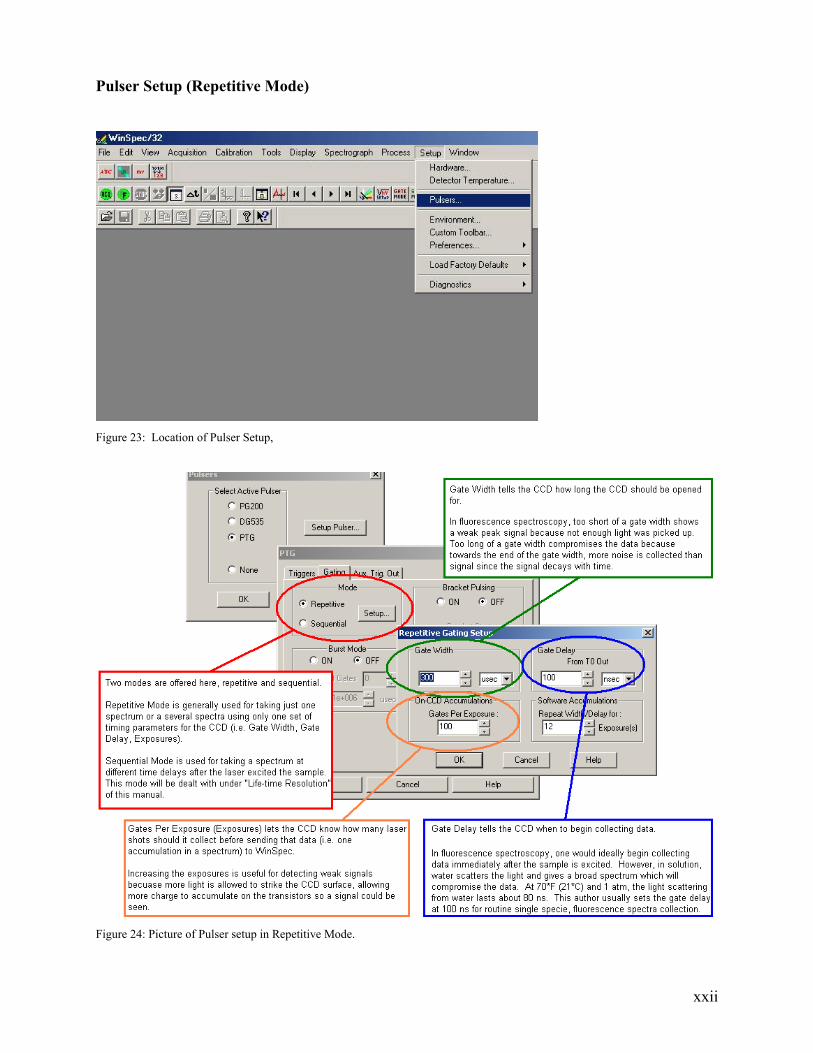
Pulser Setup (Repetitive Mode)
Figure 23: Location of Pulser Setup,
Figure 24: Picture of Pulser setup in Repetitive Mode.
xxii

Useful Hardware Tips for Data Optimization
Since the laser beam has a finite width, it is best to have the at least 1.5 mL of solution in a 1 cm
pathlength cell. Anything less than 1.5 mL has a probability that the full potential of the
fluorescence signal is not exhibited.
The slit is used to control the amount of light entering the monochrometer and an attempt to
make the light a point source. Closing the slit increases the resolution (how detailed/precise the
spectrum is) but dramatically weakens the signal and increases the noise. Opening the slit causes
the peak width to increase and is used for a more accurate quantitative measurement (ex.
complexation constants or concentration measurements).
Figure 25: location of knob controlling the monochrometer.
The slit can be adjusted by a knob found between the black sample box and the monochrometer
(see Figure 25). Each clockwise revolution of the knob represents 250 µm increase in slit width.
According to the manuals, the dispersion is ~1.7 nm. mm-1.
The above suggestions are not hard-and-fast rules, but are a good “rule-of-thumb” estimate. It is
best to take spectrums at different slit width, accumulation, exposures, gains, and concentrations
to optimize spectrum parameters.
xxiii

Pulser Setup (Sequential Mode)
One unique characteristic found within species that fluoresce are their lifetimes. WinSpec offers
an automated lifetime collection which may be found under Setup Pulsers Setup Pulsers.
Under the “Gating” tab, select the “Sequential” mode, and click setup. Below is the WinSpec
Sequential Gating Setup box with a short description what the most commonly used features are.
Figure 26: Picture of Pulser setup in Sequential Mode, generally used for TRLFS.
Note: Be sure to reset the Number of Spectra in the Experimental Section (see Fig. 22) to one (1)
if you revert from TRLFS to a fluorescence spectrum. (Ex. If you do a TRLFS for 24 spectra
(which you typed 24 in the “Number of Spectra” in the Sequential Gating Setup (see Figure 26),
then decide to do a single fluorescence spectrum, be sure to reset the “Number of Spectra” in the
“Experimental Setup” back to one (see Figure 22). Otherwise, when acquiring for the single
fluorescence spectrum, you will be running it for 24 spectra instead of one.)
xxiv

Calibration Depending on the spectrum range, different calibration lamp should be use. Refer to the
WinSpec manual offers an excellent treatise in calibration.
xxv

Shut down: 1. Press “RUN LP” (hold until beeps) in menu, wait 5-10 min. This is critical for the
crystals.
2. Press “Q-SWITCH OFF”, press “LAMP OFF” wait 10-15 min until cooling water
output is cold.
3. Press “POWER OFF”.
4. Switch off Nd-YAG and MOPO controller (backside).
5. Turn key on laser power supply to off. Leave switch below key always on, to heat the
crystals!!!
6. Turn off water and interlock.
7. Let the Nitrogen purge continue for 24 hours before turning off.
Note: Essentially, this is the reverse of the Start Up procedure described in the beginning of the
manual.
Never block the Nd YAG laser beam manually (with shutter, paper). When beam hit
crystals in MOPO without warm up procedure crystals can be damaged !!!!! Always press
“RUN LP” to shut off laser beam and press “ RUN NORM” to start beam.
xxvi

Appendix 1: Glossary
Accumulations How many times the computer receives data from the CCD for one spectrum. Generally,
increasing the accumulations gives a smoother spectrum. (Pg. 17,18) BBO Beta Barium Borate. A nonlinear crystal where by changing the angle, the the resulting
wavelengths change. Camera See CCD Charged Coupling Device (CCD)
Used interchangeably with camera in this manual. A device which accumulates charge on its surface proportional to the amount of light striking it. Excellent for high quality, low noise spectra.
Dispersion Measures ability of monochrometer of resolving two peaks. Exposures Lets the CCD know how many laser shots should be collected before sending the data to
the computer as one accumulation. (Pg. 19) FDO Frequency Doubling Option. Allows the MOPO to operate in the 220-440 nm region. It
literally doubles the Nd-YAG frequency from 534 nm to 267 nm. (Pg. 1, 8-12) Flashlamps In a laser, the lamp which flashes to excite the lasing medium. Fluorescence Type of luminescence. In excited singlet states, the electron in the excited orbital has the
opposite spin of the second electron in the ground state orbital, which is a spin-allowed transition and the emission rate is fast (<1 microsecond).
Gain Acts as a noise discriminator. Gate Delay Tells the CCD when to begin collecting after a laser shot has passed through the sample.
(Pg. 19, 21) Gate Width How long should the camera be opened for each shot. (Pg. 19, 21) Gates Per Exposures See Exposures Gratings Number of diffraction lines per Half life Time it takes for a fluorescence to decay to half of its intensity Idler Wavelength See Signal Wavelength. Interlock Fail-safe pieces of hardware designed to disable the Nd-YAG system should any of the
pieces be defeated. Two general types of interlock, those to protect against intruders (ex. door interlock) and those to protect the equipment (ex. cooling water interlock)
Lifetime Average time it takes for a fluorescence to decay to its ground state Luminescence Emission of light from any substance that occurs when an electron in the excited state
relaxes to the ground state. See phosphorescence and fluorescence. Monochrometer Device used to diffract light and select a small portion of the wavelengths. MOPO Master Oscillator Power Oscillator. Nd-YAG Neodymium - Yttrium Aluminum Garnet. Non-Radiative Transitions
A path for an electronically excited atom or molecule takes to return to the ground state without emitting a photon.
Phosphorescence Type of luminescence. In excited triplet states, the electron in the excited orbital has the same spin as the second electron in the ground state orbital. This is a forbidden transition, so the emission rate is slow (>1 millisecond).
PTG Programmable Timing Generator. See pulser Pulse An arbitrary unit of measurement of the laser’s power. Pulse can be adjusted by two
knobs on the Nd-YAG (Pg. 7) and be affected by warm up time, age of flashlamps, and temperature. (Pg. 6, 7)
Pulser Used interchangeably with PTG. A device used to control timing parameters of the CCD. (Pg. 14, 19)
Quenching A decrease in fluorescence intensity. Wide array of process that causes quenching. Example: when target molecule/element binds with a nonfluorescent compound, when the excited target molecule/element is deactivated from colliding with another compound.
Radiative Transitions A path for an electronically excited atom or molecule takes to return to the ground state by emitting a photon.
Resolution The degree one is able to differentiate two peaks. See Dispersion. scfh Standard cubic feet per hour. Measurement of flow rate at 1 atmosphere pressure and
25ºC. Shots Number of times the laser has fired.
xxvii

Signal Wavelength After the Nd-YAG beam passes through the BBO, two beams of different wavelengths are seen. The beam with the longer wavelength is the Idler Wavelength and the beam with the shorter wavelength is the Signal Wavelength. The summation of the energy of the two beams equals the energy of the Nd-YAG.
Simmer Refers to the flashlamps being in a charged, but idle state. Slit Width How wide the slit is on the monochrometer. The smaller the slit, the better peaks can be
resolved, but the nosier the spectrum gets. (Pg. 20) Spectrum A representation (usually graphical) of characteristics TRLFS Time Resolved Laser Fluorescence Spectroscopy. Technique used to determine number
of species present by discovering how many different lifetimes are present.
xxviii

Appendix 2: Laser Power Supply Fuse Positions Note just the board for the location of the fuses is shown, no other laser components are diagramed The values in bold represent the Ampere value of the fuse in the location
xxix

Appendix 3: Spectral Calibration Lines for Selected Lamps
Above: Calibration lines for pen lamps obtained from http://www.oriel.com/netcat/VolumeIII/pdfs/v39pen.pdf .
xxx
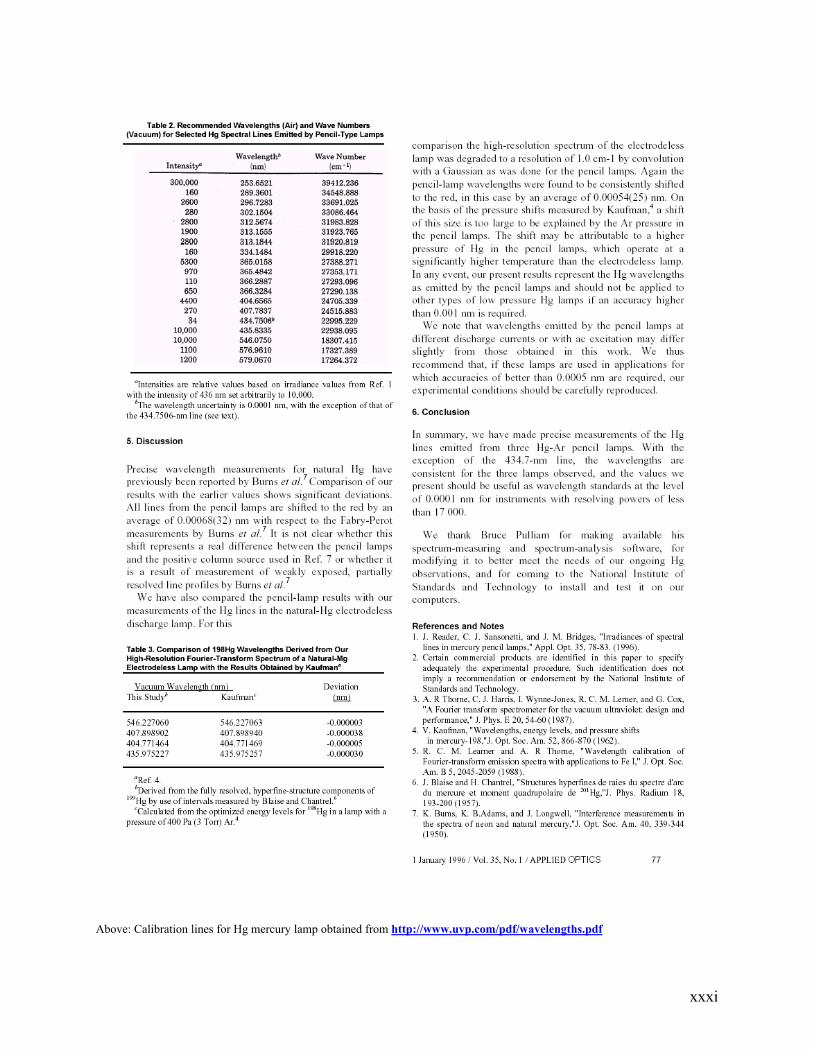
Above: Calibration lines for Hg mercury lamp obtained from http://www.uvp.com/pdf/wavelengths.pdf
xxxi

Appendix 4: Getting Started Cheat Sheet
Getting Started Before turning on the laser be sure to remove any metallic or reflective jewelry including watches, rings, and necklaces, basically anything that could get in the path of the laser and reflect the beam. Please record the number of shots on the flash lamp when you first power up the laser and when you are finished. This should be recorded in the laser lab notebook with the average reading from the power meter, the laser pulse, and the maximum power (the units are arbitrary). Please remember to clean up after your self, this includes appropriately taking care of any waste generated, cleaning out cuvettes, and removing all scratch and other unnecessary papers. Ideally leave the lab cleaner than when you came in, remembering however that this is a shared space and ask before removing or altering an item. Laser Lab Reminders Setup
1) Turn on door interlock system 2) Check that N2 gas valve is on 3) Turn water valve to a 45° angle 4) Check that gas is flowing (0.4-0.6 scfh) 5) Make sure that water is present in the reservoir on the side of the power supply is
between the two level markers during operation. 6) Turn on laser key 7) Turn on MOPO and Nd-YAG box. 8) Press the Nd-YAG “POWER ON” in the front. LET THEM WARM UP FOR 10-15
minutes! 9) Press “RUN LP” and LET IT WARM UP FOR 20-30 min! 10) Press “RUN NORMAL” 11) Adjust the crystal in the laser system (Pulse maximum will be somewhere near
880-1000. Wear laser goggles at 534 nm) 12) LET Nd-YAG WARM UP FOR 30 min! 13) On the MOPO controller under “SETUP 1” enter the BEGIN and END wavelength
that will bracket the target wavelength (ex. if the target wavelength is 410 nm an appropriate start and end points are 380 and 420 nm respectively).
14) Under “OPERATE 1” enter the desired GOTO point. 15) Under “SETUP 2”, choose the appropriate crystal to change. (look at chart in the
FDO manual to determine which device is appropriate under the target wavelength) press and hold. Then press and hold “METHOD MANUAL”. Change the up and down button to maximize the power (13,000-14,000)
xxxii

Reminders When using the laser be sure to save your data and write down all information pertaining to the laser itself and the parameters set for that run including
1) Slit width 2) # of accumulations 3) gain 4) delay 5) exposure 6) width 7) center wavelength of spectrum and the grating number (in BLZ)
Also be sure to write down what the file name is, there are a lot of files on the computer and it makes data analysis simpler. The Nd-YAG laser operates at 1068 and 534nm. Pulse operation 10Hz Pulse duration 12ns Beam energy 3 mJ/cm2 Beam power (upon deliverance) 300,000 kW Average power 30mW Beam diameter ~1cm Beam divergence < 1mrad Resolution ~1.5nm/mm
xxxiii
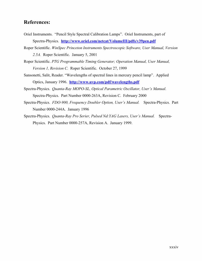
References:
Oriel Instruments. “Pencil Style Spectral Calibration Lamps”. Oriel Instruments, part of
Spectra-Physics. http://www.oriel.com/netcat/VolumeIII/pdfs/v39pen.pdf
Roper Scientific. WinSpec Princeton Instruments Spectroscopic Software, User Manual, Version
2.5A. Roper Scientific. January 5, 2001
Roper Scientific. PTG Programmable Timing Generator; Operation Manual, User Manual,
Version 1, Revision C. Roper Scientific. October 27, 1999
Sansonetti, Salit, Reader. “Wavelengths of spectral lines in mercury pencil lamp”. Applied
Optics, January 1996. http://www.uvp.com/pdf/wavelengths.pdf
Spectra-Physics. Quanta-Ray MOPO-SL, Optical Parametric Oscillator, User’s Manual.
Spectra-Physics. Part Number 0000-263A, Revision C. February 2000
Spectra-Physics. FDO-900, Frequency Doubler Option, User’s Manual. Spectra-Physics. Part
Number 0000-244A. January 1996
Spectra-Physics. Quanta-Ray Pro Serier, Pulsed Nd:YAG Lasers, User’s Manual. Spectra-
Physics. Part Number 0000-257A, Revision A. January 1999.
xxxiv
Acknowledgements
I would like to thank Professor Heino Nitsche, Sarah Herbison, Yung-Jin (Joey) Hu, Richard Wilson, Phil Wilks, and Dianna Jacobs for their help and critique. This work was supported by the Director, Office of Science, Office of Basic Energy Sciences, of the U.S. Department of Energy under Contract No. DE-AC03-76SF00098. 76SF00098.
Date Modified: October 18, 2003 by Samuel Chen
xxxv

xxxvi