Embed Size (px)
Citation preview
Handbook for Biomass Cookstove Research, Design, and Development A PRACTICAL GUIDE TO IMPLEMENTING RECENT ADVANCES
The Global Alliance for Clean Cookstoves is a public-private partnership hosted by the United Nations Foundation that seeks to save lives, improve livelihoods, empower women, and protect the environment by creating a thriving global market for clean and efficient household cooking solutions. The Alliance’s 100 by ’20 goal calls for 100 million households to adopt cleaner and more efficient cookstoves and fuels by 2020. The Alliance is working with its public, private, and non-profit partners to help overcome the market barriers that currently impede the production, deployment, and use of clean cookstoves and fuels in developing countries.
As part of its efforts to create a thriving market for cleaner, more efficient cookstoves and fuels, the Alliance promotes and supports a wide variety of cooking technologies. Different stoves and fuels appeal differently across customer segments and geographies; our goal is to ensure choice, transparency of performance and benefits, as well as availability and affordability of a variety of options, all with the broader goal of ensuring sustained adoption. The Alliance seeks wide accessibility of better cooking products, regardless of stove or fuel type. This handbook is focused on helping to improve the design, usability, and performance of biomass cookstoves.
This material has been funded by UK aid from the UK government; however the views expressed do not necessarily reflect the UK government’s official policies. The authors wish to thank UK aid and take full responsibility for any errors or omissions contained in this handbook.
MIT D-Lab is a university-based program that works with people around the world to develop and advance collaborative approaches and practical solutions to global poverty challenges. The program’s mission is pursued through interdisciplinary courses at the Massachusetts Institute of Technology, trainings around the world in Creative Capacity Building, research in collaboration with global partners, technology development, and community initiatives — all of which emphasize experiential learning, real-world projects, community-led development, and scalability.
TABLE OF CONTENTS
1. Introduction . . . . . . . . . . . . . . . . . . . . . . . . . . . . . . . . . . . 2
1.1 Cookstove Design Ingredients . . . . . . . . . . . . . . . . . . 2
1.2 The Design Process . . . . . . . . . . . . . . . . . . . . . . . . . . . 3
1.3 Performance Testing . . . . . . . . . . . . . . . . . . . . . . . . . . 7
1.4 Important Combustion Concepts . . . . . . . . . . . . . . . . 8
1.5 Types of Biomass Stoves . . . . . . . . . . . . . . . . . . . . . . 10
2. Research & Design Synthesis . . . . . . . . . . . . . . . . . . . . 11
2.1 Ignition . . . . . . . . . . . . . . . . . . . . . . . . . . . . . . . . . . 13
2.2 Air . . . . . . . . . . . . . . . . . . . . . . . . . . . . . . . . . . . . . . 16
2.3 Fuel . . . . . . . . . . . . . . . . . . . . . . . . . . . . . . . . . . . . . 21
2.4 Flame . . . . . . . . . . . . . . . . . . . . . . . . . . . . . . . . . . . . 25
2.5 Mixing . . . . . . . . . . . . . . . . . . . . . . . . . . . . . . . . . . . 29
2.6 Stove Materials . . . . . . . . . . . . . . . . . . . . . . . . . . . . 36
Acknowledgments . . . . . . . . . . . . . . . . . . . . . . . . . . . . . . . 46
References . . . . . . . . . . . . . . . . . . . . . . . . . . . . . . . . . . . . . 47
Appendix: Fuel Types . . . . . . . . . . . . . . . . . . . . . . . . . . . . 50
Endnotes . . . . . . . . . . . . . . . . . . . . . . . . . . . . . . . . . . . . . . 52
1. INTRODUCTION
Biomass cookstove design has been an active field for decades and has resulted in much progress toward cleaner and more efficient cookstoves. However it has been an ongoing challenge to develop high-performing, high-quality products that also satisfy user preferences and are affordable. This can be attributed to several factors:
∙ Design features that improve performance can come with higher costs or require specific cooking practices
∙ Assumption that cookstoves with higher performance must require higher costs, which limits enterprises from considering new designs
∙ Lessons from research and development (R&D) groups have not been well disseminated to enterprises producing stoves
∙ Enterprises have expressed interest in improving their technologies, but have limited expertise and resources for R&D
This handbook presents insights and methodologies from recent R&D programs at multiple institutions to achieve higher performance, lower cost, and improved usability. This handbook will help cookstove designers and enterprises to integrate the latest R&D innovations into their products and support further innovation.
Burning fuel and cooking are complicated and this handbook is meant to stimulate curiosity. We refer readers to the references (Table 1 on page 4) to more fully understand how these innovations can be incorporated into their products.
1.1 COOKSTOVE DESIGN INGREDIENTS
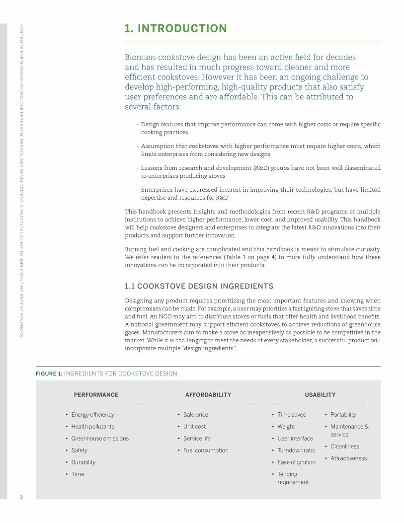
Designing any product requires prioritizing the most important features and knowing when compromises can be made. For example, a user may prioritize a fast igniting stove that saves time and fuel. An NGO may aim to distribute stoves or fuels that offer health and livelihood benefits. A national government may support efficient cookstoves to achieve reductions of greenhouse gases. Manufacturers aim to make a stove as inexpensively as possible to be competitive in the market. While it is challenging to meet the needs of every stakeholder, a successful product will incorporate multiple “design ingredients.”
FIGURE 1: INGREDIENTS FOR COOKSTOVE DESIGN
PERFORMANCE
• Energy efficiency
• Health pollutants
• Greenhouse emissions
• Safety
• Durability
• Time
AFFORDABILITY
• Sale price
• Unit cost
• Service life
• Fuel consumption
USABILITY
• Time saved
• Weight
• User interface
• Turndown ratio
• Ease of ignition
• Tending requirement
• Portability
• Maintenance & service
• Cleanliness
• Attractiveness
HA
ND
BO
OK
FOR
BIO
MA
SS
CO
OK
ST
OV
E R
ES
EA
RC
H, D
ES
IGN
, AN
D D
EV
ELO
PM
EN
T: A
PR
AC
TIC
AL G
UID
E T
O IM
PL
EM
EN
TIN
G R
EC
EN
T A
DV
AN
CE
S
2
1.2 THE DESIGN PROCESS
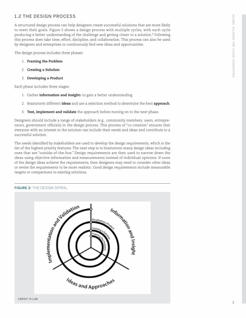
A structured design process can help designers create successful solutions that are more likely to meet their goals. Figure 2 shows a design process with multiple cycles, with each cycle producing a better understanding of the challenge and getting closer to a solution.1 Following this process does take time, effort, discipline, and collaboration. This process can also be used by designers and enterprises to continuously find new ideas and opportunities.
The design process includes three phases:
1. Framing the Problem
2. Creating a Solution
3. Developing a Product
Each phase includes three stages:
1. Gather information and insights to gain a better understanding
2. Brainstorm different ideas and use a selection method to determine the best approach.
3. Test, implement and validate the approach before moving on to the next phase.
Designers should include a range of stakeholders (e.g., community members, users, entrepre-neurs, government officials) in the design process. This process of “co-creation” ensures that everyone with an interest in the solution can include their needs and ideas and contribute to a successful solution.
The needs identified by stakeholders are used to develop the design requirements, which is the list of the highest priority features. The next step is to brainstorm many design ideas including ones that are “outside-of-the-box.” Design requirements are then used to narrow down the ideas using objective information and measurements instead of individual opinions. If none of the design ideas achieve the requirements, then designers may need to consider other ideas or revise the requirements to be more realistic. Good design requirements include measurable targets or comparisons to existing solutions.
FIGURE 2: THE DESIGN SPIRAL
CREDIT: D-LAB
GLO
BA
L AL
LIA
NC
E FO
R C
LE
AN
CO
OK
ST
OV
ES
3
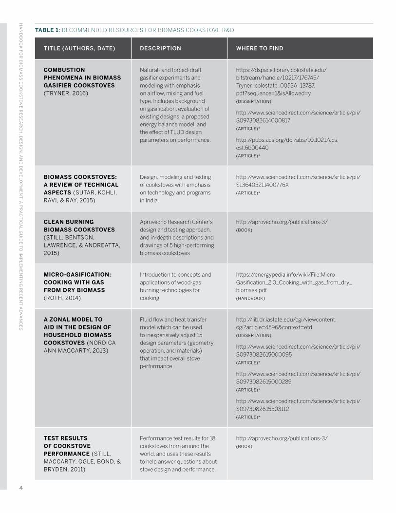
TABLE 1: RECOMMENDED RESOURCES FOR BIOMASS COOKSTOVE R&D
TITLE (AUTHORS, DATE) DESCRIPTION WHERE TO FIND
COMBUSTION PHENOMENA IN BIOMASS GASIFIER COOKSTOVES (TRYNER, 2016)
Natural- and forced-draft gasifier experiments and modeling with emphasis on airflow, mixing and fuel type. Includes background on gasification, evaluation of existing designs, a proposed energy balance model, and the effect of TLUD design parameters on performance.
https://dspace.library.colostate.edu/bitstream/handle/10217/176745/Tryner_colostate_0053A_13787.pdf?sequence=1&isAllowed=y (DISSERTATION)
http://www.sciencedirect.com/science/article/pii/S0973082614000817 (ARTICLE)*
http://pubs.acs.org/doi/abs/10.1021/acs.est.6b00440 (ARTICLE)*
BIOMASS COOKSTOVES: A REVIEW OF TECHNICAL ASPECTS (SUTAR, KOHLI, RAVI, & RAY, 2015)
Design, modeling and testing of cookstoves with emphasis on technology and programs in India.
http://www.sciencedirect.com/science/article/pii/S136403211400776X (ARTICLE)*
CLEAN BURNING BIOMASS COOKSTOVES (STILL, BENTSON, LAWRENCE, & ANDREATTA, 2015)
Aprovecho Research Center’s design and testing approach, and in-depth descriptions and drawings of 5 high-performing biomass cookstoves
http://aprovecho.org/publications-3/ (BOOK)
MICRO-GASIFICATION: COOKING WITH GAS FROM DRY BIOMASS (ROTH, 2014)
Introduction to concepts and applications of wood-gas burning technologies for cooking
https://energypedia.info/wiki/File:Micro_Gasification_2.0_Cooking_with_gas_from_dry_biomass.pdf (HANDBOOK)
A ZONAL MODEL TO AID IN THE DESIGN OF HOUSEHOLD BIOMASS COOKSTOVES (NORDICA ANN MACCARTY, 2013)
Fluid flow and heat transfer model which can be used to inexpensively adjust 15 design parameters (geometry, operation, and materials) that impact overall stove performance
http://lib.dr.iastate.edu/cgi/viewcontent.cgi?article=4596&context=etd (DISSERTATION)
http://www.sciencedirect.com/science/article/pii/S0973082615000095 (ARTICLE)*
http://www.sciencedirect.com/science/article/pii/S0973082615000289 (ARTICLE)*
http://www.sciencedirect.com/science/article/pii/S0973082615303112 (ARTICLE)*
TEST RESULTS OF COOKSTOVE PERFORMANCE (STILL, MACCARTY, OGLE, BOND, & BRYDEN, 2011)
Performance test results for 18 cookstoves from around the world, and uses these results to help answer questions about stove design and performance.
http://aprovecho.org/publications-3/ (BOOK)
HA
ND
BO
OK
FOR
BIO
MA
SS
CO
OK
ST
OV
E R
ES
EA
RC
H, D
ES
IGN
, AN
D D
EV
ELO
PM
EN
T: A
PR
AC
TIC
AL G
UID
E T
O IM
PL
EM
EN
TIN
G R
EC
EN
T A
DV
AN
CE
S
4
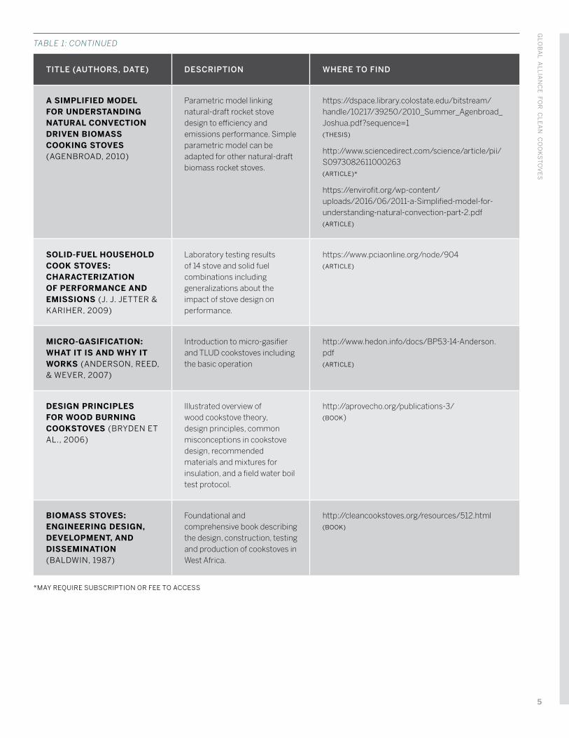
TITLE (AUTHORS, DATE) DESCRIPTION WHERE TO FIND
A SIMPLIFIED MODEL FOR UNDERSTANDING NATURAL CONVECTION DRIVEN BIOMASS COOKING STOVES (AGENBROAD, 2010)
Parametric model linking natural-draft rocket stove design to efficiency and emissions performance. Simple parametric model can be adapted for other natural-draft biomass rocket stoves.
https://dspace.library.colostate.edu/bitstream/handle/10217/39250/2010_Summer_Agenbroad_Joshua.pdf?sequence=1 (THESIS)
http://www.sciencedirect.com/science/article/pii/S0973082611000263 (ARTICLE)*
https://envirofit.org/wp-content/uploads/2016/06/2011-a-Simplified-model-for-understanding-natural-convection-part-2.pdf (ARTICLE)
SOLID-FUEL HOUSEHOLD COOK STOVES: CHARACTERIZATION OF PERFORMANCE AND EMISSIONS (J. J. JETTER & KARIHER, 2009)
Laboratory testing results of 14 stove and solid fuel combinations including generalizations about the impact of stove design on performance.
https://www.pciaonline.org/node/904 (ARTICLE)
MICRO-GASIFICATION: WHAT IT IS AND WHY IT WORKS (ANDERSON, REED, & WEVER, 2007)
Introduction to micro-gasifier and TLUD cookstoves including the basic operation
http://www.hedon.info/docs/BP53-14-Anderson.pdf (ARTICLE)
DESIGN PRINCIPLES FOR WOOD BURNING COOKSTOVES (BRYDEN ET AL., 2006)
Illustrated overview of wood cookstove theory, design principles, common misconceptions in cookstove design, recommended materials and mixtures for insulation, and a field water boil test protocol.
http://aprovecho.org/publications-3/ (BOOK)
BIOMASS STOVES: ENGINEERING DESIGN, DEVELOPMENT, AND DISSEMINATION (BALDWIN, 1987)
Foundational and comprehensive book describing the design, construction, testing and production of cookstoves in West Africa.
http://cleancookstoves.org/resources/512.html (BOOK)
*MAY REQUIRE SUBSCRIPTION OR FEE TO ACCESS
TABLE 1: CONTINUED
GLO
BA
L AL
LIA
NC
E FO
R C
LE
AN
CO
OK
ST
OV
ES
5
Below are examples of design requirements for cookstoves, each with a measurable target.
∙ Cooks 1 kg of rice in no more than one hour
∙ Weighs no more than 5 kg
∙ Achieves 30% thermal efficiency.
∙ Uses materials available within the country
∙ Additional cost of cookstove is recovered through fuel savings in less than one year
∙ Parts of the stove that are most likely to fail can be easily replaced
∙ Aesthetically pleasing to potential users
∙ Achieves a Biomass Stove Safety score of at least 88
DESIGN TEAM PROFILE:
TEAM JUMUIYA WAMU IN EAST AFRICA
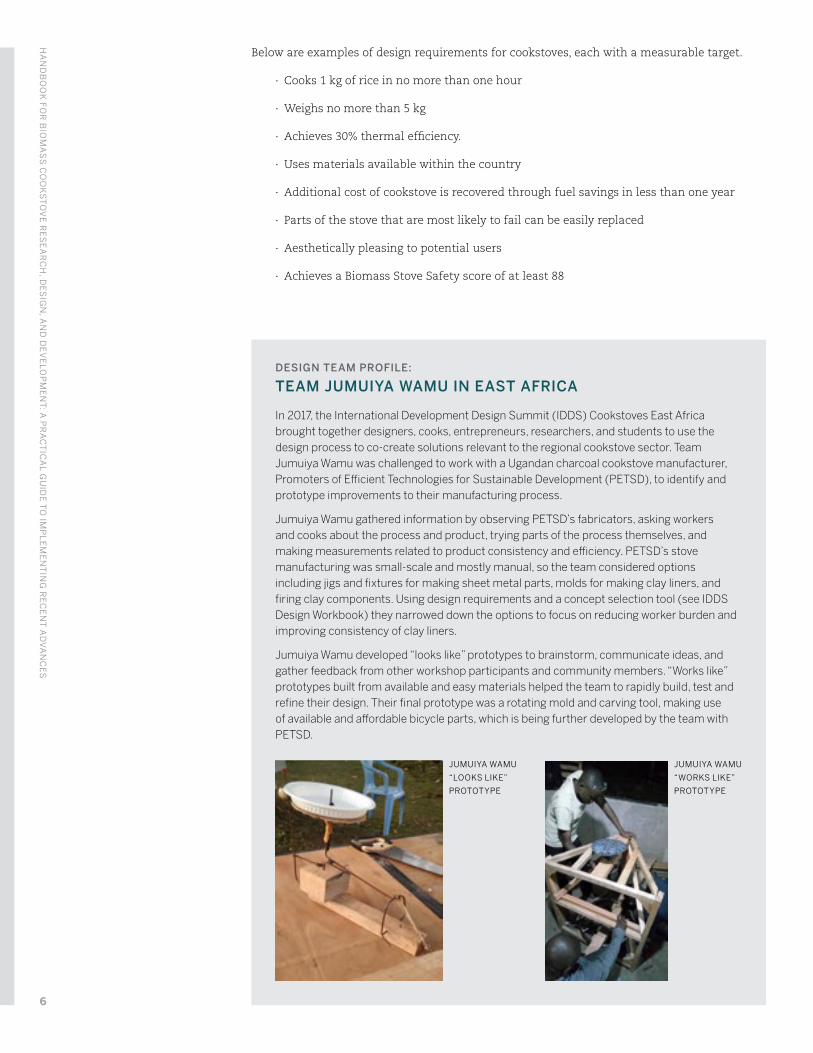
In 2017, the International Development Design Summit (IDDS) Cookstoves East Africa brought together designers, cooks, entrepreneurs, researchers, and students to use the design process to co-create solutions relevant to the regional cookstove sector. Team Jumuiya Wamu was challenged to work with a Ugandan charcoal cookstove manufacturer, Promoters of Efficient Technologies for Sustainable Development (PETSD), to identify and prototype improvements to their manufacturing process.
Jumuiya Wamu gathered information by observing PETSD’s fabricators, asking workers and cooks about the process and product, trying parts of the process themselves, and making measurements related to product consistency and efficiency. PETSD’s stove manufacturing was small-scale and mostly manual, so the team considered options including jigs and fixtures for making sheet metal parts, molds for making clay liners, and firing clay components. Using design requirements and a concept selection tool (see IDDS Design Workbook) they narrowed down the options to focus on reducing worker burden and improving consistency of clay liners.
Jumuiya Wamu developed “looks like” prototypes to brainstorm, communicate ideas, and gather feedback from other workshop participants and community members. “Works like” prototypes built from available and easy materials helped the team to rapidly build, test and refine their design. Their final prototype was a rotating mold and carving tool, making use of available and affordable bicycle parts, which is being further developed by the team with PETSD.
JUMUIYA WAMU
“LOOKS LIKE”
PROTOTYPE
JUMUIYA WAMU
“WORKS LIKE”
PROTOTYPE
HA
ND
BO
OK
FOR
BIO
MA
SS
CO
OK
ST
OV
E R
ES
EA
RC
H, D
ES
IGN
, AN
D D
EV
ELO
PM
EN
T: A
PR
AC
TIC
AL G
UID
E T
O IM
PL
EM
EN
TIN
G R
EC
EN
T A
DV
AN
CE
S
6
1.3 PERFORMANCE TESTING
It is difficult predict cookstove performance without measurements. Therefore, testing is an important tool that designers should use to develop their solution and to estimate potential environmental, health, social, and economic impacts.
Cookstove testing is usually done using standard methods,2 which include tests performed in the laboratory and the field. Laboratory testing is useful for gathering detailed measure-ments, including fuel efficiency and emissions, in a controlled environment. Field testing is used to understand how the product performs during use in a kitchen with real cooks. Updated laboratory and field testing standards currently being developed through the International Organization for Standardization (ISO) will help to make sure accurate, high-quality product testing is performed at centers around the world.3
During early stages of the design process, simple tests can be performed to compare proto-types. Aprovecho Research Center (ARC) provides a guide for performing a simplified water boil tests that designers can use to evaluate prototypes (Bryden et al., 2006). Designers are also encouraged to work with Regional Testing and Knowledge Centers (RTKCs), which are located
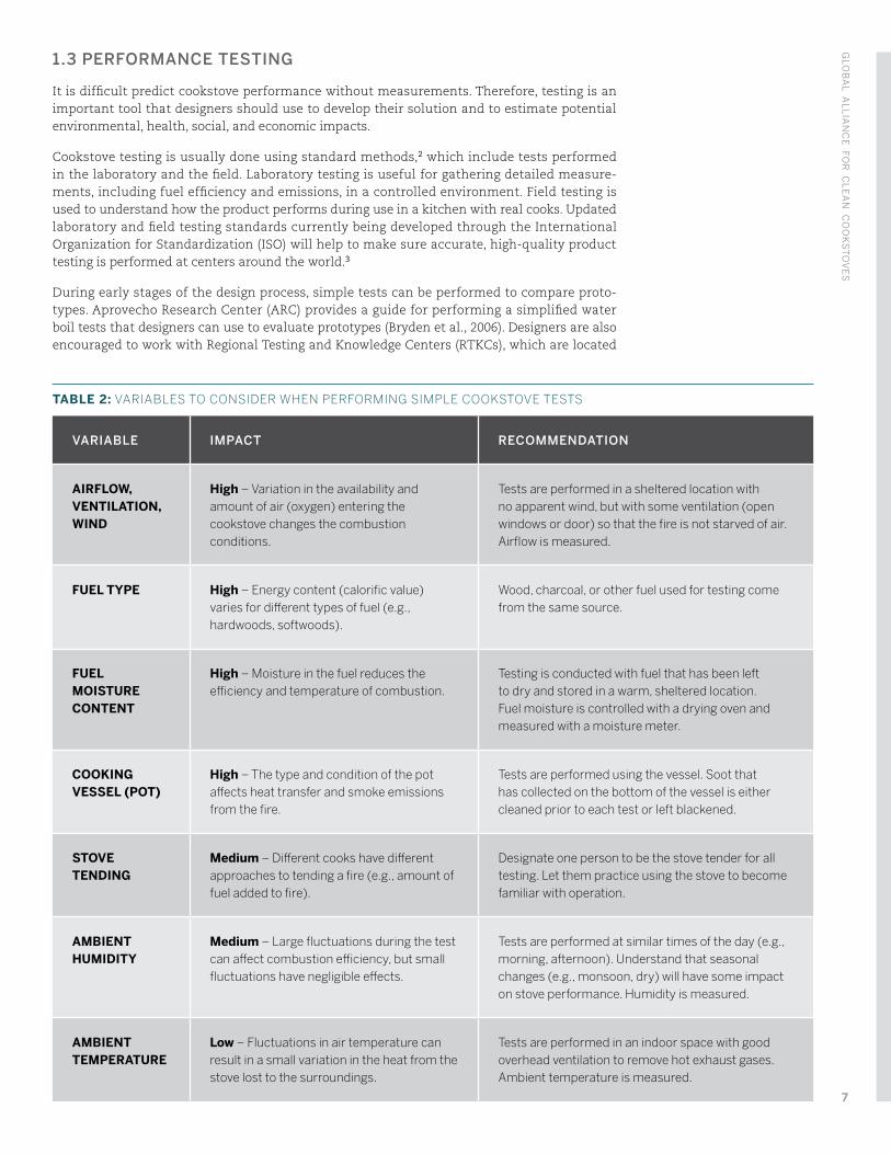
TABLE 2: VARIABLES TO CONSIDER WHEN PERFORMING SIMPLE COOKSTOVE TESTS
VARIABLE IMPACT RECOMMENDATION
AIRFLOW, VENTILATION, WIND
High – Variation in the availability and amount of air (oxygen) entering the cookstove changes the combustion conditions.
Tests are performed in a sheltered location with no apparent wind, but with some ventilation (open windows or door) so that the fire is not starved of air. Airflow is measured.
FUEL TYPE High – Energy content (calorific value) varies for different types of fuel (e.g., hardwoods, softwoods).
Wood, charcoal, or other fuel used for testing come from the same source.
FUEL MOISTURE CONTENT
High – Moisture in the fuel reduces the efficiency and temperature of combustion.
Testing is conducted with fuel that has been left to dry and stored in a warm, sheltered location. Fuel moisture is controlled with a drying oven and measured with a moisture meter.
COOKING VESSEL (POT)
High – The type and condition of the pot affects heat transfer and smoke emissions from the fire.
Tests are performed using the vessel. Soot that has collected on the bottom of the vessel is either cleaned prior to each test or left blackened.
STOVE TENDING
Medium – Different cooks have different approaches to tending a fire (e.g., amount of fuel added to fire).
Designate one person to be the stove tender for all testing. Let them practice using the stove to become familiar with operation.
AMBIENT HUMIDITY
Medium – Large fluctuations during the test can affect combustion efficiency, but small fluctuations have negligible effects.
Tests are performed at similar times of the day (e.g., morning, afternoon). Understand that seasonal changes (e.g., monsoon, dry) will have some impact on stove performance. Humidity is measured.
AMBIENT TEMPERATURE
Low – Fluctuations in air temperature can result in a small variation in the heat from the stove lost to the surroundings.
Tests are performed in an indoor space with good overhead ventilation to remove hot exhaust gases. Ambient temperature is measured.
GLO
BA
L AL
LIA
NC
E FO
R C
LE
AN
CO
OK
ST
OV
ES
7
worldwide and provide cookstove testing and design advising services.4 RTKCs can help at any stage of design, manufacturing, and introduction to the market. In some countries, products can be certified for being efficient or low emissions based on testing.
It is common for laboratory performance test results to be reported using the ISO International Workshop Agreement (IWA) Tier system.5 Tier ratings correspond to ranges of performance levels for efficiency, indoor and total emissions, and safety. Tier ratings provide a common language to help designers set goals for stove performance. For example, a designer might target Tier 2 thermal efficiency, Tier 3 CO and PM2.5 indoor emissions, and Tier 4 safety. A designer may also target Tier 3 thermal efficiency as a longer term goal. This handbook references the Tier system for cookstove performance.
Comparative testing requires that design variables that can affect the results are maintained as constant as possible. The key variables to consider are listed in Table 2 (page 7).
1.4 IMPORTANT COMBUSTION CONCEPTS
The cooking system: The cooking system includes the cookstove, fuel, cooking vessel (e.g., pot), user, and kitchen. All of these influence the impacts that a cookstove has on the user and environment. Testing in the laboratory focuses more on the cookstove than other parts of the system, while field testing incorporates all parts of the system.
Combustion and products of incomplete combustion (PICs): Combustion is the process of a fuel reacting with oxygen to produce heat and other products. Complete combustion occurs when the amount of oxygen and mixing of fuel and oxygen is sufficient to completely convert all of the fuel to heat, carbon dioxide (CO2), and water vapor (H2O) (Equation 1). Incomplete combustion occurs when the amount of oxygen and mixing is insufficient, resulting in partial conversion of the fuel and emission of products of incomplete combustion (PICs, e.g., carbon monoxide, particulate matter, methane, other hydrocarbons), many of which are associated with health and climate risks (Equation 2). The combustion zone is the high-temperature region containing burning fuel and gases in the flame. Fuel-rich combustion occurs when the amount of air is insufficient to combust all of the fuel in an area of the combustor. Fuel-lean combustion occurs when more air than needed for complete combustion is present. Solid-fuel cookstoves typically operate fuel-lean overall, but local fuel-rich regions are still present within the combustion zone.
fuel + O2 heat + CO2 + H2O
fuel + O2 heat + CO2 + H2O + PICs
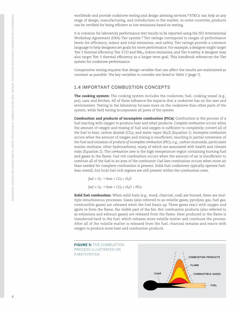
Solid fuel combustion: When solid fuels (e.g., wood, charcoal, coal) are burned, there are mul-tiple simultaneous processes. Gases (also referred to as volatile gases, pyrolysis gas, fuel gas, combustible gases) are released when the fuel heats up. These gases react with oxygen and ignite to form the flame, the visible part of the fire. Hot combustion products (also referred to as emissions and exhaust gases) are released from the flame. Heat produced in the flame is transferred back to the fuel, which releases more volatile matter and continues the process. After all of the volatile matter is released from the fuel, charcoal remains and reacts with oxygen to produce more heat and combustion products.
FIGURE 5: THE COMBUSTION PROCESS ILLUSTRATED ON A MATCHSTICK
CHAR
COMBUSTION PRODUCTS
FLAME
COMBUSTIBLE GASES
FUEL
HA
ND
BO
OK
FOR
BIO
MA
SS
CO
OK
ST
OV
E R
ES
EA
RC
H, D
ES
IGN
, AN
D D
EV
ELO
PM
EN
T: A
PR
AC
TIC
AL G
UID
E T
O IM
PL
EM
EN
TIN
G R
EC
EN
T A
DV
AN
CE
S
8
Efficiency: In general, efficiency is a comparison of the useful output of a system to the inputs. For cookstoves, the input is the fuel that produces heat energy through combustion, which is transferred to food or lost to the surroundings. The thermal efficiency is the percentage of heat released from the fuel that is transferred to water or food in the pot. For more information about efficiency measurements see J. Jetter et al., 2012.
Emissions: Emissions are the products released from a process (e.g., combustion, biodegrada-tion) including gases, vapors, and particles. For cookstoves, some emissions are of particular interest because of their effects on health and climate, including carbon dioxide (CO2), carbon monoxide (CO), fine particulate matter (PM2.5) and black carbon (BC).
Flow path: The route through the cookstove that gases flow, from air inlet, through the combus-tion zone (burning fuel, gases, and flame), and the stove exit along the pot.
Turndown and turndown ratio: Turndown is the ability to reduce a cookstove’s heat output without the fire going out, and while maintaining good performance. The turndown ratio is the ratio of the maximum firepower to the minimum firepower for a stove.
Thermal mass: Thermal mass is a property of a material that enables it to absorb and store heat. Materials with high thermal mass can absorb and store large amounts of heat, resulting in a relatively low rate of temperature increase when exposed to a hot environment. After heating up, high thermal mass materials slowly release stored heat.
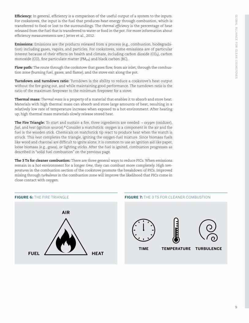
The Fire Triangle: To start and sustain a fire, three ingredients are needed: – oxygen (oxidizer), fuel, and heat (ignition source).6 Consider a matchstick: oxygen is a component in the air and the fuel is the wooden stick. Chemicals on matchstick tip react to produce heat when the match is struck. This heat completes the triangle, igniting the oxygen-fuel mixture. Since biomass fuels like wood and charcoal are difficult to ignite alone, it is common to use an ignition aid like paper, loose biomass (e.g., grass), or lighting sticks. After the fuel is ignited, combustion progresses as described in “solid fuel combustion” on the previous page.
The 3 Ts for cleaner combustion: There are three general ways to reduce PICs. When emissions remain in a hot environment for a longer time, they can combust more completely. High tem-peratures in the combustion section of the cookstove promote the breakdown of PICs. Improved mixing through turbulence in the combustion zone will improve the likelihood that PICs come in close contact with oxygen.
FIGURE 7: THE 3 TS FOR CLEANER COMBUSTION
TIME TEMPERATURE TURBULENCE
FIGURE 6: THE FIRE TRIANGLE
AIR
FUEL HEAT
GLO
BA
L AL
LIA
NC
E FO
R C
LE
AN
CO
OK
ST
OV
ES
9
1.5 TYPES OF BIOMASS STOVES
Batch-operated refers to stoves that are operated on a single load of fuel at a time.
Continuously fed stoves require fuel to be loaded throughout the cooking process.
Rocket (also known as side-fed) stoves are fueled with wood sticks or biomass residues that are continuously fed (see “Fuel” section below) through the side of the stove, typically resting on a grate so that ash and charcoal can settle below. Air enters by natural- or forced-draft (see “Air” section below) through the same opening as the fuel. (Examples: Grameen Greenway Smartstove, Envirofit G-3300, Ecozoom Zoom Stove)
Gasifier stoves are batch- or continuously fed using processed fuel (e.g., pellets, reduced size residues). Combustion occurs in two zones — the pyrolysis zone where fuel is heated to produce combustible gases, and the combustion zone where pyrolysis gases are mixed with air and combusted to produce heat. (Examples: Awamu Troika, Mimi Moto, Philips ACE 1)
Charcoal stoves are batch-operated and fueled with charcoal or carbonized biomass, which is produced through pyrolysis to remove volatile matter leaving mostly carbon. (Examples: Kenyan Ceramic Jiko, Envirofit CH-2200, Burn Jikokoa)
Forced-draft / fan stoves have air that is forced into the stove using a fan or blower to enhance turbulence and promote cleaner combustion (Example: BioLite HomeStove)
Descriptions of other cookstove types, including liquid, gas, electric, and solar stoves, can be found on the Alliance website.7
HA
ND
BO
OK
FOR
BIO
MA
SS
CO
OK
ST
OV
E R
ES
EA
RC
H, D
ES
IGN
, AN
D D
EV
ELO
PM
EN
T: A
PR
AC
TIC
AL G
UID
E T
O IM
PL
EM
EN
TIN
G R
EC
EN
T A
DV
AN
CE
S
10
2. RESEARCH & DESIGN SYNTHESIS
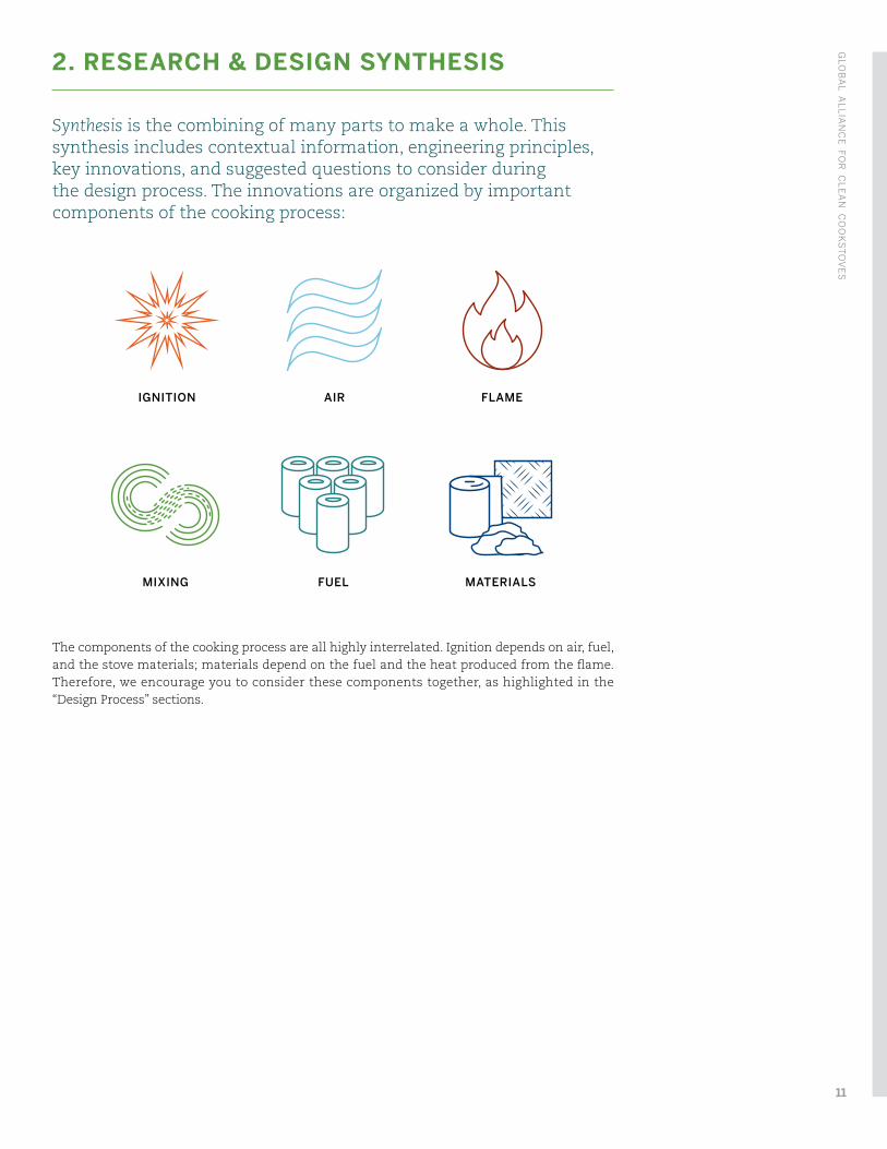
Synthesis is the combining of many parts to make a whole. This synthesis includes contextual information, engineering principles, key innovations, and suggested questions to consider during the design process. The innovations are organized by important components of the cooking process:
The components of the cooking process are all highly interrelated. Ignition depends on air, fuel, and the stove materials; materials depend on the fuel and the heat produced from the flame. Therefore, we encourage you to consider these components together, as highlighted in the “Design Process” sections.
IGNITION AIR FLAME
MIXING FUEL MATERIALS
GLO
BA
L AL
LIA
NC
E FO
R C
LE
AN
CO
OK
ST
OV
ES
11
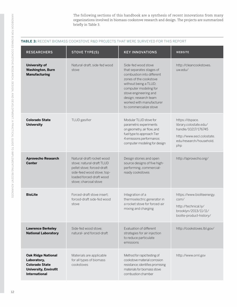
TABLE 3: RECENT BIOMASS COOKSTOVE R&D PROJECTS THAT WERE SURVEYED FOR THIS REPORT
RESEARCHERS STOVE TYPE(S) KEY INNOVATIONS WEBSITE
University of Washington, Burn Manufacturing
Natural-draft, side-fed wood stove
Side-fed wood stove that separates stages of combustion into different zones of the cookstove without being a TLUD; computer modeling for stove engineering and design; research team worked with manufacturer to commercialize stove
http://cleancookstoves.uw.edu/
Colorado State University
TLUD gasifier Modular TLUD stove for parametric experiments on geometry, air flow, and fuel type to approach Tier 4 emissions performance; computer modeling for design
https://dspace.library.colostate.edu/handle/10217/176745
http://www.eecl.colostate.edu/research/household.php
Aprovecho Research Center
Natural-draft rocket wood stove; natural-draft TLUD pellet stove; forced-draft side-feed wood stove; top-loaded forced-draft wood stove; charcoal stove
Design stories and open source designs of five high-performing, commercial-ready cookstoves
http://aprovecho.org/
BioLite Forced-draft stove insert; forced-draft side-fed wood stove
Integration of a thermoelectric generator in a rocket stove for forced-air mixing and charging
https://www.bioliteenergy.com/
http://technical.ly/brooklyn/2013/11/11/biolite-product-history/
Lawrence Berkeley National Laboratory
Side-fed wood stove; natural- and forced-draft
Evaluation of different strategies for air injection to reduce particulate emissions
http://cookstoves.lbl.gov/
Oak Ridge National Laboratory, Colorado State University, Envirofit International
Materials are applicable for all types of biomass cookstoves
Method for rapid testing of cookstove material corrosion resistance; identifies promising materials for biomass stove combustion chamber
http://www.ornl.gov
The following sections of this handbook are a synthesis of recent innovations from many organizations involved in biomass cookstove research and design. The projects are summarized briefly in Table 3.
HA
ND
BO
OK
FOR
BIO
MA
SS
CO
OK
ST
OV
E R
ES
EA
RC
H, D
ES
IGN
, AN
D D
EV
ELO
PM
EN
T: A
PR
AC
TIC
AL G
UID
E T
O IM
PL
EM
EN
TIN
G R
EC
EN
T A
DV
AN
CE
S
12
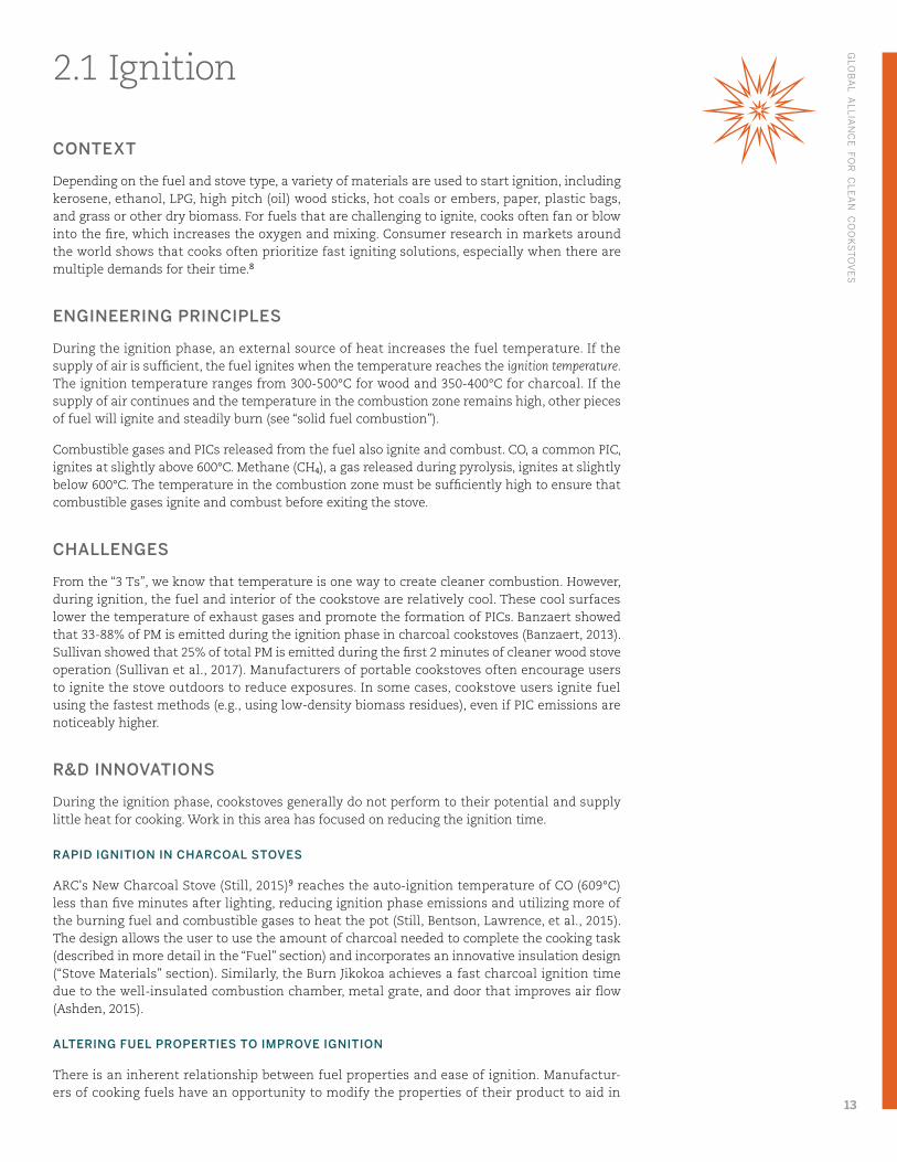
2.1 Ignition
CONTEXT
Depending on the fuel and stove type, a variety of materials are used to start ignition, including kerosene, ethanol, LPG, high pitch (oil) wood sticks, hot coals or embers, paper, plastic bags, and grass or other dry biomass. For fuels that are challenging to ignite, cooks often fan or blow into the fire, which increases the oxygen and mixing. Consumer research in markets around the world shows that cooks often prioritize fast igniting solutions, especially when there are multiple demands for their time.8
ENGINEERING PRINCIPLES
During the ignition phase, an external source of heat increases the fuel temperature. If the supply of air is sufficient, the fuel ignites when the temperature reaches the ignition temperature. The ignition temperature ranges from 300-500°C for wood and 350-400°C for charcoal. If the supply of air continues and the temperature in the combustion zone remains high, other pieces of fuel will ignite and steadily burn (see “solid fuel combustion”).
Combustible gases and PICs released from the fuel also ignite and combust. CO, a common PIC, ignites at slightly above 600°C. Methane (CH4), a gas released during pyrolysis, ignites at slightly below 600°C. The temperature in the combustion zone must be sufficiently high to ensure that combustible gases ignite and combust before exiting the stove.
CHALLENGES
From the “3 Ts”, we know that temperature is one way to create cleaner combustion. However, during ignition, the fuel and interior of the cookstove are relatively cool. These cool surfaces lower the temperature of exhaust gases and promote the formation of PICs. Banzaert showed that 33-88% of PM is emitted during the ignition phase in charcoal cookstoves (Banzaert, 2013). Sullivan showed that 25% of total PM is emitted during the first 2 minutes of cleaner wood stove operation (Sullivan et al., 2017). Manufacturers of portable cookstoves often encourage users to ignite the stove outdoors to reduce exposures. In some cases, cookstove users ignite fuel using the fastest methods (e.g., using low-density biomass residues), even if PIC emissions are noticeably higher.
R&D INNOVATIONS
During the ignition phase, cookstoves generally do not perform to their potential and supply little heat for cooking. Work in this area has focused on reducing the ignition time.
RAPID IGNITION IN CHARCOAL STOVES
ARC's New Charcoal Stove (Still, 2015)9 reaches the auto-ignition temperature of CO (609°C) less than five minutes after lighting, reducing ignition phase emissions and utilizing more of the burning fuel and combustible gases to heat the pot (Still, Bentson, Lawrence, et al., 2015). The design allows the user to use the amount of charcoal needed to complete the cooking task (described in more detail in the “Fuel” section) and incorporates an innovative insulation design (“Stove Materials” section). Similarly, the Burn Jikokoa achieves a fast charcoal ignition time due to the well-insulated combustion chamber, metal grate, and door that improves air flow (Ashden, 2015).
ALTERING FUEL PROPERTIES TO IMPROVE IGNITION
There is an inherent relationship between fuel properties and ease of ignition. Manufactur-ers of cooking fuels have an opportunity to modify the properties of their product to aid in
GLO
BA
L AL
LIA
NC
E FO
R C
LE
AN
CO
OK
ST
OV
ES
13
ignition. Some manufactured charcoal briquettes include small amounts of additives, like sodium nitrate and sawdust, to make lighting easier and ignition faster (Mauer, 2006), without significantly increasing the amount of emissions during ignition or steady combustion. When considering fuel additives, designers should understand all the effects through product testing and consulting material safety data sheets (MSDS).
Reducing fuel size (lower mass and larger fuel surface area) helps ignition by improving the rate of temperature increase, fuel interaction with oxygen, and reducing the time to reach steady combustion. However, in general, designers should also consider that burn rate is faster for smaller size fuels, especially for batch-operated cookstoves.
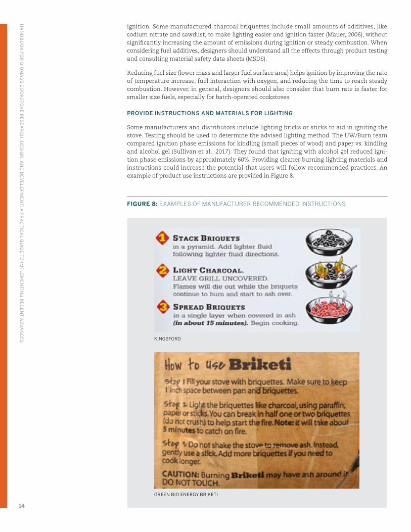
PROVIDE INSTRUCTIONS AND MATERIALS FOR LIGHTING
Some manufacturers and distributors include lighting bricks or sticks to aid in igniting the stove. Testing should be used to determine the advised lighting method. The UW/Burn team compared ignition phase emissions for kindling (small pieces of wood) and paper vs. kindling and alcohol gel (Sullivan et al., 2017). They found that igniting with alcohol gel reduced igni-tion phase emissions by approximately 60%. Providing cleaner burning lighting materials and instructions could increase the potential that users will follow recommended practices. An example of product use instructions are provided in Figure 8.
FIGURE 8: EXAMPLES OF MANUFACTURER RECOMMENDED INSTRUCTIONS
KINGSFORD
GREEN BIO ENERGY BRIKETI
HA
ND
BO
OK
FOR
BIO
MA
SS
CO
OK
ST
OV
E R
ES
EA
RC
H, D
ES
IGN
, AN
D D
EV
ELO
PM
EN
T: A
PR
AC
TIC
AL G
UID
E T
O IM
PL
EM
EN
TIN
G R
EC
EN
T A
DV
AN
CE
S
14
DESIGN PROCESS
Usability
∙ How do users currently light similar cookstoves? Indoors or outdoors?
∙ Have they improvised creative solutions that you could consider?
∙ Do they consider lighting to be a significant burden when using their cookstove?
∙ Do users respond positively during trials with your stove or fuel?
∙ Are instructions provided with your stove or fuel easy to understand?
Affordability
∙ Do features that improve ignition performance of your stove (e.g., improved insulation, added airflow) have a significant impact on manufacturing cost?
∙ Is faster and cleaner ignition a feature that the user will value and pay for?
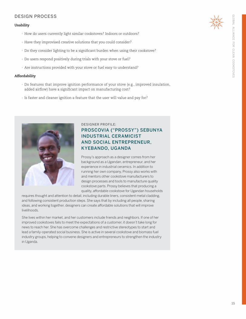
DESIGNER PROFILE:
PROSCOVIA (“PROSSY”) SEBUNYA INDUSTRIAL CERAMICIST AND SOCIAL ENTREPRENEUR, KYEBANDO, UGANDA
Prossy’s approach as a designer comes from her background as a Ugandan, entrepreneur, and her experience in industrial ceramics. In addition to running her own company, Prossy also works with and mentors other cookstove manufacturers to design processes and tools to manufacture quality cookstove parts. Prossy believes that producing a quality, affordable cookstove for Ugandan households
requires thought and attention to detail, including durable liners, consistent metal cladding, and following consistent production steps. She says that by including all people, sharing ideas, and working together, designers can create affordable solutions that will improve livelihoods.
She lives within her market, and her customers include friends and neighbors. If one of her improved cookstoves fails to meet the expectations of a customer, it doesn’t take long for news to reach her. She has overcome challenges and restrictive stereotypes to start and lead a family-operated social business. She is active in several cookstove and biomass fuel industry groups, helping to convene designers and entrepreneurs to strengthen the industry in Uganda.
GLO
BA
L AL
LIA
NC
E FO
R C
LE
AN
CO
OK
ST
OV
ES
15
2.2 Air
CONTEXT
Different types of cooking (e.g., simmering, frying, boiling) and levels of heat are needed for the wide variety of dishes around the world. Cooks control the heat of the fire by adjusting the fuel and/or air supply to the fire. Design features for easy air adjustment allow the cook to prepare a variety of dishes with one stove. However, changes in air supply can also affect the fuel burn rate, thermal efficiency, and completeness of combustion. Therefore, benefits to the user need to be balanced with performance.
ENGINEERING PRINCIPLES
From the Fire Triangle we know that air is essential for combustion. Air contains oxygen, which reacts with fuel to produce heat and combustible gases. The natural flow of air into a fire (“natural-draft”) is caused by density differences created by temperature differences. When combustion gases heat up, their density10 decreases to become lower than the density of cool air in the room, which causes the hot gases to lift up and exit the cookstove. New air enters the stove to fill the space. When the production of combustion gases increases, more air is drawn into the cookstove. In addition, the taller the riser section (vertical section above the burning fuel, Figure 9) the stronger the draft. To some degree, the change in air flow in response to firepower makes combustion a self-adjusting process.11
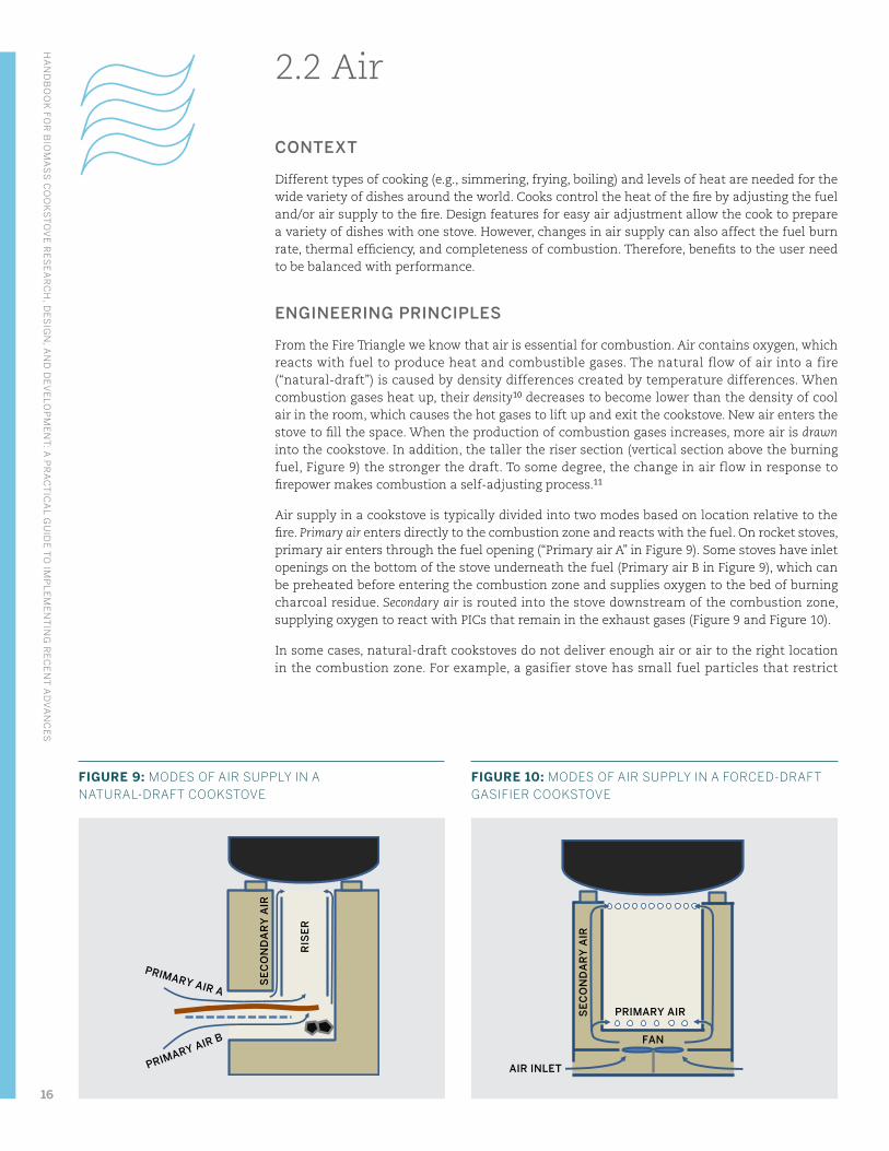
Air supply in a cookstove is typically divided into two modes based on location relative to the fire. Primary air enters directly to the combustion zone and reacts with the fuel. On rocket stoves, primary air enters through the fuel opening (“Primary air A” in Figure 9). Some stoves have inlet openings on the bottom of the stove underneath the fuel (Primary air B in Figure 9), which can be preheated before entering the combustion zone and supplies oxygen to the bed of burning charcoal residue. Secondary air is routed into the stove downstream of the combustion zone, supplying oxygen to react with PICs that remain in the exhaust gases (Figure 9 and Figure 10).
In some cases, natural-draft cookstoves do not deliver enough air or air to the right location in the combustion zone. For example, a gasifier stove has small fuel particles that restrict
RIS
ER
PRIMARY AIR A
PRIMARY AIR B
SE
CO
ND
AR
Y A
IR
SE
CO
ND
AR
Y A
IR
AIR INLET
PRIMARY AIR FAN
FIGURE 9: MODES OF AIR SUPPLY IN A NATURAL-DRAFT COOKSTOVE
FIGURE 10: MODES OF AIR SUPPLY IN A FORCED-DRAFT GASIFIER COOKSTOVE
HA
ND
BO
OK
FOR
BIO
MA
SS
CO
OK
ST
OV
E R
ES
EA
RC
H, D
ES
IGN
, AN
D D
EV
ELO
PM
EN
T: A
PR
AC
TIC
AL G
UID
E T
O IM
PL
EM
EN
TIN
G R
EC
EN
T A
DV
AN
CE
S
16
airflow. To address this challenge, forced-draft stoves use a fan or blower to control primary and secondary air, making the air flow more predictable and adjustable.
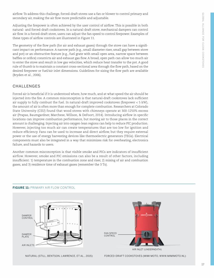
Adjusting the firepower is often achieved by the user control of airflow. This is possible in both natural- and forced-draft cookstoves. In a natural-draft stove, mechanical dampers can control air flow. In a forced-draft stove, users can adjust the fan speed to control firepower. Examples of these types of airflow controls are illustrated in Figure 11.
The geometry of the flow path (for air and exhaust gases) through the stove can have a signifi-cant impact on performance. A narrow path (e.g., small diameter riser, small gap between stove and pot) or an obstructive feature (e.g., fuel grate with small open area, narrow space between baffles or orifice) constricts air and exhaust gas flow. A broad, open path can allow too much air to enter the stove and result in low gas velocities, which reduce heat transfer to the pot. A good rule of thumb is to maintain a constant cross-sectional area through the flow path, based on the desired firepower or fuel/air inlet dimensions. Guidelines for sizing the flow path are available (Bryden et al., 2006).
CHALLENGES
Forced air is beneficial if it is understood where, how much, and at what speed the air should be injected into the fire. A common misconception is that natural-draft cookstoves lack sufficient air supply to fully combust the fuel. In natural-draft improved cookstoves (firepower < 5 kW), the amount of air is often more than enough for complete combustion. Researchers at Colorado State University (CSU) found that wood stoves with chimneys operate at 300-1250% excess air (Prapas, Baumgardner, Marchese, Willson, & DeFoort, 2014). Introducing airflow in specific locations can improve combustion performance, but moving air to those places in the correct amount is challenging. Injecting air into oxygen-lean regions can help to reduce PIC production. However, injecting too much air can create temperatures that are too low for ignition and reduce efficiency. Fans can be used to increase and direct airflow, but they require external power or the use of energy harvesting devices like thermoelectric generators (TEGs). Electrical components must also be integrated in a way that minimizes risk for overheating, electronics failure, and hazards to users.
Another common misconception is that visible smoke and PICs are indicators of insufficient airflow. However, smoke and PIC emissions can also be a result of other factors, including insufficient: 1) temperature in the combustion zone and riser, 2) mixing of air and combustion gases, and 3) residence time of exhaust gases (remember the 3 Ts).
NATURAL (STILL, BENTSON, LAWRENCE, ET AL., 2015) FORCED-DRAFT COOKSTOVES (MIMI MOTO, WWW.MIMIMOTO.NL)
DAMPER CONTROL
DAMPER PLATE
FAN SPEED CONTROL
AIR INLETS
AIR INLET (UNDERNEATH)
FIGURE 11: PRIMARY AIR FLOW CONTROL
GLO
BA
L AL
LIA
NC
E FO
R C
LE
AN
CO
OK
ST
OV
ES
17
R&D INNOVATIONS
The supply of air into the cookstove has a large effect on product performance and user experi-ence. Many researchers are optimizing air supply for different cookstove types.
MODULAR TEST STOVE AND PRIMARY AIR TO CONTROL FIREPOWER
Researchers at CSU explored different primary and secondary air arrangements for a top-lit, up draft (TLUD) gasifier stove (Tryner et al., 2016). In a TLUD, primary air provides oxygen for the production of pyrolysis gas. Hot fuel gas mixes with secondary air and ignites to form a flame. Instead of fabricating multiple stoves, CSU researchers designed a modular, adjustable stove for rapid testing of different stove configurations (e.g., primary and secondary air arrangements). In addition to saving time and cost, the modular stove allowed them to change only one feature while keeping all others the same. They found that the amount of primary air entering the fuel bed is proportional to the firepower of the cookstove. Understanding this relationship between air and firepower means that the designer can make sure that the stove can produce the levels of firepower that the users need.
BALANCING PRIMARY AND SECONDARY AIR
Most gasifier stoves, like the TLUD, rely on secondary air to combust gases produced in the pyrol-ysis zone. Too little secondary air leaves pyrolysis gas unburned. Too much secondary air cools the pyrolysis gas, resulting in an unstable flame and lower efficiency. The CSU team used their modular TLUD stove to investigate the ratio of primary and secondary air. They selected a range of reasonable values for primary air flow rate and secondary-to-primary air flow ratio and looked for the combination that led to the best performance. This type of experimentation is called parametric testing — adjusting design parameters to understand their impact on performance. For CSU’s modular TLUD stove, the lowest CO emissions were achieved with secondary-to-primary air ratios of 3:1 to 4:1 (mass basis) (Tryner et al., 2016). For every gram of primary air entering the pyrolysis zone, 3-4 grams of secondary air should be injected into the combustion zone.12
While the right amount of secondary air can help to improve emissions performance, this should be tested before incorporating into a final stove design. ARC tested secondary air addi-tion in their Side-Feed Forced-Draft stove and found no improvement in pollutant emissions and a reduction in heat transfer efficiency (Still, Bentson, Lawrence, et al., 2015).
AIR FLOW IN HIGH-PERFORMANCE CHARCOAL STOVES
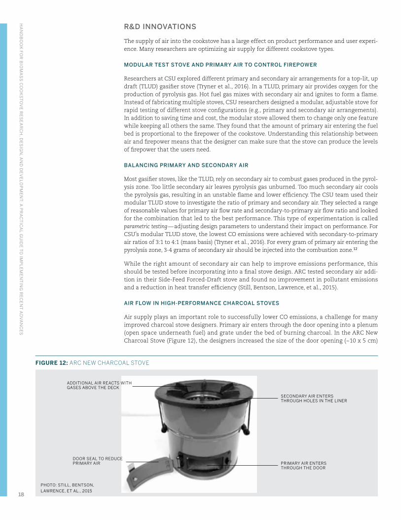
Air supply plays an important role to successfully lower CO emissions, a challenge for many improved charcoal stove designers. Primary air enters through the door opening into a plenum (open space underneath fuel) and grate under the bed of burning charcoal. In the ARC New Charcoal Stove (Figure 12), the designers increased the size of the door opening (~10 x 5 cm)
PHOTO: STILL, BENTSON, LAWRENCE, ET AL., 2015
ADDITIONAL AIR REACTS WITH GASES ABOVE THE DECK
SECONDARY AIR ENTERS THROUGH HOLES IN THE LINER
DOOR SEAL TO REDUCE PRIMARY AIR PRIMARY AIR ENTERS
THROUGH THE DOOR
FIGURE 12: ARC NEW CHARCOAL STOVE
HA
ND
BO
OK
FOR
BIO
MA
SS
CO
OK
ST
OV
E R
ES
EA
RC
H, D
ES
IGN
, AN
D D
EV
ELO
PM
EN
T: A
PR
AC
TIC
AL G
UID
E T
O IM
PL
EM
EN
TIN
G R
EC
EN
T A
DV
AN
CE
S
18
to allow more primary airflow. This reduced the ignition time and increased firepower and combustion temperature. A gap between the insulation and the metal combustion liner (shown in Figure 27) provides a channel for secondary air to heat up and flow by natural-draft into the region above the fuel bed (thirty 5mm holes). CO remaining in the exhaust gases meets the incoming secondary air and combusts. It is important that the secondary air is preheated so that the ignition temperature of CO can be reached. The ARC design is one of the first charcoal stoves to achieve Tier 4 ratings in thermal efficiency, and high- and low-power CO emissions.
DOOR DESIGN FOR PERFORMANCE AND USABILITY
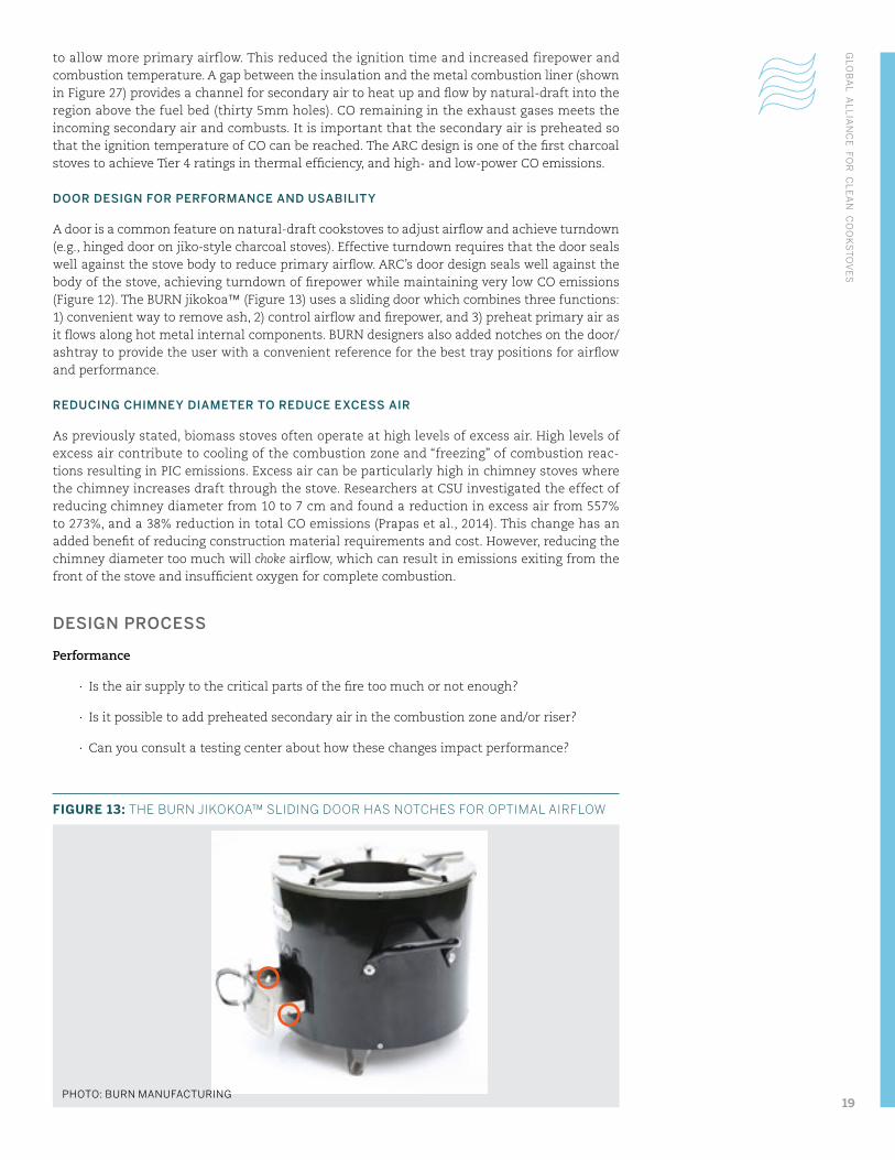
A door is a common feature on natural-draft cookstoves to adjust airflow and achieve turndown (e.g., hinged door on jiko-style charcoal stoves). Effective turndown requires that the door seals well against the stove body to reduce primary airflow. ARC’s door design seals well against the body of the stove, achieving turndown of firepower while maintaining very low CO emissions (Figure 12). The BURN jikokoa™ (Figure 13) uses a sliding door which combines three functions: 1) convenient way to remove ash, 2) control airflow and firepower, and 3) preheat primary air as it flows along hot metal internal components. BURN designers also added notches on the door/ashtray to provide the user with a convenient reference for the best tray positions for airflow and performance.
REDUCING CHIMNEY DIAMETER TO REDUCE EXCESS AIR
As previously stated, biomass stoves often operate at high levels of excess air. High levels of excess air contribute to cooling of the combustion zone and “freezing” of combustion reac-tions resulting in PIC emissions. Excess air can be particularly high in chimney stoves where the chimney increases draft through the stove. Researchers at CSU investigated the effect of reducing chimney diameter from 10 to 7 cm and found a reduction in excess air from 557% to 273%, and a 38% reduction in total CO emissions (Prapas et al., 2014). This change has an added benefit of reducing construction material requirements and cost. However, reducing the chimney diameter too much will choke airflow, which can result in emissions exiting from the front of the stove and insufficient oxygen for complete combustion.
DESIGN PROCESS
Performance
∙ Is the air supply to the critical parts of the fire too much or not enough?
∙ Is it possible to add preheated secondary air in the combustion zone and/or riser?
∙ Can you consult a testing center about how these changes impact performance?
PHOTO: BURN MANUFACTURING
FIGURE 13: THE BURN JIKOKOA™ SLIDING DOOR HAS NOTCHES FOR OPTIMAL AIRFLOW
GLO
BA
L AL
LIA
NC
E FO
R C
LE
AN
CO
OK
ST
OV
ES
19
∙ Does turndown of your stove impact the emissions and efficiency performance?
∙ Can the chimney diameter on your stove be reduced to limit excess air?
Manufacturing
∙ Can the design improve air supply without adding manufacturing challenges?
∙ What parts of the manufacturing process can be improved to maintain tight tolerances to control airflow? Can simple tools like patterns and jigs be used?
Durability
∙ Do changes in the air supply compromise the strength and durability of your stove (e.g., combustion liner is poorly supported due to addition of secondary air channel)?
∙ If integrating an electrical fan, control circuit, and/or battery into your stove, are these well-isolated from hot stove components?
Usability
∙ Do changes in the air supply change the user experience, negatively or positively?
∙ Do combustion residues like ash or charcoal block airflow paths?
∙ What firepower levels do your users need? If necessary, does your stove have a mechanism for turning down firepower (e.g., damper, door, fan)?
Safety
∙ Are electrical components in your stove isolated and protected?
Affordability
∙ Will design changes significantly affect the production cost of the stove?
∙ Does the design offer additional benefits to the user? Or meet the requirements of stakeholders that might support consumer financing?
HA
ND
BO
OK
FOR
BIO
MA
SS
CO
OK
ST
OV
E R
ES
EA
RC
H, D
ES
IGN
, AN
D D
EV
ELO
PM
EN
T: A
PR
AC
TIC
AL G
UID
E T
O IM
PL
EM
EN
TIN
G R
EC
EN
T A
DV
AN
CE
S
20
2.3 Fuel
CONTEXT
A range of fuels is used for cooking depending on availability, affordability, convenience, and suitability. The fuel is a good opportunity to improve the performance and user’s experience with the cooking system. Organizations are manufacturing fuels that are more environmentally sustainable, cleaner burning, and more convenient for the user. The fuel supply chain can also provide job opportunities. Common fuel types are presented in Appendix: Fuel types.
Some users are accustomed to purchasing goods in small quantities, especially consumables like cooking fuel. Though fuel purchased in bulk is often less expensive, consumers with little savings cannot afford large purchases. Opportunities for organizations to make bulk purchased fuels more accessible through financing or “pay-as-you-go” approaches can help to overcome this challenge and pass savings on to users.
ENGINEERING PRINCIPLES
Fuels can be divided into categories based on their physical state (solid, liquid, gas). The design goals for a cookstove depend greatly on the type and state of the associated fuel. For example, a cookstove designed for solid fuels should include a well-insulated combustion zone that allows combustible gases and PICs to burn. Solid fuels generally require more energy and take more time to ignite and reach operating temperature, and produce larger amounts of PM, but are more accessible and affordable in many markets. Liquid and gaseous fuels are generally faster and easier to ignite, emit few harmful pollutants, but can be less accessible. Refer to the description of solid fuel combustion in the “Important combustion concepts” section.
CHALLENGES
Fuels can be a challenging component in the cooking system because designers have little control over which fuel the user will choose. Performance of a given stove is generally different when operated with different types of fuel (e.g., hardwood vs. softwood, large vs. small, dry vs. moist). While a natural-draft wood stove may be designed to operate using 3-4 hardwood sticks at a time with <5% moisture content (MC) in the laboratory, a supply of that exact fuel might not be available in the community. Many cooks will improvise to find alternative solutions. Designing for fuel flexibility is challenging and requires a lot of testing and design iteration.
In response to the meal being prepared, household size, availability of fuel, availability of money, or time constraints, it is common for households to practice fuel and stove stacking — mixing use of different cookstoves and fuels. A household may have LPG, charcoal, and wood stoves and use a combination of all three. The more that the designer understands these preferences of and constraints on consumers, the better they can tailor their solution.
R&D INNOVATIONS
Researchers have focused not only on engineering cleaner fuels, but also designing cookstoves to accommodate fuel preferences of users and their cooking practices.
DESIGN FEATURES TO LIMIT FUEL INPUT
Many continuously fed cookstoves (e.g., rocket) have a relatively small fuel/air inlet, which limits the amount of fuel users can place in the stove. A small fuel/air inlet reduces heat loss to the surroundings. Limiting fuel in the combustion zone also reduces the production of com-bustible gases, which lowers the emissions. ARC’s Natural-Draft Sunken Pot Rocket Stove has relatively small fuel inlet, designed to burn four wood sticks at a time at a rate of about 0.5 kg per hour. In addition, a fence at the back of the fuel grate limits the amount of burning fuel to
GLO
BA
L AL
LIA
NC
E FO
R C
LE
AN
CO
OK
ST
OV
ES
21
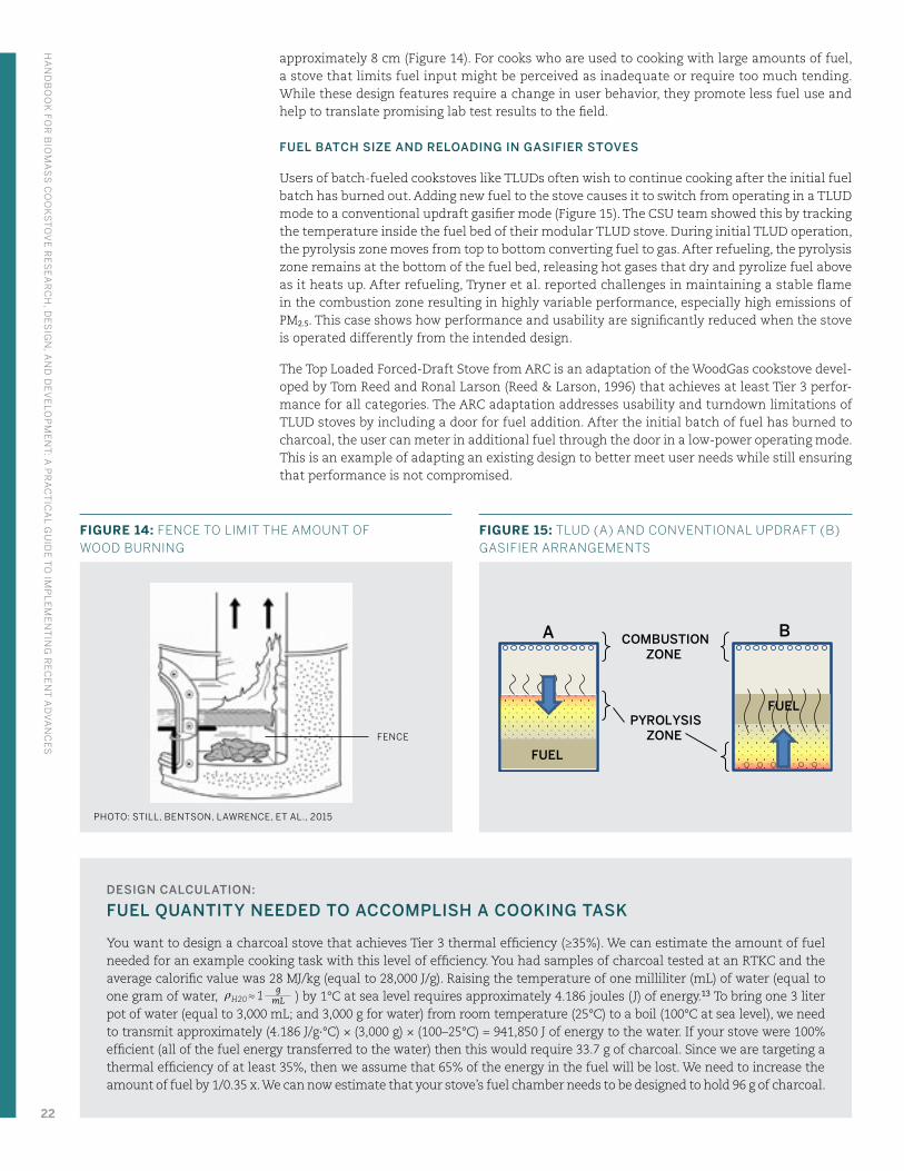
approximately 8 cm (Figure 14). For cooks who are used to cooking with large amounts of fuel, a stove that limits fuel input might be perceived as inadequate or require too much tending. While these design features require a change in user behavior, they promote less fuel use and help to translate promising lab test results to the field.
FUEL BATCH SIZE AND RELOADING IN GASIFIER STOVES
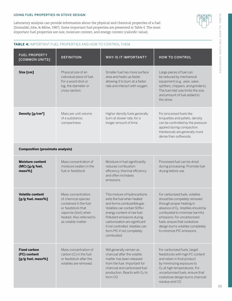
Users of batch-fueled cookstoves like TLUDs often wish to continue cooking after the initial fuel batch has burned out. Adding new fuel to the stove causes it to switch from operating in a TLUD mode to a conventional updraft gasifier mode (Figure 15). The CSU team showed this by tracking the temperature inside the fuel bed of their modular TLUD stove. During initial TLUD operation, the pyrolysis zone moves from top to bottom converting fuel to gas. After refueling, the pyrolysis zone remains at the bottom of the fuel bed, releasing hot gases that dry and pyrolize fuel above as it heats up. After refueling, Tryner et al. reported challenges in maintaining a stable flame in the combustion zone resulting in highly variable performance, especially high emissions of PM2.5. This case shows how performance and usability are significantly reduced when the stove is operated differently from the intended design.
The Top Loaded Forced-Draft Stove from ARC is an adaptation of the WoodGas cookstove devel-oped by Tom Reed and Ronal Larson (Reed & Larson, 1996) that achieves at least Tier 3 perfor-mance for all categories. The ARC adaptation addresses usability and turndown limitations of TLUD stoves by including a door for fuel addition. After the initial batch of fuel has burned to charcoal, the user can meter in additional fuel through the door in a low-power operating mode. This is an example of adapting an existing design to better meet user needs while still ensuring that performance is not compromised.
PHOTO: STILL, BENTSON, LAWRENCE, ET AL., 2015
FENCE
FIGURE 14: FENCE TO LIMIT THE AMOUNT OF WOOD BURNING
FUEL
PYROLYSISZONE
COMBUSTIONZONE
FUEL
A B
FIGURE 15: TLUD (A) AND CONVENTIONAL UPDRAFT (B) GASIFIER ARRANGEMENTS
DESIGN CALCULATION:
FUEL QUANTITY NEEDED TO ACCOMPLISH A COOKING TASK
You want to design a charcoal stove that achieves Tier 3 thermal efficiency (≥35%). We can estimate the amount of fuel needed for an example cooking task with this level of efficiency. You had samples of charcoal tested at an RTKC and the average calorific value was 28 MJ/kg (equal to 28,000 J/g). Raising the temperature of one milliliter (mL) of water (equal to one gram of water, ρH20 ≈ 1
gmL ) by 1°C at sea level requires approximately 4.186 joules ( J) of energy.13 To bring one 3 liter
pot of water (equal to 3,000 mL; and 3,000 g for water) from room temperature (25°C) to a boil (100°C at sea level), we need to transmit approximately (4.186 J/g∙°C) × (3,000 g) × (100–25°C) = 941,850 J of energy to the water. If your stove were 100% efficient (all of the fuel energy transferred to the water) then this would require 33.7 g of charcoal. Since we are targeting a thermal efficiency of at least 35%, then we assume that 65% of the energy in the fuel will be lost. We need to increase the amount of fuel by 1/0.35 x. We can now estimate that your stove’s fuel chamber needs to be designed to hold 96 g of charcoal.
HA
ND
BO
OK
FOR
BIO
MA
SS
CO
OK
ST
OV
E R
ES
EA
RC
H, D
ES
IGN
, AN
D D
EV
ELO
PM
EN
T: A
PR
AC
TIC
AL G
UID
E T
O IM
PL
EM
EN
TIN
G R
EC
EN
T A
DV
AN
CE
S
22
USING FUEL PROPERTIES IN STOVE DESIGN
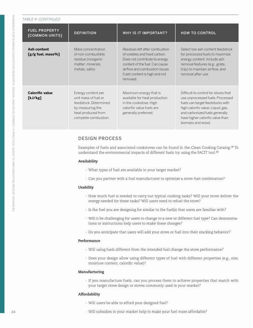
Laboratory analysis can provide information about the physical and chemical properties of a fuel (Domalski, Jobe, & Milne, 1987). Some important fuel properties are presented in Table 4. The most important fuel properties are size, moisture content, and energy content (calorific value).
TABLE 4: IMPORTANT FUEL PROPERTIES AND HOW TO CONTROL THEM
FUEL PROPERTY [COMMON UNITS]
DEFINITION WHY IS IT IMPORTANT? HOW TO CONTROL
Size [cm] Physical size of an individual piece of fuel. For a wood stick or log, the diameter or cross-section.
Smaller fuel has more surface area and heats up faster, allowing it to burn at a faster rate and interact with oxygen.
Large pieces of fuel can be reduced by mechanical equipment (e.g., axes, saws, splitters, chippers, and grinders). The fuel inlet size limits the size and amount of fuel added to the stove.
Density [g/cm3] Mass per unit volume of a substance; compactness
Higher density fuels generally burn at slower rate, for a longer amount of time
For processed fuels like briquettes and pellets, density can be controlled by the pressure applied during compaction. Hardwoods are generally more dense than softwoods.
Composition (proximate analysis)
Moisture content (MC) [g/g fuel, mass%]
Mass concentration of moisture (water) in the fuel or feedstock
Moisture in fuel significantly reduces combustion efficiency, thermal efficiency and often increases emissions
Processed fuel can be dried during processing. Promote fuel drying before use.
Volatile content [g/g fuel, mass%]
Mass concentration of chemical species contained in the fuel or feedstock that vaporize (boil) when heated. Also referred to as volatile matter
This mixture of hydrocarbons exits the fuel when heated and forms combustible gas. Volatiles can contain 50%+ energy content of raw fuel. Pollutant emissions during carbonization are significant if not controlled. Volatiles can form PIC if not completely combusted.
For carbonized fuels, volatiles should be completely removed through proper heating in absence of O2. Volatiles should be combusted to minimize harmful emissions. For uncarbonized fuels, ensure that cookstove design burns volatiles completely to minimize PIC emissions.
Fixed carbon (FC) content [g/g fuel, mass%]
Mass concentration of carbon (C) in the fuel or feedstock after the volatiles are removed.
Will generally remain as charcoal after the volatile matter has been released from the fuel. Important for charcoal and carbonized fuel production. Reacts with O2 to form CO.
For carbonized fuels, target feedstocks with high FC content and retain in final product by minimizing exposure to O2 at high temperatures. For uncarbonized fuels, ensure that cookstove design burns charcoal residue and CO.
GLO
BA
L AL
LIA
NC
E FO
R C
LE
AN
CO
OK
ST
OV
ES
23
FUEL PROPERTY [COMMON UNITS]
DEFINITION WHY IS IT IMPORTANT? HOW TO CONTROL
Ash content [g/g fuel, mass%]
Mass concentration of non-combustible residue (inorganic matter: minerals, metals, salts)
Residues left after combustion of volatiles and fixed carbon. Does not contribute to energy content of the fuel. Can cause airflow and combustion issues if ash content is high and not removed.
Select low ash content feedstock for processed fuels to maximize energy content. Include ash removal features (e.g., grate, tray) to maintain airflow, and removal after use.
Calorific value [kJ/kg]
Energy content per unit mass of fuel or feedstock. Determined by measuring the heat produced from complete combustion.
Maximum energy that is available for heat production in the cookstove. High calorific value fuels are generally preferred.
Difficult to control for stoves that use unprocessed fuels. Processed fuels can target feedstocks with high calorific value. Liquid, gas, and carbonized fuels generally have higher calorific value than biomass and wood.
DESIGN PROCESS
Examples of fuels and associated cookstoves can be found in the Clean Cooking Catalog.14 To understand the environmental impacts of different fuels try using the FACIT tool.15
Availability
∙ What types of fuel are available in your target market?
∙ Can you partner with a fuel manufacturer to optimize a stove-fuel combination?
Usability
∙ How much fuel is needed to carry out typical cooking tasks? Will your stove deliver the energy needed for these tasks? Will users need to refuel the stove?
∙ Is the fuel you are designing for similar to the fuel(s) that users are familiar with?
∙ Will it be challenging for users to change to a new or different fuel type? Can demonstra-tions or instructions help users to make these changes?
∙ Do you anticipate that users will add your stove or fuel into their stacking behavior?
Performance
∙ Will using fuels different from the intended fuel change the stove performance?
∙ Does your design allow using different types of fuel with different properties (e.g., size, moisture content, calorific value)?
Manufacturing
∙ If you manufacture fuels, can you process them to achieve properties that match with your target stove design or stoves commonly used in your market?
Affordability
∙ Will users be able to afford your designed fuel?
∙ Will subsidies in your market help to make your fuel more affordable?
TABLE 4: CONTINUED
HA
ND
BO
OK
FOR
BIO
MA
SS
CO
OK
ST
OV
E R
ES
EA
RC
H, D
ES
IGN
, AN
D D
EV
ELO
PM
EN
T: A
PR
AC
TIC
AL G
UID
E T
O IM
PL
EM
EN
TIN
G R
EC
EN
T A
DV
AN
CE
S
24
2.4 Flame
CONTEXT
The cook uses the presence of flame to confirm that a stove is operating and estimates the heat output by the size of the flame. Adjusting the air and fuel cause the flame to change size, shape, color, and sound. Cooks may also use light from the flame to prepare food or do other tasks. Experienced cooks are meticulous about responding to changes in the flame with adjustments to their stove. Though, when busy with other duties, the cook may set a large fire that continues to burn until they can return to cooking.
ENGINEERING PRINCIPLES
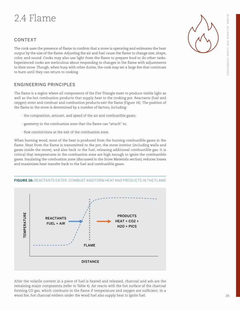
The flame is a region where all components of the Fire Triangle meet to produce visible light as well as the hot combustion products that supply heat to the cooking pot. Reactants (fuel and oxygen) enter and combust and combustion products exit the flame (Figure 16). The position of the flame in the stove is determined by a number of factors, including:
∙ the composition, amount, and speed of the air and combustible gases;
∙ geometry in the combustion zone that the flame can “attach” to;
∙ flow constrictions at the exit of the combustion zone.
When burning wood, most of the heat is produced from the burning combustible gases in the flame. Heat from the flame is transmitted to the pot, the stove interior (including walls and gases inside the stove), and also back to the fuel, releasing additional combustible gas. It is critical that temperatures in the combustion zone are high enough to ignite the combustible gases. Insulating the combustion zone (discussed in the Stove Materials section) reduces losses and maximizes heat transfer back to the fuel and combustible gases.
FIGURE 16: REACTANTS ENTER, COMBUST AND FORM HEAT AND PRODUCTS IN THE FLAME
After the volatile content in a piece of fuel is heated and released, charcoal and ash are the remaining major components (refer to Table 4). Air reacts with the hot surface of the charcoal forming CO gas, which combusts in the flame if temperature and oxygen are sufficient. In a wood fire, hot charcoal embers under the wood fuel also supply heat to ignite fuel.
REACTANTS
FUEL + AIR
PRODUCTS HEAT + CO2 +
H2O + PICS
FLAME
TE
MP
ER
AT
UR
E
DISTANCE
GLO
BA
L AL
LIA
NC
E FO
R C
LE
AN
CO
OK
ST
OV
ES
25
During charcoal-making, the volatile content that would produce flame is driven out of the feedstock. Thus, for charcoal and other carbonized fuels, a visible flame may or may not be present during combustion. Combustion and partial combustion reactions at, and in pores near the surface of the charcoal produce heat, CO, and CO2. If temperature and oxygen are sufficient, CO will combust, and form CO2 and a blue flame above the charcoal bed.
The color of a flame is determined by temperature and the chemical species combusting. For a pure, simple fuel like methane (CH4) combusting in air or oxygen, the color of the flame depends on temperature — from red at low temperature to blue at high temperature. For fuels made up of complex mixtures of chemicals, like wood, colors in the flame are more closely linked to the chemical species and particles combusting in those regions. Light gases like hydrogen (H2), CO and CH4 produce a blue flame, while longer hydrocarbons and soot particles produce a yellow flame. Insufficient air supply causes formation of PICs, which will alter the color of the flame (e.g., yellow light from soot particles).
The stability of the flame refers to the fluctuations of position and shape (e.g., long, short, wide, narrow). While flames are normally dynamic and rapidly changing, there are cases when the flame shifts position in the combustor, oscillates (regularly alternating in position or size), or in extreme cases, blows out completely. A stable flame remains relatively stationary in the combustion zone. Instability can be caused by changes in the flow rate of reactants (e.g., higher or lower flow of air and combustible gases), composition of the reactants, fuel-rich and –lean conditions, and restrictions on the exiting flow of the products. Unstable flames can cause complete loss of the flame, release of unburned gases and particles into the environment, and exposing components in the stove to temperatures higher than intended.
CHALLENGES
The presence of a flame does indicate that the Fire Triangle is complete. However, many factors contribute to a flame’s appearance and behavior, so it is difficult to make definitive conclusions about the flame. Measuring flames characteristics is also a challenging and active area of research. For the designer, focus on achieving a stable flame as soon as possible after ignition and maintaining that throughout the stove’s operation. Rapid changes in the composition and amount of combustible gas and air cause unstable flames. For example, inserting a fresh piece of “cold” wood in the fire temporarily absorbs a large amount of heat and releases large quantities of combustible gases.
For any combustion appliance, the safety of the user should be a design priority. When a flame is lost, there is an uncontrolled release of unburned gases into the kitchen that poses a serious health and safety risk to the people exposed. Contact with hot exterior surfaces, exposure to open flames, and tipping of stoves and pots of hot food are particular issues to mitigate through the design. Designers should also consider the safety of children as they may be near the stove, can be less cautious with hot objects, and are more vulnerable to injury.
R&D INNOVATIONS
Recent research on cookstove combustion includes fundamental research on chemistry, heat transfer and flow in the combustion zone, as well as applied research to ensure a stable flame and conversion of PICs in the flame. While there is still a lot to understand, there are useful learnings that can be put into practice.
STOVE GEOMETRY TO OPTIMIZE THE FLAME
Several research projects have shown that complete combustion and PIC reduction can be achieved through stove geometry. CSU researchers saw reduced PM emissions in their TLUD stove when the flame did not come into contact with pot (Tryner & Marchese, 2016). The cool surface of the pot rapidly cools the flame and stops combustion of PICs. Similarly, the UW/BURN researchers found that the height of the riser section can be optimized to give combustible gases enough time to completely combust (Means, 2016). However, increasing the riser height also increases the stove cost and the surface area for heat to be lost, so this parameter should be balanced. The internal stove geometry should be optimized for:
HA
ND
BO
OK
FOR
BIO
MA
SS
CO
OK
ST
OV
E R
ES
EA
RC
H, D
ES
IGN
, AN
D D
EV
ELO
PM
EN
T: A
PR
AC
TIC
AL G
UID
E T
O IM
PL
EM
EN
TIN
G R
EC
EN
T A
DV
AN
CE
S
26
∙ Flame position close to but not in contact with the pot
∙ Time for combustible gases to completely combust
∙ Primary air supply through natural-draft (chimney effect)
∙ Radiation heat transfer from the flame to the pot
∙ Overall cost of the cookstove
Balancing these interconnected parameters is challenging and requires designers to test proto-types, measure and observe changes in performance, and iterate.
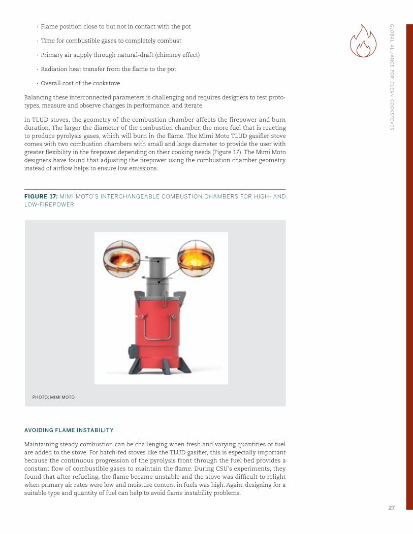
In TLUD stoves, the geometry of the combustion chamber affects the firepower and burn duration. The larger the diameter of the combustion chamber, the more fuel that is reacting to produce pyrolysis gases, which will burn in the flame. The Mimi Moto TLUD gasifier stove comes with two combustion chambers with small and large diameter to provide the user with greater flexibility in the firepower depending on their cooking needs (Figure 17). The Mimi Moto designers have found that adjusting the firepower using the combustion chamber geometry instead of airflow helps to ensure low emissions.
FIGURE 17: MIMI MOTO’S INTERCHANGEABLE COMBUSTION CHAMBERS FOR HIGH- AND LOW-FIREPOWER
AVOIDING FLAME INSTABILITY
Maintaining steady combustion can be challenging when fresh and varying quantities of fuel are added to the stove. For batch-fed stoves like the TLUD gasifier, this is especially important because the continuous progression of the pyrolysis front through the fuel bed provides a constant flow of combustible gases to maintain the flame. During CSU’s experiments, they found that after refueling, the flame became unstable and the stove was difficult to relight when primary air rates were low and moisture content in fuels was high. Again, designing for a suitable type and quantity of fuel can help to avoid flame instability problems.
PHOTO: MIMI MOTO
GLO
BA
L AL
LIA
NC
E FO
R C
LE
AN
CO
OK
ST
OV
ES
27
STAGED COMBUSTION
Researchers at the University of Washington (UW) and Burn Design Lab are using rigorous laboratory experimentation and testing (Sullivan et al., 2017), computer simulation (Pundle, Sullivan, Allawatt, Posner, & Kramlich, 2015), and field testing to design high-performance natural-draft, side-fed wood stoves.16 In addition to developing new design tools, their exper-imental and simulation work uncovered new stove design ideas for approaching Tier 4 level performance for emissions and efficiency. One concept uses staged combustion, similar to a batch-loaded gasifier stove where the fuel is pyrolyzed in the lower section of the stove and the rising pyrolysis gases are combusted in the upper section. This is different than typical side-fed cookstoves in which solid fuel pyrolysis and combustion occur simultaneously within the combustion zone. Additionally, most side-fed cookstoves have far more air entering the stove than is needed for complete combustion (2-6x excess air) (Sullivan, 2016). The UW side-fed design separates the flame into two sections by using a baffle in the riser and separate primary and secondary air streams (Posner, 2015). A door at the fuel inlet limits primary air supply to promote partial combustion and production of combustible gases. Secondary air is added low in the riser section to enable combustion of the gases produced in the primary zone.
DESIGN PROCESS
Usability
∙ Is the flame visible during stove operation? Or is there another indicator to the user that the stove is hot?
∙ How do users prefer to tend the fire? Lots of fuel producing large fires, or small fires to conserve fuel?
∙ What would cause instability or a loss of flame in your stove? How easily can the flame be recovered if lost?
Performance
∙ Is there visible soot (black particles) emitted from the flame?
∙ Does the flame come near the surface of the pot during stove operation?
∙ Does adding fresh fuel to the stove cause the flame to become unstable?
∙ Can a feature be added in the internal stove geometry that the flame can attach to while also sustaining high temperatures?
∙ Can a staged combustion approach be used in your stove?
Manufacturing
∙ How can your manufacturing process be updated to maintain tight tolerances needed for consistent geometric features?
Durability
∙ Does the flame touch components that are not meant to be exposed to high tempera-tures? Can another more durable material be used for those components?
Safety
∙ Is the flame confined within the combustion zone during normal operation? Are there cases where the flame could extend outside of the stove?
HA
ND
BO
OK
FOR
BIO
MA
SS
CO
OK
ST
OV
E R
ES
EA
RC
H, D
ES
IGN
, AN
D D
EV
ELO
PM
EN
T: A
PR
AC
TIC
AL G
UID
E T
O IM
PL
EM
EN
TIN
G R
EC
EN
T A
DV
AN
CE
S
28
2.5 Mixing
CONTEXT
Designers can produce a cleaner flame by creating an environment for fuel, air, and heat to swirl together in a chaotic and dynamic way (turbulence from the 3Ts). Since the interaction of air, fuel, and heat is difficult to observe and measure, it can be difficult to understand how to improve a design to promote mixing and turbulence. Conditions in the combustion zone are largely invisible to the user, and should be of little concern if the stove is running as designed.
ENGINEERING PRINCIPLES
There are two types of fluid flow (e.g., water, air, exhaust gases). Laminar flow is smooth, uniform, and predictable; like a river flowing over a dam. Turbulent flow, on the other hand, is chaotic and seemingly random; like a river rushing through a narrow, winding canyon. We can use the Reynolds number, a simple mathematical expression, to predict whether flow through a geometry will be laminar or turbulent:
Re = ρVDμ
where ρ is the fluid density (kg/m3), V is the velocity of the flow (m/s), D is the diameter of the geometry (e.g., pipe diameter, channel width) (m), and μ is the viscosity of the fluid17 (kg/m∙s).
Low Reynolds number flows are laminar and high Reynolds number flows are turbulent. For geometries like cookstoves, flow is laminar at Re < 2000, and fully turbulent at Re > 4000. Designers should aim for a high Reynolds number flow (turbulent) in the cookstove. Turbulence promotes air (O2) and fuel to interact with each other and create tiny fire triangles where combustible gases and PICs can combust.
According to the Reynolds number equation, the designer can increase the fluid velocity, pipe diameter, or fluid density, or decrease the fluid viscosity to shift from laminar to turbulent flow. Fluid density and viscosity are nearly impossible to control in real life. Diameter and velocity, which can be controlled, are related to each other by an expression for the volume flow rate of the fluid:
Q = V × A
where A is the cross-sectional area of the pipe:
A =π × D2
4
Therefore, if the volume flow rate is constant and the diameter is halved, the velocity increases by four times. Decreasing the inside dimension is a way to increase the Reynolds number. However, diameters that are too small restrict the flow of gases in the stove.
CHALLENGES
Observing the air and exhaust gas flow through a cookstove is challenging and requires sophis-ticated tools that are often expensive and difficult to use. Simple experiments and testing can help designers understand how changes, for example in combustion zone geometry, can affect emissions and efficiency performance. While complex models can be difficult to use directly, researchers have used these tools to evaluate the effectiveness of different design features, and their results can be used by every designer.
Many designers have been investigating the benefits of using forced-draft to improve mixing. In most cases, an electric fan built into the stove injects air into the fire through holes in the stove liner. The injection holes can direct controlled amounts of air into specific regions of the fire that might be oxygen deprived. Powering the fan is a key challenge, especially when a grid connection may not be available. Adding a battery and solar panel significantly increases the cost of the stove.
GLO
BA
L AL
LIA
NC
E FO
R C
LE
AN
CO
OK
ST
OV
ES
29
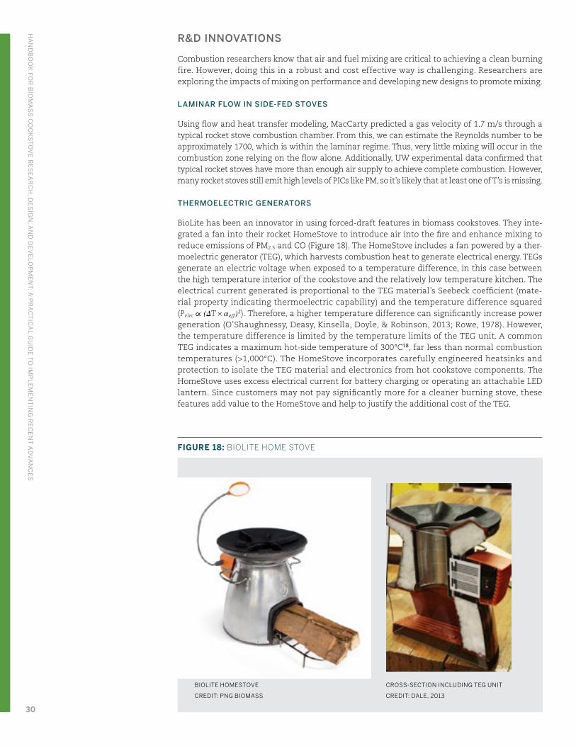
R&D INNOVATIONS
Combustion researchers know that air and fuel mixing are critical to achieving a clean burning fire. However, doing this in a robust and cost effective way is challenging. Researchers are exploring the impacts of mixing on performance and developing new designs to promote mixing.
LAMINAR FLOW IN SIDE-FED STOVES
Using flow and heat transfer modeling, MacCarty predicted a gas velocity of 1.7 m/s through a typical rocket stove combustion chamber. From this, we can estimate the Reynolds number to be approximately 1700, which is within the laminar regime. Thus, very little mixing will occur in the combustion zone relying on the flow alone. Additionally, UW experimental data confirmed that typical rocket stoves have more than enough air supply to achieve complete combustion. However, many rocket stoves still emit high levels of PICs like PM, so it’s likely that at least one of T’s is missing.
THERMOELECTRIC GENERATORS
BioLite has been an innovator in using forced-draft features in biomass cookstoves. They inte-grated a fan into their rocket HomeStove to introduce air into the fire and enhance mixing to reduce emissions of PM2.5 and CO (Figure 18). The HomeStove includes a fan powered by a ther-moelectric generator (TEG), which harvests combustion heat to generate electrical energy. TEGs generate an electric voltage when exposed to a temperature difference, in this case between the high temperature interior of the cookstove and the relatively low temperature kitchen. The electrical current generated is proportional to the TEG material’s Seebeck coefficient (mate-rial property indicating thermoelectric capability) and the temperature difference squared (Pelec ∝ (ΔT × αeff)2). Therefore, a higher temperature difference can significantly increase power generation (O’Shaughnessy, Deasy, Kinsella, Doyle, & Robinson, 2013; Rowe, 1978). However, the temperature difference is limited by the temperature limits of the TEG unit. A common TEG indicates a maximum hot-side temperature of 300°C18, far less than normal combustion temperatures (>1,000°C). The HomeStove incorporates carefully engineered heatsinks and protection to isolate the TEG material and electronics from hot cookstove components. The HomeStove uses excess electrical current for battery charging or operating an attachable LED lantern. Since customers may not pay significantly more for a cleaner burning stove, these features add value to the HomeStove and help to justify the additional cost of the TEG.
FIGURE 18: BIOLITE HOME STOVE
CROSS-SECTION INCLUDING TEG UNIT
CREDIT: DALE, 2013
BIOLITE HOMESTOVE
CREDIT: PNG BIOMASS
HA
ND
BO
OK
FOR
BIO
MA
SS
CO
OK
ST
OV
E R
ES
EA
RC
H, D
ES
IGN
, AN
D D
EV
ELO
PM
EN
T: A
PR
AC
TIC
AL G
UID
E T
O IM
PL
EM
EN
TIN
G R
EC
EN
T A
DV
AN
CE
S
30
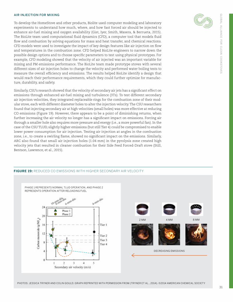
AIR INJECTION FOR MIXING
To develop the HomeStove and other products, Biolite used computer modeling and laboratory experiments to understand how much, where, and how fast forced air should be injected to enhance air-fuel mixing and oxygen availability (Gist, Iyer, Smith, Masera, & Berrueta, 2015). The BioLite team used computational fluid dynamics (CFD), a computer tool that models fluid flow and combustion by solving equations for mass and heat transfer, and chemical reactions. CFD models were used to investigate the impact of key design features like air injection on flow and temperatures in the combustion zone. CFD helped BioLite engineers to narrow down the possible design options and to choose specific parameters to test using physical prototypes. For example, CFD modeling showed that the velocity of air injected was an important variable for mixing and PM emissions performance. The BioLite team made prototype stoves with several different sizes of air injection holes to change the velocity and performed water boiling tests to measure the overall efficiency and emissions. The results helped BioLite identify a design that would reach their performance requirements, which they could further optimize for manufac-ture, durability, and safety.
Similarly, CSU’s research showed that the velocity of secondary air jets has a significant effect on emissions through enhanced air-fuel mixing and turbulence (3Ts). To test different secondary air injection velocities, they integrated replaceable rings for the combustion zone of their mod-ular stove, each with different diameter holes to alter the injection velocity. The CSU researchers found that injecting secondary air at high velocities (small holes) was more effective at reducing CO emissions (Figure 19). However, there appears to be a point of diminishing returns, when further increasing the air velocity no longer has a significant impact on emissions. Forcing air through a smaller hole also requires more pressure and energy (i.e., a more powerful fan). In the case of the CSU TLUD, slightly higher emissions (but still Tier 4) could be compromised to enable lower power consumption for air injection. Testing air injection at angles in the combustion zone, i.e., to create a swirling flame, showed no significant impact on the emissions. Similarly, ARC also found that small air injection holes (1.04 mm) in the pyrolysis zone created high velocity jets that resulted in cleaner combustion for their Side Feed Forced-Draft stove (Still, Bentson, Lawrence, et al., 2015).
8 MM4 MM2 MM
DECREASING EMISSIONS
PHASE 1 REPRESENTS NORMAL TLUD OPERATION, AND PHASE 2 REPRESENTS OPERATION AFTER RELOADING FUEL
PHOTOS: JESSICA TRYNER AND COLIN GOULD; GRAPH REPRINTED WITH PERMISSION FROM (TRYNER ET AL., 2014). ©2014 AMERICAN CHEMICAL SOCIETY
FIGURE 19: REDUCED CO EMISSIONS WITH HIGHER SECONDARY AIR VELOCITY
GLO
BA
L AL
LIA
NC
E FO
R C
LE
AN
CO
OK
ST
OV
ES
31
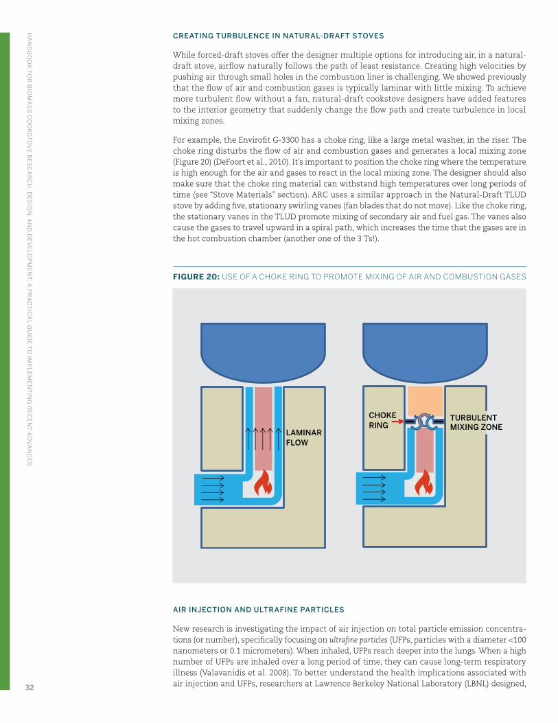
CREATING TURBULENCE IN NATURAL-DRAFT STOVES
While forced-draft stoves offer the designer multiple options for introducing air, in a natural- draft stove, airflow naturally follows the path of least resistance. Creating high velocities by pushing air through small holes in the combustion liner is challenging. We showed previously that the flow of air and combustion gases is typically laminar with little mixing. To achieve more turbulent flow without a fan, natural-draft cookstove designers have added features to the interior geometry that suddenly change the flow path and create turbulence in local mixing zones.
For example, the Envirofit G-3300 has a choke ring, like a large metal washer, in the riser. The choke ring disturbs the flow of air and combustion gases and generates a local mixing zone (Figure 20) (DeFoort et al., 2010). It’s important to position the choke ring where the temperature is high enough for the air and gases to react in the local mixing zone. The designer should also make sure that the choke ring material can withstand high temperatures over long periods of time (see “Stove Materials” section). ARC uses a similar approach in the Natural-Draft TLUD stove by adding five, stationary swirling vanes (fan blades that do not move). Like the choke ring, the stationary vanes in the TLUD promote mixing of secondary air and fuel gas. The vanes also cause the gases to travel upward in a spiral path, which increases the time that the gases are in the hot combustion chamber (another one of the 3 Ts!).
FIGURE 20: USE OF A CHOKE RING TO PROMOTE MIXING OF AIR AND COMBUSTION GASES
AIR INJECTION AND ULTRAFINE PARTICLES
New research is investigating the impact of air injection on total particle emission concentra-tions (or number), specifically focusing on ultrafine particles (UFPs, particles with a diameter <100 nanometers or 0.1 micrometers). When inhaled, UFPs reach deeper into the lungs. When a high number of UFPs are inhaled over a long period of time, they can cause long-term respiratory illness (Valavanidis et al. 2008). To better understand the health implications associated with air injection and UFPs, researchers at Lawrence Berkeley National Laboratory (LBNL) designed,
LAMINARFLOW
TURBULENTMIXING ZONE
CHOKERING
HA
ND
BO
OK
FOR
BIO
MA
SS
CO
OK
ST
OV
E R
ES
EA
RC
H, D
ES
IGN
, AN
D D
EV
ELO
PM
EN
T: A
PR
AC
TIC
AL G
UID
E T
O IM
PL
EM
EN
TIN
G R
EC
EN
T A
DV
AN
CE
S
32
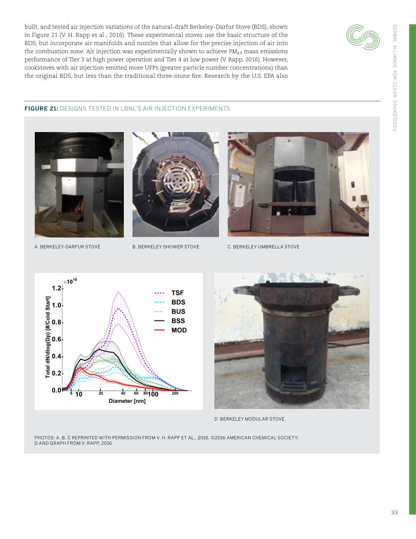
built, and tested air injection variations of the natural-draft Berkeley-Darfur Stove (BDS), shown in Figure 21 (V. H. Rapp et al., 2016). These experimental stoves use the basic structure of the BDS, but incorporate air manifolds and nozzles that allow for the precise injection of air into the combustion zone. Air injection was experimentally shown to achieve PM2.5 mass emissions performance of Tier 3 at high power operation and Tier 4 at low power (V. Rapp, 2016). However, cookstoves with air injection emitted more UFPs (greater particle number concentrations) than the original BDS, but less than the traditional three-stone fire. Research by the U.S. EPA also
D. BERKELEY MODULAR STOVE
PHOTOS: A, B, C REPRINTED WITH PERMISSION FROM V. H. RAPP ET AL., 2016. ©2016 AMERICAN CHEMICAL SOCIETY; D AND GRAPH FROM V. RAPP, 2016
C. BERKELEY UMBRELLA STOVEB. BERKELEY SHOWER STOVEA. BERKELEY-DARFUR STOVE
FIGURE 21: DESIGNS TESTED IN LBNL’S AIR INJECTION EXPERIMENTS
GLO
BA
L AL
LIA
NC
E FO
R C
LE
AN
CO
OK
ST
OV
ES
33
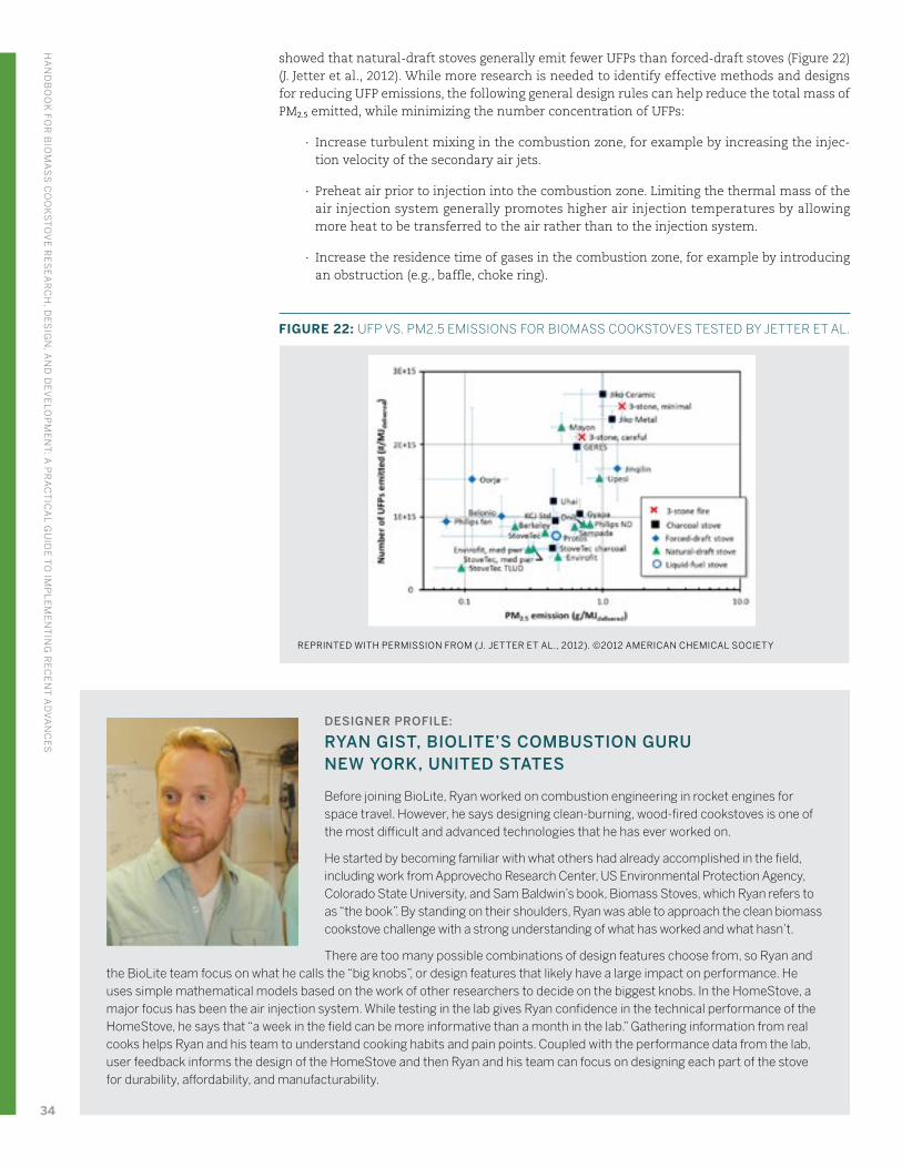
showed that natural-draft stoves generally emit fewer UFPs than forced-draft stoves (Figure 22) (J. Jetter et al., 2012). While more research is needed to identify effective methods and designs for reducing UFP emissions, the following general design rules can help reduce the total mass of PM2.5 emitted, while minimizing the number concentration of UFPs:
∙ Increase turbulent mixing in the combustion zone, for example by increasing the injec-tion velocity of the secondary air jets.
∙ Preheat air prior to injection into the combustion zone. Limiting the thermal mass of the air injection system generally promotes higher air injection temperatures by allowing more heat to be transferred to the air rather than to the injection system.
∙ Increase the residence time of gases in the combustion zone, for example by introducing an obstruction (e.g., baffle, choke ring).
DESIGNER PROFILE:
RYAN GIST, BIOLITE’S COMBUSTION GURU NEW YORK, UNITED STATES
Before joining BioLite, Ryan worked on combustion engineering in rocket engines for space travel. However, he says designing clean-burning, wood-fired cookstoves is one of the most difficult and advanced technologies that he has ever worked on.
He started by becoming familiar with what others had already accomplished in the field, including work from Approvecho Research Center, US Environmental Protection Agency, Colorado State University, and Sam Baldwin’s book, Biomass Stoves, which Ryan refers to as “the book”. By standing on their shoulders, Ryan was able to approach the clean biomass cookstove challenge with a strong understanding of what has worked and what hasn’t.
There are too many possible combinations of design features choose from, so Ryan and the BioLite team focus on what he calls the “big knobs”, or design features that likely have a large impact on performance. He uses simple mathematical models based on the work of other researchers to decide on the biggest knobs. In the HomeStove, a major focus has been the air injection system. While testing in the lab gives Ryan confidence in the technical performance of the HomeStove, he says that “a week in the field can be more informative than a month in the lab.” Gathering information from real cooks helps Ryan and his team to understand cooking habits and pain points. Coupled with the performance data from the lab, user feedback informs the design of the HomeStove and then Ryan and his team can focus on designing each part of the stove for durability, affordability, and manufacturability.
REPRINTED WITH PERMISSION FROM (J. JETTER ET AL., 2012). ©2012 AMERICAN CHEMICAL SOCIETY
FIGURE 22: UFP VS. PM2.5 EMISSIONS FOR BIOMASS COOKSTOVES TESTED BY JETTER ET AL.
HA
ND
BO
OK
FOR
BIO
MA
SS
CO
OK
ST
OV
E R
ES
EA
RC
H, D
ES
IGN
, AN
D D
EV
ELO
PM
EN
T: A
PR
AC
TIC
AL G
UID
E T
O IM
PL
EM
EN
TIN
G R
EC
EN
T A
DV
AN
CE
S
34
DESIGN PROCESS
Performance
∙ Which approaches for mixing could be tested in your stove design?
∙ Can you consult a testing center about how these changes impact performance?
Availability
∙ Are components for mixing (e.g., fans, durable metals) reliably available within your country? If not, what other products have similar components that you can use for pro-totyping and testing?
Usability
∙ Will the design features to improve mixing affect the user experience (e.g., create addi-tional sound, make it difficult to clean the stove)?
∙ Will an air injection system require that the user has access to electricity? Or connect the stove to a solar panel for battery charging?
Manufacturing
∙ Will design features to improve mixing require additional equipment or expertise in your manufacturing process?
∙ How can your manufacturing process be updated to maintain tight tolerances needed for precision air injection parts (e.g., air injection ports)?
Durability
∙ Are mixing features that are exposed to the combustion environment made of a tempera-ture resistant material?
∙ Are electrical components isolated from high temperature areas of the cookstove?
∙ If an electrical or mechanical component (e.g., electric fan) fails, can the user access maintenance or replacement parts?
Safety
∙ Are electrical components isolated and protected to avoid hazards to the user?
Affordability
∙ Can you improve mixing without greatly affecting the affordability of your product?
∙ If enhanced mixing increases the product cost, is there an added value to offer your customer?
GLO
BA
L AL
LIA
NC
E FO
R C
LE
AN
CO
OK
ST
OV
ES
35
2.6 Stove Materials
CONTEXT
The high temperature and corrosive environment in a biomass cookstove means that materials are critical to stove performance, user satisfaction, safety, as well as manufacturing and afford-ability. Suitable materials allow users to consistently perform cooking tasks while minimizing safety risks, failures, and deterioration. Suitable materials assure users of product quality and that this is an appliance to be proud to own. Manufacturers must also be prepared to support customers with service and replacement parts.
ENGINEERING PRINCIPLES
Before choosing materials to try, consider how the materials will function and refer to the design requirements. If the design requirements include a measurable quantity, it will be easier to ensure that requirements are met. Some examples, in addition to those in “The Design Process” section are:
∙ External temperatures will not exceed 65°C
∙ Will operate under normal daily use without material failure for at least 2 years
∙ Will reach cooking temperature in less than 10 minutes
A single material can have some characteristics that are well suited for cookstoves, and other characteristics that are not. Designers may use a combination of materials to leverage the desirable characteristics of each material. For example, good insulating materials often have low strength and durability (e.g., low density clay, porous stones, glass fiber blanket). Some insu-lators can be damaged when exposed to flames and high temperatures. Therefore, designers can sandwich insulation between a layer to sustain high temperatures (refractory) and a layer to provide high strength and easy handling (cladding). Insulation materials can also pose health and safety hazards if they are not contained and isolated, and workers should be protected when assembling the cookstove. Table 7 provides some examples of potential materials and their advantages and disadvantages.
A major function of cookstove materials is to manage the flow of heat (heat transfer) through different parts of the stove. Ideally, 100% of heat generated would be transferred to the pot as useful energy. In reality, heat follows many paths through the stove, to the pot, and to the surroundings (heat losses). Laboratory testing shows that only 15% of energy produced by a carefully tended three stone fire is transferred into the cooking pot, and 85% is lost to the envi-ronment (J. Jetter et al., 2012). Similarly, for an insulated rocket stove with pot skirt, MacCarty estimated that 35% of the total heat generated is transferred to the pot, and 65% lost to the surroundings (Nordica Ann MacCarty, 2013). While this seems like a modest increase over the three stone fire, and there are still large losses to the environment, the rocket stove reduces fuel consumption by nearly 60%.
There are three modes of heat transfer: conduction, convection, and radiation. Conduction is the transfer of heat through a substance. A hot stone will conduct heat to your hand when you make contact with it. Convection is the transfer of heat to or from a fluid passing along a hot or cold surface. As water boils in a kettle, hot water at the bottom rises, and then mixes with and heats the cool water above. Radiation is the transfer of heat from a hot surface to a cool surface through electromagnetic waves. The warming of your skin when you stand near a fire is due to the radiant heat emitted from the fire.
Figure 23 illustrates the heat transfer and temperature distribution through the wall of a cook-stove. Hot gases in the stove heat the inside surface of the combustion liner, mainly through radiation and convection. In this example, heat conducts through the refractory ceramic liner, insulation, and exterior metal cladding layers. Heat escapes the surface of the cladding mostly through radiation and convection.
HA
ND
BO
OK
FOR
BIO
MA
SS
CO
OK
ST
OV
E R
ES
EA
RC
H, D
ES
IGN
, AN
D D
EV
ELO
PM
EN
T: A
PR
AC
TIC
AL G
UID
E T
O IM
PL
EM
EN
TIN
G R
EC
EN
T A
DV
AN
CE
S
36
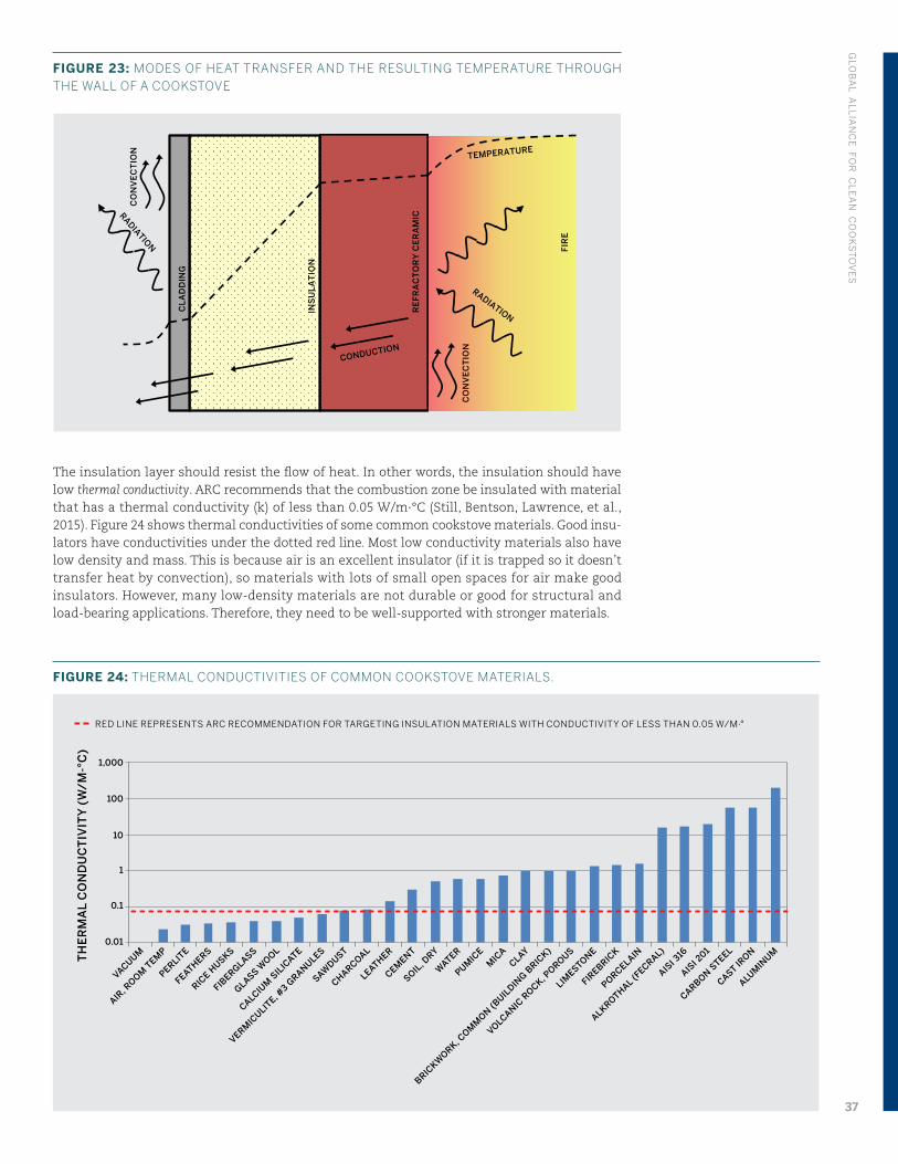
FIGURE 23: MODES OF HEAT TRANSFER AND THE RESULTING TEMPERATURE THROUGH THE WALL OF A COOKSTOVE
The insulation layer should resist the flow of heat. In other words, the insulation should have low thermal conductivity. ARC recommends that the combustion zone be insulated with material that has a thermal conductivity (k) of less than 0.05 W/m∙°C (Still, Bentson, Lawrence, et al., 2015). Figure 24 shows thermal conductivities of some common cookstove materials. Good insu-lators have conductivities under the dotted red line. Most low conductivity materials also have low density and mass. This is because air is an excellent insulator (if it is trapped so it doesn’t transfer heat by convection), so materials with lots of small open spaces for air make good insulators. However, many low-density materials are not durable or good for structural and load-bearing applications. Therefore, they need to be well-supported with stronger materials.
RE
FR
AC
TO
RY
CE
RA
MIC
INS
UL
AT
ION
CL
AD
DIN
G
CO
NV
EC
TIO
N
FIR
E
CO
NV
EC
TIO
N
RADIATION
RADIATION
TEMPERATURE
CONDUCTION
TH
ER
MA
L C
ON
DU
CT
IVIT
Y (
W/
M-°
C)
1,000
100
10
1
0.1
0.01
VACUUM
AIR, R
OOM T
EMP
PERLITE
FEATHERS
RICE H
USKS
FIBERGLASS
GLASS WOOL
CALCIUM
SIL
ICATE
VERMIC
ULITE, #
3 GRANULES
SAWDUST
CHARCOAL
LEATHER
CEMENT
SOIL, D
RY
WATER
PUMIC
EM
ICA
CLAY
BRICKW
ORK, COM
MON (B
UILDIN
G BRIC
K)
VOLCANIC R
OCK, POROUS
LIMESTONE
FIREBRIC
K
PORCELAIN
ALKROTHAL (FECRAL)
AISI 3
16
AISI 2
01
CARBON STEEL
CAST IRON
ALUMIN
UM
RED LINE REPRESENTS ARC RECOMMENDATION FOR TARGETING INSULATION MATERIALS WITH CONDUCTIVITY OF LESS THAN 0.05 W/M∙°
FIGURE 24: THERMAL CONDUCTIVITIES OF COMMON COOKSTOVE MATERIALS.
GLO
BA
L AL
LIA
NC
E FO
R C
LE
AN
CO
OK
ST
OV
ES
37
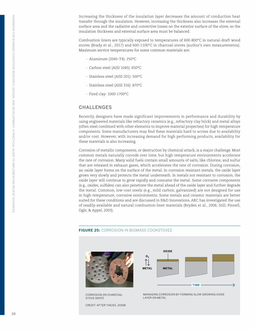
Increasing the thickness of the insulation layer decreases the amount of conduction heat transfer through the insulation. However, increasing the thickness also increases the external surface area and the radiative and convective losses on the exterior surface of the stove, so the insulation thickness and external surface area must be balanced.
Combustion liners are typically exposed to temperatures of 600-800°C in natural-draft wood stoves (Brady et al., 2017) and 600-1100°C in charcoal stoves (author’s own measurements). Maximum service temperatures for some common materials are:
∙ Aluminum (2045-T4): 250°C
∙ Carbon steel (AISI 1045): 650°C
∙ Stainless steel (AISI 201): 500°C
∙ Stainless steel (AISI 316): 870°C
∙ Fired clay: 1000-1700°C
CHALLENGES
Recently, designers have made significant improvements in performance and durability by using engineered materials like refractory ceramics (e.g., refractory clay brick) and metal alloys (often steel combined with other elements to improve material properties) for high temperature components. Some manufacturers may find these materials hard to access due to availability and/or cost. However, with increasing demand for high performing products, availability for these materials is also increasing.
Corrosion of metallic components, or destruction by chemical attack, is a major challenge. Most common metals naturally corrode over time, but high temperature environments accelerate the rate of corrosion. Many solid fuels contain small amounts of salts, like chlorine, and sulfur that are released in exhaust gases, which accelerates the rate of corrosion. During corrosion, an oxide layer forms on the surface of the metal. In corrosion resistant metals, the oxide layer grows very slowly and protects the metal underneath. In metals not resistant to corrosion, the oxide layer will continue to grow rapidly and consume the metal. Some corrosive components (e.g., oxides, sulfides) can also penetrate the metal ahead of the oxide layer and further degrade the metal. Common, low-cost steels (e.g., mild carbon, galvanized) are not designed for use in high-temperature, corrosive environments. Some metals and ceramic materials are better suited for these conditions and are discussed in R&D Innovations. ARC has investigated the use of readily-available and natural combustion-liner materials (Bryden et al., 2006; Still, Pinnell, Ogle, & Appel, 2003).
CORROSION ON CHARCOAL STOVE GRATE
CREDIT: AFTER THEISS, 2016B
METAL
TIME
OXIDE
METAL
O2
MANAGING CORROSION BY FORMING SLOW-GROWING OXIDE LAYER ON METAL
FIGURE 25: CORROSION IN BIOMASS COOKSTOVES
HA
ND
BO
OK
FOR
BIO
MA
SS
CO
OK
ST
OV
E R
ES
EA
RC
H, D
ES
IGN
, AN
D D
EV
ELO
PM
EN
T: A
PR
AC
TIC
AL G
UID
E T
O IM
PL
EM
EN
TIN
G R
EC
EN
T A
DV
AN
CE
S
38
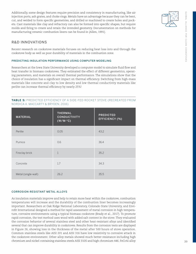
Additionally, some design features require precision and consistency in manufacturing, like air injection ports, ash grates, and choke rings. Metals have an advantage because they can be bent, cut, and welded to form specific geometries, and drilled or machined to create holes and pock-ets. Cast materials like clay and refractory can also be formed into specific shapes, but require molds and firing to create and retain the intended geometry. Documentation on methods for manufacturing ceramic combustion liners can be found in (Allen, 1991).
R&D INNOVATIONS
Recent research on cookstove materials focuses on reducing heat loss into and through the cookstove body as well as poor durability of materials in the combustion zone.
PREDICTING INSULATION PERFORMANCE USING COMPUTER MODELING
Researchers at the Iowa State University developed a computer model to simulate fluid flow and heat transfer in biomass cookstoves. They estimated the effect of different geometrics, operat-ing parameters, and materials on overall thermal performance. The simulations show that the choice of insulation has a significant impact on thermal efficiency. Switching from high-mass materials like concrete and clay to low density and low thermal conductivity materials like perlite can increase thermal efficiency by nearly 25%!
TABLE 5: PREDICTED EFFICIENCY OF A SIDE-FED ROCKET STOVE (RECREATED FROM NORDICA A. MACCARTY & BRYDEN, 2016)
MATERIALTHERMAL CONDUCTIVITY (W/M-°C)
PREDICTED EFFICIENCY (%)
Perlite 0.05 43.2
Pumice 0.6 36.4
Fireclay brick 1 35.2
Concrete 1.7 34.3
Metal (single-wall) 26.2 35.5
CORROSION-RESISTANT METAL ALLOYS
As insulation materials improve and help to retain more heat within the cookstove, combustion temperatures will increase and the durability of the combustion liner becomes increasingly important. Researchers at Oak Ridge National Laboratory, Colorado State University, and Envi-rofit International designed a method for rapid assessment of metal corrosion in high tempera-ture, corrosive environments using a typical biomass cookstove (Brady et al., 2017). To promote rapid corrosion, the test method uses wood with added salt content in the stove. They evaluated the corrosion behavior of several stainless steel and other heat-resistant alloys and identified several that can improve durability in cookstoves. Results from the corrosion tests are displayed in Figure 26, showing loss in the thickness of the metal after 500 hours of stove operation. Common stainless steels like AISI 201 and AISI 316 have low resistivity to corrosive attack in the cookstove environment. Other alloy metals showed much better resistance including high chromium and nickel containing stainless steels AISI 310S and high chromium 446. FeCrAl alloy
GLO
BA
L AL
LIA
NC
E FO
R C
LE
AN
CO
OK
ST
OV
ES
39
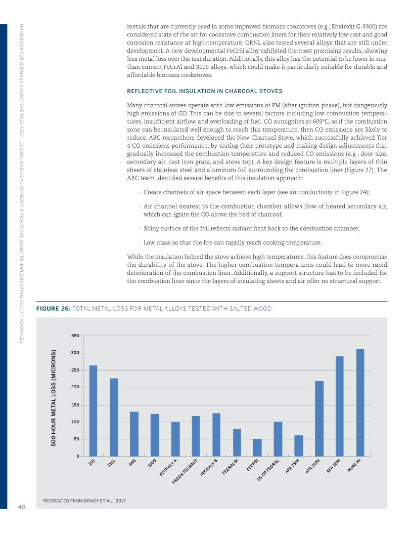
metals that are currently used in some improved biomass cookstoves (e.g., Envirofit G-3300) are considered state of the art for cookstove combustion liners for their relatively low cost and good corrosion resistance at high-temperature. ORNL also tested several alloys that are still under development. A new developmental FeCrSi alloy exhibited the most promising results, showing less metal loss over the test duration. Additionally, this alloy has the potential to be lower in cost than current FeCrAl and 310S alloys, which could make it particularly suitable for durable and affordable biomass cookstoves.
REFLECTIVE FOIL INSULATION IN CHARCOAL STOVES
Many charcoal stoves operate with low emissions of PM (after ignition phase), but dangerously high emissions of CO. This can be due to several factors including low combustion tempera-tures, insufficient airflow, and overloading of fuel. CO autoignites at 609°C, so if the combustion zone can be insulated well enough to reach this temperature, then CO emissions are likely to reduce. ARC researchers developed the New Charcoal Stove, which successfully achieved Tier 4 CO emissions performance, by testing their prototype and making design adjustments that gradually increased the combustion temperature and reduced CO emissions (e.g., door size, secondary air, cast iron grate, and stove top). A key design feature is multiple layers of thin sheets of stainless steel and aluminum foil surrounding the combustion liner (Figure 27). The ARC team identified several benefits of this insulation approach:
∙ Create channels of air space between each layer (see air conductivity in Figure 24);
∙ Air channel nearest to the combustion chamber allows flow of heated secondary air, which can ignite the CO above the bed of charcoal;
∙ Shiny surface of the foil reflects radiant heat back to the combustion chamber;
∙ Low mass so that the fire can rapidly reach cooking temperature.
While the insulation helped the stove achieve high temperatures, this feature does compromise the durability of the stove. The higher combustion temperatures could lead to more rapid deterioration of the combustion liner. Additionally, a support structure has to be included for the combustion liner since the layers of insulating sheets and air offer no structural support.
50
0 H
OU
R M
ETA
L LO
SS
(M
ICR
ON
S)
-350
-300
-250
-200
-150
-100
-50
0
201316
L446
310S
FECRALY A
PREOX FECRALY
FECRALY B
FECRALSI
FECRSI
25 CR F
ECRAL
AFA 2
5NI
AFA 2
0NI
AFA 12
NI
PURE NI
RECREATED FROM BRADY ET AL., 2017
FIGURE 26: TOTAL METAL LOSS FOR METAL ALLOYS TESTED WITH SALTED WOOD
HA
ND
BO
OK
FOR
BIO
MA
SS
CO
OK
ST
OV
E R
ES
EA
RC
H, D
ES
IGN
, AN
D D
EV
ELO
PM
EN
T: A
PR
AC
TIC
AL G
UID
E T
O IM
PL
EM
EN
TIN
G R
EC
EN
T A
DV
AN
CE
S
40
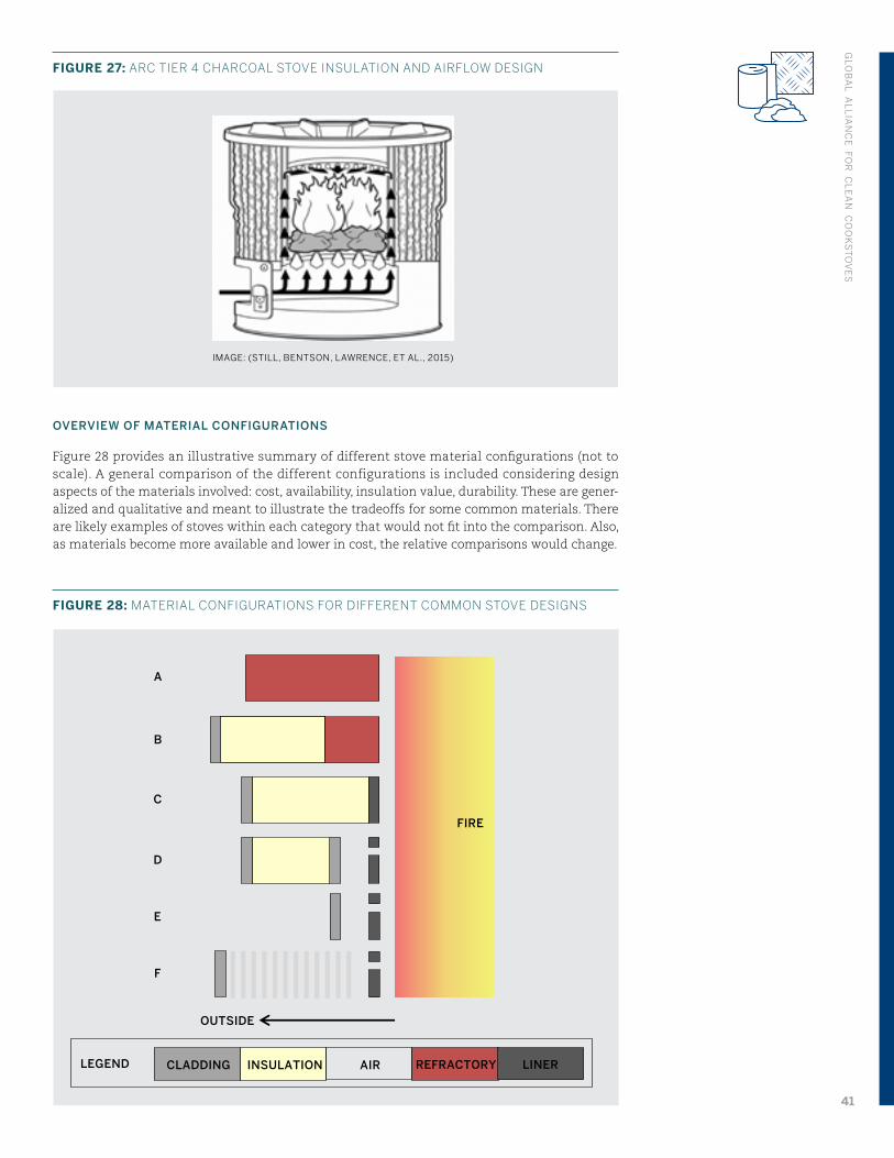
FIGURE 27: ARC TIER 4 CHARCOAL STOVE INSULATION AND AIRFLOW DESIGN
OVERVIEW OF MATERIAL CONFIGURATIONS
Figure 28 provides an illustrative summary of different stove material configurations (not to scale). A general comparison of the different configurations is included considering design aspects of the materials involved: cost, availability, insulation value, durability. These are gener-alized and qualitative and meant to illustrate the tradeoffs for some common materials. There are likely examples of stoves within each category that would not fit into the comparison. Also, as materials become more available and lower in cost, the relative comparisons would change.
FIGURE 28: MATERIAL CONFIGURATIONS FOR DIFFERENT COMMON STOVE DESIGNS
IMAGE: (STILL, BENTSON, LAWRENCE, ET AL., 2015)
LEGEND
OUTSIDE
B
C
D
E
F
A
FIRE
REFRACTORY INSULATIONCLADDING LINERAIR
GLO
BA
L AL
LIA
NC
E FO
R C
LE
AN
CO
OK
ST
OV
ES
41
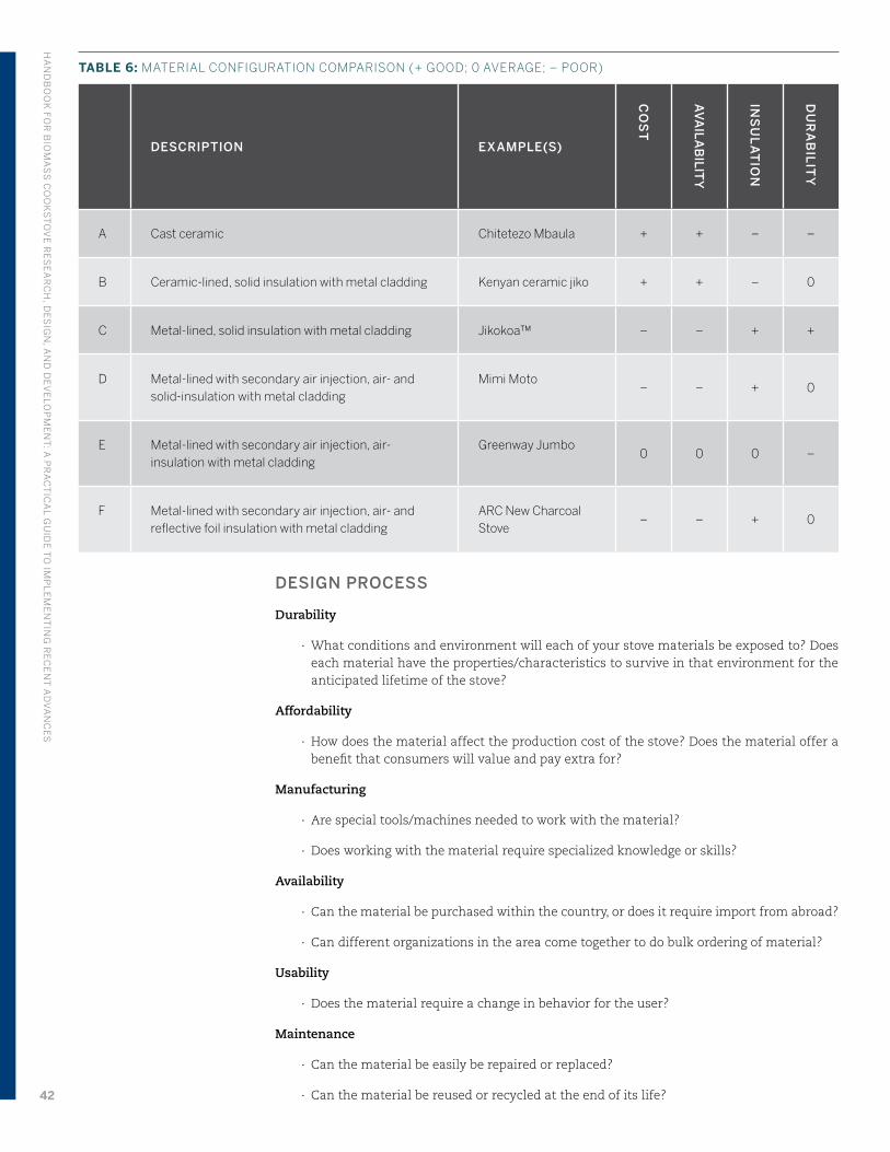
TABLE 6: MATERIAL CONFIGURATION COMPARISON (+ GOOD; 0 AVERAGE; – POOR)
DESCRIPTION EXAMPLE(S)
CO
ST
AV
AIL
AB
ILITY
INS
UL
AT
ION
DU
RA
BIL
ITY
A Cast ceramic Chitetezo Mbaula + + – –
B Ceramic-lined, solid insulation with metal cladding Kenyan ceramic jiko + + – 0
C Metal-lined, solid insulation with metal cladding Jikokoa™ – – + +
D Metal-lined with secondary air injection, air- and solid-insulation with metal cladding
Mimi Moto– – + 0
E Metal-lined with secondary air injection, air-insulation with metal cladding
Greenway Jumbo0 0 0 –
F Metal-lined with secondary air injection, air- and reflective foil insulation with metal cladding
ARC New Charcoal Stove
– – + 0
DESIGN PROCESS
Durability
∙ What conditions and environment will each of your stove materials be exposed to? Does each material have the properties/characteristics to survive in that environment for the anticipated lifetime of the stove?
Affordability
∙ How does the material affect the production cost of the stove? Does the material offer a benefit that consumers will value and pay extra for?
Manufacturing
∙ Are special tools/machines needed to work with the material?
∙ Does working with the material require specialized knowledge or skills?
Availability
∙ Can the material be purchased within the country, or does it require import from abroad?
∙ Can different organizations in the area come together to do bulk ordering of material?
Usability
∙ Does the material require a change in behavior for the user?
Maintenance
∙ Can the material be easily be repaired or replaced?
∙ Can the material be reused or recycled at the end of its life?
HA
ND
BO
OK
FOR
BIO
MA
SS
CO
OK
ST
OV
E R
ES
EA
RC
H, D
ES
IGN
, AN
D D
EV
ELO
PM
EN
T: A
PR
AC
TIC
AL G
UID
E T
O IM
PL
EM
EN
TIN
G R
EC
EN
T A
DV
AN
CE
S
42
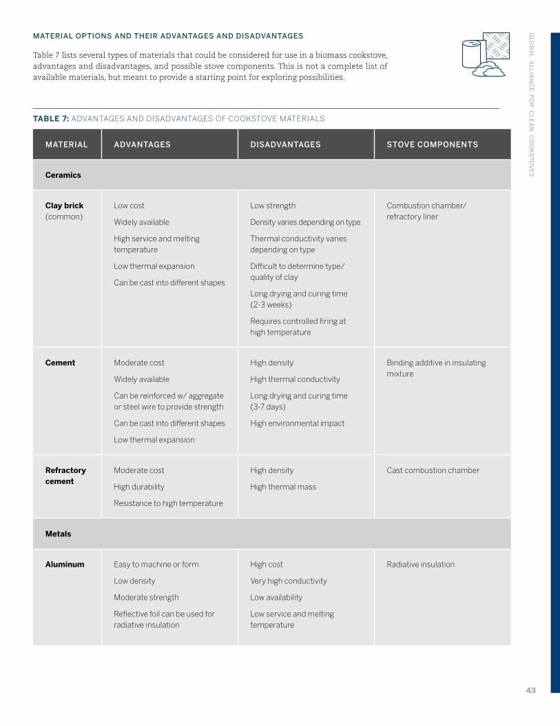
MATERIAL OPTIONS AND THEIR ADVANTAGES AND DISADVANTAGES
Table 7 lists several types of materials that could be considered for use in a biomass cookstove, advantages and disadvantages, and possible stove components. This is not a complete list of available materials, but meant to provide a starting point for exploring possibilities.
TABLE 7: ADVANTAGES AND DISADVANTAGES OF COOKSTOVE MATERIALS
MATERIAL ADVANTAGES DISADVANTAGES STOVE COMPONENTS
Ceramics
Clay brick (common)
Low cost
Widely available
High service and melting temperature
Low thermal expansion
Can be cast into different shapes
Low strength
Density varies depending on type
Thermal conductivity varies depending on type
Difficult to determine type/ quality of clay
Long drying and curing time (2-3 weeks)
Requires controlled firing at high temperature
Combustion chamber/ refractory liner
Cement Moderate cost
Widely available
Can be reinforced w/ aggregate or steel wire to provide strength
Can be cast into different shapes
Low thermal expansion
High density
High thermal conductivity
Long drying and curing time (3-7 days)
High environmental impact
Binding additive in insulating mixture
Refractory cement
Moderate cost
High durability
Resistance to high temperature
High density
High thermal mass
Cast combustion chamber
Metals
Aluminum Easy to machine or form
Low density
Moderate strength
Reflective foil can be used for radiative insulation
High cost
Very high conductivity
Low availability
Low service and melting temperature
Radiative insulation
GLO
BA
L AL
LIA
NC
E FO
R C
LE
AN
CO
OK
ST
OV
ES
43
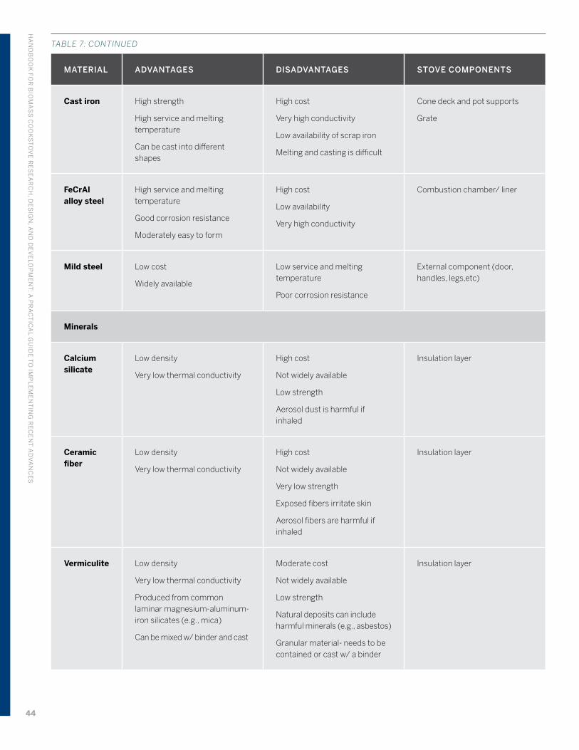
MATERIAL ADVANTAGES DISADVANTAGES STOVE COMPONENTS
Cast iron High strength
High service and melting temperature
Can be cast into different shapes
High cost
Very high conductivity
Low availability of scrap iron
Melting and casting is difficult
Cone deck and pot supports
Grate
FeCrAl alloy steel
High service and melting temperature
Good corrosion resistance
Moderately easy to form
High cost
Low availability
Very high conductivity
Combustion chamber/ liner
Mild steel Low cost
Widely available
Low service and melting temperature
Poor corrosion resistance
External component (door, handles, legs,etc)
Minerals
Calcium silicate
Low density
Very low thermal conductivity
High cost
Not widely available
Low strength
Aerosol dust is harmful if inhaled
Insulation layer
Ceramic fiber
Low density
Very low thermal conductivity
High cost
Not widely available
Very low strength
Exposed fibers irritate skin
Aerosol fibers are harmful if inhaled
Insulation layer
Vermiculite Low density
Very low thermal conductivity
Produced from common laminar magnesium-aluminum-iron silicates (e.g., mica)
Can be mixed w/ binder and cast
Moderate cost
Not widely available
Low strength
Natural deposits can include harmful minerals (e.g., asbestos)
Granular material- needs to be contained or cast w/ a binder
Insulation layer
TABLE 7: CONTINUED
HA
ND
BO
OK
FOR
BIO
MA
SS
CO
OK
ST
OV
E R
ES
EA
RC
H, D
ES
IGN
, AN
D D
EV
ELO
PM
EN
T: A
PR
AC
TIC
AL G
UID
E T
O IM
PL
EM
EN
TIN
G R
EC
EN
T A
DV
AN
CE
S
44
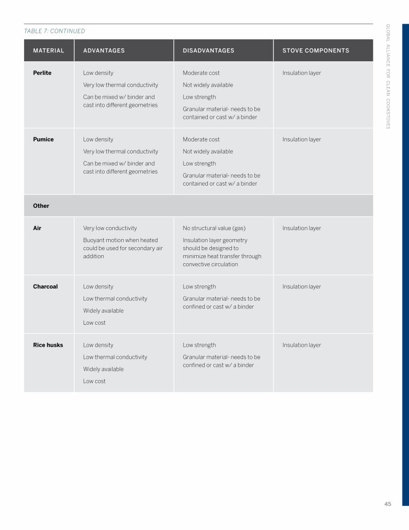
MATERIAL ADVANTAGES DISADVANTAGES STOVE COMPONENTS
Perlite Low density
Very low thermal conductivity
Can be mixed w/ binder and cast into different geometries
Moderate cost
Not widely available
Low strength
Granular material- needs to be contained or cast w/ a binder
Insulation layer
Pumice Low density
Very low thermal conductivity
Can be mixed w/ binder and cast into different geometries
Moderate cost
Not widely available
Low strength
Granular material- needs to be contained or cast w/ a binder
Insulation layer
Other
Air Very low conductivity
Buoyant motion when heated could be used for secondary air addition
No structural value (gas)
Insulation layer geometry should be designed to minimize heat transfer through convective circulation
Insulation layer
Charcoal Low density
Low thermal conductivity
Widely available
Low cost
Low strength
Granular material- needs to be confined or cast w/ a binder
Insulation layer
Rice husks Low density
Low thermal conductivity
Widely available
Low cost
Low strength
Granular material- needs to be confined or cast w/ a binder
Insulation layer
TABLE 7: CONTINUED
GLO
BA
L AL
LIA
NC
E FO
R C
LE
AN
CO
OK
ST
OV
ES
45
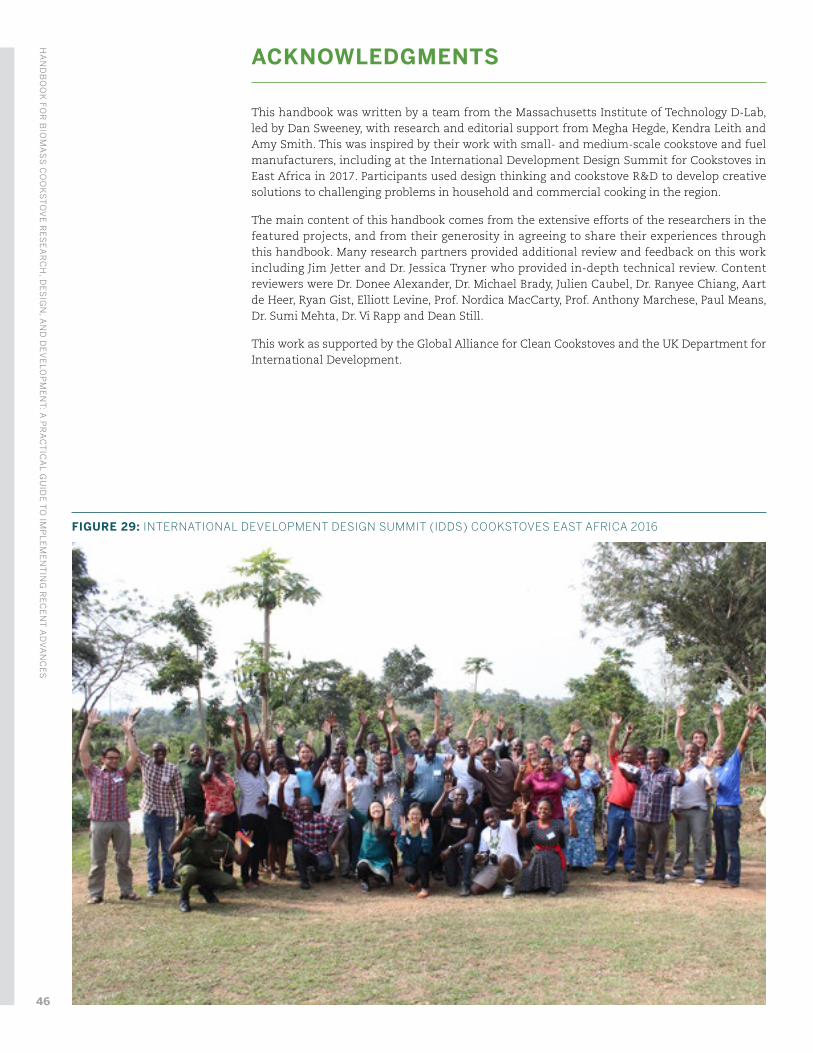
ACKNOWLEDGMENTS
This handbook was written by a team from the Massachusetts Institute of Technology D-Lab, led by Dan Sweeney, with research and editorial support from Megha Hegde, Kendra Leith and Amy Smith. This was inspired by their work with small- and medium-scale cookstove and fuel manufacturers, including at the International Development Design Summit for Cookstoves in East Africa in 2017. Participants used design thinking and cookstove R&D to develop creative solutions to challenging problems in household and commercial cooking in the region.
The main content of this handbook comes from the extensive efforts of the researchers in the featured projects, and from their generosity in agreeing to share their experiences through this handbook. Many research partners provided additional review and feedback on this work including Jim Jetter and Dr. Jessica Tryner who provided in-depth technical review. Content reviewers were Dr. Donee Alexander, Dr. Michael Brady, Julien Caubel, Dr. Ranyee Chiang, Aart de Heer, Ryan Gist, Elliott Levine, Prof. Nordica MacCarty, Prof. Anthony Marchese, Paul Means, Dr. Sumi Mehta, Dr. Vi Rapp and Dean Still.
This work as supported by the Global Alliance for Clean Cookstoves and the UK Department for International Development.
FIGURE 29: INTERNATIONAL DEVELOPMENT DESIGN SUMMIT (IDDS) COOKSTOVES EAST AFRICA 2016
HA
ND
BO
OK
FOR
BIO
MA
SS
CO
OK
ST
OV
E R
ES
EA
RC
H, D
ES
IGN
, AN
D D
EV
ELO
PM
EN
T: A
PR
AC
TIC
AL G
UID
E T
O IM
PL
EM
EN
TIN
G R
EC
EN
T A
DV
AN
CE
S
46
References
Agenbroad, J. N. (2010). A Simplified Model for Understanding Natural Convection Driven Biomass Cooking Stoves. Colorado State University Fort Collins, Colorado. Colorado State University. http://doi.org/10.1017/CBO9781107415324.004
Allen, H. (1991). The Kenya Ceramic Jiko: A manual for stovemakers. New York.
Anderson, P. S., Reed, T. B., & Wever, P. W. (2007). Micro-Gasification: What it is and why it works. Boiling Point, (53), 35–37. Retrieved from http://www.hedon.info/docs/BP53-Anderson-14.pdf
Ashden. (2015). BURN Manufacturing, Kenya. Retrieved from www.ashden.org/winners/Burn15
Baldwin, S. F. (1987). Biomass Stoves, Engineering Design, Development and Dissemination.
Banzaert, A. (2013). Viability of Waste-Based Cooking Fuels for Developing Countries : Combustion Emissions and Field Feasibility. Massachusetts Institute of Technology.
Brady, M. P., Banta, K., Mizia, J., Lorenz, N., Leonard, D. N., Yamamoto, Y., … Keiser, J. R. (2017). Alloy Corrosion Considerations in Low-Cost, Clean Biomass Cookstoves for the Developing World. Energy for Sustainable Development, 37, 20–32. http://doi.org/10.1016/j.esd.2016.12.002
Bryden, M., Still, D., Scott, P., Hoffa, G., Ogle, D., Bailis, R., & Goyer, K. (2006). Design Principles for Wood Burning Cook Stoves. Retrieved from http://aprovecho.org/publications-3/
Dale, B. (2013, November). How BioLite adapted its camp stove to save lives in the developing world. Technical.ly. Retrieved from https://technical.ly/brooklyn/2013/11/11/biolite-product-history/
DeFoort, M. W., Willson, B. D., Lorenz, N., Brady, M. P., Marchese, A. J., & Miller-Lionberg, D. D. (2010). Cook stove assembly. United States. Retrieved from https://docs.google.com/viewer?url=patentimages.storage.googleapis.com/pdfs/US20100258104.pdf
Domalski, E., Jobe, T., & Milne, T. (1987). Thermodynamic Data for biomass conversion and waste incineration. Solar Energy, 326.
Emmons, H. W., & Atreya, A. (1982). The science of wood combustion. Proceedings of the Indian Academy of Sciences Section C: Engineering Sciences, 5(4), 259–268. http://doi.org/10.1007/BF02904581
Gist, R., Iyer, V., Smith, K., Masera, O., & Berrueta, V. (2015). Heart of the Hearth : Making the Popular Clean , not the Clean Popular. Kirkland, WA: ETHOS Conference. Retrieved from https://www.energy.gov/sites/prod/files/2015/04/f21/cookstoves_gist_5213.pdf
Jetter, J. J., & Kariher, P. (2009). Solid-fuel household cook stoves: Characterization of performance and emissions. Biomass and Bioenergy, 33(2), 294–305. http://doi.org/10.1016/j.biombioe.2008.05.014
Jetter, J., Zhao, Y., Smith, K. R., Khan, B., Decarlo, P., Hays, M. D., … States, U. (2012). Pollutant Emissions and Energy Efficiency under Controlled Conditions for Household Biomass Cookstoves and Implications for Metrics Useful in Setting International Test Standards. Environmental Science & Technology, 46, 10827–10834. Retrieved from http://pubs.acs.org/doi/abs/10.1021/es301693f
MacCarty, N. A. (2013). A zonal model to aid in the design of household biomass cookstoves. Iowa State University. Retrieved from http://lib.dr.iastate.edu/etd/13589/
MacCarty, N. A., & Bryden, K. M. (2016). A generalized heat-transfer model for shielded-fire household cookstoves. Energy for Sustainable Development, 33, 96–107. http://doi.org/10.1016/j.esd.2016.03.003
GLO
BA
L AL
LIA
NC
E FO
R C
LE
AN
CO
OK
ST
OV
ES
47
Mauer, D. (2006). The Complete Idiot’s Guide to Grilling. DK Publishing. Retrieved from https://books.google.com/books?id=QRH_Y9ehYkgC
Means, P. (2016). Interview on 10 May 2016.
O’Shaughnessy, S. M., Deasy, M. J., Kinsella, C. E., Doyle, J. V., & Robinson, A. J. (2013). Small scale electricity generation from a portable biomass cookstove: Prototype design and preliminary results. Applied Energy, 102, 374–385. http://doi.org/10.1016/j.apenergy.2012.07.032
Posner, J. D. (2015). Multidisciplinary Design of an Innovative Natural Draft, Forced Diffusion Cookstove for Woody and Herbaceous Biomass Fuels. ETHOS. Kirkland, WA: ETHOS Conference. Retrieved from http://www.ethoscon.com/wp-content/uploads/2015/04/DOE-jonathan-posner-Multidisciplinary-design-of-an-innovative-natural-draft-forced-diffusion-cookstove-for-woody-and-herbaceous-biomass-fuels.pdf
Prapas, J., Baumgardner, M. E., Marchese, A. J., Willson, B., & DeFoort, M. (2014). Influence of chimneys on combustion characteristics of buoyantly driven biomass stoves. Energy for Sustainable Development, 23, 286–293. http://doi.org/10.1016/j.esd.2014.08.007
Pundle, A., Sullivan, B., Allawatt, G., Posner, J., & Kramlich, J. (2015). Computational Fluid Dynamic Modeling of a Natural Draft Cookstove for Efficiency Optimization and Emissions Reduction. Kirkland, WA: ETHOS Conference. Retrieved from http://www.ethoscon.com/wp-content/uploads/2015/04/Anamol-Pundle-Computational-Fluid-Dynamic-Modeling-of-a-Natural-Draft-Cookstove-for-Efficiency-Optimization-and-Emissions-Reduction.pdf
Rapp, V. (2016). An Affordable Advanced Biomass Cookstove with Thin Film Thermoelectric Generator (TEG). Kirkland, WA: ETHOS Conference. Retrieved from http://ethoscon.com/pdf/ETHOS/ETHOS2016/Rapp.pdf
Rapp, V. H., Caubel, J. J., Wilson, D. L., & Gadgil, A. J. (2016). Reducing Ultrafine Particle Emissions Using Air Injection in Wood-Burning Cookstoves. Environmental Science & Technology, 50(15), 8368–8374. http://doi.org/10.1021/acs.est.6b01333
Reed, T. B., & Larson, R. (1996). A wood-gas stove for developing countries. Energy for Sustainable Development, 3(2), 34–37. http://doi.org/10.1016/S0973-0826(08)60589-X
Roth, C. (2014). Micro-gasification: cooking with gas from dry biomass. Eschborn. Retrieved from https://energypedia.info/wiki/File:Micro_Gasification_2.0_Cooking_with_gas_from_dry_biomass.pdf
Rowe, D. M. (1978). Thermoelectric power generation. Proceedings of the Institution of Electrical Engineers, 125(11 R), 1113–1136. http://doi.org/10.1080/00107516108202661
Still, D. (2015). Five “Tier 4” Stoves Move Towards the Market. Kirkland, WA: ETHOS Conference. Retrieved from http://www.ethoscon.com/wp-content/uploads/2015/04/DOE-Dean-Still-five-Tier-four-stoves-move-toward-the-market.pdf
Still, D., Bentson, S., Lawrence, R. H., & Andreatta, D. (2015). Clean Burning Biomass Cookstoves. Retrieved from http://aprovecho.org/publications-3/
Still, D., Bentson, S., & Li, H. (2015). Results of Laboratory Testing of 15 Cookstove Designs in Accordance with the ISO/IWA Tiers of Performance. EcoHealth, 12(1), 12–24. http://doi.org/10.1007/s10393-014-0955-6
Still, D., MacCarty, N., Ogle, D., Bond, T., & Bryden, M. (2011). Test Results of Cook Stove Performance. Retrieved from http://aprovecho.org/publications-3/
Still, D., Pinnell, M., Ogle, D., & Appel, B. Van. (2003). Insulative ceramics for improved cooking stoves. Boiling Point, 49, 7–10. Retrieved from http://www.hedon.info/View+Article&itemId=9100
Sullivan, B. (2016). Development of Cookstove Emissions and Performance Testing Suite with Time-resolved Particulate Matter Analysis and Excess Air Estimation. University of Washington. Retrieved from https://digital.lib.washington.edu/researchworks/bitstream/handle/1773/36764/Sullivan_washington_0250O_16167.pdf?sequence=1
HA
ND
BO
OK
FOR
BIO
MA
SS
CO
OK
ST
OV
E R
ES
EA
RC
H, D
ES
IGN
, AN
D D
EV
ELO
PM
EN
T: A
PR
AC
TIC
AL G
UID
E T
O IM
PL
EM
EN
TIN
G R
EC
EN
T A
DV
AN
CE
S
48
Sullivan, B., Allawatt, G., Emery, A., Means, P., Posner, J., Sullivan, B., … Kramlich, J. (2017). Time-Resolved Particulate Emissions Monitoring of Cookstove Biomass Combustion Using a Tapered Element Oscillating Microbalance Time-Resolved Particulate Emissions Monitoring of Cookstove. Combustion Science and Technology, 189(6), 923–936. http://doi.org/10.1080/00102202.2016.1253564
Sutar, K. B., Kohli, S., Ravi, M. R., & Ray, A. (2015). Biomass cookstoves: A review of technical aspects, 41, 1128–1166. http://doi.org/10.1016/j.rser.2014.09.003
Theiss, T. (2016a). Materials for Metallic Combustors in Low-Cost, Clean Biomass Cookstoves. Kirkland, WA: ETHOS Conference. Retrieved from http://ethoscon.com/pdf/ETHOS/ETHOS2016/Theiss.pdf
Theiss, T. (2016b). Materials for Metallic Combustors in Low-Cost , Clean Biomass Cookstoves. In ETHOS.
Tryner, J. (2016). Combustion Phenomena in Biomass Gasifier Cookstoves. Retrieved from https://dspace.library.colostate.edu/handle/10217/176745
Tryner, J., & Marchese, A. J. (2016). Interview on 29 February 2016.
Tryner, J., Tillotson, J. W., Baumgardner, M. E., Mohr, J. T., DeFoort, M. W., & Marchese, A. J. (2016). The Effects of Air Flow Rates, Secondary Air Inlet Geometry, Fuel Type, and Operating Mode on the Performance of Gasifier Cookstoves. Environmental Science & Technology, acs.est.6b00440. http://doi.org/10.1021/acs.est.6b00440
Tryner, J., Willson, B. D., & Marchese, A. J. (2014). The effects of fuel type and stove design on emissions and efficiency of natural-draft semi-gasifier biomass cookstoves. Energy for Sustainable Development, 23(1), 99–109. http://doi.org/10.1016/j.esd.2014.07.009
Valavanidis, A., Fiotakis, K., & Vlachogianni, T. (2008). Airborne Particulate Matter and Human Health: Toxicological Assessment and Importance of Size and Composition of Particles for Oxidative Damage and Carcinogenic Mechanisms. Journal of Environmental Science and Health, Part C, 26(4), 339–362. http://doi.org/10.1080/10590500802494538
GLO
BA
L AL
LIA
NC
E FO
R C
LE
AN
CO
OK
ST
OV
ES
49
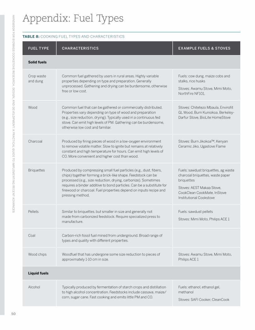
Appendix: Fuel Types
TABLE 8: COOKING FUEL TYPES AND CHARACTERISTICS
FUEL TYPE CHARACTERISTICS EXAMPLE FUELS & STOVES
Solid fuels
Crop waste and dung
Common fuel gathered by users in rural areas. Highly variable properties depending on type and preparation. Generally unprocessed. Gathering and drying can be burdensome, otherwise free or low cost.
Fuels: cow dung, maize cobs and stalks, rice husks
Stoves: Awamu Stove, Mimi Moto, NorthFire NF101,
Wood Common fuel that can be gathered or commercially distributed. Properties vary depending on type of wood and preparation (e.g., size reduction, drying). Typically used in a continuous fed stove. Can emit high levels of PM. Gathering can be burdensome, otherwise low cost and familiar.
Stoves: Chitetezo Mbaula, Envirofit GL Wood, Burn Kuniokoa, Berkeley-Darfur Stove, BioLite HomeStove
Charcoal Produced by firing pieces of wood in a low-oxygen environment to remove volatile matter. Slow to ignite but remains at relatively constant and high temperature for hours. Can emit high levels of CO. More convenient and higher cost than wood.
Stoves: Burn Jikokoa™, Kenyan Ceramic Jiko, Ugastove Flame
Briquettes Produced by compressing small fuel particles (e.g., dust, fibers, chips) together forming a brick-like shape. Feedstock can be processed (e.g., size reduction, drying, carbonize). Sometimes requires a binder additive to bond particles. Can be a substitute for firewood or charcoal. Fuel properties depend on inputs recipe and pressing method.
Fuels: sawdust briquettes, ag waste charcoal briquettes, waste paper briquettes
Stoves: AEST Makaa Stove, CookClean CookMate, InStove Institutional Cookstove
Pellets Similar to briquettes, but smaller in size and generally not made from carbonized feedstock. Require specialized press to manufacture.
Fuels: sawdust pellets
Stoves: Mimi Moto, Philips ACE 1
Coal Carbon-rich fossil fuel mined from underground. Broad range of types and quality with different properties.
Wood chips Woodfuel that has undergone some size reduction to pieces of approximately 1-10 cm in size.
Stoves: Awamu Stove, Mimi Moto, Philips ACE 1
Liquid fuels
Alcohol Typically produced by fermentation of starch crops and distillation to high alcohol concentration. Feedstocks include cassava, maize/corn, sugar cane. Fast cooking and emits little PM and CO.
Fuels: ethanol, ethanol gel, methanol
Stoves: SAFI Cooker, CleanCook
HA
ND
BO
OK
FOR
BIO
MA
SS
CO
OK
ST
OV
E R
ES
EA
RC
H, D
ES
IGN
, AN
D D
EV
ELO
PM
EN
T: A
PR
AC
TIC
AL G
UID
E T
O IM
PL
EM
EN
TIN
G R
EC
EN
T A
DV
AN
CE
S
50
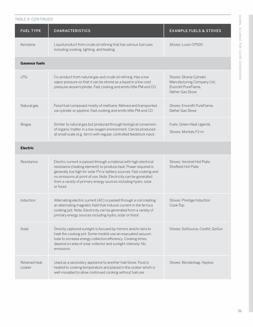
FUEL TYPE CHARACTERISTICS EXAMPLE FUELS & STOVES
Kerosene Liquid product from crude oil refining that has various fuel uses including cooking, lighting, and heating
Stoves: Luxor CP500
Gaseous fuels
LPG Co-product from natural gas and crude oil refining. Has a low vapor pressure so that it can be stored as a liquid in a low-cost pressure vessel/cylinder. Fast cooking and emits little PM and CO.
Stoves: Ghana Cylinder Manufacturing Company Ltd., Envirofit PureFlame, Delher Gas Stove
Natural gas Fossil fuel composed mostly of methane. Refined and transported via cylinder or pipeline. Fast cooking and emits little PM and CO.
Stoves: Envirofit PureFlame, Delher Gas Stove
Biogas Similar to natural gas but produced through biological conversion of organic matter in a low-oxygen environment. Can be produced at small scale (e.g. farm) with regular, controlled feedstock input.
Fuels: Green Heat Uganda
Stoves: Montals F2-m
Electric
Resistance Electric current is passed through a material with high electrical resistance (heating element) to produce heat. Power required is generally too high for solar PV or battery sources. Fast cooking and no emissions at point of use. Note: Electricity can be generated from a variety of primary energy sources including hydro, solar or fossil.
Stoves: Vonshef Hot Plate, Sheffield Hot Plate
Induction Alternating electric current (AC) is passed through a coil creating an alternating magnetic field that induces current in the ferrous cooking pot. Note: Electricity can be generated from a variety of primary energy sources including hydro, solar or fossil.
Stoves: Prestige Induction Cook-Top
Solar Directly captured sunlight is focused by mirrors and/or lens to heat the cooking pot. Some models use an evacuated vacuum tube to increase energy collection efficiency. Cooking times depend on area of solar collector and sunlight intensity. No emissions.
Stoves: SolSource, CooKit, GoSun
Retained heat cooker
Used as a secondary appliance to another fuel/stove. Food is heated to cooking temperature and placed in the cooker which is well-insulated to allow continued cooking without fuel use.
Stoves: Wonderbag, Haybox
TABLE 8: CONTINUED
GLO
BA
L AL
LIA
NC
E FO
R C
LE
AN
CO
OK
ST
OV
ES
51
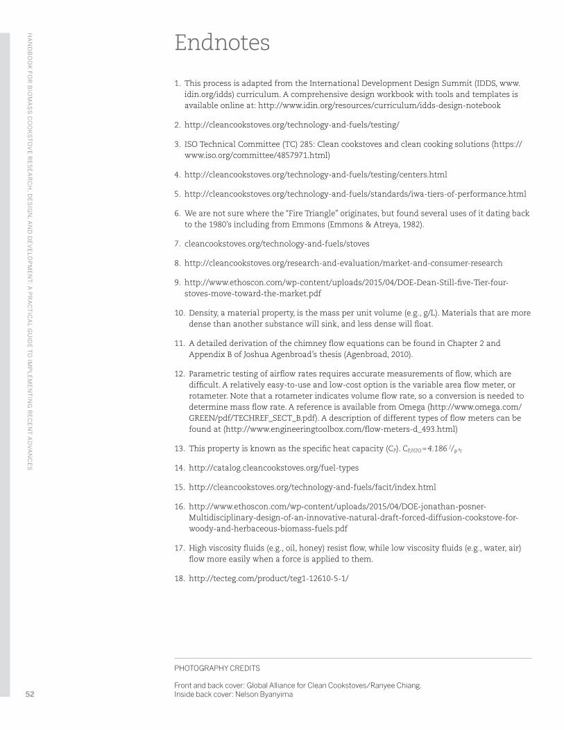
Endnotes
1. This process is adapted from the International Development Design Summit (IDDS, www.idin.org/idds) curriculum. A comprehensive design workbook with tools and templates is available online at: http://www.idin.org/resources/curriculum/idds-design-notebook
2. http://cleancookstoves.org/technology-and-fuels/testing/
3. ISO Technical Committee (TC) 285: Clean cookstoves and clean cooking solutions (https://www.iso.org/committee/4857971.html)
4. http://cleancookstoves.org/technology-and-fuels/testing/centers.html
5. http://cleancookstoves.org/technology-and-fuels/standards/iwa-tiers-of-performance.html
6. We are not sure where the “Fire Triangle” originates, but found several uses of it dating back to the 1980’s including from Emmons (Emmons & Atreya, 1982).
7. cleancookstoves.org/technology-and-fuels/stoves
8. http://cleancookstoves.org/research-and-evaluation/market-and-consumer-research
9. http://www.ethoscon.com/wp-content/uploads/2015/04/DOE-Dean-Still-five-Tier-four-stoves-move-toward-the-market.pdf
10. Density, a material property, is the mass per unit volume (e.g., g/L). Materials that are more dense than another substance will sink, and less dense will float.
11. A detailed derivation of the chimney flow equations can be found in Chapter 2 and Appendix B of Joshua Agenbroad’s thesis (Agenbroad, 2010).
12. Parametric testing of airflow rates requires accurate measurements of flow, which are difficult. A relatively easy-to-use and low-cost option is the variable area flow meter, or rotameter. Note that a rotameter indicates volume flow rate, so a conversion is needed to determine mass flow rate. A reference is available from Omega (http://www.omega.com/GREEN/pdf/TECHREF_SECT_B.pdf). A description of different types of flow meters can be found at (http://www.engineeringtoolbox.com/flow-meters-d_493.html)
13. This property is known as the specific heat capacity (CP). CP,H2O ≈ 4.186 J/g∙ºc
14. http://catalog.cleancookstoves.org/fuel-types
15. http://cleancookstoves.org/technology-and-fuels/facit/index.html
16. http://www.ethoscon.com/wp-content/uploads/2015/04/DOE-jonathan-posner-Multidisciplinary-design-of-an-innovative-natural-draft-forced-diffusion-cookstove-for-woody-and-herbaceous-biomass-fuels.pdf
17. High viscosity fluids (e.g., oil, honey) resist flow, while low viscosity fluids (e.g., water, air) flow more easily when a force is applied to them.
18. http://tecteg.com/product/teg1-12610-5-1/
PHOTOGRAPHY CREDITS
Front and back cover: Global Alliance for Clean Cookstoves/Ranyee Chiang. Inside back cover: Nelson Byanyima
HA
ND
BO
OK
FOR
BIO
MA
SS
CO
OK
ST
OV
E R
ES
EA
RC
H, D
ES
IGN
, AN
D D
EV
ELO
PM
EN
T: A
PR
AC
TIC
AL G
UID
E T
O IM
PL
EM
EN
TIN
G R
EC
EN
T A
DV
AN
CE
S
52
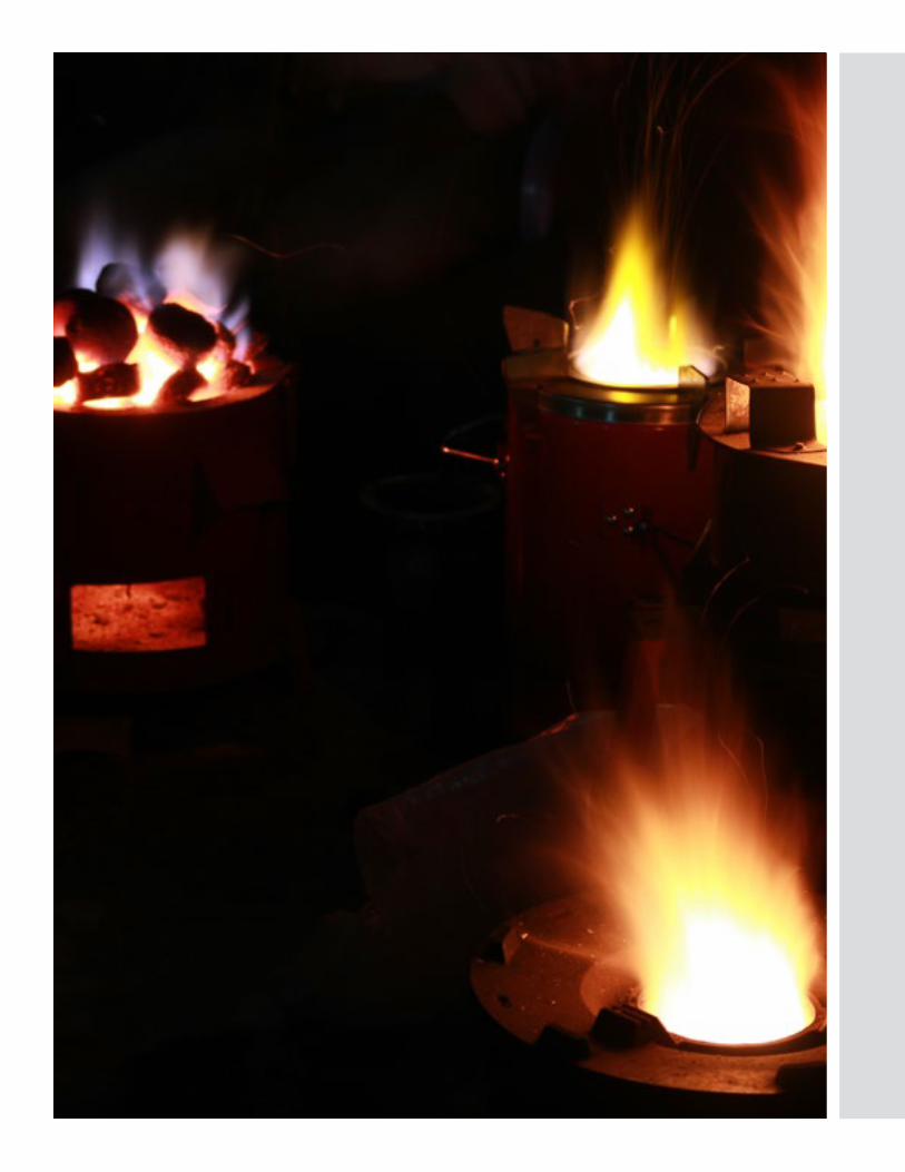

WWW.CLEANCOOKSTOVES.ORG