Embed Size (px)
Citation preview

Handbook and Troubleshooting Guide for
MW-S83 Model Rock Drills
Mid-Western, LLC
1495 East Pearce Boulevard
Wentzville, MO 63385
United States of America
Phone: +1 (636) 327-0545 Fax: +1 (636) 327-6848
www.mwdrill.com

This is a handbook of established practices and practical suggestions for
maintenance and repair of Mid-Western S83 pneumatic rock drills.
For customer assistance please call:
Phone: +1 (636) 327-0545
Fax: +1 (636) 327-6848
www.mwdrill.com
To find product breakdowns and parts diagrams, or to find an
authorized distributor in your area, please visit www.mwdrill.com
Limited Warranty
Subject to the terms and conditions hereinafter set forth, Mid-Western, LLC located at
1495 East Pearce Boulevard, Wentzville, MO 63385, USA (The Company) warrants
products and parts sold by it, insofar as they are of its own manufacture, against defects
of material and workmanship. Warranty applies under use and service in accordance
with The Company’s written instructions, recommendations, and ratings for installation,
operating, and maintaining/servicing of products for a usage period of three (3) months.
This warranty shall in no case extend beyond one (1) year from the date of shipment.
This warranty is limited to the repair or replacement, as the company may elect, of any
defective parts, regarding which, upon discovery of the defects, the purchaser has given
immediate written notice. Installation and transportation costs are not included. The
Company shall have the option of requiring the return of the defective material for
inspection, with transportation prepaid. The company does not warrant the
merchantability of its products and does not make any warranty, express or implied,
other than the warranty contained herein. The Company has not authorized anybody to
make any representation or warranty other than the warranty contained herein. The
use of any aftermarket replacement parts that are not genuine Mid-Western OEM parts,
voids any and all warranties.
Introduction
This handbook is intended for the use of service personnel whose job it is to operate
and repair Mid-Western S83 Jackleg, Sinker, and Stoper rock drills. Modern rock drills
are percussion machines that are manufactured with extremely close tolerances. These
drills are subjected to a great deal of hard service and abuse by those who operate
them. In spite of our best efforts to make a drill that will run forever, rock drills can and
do wear out and break down. We hope that the information provided in this handbook
will help with the task of maintaining Mid-Western rock drills and keep them operating
at their best.

MWS83 Jackleg Drill
The most dependable jackleg drill on the market! This
workhorse has been the industry leader for decades,
and for good reason. It’s hard-hitting and has fast
penetration rates with low maintenance costs. Careful
weight distribution and balance provide greater
operator efficiency with less fatigue. Available with
either standard telescopic feed legs or power
retractable feed legs in a number of lengths for plenty
of versatility.
MWS83 Sinker Drill
The power of the S83 jackleg in a sinking hammer. Great for
shaft sinking, quarry work, construction work, and utility work.
It comes equipped with heavy-duty neoprene rubber grips for
added comfort.
MWRB83 Stoper Drill
A powerful and robust stoper drill that’s great for overhead
applications. This unit has plenty of power and torque to
drive roof bolts and fasten roof bolt nuts. Available with
two leg options for better access in tight spaces.

Guidelines for Operators
NEVER operate a drill that you feel is unsafe to use. Tag the drill and set it aside
for repair.
NEVER operate a drill if you notice lacerations or abrasions to the air hose. The
hose could break and cause injury when under pressure. Be sure to have
whipchecks installed on the air hoses at any connection point to reduce
the risk of injury in the event the hose breaks.
NEVER pound on stuck drill steel. It accomplishes nothing and you may damage
the drill, the steel, or the bit.
NEVER retract the steel while drill is at full throttle. This can cause damage to the
piston, steel puller, and side rods.
NEVER strike the drill with tools or any other object. You may dent the cylinder or
cause other damage.
NEVER try to turn the drill in the hole when the steel is stuck. Pawls will break if
the drill is turned in the opposite direction from normal rotation.
NEVER try to repair the drill on the job. Take the drill to a clean repair shop.
NEVER drag a drill along the ground. This will allow dirt and foreign matter to
enter the drill through the exhaust ports and other openings. The smallest
particles of debris in a drill can cause malfunction and possible drill failure.
NEVER ride the feed leg of the drill as this could result in serious injury. The feed
leg is designed to advance the drill so operate it carefully.
NEVER use damaged drill steel. Use of a damaged drill steel can cause damage to
the drill piston. A damaged drill piston will subsequently damage any new
drill rod that is used with that piston.

Guidelines for Operators
ALWAYS wear approved personal protective equipment including safety glasses,
steel-toed boots, gloves, respirators, hard hats, and ear protection. You
should always wear both ear plugs and ear muffs for added protection.
Rock drills are percussive tools with high decibel emissions.
ALWAYS blowout air supply hoses and flush out water hoses before connecting
them to the drill. This will rid the hoses of dirt, debris, and rust.
ALWAYS be sure the drill is well lubricated. Adjust the line oiler so the steel shank
always shows oil film yet does not cause fogging. Lack of oil can decrease
the longevity of the drill and parts.
ALWAYS keep side rods tight and at equal tension. Side rod nuts should be
tightened to a minimum of 110 FT./LB.
ALWAYS check to ensure all nuts are tight before operating a drill. Make sure that
nothing has vibrated loose and all connections and nuts are secure.
ALWAYS make sure to wear proper clothing when operating a drill. Do not wear
loose fitting articles as they have the potential to get caught up in the
rotation of the drill steel. Make sure to tie back any loose hair or any
other particles that could become entangled.
ALWAYS keep drill aligned with drill steel and hole. Hold the drill firmly and apply
even pressure with both hands. Use the maximum feed leg pressure that
you can without stalling the drill. Good alignment and pressure will
reduce wear and prolong the life of drill parts, steel, and bits.
ALWAYS store drills in an upright position when not being used. Cover all exhaust
ports and openings to keep dust and debris from collecting in the drill.

Rock Drill Options
Item Number Drill Type Steel Size Leg Model
MWS83FA Feed Leg Drill 7/8" (22 mm) FL7
MWS83FB Feed Leg Drill 1" (25 mm) FL7
MWS83FC Feed Leg Drill 7/8" (22 mm) TUL2B
MWS83FD Feed Leg Drill 1" (25 mm) TUL2B
MWS83DA Sinker Drill (Dry) 7/8" (22 mm) N/A
MWS83DB Sinker Drill (Dry) 1" (25 mm) N/A
MWS83WA Sinker Drill (Wet) 7/8" (22 mm) N/A
MWS83WB Sinker Drill (Wet) 1" (25 mm) N/A
MWRB83A Stoper Drill 7/8" (22 mm) RB83TUL
MWRB83B Stoper Drill 1" (25 mm) RB83TUL
MWS83 Rock Drill Specifications
US Metric
Piston Diameter 3'' 76 mm
Length of Stroke 2.5" 64 mm
Overall Length 27-1/4" 688 mm
Total Weight 72 lbs. 32.4 kg
Air Hose Size 1" 25 mm
Water Hose Size 1/2" 13 mm
Chuck Size 7/8" or 1" x 4 1/4" 22 mm or 25 mm x 108 mm
Pressure (PSI) Percussion Speed (Impacts per Minute) Energy Per Blow (LB/FT)
80 2,256 59.6
90 2,302 69.2
100 2,418 84.8

Feed Leg Options
TUL2B Model (Telescopic)
Item Number Length of Feed Travel Collapsed Length Extended Length
TUL2B24 24" (61 cm) 29-3/8" (75 cm) 53-3/8" (136 cm)
TUL2B36 36" (91 cm) 35-3/8" (90 cm) 71-3/8" (181 cm)
TUL2B48 48" (122 cm) 41-3/8" (110 cm) 89-3/8" (227 cm)
TUL2B60 60" (152 cm) 47-3/8" (120 cm) 107-3/8" (273 cm)
TUL2B72 72" (183 cm) 53-3/8" (136 cm) 125-3/8" (318 cm)
FL7 Model (Power Retractable)
Item Number Length of Feed Travel Collapsed Length Extended Length
FL736 36" (91 cm) 54" (137 cm) 90" (229 cm)
FL742 42" (107 cm) 60" (152 cm) 102" (259 cm)
FL754 54" (137 cm) 72" (183 cm) 126" (320 cm)
RB83TUL (Stoper Leg)
Item Number Length of Feed Travel Collapsed Length Extended Length
RB83TUL24 24" (61 cm) 27-1/4" (69 cm) 55" (140 cm)
RB83TUL36 36" (91 cm) 33-1/4" (84 cm) 67" ( 170 cm)

Typical Properties of Rock Drill Lubricants
Viscosity for Air Temperatures
ISO Viscosity
Grade
Minimum Flash Point
Pour Point Pin Wear Test Film Strength
(PSI)
Steam Emulsion Number
Below 20F (7C) 32 360F (182C) -55F (-48C) 300,000 1,200+
20F to 40F (-7C to 4C) 68 405F (207C) -30F (-34C) 300,000 1,200+
40F to 80F (4C to 27C) 100 420F (216C) -10F (-23C) 300,000 1,200+
80F to 110F (27C to 43C) 150 445F (229C) -5F (-21C) 300,000 1,200+
Above 110F (43C) 220 470F (243C) 5F (-15C) 300,000 1,200+
Rock drill oil used in air-line oilers should adhere to the metallic surfaces under
conditions which exist in a rock drill.
Viscosity is a measure of the oil’s resistance to change due to temperature
fluctuations. The higher the number, the less the viscosity changes.
Flash point is the minimum temperature at which sufficient liquid is vaporized to
create a mixture of fuel and air that will burn if ignited, and is only of an instant’s
duration.
Pour point is the lowest temperature to which an oil can be chilled and still be
poured from a container.
The film strength and lubricity is a measure of the load an oil will sustain between
two metal surfaces without scoring.
The steam emulsion number is a measure of the life of an emulsion developed
between volumes of oil and water under certain conditions. A high number
(1,200+) indicates good lubrication in the presence of water and also prevents
foaming in the air-line oiler.

Air Pressure & Consumption
Proper air supply is crucial! S83 drills will run with optimal performance when running
between 90-100 PSI of pressure. This will usually require at least 185 CFM of volume to
support the pressure required. Please keep in mind that there are several factors that
can affect air pressure such as altitude, length of air hose, leakage in air lines, etc. The
PSI reading should be taken at the drill itself to ensure proper air pressure.
Low air pressure will keep the drill from operating as it should which is wasteful and
results in lost time, production, and cost.
High air pressure will provide faster drilling speeds but it can also increase the strain on
critical drill parts. Operating between 90-100 PSI will prolong the life of internal parts.
Lubrication
Along with air pressure, adequate lubrication is crucial in proper drill use and
maintenance. S83 rock drills produce a lot of heat. If the drill runs dry, even for a small
amount of time, it can cause fractures in parts that lead to part failures.
Operators must ensure that drills are getting proper lubrication or else the drills can be
severely damaged.
Before running a drill, always pour a few ounces of rock drill oil directly in the air
connection of the drill before attaching the air hose.
The best way to keep a drill lubricated is to use an air line lubricator.
• The use of an air line lubricator will ensure that oil is being dispersed to the drill
at a constant flow.
• A separate lubricator should be used for each drill in operation.
• The lubricator’s flow is adjustable by removing the filler cap. The drill steel shank
should have a light film of oil present when drilling and the lubricator’s flow
should be adjusted accordingly.
• Always check the lubricator every two hours to make sure there is enough oil in
the lubricator

• The lubricator should be positioned in the air line no further than 10 feet from
the drill. Placing the lubricator further than 10 feet will keep oil from reaching
the drill.
Refer to the “Typical Properties of Rock Drill Lubricants” chart in this handbook for more
information regarding proper rock drill oil to use.
Checklist for Operating a Drill
• Make sure to wear all PPE including safety glasses, steel-toed boots, hard hat,
double ear protection, gloves, and respirator.
• Ensure no loose clothing is worn by the operator and loose hair is tied back.
• Blow all air and water lines out to clear any blockage or debris.
• Check the air line lubricator and make sure it’s full and adjusted properly.
• Ensure air line lubricator is in the air line no further than 10 feet from the drill.
• Make sure all air and water hose fittings are tight and secure.
• Make sure the feed leg connection is tight and secure.
• Make sure both side rods and both steel puller nuts are tight and secure.
• Prime the drill directly with 1-2 ounces of rock drill oil.
• Make sure whip checks are installed on the air and water lines.
• Connect the air and water hoses the drill.
• Make sure the air pressure at the drill is between 90-100 PSI.
• Make sure the leg controls and drill throttle are in the closed position. The leg
control will be turned all the way towards the operator in the closed position.
The drill throttle handle will be vertical in the closed position. Even with the drill
throttle closed, it is normal to hear some air blowing and bypassing in the drill.
• Inspect the steel and bit to make sure they are in good condition.

• Insert the drill steel into the drill and close the steel puller.
• Turn on the water and air flow to the drill.
• Get your body into a stable drilling position.
• Blow air and oil to the front of the drill by pulling backwards on the throttle
handle. The drill throttle will be in the vertical position when it is closed. Pulling
backwards (towards the operator) will allow only air and oil to pass to the front
of the drill which lubricates the drill.
• Slowly move the throttle handle forward to start the drill. The drill throttle will
be in the vertical position when it is closed. Moving the drill throttle forward
(away from the operator) will increase the throttle speed and rotation.
• Start to collar the hole at a slow drilling speed and make sure the bit has
penetrated into the rock about 2”.
• Once the hole is collared, increase the throttle.
• Use the feed control knob on the control handle to adjust the pressure of the
feed leg. You want to keep steady leg pressure to keep the bit in constant
contact against the rock face. Too little pressure will cause the bit to bounce, but
too much pressure can keep the bit from rotating.
• Continue to drill out the hole until the steel puller is 2” away from the rock face.
• Decrease the drill throttle and pull the steel out of the hole. Do NOT run the drill
at full throttle when pulling the steel out.
• Protect and store the drill when not in use. Never lay a drill on the ground where
debris can enter through the exhaust ports or fronthead (chuck end). Always
protect the drill when blasting.
Safety Instructions
It is important that every operator be familiar with and adheres to these safety warnings
and instructions. Failure to do so can result in serious injury or even death. Always read
and review these instructions before operating any Mid-Western rock drill. These
warning should be posted in a visible area and be distributed to all operators that will be
around Mid-Western rock drills.
NEVER operate a Mid-Western rock drill if you are under the influence of drugs, alcohol,
or medication.
Only qualified and trained individuals should operate Mid-Western rock drills.
Operators must wear personal protective equipment (PPE) when operating or when
near a Mid-Western rock drill. This includes, but is not limited to, approved hard hat,
approved double hearing protection, eye protection, protective gloves, long sleeve
coverall or approved shirt and pants, steel toed protective boots, and respiratory
equipment.
Be aware the Mid-Western rock drills operate on compressed air. Compressed air can
be dangerous. Air lines have the potential to crack, break, or explode. Always use
whipchecks or approved safety restraints and pins. Always check to make sure air
connections are tight before starting or operating a drill. Never disconnect an air
connection while the air hose while it is under pressure. Air hoses and water hoses can
also present a tripping hazard. Always be mindful of the location of hoses and avoid
stepping on or near the hoses.
Mid-Western rock drills can have pinch points, especially when equipped with feed legs
or pusher legs. Never place your hands, fingers, or any other extremities between the
drill and feed leg. The drill can pivot back onto the leg or the swivel assembly (the piece
that connects the drill to the leg) and cause injury.
Rock drills can produce high decibel levels of noise. ALWAYS wear double ear protection
that includes ear plugs in addition to over-the-ear muffs. Mufflers can also be installed
on Mid-Western rock drills to further reduce decibel levels.
Rock drills can produce dust and fumes through the drilling process. Exposure to dust
can cause illness and disease of the lungs, including silicosis. Always drill with water
when available. ALWAYS wear proper approved respirators.

Safety Instructions
Rock drills produce vibration while being operated. Repeated overexposure to vibration
can cause injuries or disorders to hands, fingers, arms, shoulders, nerves, and more.
These injuries sometimes develop over years of use. It is important for operators to
stop operation if they notice numbness, soreness, discomfort, burning sensations,
weakened grip strength, tingling, or any other condition that seems out of the ordinary.
To reduce the risk of injury, do not operate Mid-Western rock drills for extended
periods of time. Operators should use light grips when working with machines to
reduce the amount of vibration transfer from machine to person.
Rock drills can be heavy. Do not strain to lift a machine. Always ask for assistance. If
the rock drill is equipped with a feed leg/pusher leg, the weight of the machine can be
top-heavy. Make sure to maintain good balance with the machine when operating.
Keep your feet stable and balance your body weight. Improper balance or improper
operation can cause the machine to tip and potentially fall on the operator. This
crushing hazard and cause serious injury or even death.
Mid-Western rock drills work with hexagonal drill steels/rods. These steels/rods are
held in place by the steel puller. ALWAYS make sure the steel puller is in the closed
position before operating a drill. Failure to do so can result in the drill steel/rod
becoming a projectile that can cause serious injury or even death.
Mid-Western rock drills should never be modified. Modification of a machine can cause
serious injury or even death. Any modification voids any and all warranties.
ALWAYS inspect all equipment before use or operation. Make sure all connections and
nuts are tight and secure. Make sure the throttle for the drill and the throttle for the
feed leg/pusher leg are in the “OFF” position. Failure to do this can result in a
premature start and can cause injury or even death.

Troubleshooting Guide
Problem: The drill will not start.
Possible cause: The air line or hose is blocked.
Solution: Blow out the lines and clear blockage.
Possible cause: The piston is stuck and air is blowing by exhaust ports.
Solution: There is possibly a damaged S83F1T Cylinder or broken 1S83F9 Piston.
Inspect the parts for damage.
Possible cause: The S83F Valve Chest Assembly could be stuck.
Solution: Move the throttle handle back and forth from the blow position to
forward throttle to try and free the valve. Oil can sometimes collect in the valve
when the drill sits and causes it to become stuck.
Possible cause: The piston is stuck and there is no air blowing.
Solution: The rotation could be jammed. Check the 1S83F9 Piston, S63F7N
Chuck Nut, S83F2628 Rifle Bar, S83F2528 Rifle Nut, R9111A Pawls, and S5511C
Springs to make sure they are in good working condition. Replace worn parts.
Possible cause: High pressure water is backing up into the drill.
Solution: Check D83N40X Water Gland Assembly and S63F27BX Water Tube
Assembly to make sure they are in good working condition.
Possible cause: The muffler is frozen and the exhaust ports are iced up.
Solution: Install moisture trap in the air line. Check S63F27B Water Tube to
make sure it's not broken.
Possible cause: S53F1L Liner is tight or damaged.
Solution: Hone or ream the part to proper size. Replace the part if it is damaged.

Problem: The drill operates erratic or sluggish.
Possible cause: The rock drill oil may be too heavy for temperature.
Solution: Check and change the oil grade.
Possible cause: There is not enough oil reaching the drill.
Solution: Adjust the air line lubricator and set properly. The air line lubricator
should be no further than 10 feet from the drill.
Possible cause: The drill is heating up.
Solution: Check the air line lubricator. Fill or clean as necessary.
Possible cause: There is dirt or debris in the drill.
Solution: Disassemble the drill (in a clean workshop, not on-site) and check for
damage. Inspect and clean drill parts as necessary. Always protect the drill when
blasting and storing.
Possible cause: The S83F Valve Chest Assembly is sticking while operating.
Solution: Clean the valve and check for burrs or nicks.
Problem: The drill is lacking power but sounds good.
Possible cause: There are broken or damaged parts, possibly R9111A Pawls and
S5511C Springs.
Solution: Make sure all parts are clean, undamaged, and are operating freely.
Possible cause: The drill steel has a shank that is too short or too long.
Solution: Check the drill steel and make sure the shank measures 4-1/4” in
length.
Possible cause: There is a worn or broken piston.
Solution: Replace 1S83F9 Piston.
Possible cause: There is a plugged air hose or air leak.
Solution: Ensure the hoses don’t have damage and blow out the lines.
Problem: The drill is lacking power but sounds good.
Possible cause: There is low air pressure.
Solution: Check the air lines and valves. Make sure the drill has optimal drilling
air pressure between 90 and 100 PSI.
Possible cause: There is a loss of front end cushion.
Solution: The 1S83F9 Piston or the S53F1L Liner is worn. Check for wear and
replace as needed.
Possible cause: The 1041277 Chuck Liner or S58F7TLF Chuck Liner is worn.
Solution: Use a chuck gauge to check for wear and replace as needed.
Possible cause: The 1040906 Chuck End is damaged.
Solution: Repair or replace as needed.
Possible cause: There is a lack of oil which causes the front end to be warm.
Solution: Check the air line lubricator and adjust as necessary.
Problem: There is slow rotation or no rotation.
Possible cause: The drill steel is bent.
Solution: Inspect the drill steel and change if necessary.
Possible cause: There are damaged rotation parts.
Solution: Check the 1S83F9 Piston, S63F7N Chuck Nut, S83F2628 Rifle Bar,
S83F2528 Rifle Nut, R9111A Pawls, S5511C Springs, and S83F3335 Ratchet Ring to
make sure they are in good working condition. Replace worn parts as necessary.
Possible cause: There is damage to the drill because of lack of lubrication.
Solution: Check the drill for damage and oil. Adjust air line lubricator
accordingly.
Possible cause: The machine was not assembled properly.
Solution: Check for proper assembly and make sure side rods are tightened
correctly. Tighten them alternately and evenly to 110 FT/LB. of torque.
Problem: Slow drilling speed.
Possible cause: There is low air pressure.
Solution: Check the air lines and valves. Make sure the drill has optimal drilling
air pressure between 90 and 100 PSI.
Possible cause: The airline or screen is plugged.
Solution: Blow out the lines and clear blockage. Make sure hoses are not
damaged.
Possible cause: There is low water pressure or volume.
Solution: Check the S48F13X Water Valve, S63F27B Water Tube, and D83N40X
Water Gland Assembly for blockages or damage. Check the water lines for
blockage or damage. There should be 60-70 PSI of water pressure. Also check
the center hole of the drill steel and make sure it's not blocked.
Possible cause: There is improper alignment in the hole.
Solution: Always make sure the drill steel is centered in the borehole.
Problem: The drill is overheating.
Possible cause: The drill is lacking oil.
Solution: Check the air line lubricator to ensure it’s working properly and is full.
Possible cause: Improper oil is being used.
Solution: Check to make sure the correct weight rock drill oil is being used.
Motor oil will not work and can damage the drill. Only use rock drill oil.
Possible cause: There is improper push on the feed leg causing the drill to
bounce.
Solution: Adjust the feed pressure of the leg. Check to make sure the cups and
seals in the leg are not leaking.

Problem: Drill cuttings are not being removed.
Possible cause: There is low water pressure or volume.
Solution: Check the S48F13X Water Valve, S63F27B Water Tube, and D83N40X
Water Gland Assembly for blockages or damage. Check the water lines for
blockage or damage. There should be 60-70 PSI of water pressure. Also check
the center hole of the drill steel and make sure it's not blocked.
Possible cause: There is high water pressure or volume.
Solution: Check the water lines. The water pressure should be 20 to 30 PSI lower
than the air pressure.
Problem: Water tubes are being cut off or are splitting.
Possible cause: The drill steel has plugged, worn, or mushroomed shanks.
Solution: Inspect the drill steel for damage. Replace or refurbish the drill steel if
necessary.
Possible cause: The 1041277 Chuck Liner or S58F7TLF Chuck Liner is worn.
Solution: Use a chuck gauge to check for wear and replace as needed.
Excessively worn chuck liners cause misalignment and will damage water tubes.
Possible cause: The center hole of the 1S83F9 Piston is damaged.
Solution: Chamfer the center hole of the piston to ensure it is smooth with no
sharp edges that can chip and peen the water tube.
Problem: The muffler is freezing up.
Possible cause: There is excessive moisture in the air lines.
Solution: Drain the air line and install moisture traps.
Possible cause: The water tube is broken.
Solution: Replace S63F27B Water Tube and 729B Water Tube Seal.

Problem: The drill is fogging.
Possible cause: The water tube is broken.
Solution: Replace S63F27B Water Tube and 729B Water Tube Seal.
Possible cause: Water is leaking around the water tube.
Solution: Replace 729B Water Tube Seal
Possible cause: There is excessive moisture in the air.
Solution: Drain the air line and install moisture traps.
Possible cause: Too much oil is reaching the drill.
Solution: Adjust the air line lubricator accordingly.
Problem: The piston is chipped or broken.
Possible cause: The drill steel is worn.
Solution: Check drill steel shanks and reface all crowned, worn, beveled, or
chipped steel.
Possible cause: The piston was poorly refaced.
Solution: Reface the 1S83F9 Piston so that the axis of the piston is exactly at right
angles to the striking face.
Possible cause: The piston is damaged.
Solution: Check the 1S83F9 Piston for visible scuff or scoring. Replace the piston
if it is damaged.
Possible cause: The 1041277 Chuck Liner or S58F7TLF Chuck Liner is worn.
Solution: Use a chuck gauge to check for wear and replace as needed.
Problem: Bronze cuttings are getting into the drill.
Possible cause: There is a lack of oil.
Solution: Adjust the air line lubricator accordingly.
Possible cause: The rifle bar is rough or damaged.
Solution: Replace the S83F2628 Rifle Bar or use a fine grindstone to smooth out
parts.
Possible cause: The piston is rough or damaged.
Solution: Replace the 1S83F9 Piston or use a fine grindstone to smooth out parts.
Problem: Parts are wearing out excessively fast.
Possible cause: There is improper lubrication.
Solution: Replace all damaged parts. Check the grade of rock drill oil and adjust
the air line lubricator. Make sure the lubricator is working properly.
Possible cause: There is dirt in the drill.
Solution: Disassemble the drill (in a clean workshop, not on-site) and check for
damage. Inspect and clean all parts as necessary. Always protect the drill when
blasting and storing. Even the smallest pieces of dirt or debris can damage or
ruin a rock drill. It’s extremely important to keep the drill clean.

Individual Part Troubleshooting Guide
1S83F9 Piston and S83F2628 Rifle Bar
Both the piston (hammer) and rifle bar should be replaced when the flutes show
signs of sharpening and splines are worn 1/4 to 1/3 of original size. If you notice
small cracking or scoring on the piston or rifle bar it could be from lack of oil.
Check the air line lubricator and make sure it is set properly.
The piston O.D. measures 2.998”. A clean, dry piston can be dropped into a
cylinder of a drill and fall on a cushion of air. If it does not, check to see why
there is no air cushion. The S53F1L Liner, 1S83F9 Piston, or S83F1T Cylinder
could be worn too much. If the piston head is measuring 2.996” it should be
replaced.
The S53F1L Liner should be replaced if it measures 1.570” or larger in the inside
diameter.
Rifle bars also may need to be replaced if there is excessive play in the pawl area
where the pawls and springs are set.
S83F2528 Rifle Nuts and S63F7N Chuck Nuts
Rifle nuts and chuck nuts should be replaced when 1/4 to 1/3 of the splines are
worn. Always lubricate the threads and splines on the nuts when replacing. Rifle
nuts and chuck nuts have a left-hand thread.
The chuck nut should be fairly tight to keep the piston in proper alignment with
the drill steel.
S83F3335 and S83F33334 Ratchet Rings
Ratchet rings need to be replaced when the teeth show excessive rounding. The
teeth should be rigid and able to engage the pawls in place. When they are
excessively worn or chipped the drill can lose rotation.
Jackleg ratchet rings have 35 teeth (S83F3335) and Stoper ratchet rings have 34
teeth (RB833334).

R9111A Pawls and S5511C Pawl Springs
Pawls are a high wear item and should be replaced when drill rotation starts to
slow or stop. If you see visible roundness of the pawls it is time to change them.
You should always replace pawl springs when you replace or flip the pawls.
The pawls are reversible and can be flipped over and used a second time before
replacement.
S58F7DA Chuck Driver and 1041277 Chuck Liner and S58F7TLF Chuck Liner
The best way to check to see if a chuck liner is worn is to use a chuck gauge. The
chuck gauge is a go/no-go gauge that will insert into the chuck liner when it is
worn too far. If the gauge inserts more than halfway down the part needs to be
replaced. The chuck liners are NOT reversible. Do not flip a chuck liner over and
use the other side. This can cause misalignment of the drill steel and damage the
drill. Chuck gauges are available from Mid-Western.
When several chuck liners have been pressed into the same chuck driver it can
wear the chuck driver from overexpansion. This can cause the liner to slip and
lose rotation. It can also cause the liner to be pressed in slightly off-center,
causing misalignment with the drill steel and piston. The chuck driver should be
replaced in either of these instances. Always use a press to install a chuck liner
into a chuck driver, never use a hammer.
S53F36A Steel Puller and S53F36B Steel Puller
Steel pullers are designed to help pull the drill steel out of the hole when finished
drilling. DO NOT operate a drill at full throttle when pulling steels. This can
damage the steel puller by smashing the ends of it. This can result in breakage of
the steel puller, damage to the trunnion, damage to the trunnion hole on the
chuck end, or even breaking of side rods.
If you notice the ends of steel pullers have a mushroom look to them, the
operator is probably using excessive throttle when pulling steel out.

S83F112ABXB Control Handle Assembly
The handle assembly contains your feed leg controls. This is a precision
machined part with very close tolerances. The handle sometimes can leak air.
There are two ORP116A O-Rings located under the feed control knob. Those can
crack or become damaged over time.
You can also have a faulty S83F116C Valve that will allow air to escape the
handle. If drills are mishandled or dropped, the handle can become damaged
and bend slightly. This can cause air to leak since it’s no longer sealed off
properly.
S83F Valve Chest Assembly
The valve chest assembly is the life behind the drill. If your drill will not start,
check the valve chest first. There are three components of the assembly
including the S83F15 Valve Chest, the S83F15B Valve Plug, and the S83F16
Automatic Valve. The automatic valve moves back in forth in the assembly and
fires the piston back and forth in the drill. The automatic valve must move freely
(but still maintain an air seal) in order for the drill to operate. The automatic
valve can become stuck on occasion, especially if the drill has been sitting for a
period of time and oil has collected in the valve chest assembly. You can try to
loosen the valve by reversing the drill throttle to blow air and then moving the
throttle back forward. If the automatic valve has a sloppy fit it should be
replaced.
S83F3 Side Rods
Side rods should be replaced when worn or broken. Always assemble a drill with
either two new or two used side rods. Never use a new and used side rod on the
same drill.
They should be torqued to 110 ft./lbs. If you are constantly breaking side rods
they could be too tight or your drill has lost its front end air cushion and the
piston is striking the cylinder bushing too hard.

S48F13X Water Connection Assembly and RB83147X Air Connection Assembly
Air and water connections should not wear out under normal working conditions.
These connections are usually damaged when the drill is mishandled or dropped.
They can bend or break, causing air or water leakage.
The water connection does have a screen in it. If water flow becomes restricted
check to make sure there is no debris in the screen preventing water from
reaching the drill.
FL990X Swivel Assembly and 1FL7310X Swivel Assembly
The swivel assemblies can become faulty and leak air. Normally this is due to the
o-rings in the swivel wearing out. Replace any dry, cracked, or broken o-rings.
If the drill has been dropped the swivel piston can also be bent which allows air
to escape.
Over time the cones will show wear and need to be replaced. The springs will
lose tension over time as well and need to be replaced. Inspect swivel assembly
to make sure everything is in working order.
TUL2B Feed Legs, FL7 Feed Legs, and RB83TUL Stoper Feed Legs
Feed legs can lose pressure when the cups and seals have started to wear. They
will become very flexible and in some cases will start to crack or break. Seals
should be checked often and replaced as necessary. Worn seals can cause the leg
to bounce or hop around or not hold pressure all together.
You should also check the center feed piston of the leg for signs of wear. This
part will wear out and it should be changed once visible signs of damage or
pitting is visible. A poorly worn feed piston will reduce the life of the cups and
seals.
Be careful not to drop or damage a feed leg. A bent tube will not work properly.
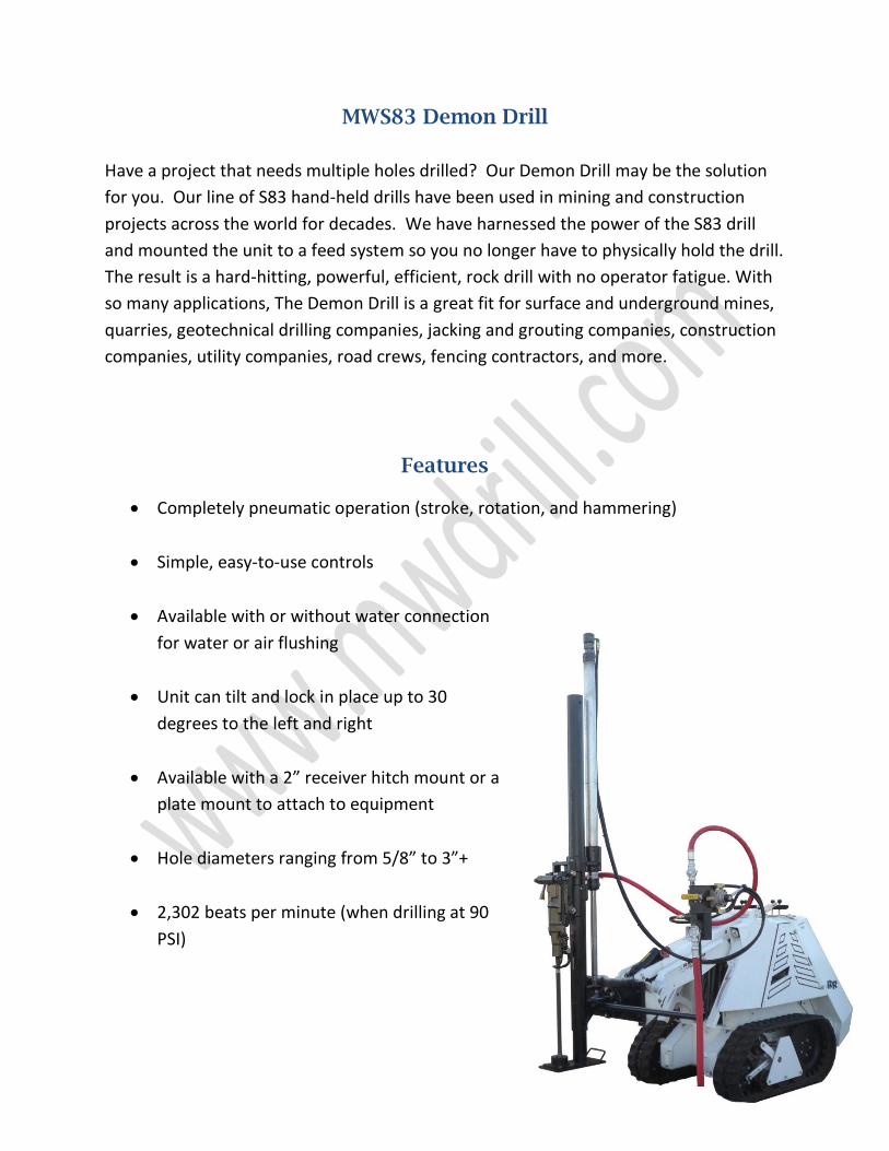
MWS83 Demon Drill
Have a project that needs multiple holes drilled? Our Demon Drill may be the solution
for you. Our line of S83 hand-held drills have been used in mining and construction
projects across the world for decades. We have harnessed the power of the S83 drill
and mounted the unit to a feed system so you no longer have to physically hold the drill.
The result is a hard-hitting, powerful, efficient, rock drill with no operator fatigue. With
so many applications, The Demon Drill is a great fit for surface and underground mines,
quarries, geotechnical drilling companies, jacking and grouting companies, construction
companies, utility companies, road crews, fencing contractors, and more.
Features
Completely pneumatic operation (stroke, rotation, and hammering)
Simple, easy-to-use controls
Available with or without water connection
for water or air flushing
Unit can tilt and lock in place up to 30
degrees to the left and right
Available with a 2” receiver hitch mount or a
plate mount to attach to equipment
Hole diameters ranging from 5/8” to 3”+
2,302 beats per minute (when drilling at 90
PSI)
For customer assistance please call:
Phone: +1 (636) 327-0545
Fax: +1 (636) 327-6848
www.mwdrill.com