Embed Size (px)
Citation preview
.
HANDBOOK ABOUT INTERPRETATION OF EN 13201
AND ROOM FOR IMPLEMENTATION OF DYNAMIC
LIGTHING
Version 1
07-2018

Page 1
1. Introduction Adaptive road lighting is defined as temporal controlled changes in luminance or illuminance in relation to traffic volume and/or traffic composition, time, or other influencing parameters of the surrounding envi-ronment. Dynamic road lighting is adaptive lighting, i.e. it is being provided where and when it is needed depending on different variable conditions, such as travelling speed, traffic volume and/or composition, ambient luminances, weathers and other exterior factors in a way that it reduces light pollution as well as energy consumption; beyond that it recognizes varying human and social needs, such as aesthetics or feel-ing of safety and security. The application of adaptive / dynamic road lighting is recommended as a possi-bility to reduce energy consumption, light pollution, and CO2-emission while keeping road safety and secu-rity at an appropriate level.
According to the European Technical Report CEN/TR 13201-1:2014 “Road lighting - Part 1: Guidelines on selection of lighting classes” [1] the rated (normal) road lighting class is defined as the class with the maximum value of luminance or illuminance at any period of operation. In the European Standard EN 13201-2:2015 “Road lighting - Part 2: Performance requirements” [2] a road lighting class is defined by a set of photometric requirements aiming at the visual needs of certain road users in certain types of road areas under specified environmental conditions. However, the application of the selected class may not be justified throughout the hours of darkness due to changing conditions. Temporal changes in the parame-ters under consideration could allow or may require an adaptation of the rated (normal) lighting level.
The use of adaptive / dynamic lighting can provide significant reduction in energy consumption, compared with operating the rated (normal) lighting class throughout the hours of darkness. In the European Stan-dard EN 13201-2:2015 “Road lighting - Part 5: Energy performance indicators” [3] methods are described which could be used to compare the energy performance of different road lighting solutions and technolo-gies for a given installation. In addition the knowledge and use of the (accumulated) ‘utilance road light-ing’ can serve as a tool for the pre-selection of adequate luminaires and the calculation of the installation luminous efficiency. This is described in the European Standard EN 13032-5:2018 “Light and lighting - Measurement and presentation of photometric data of lamps and luminaires - Part 5: Presentation of data for luminaires used for road lighting” [4).
Based on the beforehand mentioned European documents [1] [2] [3] [4] the applicability of adaptive / dynamic lighting to different road lighting situation will be discussed in view of safety and security of road users, energy efficiency, and social needs. The associated European Standards EN 13201-3:2015 “Road lighting - Part 3: Calculation of performance” [5] and EN 13201-4:2015 “Road lighting - Part 4: Methods of measuring lighting performance” [6] will be taken into account only insofar as a ranking of different road lighting solution could be affected seriously by inappropriate calculations and/or measure-ments.
2. The Purpose of Road Lighting According to the publication of the International Commission on Illumination CIE 115:2010 “Lighting of roads for motor and pedestrian traffic” [7] there are three main purposes of road lighting:
a) To provide visual conditions so that all road users can perform the necessary driving tasks and can pro-ceed safely,
b) To allow pedestrians to see hazards, to orientate themselves, to recognize other pedestrian’s face, and to give them an adequate sense of security,
Page 2
c) To improve the appearance of the environment particularly during the hours of darkness, e.g. to in-crease the readability of an urban area.
In the lighting of individual roads or public spaces the relative importance of these items needs to be evaluated, since the needs of motorists, cyclists and pedestrians differ. In all cases road lighting installa-tions should meet the relevant lighting requirements and should not compromise the visual aspects simply to reduce energy consumption.
2.1. Road Lighting for Motorized Traffic
The purpose of road lighting in general is to provide visual cues and to reveal obstacles, so that a safe vehicular operation is possible. Vehicle headlights and traffic safety devices, like road surface markings, delineators, and/or signs, assist the motorist in providing guidance. Fixed road lighting provides not only illumination on the road, but also on the nearby surroundings revealing extraneous objects and is opening up the field of view. This is of particular importance in areas of high visual complexity where there may be different types of road users (motorists, cyclists, pedestrians, slow moving vehicles) present at the same time [7].
2.2. Road Lighting for Pedestrians
The lighting of residential areas is mainly provided to give safe passage to pedestrians, to reveal obstacles on their way, and to enable the recognition of people. Residential lighting is often installed to improve the general amenity level and to give a feeling of safety and security, but it can also provide guidance to drivers [7].
2.3. Road Lighting, Appearance and Environment
The design, the number, and the positioning of street furniture - here in particular light poles and lumi-naires - can have quite an impact on the appearance of a street scene, by day and by night. In some cases public lighting provided for safety and security is regarded as obtrusive or as causing artificial sky glow [7].
3. Lighting Situations Appropriate levels for the lighting of roads for motorized traffic and/or for pedestrians or low speed traf-fic or of conflict areas can be selected following different procedures described in various National, Euro-pean or International standards or recommendations. In many cases public areas consist of more than just one traffic area, e.g. often there is a carriageway with adjacent footway or cycle path. As users of the different traffic areas have different visual demands, the respective relevant parameters have to be con-sidered during the selection process.
In publication CIE 115:2010 [7], which has been regarded as a framework for possible developments of national recommendations or standards, a number of the most important parameters are listed for the different lighting situations, i.e. motorized traffic areas - lighting classes M, conflict areas - lighting classes C, and pedestrian/low speed areas - lighting classes P. These parameters include the design speed, the traffic volume and traffic composition, the function and the overall layout of the road, and the envi-ronmental conditions. In the European Technical Report CEN/TR 13201-1:2014 “Road lighting - Part 1: Guidelines on selection of lighting classes” [1] two methods are presented for the selection of an appro-priate lighting class, i.e. one method based on the Technical Report CIE 115:2010 “Lighting of roads for
Page 3
motor and pedestrian traffic” [7] given in the main text and an alternative method based on road designa-tions included in an informative annex.
4. Lighting Classes In the European Standard EN 13201-2:2015 “Road lighting – Part 2: Performance requirements” [2] a light-ing class is defined by a set of photometric requirements aiming at the visual needs of certain road users in certain types of road areas under specified environmental conditions. In this European Standard [2] there are basically three different sets of lighting classes described: Lighting classes M classes for areas intended for motorized traffic, lighting classes C classes for conflict areas, and lighting classes P for pe-destrian and low speed areas.
4.1. Parameters for the Selection of Lighting Classes M for Motorized Traffic
The lighting classes M are intended for drivers of motorized vehicles on traffic routes (sometimes also on residential roads) at low to very high driving speeds [1]. The application of these classes depends on the geometry of the relevant area and on the traffic and time dependent circumstances [1]. The appropriate lighting class has to be selected according to the function of the road, the design speed, the overall lay-out, the traffic volume and composition, and to the environmental conditions.
Table 4.1: Parameters for the selection of a lighting class M
Parameter Options Weighting Value
Very high 2
High 1
Moderate -1 Design Speed
Low -2
High 1
Moderate 0 Traffic volume
Low -1
Mixed with high percentage of non-motorized 2
Mixed 1 Traffic composition
Motorized only 0
No 1 Separation of carriageway Yes 0
High 1 Junction density Moderate 0
Present 1 Parked vehicles Not present 0
High 1
Moderate 0 Ambient luminance
Low -1
Very difficult 2
Difficult 1 Navigational task
Easy 0
Page 4
Table 4.1 lists the different parameters for the selection of a lighting class M together with possible op-tions and associated weighting values as stated in Technical Report CEN/TR 13201-1 [1], but without val-ues given as examples in the column of description. The parameters are generally related to the geometry of the area under consideration (fixed), to the traffic use of the area (time dependent), and to the influ-ence of the surrounding environment (time dependent). For the determination of a lighting class M to be applied to a given situation the appropriate weighting values have to be selected and added to find the sum. The number of the lighting class M to be applied is then calculated as 6 minus the sum of the weight-ing values. Careful selection of the weighting values will yield class numbers between one and six. The M classes present increasingly stronger requirements from M6 to M1.
4.2. Parameters for the Selection of Lighting Classes C for Conflict Areas
The lighting classes C are also intended for drivers of motorized vehicles on traffic routes, but for use on conflict areas [1]. Conflict areas occur wherever vehicle streams intersect each other or run into areas frequented by pedestrians, cyclists, or other road users [1]. Areas showing a change in road geometry, such as a reduced number of lanes or a reduced lane or carriageway width, e.g. at a bus or tram stop, are also regarded as conflict areas. Their existence results in an increased potential for collisions between vehicles, between vehicles and pedestrians, cyclists and other road users, and/or between vehicles and fixed objects [1].
Table 4.2: Parameters for the selection of a lighting class C
Parameter Options Weighting Value
Very high 3
High 2
Moderate 0 Design speed
Low -1
High 1
Moderate 0 Traffic volume
Low -1
Mixed with high percentage of non-motorized 2
Mixed 1 Traffic composition
Motorized only 0
No 1 Separation of carriageway Yes 0
Present 1 Parked vehicles Not present 0
High 1
Moderate 0 Ambient luminance
Low -1
Very difficult 2
Difficult 1 Navigational task
Easy 0
As the lighting classes C are intended for the same road users as the lighting classes M, in table 4.2 the same parameters are listed except the intersection density, but with increased weighting values for the
Page 5
parameter design speed as stated in Technical Report CEN/TR 13201-1 [1], but without values given as examples in the column of description. For the determination of a lighting class C to be applied to a given conflict situation the appropriate weighting values have to be selected and added to find the sum. The number of the lighting class C is then calculated as 6 minus the sum of the weighting values. Careful se-lection of the weighting values will yield class numbers between zero and five. The C classes present in-creasingly stronger requirements from C5 to C0.
4.3. Parameters for the Selection of Lighting Classes P for Pedestrian Areas
The lighting classes P are intended predominantly for pedestrians and pedal cyclists for use on footways and cycle ways, but also for drivers of motorized vehicles at low speed, on emergency or parking lanes, and for other road areas lying separately or along a carriageway of a traffic route or a residential road etc. [1]. The visual tasks and needs of pedestrians differ from those of drivers in many respects. Speed of movement is generally much lower and relevant objects to be seen are closer than those important for drivers of motorized vehicles. This is reflected in the parameters and associated options for the selection of a lighting class P for a pedestrian or low speed traffic area.
Table 4.3: Parameters for the selection of a lighting class P
Parameter Options Weighting Value
Low 1 Design speed
Very low (walking speed) 0
Busy 1
Normal 0 Use intensity
Quiet -1
Pedestrians, cyclists and motorized traffic 2
Pedestrians and motorized traffic 1
Pedestrians and cyclists only 1
Pedestrians only 0
Traffic composition
Cyclists only 0
Present 1 Parked vehicles Not present 0
High 1
Moderate 0 Ambient luminance
Low -1
Necessary Additional requirements Facial recognition
Not necessary No additional requirements
Table 4.3 lists the different parameters for the selection of a lighting class P together with possible op-tions and associated weighting values as stated in Technical Report CEN/TR 13201-1 [1], but without val-ues given as examples in the column of description. For the determination of a lighting class P to be ap-plied to a given situation with e.g. a specific traffic composition the appropriate weighting values have to be selected and added to find the sum. The number of the lighting class P is then calculated as 6 minus the sum of the weighting values. Careful selection of the weighting values will yield class numbers be-tween one and six. The P classes present increasingly stronger requirements from P6 to P1.
Page 6
5. Lighting Quality Criteria and Lighting Requirements In the European Standard EN 13201-2:2015 “Road lighting - Part 2: Performance requirements” [2] a light-ing class is defined by a set of photometric requirements aiming at the visual needs of certain road users in certain types of road areas under specified environmental conditions. The lighting quality criteria to be considered are dependent on the type and the usage of the traffic areas [2]. The prescribed values of the criteria were originally derived from experimental work, but have been tempered by experience over some decades [7].
5.1. Photometric Requirements for Lighting Classes M
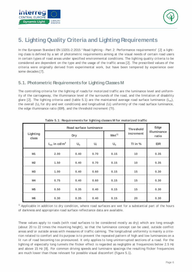
The controlling criteria for the lighting of roads for motorized traffic are the luminance level and uniform-ity of the carriageway, the illuminance level of the surrounds of the road, and the limitation of disability glare [2]. The lighting criteria used (table 5.1) are the maintained average road surface luminance (Lav), the overall (Uo for dry and wet conditions) and longitudinal (Ul) uniformity of the road surface luminance, the edge illuminance ratio (EIR), and the threshold increment (TI).
Table 5.1: Requirements for lighting classes M for motorized traffic
Road surface luminance
Dry Wet1)
Threshold increment
Edge Illuminance
ratio Lighting
class
Lav in cd/m2 Uo Ul Uo TI in % EIR
M1 2.00 0.40 0.70 0.15 10 0.35
M2 1.50 0.40 0.70 0.15 10 0.35
M3 1.00 0.40 0.60 0.15 15 0.30
M4 0.75 0.40 0.60 0.15 15 0.30
M5 0.50 0.35 0.40 0.15 15 0.30
M6 0.30 0.35 0.40 0.15 20 0.30
1) Applicable in addition to dry condition, where road surfaces are wet for a substantial part of the hours of darkness and appropriate road surface reflectance data are available.
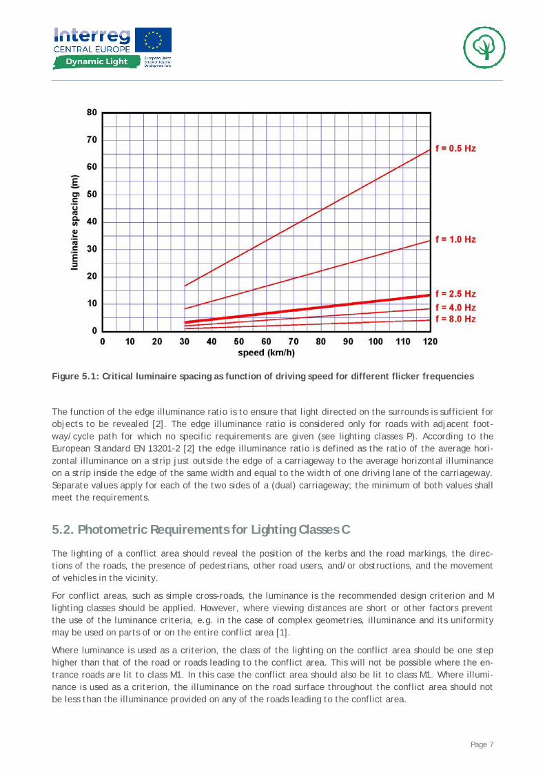
These values apply to roads (with road surfaces to be considered mostly as dry) which are long enough (about 20 to 22 times the mounting height), so that the luminance concept can be used, outside conflict areas and/or outside areas with measures of traffic calming. The longitudinal uniformity is mainly a crite-rion related to comfort and its purpose is to prevent the repeated pattern of high and low luminances on a lit run of road becoming too pronounced. It only applies to long uninterrupted sections of a road. For the lighting of especially long tunnels the flicker effect is regarded as negligible at frequencies below 2.5 Hz and above 15 Hz [8]. For common driving speeds and luminaire spacings the resulting flicker frequencies are much lower than those relevant for possible visual discomfort (figure 5.1).
Page 7
Figure 5.1: Critical luminaire spacing as function of driving speed for different flicker frequencies
The function of the edge illuminance ratio is to ensure that light directed on the surrounds is sufficient for objects to be revealed [2]. The edge illuminance ratio is considered only for roads with adjacent foot-way/cycle path for which no specific requirements are given (see lighting classes P). According to the European Standard EN 13201-2 [2] the edge illuminance ratio is defined as the ratio of the average hori-zontal illuminance on a strip just outside the edge of a carriageway to the average horizontal illuminance on a strip inside the edge of the same width and equal to the width of one driving lane of the carriageway. Separate values apply for each of the two sides of a (dual) carriageway; the minimum of both values shall meet the requirements.
5.2. Photometric Requirements for Lighting Classes C
The lighting of a conflict area should reveal the position of the kerbs and the road markings, the direc-tions of the roads, the presence of pedestrians, other road users, and/or obstructions, and the movement of vehicles in the vicinity.
For conflict areas, such as simple cross-roads, the luminance is the recommended design criterion and M lighting classes should be applied. However, where viewing distances are short or other factors prevent the use of the luminance criteria, e.g. in the case of complex geometries, illuminance and its uniformity may be used on parts of or on the entire conflict area [1].
Where luminance is used as a criterion, the class of the lighting on the conflict area should be one step higher than that of the road or roads leading to the conflict area. This will not be possible where the en-trance roads are lit to class M1. In this case the conflict area should also be lit to class M1. Where illumi-nance is used as a criterion, the illuminance on the road surface throughout the conflict area should not be less than the illuminance provided on any of the roads leading to the conflict area.
Page 8
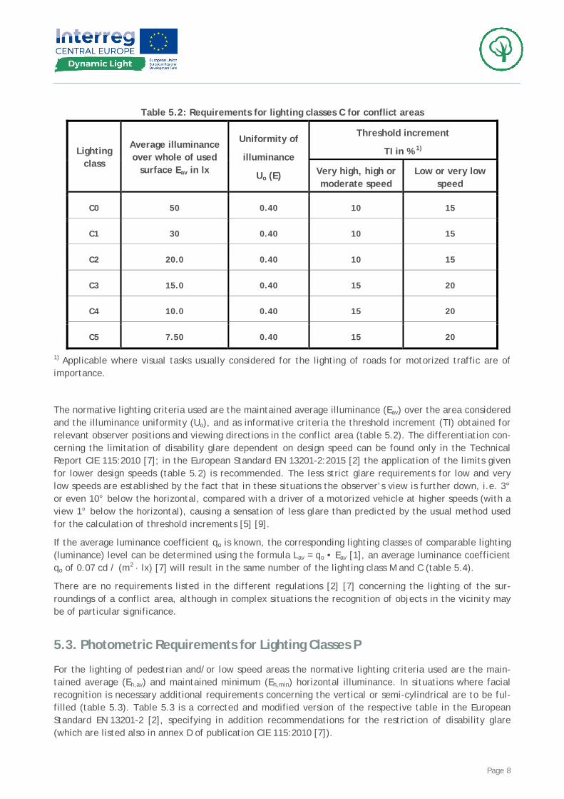
Table 5.2: Requirements for lighting classes C for conflict areas
Threshold increment
TI in % 1) Lighting class
Average illuminance over whole of used
surface Eav in lx
Uniformity of
illuminance
Uo (E) Very high, high or moderate speed
Low or very low speed
C0 50 0.40 10 15
C1 30 0.40 10 15
C2 20.0 0.40 10 15
C3 15.0 0.40 15 20
C4 10.0 0.40 15 20
C5 7.50 0.40 15 20
1) Applicable where visual tasks usually considered for the lighting of roads for motorized traffic are of importance.
The normative lighting criteria used are the maintained average illuminance (Eav) over the area considered and the illuminance uniformity (Uo), and as informative criteria the threshold increment (TI) obtained for relevant observer positions and viewing directions in the conflict area (table 5.2). The differentiation con-cerning the limitation of disability glare dependent on design speed can be found only in the Technical Report CIE 115:2010 [7]; in the European Standard EN 13201-2:2015 [2] the application of the limits given for lower design speeds (table 5.2) is recommended. The less strict glare requirements for low and very low speeds are established by the fact that in these situations the observer’s view is further down, i.e. 3° or even 10° below the horizontal, compared with a driver of a motorized vehicle at higher speeds (with a view 1° below the horizontal), causing a sensation of less glare than predicted by the usual method used for the calculation of threshold increments [5] [9].
If the average luminance coefficient qo is known, the corresponding lighting classes of comparable lighting (luminance) level can be determined using the formula Lav = qo • Eav [1], an average luminance coefficient qo of 0.07 cd / (m2 · lx) [7] will result in the same number of the lighting class M and C (table 5.4).
There are no requirements listed in the different regulations [2] [7] concerning the lighting of the sur-roundings of a conflict area, although in complex situations the recognition of objects in the vicinity may be of particular significance.
5.3. Photometric Requirements for Lighting Classes P
For the lighting of pedestrian and/or low speed areas the normative lighting criteria used are the main-tained average (Eh,av) and maintained minimum (Eh,min) horizontal illuminance. In situations where facial recognition is necessary additional requirements concerning the vertical or semi-cylindrical are to be ful-filled (table 5.3). Table 5.3 is a corrected and modified version of the respective table in the European Standard EN 13201-2 [2], specifying in addition recommendations for the restriction of disability glare (which are listed also in annex D of publication CIE 115:2010 [7]).
Page 9
If the average (diffuse) reflectance ρ is known, the corresponding lighting classes of comparable lighting (luminance) level can be determined using the formula Lav = ρ /π • Eav [1] (table 5.4).
Also for the lighting of pedestrian and/or low speed areas there are no requirements given regarding the lighting of the surrounds of the traffic area under consideration [2] [7]. In cases of well defined (straight) traffic areas, like a residential road, a footway, or a cycle path, it seems advisable to apply a concept similar to the edge illuminance ratio used for roads for motorized traffic. This would help to avoid a sharp cut-off of the lighting at the edges of the traffic area and would improve the sense of safety and security.
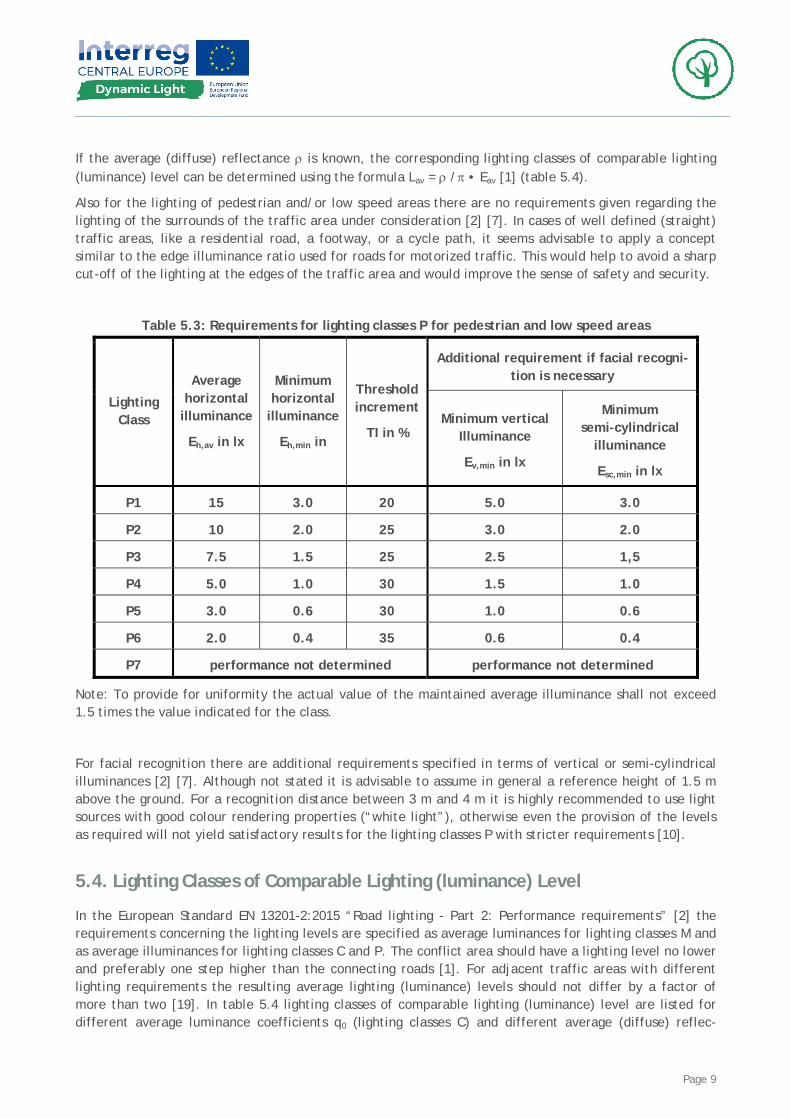
Table 5.3: Requirements for lighting classes P for pedestrian and low speed areas
Additional requirement if facial recogni-tion is necessary
Lighting Class
Average horizontal
illuminance
Eh,av in lx
Minimum horizontal
illuminance
Eh,min in
Threshold increment
TI in % Minimum vertical
Illuminance
Ev,min in lx
Minimum semi-cylindrical
illuminance
Esc,min in lx
P1 15 3.0 20 5.0 3.0
P2 10 2.0 25 3.0 2.0
P3 7.5 1.5 25 2.5 1,5
P4 5.0 1.0 30 1.5 1.0
P5 3.0 0.6 30 1.0 0.6
P6 2.0 0.4 35 0.6 0.4
P7 performance not determined performance not determined
Note: To provide for uniformity the actual value of the maintained average illuminance shall not exceed 1.5 times the value indicated for the class.
For facial recognition there are additional requirements specified in terms of vertical or semi-cylindrical illuminances [2] [7]. Although not stated it is advisable to assume in general a reference height of 1.5 m above the ground. For a recognition distance between 3 m and 4 m it is highly recommended to use light sources with good colour rendering properties (“white light”), otherwise even the provision of the levels as required will not yield satisfactory results for the lighting classes P with stricter requirements [10].
5.4. Lighting Classes of Comparable Lighting (luminance) Level
In the European Standard EN 13201-2:2015 “Road lighting - Part 2: Performance requirements” [2] the requirements concerning the lighting levels are specified as average luminances for lighting classes M and as average illuminances for lighting classes C and P. The conflict area should have a lighting level no lower and preferably one step higher than the connecting roads [1]. For adjacent traffic areas with different lighting requirements the resulting average lighting (luminance) levels should not differ by a factor of more than two [19]. In table 5.4 lighting classes of comparable lighting (luminance) level are listed for different average luminance coefficients q0 (lighting classes C) and different average (diffuse) reflec-
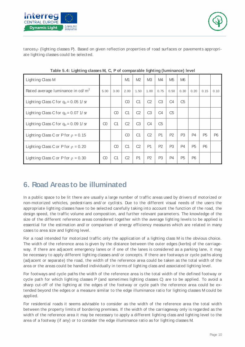
Page 10
tances ρ (lighting classes P). Based on given reflection properties of road surfaces or pavements appropri-ate lighting classes could be selected.
Table 5.4: Lighting classes M, C, P of comparable lighting (luminance) level
Lighting Class M M1 M2 M3 M4 M5 M6
Rated average luminance in cd/m2 5.00 3.00 2.00 1.50 1.00 0.75 0.50 0.30 0.20 0.15 0.10
Lighting Class C for q0 = 0.05 1/sr C0 C1 C2 C3 C4 C5
Lighting Class C for q0 = 0.07 1/sr C0 C1 C2 C3 C4 C5
Lighting Class C for q0 = 0.09 1/sr C0 C1 C2 C3 C4 C5
Lighting Class C or P for ρ = 0.15 C0 C1 C2 P1 P2 P3 P4 P5 P6
Lighting Class C or P for ρ = 0.20 C0 C1 C2 P1 P2 P3 P4 P5 P6
Lighting Class C or P for ρ = 0.30 C0 C1 C2 P1 P2 P3 P4 P5 P6
6. Road Areas to be illuminated In a public space to be lit there are usually a large number of traffic areas used by drivers of motorized or non-motorized vehicles, pedestrians and/or cyclists. Due to the different visual needs of the users the appropriate lighting classes have to be selected carefully taking into account the function of the road, the design speed, the traffic volume and composition, and further relevant parameters. The knowledge of the size of the different reference areas considered together with the average lighting levels to be applied is essential for the estimation and/or comparison of energy efficiency measures which are related in many cases to area size and lighting level.
For a road intended for motorized traffic only the application of a lighting class M is the obvious choice. The width of the reference area is given by the distance between the outer edges (kerbs) of the carriage-way. If there are adjacent emergency lanes or if one of the lanes is considered as a parking lane, it may be necessary to apply different lighting classes and/or concepts. If there are footways or cycle paths along (adjacent or separate) the road, the width of the reference area could be taken as the total width of the area or the areas could be handled individually in terms of lighting class and associated lighting level.
For footways and cycle paths the width of the reference area is the total width of the defined footway or cycle path for which lighting classes P (and sometimes lighting classes C) are to be applied. To avoid a sharp cut-off of the lighting at the edges of the footway or cycle path the reference area could be ex-tended beyond the edges or a measure similar to the edge illuminance ratio for lighting classes M could be applied.
For residential roads it seems advisable to consider as the width of the reference area the total width between the property limits of bordering premises. If the width of the carriageway only is regarded as the width of the reference area it may be necessary to apply a different lighting class and lighting level to the area of a footway (if any) or to consider the edge illuminance ratio as for lighting classes M.
Page 11
Traffic areas used by pedestrians, cyclists, and motorized traffic at low speeds (lighting classes P) are generally bounded by the facades of buildings or property limits of premises.
The dimensions and the lighting level of a traffic area considered as conflict area have to be specified individually. The shape of the reference area could range from a simple rectangle (cross-roads) to a circle or ring (roundabout) to an irregular polygon. In some circumstances it will be necessary to distinguish (in lighting class and level) between the area covering the carriageway between the kerbs and accompanying footway and/or cycle path areas.
In urban environments it might be desirable to enhance particular building facades using some light pro-vided by the road lighting installation. In these cases the luminous flux onto the facades has to be re-garded as useful light although it might lower the energy efficiency of the road lighting as such.
7. Areas not to be illuminated To safeguard and enhance the night time environment it is necessary to control obtrusive light (also known as light pollution), which could present physiological and/or ecological problems to surroundings and people, to flora and fauna [11] [12]. Obtrusive light in defined as spill light, which because of quanti-tative, directional or spectral attributes in a given context, gives rise to annoyance, discomfort, distrac-tion or a reduction in the ability to see essential information [7] [11] [12].
Roads for motorized traffic or footways/cycle paths through intrinsically dark areas like national parks or low brightness areas such as residential or rural areas should not be lit outside the traffic area, including the area to be considered regarding the edge illuminance ratio or an equivalent measure. Possible limits for the horizontal illuminance outside the traffic area are the maximum illuminance cause by full moon light or from full moon at a height of 25° above the horizon with 0.25 lx or 0.1 lx respectively, or the hori-zontal illuminance caused by the star light at new moon with 0.001 lx.
The lighting of a footway and/or cycle path only alongside a rural road connecting e.g. some residential areas should not cause glare for the users of the unlit carriageway. For such a situation the limit for the maximum threshold increment TI as specified in the European Standard EN 12464-2 “Light and lighting - lighting of work spaces - Part 2: Outdoor work places” [11] is 15 % assuming an adaptation luminance of 0.1 cd/m2.
Road lighting installations could produce too high (vertical) illuminances on properties or the road lighting luminaires could cause glare for observers on e.g. balconies or terraces. Limits for maximum illuminances on properties can be found in the European Standard EN 12464-2 [11]. A comprehensive method for the evaluation of glare is described in a German publication on the limitation of obtrusive light [13]. Careful shielding could help to minimize annoyance and discomfort.
Astronomical observations are affected by artificial sky glow, i.e. the brightening of the night sky that results from the reflection of visible and non-visible radiation, scattered from the constituents of the at-mosphere in the direction of observation [7]. It includes radiation that is emitted directly from the lumi-naires (at and above the horizontal) and radiation that is reflected from the (traffic) areas lit on purpose and from areas outside. Therefore light at and above the horizontal should be minimized; limits for the maximum upward light ratios are provided in the European Standard EN 12464-2 [11]. To evaluate the light reflected by the ground and to compare this component with the light emitted directly from the luminaires a method using the upward flux ratio has been developed in France [14].
Where building facades, monuments etc. are illuminated using parts of the road lighting or separate flood-lighting installations proper aiming in such a way that the luminous flux emitted is directed totally to-wards the area to be illuminated - i.e. to aim at an utilance of 100 % - will help to minimize direct and reflected sky glow [15].
Page 12
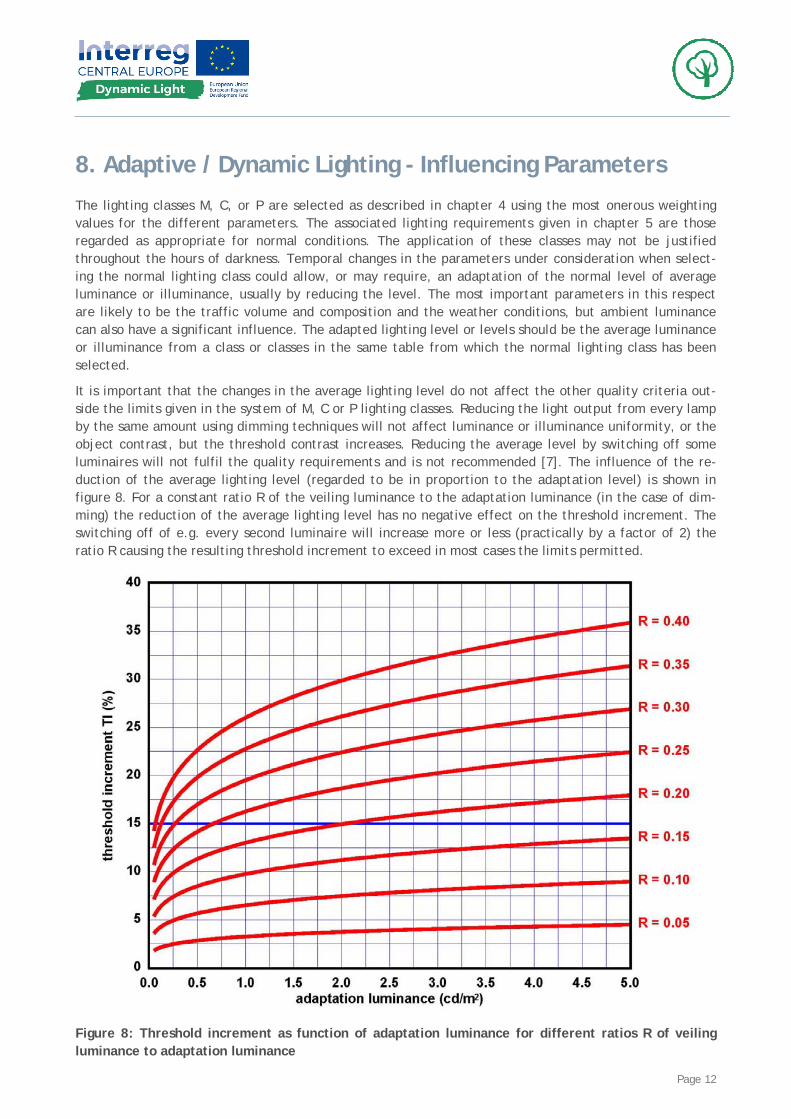
8. Adaptive / Dynamic Lighting - Influencing Parameters The lighting classes M, C, or P are selected as described in chapter 4 using the most onerous weighting values for the different parameters. The associated lighting requirements given in chapter 5 are those regarded as appropriate for normal conditions. The application of these classes may not be justified throughout the hours of darkness. Temporal changes in the parameters under consideration when select-ing the normal lighting class could allow, or may require, an adaptation of the normal level of average luminance or illuminance, usually by reducing the level. The most important parameters in this respect are likely to be the traffic volume and composition and the weather conditions, but ambient luminance can also have a significant influence. The adapted lighting level or levels should be the average luminance or illuminance from a class or classes in the same table from which the normal lighting class has been selected.
It is important that the changes in the average lighting level do not affect the other quality criteria out-side the limits given in the system of M, C or P lighting classes. Reducing the light output from every lamp by the same amount using dimming techniques will not affect luminance or illuminance uniformity, or the object contrast, but the threshold contrast increases. Reducing the average level by switching off some luminaires will not fulfil the quality requirements and is not recommended [7]. The influence of the re-duction of the average lighting level (regarded to be in proportion to the adaptation level) is shown in figure 8. For a constant ratio R of the veiling luminance to the adaptation luminance (in the case of dim-ming) the reduction of the average lighting level has no negative effect on the threshold increment. The switching off of e.g. every second luminaire will increase more or less (practically by a factor of 2) the ratio R causing the resulting threshold increment to exceed in most cases the limits permitted.
Figure 8: Threshold increment as function of adaptation luminance for different ratios R of veiling luminance to adaptation luminance
Page 13
The use of adaptive lighting can provide significant reductions in energy consumption, compared with operating the normal lighting class throughout the hours of darkness. It can also be used to reduce energy consumption by reducing the lamp light output to the maintained value when the installation is clean and the lamps are new [7]. In simple cases there will be just one fixed time interval, e. g. from 11 p.m. in the evening to 4 a.m. in the morning, of a reduced lighting level. In more complex situations switching pro-files with more than three to four time spans and/or lighting levels could be found [7].
The different parameters to be taken into account while selecting an appropriate lighting class M, C, or P have a or more or less pronounced impact on the weighing values, i.e. on the lighting classes and the as-sociated lighting requirements.
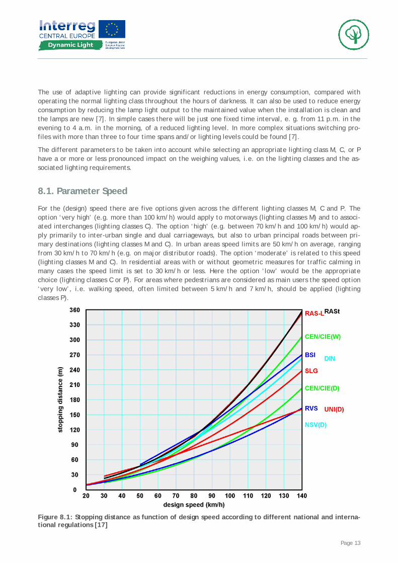
8.1. Parameter Speed
For the (design) speed there are five options given across the different lighting classes M, C and P. The option ‘very high’ (e.g. more than 100 km/h) would apply to motorways (lighting classes M) and to associ-ated interchanges (lighting classes C). The option ‘high’ (e.g. between 70 km/h and 100 km/h) would ap-ply primarily to inter-urban single and dual carriageways, but also to urban principal roads between pri-mary destinations (lighting classes M and C). In urban areas speed limits are 50 km/h on average, ranging from 30 km/h to 70 km/h (e.g. on major distributor roads). The option ‘moderate’ is related to this speed (lighting classes M and C). In residential areas with or without geometric measures for traffic calming in many cases the speed limit is set to 30 km/h or less. Here the option ‘low’ would be the appropriate choice (lighting classes C or P). For areas where pedestrians are considered as main users the speed option ‘very low’, i.e. walking speed, often limited between 5 km/h and 7 km/h, should be applied (lighting classes P).
Figure 8.1: Stopping distance as function of design speed according to different national and interna-tional regulations [17]
Page 14
From the road safety point of view the relationship between speed and stopping distance is one of the most important aspects. The stopping distance is the sum of two stretches, i.e. the distance covered dur-ing the reaction time and the distance covered during the breaking time. A simplified method, assuming a constant friction coefficient, for the evaluation of stopping distances is described in the CEN Technical Report CR 14380:2002 ‘Tunnel lighting’ [16]. For known friction coefficients the stopping distance is a function of speed, and can be calculated for a given slope of the road assuming a certain reaction time. In recommendations and regulations across Europe the specified reaction time varies between 1 s and 2 s, and friction coefficients for dry and wet conditions are not harmonized at all. Figure 8.1 shows the rela-tionships between design speed and stopping distance as given in different European recommendations and regulations on road and tunnel lighting [17]. For the relevant speeds between 30 km/h and 100 km/h the resulting absolute stopping distances differ by a factor of almost two, but in all cases the decrease of the stopping distance as a function of speed is significant. As an example, the stopping distance for a speed of 30 km/h (option ‘low’) is on average shorter by a factor of two compared to the stopping dis-tance for a speed of 50 km/h (option ‘moderate’).
At a speed of 30 km/h the length of the area in front of a car lit by its own vehicle headlights is approxi-mately equivalent to the stopping distance. In this case road lighting should be provided predominantly for all non-motorized road users, usually moving at a lower speed. It can be concluded that the reduction of the lighting level as function of speed as indicated by the weighting values for the different lighting classes is in principal appropriate; but the difference of the weighting values between ‘high’ and ‘moder-ate’ seems to be questionable as it allows a change of the average lighting level by a factor of two.
8.2. Parameter Traffic Volume
When designing a new road or re-designing an existing road the traffic volume to be expected in the near future, i.e. in the next 10 to 15 years, is one of the main design criteria. In this respect the parameter ‘traffic volume’ (lighting classes M and C) is linked to the absolute values of the average daily traffic. If the parameter ‘traffic volume’ is considered in terms of the (relative) actual traffic volume in comparison to the design value, the selection of the option could be modified at a second stage (for temporal rea-sons). The traffic volume of a road designed for a ‘high’ volume, but with an actual traffic volume of e.g. less than 50 % of the design value, could be classified as ‘moderate’, and with an actual traffic volume of e.g. less than 25 % as ‘low’. In this case the actual traffic volume is not considered as being measured continuously, but as known (or assumed) from daily, weekly, monthly, or seasonal profiles of the traffic volumes as available. This approach could be applied in a similar way to traffic volumes classified (based on absolute values) as ‘moderate’.
It is generally accepted that the risk increases with driving speed and traffic volume. In this respect the knowledge of the actual traffic volume in comparison to the traffic volume considered at the design stage of the road offers the opportunity to apply adaptive /dynamic lighting, i.e. to adjust the lighting level in accordance with the appropriate lighting class linked to the sum of the weighting values.
8.3. Parameter Traffic Composition
The parameter ‘traffic composition’ has been introduced to consider the influence of different users of a certain traffic area on the resulting risk caused e.g. by differences in the speed of movement and/or changes of the visual conditions. For lighting classes M and C, predominantly intended for motorized traf-fic, the influence of the amount of non-motorized users in taken into account by the options ‘mixed’ and ‘mixed with high percentage of non-motorized’. In a similar way the option ‘mixed’ could be interpreted as a mixture of cars and (a higher percentage) of trucks. For lighting classes P, predominantly intended of pedestrian and low speed traffic, the parameter ‘traffic composition’ allows to take into account the dif-
Page 15
ferent users, pedestrians, cyclists, and motorized vehicles, (separate or together) of a traffic area at a certain moment.
If during certain hours of darkness, e.g. between 11 p.m. and 5 a.m., the number of non-motorized users is (assumed or known to be) low, the option for the parameter traffic composition could be changed from ‘mixed with high percentage of non-motorized’ to ‘mixed’ (for lighting classes M and C). In pedestrian and low speed areas (lighting classes P) the access for motorized vehicles and/or cycles is quite often re-stricted to certain hours of a day and/or to certain days of a week. If these time frames coincide with some hours of darkness the option for the parameter traffic composition may be reconsidered and ad-justed (e.g. no motorized vehicles, no cyclists). In all these cases the temporal change of the traffic com-position could result in reduced lighting requirements, i.e. adaptive / dynamic lighting could be applied to provide the appropriate lighting levels.
8.4. Parameter Separation of Carriageways
The separation of carriageways (considered only for lighting classes M and C) is regarded as an effective safety measure, in particular in form of a central reserve of not less then three metres in width with guardrails for ‘high’ and ‘very high’ speed roads. If, from long term observations of the traffic volume profiles, it is known that during certain hours of darkness one of the carriageways is carrying considerably less traffic than the other, adaptive / dynamic lighting could be used to provide different adequate light-ing levels for the two carriageways.
If only one carriageway is used temporarily, e.g. during road works, the higher risk without separation could be counterbalanced with a speed reduction. This is reflected in the selection process for M (table 4.1) and C (table 4.2) lighting classes. An appropriate choice of the options for the parameters ‘speed’ and ‘separation of carriageways’ will result in an unchanged weighting value, i.e. in unaltered lighting requirements.
8.5. Parameter Junction Density
According to the European Technical Report CEN/TR 13201-1:2014 “Road lighting - Part 1: Guidelines on selection of lighting classes” [1] the intersection density (for lighting classes M only) is considered as ‘high’ if there are more than three intersections per kilometre, else it is rated as ‘moderate’. The inter-section is defined as the general area where two or more roads join at the same level [1]. The limit of three intersections per kilometre is in line with general assumptions concerning the application of the luminance concept; i.e. a more or less straight section of the road of a length not less than 20 to 22 times the mounting height and the evaluation of disability glare taking into account all luminaires up to a dis-tance of 500 m in front of the road user [3].
In a similar way the intersection density is considered as ‘moderate’ for interchange spacings - or dis-tances between bridges respectively - greater than or equal three kilometres, else it is rated as ‘high’ [1]. Here the interchange is defined as a grade separated junction with one or more turning roadways (ramps) for travel between the through roads [1].
The intersection density is an intrinsic property of the overall road layout. Under these circumstances the application of adaptive / dynamic lighting is not adequate unless it is foreseen that in the not too distant future the number of intersections will be increased considerably, and at the same time leading to an increased traffic volume. In such cases adaptive / dynamic lighting could be used at an appropriately re-duced lighting level until the road is in full operation.
Page 16
8.6. Parameter Parked Vehicles
Parked vehicles are regarded as obstacles on the road, increasing the general risk and causing some ob-struction to the driver’s view. Therefore the parameter ‘parked vehicles’ with the options ‘present’ and ‘not present’ is considered to be important for all lighting classes (M, C, and P). In the simplified approach using only whole numbers it is not possible to take into account the speed dependence of the risk [1]. The presence of parked vehicles could be restricted to certain hours of a day or to certain days of a week. For example on single or dual carriageways (lighting classes M and C) parked vehicles on the carriageway may not be allowed during rush hours, in pedestrian areas (lighting classes P) motorized traffic is restricted generally.
If the hours of darkness coincide to some extend with the hours of restricted parking, the option for the parameter parked vehicles could be changed from ‘present’ to ‘not present’, resulting in reduced lighting requirements. At the same time, e.g. during rush hours on a single or dual carriageway, an increased traf-fic volume could be expected, possibly demanding a higher lighting level (see 8.2.). Depending on specific circumstances adaptive / dynamic lighting could be applied, but decisions have to be taken with great care. The energy consumption savings may not justify the higher complexity and costs of the installation. There is also no clear guidance how to classify that part of a carriageway (the outer lane) which is occu-pied by the parked vehicles. Is the outer parking lane as part of the carriageway to be considered as a conflict area (lighting classes C, illuminance based requirements), or are lighting classes M for motorized traffic applicable, although these classes are linked to the luminance concept, i.e. to the average lumi-nance of the road surface which cannot be seen by the road users due to the parked vehicles?
8.7. Parameter Ambient Luminance
The parameter ambient luminance is used to take into account the ambient brightness level (in the visual field) which is defined as the assessed luminance level of the surroundings [1]. In the European Technical Report CEN/TR 13201-1:2014 “Road lighting - Part 1: Guidelines on selection of lighting classes” [1] the ambient luminance (wrongly termed luminosity) is regarded as one of the parameters for which significant variations may apply at different periods of the hours of darkness. In the tables of the parameters for the selection of lighting classes M, C, or P the option ‘high’ is associated with ‘shopping windows, advertise-ment expressions, sport fields, sports areas and storage areas’ [1]. This can be regarded as some kind of guidance only as this does not reflect the actual situations.
The luminance (brightness) distribution in the visual field controls the adaptation level of the eyes. The higher the adaptation level of the visual system, the more sensitive it is to low contrasts, and less sensi-tive it is to glare [18]. The adaptation luminance is usually approximated by the average road surface lu-minance in front of the road user created by the road lighting installation. If the surroundings, in particu-lar the (vertical) facades of buildings, provide some additional lighting of the road, e.g. by reflecting light from the road lighting installation, without causing a proportional increase of the illuminance at the ob-server’s eye (i.e. of the veiling luminance responsible for disability glare), the visual conditions will im-prove. In this case the ratio R of the veiling luminance to the adaptation luminance will decrease, and in consequence the threshold increment TI will be lower, as shown in figure 8. The option ‘moderate or ‘low’ for the parameter ambient luminance would be the appropriate choice.
If parts of the surroundings, e.g. shop windows, displays, advertisement signs, are so bright that a signifi-cant increase of the veiling luminance is to be expected, a higher adaptation luminance, approximated by the average road surface luminance, has to be provided to keep the visual conditions, here expressed in terms of the threshold increment TI, at the required level. Depending on the original lighting level and on the expected (or calculated for critical situations foreseen) change of the ratio of veiling luminance to adaptation luminance the option for the parameter ambient luminance has to be changed appropriately to ‘moderate’, or even ‘high’. This could lead to an increase of the required lighting level by a factor of two.

Page 17
In extreme cases, e.g. using video walls with average luminances of several hundred cd/m2, it is not real-istic to counterbalance the possible glare by increasing the lighting level; dimming of such ‘glare’ sources during the hours of darkness would be the obvious choice.
Some of the glare sources will be regarded as obtrusive light which is defined as light giving rise to annoy-ance, discomfort, distraction or a reduction in the ability to see essential information [12]. For the control of obtrusive lighting in general stricter requirements apply during certain periods of the night (curfew), usually fixed by local authorities [12]. If the time frame is given adaptive / dynamic lighting could be ap-plied to reduce the lighting level accordingly, offering some energy consumption savings without impairing the road safety. It should be noted hat the reduction of the average lighting level by dimming has no negative effect on the threshold increment (figure 8), but switching off e.g. every second luminaire will increase the ratio R causing the resulting threshold increment to exceed the limits permitted in most cases.
8.8. Parameter Navigational Task / Visual Guidance / Traffic Control
The execution of guidance manoeuvres is assisted by traffic safety devices, like road surface markings, delineators, and/or traffic signs or lights. The parameter ‘difficulty of navigational task’, defined as the degree of effort necessary by the road user, as a result of the information presented, to select route and lane, and to maintain or change speed and position on the carriageway, is used to take account of the existence of such devices and/or of the difficulty to recognize them at adverse weather conditions [1]. ‘Visual guidance’ provided by the road is part of this information [1]. Traffic signs or traffic lights, here considered as parameter ‘traffic control’, could help to reduce the overall risk.
The option to be selected (between ‘very difficult’, ‘difficult’, and ‘easy’) for the given situation could have a significant influence on the lighting requirements. If the lighting installation has been designed to fulfil the requirements for ‘very difficult’ conditions, e.g. for adverse (winter) weather conditions, adap-tive / dynamic lighting could be applied to reduce the lighting level during periods of ‘easy’ conditions, e.g. during the dry summer. The decision to change the lighting level for a longer period of time should be based principally on long term observation/experience. A dynamic adaptation requires probably quite sophisticated (and expensive) measuring equipment which may not be justified by the (relatively small) amount of possible energy savings.
The provision of traffic lights, in particular in conflict areas, could allow to change the option from ‘diffi-cult’ to ‘easy’ and to adjust the lighting requirements accordingly. (In some cases the conflict area will not be a conflict area any longer.) However, if the surroundings are intrinsically dark, and the option for the parameter ‘ambient luminance’ is selected as ‘low’, traffic lights could become a glare source, thus requiring a higher lighting level. Switching off the traffic lights during certain hours of darkness could in-crease the overall risk which could be compensated by an increase of the (adaptive) lighting level. In such situations adaptive / dynamic lighting cannot really contribute to energy consumption savings.
8.9. Parameter Facial Recognition
The parameter ‘facial recognition’ is considered only for lighting classes P, intended predominantly for pedestrians. The recognition of another pedestrian’s face at a certain distance requires some vertical lighting at a height of about 1.5 m above the ground. According to the lighting requirements for pedes-trian and low speed areas as specified in the European Standard EN 13201-2 [1] the level of the vertical illuminance should be about one third, the level of the semi-cylindrical illuminance about one fifth of the horizontal illuminance (table 5.3). If this is accomplished with increased lighting or even better with addi-tional lighting using more appropriate intensity distributions or multi-distribution luminaires, adaptive / dynamic lighting could be applied to adjust the lighting during certain hours of darkness dependent on the expected or actual traffic flow of pedestrians.
Page 18
8.10. Other Parameters
In the first edition of the European report CEN/TR 13201-1:2004 ‘Road lighting - Part 1: Selection of light-ing classes’ [19] there have been further parameters listed for consideration. For moderate and low speed traffic areas (lighting classes M and C) special attention was given to the (geometry related) parameter ‘measures for traffic calming’. Generally only in the area of traffic calming the higher lighting require-ments of the lighting class numbered one step lower have to be fulfilled [19]. This is equivalent to the consideration of an area of traffic calming as a conflict area.
For traffic areas for motorized traffic (lighting classes M) the ‘main weather type’ was considered as a special parameter [19] resulting in slightly different lighting requirements for ‘dry’ and ‘wet’ conditions of the road surface. These requirements have been harmonized in the Technical Report CIE 115:2010 “Light-ing of roads for motor and pedestrian traffic” [7] and in the European Standard EN 13201-2:2015 “Road lighting - Part 2: Performance requirements” [2]. The overall uniformity for wet conditions is the only additional requirement to be applied if the road surfaces are rated ‘wet’ for an expected substantial part of the hours of darkness and appropriate road surface data are available. Therefore the ‘main weather type’ has not to be regarded as a special parameter as long as the associated lighting requirements are applied.
All in all the parameters discussed in this chapter do not offer a substantial extension beyond the parame-ters used for the selection of an appropriate lighting class M (table 5.1 for motorized traffic), C (table 5.2 for conflict areas), or P (table 5.3 for pedestrian and low speed areas), and they do not show a relevance for the application of adaptive / dynamic lighting.
9. Alternative Method for Selection of Lighting Classes The alternative method for the selection of a lighting class, described in the informative annex B of the Technical Report CEN/TR 13201-1:2014 [1], is based on a functional or administrative classification of roads. For lighting classes M and C road designation ranges from interurban motorways (speed limit less equal 130 km/h) to dangerous sections of urban roads (speed limit less equal 30 km/h), for lighting classes P from low speed roads (speed limit between 5 km/h and 40 km/h) to roads without motorized traffic, walkways and bicycle tracks. The five parameters considered, besides the road type, are in all cases the speed limit, the traffic composition and traffic volume, the ambient light, and the mental task load / the facial recognition respectively.
For a given road category, from the multiplication of the five coefficients associated with the selected options per parameter results an overall coefficient (in some way rounded to a whole number). Transfer-ring the overall coefficient on to the appropriate graphic presentation leads to an average luminance (for lighting classes M) or illuminance (for lighting classes C or P) to be applied to the given lighting situation. The lighting classes of comparable lighting level are selected based on the same assumptions concerning the average luminance coefficients q0 and the average diffuse reflectances ρ as described in chapter 5.4. If facial recognition is regarded as a requirement, the associated coefficient and hence the overall coeffi-cient could yield a lighting class P with higher requirements - in terms of average and minimum horizontal illuminances. An increase of the horizontal illuminance (on the ground) will not necessarily result in an equivalent increase of the vertical or semi-cylindrical illuminance at eye height which would be required for an adequate facial recognition. Therefore the European Standard EN 13201-2:2015 “Road lighting - Part 2: Performance requirements” [2] lists additional requirements for lighting classes P in terms of minimum vertical illuminances (in the order of one third of the average horizontal illuminances) or of minimum semi-cylindrical illuminance (in the order of one fifth of the average horizontal illuminances).

Page 19
10. Energy Efficiency For road lighting installations of equivalent geometry, lighting level, and operating mode a number of different measures could be used to describe and to compare the energy efficiency. These measures are usually based on the installed electrical power or on the annual electrical energy consumption of an in-stallation. In the European Standard EN 13201-5:2015 2015 “Road lighting - Part 5: Energy performance indicators” [3] a methodology is described how to calculate energy performance indicators for road light-ing installations using the power density indicator (PDI) and the annual energy consumption indicator AECI). The installed power is the given (fixed) maximum necessary to fulfil the most demanding lighting requirements. The (variable) annual energy consumption depends not only on the installed power but also on the mode of operation (adaptive /dynamic lighting), and in principal on the varying availability of natu-ral light due to changing environmental conditions. Installations of equivalent lighting level but different in size of the traffic areas to be illuminated could be compared using measures which relate e.g. the in-stalled power or the annual energy consumption to the lit area. If installations of equivalent geometry but with different lighting levels are to be compared, energy efficiency measures should be preferred which relate e.g. the installed power or the annual energy consumption to the average lighting level over the traffic area under consideration. In more complex situations, i.e. irregular shaped traffic areas with dif-ferent lighting levels, it is advisable to use energy efficiency measures such as installed electrical power per surface area and per illumination unit or the annual energy consumption over time for a well defined annual switching profile [20].
10.1. Power Related Energy Efficiency Measures
For the comparison of the energy efficiency of road lighting installations of equivalent lighting level but serving traffic areas of different size the installed system power (Pel in W) of an installation could be re-lated to the size of the associated areas (A in m2). This type of efficiency measure is usually called the power density of an installation (in W / m2). For roads of constant width, power densities could also be compared if they are expressed in kW / km. For lighting classes M it is advisable to include the area(s) of the strip(s) along the carriageway(s) for the evaluation of the edge illuminance ratio where applicable. Otherwise the resulting power densities will not match the values obtained for situations with require-ments for footways / cycle paths along the carriageway(s) of the same dimensions (where the edge illumi-nance ratio is not applicable).
For the comparison of lighting installations of the same geometry (size) but with different lighting levels the installed system power (Pel in W) of an installation could be related to the required or provided light-ing level, usually expressed as average illuminance (Eav in lx). This type of energy efficiency measure is called specific power (in W / lx). If one installation is providing the lighting for more than one traffic area with different lighting requirements, an area weighted average lighting level has to be taken into account.
In cases of road lighting installations with different lighting levels and areas of different size the installed system power (Pel in W) of an installation could be related to the required or provided lighting level, usu-ally expressed as average illuminance (Eav in lx) and to the size of the associated area (A in m2). This type of energy efficiency measure is called the specific power density D, in W / (m2 ⋅ lx) which is equivalent to W / lm. Here it could be necessary to convert e.g. average luminances and/or hemispherical illuminances into horizontal illuminances to make comparisons possible using the common quantity luminous flux. Con-siderations concerning the edge illuminance ratio and the weighting of different lighting levels apply as described for the power density and/or for the specific power. The inverse of the specific power density in W / lm can be regarded as installation efficacy or as installation efficiency in lm / W depending on the type of the reference lighting level [3].
Page 20
It should be noted that power related comparisons are valid only under the assumption that all relevant lighting quality parameters are considered and fulfilled. If there are large differences between lighting classes in terms of uniformities and glare control, comparisons of installations showing different lighting levels should be carried out with great caution as results could be misleading due to the fact that less strict lighting requirements (e.g. uniformities, glare control) could have been converted into higher light output ratios and/or higher utilances.
10.2. Consumption Related Energy Efficiency Measures
The maximum annual energy consumption of a road lighting installation is given by the total installed electric power of the installation multiplied by the annual time of operation. The operating time of a road lighting installation per day depends on the availability of natural daylight, i.e. on the variable number of hours per day for which the lighting level is below a certain value. The lighting level which triggers the operation of the road lighting installation in turn depends on the specified lighting requirements, on the overall installation layout (geometry, obstruction etc.) and on the properties of the different components (e.g. run-up time of lamps/light sources). If, during the hours of darkness a number of different lighting levels are being applied (adaptive / dynamic lighting) over certain time intervals (per day), the associated electric powers have to be taken into account for the calculation of the energy consumption.
Temporal variations of the different parameters considered (chapter 8) could result in possibly reduced lighting levels (and uniformities) compared to those necessary to fulfil the most demanding requirements. Following the procedures (described in chapter 4) to select an appropriate lighting class M, C, or P a change of the weighting value between one and two can be expected for the different parameters: speed (1), traffic volume (2, restricted 1), traffic composition (1), parked vehicles (1), ambient luminance (2), and difficulty of navigational task (1). In terms of the lighting requirements a reduction of the sum of the weighting values by two is equivalent to a 50 % reduction of the average lighting level. Only in some few cases a larger deviation from the original design value will occur, i.e. in the majority of road lighting in-stallations adaptive / dynamic lighting could be realized in an effective and inexpensive way using just two lighting levels.
The annual electrical energy consumption (Wel, a in kWh / a) could be used as an energy efficiency meas-ure to compare different road lighting installation provided the lighting requirements (including the oper-ating mode) are equivalent and the reference areas are of the same size. In this case annual energy con-sumptions could also be compared if they are expressed in kWh / (a ⋅ km).
If the annual energy consumption is used to compare road lighting installations of equivalent lighting level (and operating mode) but of different size of the reference areas the consumptions should be related to the size of the associated areas (in m2). This type of energy efficiency measure could be called the annual energy consumption density in kWh / (a ·m2). For practical reasons it may be appropriate to specify values of the energy consumption density in terms of kWh per 1000 h and per 1000 m2.
If the annual energy consumption is used to compare road lighting installations of the same size but with different lighting levels (and operating modes) the consumptions should be related to the required or pro-vided lighting levels, usually expressed as average illuminances (in lx). This type of energy efficiency measure could be called the specific annual energy consumption in kWh / (a · lx).
Finally, if the annual energy consumption is used to compare road lighting installations of different light-ing levels (and operating modes) and of different size of the reference areas the consumptions should be related to the required or provided lighting levels, usually expressed as average illuminances (in lx) and to the size of the associated areas (in m2). This type of energy efficiency measure could be called the spe-cific annual energy consumption density in kWh / (a ⋅ lx · m2). Considerations concerning the edge illumi-nance ratio and the weighting of different lighting levels apply here in the same way as described for the power related efficiency measures (chapter 10.1).
Page 21
It should be noted that also energy consumption related comparisons are valid only under the assumption that all relevant lighting quality parameters are considered and fulfilled. If there are large differences between lighting classes in terms of uniformities and glare control, comparisons of installations showing different lighting levels should be carried out with great caution as results could be misleading due to the fact that less strict lighting requirements (e.g. uniformities, glare control) could have been converted into higher light output ratios and/or higher utilances. Furthermore the energy consumption depends heavily on operating times and modes which are influenced by the geographic latitude and/or by socio-economic and other factors [3] [20].
11. Conclusions The concept of adaptive lighting has been first introduced in Publication CIE 115:2010 “Lighting of roads for motor and pedestrian traffic” [7]. This Technical Report was written in a global and broad manner taking into account the most relevant parameters having an impact on the requirements for the lighting of roads. The document was intended as a framework for the development of national codes of practice and standards. The European Technical Report CEN/TR 13201-1:2014 “Road lighting - Part 1: Guidelines on selection of lighting classes” [1] is based on Publication CIE 115:2010 [7], but showing some anomalies and simplifications which are a hindrance to the transformation of the CEN Technical Report [1] into national recommendations, regulations or standards. In a number of countries (also participating in this INTERREG project) the national standards organizations have elaborated or are elaborating national standards on the selection of lighting classes; namely in Italy the standard UNI 11248 “Illuminazione stradale - Selezione delle categorie illuminotecniche” [21] has been published in November 2016, in Austria the standard O 1055:2017 “Straßenbeleuchtung - Auswahl der Beleuchtungsklassen” [22] has been published in August 2017, and in Germany a standard DIN 13201-1 “Straßenbeleuchtung - Teil 1: Auswahl der Beleuchtungs-klassen” [23] is expected to be published in 2018.
The parameters to be taken into account are generally related to the fixed geometry of the area under consideration, to the time dependent traffic use of the area, and to the time dependent influence of the surrounding environment. For the application of adaptive / dynamic lighting it is useful to distinguish be-tween fixed and time dependent parameters during the selection of an appropriate lighting class. A func-tional or administrative classification and designation of roads [1] could lead to a simplified selection pro-cedure insofar as only some relevant time dependent parameters have to be considered. If categorized roads are associated not only with fixed but also with in principal time dependent parameters, e.g. maxi-mum traffic flow [21] or ambient luminance [22], the comparison with the actual situation, possibly sup-ported by a risk analysis, could lead to (usually) a reduction of the lighting level, i.e. the application of adaptive / dynamic lighting. Where the pattern of variation in parameter values is well known, such as from records of traffic counts on traffic routes, or can be reasonably assumed, as in many residential ar-eas, a simple time based control system may appropriate. In other situations an interactive control system linked to real-time data may be preferred. In some national standards the measurement and application of real-time data, e.g. of traffic flow, is described [21] [22], in another standard [23] no guidance is given how to link the traffic flow with an appropriate lighting level. The decision has to be taken from experi-ence and knowledge. All in all the application of adaptive / dynamic lighting is regarded as a very useful tool to reduce energy consumption, light pollution, and CO2-emission while keeping road safety and secu-rity at an appropriate level. Unfortunately the current European Technical Report CEN/TR 13201-1:2014 “Road lighting - Part 1: Guidelines on selection of lighting classes” [1] is not written in a form which would allow national standardization organizations to implement it as a national standard. It is hoped and should be possible to come to a consensus of opinion regarding road categories and fixed or time dependent pa-rameters to be considered for a particular road situation while elaborating the next revision of EN/TR 13201 starting in 2020.

Page 22
12. References [1] CEN/TR 13201-1:2014 “Road lighting - Part 1: Guidelines on selection of lighting classes”
[2] EN 13201-2:2015 “Road lighting - Part 2: Performance requirements”
[3] EN 13201-5:2015 “Road lighting - Part 5: Energy performance indicators”
[4] EN 13032-5:2018 “Light and lighting - Measurement and presentation of photometric data of lamps and luminaires - Part 5: Presentation of data for luminaires used for road lighting”
[5] EN 13201-3:2015 “Road lighting - Part 3: Calculation of performance”
[6] EN 13201-4:2015 “Road lighting - Part 4: Methods for measuring lighting performance”
[7] Technical Report CIE 115:2010 “Lighting of roads for motor and pedestrian traffic”, 2nd edition, Vienna
[8] CEN Report CR 14380:2003 “Lighting applications - Tunnel lighting”
[9] Technical Report CIE 140:2000 “Road lighting calculations”, Vienna
[10] Raynham, P. et al. “White light and facial recognition”, The Lighting Journal, January/February 2003, p. 29-33
[11] EN 12464-2:2014 “Light and lighting - Lighting of work spaces - Part 2: Outdoor work places”
[12] “Guide on the limitation of the effects of obtrusive light from outdoor lighting installations, CIE 150:2003, Vienna
[13] “Empfehlungen zur Messung, Beurteilung und Minderung von Lichtimmissionen künstlicher Lichtquellen”, LiTG Publikation 12.3, Berlin, 2011 (in German)
[14] “Eclairages extérieurs - Les nuisances dues à la lumière”, AFE Guide, Paris, 2006 (in French)
[15] Stockmar, A. “Assessment of obtrusive light – the European approach”, Conference Proceedings “Urban Nightscape 2006”, Athens, p. 200-202
[16] CEN CR 14380:2002 “Tunnel lighting”
[17] Stockmar, A. “Tunnel lighting - recommendations and regulations 2010”, Proceedings Outdoor Lighting Seminar, 07.10.2010, Oslo
[18] Technical Report CIE 100:1992, “Fundamentals of the visual task of night driving”, 1st edition, Vienna
[19] CEN/TR 13201-1:2004 “Road lighting - Part 1: Selection of lighting classes”, 1st edition
[20] Stockmar, A. “Energy efficiency measures for outdoor lighting”, Light & Engineering, Vol. 19, No. 4, pp. 15-19, 2011
[21] UNI 11248 “Illuminazione stradale - Selezione delle categorie illuminotecniche”, 2016
[22] O 1055 “Straßenbeleuchtung - Auswahl der Beleuchtungsklassen”, 2017

Page 23
[23] E DIN 13201-1: “Straßenbeleuchtung - Teil 1: Auswahl der Beleuchtungsklassen”, 2018