Embed Size (px)
Citation preview
1
1. Hand Tools2. Types
2.1 Hand tools 2.2 Hammer Drill 2.3 Rotary hammer drill 2.4 Cordless drills 2.5 Drill press 2.6 Geared head drill 2.7 Radial arm drill 2.8 Mill drill
3. Related tools 4. Chisels
4.1. Types 4.1.1 Woodworking chisels
4.1.1.1 Lathe tools 4.2 Metalworking chisels
4.2.1 Cold chisel 4.2.2 Hardy chisel
4.3 Stone chisels 4.4 Masonry chisels
4.4.1 Joint chisel 5. Hammer
5.1 Basic design and variations 5.2 The physics of hammering
5.2.1 Hammer as a force amplifier 5.2.2 Effect of the head's mass 5.2.3 Effect of the handle
5.3 War hammers 5.4 Symbolic hammers
6. Saw terminology 6.1 Types of saws
6.1.1 Hand saws 6.1.2. Back saws 6.1.3 Mechanically powered saws 6.1.4. Circular blade saws 6.1.5. Reciprocating blade saws 6.1.6..Continuous band
6.2. Types of saw blades and the cuts they make 6.3. Materials used for saws
7. Pliers Introduction 7.1. Design 7.2.Common types
7.2.1 Gripping pliers (used to improve grip) 7.2 2.Cutting pliers (used to sever or pinch off)
2
7.2.3 Crimping pliers 7.2.4 Rotational pliers
8. Common wrenches / spanners 8.1 Other general wrenches / spanners 8.2. Spe cialized wrenches / spanners 8.3. Spanners in popular culture
9. Hacksaw, surface plate, surface gauge, , vee-block, files 10. Calipers
10.1. Types 10.1.1 Inside caliper 10.1.2 Outside caliper 10.1.3 Divider caliper 10.1.4 Oddleg caliper 10.1.5 Vernier calipers 10.1.6 Dial caliper 10.1.7 Digital caliper
11. Vernier Scale 11.1 Use
11.2. Examples 11.3. Why a vernier scale works
12. Micrometer 12.1 Types 12.2 Reading an inch-system micrometer 12.3 Reading a metric micrometer 12.4 Reading a vernier micrometer
13. References
3
1. Hand tools
A hand tool is a device for doing a particular job that does not use a motor, but is powered solely by the person using it.
Examples are almost endless, from general tools like the hammer to specific tools like callipers. Some hand tools are mounted to walls, such as pencil sharpeners.
Virtually every type of tool can be a hand tool, although many have also been adopted as power tools, which get their motive power from engines rather than from people. Some hand tools cannot be easily or safely converted to power tools, namely chisels
Examples:
Drill
Chisel
Hammer
Saw
Pliers
Punch
Wrench
Level
Drill
.
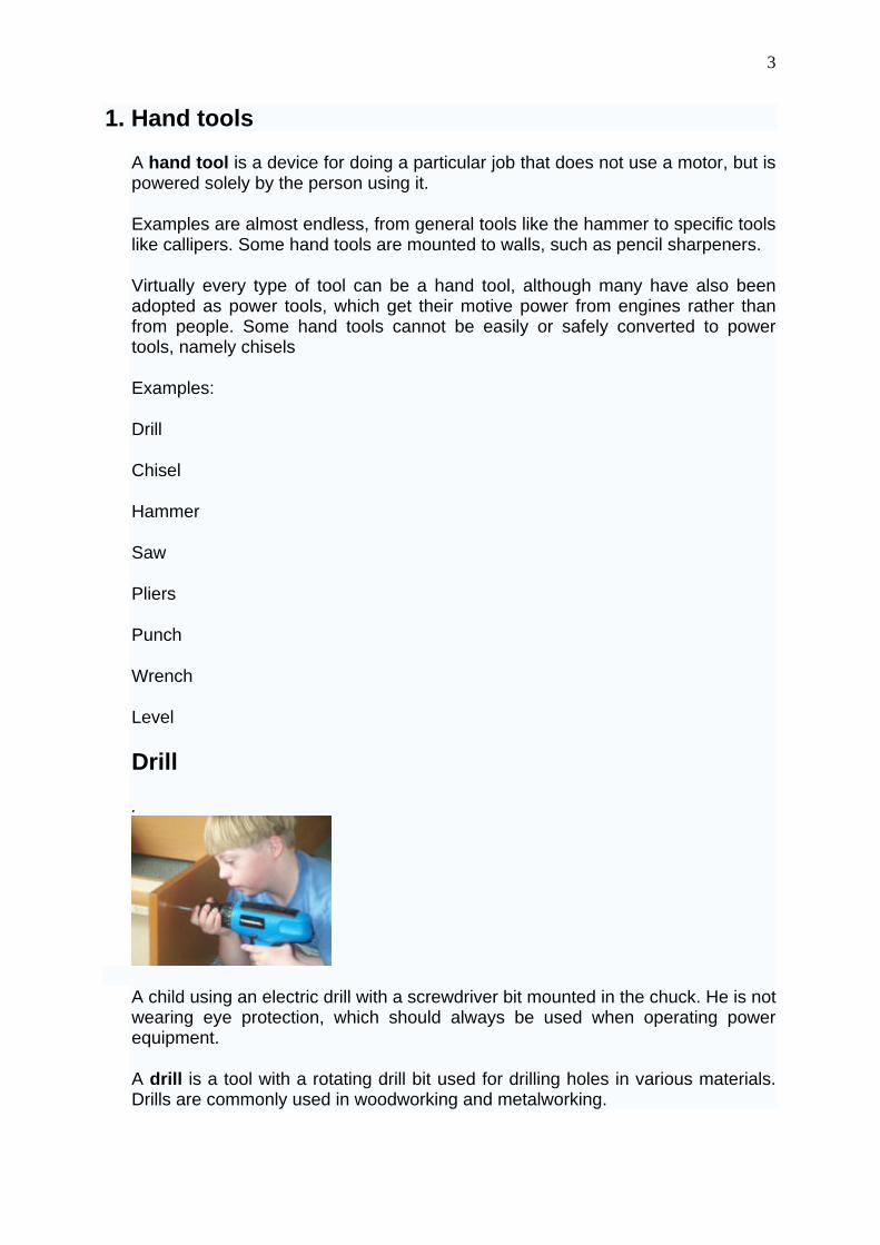
A child using an electric drill with a screwdriver bit mounted in the chuck. He is not wearing eye protection, which should always be used when operating power equipment.
A drill is a tool with a rotating drill bit used for drilling holes in various materials. Drills are commonly used in woodworking and metalworking.
4
The drill bit is gripped by a chuck at one end of the drill, and is pressed against the target material and rotated. The tip of the drill bit does the work of cutting into the target material, slicing off thin shavings (twist drills or auger bits) or grinding off small particles (oil drilling).
Introduction
The earliest drills were probably bow drills. The invention of the electrical drill is credited to Mr. Arthur James Arnot[1], in 1889, at Melbourne, Australia. Wilhelm Fein[2] invented the portable electric drill in 1895, at Stuttgart, Germany. In 1917, Black & Decker patented a trigger-like switch mounted on a pistol-grip handle.[3]
Types
There are many types of drills; some powered manually and others using electricity or compressed air as the motive power. Drills with a percussive action (such as hammer drills, jackhammers or pneumatic drills) are usually used in hard materials such as masonry or rock. As well, drilling rigs are used to bore holes in the earth to obtain water or oil. An oil well, water well, or holes for geothermal heating are created with large drill rigs up to a hundred feet high. Some types of hand-held drills are also used to drive screws.
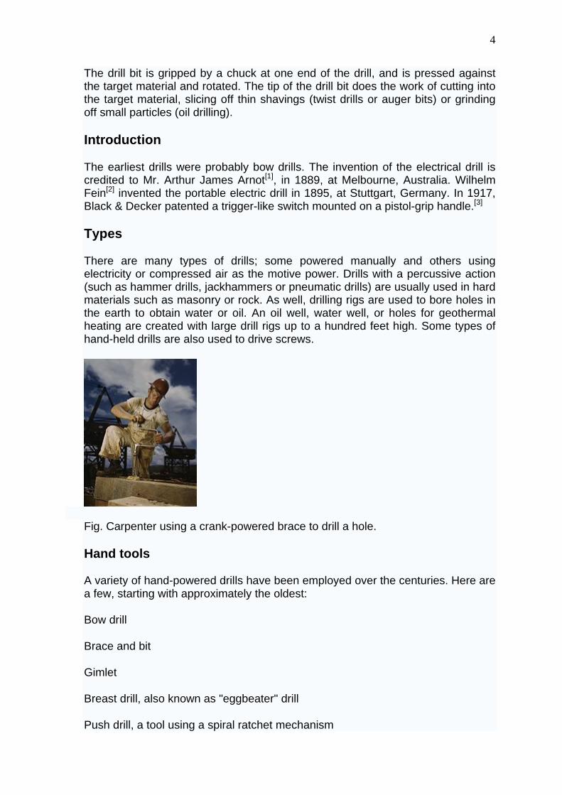
Fig. Carpenter using a crank-powered brace to drill a hole.
Hand tools
A variety of hand-powered drills have been employed over the centuries. Here are a few, starting with approximately the oldest:
Bow drill
Brace and bit
Gimlet
Breast drill, also known as "eggbeater" drill
Push drill, a tool using a spiral ratchet mechanism
5
Pin chuck, a small hand-held jewellers drill
Hammer Drill
The hammer drill is similar to a standard electric drill, with the exception that it is provided with a hammer action for drilling masonry. The hammer action may be engaged or disengaged as required.
Rotary hammer drill
The rotary hammer drill (also known as roto hammer drill or masonry drill) is an electric drill type dedicated to drilling holes in masonry. The rotary hammer drill is a percussion drill that uses a weight to create the impact force on the masonry bit. Generally, the drill chuck of the rotary hammer drill is designed to hold SDS drill bits. Some styles of this drill are intended for masonry drilling only and the hammer action cannot be disengaged. Other styles allow the drill to be used without the hammer action for normal drilling.
Cordless drills
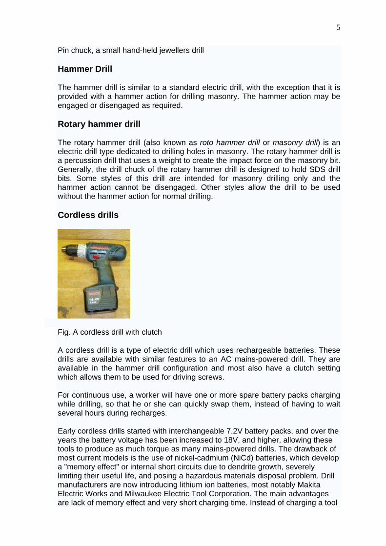
Fig. A cordless drill with clutch
A cordless drill is a type of electric drill which uses rechargeable batteries. These drills are available with similar features to an AC mains-powered drill. They are available in the hammer drill configuration and most also have a clutch setting which allows them to be used for driving screws.
For continuous use, a worker will have one or more spare battery packs charging while drilling, so that he or she can quickly swap them, instead of having to wait several hours during recharges.
Early cordless drills started with interchangeable 7.2V battery packs, and over the years the battery voltage has been increased to 18V, and higher, allowing these tools to produce as much torque as many mains-powered drills. The drawback of most current models is the use of nickel-cadmium (NiCd) batteries, which develop a "memory effect" or internal short circuits due to dendrite growth, severely limiting their useful life, and posing a hazardous materials disposal problem. Drill manufacturers are now introducing lithium ion batteries, most notably Makita Electric Works and Milwaukee Electric Tool Corporation. The main advantages are lack of memory effect and very short charging time. Instead of charging a tool
6
for an hour to get 20 minutes of use, 20 minutes of charge can run the tool for an hour. Lithium-ion batteries also have a constant discharge rate. The power output remains constant until the battery is depleted, something that nickel-cadmium batteries also lack, and which makes the tool much more versatile. Lithium-ion batteries also hold a charge for a significantly longer time than nickel-cadmium batteries, about 2 years if not used, vs. around 4 months for a nickel-cadmium battery.
Drill press
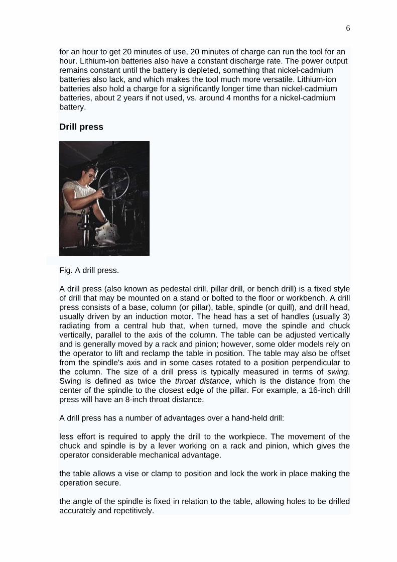
Fig. A drill press.
A drill press (also known as pedestal drill, pillar drill, or bench drill) is a fixed style of drill that may be mounted on a stand or bolted to the floor or workbench. A drill press consists of a base, column (or pillar), table, spindle (or quill), and drill head, usually driven by an induction motor. The head has a set of handles (usually 3) radiating from a central hub that, when turned, move the spindle and chuck vertically, parallel to the axis of the column. The table can be adjusted vertically and is generally moved by a rack and pinion; however, some older models rely on the operator to lift and reclamp the table in position. The table may also be offset from the spindle's axis and in some cases rotated to a position perpendicular to the column. The size of a drill press is typically measured in terms of swing. Swing is defined as twice the throat distance, which is the distance from the center of the spindle to the closest edge of the pillar. For example, a 16-inch drill press will have an 8-inch throat distance.
A drill press has a number of advantages over a hand-held drill:
less effort is required to apply the drill to the workpiece. The movement of the chuck and spindle is by a lever working on a rack and pinion, which gives the operator considerable mechanical advantage.
the table allows a vise or clamp to position and lock the work in place making the operation secure.
the angle of the spindle is fixed in relation to the table, allowing holes to be drilled accurately and repetitively.
7
Speed change is achieved by manually moving a belt across a stepped pulley arrangement. Some drill presses add a third stepped pulley to increase the speed range. Modern dril presses can, however, use a variable-speed motor in conjunction with the stepped-pulley system; some few older drill presses, though, have a sort of traction-based continuously variable transmission for wide ranges of chuck speeds instead, which can be changed while the machine is running.
Geared head drill
The geared head drill is identical to the drill press in most respects, however they are generally of sturdier construction and often have power feed installed on the quill mechanism, and safety interlocks to disengage the feed on overtravel. The most important difference is the drive mechanism between motor and quill is through a gear train (there are no vee belts to tension) this makes these drills suitable for the larger sizes of drill bits (16 mm or 5/8ths" upwards) which would normally stall in a drill press.
Radial arm drill
A radial arm drill is a geared head drill that can be moved away from its column along an arm that is radiates from the column. These drills are used for larger work where a geared head drill would be limited by its reach, the arm can swivel around the column so that any point on the surface of the table can be reached without moving the work piece. The size of work that these drills can handle is considerable as the arm can swivel out of the tables area allowing an overhead crane to place the workpiece on the fixed table. Vices may be used with these machines but the work is generally bolted to the table or a fixture
Mill drill
Mill drills are a lighter alternative to a milling machine. They combine a drill press (belt driven) with the X/Y coordinate abilities of the milling machine's table and a locking collet that ensures that the cutting tool will not fall from the spindle when lateral forces are experienced against the bit. Although they are light in construction, they have the advantages of being space-saving and versatile as well as being suitable for light machining that may otherwise not be affordable.
Chisel
8
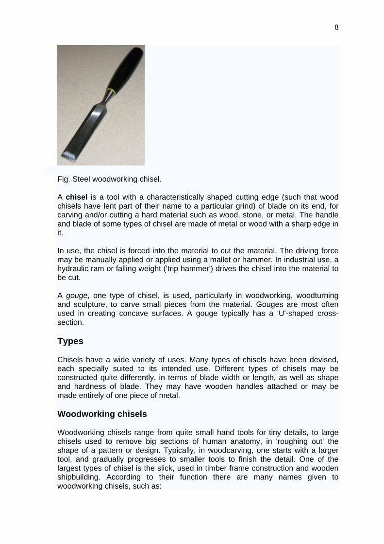
Fig. Steel woodworking chisel.
A chisel is a tool with a characteristically shaped cutting edge (such that wood chisels have lent part of their name to a particular grind) of blade on its end, for carving and/or cutting a hard material such as wood, stone, or metal. The handle and blade of some types of chisel are made of metal or wood with a sharp edge in it.
In use, the chisel is forced into the material to cut the material. The driving force may be manually applied or applied using a mallet or hammer. In industrial use, a hydraulic ram or falling weight ('trip hammer') drives the chisel into the material to be cut.
A gouge, one type of chisel, is used, particularly in woodworking, woodturning and sculpture, to carve small pieces from the material. Gouges are most often used in creating concave surfaces. A gouge typically has a 'U'-shaped cross-section.
Types
Chisels have a wide variety of uses. Many types of chisels have been devised, each specially suited to its intended use. Different types of chisels may be constructed quite differently, in terms of blade width or length, as well as shape and hardness of blade. They may have wooden handles attached or may be made entirely of one piece of metal.
Woodworking chisels
Woodworking chisels range from quite small hand tools for tiny details, to large chisels used to remove big sections of human anatomy, in 'roughing out' the shape of a pattern or design. Typically, in woodcarving, one starts with a larger tool, and gradually progresses to smaller tools to finish the detail. One of the largest types of chisel is the slick, used in timber frame construction and wooden shipbuilding. According to their function there are many names given to woodworking chisels, such as:
9
butt chisel: short chisel with beveled sides and straight edge for creating joints.
carving chisels: used for intricate designs and sculpting; cutting edges are many; such as gouge, skew, parting, straight, paring, and V-groove.
corner chisel: resembles a punch and has an L-shaped cutting edge. Cleans out square holes, mortises and corners with 90 degree angles.
flooring chisel: cuts and lifts flooring materials for removal and repair; ideal for tongue-and-groove flooring.
framing chisel: usually used with mallet; similar to a butt chisel, except it has a longer, slightly flexible blade.
framing slick: a large chisel driven by manual pressure, never struck.
mortise chisel: thick, rigid blade with straight cutting edge and square sides to make mortises and similar joints.
paring chisel: has a long blade which is ideal for cleaning grooves and accessing tight spaces.
skew chisel: has a 60 degree cutting angle and is used for trimming and finishing.
Lathe tools
A lathe tool can be a woodworking chisel designed to cut wood as it is spun on a lathe. These tools have longer handles for more leverage, needed to counteract the tendency of the tool to react to the downward force of the spinning wood being cut or carved. In addition, the angle and method of sharpening is different, a secondary bevel would not be ground on the tool.
Metalworking chisels
Chisels used in metal work can be divided into two main categories, hot chisels, and cold chisels. A hot chisel is used to cut metal that has been heated in a forge to soften the metal.
Cold chisel
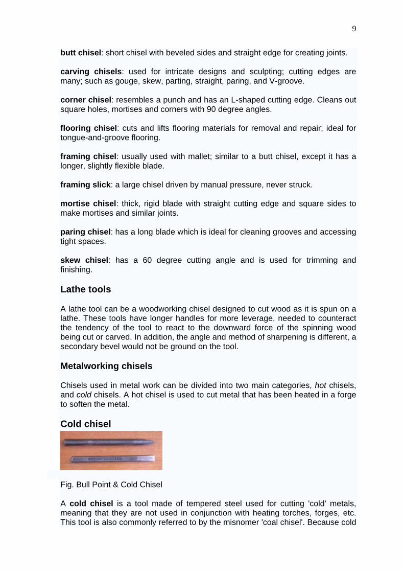
Fig. Bull Point & Cold Chisel
A cold chisel is a tool made of tempered steel used for cutting 'cold' metals, meaning that they are not used in conjunction with heating torches, forges, etc. This tool is also commonly referred to by the misnomer 'coal chisel'. Because cold
10
chisels are used to form metal, they have a less-acute angle to the sharp portion of the blade than a woodworking chisel. This gives the cutting edge greater strength at the expense of sharpness.
Cold chisels come in a variety of sizes, from fine engraving tools that are tapped with very light hammers, to massive tools that are driven with sledgehammers.
Hardy chisel
A hardy chisel is a type of hot chisel with a square shank, which is held in place with the cutting edge facing upwards by placing it in an anvil's Hardy hole. The hot workpiece cut is then placed over the hardy, and struck with a hammer. The hammer drives the chisel into the hot metal, allowing it to be snapped off with a pair of tongs.
Stone chisels
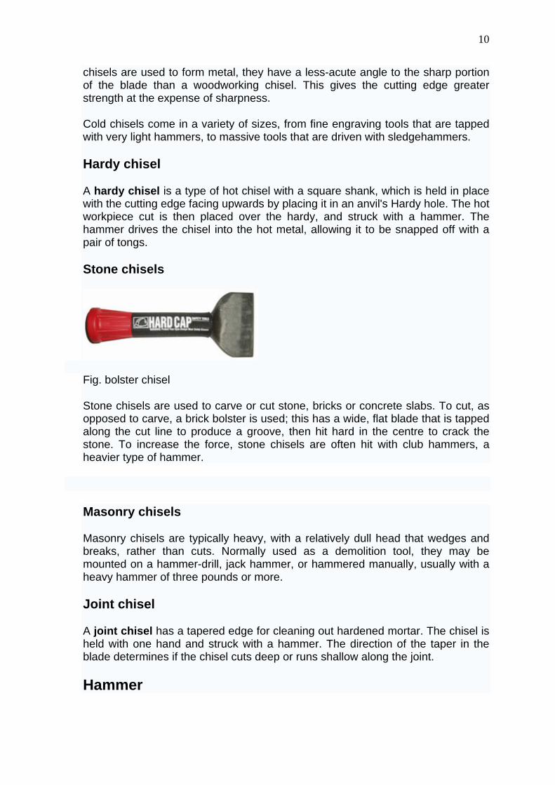
Fig. bolster chisel
Stone chisels are used to carve or cut stone, bricks or concrete slabs. To cut, as opposed to carve, a brick bolster is used; this has a wide, flat blade that is tapped along the cut line to produce a groove, then hit hard in the centre to crack the stone. To increase the force, stone chisels are often hit with club hammers, a heavier type of hammer.
Masonry chisels
Masonry chisels are typically heavy, with a relatively dull head that wedges and breaks, rather than cuts. Normally used as a demolition tool, they may be mounted on a hammer-drill, jack hammer, or hammered manually, usually with a heavy hammer of three pounds or more.
Joint chisel
A joint chisel has a tapered edge for cleaning out hardened mortar. The chisel is held with one hand and struck with a hammer. The direction of the taper in the blade determines if the chisel cuts deep or runs shallow along the joint.
Hammer
11
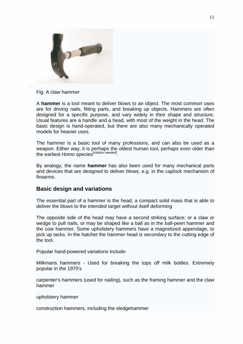
Fig. A claw hammer
A hammer is a tool meant to deliver blows to an object. The most common uses are for driving nails, fitting parts, and breaking up objects. Hammers are often designed for a specific purpose, and vary widely in their shape and structure. Usual features are a handle and a head, with most of the weight in the head. The basic design is hand-operated, but there are also many mechanically operated models for heavier uses.
The hammer is a basic tool of many professions, and can also be used as a weapon. Either way, it is perhaps the oldest human tool, perhaps even older than the earliest Homo species[citation needed].
By analogy, the name hammer has also been used for many mechanical parts and devices that are designed to deliver blows, e.g. in the caplock mechanism of firearms.
Basic design and variations
The essential part of a hammer is the head, a compact solid mass that is able to deliver the blows to the intended target without itself deforming
The opposite side of the head may have a second striking surface; or a claw or wedge to pull nails, or may be shaped like a ball as in the ball-peen hammer and the cow hammer. Some upholstery hammers have a magnetized appendage, to pick up tacks. In the hatchet the hammer head is secondary to the cutting edge of the tool.
Popular hand-powered variations include-
Milkmans hammers - Used for breaking the tops off milk bottles. Extremely popular in the 1970's
carpenter's hammers (used for nailing), such as the framing hammer and the claw hammer
upholstery hammer
construction hammers, including the sledgehammer
12
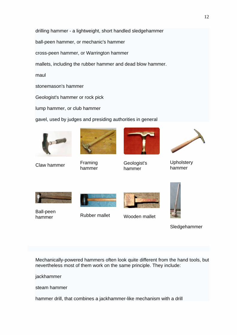
drilling hammer - a lightweight, short handled sledgehammer
ball-peen hammer, or mechanic's hammer
cross-peen hammer, or Warrington hammer
mallets, including the rubber hammer and dead blow hammer.
maul
stonemason's hammer
Geologist's hammer or rock pick
lump hammer, or club hammer
gavel, used by judges and presiding authorities in general
Claw hammer
Framing hammer
Geologist's hammer
Upholstery hammer
Ball-peen hammer
Rubber mallet
Wooden mallet
Sledgehammer
Mechanically-powered hammers often look quite different from the hand tools, but nevertheless most of them work on the same principle. They include:
jackhammer
steam hammer
hammer drill, that combines a jackhammer-like mechanism with a drill
13
In professional framing carpentry, the hammer has almost been completely replaced by the nail gun. In professional upholstery, its chief competitor is the staple gun.
The physics of hammering
Hammer as a force amplifier
A hammer is basically a force amplifier, that works by converting mechanical work into kinetic energy and back.
In the swing that precedes each blow, a certain amount of kinetic energy gets stored in the hammer's head, equal to the length D of the swing times the force f produced by the muscles of the arm and by gravity. When the hammer strikes, the head gets stopped by an opposite force coming from the target; which is equal and opposite to the force applied by the head to the target. If the target is a hard and heavy object, or if it is resting on some sort of anvil, the head can travel only a very short distance d before stopping. Since the stopping force F times that distance must be equal to the head's kinetic energy, it follows that F will be much greater than the original driving force f—roughly, by a factor D/d. In this way, great strength is not needed to produce a force strong enough to bend steel, or crack the hardest stone.
Effect of the head's mass
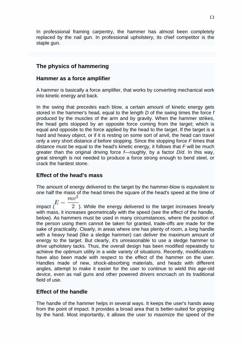
The amount of energy delivered to the target by the hammer-blow is equivalent to one half the mass of the head times the square of the head's speed at the time of
impact ( ). While the energy delivered to the target increases linearly with mass, it increases geometrically with the speed (see the effect of the handle, below). As hammers must be used in many circumstances, where the position of the person using them cannot be taken for granted, trade-offs are made for the sake of practicality. Clearly, in areas where one has plenty of room, a long handle with a heavy head (like a sledge hammer) can deliver the maximum amount of energy to the target. But clearly, it's unreasonable to use a sledge hammer to drive upholstery tacks. Thus, the overall design has been modified repeatedly to achieve the optimum utility in a wide variety of situations. Recently, modifications have also been made with respect to the effect of the hammer on the user. Handles made of new, shock-absorbing materials, and heads with different angles, attempt to make it easier for the user to continue to wield this age-old device, even as nail guns and other powered drivers encroach on its traditional field of use.
Effect of the handle
The handle of the hammer helps in several ways. It keeps the user's hands away from the point of impact. It provides a broad area that is better-suited for gripping by the hand. Most importantly, it allows the user to maximize the speed of the
14
head on each blow. The primary constraint on additional handle length is the lack of space in which to swing the hammer. This is why sledge hammers, largely used in open spaces, can have handles that are much longer than a standard carpenter's hammer. The second most important constraint is more subtle. Even without considering the effects of fatigue, the longer the handle, the harder it is to guide the head of the hammer to its target at full speed. Most designs are a compromise between practicality and energy efficiency. Too long a handle: the hammer is inefficient because it delivers force to the wrong place, off-target. Too short a handle: the hammer is inefficient because it doesn't deliver enough force, requiring more blows to complete a given task.
War hammers
The concept of putting a handle on a weight to make it more convenient to use may well have led to the very first weapons ever invented. The club is basically a variant of a hammer. In the Middle Ages, the war hammer became popular when edged weapons could no longer easily penetrate some forms of armour.
Symbolic hammers
The hammer is associated with West Ham United, who are nicknamed 'The Hammers' and have a symbol of two crossed hammers on the team crest. The origin of this goes back to the club's beginning in the 19th Century, when the Thames Ironworks company football team turned professional in 1895, and became renamed as West Ham United.
The hammer, being one of the most used tools by Homo Sapiens, has been used very much in symbols and arms. In the middle ages it was used often in blacksmith guild logos, as well as in many family symbols. The most recognised symbol with a hammer in it is the Hammer and Sickle, which was the symbol of the former Soviet Union. The hammer in this symbol represents the industrial working class (and the sickle the agricultural working class). The hammer is used in some coat of arms in (former) socialist (or pseudo socialist) countries like East Germany.
In Norse Mythology, Thor, the god of thunder and lightning, wields a hammer named Mjolnir. Many artifacts of decorative hammers have been found leading many modern practitioners of this religion to often wear reproductions as a sign of their faith.
In the 1982 film Pink Floyd The Wall, a circular logo featuring two crossed hammers was used on armbands, flags, and banners during the fascist rally scene. These hammers were also featured in the famous "marching hammers" animation loop and the video for "Another Brick in the Wall (Part II)".
The song If I Had a Hammer has been a top ten hit and was considered an anthem of the Civil Rights Movement. It has been recorded by many artists, including Peter, Paul, and Mary, Trini Lopez, and Leonard Nimoy. The song begins:
If I had a hammer I'd hammer in the morning
15
I'd hammer in the evening all over this land I'd hammer out danger, I'd hammer out warning I'd hammer out love between my brothers and my sisters All over this land
In ultimate frisbee, the hammer is a commonly used overhead throw that is thrown vertically and turns over to land upside down horizontally.
Saw .
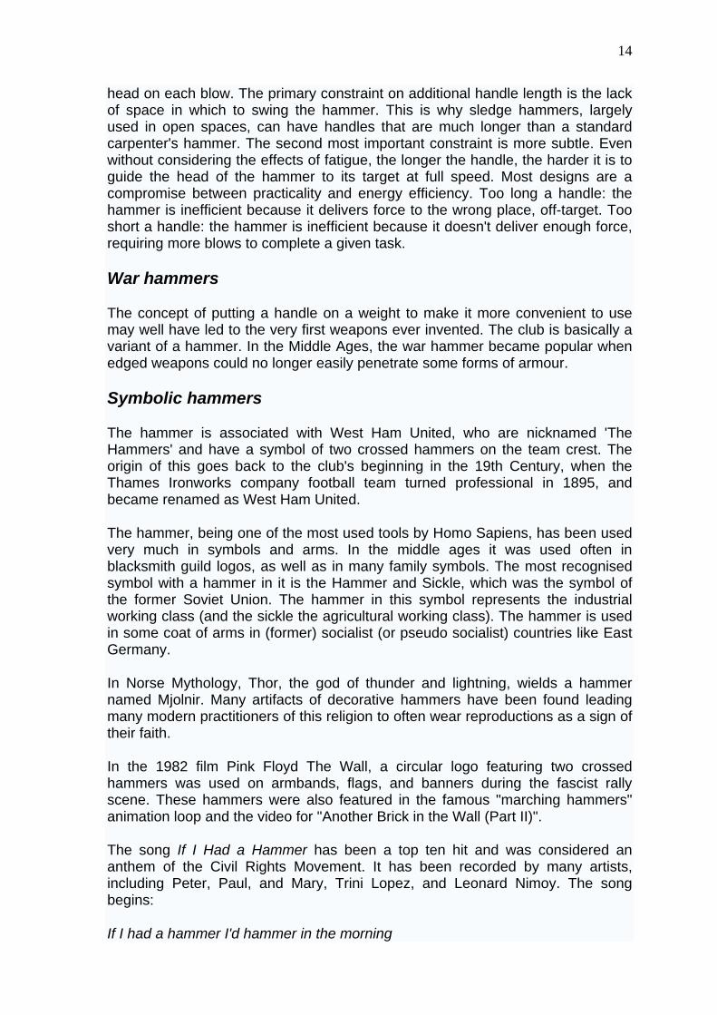
Fig. Portable saw
A saw is a tool for cutting wood or other material, consisting of a serrated blade (a blade with the cutting edge dentated or toothed) and worked either by hand or by steam, water, electric or other power. The teeth of the saw are each bent to specific angle and this angle is called "set". The set of a tooth is dependent on the kind of cut the saw will be making. For example a "rip saw" has a tooth set that is similar to the angle used on a chisel. The idea is to have the teeth rip or tear the fibers of the wood apart.
The saw can also be used, more uncommonly, for playing music.
According to Chinese tradition, the saw was invented by Lu Ban. In Greek mythology, Perdix, the nephew of Daedalos, invented the saw. In reality, metal saws likely evolved from Neolithic stone tools.
Saw terminology
16
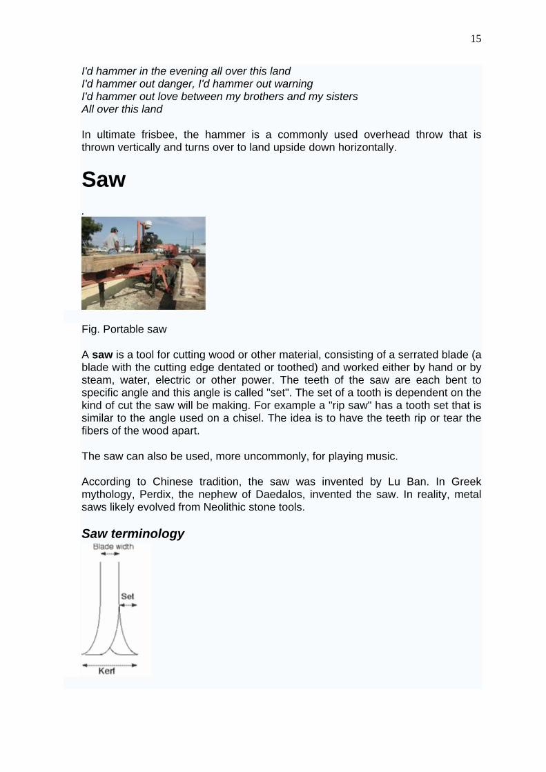
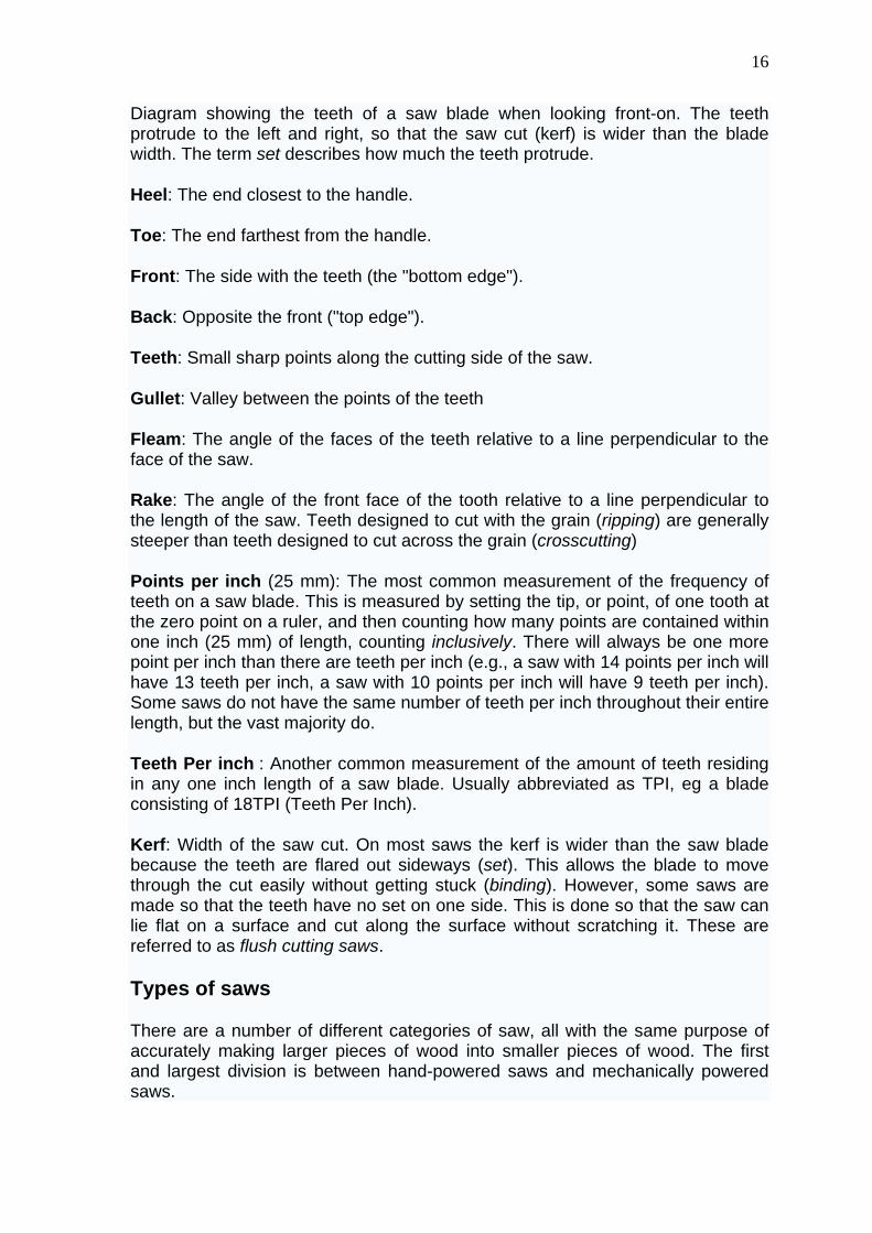
Diagram showing the teeth of a saw blade when looking front-on. The teeth protrude to the left and right, so that the saw cut (kerf) is wider than the blade width. The term set describes how much the teeth protrude.
Heel: The end closest to the handle.
Toe: The end farthest from the handle.
Front: The side with the teeth (the "bottom edge").
Back: Opposite the front ("top edge").
Teeth: Small sharp points along the cutting side of the saw.
Gullet: Valley between the points of the teeth
Fleam: The angle of the faces of the teeth relative to a line perpendicular to the face of the saw.
Rake: The angle of the front face of the tooth relative to a line perpendicular to the length of the saw. Teeth designed to cut with the grain (ripping) are generally steeper than teeth designed to cut across the grain (crosscutting)
Points per inch (25 mm): The most common measurement of the frequency of teeth on a saw blade. This is measured by setting the tip, or point, of one tooth at the zero point on a ruler, and then counting how many points are contained within one inch (25 mm) of length, counting inclusively. There will always be one more point per inch than there are teeth per inch (e.g., a saw with 14 points per inch will have 13 teeth per inch, a saw with 10 points per inch will have 9 teeth per inch). Some saws do not have the same number of teeth per inch throughout their entire length, but the vast majority do.
Teeth Per inch : Another common measurement of the amount of teeth residing in any one inch length of a saw blade. Usually abbreviated as TPI, eg a blade consisting of 18TPI (Teeth Per Inch).
Kerf: Width of the saw cut. On most saws the kerf is wider than the saw blade because the teeth are flared out sideways (set). This allows the blade to move through the cut easily without getting stuck (binding). However, some saws are made so that the teeth have no set on one side. This is done so that the saw can lie flat on a surface and cut along the surface without scratching it. These are referred to as flush cutting saws.
Types of saws
There are a number of different categories of saw, all with the same purpose of accurately making larger pieces of wood into smaller pieces of wood. The first and largest division is between hand-powered saws and mechanically powered saws.
17
Note that the names used for different types of saw are by no means universal. Names have changed over time and even today the same name may be used for different kinds of saws in different parts of the world or by different manufacturers. Also, the same saw may be referred to by different names.
Hand saws
Hand-powered saws fall into three divisions, which are defined by the way they hold the blade stiff (a requirement to get an even, clean cut).
A Hand saw uses either simply a blade thick enough to be stiff, or cuts on the pull stoke which reduces the stiffness requirement. This division includes the following specific types of saws:
Crosscut saw, for making cuts perpendicular to the grain
Rip saw, for cutting along the grain
Hand saw, saws operated by hand as opposed to power saws
Floorboard saw, with curved blade
Japanese saw, hand saws that cut on the pull stroke with straight handles
Keyhole saw or padsaw or compass saw, with narrow pointed blade
Two-man saw, for cutting large logs or trees
Plywood saw, fine-toothed blade to reduce tearing of plywood
Veneer saw, two edged saw with fine teeth used to cut veneer
Although their use is dwindling the jigsaw and sabre saw (unpowered tools) may also refer to blade style saws.
Back saws
The second category of hand saws keep a thinner blade stiff by reinforcing it with a steel or brass back. Back saws are differentiated by length of blade. While this list is not definitive, they are generally named, from longest to shortest: Mitre Saw, Carcase Saw, Tenon saw, and Dovetail saw. These saws also have a handle that is vertical in relation to the blade. A saw with a straight handle that extends from the top back of the blade is referred to as a Gent's saw. Finally, some Dozuki saws, which are an Eastern-style (cut on the pull stroke)saw have backs and are classified as back-saws.
One type of hand powered Miter saw (makes precisely angled cross cuts) uses a backsaw.
18
Mechanically powered saws
Mechanically powered saws mechanically move the teeth past the wood while the saw itself is held stationary. This is accomplished in one of three ways: the teeth are along the perimeter of a flat, circular blade; the blade reciprocates up and down rapidly; or the teeth are along one edge of a continuous band. They are more specifically differentiated as follows:
Circular blade saws
Circular saw, machine-driven for industrial sawing of log and beams, typically found in sawmills - also name given to smaller hand-held saws
Table saw, circular blade rises through a slot in a table. It is the most common piece of stationary woodworking equipment. The smaller direct-drive versions that can be set on a workbench are called workbench saws. Smaller belt-driven ones generally set on steel legs are often called Contractor's Saws. The heavier, more precise and more powerful, often driven by multiple belts, with an enclosed base stand as an integral part of the saw are called Cabinet saws. A relatively new version, called a hybrid saw, has the lighter weight mechanism of a Contractor saw but with an enclosed base like the Cabinet saw.
Radial arm saw, versatile machine used mainly for cross-cutting where the blade is pulled on a guide arm through a piece of wood held stationary on the saw's table
Rotary saw, for making accurate cuts without the need for a pilot hole in wallboard, plywood, and other thin materials, also called a spiral cut saw or a "RotoZip". The latter is a trademark owned by Bosch Tool Corp. who pioneered this type of saw - design is similar to a small wood router, bits are similar to a twist drill, some cut on the upward twist, some cut downwards
Electric miter saw, (also called chop saw, cut-off saw or power miter box) – for making accurate cross cuts and miter cuts. The basic model has its circular blade fixed at a 90° angle to the vertical, a compound miter saw's blade can be adjusted to other angles. A sliding compound miter saw has a blade which can be pulled through the work similar to the action of a radial arm saw, which gives a greater capacity for cutting wider workpieces.
Concrete saw, usually powered by an internal combustion engine and used with a Diamond Blade to cut concrete or asphalt pavement.
Reciprocating blade saws
Jigsaw or saber saw (mainly US), narrow blade for cutting irregular shapes, typically held in one hand with the barrel perpendicular to the saw blade. Historically, the term jigsaw was also commonly used for what is now usually called a scroll saw.
19
Reciprocating saw or sabre saw (mainly UK and Australia), action similar to a jigsaw, but much larger, more powerful and with a longer stroke with the blade parallel to the barrel. Normally held in both hands, useful for demolition work or for cutting pipe. Sometimes powered by compressed air.
Scroll saw, saw for making intricate curved cuts (scrolls), the first of which were pedal powered. Traditionally called a jigsaw.
Dragsaw, internal combustion powered saw used for bucking logs before the advent of the chainsaw.
Sternal saw, used in surgery to open a patient's sternum.
Continuous band
Band saw, with motor-driven continuous band
Chainsaw, motor-driven, for felling trees
Types of saw blades and the cuts they make
Blade teeth are of two general types: Tool steel or carbide. Carbide is harder and holds a sharp edge much longer.
Crosscut In woodworking, a cut made at (or near) a right angle to the direction of the grain of the workpiece. A crosscut saw is used to make this type of cut. Rip cut In woodworking, a cut made parallel to the direction of the grain of the workpiece. A rip saw is used to make this type of cut. Plytooth A circular saw blade with many small teeth designed for cutting plywood with minimal splintering. Dado blade A special type of circular saw blade used for making wide grooved cuts in wood so the edge of another piece of wood will fit into the groove to make a joint. Dado blades can make different width grooves by addition or removal of chipper blades of various widths between the outer dado blades. This first type is called a stacked dado blade. There is another type of dado blade capable of cutting variable width grooves. An adjustable dado utilizes a moveable locking cam mechanism which causes the blade to wobble sideways more or less. This allows continuously variable groove width from the lower to upper design limits of the dado.
Materials used for saws
There are several materials used in saws, with each of its own specifications.
Brass
20
Mostly used in back saws because of its low price, its flow characteristics that make the material relatively easy to cast, and unlike other types of saw, the forces that take place in back saws are relatively low because of the pulling motion used. Steel Used in almost every existing kind of saw. Because steel is cheap, easy to shape, and very strong, it has the right properties for most kind of saws. Diamond Used only in saws for the really heavy cutting. It is very expensive and comes in two shapes: ropes and circular saws. Mostly used for cutting concrete and other materials with rock-like structures or in softer materials, such as wood, where the precision and high volume of work justifies the expense of diamond-edged cutting tools. Diamond saws are made by combining powder metal with diamond crystals, which are then heated and pressed into a molding to form the diamond segments.
Pliers
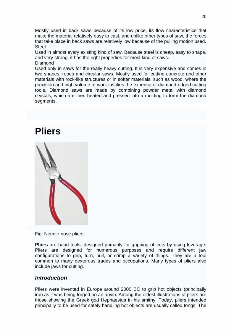
Fig. Needle-nose pliers
Pliers are hand tools, designed primarily for gripping objects by using leverage. Pliers are designed for numerous purposes and require different jaw configurations to grip, turn, pull, or crimp a variety of things. They are a tool common to many dexterous trades and occupations. Many types of pliers also include jaws for cutting.
Introduction
Pliers were invented in Europe around 2000 BC to grip hot objects (principally iron as it was being forged on an anvil). Among the oldest illustrations of pliers are those showing the Greek god Hephaestus in his smithy. Today, pliers intended principally to be used for safely handling hot objects are usually called tongs. The
21
number of different designs of pliers grew with the invention of the different objects which they were used to handle: horse shoes, fasteners, wire, pipes, electrical and electronic components.
Design
The basic design of pliers has changed little since their origins, with the pair of handles, the pivot (often formed by a rivet), and the head section with the gripping jaws or cutting edges forming the three elements. In distinction to a pair of scissors or shears, the plier's jaws always meet each other at one point.
Pliers are an instrument that convert a power grip - the curling of the fingers into the palm of the hand - into a precision grip, directing the power of the hand's grip in a precise fashion on to the object(s) to be gripped. The handles are long relative to the shorter nose of the pliers. The two arms thus act as first class levers with a mechanical advantage, increasing the force applied by the hand's grip and concentrating it on the work piece.
The materials used to make pliers consist mainly of steel alloys with additives such as Vanadium and/or Chromium, to improve alloy strength and prevent corrosion. Often pliers have insulated grips to ensure better handling and prevent electrical conductivity.
Common types
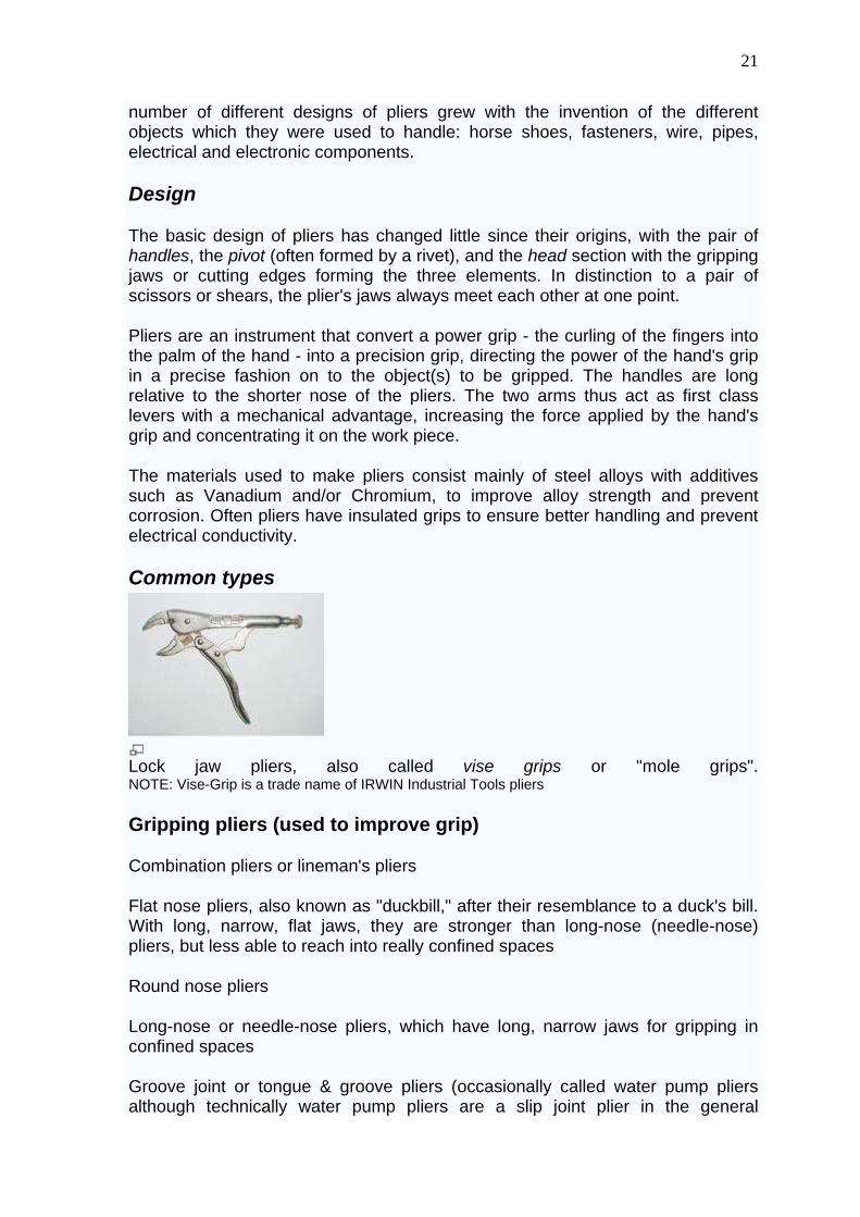
Lock jaw pliers, also called vise grips or "mole grips". NOTE: Vise-Grip is a trade name of IRWIN Industrial Tools pliers
Gripping pliers (used to improve grip)
Combination pliers or lineman's pliers
Flat nose pliers, also known as "duckbill," after their resemblance to a duck's bill. With long, narrow, flat jaws, they are stronger than long-nose (needle-nose) pliers, but less able to reach into really confined spaces
Round nose pliers
Long-nose or needle-nose pliers, which have long, narrow jaws for gripping in confined spaces
Groove joint or tongue & groove pliers (occasionally called water pump pliers although technically water pump pliers are a slip joint plier in the general
22
configuration of groove joint pliers; or referred to by the name of a well-known manufacturer, Channellock) - with adjustable jaw sizes, which are designed to grip various sizes of round, hexagon, flat or similarly shaped objects
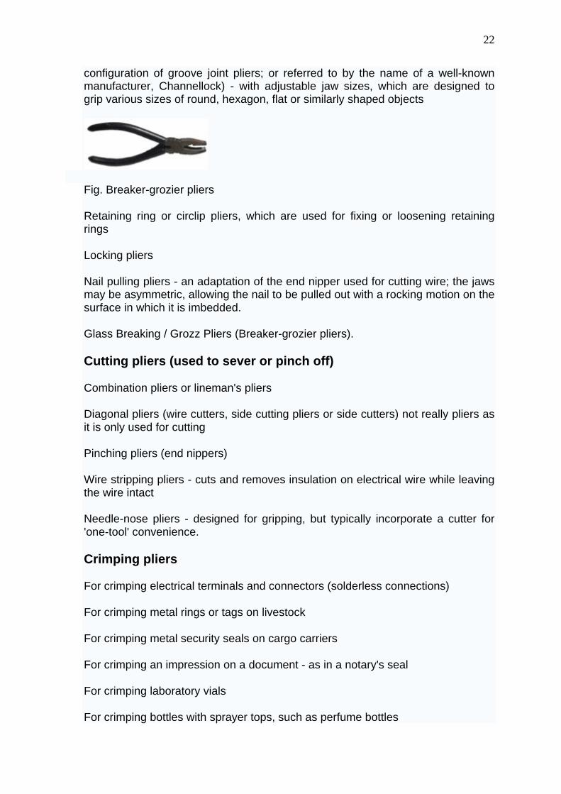
Fig. Breaker-grozier pliers
Retaining ring or circlip pliers, which are used for fixing or loosening retaining rings
Locking pliers
Nail pulling pliers - an adaptation of the end nipper used for cutting wire; the jaws may be asymmetric, allowing the nail to be pulled out with a rocking motion on the surface in which it is imbedded.
Glass Breaking / Grozz Pliers (Breaker-grozier pliers).
Cutting pliers (used to sever or pinch off)
Combination pliers or lineman's pliers
Diagonal pliers (wire cutters, side cutting pliers or side cutters) not really pliers as it is only used for cutting
Pinching pliers (end nippers)
Wire stripping pliers - cuts and removes insulation on electrical wire while leaving the wire intact
Needle-nose pliers - designed for gripping, but typically incorporate a cutter for 'one-tool' convenience.
Crimping pliers
For crimping electrical terminals and connectors (solderless connections)
For crimping metal rings or tags on livestock
For crimping metal security seals on cargo carriers
For crimping an impression on a document - as in a notary's seal
For crimping laboratory vials
For crimping bottles with sprayer tops, such as perfume bottles
23
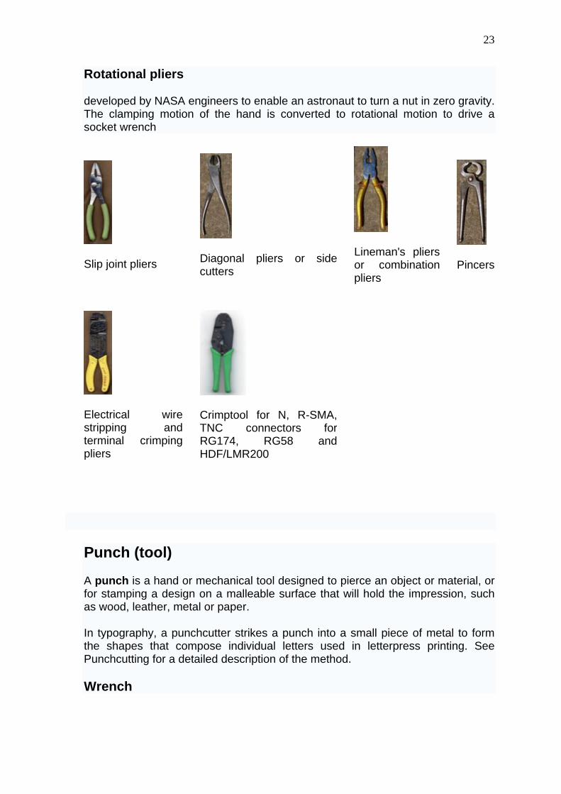
Rotational pliers
developed by NASA engineers to enable an astronaut to turn a nut in zero gravity. The clamping motion of the hand is converted to rotational motion to drive a socket wrench
Slip joint pliers
Diagonal pliers or side cutters
Lineman's pliersor combination pliers
Pincers
Electrical wirestripping andterminal crimpingpliers
Crimptool for N, R-SMA, TNC connectors forRG174, RG58 andHDF/LMR200
Punch (tool)
A punch is a hand or mechanical tool designed to pierce an object or material, or for stamping a design on a malleable surface that will hold the impression, such as wood, leather, metal or paper.
In typography, a punchcutter strikes a punch into a small piece of metal to form the shapes that compose individual letters used in letterpress printing. See Punchcutting for a detailed description of the method.
Wrench
24
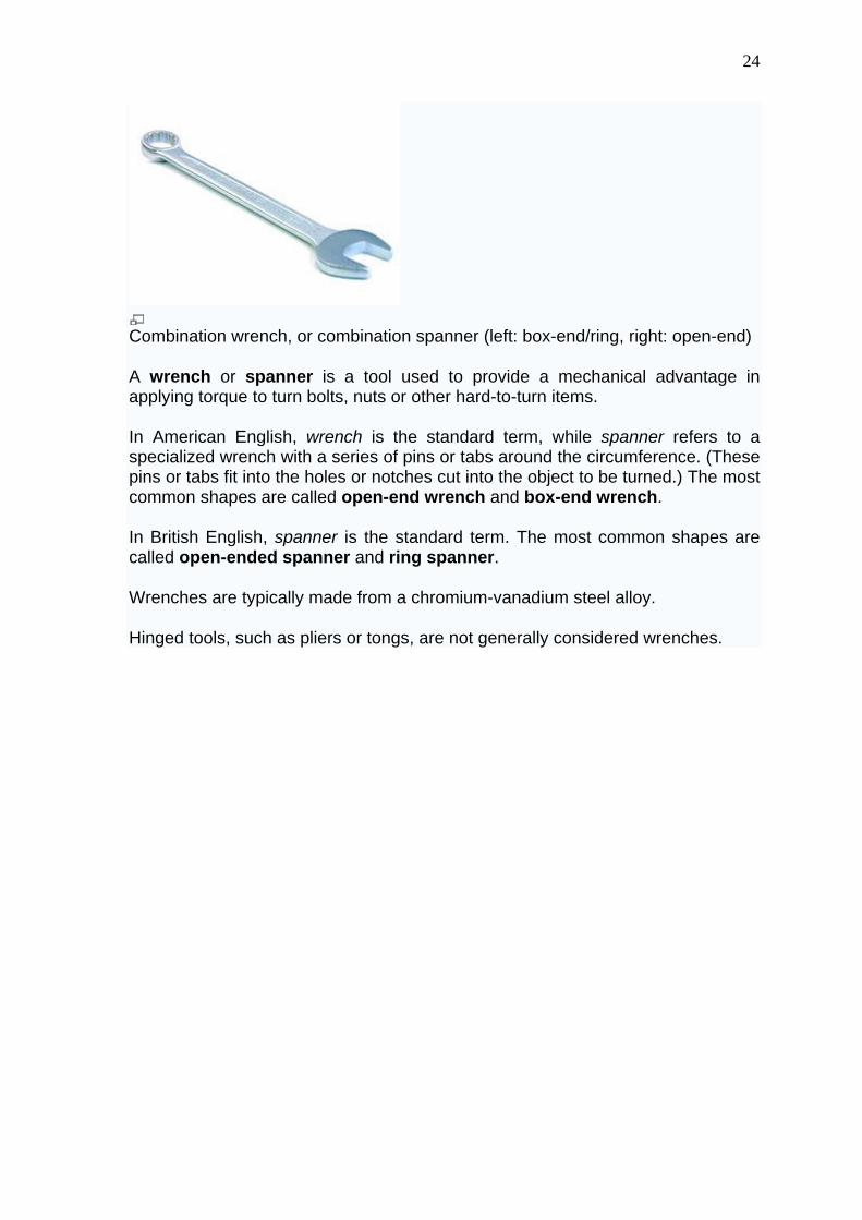
Combination wrench, or combination spanner (left: box-end/ring, right: open-end)
A wrench or spanner is a tool used to provide a mechanical advantage in applying torque to turn bolts, nuts or other hard-to-turn items.
In American English, wrench is the standard term, while spanner refers to a specialized wrench with a series of pins or tabs around the circumference. (These pins or tabs fit into the holes or notches cut into the object to be turned.) The most common shapes are called open-end wrench and box-end wrench.
In British English, spanner is the standard term. The most common shapes are called open-ended spanner and ring spanner.
Wrenches are typically made from a chromium-vanadium steel alloy.
Hinged tools, such as pliers or tongs, are not generally considered wrenches.
25
Common wrenches / spanners
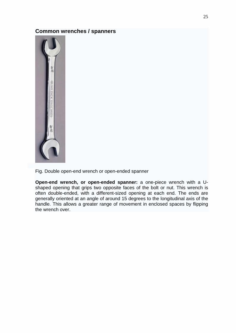
Fig. Double open-end wrench or open-ended spanner
Open-end wrench, or open-ended spanner: a one-piece wrench with a U-shaped opening that grips two opposite faces of the bolt or nut. This wrench is often double-ended, with a different-sized opening at each end. The ends are generally oriented at an angle of around 15 degrees to the longitudinal axis of the handle. This allows a greater range of movement in enclosed spaces by flipping the wrench over.
26
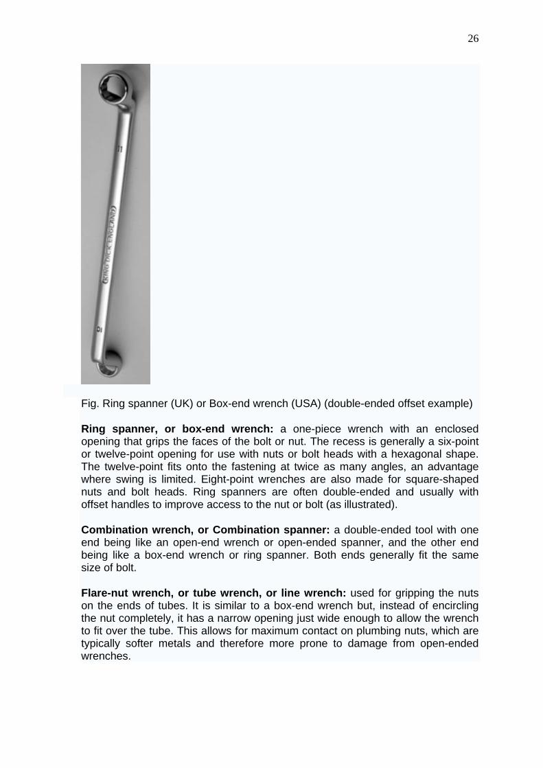
Fig. Ring spanner (UK) or Box-end wrench (USA) (double-ended offset example)
Ring spanner, or box-end wrench: a one-piece wrench with an enclosed opening that grips the faces of the bolt or nut. The recess is generally a six-point or twelve-point opening for use with nuts or bolt heads with a hexagonal shape. The twelve-point fits onto the fastening at twice as many angles, an advantage where swing is limited. Eight-point wrenches are also made for square-shaped nuts and bolt heads. Ring spanners are often double-ended and usually with offset handles to improve access to the nut or bolt (as illustrated).
Combination wrench, or Combination spanner: a double-ended tool with one end being like an open-end wrench or open-ended spanner, and the other end being like a box-end wrench or ring spanner. Both ends generally fit the same size of bolt.
Flare-nut wrench, or tube wrench, or line wrench: used for gripping the nuts on the ends of tubes. It is similar to a box-end wrench but, instead of encircling the nut completely, it has a narrow opening just wide enough to allow the wrench to fit over the tube. This allows for maximum contact on plumbing nuts, which are typically softer metals and therefore more prone to damage from open-ended wrenches.
27
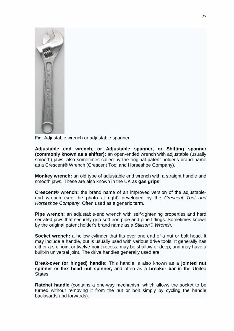
Fig. Adjustable wrench or adjustable spanner
Adjustable end wrench, or Adjustable spanner, or Shifting spanner (commonly known as a shifter): an open-ended wrench with adjustable (usually smooth) jaws, also sometimes called by the original patent holder's brand name as a Crescent® Wrench (Crescent Tool and Horseshoe Company).
Monkey wrench: an old type of adjustable end wrench with a straight handle and smooth jaws. These are also known in the UK as gas grips.
Crescent® wrench: the brand name of an improved version of the adjustable-end wrench (see the photo at right) developed by the Crescent Tool and Horseshoe Company. Often used as a generic term.
Pipe wrench: an adjustable-end wrench with self-tightening properties and hard serrated jaws that securely grip soft iron pipe and pipe fittings. Sometimes known by the original patent holder's brand name as a Stillson® Wrench.
Socket wrench: a hollow cylinder that fits over one end of a nut or bolt head. It may include a handle, but is usually used with various drive tools. It generally has either a six-point or twelve-point recess, may be shallow or deep, and may have a built-in universal joint. The drive handles generally used are:
Break-over (or hinged) handle: This handle is also known as a jointed nut spinner or flex head nut spinner, and often as a breaker bar in the United States.
Ratchet handle (contains a one-way mechanism which allows the socket to be turned without removing it from the nut or bolt simply by cycling the handle backwards and forwards).
28
Speed handle (sometimes called a crank handle or speed brace).
Screwdriver handle (for use of the socket as a nutdriver).
Sockets are often sold as a set containing a collection of sockets of various sizes and associated drive tools; usually including, as a minimum, extensions, a ratchet driver, and a universal joint. Sockets are also used with various power tools.
Crowfoot socket wrench: a type of socket designed to fit some of the same drive handles as the regular socket but non-cylindrical in shape. The ends are the same as those found on the open-end, box-end, or the flare-nut wrenches. These sockets use for use where space restrictions preclude the use of a regular socket. Their principal use is with torque wrenches.
Saltus wrench: similar in concept to a socket wrench. A Saltus wrench features a socket permanently affixed to a handle. Sockets are not interchangeable as with a socket wrench. The socket often rotates around the handle to allow the user to access a fastener from a variety of angles. Commonly a Saltus wrench is part of a double-ended wrench, with an open-end type head on the opposite side from the socket head.
A mole wrench, also known as a mole grip, is not a wrench but a type of self-locking pliers.
A box spanner (UK) is a tube with 6-sided sockets on both ends. It is turned with a short length of rod (tommy bar or T bar) inserted through two holes in the middle of the tube.
Slogging Spanner: A spanner (both open and ring types are available) with a block end to the handle specifically designed for use with a hammer. Typically used to release large nuts and bolts where the shock of the impact is useful in breaking rust or paint.
Other general wrenches / spanners
Wrenches for screws and bolts with internal sockets are generally referred to in the UK as keys, and include:
Hex key wrench, Allen wrench or Allen key: a (usually) L-shaped wrench fabricated from hexagonal wire stock of various sizes, used to turn screw or bolt heads designed with a hexagonal recess to receive the wrench.
Bristol® wrench, or Bristol spline wrench: another wrench designed for internal socket-head screws and bolts. The cross-section resembles a square-toothed gear. Not a common design, it is chiefly used on small set screws.
TORX® wrench: an internal socket-head screw design. The cross-section resembles a star. Commonly used in automobiles, automated equipment, and computer components.
29
Strap wrench or chain wrench: a self-tightening wrench with either a chain or strap of metal, leather, or rubber attached to a handle, used to grip and turn smooth cylindrical objects. In bicycle repair circles it is known as a chain whip and is used to remove and install cassettes on rear hubs.
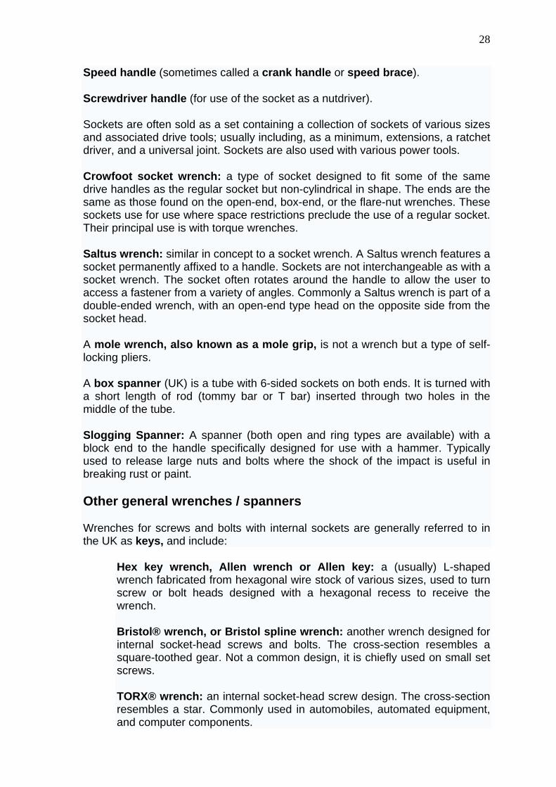
Schematic showing how an alligator wrench allows the user to grip square-headed fasteners of various sizes.
Alligator wrench: a formerly common type of wrench that was popular with mechanics, factory workers, and farmers for maintenance, repair and operations tasks in the days when fasteners often had square rather than hex heads. The wrench's shape suggests the open mouth of an alligator.
Specialized wrenches / spanners
Spoke wrench or spoke key: a wrench with a clearance slot for a wire wheel spoke such as a bicycle wheel and a drive head for the adjustment nipple nut.
Peanut butter wrench or crank (bolt) spanner: a wrench used by cyclists to tighten cranks (wheel nuts), and to scoop out peanut butter from a jar!
Fig. Double handled tap wrench
Tap wrench: a double-handled wrench for turning the square drive on taps used in threading operations (cutting the female threads such as within a nut) or a precision reamer.
Die wrench: A double-handled wrench for turning the dies used in threading operations (cutting the male threads such as on a bolt).
Torque wrench: a socket wrench drive tool that measures the amount of rotational force applied to the socket—this may be indicated visually with a rod or dial or may simply slip when a set torque is exceeded. The torque wrench would also be categorized as a measuring tool.
Drum wrench: a tool commonly used to open bungs on large 55 gallon drums.
30
Lug wrench: a socket wrench used to turn lug nuts on automobile wheels. Commonly known in the UK as a wheel brace.
Plumber wrench: a tool to screw (rotate with force) various pipes during plumbing.
Tuning wrench: a socket wrench used to tune some stringed musical instruments.
Oil-filter wrench: a type of wrench for removing cylindrical oil filters. It may be either a strap-type wrench or a socket.
Sink wrench: a self-tightening wrench mounted at the end of a torque tube with a transverse handle at the opposite end. Used to tighten tubing connections to washstand valves in ceramic sinks—the nuts are often located deep in recesses. The self-tightening head may be flipped over to loosen connections.
Podging Wrench or Podger: A steel erecting tool which consists of a normal wrench at one end and a spike at the other, used for lining up bolt holes. In the U.S. often called a spud wrench.
Golf shoe spike wrench: a T-handle wrench with two pins and clearance for the spike—allows removal and insertion of spikes in shoes.
Head nut wrench: a flat wrench with a circular hole and two inward protruding pins to engage slots in the nut. This type of nut is used on bicycles to secure the front fork pivot bearing to the headpiece of the frame.
Fire hydrant wrench (hose connection): The hose connection has a threaded collar with a protruding pin. From the handle of the wrench an arc has at its end a loop to engage the pin.
Fire hydrant wrench (valve operator): This is a pentagonal (five-sided) box wrench. Avoiding a hex shape for the lug makes the valve tamper-resistant: with the opposite faces nonparallel, unauthorized opening of the hydrant is less likely, because the would-be opener lacks a suitable tool.
Chain wrench: Similar to a pipe wrench, but uses a chain similar to a drive chain, instead of an adjustable jaw. The links of the chain have extended pegs which fit into grooves in the front of the handle, with one end of the chain attached permently to the handle. This is used in situations where pipe wrenches can't maintain a proper grip on an object such as a wet or oily pipe.
Left-handed wrench: A non-existent tool which is often the object of a fool's errand.
Air impact wrench: A compressed air (pneumatic) powered wrench commonly used in car garages and workshops to tighten and remove wheel nuts.
Caliper
31
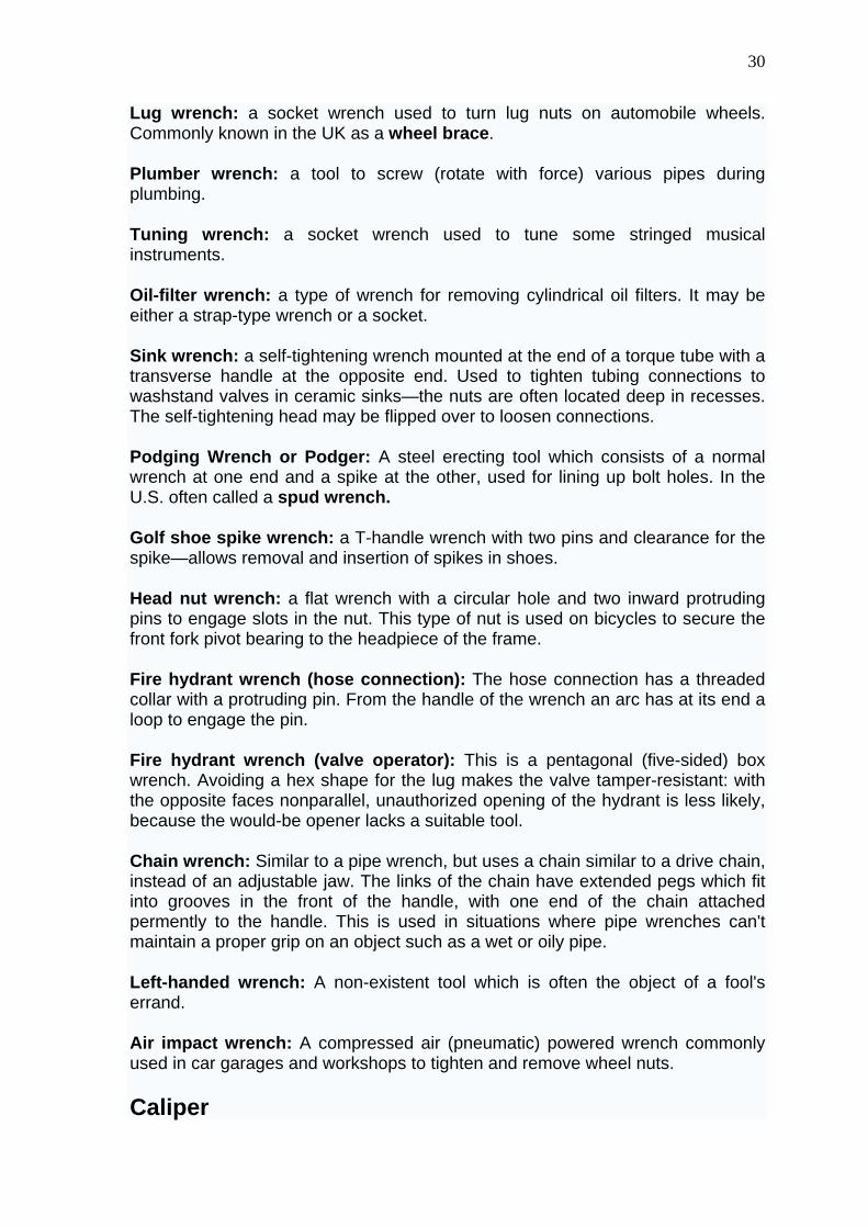
Fig. Digital caliper
A caliper (British spelling also calliper) is a device used to measure the distance between two symmetrically opposing sides. A caliper can be as simple as a compass with inward or outward-facing points. The tips of the caliper are adjusted to fit across the points to be measured, the caliper is then removed and the distance read by measuring between the tips with a measuring tool, such as a ruler.
They are used in the metalworking field of mechanical engineering, handloading, and in woodworking and woodturning.
Types
Inside caliper
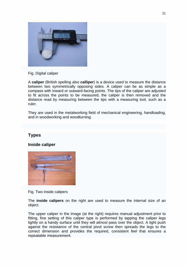
Fig. Two inside calipers
The inside calipers on the right are used to measure the internal size of an object.
The upper caliper in the image (at the right) requires manual adjustment prior to fitting, fine setting of this caliper type is performed by tapping the caliper legs lightly on a handy surface until they will almost pass over the object. A light push against the resistance of the central pivot screw then spreads the legs to the correct dimension and provides the required, consistent feel that ensures a repeatable measurement.
32
The lower caliper in the image has an adjusting screw that permits it to be carefully adjusted without removal of the tool from the workpiece.
Outside caliper
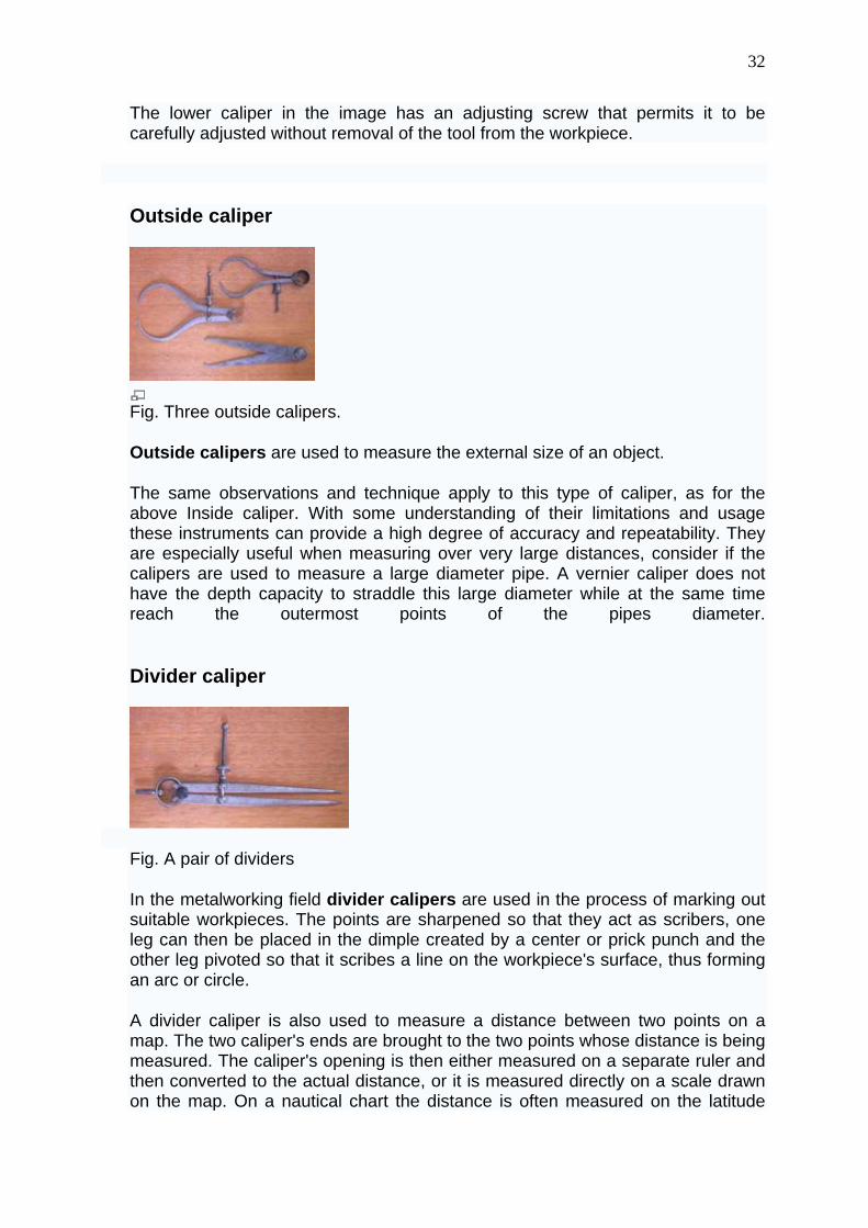
Fig. Three outside calipers.
Outside calipers are used to measure the external size of an object.
The same observations and technique apply to this type of caliper, as for the above Inside caliper. With some understanding of their limitations and usage these instruments can provide a high degree of accuracy and repeatability. They are especially useful when measuring over very large distances, consider if the calipers are used to measure a large diameter pipe. A vernier caliper does not have the depth capacity to straddle this large diameter while at the same time reach the outermost points of the pipes diameter.
Divider caliper
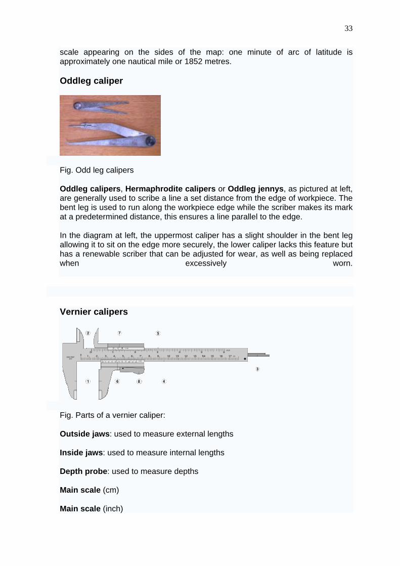
Fig. A pair of dividers
In the metalworking field divider calipers are used in the process of marking out suitable workpieces. The points are sharpened so that they act as scribers, one leg can then be placed in the dimple created by a center or prick punch and the other leg pivoted so that it scribes a line on the workpiece's surface, thus forming an arc or circle.
A divider caliper is also used to measure a distance between two points on a map. The two caliper's ends are brought to the two points whose distance is being measured. The caliper's opening is then either measured on a separate ruler and then converted to the actual distance, or it is measured directly on a scale drawn on the map. On a nautical chart the distance is often measured on the latitude
33
scale appearing on the sides of the map: one minute of arc of latitude is approximately one nautical mile or 1852 metres.
Oddleg caliper
Fig. Odd leg calipers
Oddleg calipers, Hermaphrodite calipers or Oddleg jennys, as pictured at left, are generally used to scribe a line a set distance from the edge of workpiece. The bent leg is used to run along the workpiece edge while the scriber makes its mark at a predetermined distance, this ensures a line parallel to the edge.
In the diagram at left, the uppermost caliper has a slight shoulder in the bent leg allowing it to sit on the edge more securely, the lower caliper lacks this feature but has a renewable scriber that can be adjusted for wear, as well as being replaced when excessively worn.
Vernier calipers
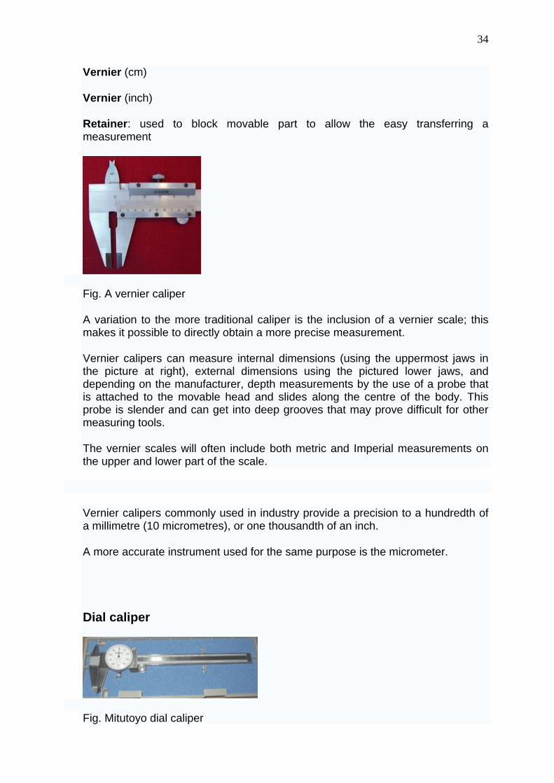
Fig. Parts of a vernier caliper:
Outside jaws: used to measure external lengths
Inside jaws: used to measure internal lengths
Depth probe: used to measure depths
Main scale (cm)
Main scale (inch)
34
Vernier (cm)
Vernier (inch)
Retainer: used to block movable part to allow the easy transferring a measurement
Fig. A vernier caliper
A variation to the more traditional caliper is the inclusion of a vernier scale; this makes it possible to directly obtain a more precise measurement.
Vernier calipers can measure internal dimensions (using the uppermost jaws in the picture at right), external dimensions using the pictured lower jaws, and depending on the manufacturer, depth measurements by the use of a probe that is attached to the movable head and slides along the centre of the body. This probe is slender and can get into deep grooves that may prove difficult for other measuring tools.
The vernier scales will often include both metric and Imperial measurements on the upper and lower part of the scale.
Vernier calipers commonly used in industry provide a precision to a hundredth of a millimetre (10 micrometres), or one thousandth of an inch.
A more accurate instrument used for the same purpose is the micrometer.
Dial caliper
Fig. Mitutoyo dial caliper
35
A further refinement to the vernier caliper is the dial caliper.
In this instrument, a small gear rack drives a pointer on a circular dial. Typically, the pointer rotates once every inch, tenth of an inch, or 10 millimetres, allowing for a direct reading without the need to read a vernier scale (although one still needs to add the basic inches or tens of millimeters value read from the slide of the caliper). The dial is usually arranged to be rotatable beneath the pointer, allowing for "differential" measurements (the measuring of the difference in size between two objects, or the setting of the dial using a master object and subsequently being able to read directly the plus-or-minus variance in size of subsequent objects relative to the master object).
The slide of a dial caliper can usually be locked at a setting using a small lever or screw; this allows simple go/no-go checks of part sizes.
Digital caliper
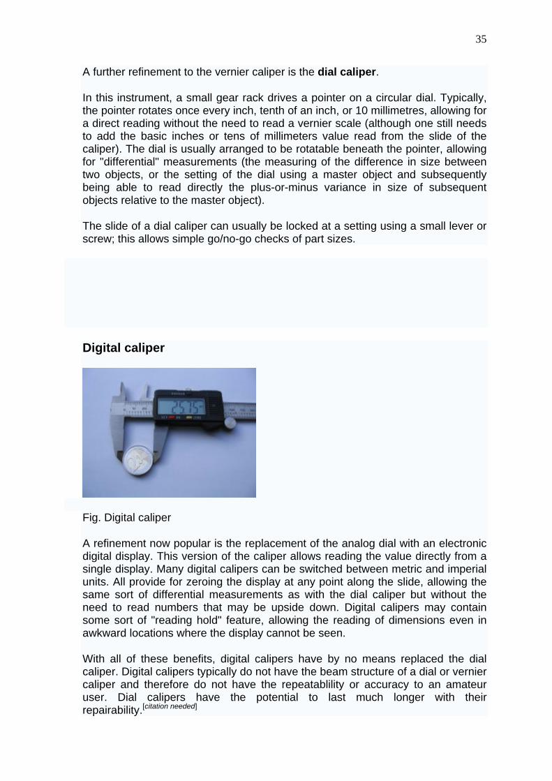
Fig. Digital caliper
A refinement now popular is the replacement of the analog dial with an electronic digital display. This version of the caliper allows reading the value directly from a single display. Many digital calipers can be switched between metric and imperial units. All provide for zeroing the display at any point along the slide, allowing the same sort of differential measurements as with the dial caliper but without the need to read numbers that may be upside down. Digital calipers may contain some sort of "reading hold" feature, allowing the reading of dimensions even in awkward locations where the display cannot be seen.
With all of these benefits, digital calipers have by no means replaced the dial caliper. Digital calipers typically do not have the beam structure of a dial or vernier caliper and therefore do not have the repeatablility or accuracy to an amateur user. Dial calipers have the potential to last much longer with their repairability.[citation needed]
36
Increasingly, digital calipers offer a serial data output to allow them to be interfaced with a personal computer. This means measurements can be taken and instantly stored in a spreadsheet or similar piece of software, significantly decreasing the time taken to take and record a series of measurements. The output of non-name brand calipers is usually 24 bit 90 kHz synchronous. A suitable interface to convert the output to RS232 levels and format can be built or purchased.
Like dial calipers, the slide of a digital caliper can usually be locked using a lever or thumb-screw.
Both dial and digital calipers can be used with accessories that extend their usefulness. Examples are a base that extends their usefulness as a depth gauge and a jaw attachment that allows measuring the center distance between holes.
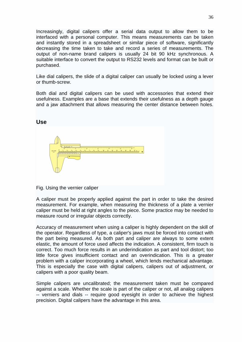
Use
Fig. Using the vernier caliper
A caliper must be properly applied against the part in order to take the desired measurement. For example, when measuring the thickness of a plate a vernier caliper must be held at right angles to the piece. Some practice may be needed to measure round or irregular objects correctly.
Accuracy of measurement when using a caliper is highly dependent on the skill of the operator. Regardless of type, a caliper's jaws must be forced into contact with the part being measured. As both part and caliper are always to some extent elastic, the amount of force used affects the indication. A consistent, firm touch is correct. Too much force results in an underindication as part and tool distort; too little force gives insufficient contact and an overindication. This is a greater problem with a caliper incorporating a wheel, which lends mechanical advantage. This is especially the case with digital calipers, calipers out of adjustment, or calipers with a poor quality beam.
Simple calipers are uncalibrated; the measurement taken must be compared against a scale. Whether the scale is part of the caliper or not, all analog calipers -- verniers and dials -- require good eyesight in order to achieve the highest precision. Digital calipers have the advantage in this area.
37
Calibrated calipers may be mishandled, leading to loss of zero. When a calipers' jaws are fully closed, it should of course indicate zero. If it does not, it must be recalibrated or repaired. It might seem that a vernier caliper cannot get out of calibration but a drop or knock can be enough. Digital calipers have zero set buttons.
Vernier scale
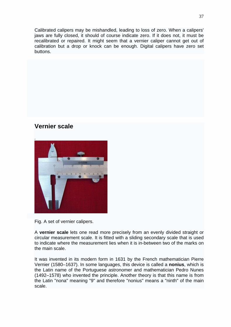
.
Fig. A set of vernier calipers.
A vernier scale lets one read more precisely from an evenly divided straight or circular measurement scale. It is fitted with a sliding secondary scale that is used to indicate where the measurement lies when it is in-between two of the marks on the main scale.
It was invented in its modern form in 1631 by the French mathematician Pierre Vernier (1580–1637). In some languages, this device is called a nonius, which is the Latin name of the Portuguese astronomer and mathematician Pedro Nunes (1492–1578) who invented the principle. Another theory is that this name is from the Latin "nona" meaning "9" and therefore "nonius" means a "ninth" of the main scale.
38
Verniers are common on sextants used in navigation, scientific instruments and machinists' measuring tools (all sorts, but especially calipers and micrometers) and on theodolites used in surveying.
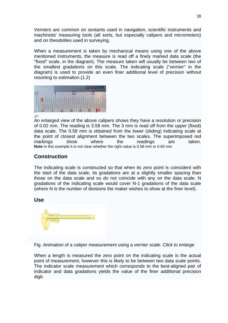
When a measurement is taken by mechanical means using one of the above mentioned instruments, the measure is read off a finely marked data scale (the "fixed" scale, in the diagram). The measure taken will usually be between two of the smallest gradations on this scale. The indicating scale ("vernier" in the diagram) is used to provide an even finer additional level of precision without resorting to estimation.(1.2)
An enlarged view of the above calipers shows they have a resolution or precision of 0.02 mm. The reading is 3.58 mm. The 3 mm is read off from the upper (fixed) data scale. The 0.58 mm is obtained from the lower (sliding) indicating scale at the point of closest alignment between the two scales. The superimposed red markings show where the readings are taken. Note In this example it is not clear whether the right value is 0.58 mm or 0.60 mm
Construction
The indicating scale is constructed so that when its zero point is coincident with the start of the data scale, its gradations are at a slightly smaller spacing than those on the data scale and so do not coincide with any on the data scale. N gradations of the indicating scale would cover N-1 gradations of the data scale (where N is the number of divisions the maker wishes to show at the finer level).
Use
Fig. Animation of a caliper measurement using a vernier scale. Click to enlarge
When a length is measured the zero point on the indicating scale is the actual point of measurement, however this is likely to be between two data scale points. The indicator scale measurement which corresponds to the best-aligned pair of indicator and data gradations yields the value of the finer additional precision digit.
39
Examples
On instruments using decimal measure, as shown in the diagram below, the indicating scale would have 10 gradations covering the same length as 9 on the data scale. Note that the vernier's 10th gradation is omitted.
On an instrument providing angular measure, the data scale could be in half-degrees with an indicator scale providing 30 1-minute gradations (spanning 29 of the half-degree gradations).
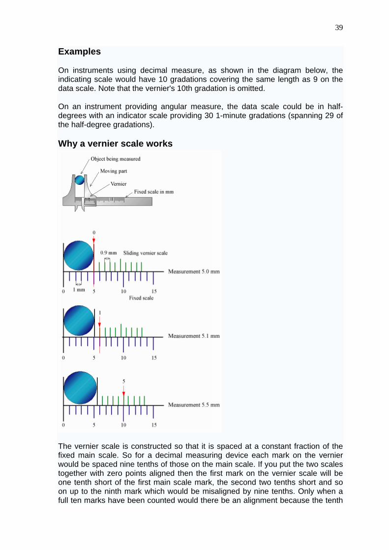
Why a vernier scale works
The vernier scale is constructed so that it is spaced at a constant fraction of the fixed main scale. So for a decimal measuring device each mark on the vernier would be spaced nine tenths of those on the main scale. If you put the two scales together with zero points aligned then the first mark on the vernier scale will be one tenth short of the first main scale mark, the second two tenths short and so on up to the ninth mark which would be misaligned by nine tenths. Only when a full ten marks have been counted would there be an alignment because the tenth
40
mark would be ten tenths, that is a whole main scale unit, short and will therefore align with the ninth mark on the main scale.
Now if you move the vernier by a small amount, say, one tenth of its fixed main scale, the only pair of marks which come into alignment will be the first pair since these were the only ones originally misaligned by one tenth. If we had moved it 2 tenths then the second pair and only the second would be in alignment since these are the only ones which were originally misaligned by that amount. If we had moved it 5 tenths then the fifth pair and only the fifth would be in alignment. And so on for any movement, only one pair of marks will be in alignment and that pair will show what is the value of the small displacement.
Micrometer (device)
A micrometer is a widely used device in mechanical engineering for precisely measuring thickness of blocks, outer and inner diameters of shafts and depths of slots. Appearing frequently in metrology, the study of measurement, micrometers have several advantages over other types of measuring instruments like the Vernier caliper.
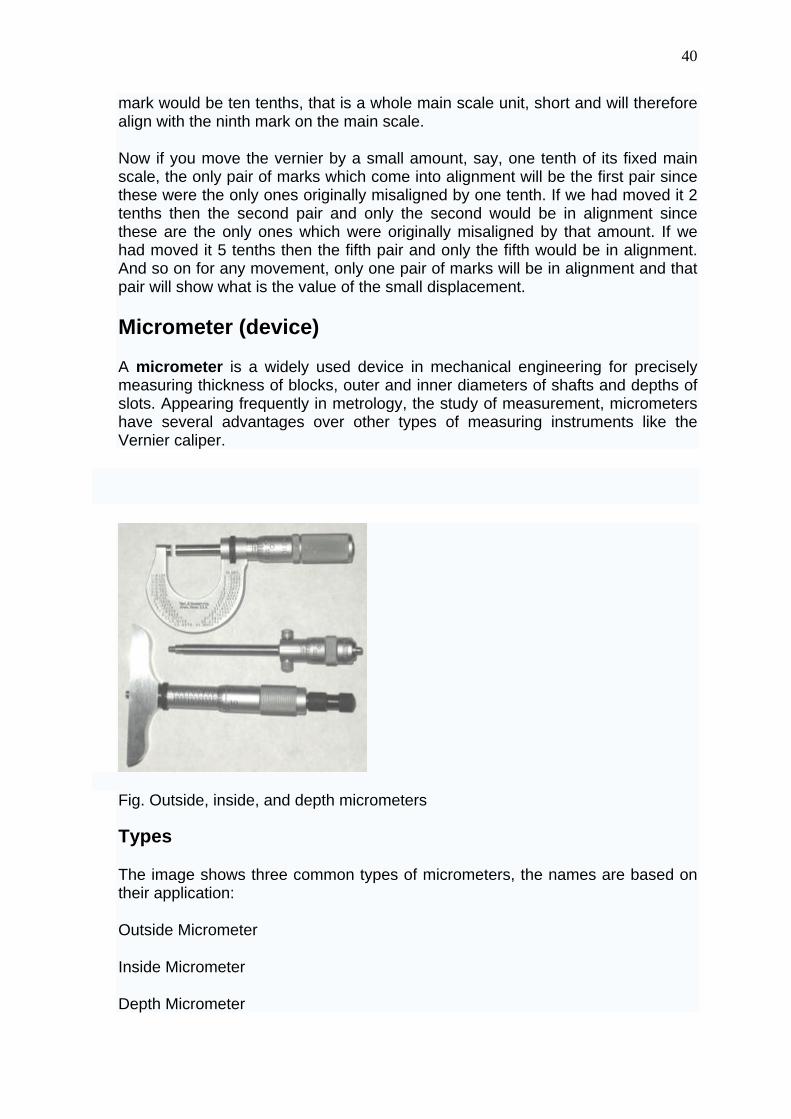
Fig. Outside, inside, and depth micrometers
Types
The image shows three common types of micrometers, the names are based on their application:
Outside Micrometer
Inside Micrometer
Depth Micrometer
41
Bore Micrometer
An outside micrometer is typically used to measure wires, spheres, shafts and blocks. An inside micrometer is commonly used to measure the diameter of holes, and a depth micrometer typically measures depths of slots and steps. The bore Micrometer is typically a three anvil head on a micrometer base used to accurately measure inside diameters.
The precision of a micrometer is achieved by a using a fine pitch screw mechanism.
An additional feature of micrometers is the inclusion of a spring-loaded ratchet thimble. Normally, one could use the mechanical advantage of the screw to force the micrometer to squeeze the material, giving an inaccurate measurement. However, by attaching a thimble that will ratchet or friction slip at a certain torque, the micrometer will not continue to advance once sufficient resistance is encountered.
Reading an inch-system micrometer
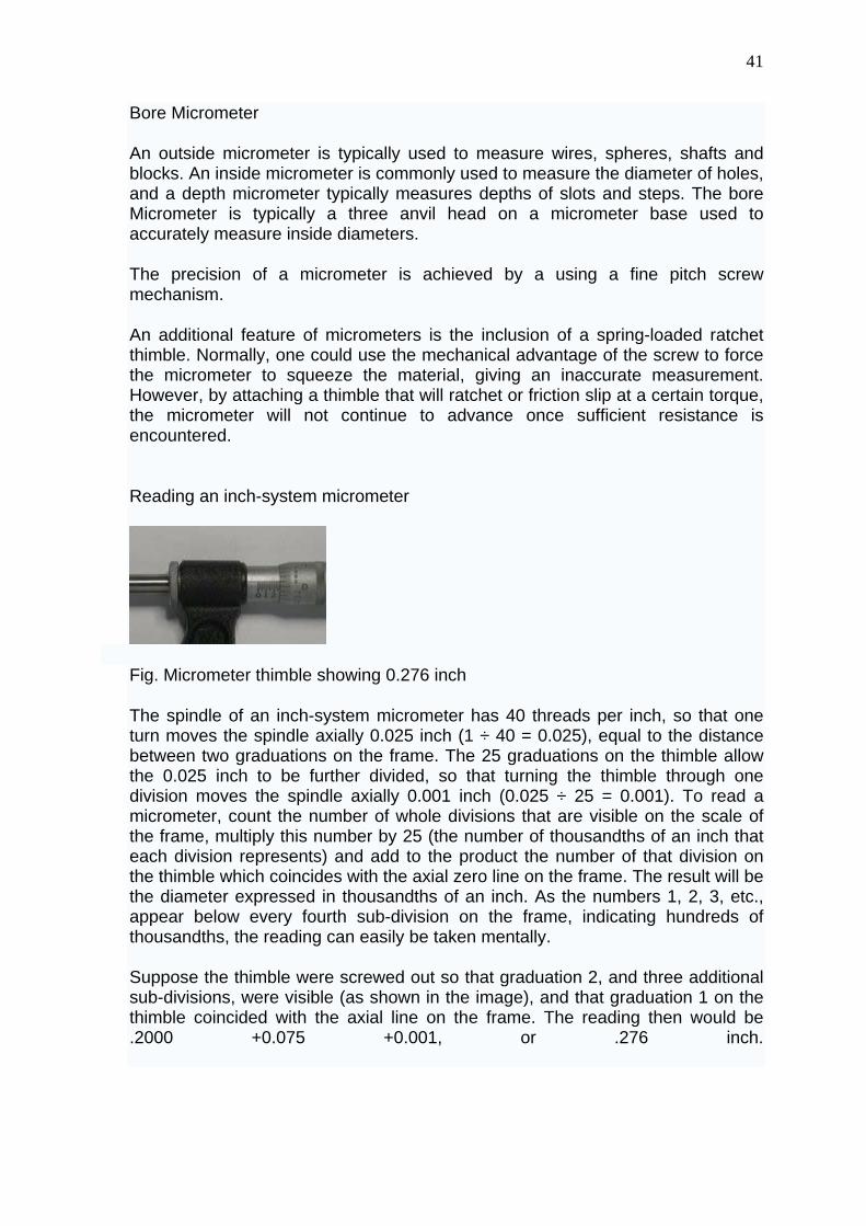
Fig. Micrometer thimble showing 0.276 inch
The spindle of an inch-system micrometer has 40 threads per inch, so that one turn moves the spindle axially 0.025 inch (1 ÷ 40 = 0.025), equal to the distance between two graduations on the frame. The 25 graduations on the thimble allow the 0.025 inch to be further divided, so that turning the thimble through one division moves the spindle axially 0.001 inch (0.025 ÷ 25 = 0.001). To read a micrometer, count the number of whole divisions that are visible on the scale of the frame, multiply this number by 25 (the number of thousandths of an inch that each division represents) and add to the product the number of that division on the thimble which coincides with the axial zero line on the frame. The result will be the diameter expressed in thousandths of an inch. As the numbers 1, 2, 3, etc., appear below every fourth sub-division on the frame, indicating hundreds of thousandths, the reading can easily be taken mentally.
Suppose the thimble were screwed out so that graduation 2, and three additional sub-divisions, were visible (as shown in the image), and that graduation 1 on the thimble coincided with the axial line on the frame. The reading then would be .2000 +0.075 +0.001, or .276 inch.
42
Reading a metric micrometer
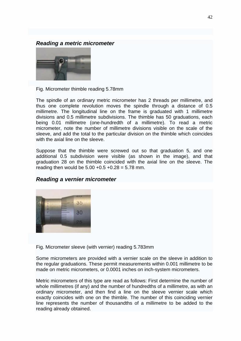
Fig. Micrometer thimble reading 5.78mm
The spindle of an ordinary metric micrometer has 2 threads per millimetre, and thus one complete revolution moves the spindle through a distance of 0.5 millimetre. The longitudinal line on the frame is graduated with 1 millimetre divisions and 0.5 millimetre subdivisions. The thimble has 50 graduations, each being 0.01 millimetre (one-hundredth of a millimetre). To read a metric micrometer, note the number of millimetre divisions visible on the scale of the sleeve, and add the total to the particular division on the thimble which coincides with the axial line on the sleeve.
Suppose that the thimble were screwed out so that graduation 5, and one additional 0.5 subdivision were visible (as shown in the image), and that graduation 28 on the thimble coincided with the axial line on the sleeve. The reading then would be 5.00 +0.5 +0.28 = 5.78 mm.
Reading a vernier micrometer
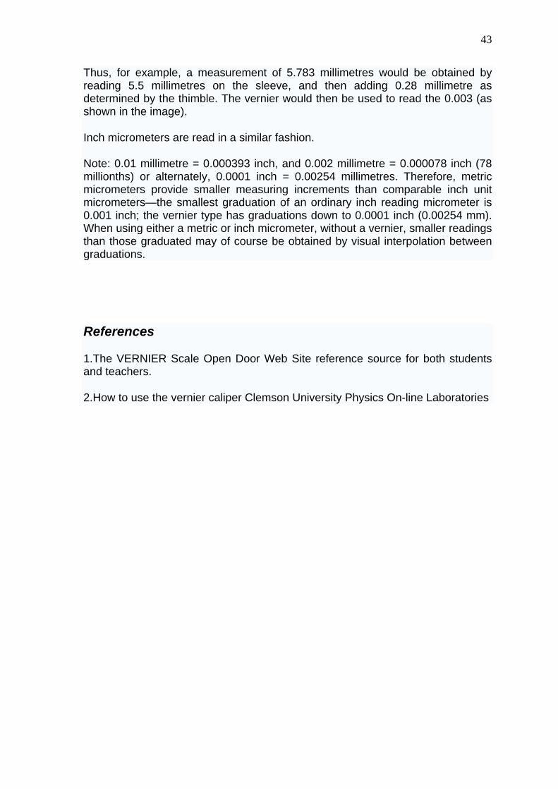
Fig. Micrometer sleeve (with vernier) reading 5.783mm
Some micrometers are provided with a vernier scale on the sleeve in addition to the regular graduations. These permit measurements within 0.001 millimetre to be made on metric micrometers, or 0.0001 inches on inch-system micrometers.
Metric micrometers of this type are read as follows: First determine the number of whole millimetres (if any) and the number of hundredths of a millimetre, as with an ordinary micrometer, and then find a line on the sleeve vernier scale which exactly coincides with one on the thimble. The number of this coinciding vernier line represents the number of thousandths of a millimetre to be added to the reading already obtained.
43
Thus, for example, a measurement of 5.783 millimetres would be obtained by reading 5.5 millimetres on the sleeve, and then adding 0.28 millimetre as determined by the thimble. The vernier would then be used to read the 0.003 (as shown in the image).
Inch micrometers are read in a similar fashion.
Note: 0.01 millimetre = 0.000393 inch, and 0.002 millimetre = 0.000078 inch (78 millionths) or alternately, 0.0001 inch = 0.00254 millimetres. Therefore, metric micrometers provide smaller measuring increments than comparable inch unit micrometers—the smallest graduation of an ordinary inch reading micrometer is 0.001 inch; the vernier type has graduations down to 0.0001 inch (0.00254 mm). When using either a metric or inch micrometer, without a vernier, smaller readings than those graduated may of course be obtained by visual interpolation between graduations.
References
1.The VERNIER Scale Open Door Web Site reference source for both students and teachers.
2.How to use the vernier caliper Clemson University Physics On-line Laboratories