Embed Size (px)
Citation preview
केवऱ कायााऱयीन उपयोग हेत ु
(For Official Use Only)
भारत सरकार GOVERNMENT OF INDIA
रेऱ मंत्राऱय MINISTRY OF RAILWAYS
0
Hand Book
on
Maintenance Instructions for New
Technological Developments in LHB
Coaches
Volume 1 - Maintenance Management
IRCAMTECH/GWL/MECH/2021-22/LHB/HB/1.0
JULY, 2021

LHB Technological Development Maintenance Management
IRCAMTECH/GWL/MECH/2021-22/LHB/HB/1.0
2 of 30
THIS PAGE IS INTENTIONALLY LEFT BLANK

LHB Technological Development Maintenance Management
IRCAMTECH/GWL/MECH/2021-22/LHB/HB/1.0
3 of 30
Contents Foreword .................................................................................................................................... 5
Preface ........................................................................................................................................ 7
Quality Policy .............................................................................................................................. 8
Our Objective .............................................................................................................................. 9
Amendment and Revisions ................................................................................................................ 10
1. Structure of Maintenance Manual .................................................................................... 11
1.1 Volume -1 : Maintenance Management ............................................................................... 11
1.2 Volume -2: System Documentation ...................................................................................... 11
1.3 Volume -3 : Original Equipment Manufacturer Documentation. ......................................... 12
2 Documentation Management ........................................................................................... 12
2.1 Basic ....................................................................................................................................... 12
What is PDF?.................................................................................................................................. 12
2.2 System Requirement for Adobe Reader DC software ........................................................... 12
Windows ........................................................................................................................................ 12
Macintosh ...................................................................................................................................... 12
2.3 Installing Software ................................................................................................................. 13
2.4 Mobile Platforms ................................................................................................................... 13
3 Maintenance & Reliability ................................................................................................. 13
3.1 Planned Maintenance ........................................................................................................... 13
Safety checks ................................................................................................................................ 14
Trip Inspections ........................................................................................................................... 14
Preventive Maintenance (Daily/Monthly/Quarterly etc.) ........................................................ 14
3.2 Unplanned Maintenance ....................................................................................................... 15
3.3 Recording the Maintenance .................................................................................................. 15
3.4 Reliability ............................................................................................................................... 15
3.5 Failure Investigation .............................................................................................................. 16
3.6 Quality Management............................................................................................................. 17
3.7 Warranty Liability .................................................................................................................. 18
4 Safety, Health and Environment ....................................................................................... 18
4.1 Workplace Safety .................................................................................................................. 19
4.2 Working with Tools................................................................................................................ 20
4.3 Fire Safety .............................................................................................................................. 22
4.4 Controlling Electrical Hazards ................................................................................................ 25
4.5 Health Hazards ...................................................................................................................... 27
4.6 Personal Protective Equipments ........................................................................................... 27

LHB Technological Development Maintenance Management
IRCAMTECH/GWL/MECH/2021-22/LHB/HB/1.0
4 of 30
4.7 Precautions for Diesel Engines .............................................................................................. 28
4.8 Environment .......................................................................................................................... 29
4.9 Energy Management ............................................................................................................. 29

LHB Technological Development Maintenance Management
IRCAMTECH/GWL/MECH/2021-22/LHB/HB/1.0
5 of 30
Foreword
The LHB coaches were first introduced in December 2003 and are widely used in Indian Railways network. Since its first use, this design was widely adopted due to its lightweight construction and high safety & comfort standards.
To meet passenger expectation and for making the journey more comfortable , Indian Railways has introduced numerous technical innovations and intelligent solutions for various passenger amenities. Vacuum assisted flushing system in toilet, fire detection and suppression system, automatic doors, sealed gangways, passenger information and address system are few mentionable features introduced recently.
These introduced amenities and features uses latest technology, which will require specific maintenance instructions from their manufacturer or supplier. Field unit were facing the problem as these were not easily available.
IRCAMTECH Gwalior has prepared the Maintenance Handbook in association with concerned teams of RDSO, Production Units (ICF, MCF & RCF) and respective OEMs. All maintenance instructions have been presented revised format for better understanding and to usefully carry out prescribed maintenance schedules.
A very special thanks and acknowledgement to RDSO, Production Units and OEMS, for finalizing this documentation in a short time span despite the travel limitations due to second wave of nCOVID-19 pandemic.
As the concept and technology used is new, changes to some of the schedule activities based on the field experience may be required. Field units are therefore, requested to keep a note for further changes and modifications in maintenance schedules and send details to IRCAMTECH.
Please feel free to write us for any suggestion for further improvements.
RDSO, Lucknow Jitendra Singh Date: 31/07/2021 Principal Executive Director

LHB Technological Development Maintenance Management
IRCAMTECH/GWL/MECH/2021-22/LHB/HB/1.0
6 of 30
THIS PAGE IS INTENTIONALLY LEFT BLANK

LHB Technological Development Maintenance Management
IRCAMTECH/GWL/MECH/2021-22/LHB/HB/1.0
7 of 30
Preface
Linke Hofmann Busch (LHB) coaches are widely used in Indian Railways network. Higher comfort & safety levels, higher passenger carrying capacity and low maintenance are few of its features amongst the list of many.
Indian Railways has introduced new amenities and safety features in the recently rolled out LHB coaches from its production units. With the aim of improving the comfort and safety in LHB coaches, these features use the latest technology available in the railroad industry.
IRCAMTECH has prepared Maintenance Handbook on New Technological Developments in LHB Coaches with inputs from RDSO, Production Units (ICF, MCF & RCF) and respective OEMs to help in maintaining these newly introduced systems. We gratefully acknowledge the above mentioned agencies in finalizing this documentation.
Technological up-gradation, systems improvement and learning are a continuous process. Please feel free to write us for any addition/ modification in this document
CAMTECH, Gwalior Manoj Kumar Date: 31/07/2021 Director /Mechanical

LHB Technological Development Maintenance Management
IRCAMTECH/GWL/MECH/2021-22/LHB/HB/1.0
8 of 30
Quality Policy
“We at IRCAMTECH Gwalior are committed to maintain and update transparent standards of services to develop safe, modern and cost effective railway technology complying with statutory and regulatory requirements, through excellence in research, designs and standards by setting quality objectives, commitment to satisfy applicable requirements and continual improvements of the quality management system to cater to growing needs, demand and expectations of passenger and freight traffic on the railways through periodic review of quality management systems to achieve continual improvement and customer appreciation. It is communicated and applied within the organization and making it available to all the relevant interested parties”.

LHB Technological Development Maintenance Management
IRCAMTECH/GWL/MECH/2021-22/LHB/HB/1.0
9 of 30
Our Objective To upgrade maintenance technologies and methodologies and achieve improvement in productivity and performance of all Railway assets and manpower which inter-alia would cover reliability, availability, utilization and efficiency.
CAMTECH is continuing its efforts in the documentation and up gradation of information on maintenance practices of railway assets. Over the years a large number of publications on railway assets have been prepared in the form of handbooks, pockets books, pamphlets & video films etc. These publications have been uploaded on the internet as well as on rail net. For downloading these publications please do following:
1. On internet visit : www.rdso.indianrailways.gov.in Go to Directorates
CAMTECH Publications for downloadMechanical Engineering
2. On Railnet visit RDSO website at 10.100.2.19 Go to Directorates CAMTECH
Publications for download Mechanical Engineering
For any further information regarding publications please contact:
Director /Mechanical
Landline - 0751 - 2470890
CUG - 9752447040
E-mail - [email protected]
Fax- 0751- 2470841
Write us at:
Director (Mechanical)
Indian Railways Centre for Advanced Maintenance technology
In front of Hotel Adityaz, Airport Road
Maharajpur, Gwalior (M.P), Pin code –474 005

LHB Technological Development Maintenance Management
IRCAMTECH/GWL/MECH/2021-22/LHB/HB/1.0
10 of 30
All rights reserved. This book or any portion thereof may not be reproduced or used in any manner whatsoever without authorization from Indian Railways.
All technical information and guidelines are latest at the time of publishing and are subjected to change due to technology updates and requirements.
Amendment and Revisions The correction slips to be issued in future for this report will be numbered as follows:
IRCAMTECH/GWL/MECH/2021-22/LHB/HB/1.0# XX date .......
Where “XX” is the serial number of the concerned correction slip (starting from 01 onwards).
Version Date Corrections Remarks
1.00 31/07/2021 First Release --

LHB Technological Development Maintenance Management
IRCAMTECH/GWL/MECH/2021-22/LHB/HB/1.0
11 of 30
Volume -1: Maintenance Management
Volume -2 : System Documentation
Volume -3 : Original Equipment Manufacturer Documentation
The topics covered in this volume are for introductory purpose and contain only brief description. In general all maintenance units to follow the general legal and other binding regulations related to quality, Occupational safety and health, environment, energy conservation etc.
1. Structure of Documentation This Maintenance Manual provides maintenance instruction with procedures and guidelines for maintaining different systems and components. It focuses on various systems, components, procedures and other related information to carry out maintenance activities. This manual should be used as base document to frame maintenance guidelines for the maintenance activities for design developments in LHB design coaches.
For ease of readability and to explain the complex maintenance related information to the end user effectively, the documentation has been divided into three volumes:
1.1 Volume -1 : Maintenance Management Volume -1 is the introductory part of Maintenance documentation; here the concept of Maintenance and Maintenance Management has been explained. How emphasis on reliability will reduce the avoidable failures and ultimately increase operational efficiency and affect maintenance budget has been briefly explained. Occupational health with emphasis on safety and environment factor has been included in this volume.
This volume also contains brief information about the structure of documentation and chapters in other volumes. It is expected from end users to go through Volume - 1 before referring to Volume - 2 and Volume - 3.
1.2 Volume -2: System Documentation This volume contains the technical details related to various systems, components and structure in VEHICLE. This part of documentation also includes the details of other related topics such as scheduling, tools, troubleshooting etc. Its contents are:
Technical Details
Cleaning
Schedule of Examination
Tools and Accessories
Maintenance
Drawing Index
General Information
Trouble Shooting

LHB Technological Development Maintenance Management
IRCAMTECH/GWL/MECH/2021-22/LHB/HB/1.0
12 of 30
All technical information & manual provided by OEM's are latest at the time of publishing and are subjected to change due to technology updates and requirements.
LHB document e-file is available at IR-CAMTECH website publication page for download. Before referring the manual please ensure you have the latest issue available.
1.3 Volume -3 : Original Equipment Manufacturer Documentation. This volume of the maintenance manual contains maintenance/ operational/ installation related document from various OEM associated with different system and components of vehicle.
2 Documentation Management
2.1 Basic The LHB document is available in hard copy as well as in electronic format. To allow printing and reading the manual on electronic devices across different platforms, all files of the documentation have been stored in PDF format.
What is PDF? Portable Document Format (PDF) is a file format used to present and exchange documents reliably, independent of software, hardware, or operating system. PDF is now an open standard maintained by the International Organization for Standardization (ISO). PDFs can contain links and buttons, form fields, audio, video, and business logic. They can also be signed electronically and are easily viewed using free Acrobat Reader DC software.
2.2 System Requirement for Adobe Reader DC software
Windows
1.5GHz or faster processor
Windows Server 2008 R2 (64 bit), 2012 (64 bit), 2012 R2 (64 bit), 2016 (64 bit), or2019 (64 bit); Windows 7 SP1 (32 bit and 64 bit), Windows 8, 8.1 (32 bit and 64 bit),or Windows 10 (32 bit and 64 bit)
1GB of RAM
450MB of available hard-disk space
1024x768 screen resolution
Internet Explorer11
Macintosh
Intel processor
macOS v10.12, macOS v10.13, macOS v10.14, or macOSv10.15
1GB of RAM
380MB of available hard-disk space
LHB Technological Development Maintenance Management
IRCAMTECH/GWL/MECH/2021-22/LHB/HB/1.0
13 of 30
1024x768 screen resolution
Safari 10.0, or 11.0 (browser plug-in for Safari supported on 64-bit Intel
processor only)
2.3 Installing Software Follow these steps to install Acrobat Reader DC using Internet Explorer.
Close all versions of Reader. Close any browser that is displaying a PDF.
Go to the Adobe Acrobat Reader download page and click Install now.
When the file download message appears at the bottom of the browser
window, click Run.
When you see the confirmation message that the installation is
complete, click Finish.
2.4 Mobile Platforms PDF files can be viewed on smart phones and portable devices. Following are the commonly used portable devices platforms where PDF files can be read.
Android
iOS
Windows Phone.Some of the portable devices and mobile phones have in - built PDF reader with their operating system, so you will be not required to install reader software to view PDF files.
3 Maintenance & Reliability Maintenance involves functional checks, servicing, repairing or replacing of necessary devices, equipment, machinery, and supporting utilities. Maintenance here can be broadly defined into two categories
Planned Maintenance where activities can be planned as per requirement so that failures can be avoided and components and equipment achieve their service lifespan.
Unplanned maintenance which cannot be planned but all the activities has to be completed.
The modern concept to deal with the maintenance activities is planning the schedule for maintenance of components and sub-assemblies and other utilities, which forms the balanced between maintenance activities which can be planned to those which cannot be planned but are necessary. Thus the components can be used in a cost-saving way up to the limits of their expected service life.
3.1 Planned Maintenance Planned maintenance is a type of maintenance that is done at a regular interval while the equipment is still functioning with the objective of preventing failure or reducing the likelihood of failure. Planned maintenance can be time based i.e. every week, every month etc. Or usage based for example every 150 cycles, every 10,000hrs etc. Or distance travelled based for example every 10,000km.

LHB Technological Development Maintenance Management
IRCAMTECH/GWL/MECH/2021-22/LHB/HB/1.0
14 of 30
All faults reported by the operating crew / Loco Inspectors or recorded by the vehicle’s recorder must be attended by the maintenance staff. A decision should be made here between faults which affect the operation or represent a reduction in the operating characteristics and must thus be eliminated immediately or those which can be eliminated more conveniently during the next maintenance schedule of the vehicle concerned and which are can planned accordingly. Comprehensive system knowledge both in the electrical/electronic/mechanical sector and operating is required to eliminate failures.
Planned maintenance objectives are
To avoid premature failures.
To reduce functional failures
To ensure the availability as per requirement.
Planned maintenance activities include safety checks, trip inspections, preventive maintenance, overhaul and custom modifications.
Safety checks Safety checks shall be carried out in order to detect damage to components, if any which resulted from external influences during operation which might be the consequence of various factors. From the technical point of view, safety checks are not required in any case, however, are recommended as preventive measures. Visible damage to sub-assemblies and components will thus be recognized early which might under certain circumstances result in serious consequential damage to the equipment and life. The relevant precautions thus limit unplanned failures and casualties and thus reduce overall cost. Safety Inspection is carried out by the driver prior to the beginning of travel or by the maintenance staff during the incoming or at release of vehicle after completion of the maintenance schedule.
Trip Inspections The trip inspections as part of the planned maintenance work are carried out primarily to assess the condition of coaches and its components. Primarily, the trip inspection is related to functioning, safety and maintenance. The results of the incoming/outgoing inspections in trip schedule are documented and evaluated as requirement. Corrections are made immediately, if necessary. Comprehensive measures are planned and carried out as soon as possible.
Preventive Maintenance (Trip/Monthly/Six Monthly etc.) Preventive maintenance includes: the checking of functions, measuring and comparing with specified reference values, adjustment and optimization, proper cleaning and lubricating the mechanical units and replaced of schedule components and assemblies. Repair work and replacement of wearing parts is carried out during the maintenance activities.
Planned repair work is done primarily according to the results of incoming/outgoing inspections or analysis. Parts will be subject to preventive repair are replaced if functional troubles are expected prior to the next maintenance interval.
Custom Modifications Custom modification in various system/assemblies and components may be required to meet operational requirements, to reduce failures or to improve the efficiency. As per
LHB Technological Development Maintenance Management
IRCAMTECH/GWL/MECH/2021-22/LHB/HB/1.0
15 of 30
requirement custom modification can be deferred or can be completed on priority basis.
Overhaul
Overhauling is required depending on various factors to get the desired performance. Factors which decide the overhauling period are
Age.
Hours of operation.
Specification by manufacturer.
3.2 Unplanned Maintenance As discussed in planned maintenance visible defects due to wear are eliminated by replacing or renewing components. Even if these preventive measures are carried out with utmost care it is not possible to prevent all failures of components due to wear, ageing or loading or other external factors. The functional and operating failures which occur due to these influences require work and repairs which are called unplanned maintenance repair works. This type of maintenance of requires repairs to be attended immediately but in some cases it can be deferred as per operational requirements.
3.3 Recording the Maintenance Recording the maintenance and servicing work carried out is vital. This helps in:
Processing of guarantee claims and keeping record of that.
Conclusions can be drawn about the provision of spare and wearing parts.
Analysis of failure trend in particular component or a system.
Performance evaluation of components.
For the future research and development.
The following data must be recorded during the maintenance and servicing measure:
Date of Incoming, Outgoing and activities
Time
Maintenance or repair details carried out by: Maintenance personnel , approving authority
Serial number/Component number
Hours of operation/kilometer coverage
Measures initiated: Description of activity and fault elimination
In case of fault: Type of damage/place of installation/cause of damage( if known)
In case of failure: Complete detail of failure including the statement of operating crew.
Material used: Material description, Identification number (PIL) of the new component installed
Time expenditure
Dead time (if necessary)Or any other information necessary for efficient maintenance may be included.
3.4 Reliability Reliability is ability to consistently perform its intended function without degradation or failure. The maintenance strategy is designed keeping in mind the reliability factor, otherwise the principal risk factors arise due to failure are:

LHB Technological Development Maintenance Management
IRCAMTECH/GWL/MECH/2021-22/LHB/HB/1.0
16 of 30
Safety
Operational Effectiveness
Maintenance budgetSuccessfully implementing maintenance strategy which is based on reliability improvement will lead to increase in cost effectiveness, reduced maintenance, and a greater understanding of the level of risk that maintenance unit is managing due to sudden failure of equipment or component. The reliability based maintenance for effective functioning should address the below mentioned seven questions.
1 What is the part/component supposed to do and its associated performance
standards?
2 In what ways can it fail to provide the required functions?
3 What are the events that cause each failure?
4 What happens when each failure occurs?
5 In what way does each failure matter?
6
What systematic task can be performed proactively to prevent, or to diminish to a
satisfactory degree, the consequences of the failure?
7 What must be done if a suitable preventive task cannot be found?
3.5 Failure Investigation As discussed in topic - 3.4 principal risk factors which arise due to failure are safety, operational effectiveness and maintenance budget. Safety is the most important factor among them, failures of critical item and component in rolling stock may possess danger of severe consequences such as derailment. On the second part failure of component or part may result in failure of system as a consequence which results in delay or blockage which affects operational effectiveness. Finally every maintenance schedule is designed to cater the technical and operational need to run the VEHICLE for specified time duration, due to failure maintenance needs to be done before schedule which affects the maintenance budget.
Failure investigation is the process of analyzing the component data or the component itself

LHB Technological Development Maintenance Management
IRCAMTECH/GWL/MECH/2021-22/LHB/HB/1.0
17 of 30
to determine the reasons for degraded performance or catastrophic failure of a component and to take corrective actions or fix liability. To determine the root cause of a failure, advanced analysis techniques may be employed not just to verify compliance of the part to defined assembly but to determine the origin of the observed failure mechanism. It is important to know as much detailed information as possible. They may include
Technical Specification of the component.
Storage condition before fitment.
Handling before fitment.
Compliance to guidelines during its fitment.
Condition and calibration of tools and equipments used.
Failure history of components from same manufacturer.
Failure history of similar components from different manufacturer.
Performance on different maintenance units.
Its location and working in the system.
Environmental conditions.
External factors such as non standard or contaminated lubricants, coolants etc.
Actual operating conditions.
Failure mode or degraded performance.
Metallurgical investigation or other Non Destructive Testing reports if necessary.
Statement from working crew or maintenance staff from the site of failure.
Implementing the outcome from failure investigation
At the component manufacturer. Identifying problems with raw materials, handling, manufacturing processes, testing, etc., that can be improved, increasing the production yield and the product quality.
At maintenance unit/sheds level. Knowing the problem origin, and being able to provide solutions to prevent recurrence-applying the correct risk management techniques for each application / need. Sometimes the problem is directly related to the component, and depending on the failure mechanism, corrective actions can be implemented as follows:
To change the supplier.
To replace the type by a more adequate one.
To replace the lot.
To suggest any design modification.
To introduce any additional checks during assembly. To check failures by introducing drives for implementing changes.
3.6 Quality Management The maintenance activities are done by humans, which means mistakes will be made regardless of how rigorous the procedures are and how well they are trained. The errors by maintenance crew can have severe consequences, starting from small functional failures to catastrophes like derailment. So quality management in maintenance unit is essential so that the intended function of maintenance activity is satisfied and component can complete its designed lifespan. Quality management also ensures that quality processes are embedded to maintenance practices so that proactive measures are taken to ensure that no failures occur rather than
LHB Technological Development Maintenance Management
IRCAMTECH/GWL/MECH/2021-22/LHB/HB/1.0
18 of 30
reactive measures which are taken after failures. Essentially, it involves: Establishing zero-defect conditions during maintenance activity by including
quality practices. Preventing defects after maintenance activity by strictly keeping the test
parameters within a standard range of values, and controlling operating parameters within standards.
Predicting the possibility of defects by monitoring trends in the measured values, and taking preventive action.
In case of failure, pinpointing the origin of failure and controlling the root cause so that its reoccurrence can be eliminated.
Discouraging all the activities which do not comply with quality process and make them quality complaint.
3.7 Warranty Liability
Most parts or components in LHB coaches come under warranty for time period specified. It is provided by manufacturing unit of the railways or by original equipment manufacturer. But warranty are bound to terms and situations in which repairs or exchanges will be made in the event that the part or component does not function as originally described or intended.
Some common points to observe causing warranty to void are:
Damage due to improper use, storage or handling of parts/components.
Unauthorized alterations in mechanical/electrical system, engine, under
truck or structure.
Spare used in the assembly which does not meet the specification.
Expired component used in assembly such as rubber components.
Maintenance/repair/assembly carried out by untrained person.
Improper operating conditions such as overloading, inappropriate
sequence of operations etc.
Improper repair and maintenance techniques such as electronic cards not
removed during welding repair in the vehicle.
4 Safety, Health and Environment
Occupational Safety and Health
It is important to have all aspects of health and safety and to have strong focus on primary prevention of hazards that may sometimes cause grievous injuries to the maintenance staff. It is necessary to have factors affecting health and safety of maintenance staff evaluated from time to time. The terminology used related to safety and health in general terms are Risk - It is a combination of the probability that a particular outcome will occur. Hazard - A hazard is something that can cause harm if not controlled. Outcome - The outcome is the harm that results from an uncontrolled hazard.
Hazard identification
Hazard identification or assessment is an important step in the overall risk assessment and risk management process. It is where individual work hazards are identified, assessed and controlled/eliminated as close to source (location of the hazard) as reasonably as possible. A hazard-based program should be developed that may not be able to eliminate all risks, but

LHB Technological Development Maintenance Management
IRCAMTECH/GWL/MECH/2021-22/LHB/HB/1.0
19 of 30
also it should not accept satisfactory /risky outcomes.
Risk Assessment
The assessment should include practical recommendations to control the risk. Generally speaking, control measure should lower risk at an acceptable level. It should be kept in mind that risk management requires risk to be managed to a level which is as low as is reasonably practical. Its main function is
Identify the hazards.
Identify all person affected by the hazard and how they are affected.
Evaluate the risk.
Identify and prioritize suitable & feasible control measures
Below are some common hazards related to safety and health commonly observed during day to day maintenance activities are:
Hearing loss due to hazardous noise levels especially observed on people working for prolonged hours on engine testing, machining process and pneumatic horns.
Injuries and fatalities due to fall from height.
Injuries due to machines as they have moving parts, sharp edges, hot surfaces.
Injuries, burns and impaired vision due to welding.
Skin allergies due to contact of various petroleum based products and chemicals.
Respiratory diseases due to inhalation of smoke, dust and fumes.
Psychosocial problems which include risks to the mental and emotional well-being of workers, such as feelings of job insecurity, long work hours, and poor work-life balance.
4.1 Workplace Safety
To ensure a safe work environment, where assurance of occupational health and safety
is the norm rather than an afterthought, a positive, strong safe work place environment
is needed. Few points mentioned below broadly covers the factors and will help in
improving workplace safety.
Safety posters needed to be displayed throughout the maintenance units
Properly stocked and maintained first aid kit should be available.
All work areas are free from obstructions.
All work areas should be properly illuminated.
All work area should have proper ventilation.
Fire extinguishers marked and maintained should be available at work area.
Fork lift and overhead cranes to be operated by authorized person under supervision.
Do not stay or work below suspended loads.
All tools and equipments responsible for lifting loads, applying torque should be

LHB Technological Development Maintenance Management
IRCAMTECH/GWL/MECH/2021-22/LHB/HB/1.0
20 of 30
regularly tested for cracks and defects.
When replacing individual parts and large sub-assemblies attach and secure the latter at the lifting tackle to avoid danger. Use suitable and technically proper lifting tackle only with a sufficient load-bearing capacity.
Welding/brazing and cutting work in the maintenance area should be done under proper supervision.
Prior to do welding, cutting, and grinding work, clean the repair area and its surroundings from combustible matter and ensure sufficient ventilation for danger of explosion.
Stairs and walkways should be properly marked.
Guard rails should be present in elevated areas.
Anti slip surfaces should be ensured on stairs and slides.
All tools and equipments have rotating/moving parts should have safety guards.
Emergency mock drills to be carried out on timely to familiarize the maintenance staff in case of emergency
Common gathering areas (in case of emergency) should be properly marked.
All machinery and plant to be maintained and inspected regularly.
Only authorized person to use specialized tools.
All maintenance staff to wear personal protective equipments (PPE) at all times during working in the maintenance area.
Safety audit to be carried out at regular intervals.
4.2 Working with Tools
Hand tools
All tools are manufactured with safety standards but accident often occurs before steps are taken to search out and avoid or eliminate tool-related hazards. In the process of removing or avoiding the hazards, workers must learn to recognize the hazards associated with the different types of tools and the safety precautions necessary to prevent those hazards.
Impact tools such as chisels or wedges are unsafe if they have blunt heads. The heads might shatter on impact.
Around flammable substances, sparks produced by iron and steel hand tools can be a dangerous ignition source.
Tools such as spanner , pipe wrenched sockets etc. should not have worn out surfaces , it might slip during working and might cause injury
Tools if not properly calibrated can cause the component / part to fail prematurely.
Each tool should be tested regularly to check for cracks and other defects.
Safety requires that floors and work surface to be kept as clean and dry as possible to prevent accidental slips with or around dangerous hand tools.
Every tool has its defined working function and capability, except that that it should not be used for any other purpose. For example screw driver should not be used as chisel, spanner, torque wrenches should not used as lever to shift load.

LHB Technological Development Maintenance Management
IRCAMTECH/GWL/MECH/2021-22/LHB/HB/1.0
21 of 30
Power tools
Power tools can be hazardous when improperly used. There are several types of power tools, based on the power source they use: electric, pneumatic, liquid fuel, hydraulic and powder-actuated. The following general precautions should be observed by power tool users:
Never carry a tool by the cord. Never pull the cord to disconnect it from the switchboard. Keep cords away from heat, oil and sharp edges. Disconnect tools when not in use, before servicing, and when changing accessories
such as blades, bits and cutters. All observers should be kept at a safe distance away from the work area. Secure work with clamps or a vise, freeing both hands to operate the tool. Avoid accidental starting. The worker should not hold a finger on the switch
button while carrying a plugged-in tool. Tools should be maintained with care. They should be kept sharp and clean for the
best performance. Follow instructions in the user's manual for lubricating and changing accessories.
Be sure to keep good footing and maintain good balance. The proper apparel should be worn. Loose clothing, ties or jewelry can become
caught in moving parts. All tools that are damaged shall be removed from use and tagged.
Guards
Hazardous moving parts of a power tool need to be safeguarded. For example, belts, gears,
shafts, pulleys, sprockets, spindles, drums, fly wheels, chains, or other reciprocating, rotating
or moving parts of equipment must be guarded if such parts are exposed to contact by
maintenance staff.
Safety Switches
The following hand-held powered tools are equipped with a momentary contact on-off
control switch: drills, tappers, fastener drivers, horizontal, vertical and angle grinders, other
similar tools. These tools also may be equipped with a lock-on control provided that turnoff
can be accomplished by a single motion of the same finger or fingers that turn it on.
Electric Tools
Among the chief hazards of electric-powered tools are burns and slight shocks which can
lead to injuries. Under certain conditions amount of current can result in grievous injury. A
shock also can cause the user to fall off a ladder or other elevated work surface. These
general practices should be followed when using electric tools:
Electric tools should be operated within their design limitations. Gloves and safety footwear are recommended during use of electric tools. When not in use, tools should be stored in a dry place. Electric tools should not be used in damp or wet locations. Work areas should be well lighted.
Powered Abrasive Wheel Tools
Powered abrasive grinding, cutting, polishing, and wire buffing wheels create special safety

LHB Technological Development Maintenance Management
IRCAMTECH/GWL/MECH/2021-22/LHB/HB/1.0
22 of 30
problems because they may throw off flying fragments. Before an abrasive wheel is
mounted, it should be inspected closely and sound- or ring-tested to be sure that it is free
from cracks or defects. To test, wheels should be tapped gently with a light non-metallic
instrument. If they sound cracked or dead, they could fly apart in operation and so must not
be used. A sound and undamaged wheel will give a clear metallic tone or "ring."
To prevent the wheel from cracking, the user should be sure it fits freely on the spindle. The
spindle nut must be tightened enough to hold the wheel in place, without distorting the
flange. Follow the manufacturer's recommendations. Care must be taken to assure that the
spindle wheel will not exceed the abrasive wheel specifications.
Due to the possibility of a wheel disintegrating (exploding) during start-up, the employee
should never stand directly in front of the wheel as it accelerates to full operating speed.
Portable grinding tools need to be equipped with safety guards to protect workers not only
from the moving wheel surface, but also from flying fragments in case of breakage.
Pneumatic Tools
Pneumatic tools are powered by compressed air and include drills, hammers etc. Eye
protection is required and face protection is recommended for employees working with
pneumatic tools. Noise is another hazard. Working with noisy tools such as jackhammers
requires proper, effective use of hearing protection. When using pneumatic tools,
maintenance staff must check to see that they are fastened securely to the hose to prevent
them from becoming disconnected.
Hydraulic Power Tools
Fluid used in hydraulic power tools must be as per specification and must retain its operating
characteristics at the most extreme temperatures to which it will be exposed. Always check
for overheating and allow cooling for specified time before continuous use.
The manufacturer's recommended safe operating pressure for hoses, valves, pipes, filters
and other fittings must not be exceeded. Personal protective equipments must be used at all
times as burst pressure lines can cause eye or skin injury.
Jacks
Jack whether lever and ratchet jacks, screw jacks and hydraulic jacks, make certain of the
following points:
Base rests on a firm level surface, Jack is correctly centered, Jack head bears against a level surface, and
Lift force is applied evenly.
Proper maintenance of jacks is essential for safety. All jacks must be inspected before each use and lubricated regularly. If a jack is subjected to an abnormal load or shock, it should be thoroughly examined to make sure it has not been damaged.
4.3 Fire Safety
Fire is a chemical reaction that requires three elements to be present for the reaction to take
LHB Technological Development Maintenance Management
IRCAMTECH/GWL/MECH/2021-22/LHB/HB/1.0
23 of 30
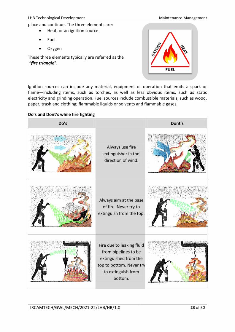
place and continue. The three elements are:
Heat, or an ignition source
Fuel
Oxygen
These three elements typically are referred as the “fire triangle".
Ignition sources can include any material, equipment or operation that emits a spark or flame—including items, such as torches, as well as less obvious items, such as static electricity and grinding operation. Fuel sources include combustible materials, such as wood, paper, trash and clothing; flammable liquids or solvents and flammable gases.
Do’s and Dont’s while fire fighting
Do’s Dont’s
Always use fire
extinguisher in the
direction of wind.
Always aim at the base
of fire. Never try to
extinguish from the top.
Fire due to leaking fluid
from pipelines to be
extinguished from the
top to bottom. Never try
to extinguish from
bottom.

LHB Technological Development Maintenance Management
IRCAMTECH/GWL/MECH/2021-22/LHB/HB/1.0
24 of 30
Only trained personnel are allowed to operate fire extinguishers. Wrong operation of fire extinguishers might result in the personal injury.
Fire extinguishers after
use to be refilled before
placing on the proper
position. Never place it
in empty condition.
Fire Protection and Prevention Fire Protection
Awareness posters should be posted in all regulated areas.
All work areas will be kept free of debris and other combustible materials.
In the maintenance area and in office premises fire extinguishers should be placed at designated areas.
No employee will be permitted to use an extinguisher without having been fully trained.
Flammable and Combustible Liquid Storage
Flammable liquids or gases will be kept away from heat and ignition sources including welding work or any other operation involving flames or sparks.
Buildings or structures containing flammable liquids or gases must be constructed of fire-resistant material.
All containers will be labeled in accordance with standard.
Electrical installations in fuel storage areas - special precautions to be taken.
Handling Flammable and Combustible Liquids
During refueling operations, proper precaution to be taken.
Open flames or other ignition sources must be kept away from flammable or combustible liquids.
Smoking strictly prohibited during the fueling handling process. When flammable liquids and gases are being transported, all rules will be
followed.
Fire Extinguishers
In buildings, all fire extinguishers will be mounted on a wall and properly marked.
All vehicles will carry designated fire extinguisher. When at a maintenance site, all employees will know the location of each fire
extinguisher.
Before using an extinguisher, all employees will be trained and familiar with the PASS method of firefighting.
Each fire extinguisher will be inspected at specified interval to make sure it is in its designated location and has not been tampered with or actuated.
Each fire extinguisher will be clearly visible with nothing obstructing it from view.

LHB Technological Development Maintenance Management
IRCAMTECH/GWL/MECH/2021-22/LHB/HB/1.0
25 of 30
4.4 Controlling Electrical Hazards
Electricity has long been recognized as a serious workplace hazard, exposing employees to electric shock, electrocution, burns, fires, and explosions. Electricity flows more easily through some materials than others. Some substances such as metals generally offer very little resistance to the flow of electric current and are called “conductors." A common but perhaps overlooked conductor is the surface or subsurface of the earth. Glass, plastic, porcelain, clay, pottery, dry wood, and similar substances generally slow or stop the flow of electricity. They are called “insulators."
Electricity travels in closed circuits, normally through a conductor. But sometimes a person's body -- an efficient conductor of electricity -- mistakenly becomes part of the electric circuit. This can cause an electrical shock. Shocks occur when a person's body completes the current path with:
Both wires of an electric circuit; One wire of an energized circuit and the ground; A metal part that accidentally becomes energized due, for example, to a break in
its insulation; or Another "conductor" that is carrying a current.
When a person receives a shock, electricity flows between parts of the body or through the body to a ground or the earth.
An electric shock can result in anything from a slight tingling sensation to immediate cardiac arrest. The severity depends on the following:
The amount of current flowing through the body.

LHB Technological Development Maintenance Management
IRCAMTECH/GWL/MECH/2021-22/LHB/HB/1.0
26 of 30
The current's path through the body. The length of time the body remains in the circuit. The current’s frequency.
Most electrical accidents result from one of the following three factors: Unsafe equipment or installation. Unsafe environment. Unsafe work practices.
Some ways to prevent these accidents are through the use of insulation, guarding, grounding, electrical protective devices, and safe work practices.
Insulators Insulators such as glass, mica, rubber, or plastic used to coat metals and other conductors help stop or reduce the flow of electrical current. This helps prevent shock, fires, and short circuits. To be effective, the insulation must be suitable for the voltage used and conditions such as temperature and other environmental factors like moisture, oil, gasoline, corrosive fumes, or other substances that could cause the insulator to fail.
Guarding Guarding involves locating or enclosing electric equipment to make sure people don't accidentally come into contact with its live parts. Effective guarding requires equipment with exposed parts to be placed where it is accessible only to authorized people qualified to work with it. Recommended locations are a room, vault, or similar enclosure; a balcony, gallery, or elevated platform. Sturdy, permanent screens also can serve as effective guards.
Conspicuous signs must be posted at the entrances to electrical rooms and similarly guarded locations to alert people to the electrical hazard and to forbid entry to unauthorized people. Signs may contain the word "Danger," "Warning," or "Caution," and beneath that, appropriate concise wording that alerts people to the hazard or gives an instruction, such as "Danger/High Voltage/Keep Out."
Circuit protection Circuit protection devices limit or stop the flow of current automatically in the event of a ground fault, overload, or short circuit in the wiring system. Well-known examples of these devices are fuses, circuit breakers, ground-fault circuit interrupters, and arc-fault circuit interrupters.
Fuses and circuit breakers open or break the circuit automatically when too much current flows through them. When that happens, fuses melt and circuit breakers trip the circuit open. Fuses and circuit breakers are designed to protect conductors and equipment. They prevent wires and other components from overheating and open the circuit when there is a risk of a ground fault.
Safe Work Practices Electrical accidents are largely preventable through safe work practices. Examples of these practices include the following:
De-energizing electric equipment before inspection or repair. Keeping electric tools properly maintained. Exercising caution when working near energized lines. Using appropriate protective equipment.
LHB Technological Development Maintenance Management
IRCAMTECH/GWL/MECH/2021-22/LHB/HB/1.0
27 of 30
4.5 Health Hazards Health according to World Health Organization is a state of complete physical, mental and social well-being and not merely the absence of disease or infirmity.
Work provides many economic and other benefits, but along with it comes workplace hazards which present risks to the health of maintenance staff at work. These mainly include chemicals, physical factors, adverse ergonomic conditions, psycho-social factors. It is important to safeguard health of maintenance staff caused by their working conditions and factors adverse to health, and help the adaptation of maintenance staff to his job. Some commonly faced health hazards are mentioned below
Chemical Factors Skin irritation or allergies due to skin contact of fuel, lubricants and chemical used
in maintenance facilities.
Respiratory allergies and diseases due to chemical inhalation such as Dye penetrant from spray during Non Destructive Testing , cleaning agents, welding fumes, smoke and dust.
Physical Factors Hearing impairment due to prolonged working in hazardous noise level such as
engine testing, maintenance plant compressor room etc.
Stiffness of muscles and backbone pain due to lifting of heavy loads.
Vision impairment due to welding work without suitable control measures.
Psycho-Social Factors Inability to work or frustration due to poor ergonomic work conditions in the
maintenance unit.
Fear due to job insecurity or performance anxiety. Incompatibility among co-workers due to difference in language, beliefs and
customs.
Tiredness and frustration due to long working hours without proper rest periods.
4.6 Personal Protective Equipments Personal protective equipment, commonly referred to as "PPE", is equipment worn to minimize exposure to hazards that cause serious workplace injuries and illnesses. These injuries and illnesses may result from contact with chemical, physical, electrical, mechanical, or other workplace hazards. Personal protective equipment may include items such as gloves, safety glasses and shoes, earplugs or muffs, hard hats, safety harness, vests and full body suits.
All personal protective equipment should be safely designed and constructed, and should be maintained in a clean and reliable fashion. It should fit comfortably, encouraging worker use. If the personal protective equipment does not fit properly, it can make the difference between being safely covered or dangerously exposed. Following points are necessary when using PPE.
When it is necessary
What kind is necessary
How to properly put it on, adjust, wear and take it off

LHB Technological Development Maintenance Management
IRCAMTECH/GWL/MECH/2021-22/LHB/HB/1.0
28 of 30
All PPE used by maintenance personnel should have proper fit. PPE's having loose or improper fit are as good as nothing they might cause injury.
The limitations of the equipment
Proper care, maintenance, useful life, and disposal of the equipment.
4.7 Precautions for Diesel Engines
Diesel Engine maintenance is dealt with either as a system comprising small items or individual larger items. In the latter case, especially, the choices are often considerable. A knowledge of machinery and equipment operation provides the basis for effective maintenance.
Prior to commencing a maintenance task on any piece diesel engine, other than routine tasks normally undertaken while the machinery is in motion, the responsible person is to ensure that the machine has been isolated from its power supply and cannot be inadvertently restarted. Appropriate cautionary notices are to be attached to the isolating device. The responsible person must also ensure that temperatures and pressures in the machine and associated pipe work have been reduced to safe levels prior to commencement of work.
It is particularly important to ensure that machinery capable of being remotely or automatically started has been positively isolated prior to commencement of maintenance.
This is of particular importance with regard to main and auxiliary engines starting, turning gear arrangements, hatch cover and machinery maintenance etc where inadvertent operation of controls whilst under maintenance may cause an accident.
Notices are to be placed at the appropriate stop buttons, local actuators and circuit breakers. A senior official must ensure that other staff are appropriately and adequately fore-warned about the works. Adequate supervision must be arranged according to the criticality.
No safety system is to be isolated without the permission of the concerned authority. When machinery guards or other safety devices are removed during overhaul, they are to be refitted immediately on completion of the work and before the machinery or equipment is tested. Before any machinery or equipment is opened for maintenance it is to be immobilized (locked out / tagged out) to prevent inadvertent starting, particularly when working with automatic or remote control equipment.
The concerned in charge must give careful consideration to any hazards involved before allowing maintenance or repairs to, or immediately adjacent to, moving machinery.
Fuel oil leaks from tanks and pipelines or other parts of the fuel oil system present a serious fire hazard and as such these leaks must be rectified immediately. Frequent inspections of fuel oil systems are essential to ensure that any leaks, which do occur, are quickly traced and rectified. If lagging on pipelines, covers/guards etc, becomes saturated with fuel oil, the

LHB Technological Development Maintenance Management
IRCAMTECH/GWL/MECH/2021-22/LHB/HB/1.0
29 of 30
affected material is to be removed immediately. It should be replaced with new material after repairing the leak.
The machinery spaces are to be maintained in as clean a condition as possible. In achieving a high standard of cleanliness and housekeeping the following will be essential: -
Keep engine and its mounting bracket, covers/guards clean and free from oil and fuel deposits.
Trace and stop any leakage of oil or water.
Prevent overflow while refilling.
Keep tank tops, floor plates, ladders, handrails etc, clean and free from oil.
Tools and movable equipment must be stowed away properly when not in use.
4.8 Environment
Pollution is one of the primary causes of many of the other environmental concerns. Every maintenance unit needs to consider environmental concerns. It helps reduce the unit's impact on the environment while improving operating efficiency. While deciding maintenance strategy environmental concern should also be taken into account. Some of the common environmental concerns in a maintenance unit are.
Land pollution due to incompliance of plastic and solid waste management.
Land and water pollution due to spillage and improper handling of fuel, lubrication
oil and chemicals used in maintenance activities.
Air pollution in and around maintenance unit due to activities such as engine
testing, blowout activities and burning of plastic and solid waste.
Noise pollution in and around maintenance unit due to engine testing, pneumatic
horns testing, leakage in compressed air lines, machining operations etc.
Land and water pollution due to improper disposal and mis-management of waste and water from cleaning.
4.9 Energy Management
The overall objective of the Energy Conservation Guidelines for maintenance & production units is to guide the management to manage energy consumption by standardizing the energy performance values of various energy consuming equipment and systems deployed for the production or maintenance process.
Energy Management Systems for a management shall have standing instructions for the following actions to study the efficient use of energy.
Standard Component
A The dedicated certified floor supervisor/manager will be responsible for monitoring and controlling energy use pattern within the industry.
B
The supervisor/manager shall ensure periodic monitoring activities for all major energy consuming equipment or system. The schedule may be yearly, seasonal, monthly, weekly, daily, or hourly, based on the type of requirements of the system or equipment. The performance results of the systems shall be improved, if the performance is lower than the desired value

LHB Technological Development Maintenance Management
IRCAMTECH/GWL/MECH/2021-22/LHB/HB/1.0
30 of 30
C The management shall review maintenance conditions and compare operating characteristics, performance deterioration, etc., to take remedial actions and improve the energy efficiency
Target Component
A The management shall undertake appropriate actions to achieve the energy efficiency in individual equipment as well as in the industry as a whole.
B
The management shall implement integrated and centralized automatic controls for various facilities (e.g. combustion, heat-using, WHR, cogeneration, electricity-using, air conditioning, ventilating, and lighting facilities) to improve the energy performance.