Embed Size (px)
Citation preview

OPERATING & MAINTENANCEINSTRUCTIONS
GC10/13
BACKPACK SPRAYERSModel Nos: KSP16 & KSP20
Part Nos: 3402270 & 3402275
2
INTRODUCTION
Thank you for purchasing this CLARKE Backpack Sprayer, which is designedfor use only with insecticides or other water-based products.
Before attempting to operate the product, it is essential that you read thismanual thoroughly and carefully follow all instructions given. In doing so youwill ensure the safety of yourself and that of others around you, and you canalso look forward to the product giving you long and satisfactory service.
GUARANTEE
This CLARKE product is guaranteed against faulty manufacture for a period of12 months from the date of purchase. Please keep your receipt as proof ofpurchase.
This guarantee is invalid if the product is found to have been abused ortampered with in any way, or not used for its intended purpose.
Faulty goods should be returned to their place of purchase, no product canbe returned to us without prior permission. This guarantee does not effectyour statutory rights.
3
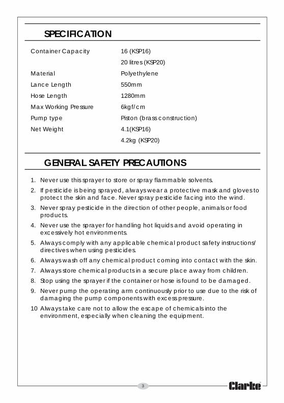
SPECIFICATION
Container Capacity 16 (KSP16)
20 litres (KSP20)
Material Polyethylene
Lance Length 550mm
Hose Length 1280mm
Max Working Pressure 6kgf/cm
Pump type Piston (brass construction)
Net Weight 4.1(KSP16)
4.2kg (KSP20)
GENERAL SAFETY PRECAUTIONS
1. Never use this sprayer to store or spray flammable solvents.
2. If pesticide is being sprayed, always wear a protective mask and gloves toprotect the skin and face. Never spray pesticide facing into the wind.
3. Never spray pesticide in the direction of other people, animals or foodproducts.
4. Never use the sprayer for handling hot liquids and avoid operating inexcessively hot environments.
5. Always comply with any applicable chemical product safety instructions/directives when using pesticides.
6. Always wash off any chemical product coming into contact with the skin.
7. Always store chemical products in a secure place away from children.
8. Stop using the sprayer if the container or hose is found to be damaged.
9. Never pump the operating arm continuously prior to use due to the risk ofdamaging the pump components with excess pressure.
10 Always take care not to allow the escape of chemicals into theenvironment, especially when cleaning the equipment.
4
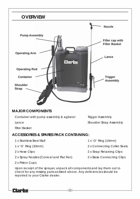
OVERVIEW
MAJOR COMPONENTSContainer with pump assembly & agitator Trigger Assembly
Lance Shoulder Strap Assembly
Filter Basket
ACCESSORIES & SPARES PACK CONTAINING:1 x Stainless Steel Ball 1 x ‘O’ Ring (14mm)
1 x ‘O’ Ring (33mm) 2 x Connecting Collet Seals
2 x Hose Clips 2 x Strap Retaining Clips
2 x Spray Nozzles (Conical and Flat Fan) 2 x Base Connecting Clips
2 x Piston Cups
Upon receipt of the sprayer, unpack all components and lay them out tocheck for any missing parts as listed above. Any deficiencies should bereported to your Clarke dealer.
Pump Assembly
ShoulderStrap
Operating Rod
Filler cap withFilter Basket
TriggerAssembly
Operating Arm
Container
Lance
Nozzle
5
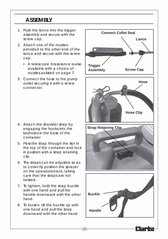
ASSEMBLY
1. Push the lance into the triggerassembly and secure with thescrew cap.
2. Attach one of the nozzlesprovided to the other end of thelance and secure with the screwcap.
• A telescopic brass lance is alsoavailable with a choice ofnozzles as listed on page 7.
3. Connect the hose to the pumpoutlet securing it with a screwconnector.
4. Attach the shoulder strap byengaging the hooks into thekeyholes in the base of thecontainer.
5. Pass the strap through the slot inthe top of the container and lockin position with a strap retainingclip.
6. The straps can be adjusted so asto correctly position the sprayeron the operators back, takingcare that the straps are nottwisted.
7. To tighten, hold the strap bucklewith one hand and pull thehandle downward with the otherhand.
8. To loosen, tilt the buckle up withone hand and pull the strapdownward with the other hand.
Strap Retaining Clip
Buckle
Handle
Screw Cap
Connect Collet Seal
TriggerAssembly
Lance
Hose Clip
Hose
6
OPERATION
1. Unscrew the filler cap and ensure the filter is in place.
2. Fill the container with the required liquid up to the desired graduation onthe side and replace the filler cap.
3. Pump the operating arm a fewtimes to pressurise the containeruntil the action of the pumpstiffens
4. Squeeze the trigger of the spraygun to start spraying. If sprayingcontinuously, squeeze the triggerand engage the trigger lock bypushing it forward.
5. Pump the operating arm tomaintain pressure.
6. Secure the operating arm in its retaining clip when not in use. Likewiseattach the lance to the clip on the operating arm.
MAINTENANCE
AFTER USEAfter use, the sprayer should be flushed thoroughly with clean water until thedischarge runs clear, to avoid the possibility of blockages from productresidue, or any cross-contamination between different products.
After extensive use, unscrew thetrigger body and remove and cleanthe filter fitted inside the triggerassembly.
If not used for long periods or usedcontinuously for several days, add alight smear of vaseline to the pistoncups and other moving parts toreduce wear and assist freemovement. Store in a cool place outof reach of children.
Trigger Lock
Trigger Body
Filter
7
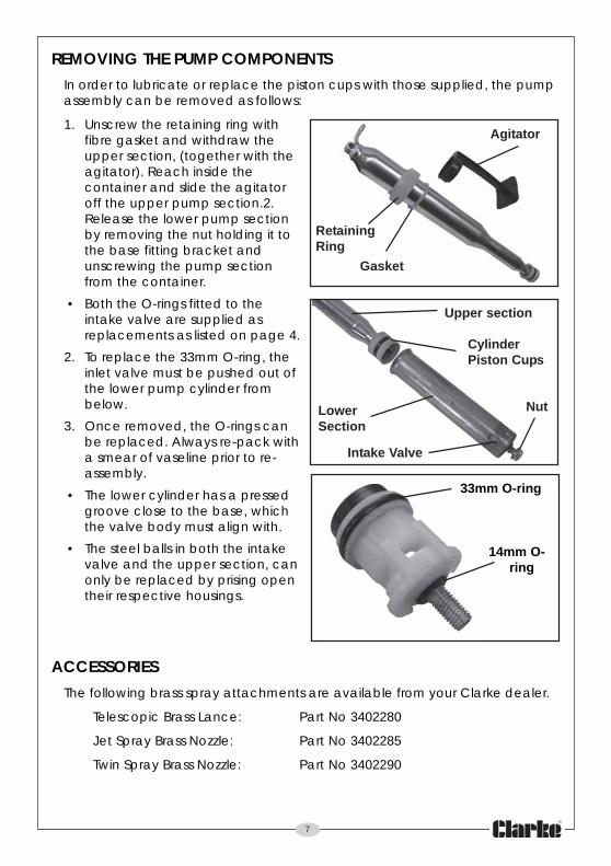
REMOVING THE PUMP COMPONENTSIn order to lubricate or replace the piston cups with those supplied, the pumpassembly can be removed as follows:
1. Unscrew the retaining ring withfibre gasket and withdraw theupper section, (together with theagitator). Reach inside thecontainer and slide the agitatoroff the upper pump section.2.Release the lower pump sectionby removing the nut holding it tothe base fitting bracket andunscrewing the pump sectionfrom the container.
• Both the O-rings fitted to theintake valve are supplied asreplacements as listed on page 4.
2. To replace the 33mm O-ring, theinlet valve must be pushed out ofthe lower pump cylinder frombelow.
3. Once removed, the O-rings canbe replaced. Always re-pack witha smear of vaseline prior to re-assembly.
• The lower cylinder has a pressedgroove close to the base, whichthe valve body must align with.
• The steel balls in both the intakevalve and the upper section, canonly be replaced by prising opentheir respective housings.
ACCESSORIESThe following brass spray attachments are available from your Clarke dealer.
Telescopic Brass Lance: Part No 3402280
Jet Spray Brass Nozzle: Part No 3402285
Twin Spray Brass Nozzle: Part No 3402290
Upper section
CylinderPiston Cups
LowerSection
Nut
Intake Valve
33mm O-ring
14mm O-ring
Agitator
RetainingRing
Gasket
8
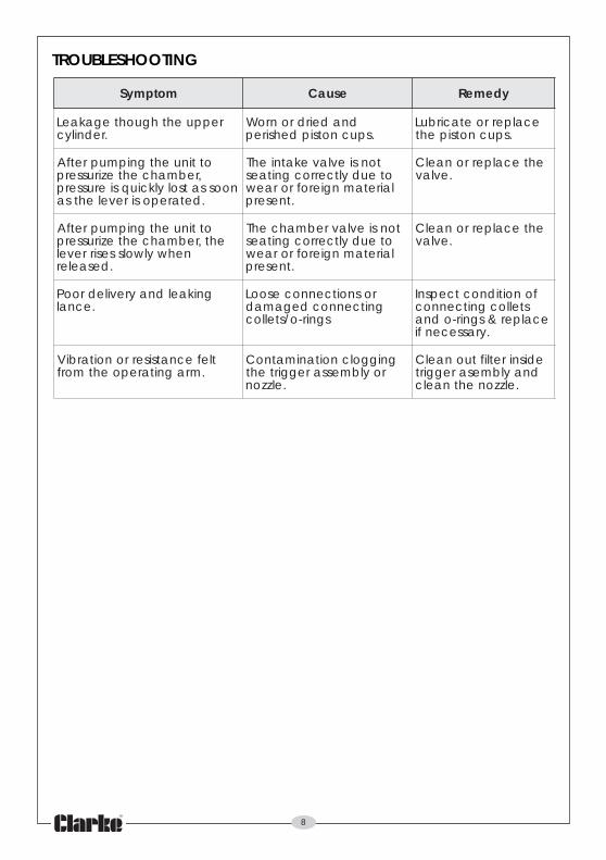
motpmyS esuaC ydemeR
reppuehthguohtegakaeL.rednilyc
dnadeirdronroW.spucnotsipdehsirep
ecalperroetacirbuL.spucnotsipeht
ottinuehtgnipmupretfA,rebmahcehtezirusserp
noossatsolylkciuqsierusserp.detareposirevelehtsa
tonsievlavekatniehToteudyltcerrocgnitaeslairetamngierofroraew
.tneserp
ehtecalperronaelC.evlav
ottinuehtgnipmupretfAeht,rebmahcehtezirusserp
nehwylwolssesirrevel.desaeler
tonsievlavrebmahcehToteudyltcerrocgnitaeslairetamngierofroraew
.tneserp
ehtecalperronaelC.evlav
gnikaeldnayreviledrooP.ecnal
rosnoitcennocesooLgnitcennocdegamad
sgnir-o/stelloc
fonoitidnoctcepsnIstellocgnitcennoc
ecalper&sgnir-odna.yrassecenfi
tlefecnatsiserronoitarbiV.mragnitarepoehtmorf
gniggolcnoitanimatnoCroylbmessareggirteht
.elzzon
edisniretliftuonaelCdnaylbmesareggirt
.elzzonehtnaelc
TROUBLESHOOTING
9
oN noitpircseD oN noipircseD
1 teSpilC-R&rehsaW 43 pilChtiwpirgdnaH
2 pilCesoHwercS 53 mrAgnitarepO
3 rotcennoCwercScitsalP 63 )14-73smeti(esaBreniatnoC
4 ylbmessAecnaLyarpS 73 pilCgnitcennoCesaB
5 gniRgniniateR 83 esaBtilpS
6 teksaGerbiF 93 pilcriC
7 woblEelzzoN 04 tfahstovipw/ctekcarBgnittiFesaB
8 rebmahCpmuPreppU 14 a/N
9 puCnotsiP 24 reniatnoC
01 recapSpuCnotsiP 34 reniartS
11 evlaVrebmahCpmuPreppU 44 marhpaiDdiL
21 ylbmessAecnaL 54 marhpaiDhtiwdiL
31 ylbmessAreggirT 64 eldnaHreggirT
41 0531x"61/5esoH 74 08xaid21retliF
51 doRgnitarepO 84 reggirT
61 a/N 94 a/N
71 )26-16&22-81smeti(ylbmessApartS 05 a/N
81 rotcetorPredluohS 15 ydoBelzzoN
91 mm059partS 25 wercS
02 retsujdA 35 )eulb(paCelzzoN
12 kooHpartS 45 paCevalVreggirT
22 kcoLpartS 55 ylbmessAeldeeNevlaVreggirT
32 rotatigA 65 gniR-O
42 )33-52smeti(ylbmessArednilyC 75 ydoBevlaVreggirT
52 rednilyCpmuPrewoL 85 rekcaPtelloC
62 llaBleetS 95 paCwercS
72 mm41laeSgniR-O 06 ebuTecnaL
82 )mm43(gniR-O 16 retsujdApartS
92 reniateRllaB 26 retsujdAhtiwpartS
03 a/N 36 yssAelzzoNenoCelbatsujdAeulB
13 a/N 46 paCelzzoN
23 )dutshtiw(ydoBevlaVekatnI
33 tuNdegnalF
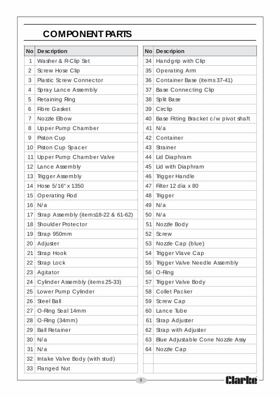
COMPONENT PARTS
10
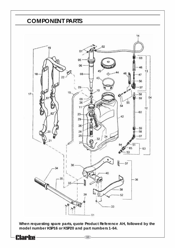
When requesting spare parts, quote Product Reference AH, followed by themodel number KSP16 or KSP20 and part numbers 1-64.
COMPONENT PARTS

11
NOTES
__________________________________________________________________________
__________________________________________________________________________
__________________________________________________________________________
__________________________________________________________________________
__________________________________________________________________________
__________________________________________________________________________
__________________________________________________________________________
__________________________________________________________________________
__________________________________________________________________________
__________________________________________________________________________
__________________________________________________________________________
__________________________________________________________________________
__________________________________________________________________________
__________________________________________________________________________