Embed Size (px)
Citation preview

Hancor, Inc. Drainage Handbook Specifications ♦ 1-2 ____________________________________________________________________________________________
Hancor, Inc., October, 2002
HANCOR BLUE SEALTM PIPE SPECIFICATIONS Scope This specification describes 12- through 60-inch (300 to 1500 mm) Hancor BLUE SEALTM pipe for use in gravity flow applications. Pipe Requirements BLUE SEALTM pipe shall have a smooth interior and annular exterior corrugations.
• 12- through 48-inch (300 to 1200 mm) shall meet AASHTO M294, Type S. • 60-inch (1500 mm) shall meet AASHTO MP 7, Type S. • Manning’s “n” value for use in design shall not be less than 0.010.
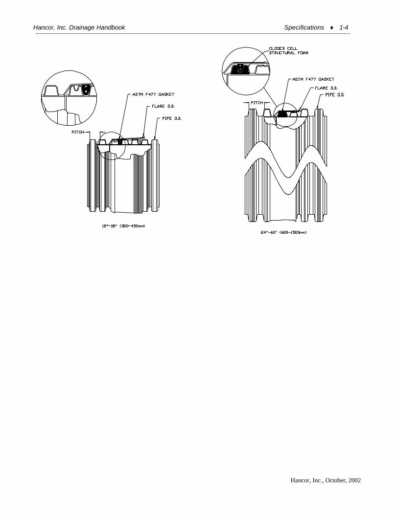
Joint Performance Pipe shall be joined with the BLUE SEALTM joint meeting the requirements of AASHTO M294, or AASHTO MP7. 12- through 60-inch (300 to 1500 mm) shall be watertight according to the requirements of ASTM D3212. Gaskets shall be made of polyisoprene meeting the requirements of ASTM F477 with the addition that the gaskets shall not have any visible cracking when tested according to ASTM D1149 after 72 hour exposure in 50 PPHM ozone at 104? ?Fahrenheit. Gaskets shall be installed by the pipe manufacturer and covered with a removable wrap to ensure the gasket is free from debris. 12- through 30-inch (300 to 750 mm) bells shall include a reinforcing rib at the flare O.D. to assure meeting roundness tolerances and enhance proper joint assembly. A joint lubricant available from the manufacturer shall be used on the gasket and bell during assembly. 24- through 60-inch (600 to 1500 mm) diameters shall have a reinforced bell & spigot including a bell tolerance device. The bell tolerance device shall be installed by the manufacture and covered with a protective wrap. The gasket corrugation shall be reinforced with a closed cell structural foam core. Watertight Field Test Performance To assure watertight field performance verification may be accomplished using ASTM F 1417 or ASTM C 969 test procedures. Appropriate safety precautions must be used when field testing any pipe material. Fittings Fittings shall conform to AASHTO M294 or AASHTO MP7. Fabricated fittings shall be welded at all accessible interior and exterior junctions. Material Properties Pipe and fitting material shall be high-density polyethylene meeting ASTM D3350 minimum cell classification 335400C. The pipe material shall be Hancor Resin 8™, which is a slow crack resistant material evaluated using the single point notched constant tensile load (SP-NCTL) test. Average SP-NCTL test specimens must exceed 24 hrs. with no test result less than 17 hrs. The closed cell structural foam core must have a free rise density no less than 3 lbs/ft3 and compressive strength no less than 20 lbs/in2. Quality Assurance All corrugated polyethylene pipe meeting or exceeding AASTHO M294 or MP7 shall only be provided by manufactures listed by the Plastics Pipe Institute (PPI) as having met the requirements of the PPI sponsored third-party certification program. All AASHTO M294 and MP7 pipe shall be clearly marked with a certification program mark or logo representing the supplied pipe is in compliance with all applicable standards. Installation Installation shall be in accordance with ASTM D2321, with the exception that minimum cover in trafficked areas for 12- through 48-inch (300 to 1200 mm) diameters shall be 1 ft. (0.3 m) and for 60-inch (1500 mm) diameter, the minimum cover shall be 1.5 ft. (0.5 m).
Hancor, Inc. Drainage Handbook Specifications ♦ 1-3 ____________________________________________________________________________________________
Hancor, Inc., October, 2002
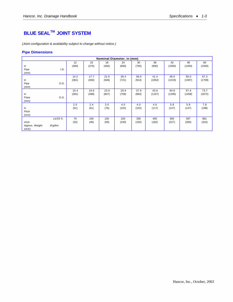
BLUE SEALTM JOINT SYSTEM (Joint configuration & availability subject to change without notice.)
Pipe Dimensions
Nominal Diameter, in (mm) in Pipe I.D. (mm)
12 (300)
15 (375)
18 (450)
24 (600)
30 (750)
36 (900)
42 (1050)
48 (1200)
60 (1500)
in Pipe O.D. (mm)
14.2 (361)
17.7 (450)
21.5 (546)
28.4 (721)
36.0 (914)
41.4 (1052)
48.0 (1219)
55.0 (1397)
67.3 (1709)
in Flare O.D. (mm)
15.4 (391)
19.6 (498)
23.9 (607)
29.9 (759)
37.9 (963)
43.6 (1107)
50.8 (1290)
57.4 (1458)
73.7 (1872)
in Pitch (mm)
2.0 (51)
2.4 (61)
3.0 (76)
4.0 (102)
4.0 (102)
4.6 (117)
5.8 (147)
5.8 (147)
7.8 (198)
Lb/20 ft. stick Approx. Weight (Kg/6m stick)
70 (32)
100 (46)
130 (59)
220 (100)
330 (150)
400 (182)
500 (227)
597 (260)
861 (315)
Hancor, Inc. Drainage Handbook Specifications ♦ 1-4 ____________________________________________________________________________________________
Hancor, Inc., October, 2002

Hancor, Inc. Drainage Handbook Specifications ♦ 1-5 ____________________________________________________________________________________________
Hancor, Inc., October, 2002
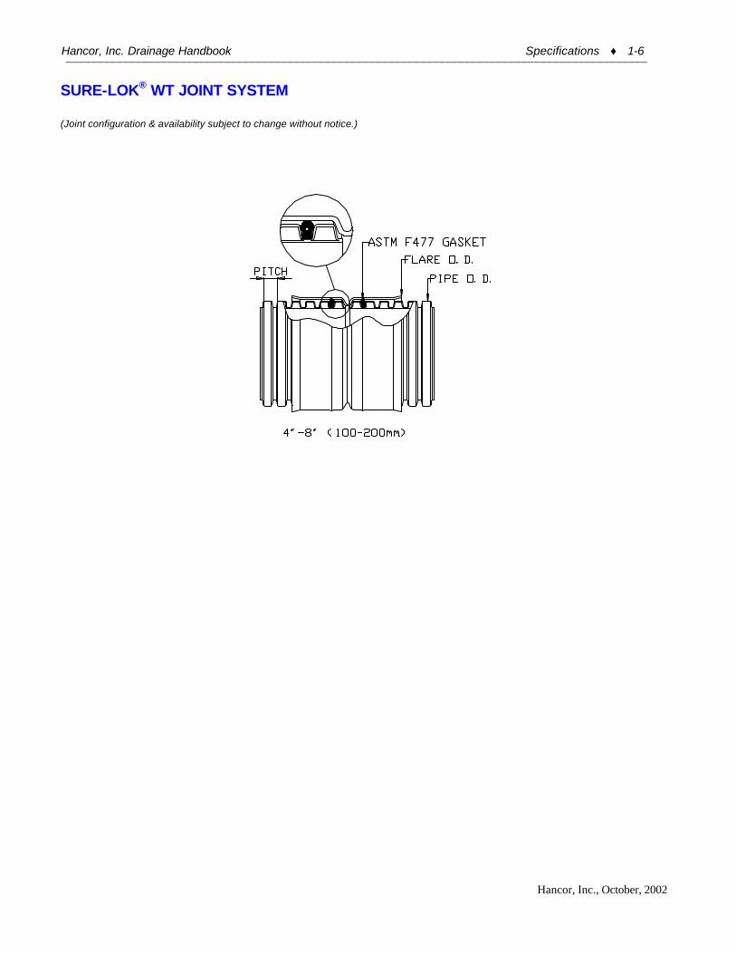
HANCOR SURE-LOK WT PIPE SPECIFICATIONS Scope This specification describes 4- through 8-inch (100 to 200 mm) Hancor Sure-Lok WT pipe for use in non-pressure drainage applications. Pipe Requirements Sure-Lok WT pipe shall have a smooth interior and annular exterior corrugations. • 4- to 8-inch (100 to 200 mm) shall meet AASHTO M252, Type S. • Manning’s “n” value for use in design shall not be less than 0.010. Joint Performance Pipe shall be joined with the Sure-Lok joint meeting the requirements of AASHTO M252. The joint shall be watertight according to the laboratory requirements of ASTM D3212. Joints shall remain watertight when subjected to a 1.5 degree axial misalignment. Gaskets shall be made of polyisoprene meeting the requirements of ASTM F477 with the addition that the gaskets shall not have any visible cracking when tested according to ASTM D1149 after 72 hour exposure in 50 PPHM ozone at 104° F (40° C). Gaskets shall be installed by the pipe manufacturer and covered with a removable wrap to ensure the gasket is free from debris. A joint lubricant supplied by the manufacturer shall be used on the gasket and bell during assembly. Fittings 4” – 8” (100 – 200 mm) fittings shall conform to AASHTO M252. Material Properties Pipe and fitting material shall be high density polyethylene meeting ASTM D3350 minimum cell classification 324420C for 4- through 8-inch (100 to 200 mm) diameters. Installation Installation shall be in accordance with ASTM D2321 with the exception that minimum cover in trafficked areas shall be one-foot (0.3 m). Pipe Dimensions
Nominal Pipe I.D. in (mm)
4 (100)
6 (150)
8 (200)
Approx. Pipe O.D. in (mm)
4.7 (119)
6.9 (175)
9.4 (239)
Approx. Pitch in (mm)
0.6 (16)
0.7 (19)
1.0 (26)
Approx. Weight* Lb/20 ft stick (kg/6m stick)
10 (5)
20 (9)
30 (14)
Perforations All diameters available with or without perforations
*One stick is 20’ (6m) for 4” – 8” (100 – 200 mm) diameter pipe. *Check with sales representative for availability.
Hancor, Inc. Drainage Handbook Specifications ♦ 1-6 ____________________________________________________________________________________________
Hancor, Inc., October, 2002
SURE-LOK® WT JOINT SYSTEM (Joint configuration & availability subject to change without notice.)
Hancor, Inc. Drainage Handbook Specifications ♦ 1-7 ____________________________________________________________________________________________
Hancor, Inc., October, 2002
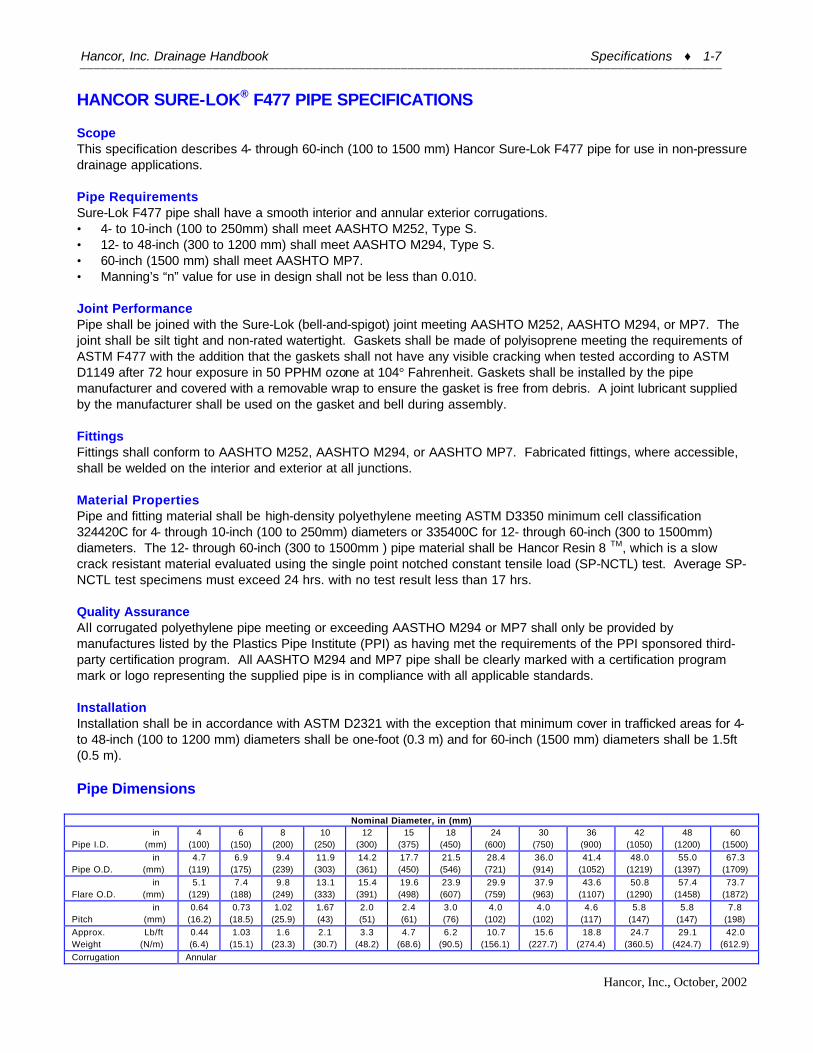
HANCOR SURE-LOK® F477 PIPE SPECIFICATIONS Scope This specification describes 4- through 60-inch (100 to 1500 mm) Hancor Sure-Lok F477 pipe for use in non-pressure drainage applications. Pipe Requirements Sure-Lok F477 pipe shall have a smooth interior and annular exterior corrugations. • 4- to 10-inch (100 to 250mm) shall meet AASHTO M252, Type S. • 12- to 48-inch (300 to 1200 mm) shall meet AASHTO M294, Type S. • 60-inch (1500 mm) shall meet AASHTO MP7. • Manning’s “n” value for use in design shall not be less than 0.010. Joint Performance Pipe shall be joined with the Sure-Lok (bell-and-spigot) joint meeting AASHTO M252, AASHTO M294, or MP7. The joint shall be silt tight and non-rated watertight. Gaskets shall be made of polyisoprene meeting the requirements of ASTM F477 with the addition that the gaskets shall not have any visible cracking when tested according to ASTM D1149 after 72 hour exposure in 50 PPHM ozone at 104° Fahrenheit. Gaskets shall be installed by the pipe manufacturer and covered with a removable wrap to ensure the gasket is free from debris. A joint lubricant supplied by the manufacturer shall be used on the gasket and bell during assembly. Fittings Fittings shall conform to AASHTO M252, AASHTO M294, or AASHTO MP7. Fabricated fittings, where accessible, shall be welded on the interior and exterior at all junctions. Material Properties Pipe and fitting material shall be high-density polyethylene meeting ASTM D3350 minimum cell classification 324420C for 4- through 10-inch (100 to 250mm) diameters or 335400C for 12- through 60-inch (300 to 1500mm) diameters. The 12- through 60-inch (300 to 1500mm ) pipe material shall be Hancor Resin 8 TM, which is a slow crack resistant material evaluated using the single point notched constant tensile load (SP-NCTL) test. Average SP-NCTL test specimens must exceed 24 hrs. with no test result less than 17 hrs. Quality Assurance All corrugated polyethylene pipe meeting or exceeding AASTHO M294 or MP7 shall only be provided by manufactures listed by the Plastics Pipe Institute (PPI) as having met the requirements of the PPI sponsored third-party certification program. All AASHTO M294 and MP7 pipe shall be clearly marked with a certification program mark or logo representing the supplied pipe is in compliance with all applicable standards. Installation Installation shall be in accordance with ASTM D2321 with the exception that minimum cover in trafficked areas for 4- to 48-inch (100 to 1200 mm) diameters shall be one-foot (0.3 m) and for 60-inch (1500 mm) diameters shall be 1.5ft (0.5 m). Pipe Dimensions
Nominal Diameter, in (mm) in Pipe I.D. (mm)
4 (100)
6 (150)
8 (200)
10 (250)
12 (300)
15 (375)
18 (450)
24 (600)
30 (750)
36 (900)
42 (1050)
48 (1200)
60 (1500)
in Pipe O.D. (mm)
4.7 (119)
6.9 (175)
9.4 (239)
11.9 (303)
14.2 (361)
17.7 (450)
21.5 (546)
28.4 (721)
36.0 (914)
41.4 (1052)
48.0 (1219)
55.0 (1397)
67.3 (1709)
in Flare O.D. (mm)
5.1 (129)
7.4 (188)
9.8 (249)
13.1 (333)
15.4 (391)
19.6 (498)
23.9 (607)
29.9 (759)
37.9 (963)
43.6 (1107)
50.8 (1290)
57.4 (1458)
73.7 (1872)
in Pitch (mm)
0.64 (16.2)
0.73 (18.5)
1.02 (25.9)
1.67 (43)
2.0 (51)
2.4 (61)
3.0 (76)
4.0 (102)
4.0 (102)
4.6 (117)
5.8 (147)
5.8 (147)
7.8 (198)
Approx. Lb/ft Weight (N/m)
0.44 (6.4)
1.03 (15.1)
1.6 (23.3)
2.1 (30.7)
3.3 (48.2)
4.7 (68.6)
6.2 (90.5)
10.7 (156.1)
15.6 (227.7)
18.8 (274.4)
24.7 (360.5)
29.1 (424.7)
42.0 (612.9)
Corrugation Annular
Hancor, Inc. Drainage Handbook Specifications ♦ 1-8 ____________________________________________________________________________________________
Hancor, Inc., October, 2002
Perforations All diameters available with or without perforations

Hancor, Inc. Drainage Handbook Specifications ♦ 1-9 ____________________________________________________________________________________________
Hancor, Inc., October, 2002
SURE-LOK® F477 PIPE JOINING SYSTEM (Joint configuration & availability subject to change without notice.)
4"-8" (100-200mm) 10"-18" (250-450mm)
24"-60" (600-1500mm)
Pipe O.D. Flare O.D.
ASTM F477 Gasket
Pitch

Hancor, Inc. Drainage Handbook Specifications ♦ 1-10 ____________________________________________________________________________________________
Hancor, Inc., October, 2002
EcoFirstTM PIPE SPECIFICATIONS
Scope This specification describes 4- through 30-inch (100 to 750 mm) EcoFirst pipe for use in gravity flow drainage applications.
Pipe Requirements EcoFirst pipe shall have a smooth interior and annular exterior corrugations. • 4” to 8” (100 – 200 mm) shall meet structural requirements of AASHTO M252, Type S. • 12” to 30” (300 - 750 mm) shall meet structural requirements of AASHTO M294, Type S. • Manning’s “n” value for use in design shall not be less than 0.010.
Joint Performance Pipe shall meet the joint performance requirements of AASHTO M252 or M294. • 12” to 30” (300 - 750 mm) Bell & Spigot gasketed joints shall be silt-tight and non-rated watertight. Gaskets
shall be made of polyisoprene meeting the requirements of ASTM F477 with the addition that the gaskets shall not have any visible cracking when tested according to ASTM D1149 after 72-hour exposure in 50 PPHM ozone at 104° Fahrenheit (40°C). Gaskets shall be installed by the pipe manufacturer and covered with a removable wrap to ensure the gasket is free from debris. A joint lubricant available from the manufacturer shall be used on the gasket and bell during assembly.
• 4” to 30” (100 – 700 mm) Plain End Pipe shall be joined with external couplers, or coupling bands covering at least two full corrugations on each end of the pipe. Standard (non-gasketed) connections shall meet the soil-tightness requirements of the AASHTO Standard Specification for Highway Bridges, Section 26, paragraph 26.4.2.4(e).
Fittings Fabricated fittings shall be welded or fussed at all accessible interior and exterior junctions.
Material Properties Pipe and fitting material shall be high density polyethylene meeting ASTM D3350 minimum cell classification 322420C for 4- through 8-inch (100 to 200 mm) diameters or 335400C for 12- through 30-inch (300 to 750 mm) diameters. Four through 30-inch (100 to 700 mm) shall be Post-Industrial polyethylene.
Marking 12” to 30” (300 - 750 mm) Bell & Spigot pipe shall be clearly marked with a green identification band on the spigot end of the pipe, while 12” to 30” (300 - 750 mm) Plain End Pipe shall be marked with a green identification band located between the first and second corrugations of one end of the product.
Installation Installation shall be in accordance with ASTM D2321 with the exception that minimum cover in trafficked areas shall be one foot (0.3 m).
Pipe Dimensions
Nominal Diameter
in Pipe I.D. (mm)
4 (100)
6 (150)
8 (200)
12 (300)
15 (375)
18 (450)
24 (600)
30 (750)
in Pipe O.D. (mm)
4.7 (119)
6.9 (175)
9.4 (239)
14.2 (361)
17.7 (450)
21.5 (546)
28.4 (721)
36.0 (914)
in Pitch (mm)
0.64 (16.2)
0.73 (18.5)
1.02 (25.9)
2.0 (51)
2.4 (61)
3.0 (76)
4.0 (102)
4.0 (102)
lbs/ft Approx. Weight (n/m)
0.44 (6.4)
1.03 (15.1)
1.6 (23.3)
3.3 (48.2)
4.7 (68.6)
6.2 (90.5)
10.7 (156.1)
15.6 (227.7)

Hancor, Inc. Drainage Handbook Specifications ♦ 1-11 ____________________________________________________________________________________________
Hancor, Inc., October, 2002
EcoFirstTM JOINT SYSTEM (Joint configuration & availability subject to change without notice.) EcoFirstTM Bell and Spigot Joining Systems
EcoFirstTM Plain End Joining Systems
O.D I.D.
Hancor, Inc. Drainage Handbook Specifications ♦ 1-12 ____________________________________________________________________________________________
Hancor, Inc., October, 2002
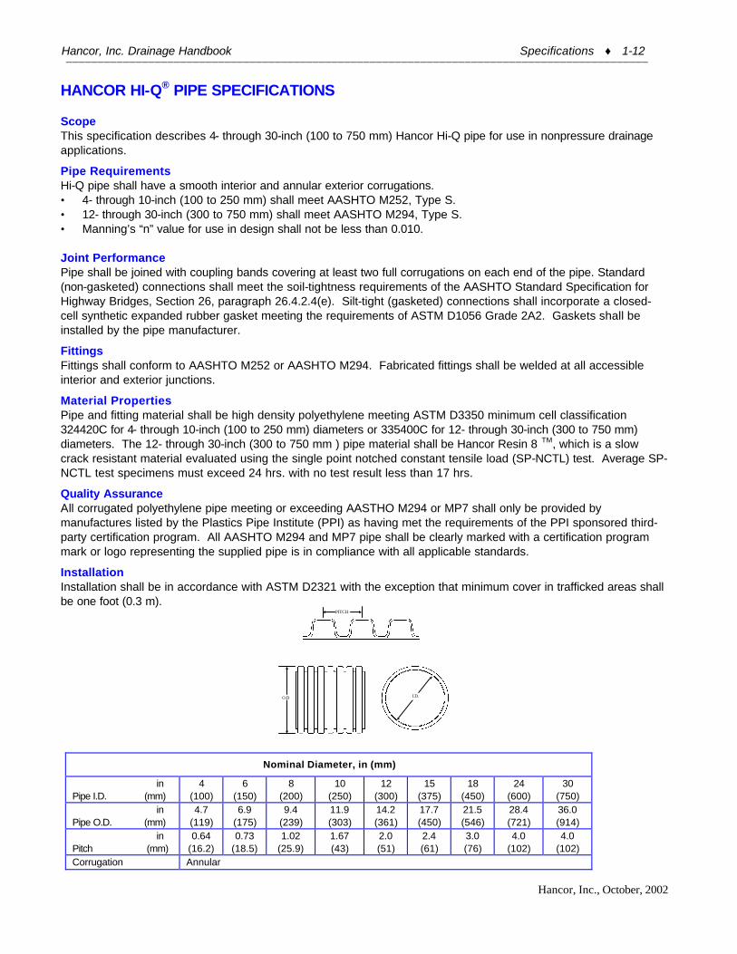
HANCOR HI-Q® PIPE SPECIFICATIONS Scope This specification describes 4- through 30-inch (100 to 750 mm) Hancor Hi-Q pipe for use in nonpressure drainage applications.
Pipe Requirements Hi-Q pipe shall have a smooth interior and annular exterior corrugations. • 4- through 10-inch (100 to 250 mm) shall meet AASHTO M252, Type S. • 12- through 30-inch (300 to 750 mm) shall meet AASHTO M294, Type S. • Manning’s “n” value for use in design shall not be less than 0.010. Joint Performance Pipe shall be joined with coupling bands covering at least two full corrugations on each end of the pipe. Standard (non-gasketed) connections shall meet the soil-tightness requirements of the AASHTO Standard Specification for Highway Bridges, Section 26, paragraph 26.4.2.4(e). Silt-tight (gasketed) connections shall incorporate a closed-cell synthetic expanded rubber gasket meeting the requirements of ASTM D1056 Grade 2A2. Gaskets shall be installed by the pipe manufacturer.
Fittings Fittings shall conform to AASHTO M252 or AASHTO M294. Fabricated fittings shall be welded at all accessible interior and exterior junctions.
Material Properties Pipe and fitting material shall be high density polyethylene meeting ASTM D3350 minimum cell classification 324420C for 4- through 10-inch (100 to 250 mm) diameters or 335400C for 12- through 30-inch (300 to 750 mm) diameters. The 12- through 30-inch (300 to 750 mm ) pipe material shall be Hancor Resin 8 TM, which is a slow crack resistant material evaluated using the single point notched constant tensile load (SP-NCTL) test. Average SP-NCTL test specimens must exceed 24 hrs. with no test result less than 17 hrs.
Quality Assurance All corrugated polyethylene pipe meeting or exceeding AASTHO M294 or MP7 shall only be provided by manufactures listed by the Plastics Pipe Institute (PPI) as having met the requirements of the PPI sponsored third-party certification program. All AASHTO M294 and MP7 pipe shall be clearly marked with a certification program mark or logo representing the supplied pipe is in compliance with all applicable standards.
Installation Installation shall be in accordance with ASTM D2321 with the exception that minimum cover in trafficked areas shall be one foot (0.3 m).
O.D
PITCH
I.D.
Nominal Diameter, in (mm)
in Pipe I.D. (mm)
4 (100)
6 (150)
8 (200)
10 (250)
12 (300)
15 (375)
18 (450)
24 (600)
30 (750)
in Pipe O.D. (mm)
4.7 (119)
6.9 (175)
9.4 (239)
11.9 (303)
14.2 (361)
17.7 (450)
21.5 (546)
28.4 (721)
36.0 (914)
in Pitch (mm)
0.64 (16.2)
0.73 (18.5)
1.02 (25.9)
1.67 (43)
2.0 (51)
2.4 (61)
3.0 (76)
4.0 (102)
4.0 (102)
Corrugation Annular

Hancor, Inc. Drainage Handbook Specifications ♦ 1-13 ____________________________________________________________________________________________
Hancor, Inc., October, 2002
Perforations All diameters available with or without perforations

Hancor, Inc. Drainage Handbook Specifications ♦ 1-14 ____________________________________________________________________________________________
Hancor, Inc., October, 2002
HANCOR AASHTO PIPE SPECIFICATION Scope This specification describes 3- through 24-inch (75 to 600 mm) Hancor AASHTO pipe for use in non-pressure drainage applications. Pipe Requirements Hancor AASHTO Pipe shall have annular interior and exterior corrugations.
• 3- through 10-inch (75 to 250 mm) pipe shall meet AASHTO M252 Type C • 12- through 24-inch (300 to 600 mm) shall meet AASHTO M294 Type C.
Joint Performance Pipe shall be joined with internal or external couplers, or coupling bands covering at least two full corrugations on each end of the pipe. Standard (non-gasketed) connections shall meet the soil-tightness requirements of the AASHTO Standard Specification for Highway Bridges, Section 26, paragraph 26.4.2.4(e). Silt-tight (gasketed) connections shall incorporate a closed-cell synthetic expanded rubber gasket meeting the requirements of ASTM D1056 Grade 2A2. Gaskets shall be installed on the connection by the pipe manufacturer. Fittings Fittings shall conform to AASHTO M252 or AASHTO M294. Material Properties Pipe and fitting material shall be high density polyethylene meeting ASTM D3350 minimum cell classification 324420C for 3- through 10-inch (75 to 250 mm) diameters or 335400C for 12- through 24-inch (300 to 600 mm). The 12- through 60-inch (300 to 1500mm ) pipe material shall be Hancor Resin 8 TM, which is a slow crack resistant material evaluated using the single point notched constant tensile load (SP-NCTL) test. Average SP-NCTL test specimens must exceed 24 hrs. with no test result less than 17 hrs. Installation Installation shall be in accordance with ASTM D2321 with the exception that minimum cover in trafficked areas shall be one foot (0.3 m).
Nominal Diameter, in. (mm)
in Pipe I.D. (mm)
3 (75)
4 (100)
6 (150)
8 (200)
10 (250)
12 (300)
15 (375)
18 (450)
24 (600)
in Pipe O.D. (mm)
3.6 (91)
4.6 (117)
7.0 (178)
9.5 (241)
12.0 (305)
14.2 (361)
17.7 (450)
21.5 (546)
28.4 (721)
in Pitch (mm)
0.7 (18)
0.7 (18)
0.7 (18)
1.0 (25)
1.6 (41)
2.0 (51)
2.4 (61)
3.0 (76)
4.0 (102)
Corrugation Annular
Perforations All diameters available with or without perforations.

Hancor, Inc. Drainage Handbook Specifications ♦ 1-15 ____________________________________________________________________________________________
Hancor, Inc., October, 2002
HANCOR HEAVY DUTY PIPE SPECIFICATION Scope This specification describes 3- through 24-inch (75 to 600 mm) Hancor Heavy Duty pipe for use in non-pressure drainage applications. Pipe Requirements Hancor Heavy Duty pipe shall have annular interior and exterior corrugations.
• 3- through 6-inch (75 to150 mm) shall meet ASTM F405; • 8- through 24-inch (200 to 600 mm) shall meet ASTM F667.
Joint Performance Pipe shall be joined with internal or external couplers, or coupling bands covering at least two full corrugations on each end of the pipe. Standard (non-gasketed) connections shall meet the soil-tightness requirements of the AASHTO Standard Specification for Highway Bridges, Section 26, paragraph 26.4.2.4(e). Silt-tight (gasketed) connections shall incorporate a closed-cell synthetic expanded rubber gasket meeting the requirements of ASTM D1056 Grade 2A2. Gaskets shall be installed on the connection by the pipe manufacturer. Fittings Fittings shall conform to ASTM F405 or ASTM F667. Material Properties Pipe and fitting material shall be high density polyethylene meeting the testing requirements of ASTM D3350 minimum cell classification 324420C; or ASTM D1248 Type III, Class C, Category 4, Grade P33. Installation Installation shall be in accordance with ASTM D2321 with the exception that minimum cover in trafficked areas shall be one foot (0.3m).
Nominal Diameter, in. (mm)
in Pipe I.D. (mm)
3 (75)
4 (100)
5 (125)
6 (150)
8 (200)
10 (250)
12 (300)
15 (375)
18 (450)
24 (600)
in Pipe O.D. (mm)
3.6 (91)
4.6 (117)
5.9 (150)
7.0 (178)
9.5 (241)
12.0 (305)
14.2 (361)
17.7 (450)
21.5 (546)
28.4 (721)
in Pitch (mm)
0.7 (18)
0.7 (18)
0.7 (18)
0.7 (18)
1.0 (25)
1.6 (41)
2.0 (51)
2.4 (61)
3.0 (76)
4.0 (102)
Corrugation Annular
Perforations All diameters available with or without perforations.

Hancor, Inc. Drainage Handbook Specifications ♦ 1-16 ____________________________________________________________________________________________
Hancor, Inc., October, 2002
HANCOR SMOOTHWALL SEWER & DRAIN PIPE SPECIFICATIONS Scope This specification describes Hancor Smoothwall Sewer & Drain pipe in 3- through 6-inch (75 to 150 mm) diameters for use in nonpressure drainage and leachfield applications. Pipe Requirements Hancor Smoothwall Sewer & Drain pipe shall meet the requirements of ASTM F810. It shall have a smooth interior and exterior. Manning's "n" value for use in design shall not be less than 0.009. Joint Performance Pipe joints shall be bell-and-spigot. Bell ends shall be integrally formed on the pipe at one end to form a soil-tight connection. Material Properties Pipe material shall be high density polyethylene meeting ASTM D3350 minimum cell classification 324420C or E; or ASTM D1248 Type III, Class B or C, Category 4, Grade P33. Installation For nonpressure drainage applications, installation shall be in accordance with ASTM D2321 with the exception that minimum cover in trafficked areas shall be one foot (0.3 m). For leachfield applications, installation shall be in accordance with ASTM F481 and as regulated by regional, state, and local agencies. Proper authorization for specific applications and designs should be obtained prior to installation to ensure suitability in certain locales.
Nominal Diameter, in. (mm)
in Pipe I.D. (mm)
3 (75)
4 (100)
6 (150)
in Pipe O.D. (mm)
3.25 (83)
4.215 (107)
6.275 (159)
Perforations All diameters available with or without perforations
White Skin Black Core
O.D.
I.D.
Bell End Spigot

Hancor, Inc. Drainage Handbook Specifications ♦ 1-17 ____________________________________________________________________________________________
Hancor, Inc., October, 2002
HANCOR CHANNEL-FLOW® PIPE SPECIFICATIONS Scope This specification describes Hancor Channel-Flow pipe in 4-inch (100 mm) diameter for use in on-site waste applications. Pipe Requirements Hancor Channel-Flow pipe shall meet the requirements of ASTM F405 and SCS 606. It shall have a corrugated interior and corrugated exterior. Perforations shall be spaced every 4.2 inches (1.7 mm) on the length of the pipe. There shall be three perforation options *. Option 1: perforation pattern shall have three ½” diameter holes, 60 degrees apart with no rotation in the bottom 120 degrees of the pipe channel. Option 2: perforation pattern shall have two ½” diameter holes spaced 120 degrees apart with no rotation in the bottom of the pipe channel. Option 3: perforation pattern shall have three ½” diameter holes spaced 120 degrees apart with no rotation. *Note: Check with sales representative for perforation option availability by area. Joint Performance Pipe shall be joined with self-coupling stubs located at the ends of each pipe section. Fittings Fittings shall conform to ASTM F405. Material Properties Pipe material shall be high density polyethylene meeting the requirements of ASTM D3350 minimum cell classification 324420C; or ASTM D1248 Type III, Class C, Category 4, Grade P33. Installation Installation shall be in accordance with ASTM F481and those issued by the local health department.
Perforation Options

Hancor, Inc. Drainage Handbook Specifications ♦ 1-18 ____________________________________________________________________________________________
Hancor, Inc., October, 2002
HANCOR CHANNEL-MUCK PIPE SPECIFICATIONS Scope This specification describes Hancor Channel-Muck pipe in 4-inch (100 mm), 5-inch (125 mm), and 6 inch (150 mm) diameters for use in agricultural drainage applications. Pipe Requirements Hancor Channel-Muck pipe shall meet the requirements of ASTM F405 and SCS 606. It shall have a corrugated interior and corrugated exterior. There shall be three perforations every 4.2 inch (106 mm) on the length of the pipe. The perforations shall be ¾ inch (19 mm) holes, 120 degrees apart with no rotation. Joint Performance Pipe shall be joined with self-coupling stubs located every 4.2 inch (106 mm) on the length of the pipe. Fittings Fittings shall conform to ASTM F405. Material Properties Pipe material shall be high density polyethylene meeting the requirements of ASTM D3350 minimum cell classification 324420C; or ASTM D1248 Type III, Class C, Category 4, Grade P33. Installation Installation shall be in accordance with Hancor installation instructions and those issued by regional, state or local agencies.

Hancor, Inc. Drainage Handbook Specifications ♦ 1-19 ____________________________________________________________________________________________
Hancor, Inc., October, 2002
HANCOR GRAVELLESS PIPE SPECIFICATIONS Scope This specification describes Hancor Gravelless pipe available in 8- and 10-inch (200 and 250 mm) diameters for use in on-site waste disposal applications. Pipe Requirements Hancor Gravelless pipe shall meet the requirements of ASTM F667 and SCS606. It shall have a corrugated interior and corrugated exterior. There shall be 3/8 inch to ½ inch holes 120 degrees apart staggered one hole per corrugation on the length of the pipe. The 8 inch (200 mm) pipe shall have 2.65 square inches per foot of open area while the 10 inch (250 mm) pipe shall have 2.95 square inches of open area per foot. The pipe shall be supplied with a pre-installed filter fabric. Conforming to ASTM F667 specifications, the pipe stiffness at 5% deflection shall be 30 psi (210 kpa) and the impact resistance shall be 27.5ft. lbs. (37.3 N m) at 25 degrees F. Joint Performance Pipe shall be joined with internal or external couplers, or coupling bands covering at least two full corrugations on each end of the pipe. Fittings Fittings shall conform to ASTM F667. Material Properties Pipe material shall be high-density polyethylene meeting the requirements of ASTM D3350 minimum cell classification 324420C; or ASTM D1248 Type III, Class C, Category 4, Grade P33. Filter material shall be spunbonded nylon weighing 0.85oz.sy (ASTM D3776). The material shall be a white monofilament with a fiber size of 4.5 denier per filament. The material shall be 0.005 inches thick with a minimum Mullen Burst (ASTM D3786) of 23.6psi and Grab Strengths (ASTM D4632) in the machine direction and traverse direction 30lbs and 17.7lbs respectively. The material shall have an AOS (U.S. sieve) rating of 50 with an air permeability of 686 cfm per square foot (ASTM D1117). Installation Installation shall be in accordance with Hancor published installation instructions or those issued by a local health department.

Hancor, Inc. Drainage Handbook Specifications ♦ 1-20 ____________________________________________________________________________________________
Hancor, Inc., October, 2002
HANCOR DRAIN GRATE SPECIFICATION Scope This specification describes Hancor 12- and 15-inch (300 and 375 mm) Drain Grate for use in non-trafficked clean-out port and surface inlet applications. Drain Grate Requirements The Drain Grate shall be manufactured form high density polyethylene. The maximum load capacity shall be 1000 lbs. (454 kg). Installation Hancor 12- and 15-inch (300 and 375 inch (300 mm) drain grates are intended to work in conjunction with 12- and 15-inch (300 and 375 mm) Hancor Hi-Q drainage pipes respectively. The bottom lip of the drain grate shall be inserted into the end of the Hi-Q pipe section and then fastened to the pipe with four lag screws.
A B C D E F
12-inch (300 mm) drain grate
12 9/16” 14 ½” 3/8” 11 ¾” 14 ½” 1 7/8”
15-inch (375 mm) drain grate
16 ½” 18” 3/8” 14 11/16” 18” 2”
Warning: This product is furnished with four lag screws to be used as a fastening mechanism for proper installation. As well, this product has a maximum load capacity of 1000lbs (454kg) for the 12” drain grate and 1500lbs (681kg) for the 15” drain grate. Exceeding load capacity or poor installation may cause injury to persons and property.
A
B
C
E D
F

Hancor, Inc. Drainage Handbook Specifications ♦ 1-21 ____________________________________________________________________________________________
Hancor, Inc., October, 2002
HANCOR HI-Q® FLARED END SECTION SPECIFICATIONS Scope This specification describes 10- through 36-inch (250 to 900mm) Hi-Q Flared End Sections for use in culvert and drainage outlet applications. Requirements The invert of the pipe and the end section shall be at the same elevation. Hi-Q Flared End Section shall be high density polyethylene meeting ASTM D3350 minimum cell classification 213320C. Each end section shall have a carbon black additive for UV protection. The metal threaded fastener shall be stainless steel. Installation Installation shall be in accordance with Hancor installation instructions and with those issued by state or local authorities.
PIPE DIAMETER, in (mm)
in DIMENSION (mm)
10/12 (250/300)
15 (375)
18 (450)
24 (600)
30 (750)
36 (900)
in A (mm)
42 (1781)
41 (1738)
49 (2078)
59.5 (2523)
88 (3731)
88 (3731)
in B (mm)
14.5 (615)
19 (806)
22 (933)
28 (1187)
36 (1526)
43 (1823)
in C (mm)
33 (1399)
34 (1442)
43 (1823)
48 (2035)
63.5 (2692)
66.5 (2820)
in D (mm)
6 (254)
6 (254)
6 (254)
6 (254)
6 (254)
6 (254)
A
D
Toe Trough
Collar
C
B

Hancor, Inc. Drainage Handbook Specifications ♦ 1-22 ____________________________________________________________________________________________
Hancor, Inc., October, 2002
HANCOR METER PIT SPECIFICATION Scope This specification describes 18- and 21-inch (450 and 525mm) Meter Pit for use as meter enclosures. Requirements Hancor Meter Pits shall be white in color. Meter pits shall have a smooth interior and annular exterior corrugations. Based on ASTM D 2412 at 5% deflection the pipe stiffness for 18-inch (450 mm) and 21-inch (525 mm) Meter Pits shall be 40 pii (275 N/m/mm) and 34 pii (235 N/m/mm), respectively. The pits shall be available in 24, 30, 36, 48 inch, and 12 foot (0.6, 0.8, 0.9, 1.2, and 3.7 m) lengths. Meter Pits shall be notched at 0 and 180 degrees at the base to accommodate inlet and outlet pipes. Material Properties Meter pits shall be high density polyethylene meeting ASTM D3350 minimum cell classification 324420 B. Installation Installation shall be in accordance with Hancor installation instructions or those issued by regional, state, or local agencies. Nominal Dimensions
in Inner Diameter (mm)
18” (450)
21” (525)
in Outer Diameter (mm)
21.5” (546)
25” (635)
I.D.
O.D.
3.25" (83mm)
Length Varies
3" (76mm)
Hancor, Inc. Drainage Handbook Specifications ♦ 1-23 ____________________________________________________________________________________________
Hancor, Inc., October, 2002
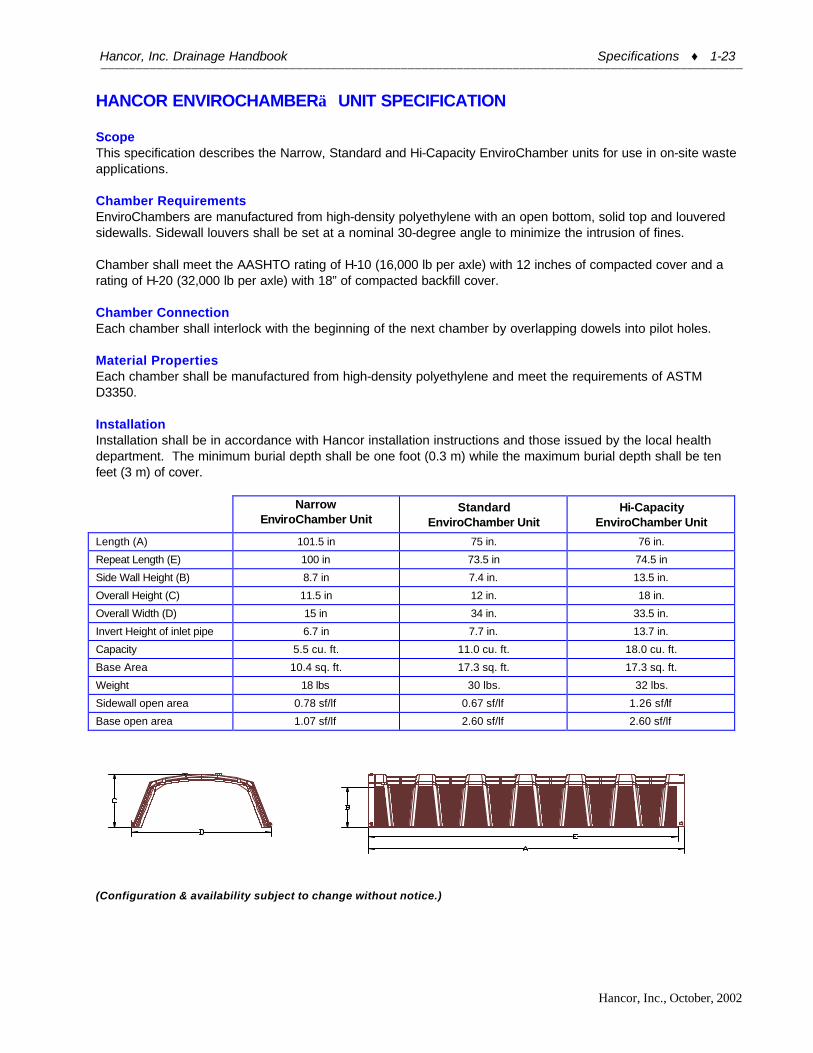
HANCOR ENVIROCHAMBER UNIT SPECIFICATION Scope This specification describes the Narrow, Standard and Hi-Capacity EnviroChamber units for use in on-site waste applications. Chamber Requirements EnviroChambers are manufactured from high-density polyethylene with an open bottom, solid top and louvered sidewalls. Sidewall louvers shall be set at a nominal 30-degree angle to minimize the intrusion of fines. Chamber shall meet the AASHTO rating of H-10 (16,000 lb per axle) with 12 inches of compacted cover and a rating of H-20 (32,000 lb per axle) with 18” of compacted backfill cover. Chamber Connection Each chamber shall interlock with the beginning of the next chamber by overlapping dowels into pilot holes. Material Properties Each chamber shall be manufactured from high-density polyethylene and meet the requirements of ASTM D3350. Installation Installation shall be in accordance with Hancor installation instructions and those issued by the local health department. The minimum burial depth shall be one foot (0.3 m) while the maximum burial depth shall be ten feet (3 m) of cover.
Narrow
EnviroChamber Unit Standard
EnviroChamber Unit Hi-Capacity
EnviroChamber Unit
Length (A) 101.5 in 75 in. 76 in.
Repeat Length (E) 100 in 73.5 in 74.5 in
Side Wall Height (B) 8.7 in 7.4 in. 13.5 in.
Overall Height (C) 11.5 in 12 in. 18 in.
Overall Width (D) 15 in 34 in. 33.5 in.
Invert Height of inlet pipe 6.7 in 7.7 in. 13.7 in.
Capacity 5.5 cu. ft. 11.0 cu. ft. 18.0 cu. ft.
Base Area 10.4 sq. ft. 17.3 sq. ft. 17.3 sq. ft.
Weight 18 lbs 30 lbs. 32 lbs.
Sidewall open area 0.78 sf/lf 0.67 sf/lf 1.26 sf/lf
Base open area 1.07 sf/lf 2.60 sf/lf 2.60 sf/lf
(Configuration & availability subject to change without notice.)

Hancor, Inc. Drainage Handbook Specifications ♦ 1-24 ____________________________________________________________________________________________
Hancor, Inc., October, 2002
HANCOR HEAVY DUTY DISTRIBUTION BOX SPECIFICATIONS Scope This specification describes Hancor Heavy Duty Distribution Box for use in on-site waste disposal applications. Unit Requirements The Heavy Duty Distribution Box shall have one inlet and accommodate up to seven outlets. The outlets shall be designed to accept 4 inch (100 mm) Channel-Flow and/or Smoothwall Sewer & Drain pipe, while the inlet shall provide a watertight connection for 4 inch (100 mm) Schedule 40 PVC or 4 inch (100 mm) Smoothwall. There shall be a flange located on the top of the box designed to accommodate 6 inch (150 mm) corrugated plastic tubing for use as a clean out and observation port. Material Properties Box material shall be high-density polyethylene meeting the requirements of ASTM D3350. Installation Installation shall be in accordance with Hancor installation instructions and those regulated by regional, state and local agencies.

Hancor, Inc. Drainage Handbook Specifications ♦ 1-25 ____________________________________________________________________________________________
Hancor, Inc., October, 2002
HANCOR MULTI-PURPOSE DISTRIBUTION SUMP SPECIFICATION Scope This specification describes Hancor’s Multi-Purpose Distribution Sump for use in both, on-site waste management and general drainage applications. Unit Requirements The Multi-Purpose Distribution Sump shall accommodate up to eight inlet/outlet lines. The outlets shall be designed to accept 4 inch (100mm) Channel-Flow and/or Smoothwall sewer and drain pipe, while the inlet shall provide a connection for SDR-25 dual wall tubing from septic tank. The sump shall be completely corrosion proof and acid, alkali and frost resistant. There shall be a molded-on lid on both ends of the distribution sump. The lids shall be designed so that they can be cut free from the main body and used as a locking lid. Once the lid is removed, there shall be an exposed flange located on the top of the sump designed to accommodate 8” corrugated plastic tubing for use as a clean out and observation port. Material Properties Sump material shall be high-density polyethylene meeting the requirements of ASTM D3350. Installation Installation shall be in accordance with Hancor installation instructions and those regulated by regional, state and local agencies

Hancor, Inc. Drainage Handbook Specifications ♦ 1-26 ____________________________________________________________________________________________
Hancor, Inc., October, 2002
HANCOR STANDARD ALTERNATOR VALVE SPECIFICATION Scope This specification describes Hancor’s Standard Alternator Valve for use in on-site waste disposal applications. Unit Requirements The Standard Alternator Valve shall have one inlet and two outlets. The outlets shall be designed to accept 4 inch (100mm) Channel-Flow tubing, while the inlet shall provide a connection for 4 inch (100 mm) Co-Extruded Smoothwall Sewer & Drain pipe. There shall be a flange located on the top of the box designed to accommodate 10 inch (250 mm) corrugated plastic tubing for use as a clean out and observation port. The kit shall be provided with an alternator paddle that is designed to allow controlled diversion of effluent to either of the two outlets. Material Properties Alternator Valve material shall be high-density polyethylene meeting the requirements of ASTM D3350. Installation Installation shall be in accordance with Hancor published installation instructions and those regulated by regional, state and local agencies Warning: This lid is furnished with two lag screws to be used as a fastening mechanism for proper installation. Failure to properly installation lid may cause injury to persons and property.

Hancor, Inc. Drainage Handbook Specifications ♦ 1-27 ____________________________________________________________________________________________
Hancor, Inc., October, 2002
HANCOR RADON DUAL PURPOSE VENTED SUMP SPECIFICATION Scope This specification describes Hancor’s Radon Dual Purpose Vented Sump System for use in residential drainage and ventilation of toxic or noxious gas applications. Requirements The Radon Dual Purpose Vented Sump shall be available in 14-gallon capacity. The sump well shall have three pre-formed inlet collars sized to fit 4 inch (100 mm) corrugated polyethylene drainage lines. Each well shall have a molded side panel designed to accept the outside basement perimeter line at any elevation along the well wall. The sump well shall be available with a pre-formed structural foam lid. The lid shall be pre-drilled to accept 4 inch (100 mm) or 3 inch (75 mm) vent and discharge pipes. Molded flanges with rubber o-rings for these pipes, as well as rubber pump wire plug shall be included. Material Properties Radon Dual Purpose Vented Sump shall be high-density polyethylene meeting ASTM D3350. Installation Installation shall be in accordance with Hancor installation instructions and those issued by regional, state, or local agencies.
A B C D E F G H 14-gallon 12”
305mm 8”
203mm 14 ¼” 362mm
4 ¾” 121mm
20 3/8” 518mm
18 1/8” 460mm
24” 610mm
20 7/8” 530mm
Items Included No. Qty. 1 1 14-gallon Sump Well 2 1 Radon Vented Sump
Lid 3 1 4” Neoprene gasket 4 1 Grommet 1¼” or 1½”
Sch 40 Neoprene 5 1 Stopper Size 11
Isoprene 6 8 Thumbscrew
¼-20 x 1 ¼ 7 16 Flatwasher ¼ 8 8 Hex Nut ¼ - 20 9 8 Foam Tape
1/8 inch x 1”

Hancor, Inc. Drainage Handbook Specifications ♦ 1-28 ____________________________________________________________________________________________
Hancor, Inc., October, 2002
HANCOR SEWAGE EJECTOR SUMP SPECIFICATION Scope This specification describes Hancor’s Sewage Ejector Sump System for use in residential drainage applications. Requirements The Sewage Ejector Sump shall be available in 19-gallon capacity. The sump well shall have one pre-drilled inlet hole with a flange adapter for standard 4 inch (100mm) sewer pipe. Each well shall have three molded side panels designed to accept an extra inlet line and flange at 90 degree increments around its circumference. The sump well shall come with a pre-formed structural foam lid. The lid shall be pre-drilled to accept 2 inch (50mm) or 3 inch (75mm) vent and discharge pipes. Molded flanges with rubber o-rings for these pipes, as well as rubber pump wire plug shall be included. Material Properties Sewage Ejector Sump shall be high density polyethylene meeting ASTM D3350. Installation Installation shall be in accordance with Hancor installation instructions and those issued by regional, state, or local agencies.
A B C D E F G H 19-
gallon 12”
304mm 13”
330mm 14 ¼” 361mm
4 ¾” 121mm
20 3/8” 518mm
24” 610mm
31 ¾” 806mm
20 7/8” 530mm

Hancor, Inc. Drainage Handbook Specifications ♦ 1-29 ____________________________________________________________________________________________
Hancor, Inc., October, 2002
HANCOR SUMP PUMP WELL SPECIFICATION Scope This specification describes Hancor’s sump pump well for use in residential drainage applications. Requirements The sump pump well shall be available in both 14-gallon and 19-gallon sizes. Each well shall have three pre-formed inlet collars sized to fit 4 inch (100mm) corrugated polyethylene drainage lines. Each well shall have a molded side panel designed to accept the outside basement perimeter line at any elevation along the well wall. Both wells shall have a twist-locking lid. Material Properties Sump pump wells shall be high density polyethylene meeting ASTM D3350. Installation Installation shall be in accordance with Hancor installation instructions and those issued by regional, state, or local agencies.
A B C D E F G H I J 14-
gallon 12”
305mm 8”
203mm 14 ¼” 362mm
4 ¾” 121mm
20 3/8” 518mm
18 1/8” 460mm
24” 610mm
20 7/8” 530mm
18 3/8” 467mm
20 ½” 521mm
19-gallon
12” 305mm
13” 330mm
14 ¼” 362mm
4 ¾” 121mm
20 3/8” 518mm
24” 610mm
31 ¾” 806mm
20 7/8” 530mm
18 3/8” 467mm
20 ½” 521mm

Hancor, Inc. Drainage Handbook Specifications ♦ 1-30 ____________________________________________________________________________________________
Hancor, Inc., October, 2002
HANCOR HI-Q® SLOPED END SECTION SPECIFICATIONS
Scope This specification describes 12- through 60-inch (300 to 1500mm) Sloped End Sections for use in culvert and drainage outlet applications. Requirements The invert of the pipe and the end section shall be at the same elevation. Sloped End Section shall be high-density polyethylene meeting ASTM D3350 minimum cell classification 335400C. Each end section shall have a carbon black additive for UV protection. Installation Installation shall be in accordance with Hancor installation instructions and with those issued by state or local authorities.
Dimensions Slope x:1 Slope 2:1 Slope 3:1 Slope 4:1 Slope 6:1
Pipe Dia. (in)
A* (in)
C** (in)
D (in)
B (in)
OAL (in)
B (in)
OAL (in)
B (in)
OAL (in)
B (in)
OAL (in)
12 8 3 3 12 20 18 26 24 32 36 44 15 9.7 4 4 14.8 24.5 22 31.9 29.4 39.1 41.6 51.4 18 12 4.2 4 21 33 30 42 39 51 60 72 24 16 6 6 24 40 36 52 48 64 72 88 30 16 6 6 36 52 56 72 72 88 108 124 36 18.5 6.9 6 48.1 64.6 73.9 92.3 96.9 115.4 42 17.5 5.2 6 64.4 82 93.6 111.3 122.9 140.5 48 17.5 5.4 6 76.1 93.6 111.2 128.7 146.4 163.9 60 23.2 3.6 6 100.6 123.9
* The “A” length for 12-36” is 4 corrugations and for 42-60” is 3 corrugations ** The “C” dimension varies slightly for some diameters depending on the slope
Note: Hancor recommends that the product be installed with a concrete collar/edge to support and close corrugations per DOT specifications. The Channel at the bottom of the taper must be shaped to prevent toe lift by the inlet water flow.