Embed Size (px)
Citation preview
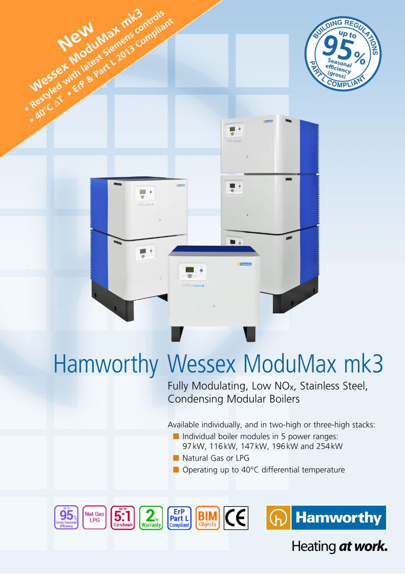
Wessex ModuMax mk3Fully Modulating, Low NOx, Stainless Steel, Condensing Modular Boilers
Available individually, and in two-high or three-high stacks:nn Individual boiler modules in 5 power ranges: 97 kW, 116 kW, 147 kW, 196 kW and 254 kWnn Natural Gas or LPGnn Operating up to 40°C differential temperature
Hamworthy
New
Wessex M
oduMax mk3
• Resty
led with
latest
Siemens contro
ls
• 40°C ΔT •
ErP & Part
L 2013 Complia
ntup to
Seasonale�ciency(gross)
95%
2
The new Wessex ModuMax mk3 40° ΔT
maximises boiler condensing operation
for greater fuel savings.
Wider ΔT means reduced system flow
rates, so smaller pumps and smaller pipe
bore sizes can be used for further savings.
The Wessex ModuMax mk3 is a compact, floor standing, condensing, stainless steel modular boiler range, for use with natural gas or LPG, and operates at up to 107.9% net (97.2 % gross) part load efficiency, and up to ~95% gross seasonal efficiency.
Comprising individual single module boilers, and pre-assembled vertical stacks of boiler modules either two- or three-modules high, the Wessex ModuMax mk3 is available in 15 module combinations offering effectively 13 output power options from 97kW to 762kW.
Each Wessex ModuMax mk3 can operate continuously at up to 40°C differential temperature. The 40°C ∆T variants maximise condensing operation and have been designed in direct response to the increased use of wider delta T design methodologies in commercial buildings and district heating systems.
Wessex ModuMax mk3 boilers feature modern controls and use an LPB (Local Process Bus) communication system. Clip-in modules allow the boiler controls to be integrated with building control systems. Sequencing for up to 16 boilers in a multiple boiler installation can be achieved via the Merley sequence controller option, or by using the integral master/slave cascade control.
Pipe kits are available for two- or three-high module stacks and are factory tested and assembled for ease of installation.
Fully Modulating, Low NOx, Condensing Boilers
Wessex ModuMax mk3 40°C differential temperature
~95% gross seasonal efficiency
Close load matching
Fully compliant with ErP and Part L 2013
Passes through a standard doorway
Space-saving stacked module design
Up to 762kW in less than one square metre footprint
BE
NE
FIT
S
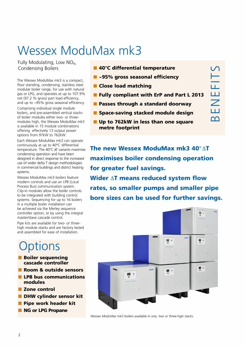
Wessex ModuMax mk3 boilers available in one, two or three-high stacks.
Boiler sequencing cascade controller
Room & outside sensors LPB bus communications modules
Zone control DHW cylinder sensor kit Pipe work header kit NG or LPG Propane
Options
3
Specification
Wessex ModuMax mk3
Hamworthy's philosophy of continuous improvement has resulted in the popular Wessex ModuMax range being further refined to produce the new Wessex ModuMax mk3 condensing boilers.
These compact models offer even higher levels of efficiency than the previous condensing Wessex ModuMax boilers—now with gross seasonal efficiency of around 95%, well in excess of requirements for Part L 2013 and ErP 2015 compliance—ensuring excellent fuel economy and reduced whole-life operating costs.
In response to requests from designers and specifiers for boilers with wider delta T (differential temperature) capability, the Wessex ModuMax mk3 now has extended differential temperature range capability, with each model able to operate up to 40°C differential temperature.
The individual boiler modules are available in 5 output power sizes: 97 kW, 116 kW, 147 kW, 196 kW and 254 kW, and in a choice of 1-, 2-, or 3-modules-high stacks, giving 15 combinations of like-powered modules. Each combination is then available for use with either Natural Gas (NG) or LPG.
Ultra Compact
For the space-conscious designer, large boiler outputs are easily achievable within a minimal environment. The Wessex ModuMax mk3 range packs 762kW into less than one square metre of floor space. This compact design not only reduces the plant room space requirements, but also makes Wessex ModuMax mk3 boilers very easy to install. Each boiler is delivered fully assembled, and even the largest 762 kW model (3-high stack of 254 kW modules) will pass through a standard doorway.
Low Weight
The boilers' lightweight design is about one third of the weight of equivalent traditional cast iron sectional boilers,
Wessex ModuMax mk3 BoilersNatural Gas & LPG
offering the perfect solution for rooftop plant room installation without the need for excessive structural reinforcement.
The Wessex ModuMax mk3 weighs in at less than 1 kg per kW output on the larger models.
Efficient Modulating Operation
The modulating burner operates to 20% of full output for very close load matching to demand. Standing losses are extremely low at less than 1%.
Low Water Content
The low water content enables the Wessex ModuMax mk3 range of boilers to provide rapid response to demand for heat, whilst the modulation responds to closely match the load. This saves energy and reduces the number of firing operations, which saves wear and tear on the boiler.
The Wessex ModuMax mk3 boilers feature a fully modulating pre-mix burner control system. An electronic thermostat monitors the boiler operating conditions and automatically
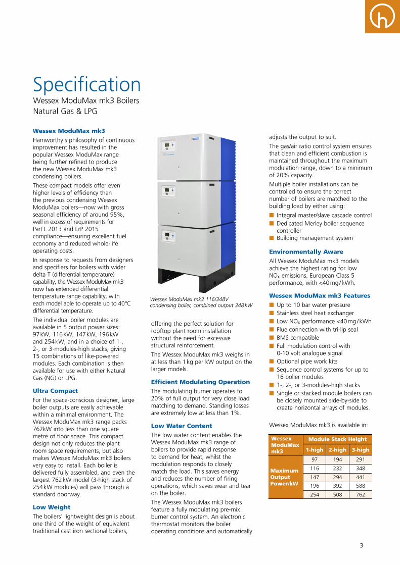
Wessex ModuMax mk3 116/348V condensing boiler, combined output 348 kW
adjusts the output to suit.
The gas/air ratio control system ensures that clean and efficient combustion is maintained throughout the maximum modulation range, down to a minimum of 20% capacity.
Multiple boiler installations can be controlled to ensure the correct number of boilers are matched to the building load by either using:
nn Integral master/slave cascade controlnn Dedicated Merley boiler sequence controller
nn Building management system
Environmentally Aware
All Wessex ModuMax mk3 models achieve the highest rating for low NOx emissions, European Class 5 performance, with <40 mg / kWh.
Wessex ModuMax mk3 Features
nn Up to 10 bar water pressurenn Stainless steel heat exchanger nn Low NOx performance <40 mg / kWhnn Flue connection with tri-lip sealnn BMS compatiblenn Full modulation control with 0-10 volt analogue signal
nn Optional pipe work kitsnn Sequence control systems for up to 16 bolier modules
nn 1-, 2-, or 3-modules-high stacksnn Single or stacked module boilers can be closely mounted side-by-side to create horizontal arrays of modules.
Wessex ModuMax mk3 is available in:
Wessex ModuMax mk3
Module Stack Height
1-high 2-high 3-high
MaximumOutput Power/kW
97 194 291
116 232 348
147 294 441
196 392 588
254 508 762
4
Specification
Construction
The heat exchanger housing in each Wessex ModuMax mk3 boiler module is manufactured from high quality stainless steel for long life, and is fully welded to ensure watertight containment of condensate.
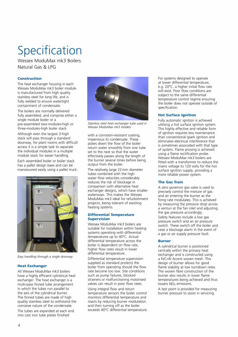
The boilers are normally delivered fully assembled, and comprise either a single module boiler or a pre-assembled two-modules-high or three-modules-high boiler stack.
Although even the largest 3-high stack will pass through a standard doorway, for plant rooms with difficult access it is a simple task to separate the individual modules in a multiple module stack for easier handling.
Each assembled boiler or boiler stack has a pallet design base and can be manoeuvred easily using a pallet truck.
Heat Exchanger
All Wessex ModuMax mk3 boilers have a highly efficient cylindrical heat exchanger. The heat exchanger is a multi-pass finned tube arrangement in which the tubes run parallel to the axis of the cylindrical burner. The finned tubes are made of high quality stainless steel to withstand the corrosive nature of the condensate.
The tubes are expanded at each end into cast iron tube plates finished
Wessex ModuMax mk3 BoilersNatural Gas & LPG
with a corrosion-resistant coating, impervious to condensate. These plates divert the flow of the boiler return water smoothly from one tube set to the next so that the water effectively passes along the length of the burner several times before being output from the boiler.
The relatively large 22 mm diameter tubes combined with the high water flow velocities considerably reduces the risk of blockage in comparison with alternative heat exchanger designs, which have smaller waterways. This makes the Wessex ModuMax mk3 ideal for refurbishment projects, being tolerant of exisiting heating systems.
Differential Temperature SupervisionWessex ModuMax mk3 boilers are suitable for installation within heating systems operating with differential temperatures up to 40°C. Actual differential temperature across the boiler is dependent on flow rate, higher flow rates result in lower differential temperature.
Differential temperature supervision supplied as standard protects the boiler from operating should the flow rate become too low. Site conditions such as pump failures, blocked strainers or malfunctioning motorised valves can result in poor flow rates.
Using integral flow and return temperature sensors the boiler control monitors differential temperature and reacts by reducing burner modulation and then turning off as the boiler exceeds 40°C differential temperature.
For systems designed to operate at lower differential temperature, e.g. 20°C, a higher initial flow rate will exist. Poor flow conditions are subject to the same differential temperature control regime ensuring the boiler does not operate outside of specification.
Hot Surface IgnitionFully automatic ignition is achieved utilising a hot surface ignition system. This highly effective and reliable form of ignition requires less maintenance than conventional spark ignition and eliminates electrical interference that is sometimes associated with that type of system. Flame proving is achieved using a flame rectification probe. Wessex ModuMax mk3 boilers are fitted with a transformer to reduce the mains voltage to 120 volts for the hot surface ignition supply, providing a more reliable power system.
The Gas TrainA zero governor gas valve is used to precisely control the mixture of gas and air entering the burner as the firing rate modulates. This is achieved by measuring the pressure drop across a venturi at the fan inlet and adjusting the gas pressure accordingly.Safety features include a low gas pressure switch and an air pressure switch. These switch off the boiler and raise a blockage alarm in the event of a gas or air supply pressure fault.
BurnerA cylindrical burner is positioned centrally within the primary heat exchanger and is constructed using a FeCrAl Aconit woven mesh. This design of burner allows for good flame stability at low turndown rates. The woven fibre construction of the burner also results in lower flame temperatures being achieved and thus lowers NOx emissions.
A test point is provided for measuring burner pressure to assist in servicing.
Easy handling through a single doorway
Stainless steel heat exchanger tube used in Wessex ModuMax mk3 models
5
Water System
The Wessex ModuMax mk3 is designed for a maximum working pressure of 10 bar. Each module is supplied with a connection for fitting a safety pressure relief valve (not Hamworthy supply).
Where the boiler feed water has a high degree of hardness, it is recommended that the water be treated to prevent precipitation of scale or sludge in the boiler water passageways.
Power Supply
An independent isolator and a fused electrical supply is recommended for each module, to enable each module to be shut down without losing the entire boiler output. 230 volt, 50 Hz single phase.
Remote Signalling
Optional volt free contacts are available to indicate common fault and normal run. The contacts are BMS compatible and allow remote monitoring of boiler operating status.
One volt free contact kit must be specified per boiler module, e.g. for a Wessex ModuMax three high stacked boiler, 3 volt free contact kits should be specified.
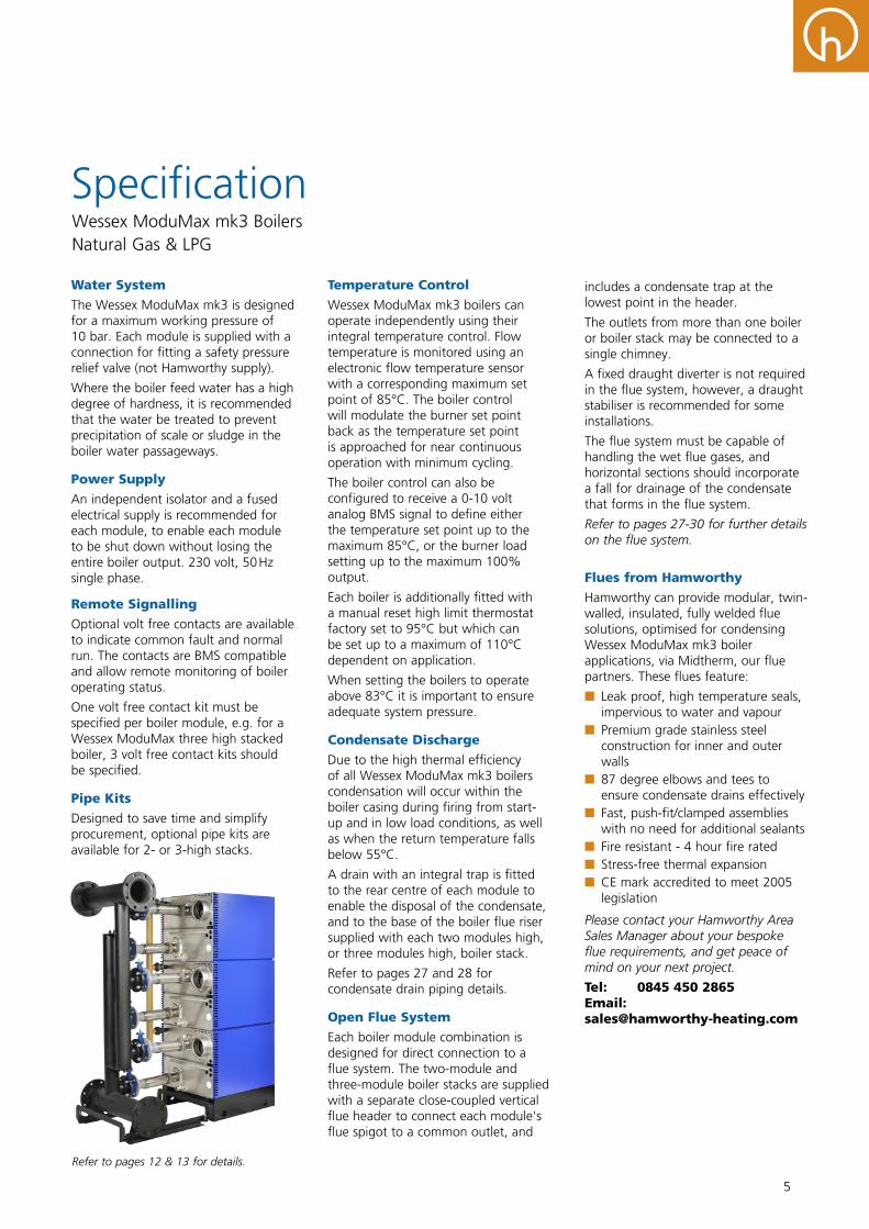
Pipe Kits
Designed to save time and simplify procurement, optional pipe kits are available for 2- or 3-high stacks.
Refer to pages 12 & 13 for details.
Temperature Control
Wessex ModuMax mk3 boilers can operate independently using their integral temperature control. Flow temperature is monitored using an electronic flow temperature sensor with a corresponding maximum set point of 85°C. The boiler control will modulate the burner set point back as the temperature set point is approached for near continuous operation with minimum cycling.
The boiler control can also be configured to receive a 0-10 volt analog BMS signal to define either the temperature set point up to the maximum 85°C, or the burner load setting up to the maximum 100% output.
Each boiler is additionally fitted with a manual reset high limit thermostat factory set to 95°C but which can be set up to a maximum of 110°C dependent on application.
When setting the boilers to operate above 83°C it is important to ensure adequate system pressure.
Condensate Discharge
Due to the high thermal efficiency of all Wessex ModuMax mk3 boilers condensation will occur within the boiler casing during firing from start-up and in low load conditions, as well as when the return temperature falls below 55°C.
A drain with an integral trap is fitted to the rear centre of each module to enable the disposal of the condensate, and to the base of the boiler flue riser supplied with each two modules high, or three modules high, boiler stack.
Refer to pages 27 and 28 for condensate drain piping details.
Open Flue System
Each boiler module combination is designed for direct connection to a flue system. The two-module and three-module boiler stacks are supplied with a separate close-coupled vertical flue header to connect each module's flue spigot to a common outlet, and
includes a condensate trap at the lowest point in the header.
The outlets from more than one boiler or boiler stack may be connected to a single chimney.
A fixed draught diverter is not required in the flue system, however, a draught stabiliser is recommended for some installations.
The flue system must be capable of handling the wet flue gases, and horizontal sections should incorporate a fall for drainage of the condensate that forms in the flue system.
Refer to pages 27-30 for further details on the flue system.
Flues from Hamworthy
Hamworthy can provide modular, twin-walled, insulated, fully welded flue solutions, optimised for condensing Wessex ModuMax mk3 boiler applications, via Midtherm, our flue partners. These flues feature:
nn Leak proof, high temperature seals, impervious to water and vapour
nn Premium grade stainless steel construction for inner and outer walls
nn 87 degree elbows and tees to ensure condensate drains effectively
nn Fast, push-fit/clamped assemblies with no need for additional sealants
nn Fire resistant - 4 hour fire ratednn Stress-free thermal expansion nn CE mark accredited to meet 2005 legislation
Please contact your Hamworthy Area Sales Manager about your bespoke flue requirements, and get peace of mind on your next project.
Tel: 0845 450 2865 Email: [email protected]
SpecificationWessex ModuMax mk3 BoilersNatural Gas & LPG
Wessex ModuMax mk3 Boilers
Multiple Module Boilers
6
Wide choice of outputs & module combinations for close load matching
Small footprint stacks and arrays saves space
Stacked modules offer faster installation
Easier load sharing to reduce wear and tear
ErP 2013/Building Regs. Part L 2013 compliant
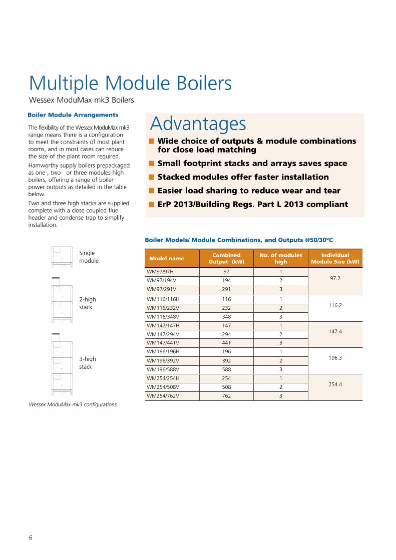
AdvantagesThe flexibility of the Wessex ModuMax mk3 range means there is a configuration to meet the constraints of most plant rooms, and in most cases can reduce the size of the plant room required.
Hamworthy supply boilers prepackaged as one-, two- or three-modules-high boilers, offering a range of boiler power outputs as detailed in the table below.
Two and three high stacks are supplied complete with a close coupled flue header and condense trap to simplify installation.
Wessex ModuMax mk3 configurations.
Model name Combined Output (kW)
No. of moduleshigh
Individual Module Size (kW)
WM97/97H 97 197.2WM97/194V 194 2
WM97/291V 291 3
WM116/116H 116 1116.2WM116/232V 232 2
WM116/348V 348 3
WM147/147H 147 1147.4WM147/294V 294 2
WM147/441V 441 3
WM196/196H 196 1196.3WM196/392V 392 2
WM196/588V 588 3
WM254/254H 254 1254.4WM254/508V 508 2
WM254/762V 762 3
Boiler Module Arrangements
Boiler Models/ Module Combinations, and Outputs @50/30ºC
Singlemodule
2-highstack
3-highstack
7
Multiple Boiler Arrangements
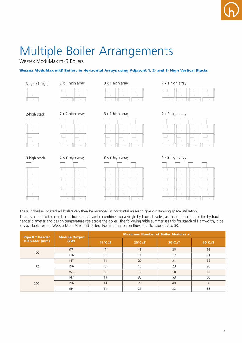
These individual or stacked boilers can then be arranged in horizontal arrays to give outstanding space utilisation.
There is a limit to the number of boilers that can be combined on a single hydraulic header, as this is a function of the hydraulic header diameter and design temperature rise across the boiler. The following table summarises this for standard Hamworthy pipe kits available for the Wessex ModuMax mk3 boiler. For information on flues refer to pages 27 to 30.
Pipe Kit Header Diameter (mm)
Module Output (kW)
Maximum Number of Boiler Modules at
11°C ΔT 20°C ΔT 30°C ΔT 40°C ΔT
10097 7 13 20 26
116 6 11 17 21
150
147 11 20 31 38
196 8 15 23 28
254 6 12 18 22
200
147 19 35 53 66
196 14 26 40 50
254 11 21 32 38
Wessex ModuMax mk3 Boilers in Horizontal Arrays using Adjacent 1, 2- and 3- High Vertical Stacks
Wessex ModuMax mk3 Boilers
Single (1 high) 2 x 1 high array
2 x 2 high array
2 x 3 high array 3 x 3 high array
3 x 2 high array
3 x 1 high array 4 x 1 high array
4 x 2 high array
4 x 3 high array
2-high stack
3-high stack
8
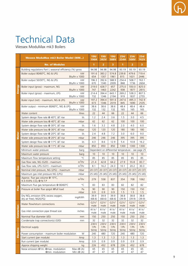
Technical Data
Wessex ModuMax mk3 Boiler Model (WM...) 97/97H
97/194V
97/ 291V
116/ 116H
116/ 232V
116/ 348V
147/ 147H
147/ 294V
147/ 441V
No. of Modules 1 2 3 1 2 3 1 2 3
En
erg
y
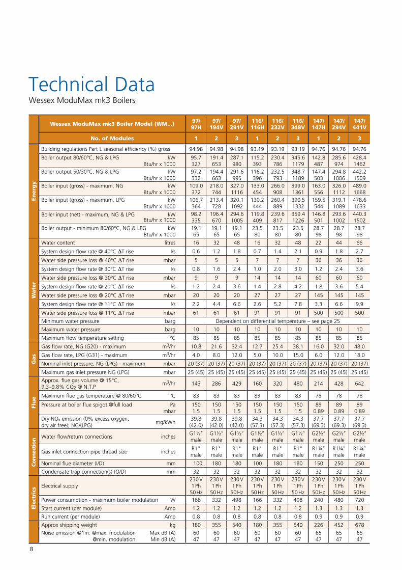
Building regulations Part L seasonal efficiency (%) gross 94.98 94.98 94.98 93.19 93.19 93.19 94.76 94.76 94.76
Boiler output 80/60°C, NG & LPG kW Btu/hr x 1000
95.7327
191.4653
287.1980
115.2393
230.4786
345.61179
142.8487
285.6974
428.41462
Boiler output 50/30°C, NG & LPG kW Btu/hr x 1000
97.2332
194.4663
291.6995
116.2396
232.5793
348.71189
147.4503
294.81006
442.21509
Boiler input (gross) - maximum, NG kW Btu/hr x 1000
109.0372
218.0744
327.01116
133.0454
266.0908
399.01361
163.0556
326.01112
489.01668
Boiler input (gross) - maximum, LPG kW Btu/hr x 1000
106.7364
213.4728
320.11092
130.2444
260.4889
390.51332
159.5544
319.11089
478.61633
Boiler input (net) - maximum, NG & LPG kW Btu/hr x 1000
98.2335
196.4670
294.61005
119.8409
239.6817
359.41226
146.8501
293.61002
440.31502
Boiler output - minimum 80/60°C, NG & LPG kW Btu/hr x 1000
19.165
19.165
19.165
23.580
23.580
23.580
28.798
28.798
28.798
Wate
r
Water content litres 16 32 48 16 32 48 22 44 66
System design flow rate @ 40°C ΔT rise l/s 0.6 1.2 1.8 0.7 1.4 2.1 0.9 1.8 2.7
Water side pressure loss @ 40°C ΔT rise mbar 5 5 5 7 7 7 36 36 36
System design flow rate @ 30°C ΔT rise l/s 0.8 1.6 2.4 1.0 2.0 3.0 1.2 2.4 3.6
Water side pressure loss @ 30°C ΔT rise mbar 9 9 9 14 14 14 60 60 60
System design flow rate @ 20°C ΔT rise l/s 1.2 2.4 3.6 1.4 2.8 4.2 1.8 3.6 5.4
Water side pressure loss @ 20°C ΔT rise mbar 20 20 20 27 27 27 145 145 145
System design flow rate @ 11°C ΔT rise l/s 2.2 4.4 6.6 2.6 5.2 7.8 3.3 6.6 9.9
Water side pressure loss @ 11°C ΔT rise mbar 61 61 61 91 91 91 500 500 500
Minimum water pressure barg Dependent on differential temperature – see page 25
Maximum water pressure barg 10 10 10 10 10 10 10 10 10
Maximum flow temperature setting °C 85 85 85 85 85 85 85 85 85
Gas
Gas flow rate, NG (G20) - maximum m3/hr 10.8 21.6 32.4 12.7 25.4 38.1 16.0 32.0 48.0
Gas flow rate, LPG (G31) - maximum m3/hr 4.0 8.0 12.0 5.0 10.0 15.0 6.0 12.0 18.0
Nominal inlet pressure, NG (LPG) - maximum mbar 20 (37) 20 (37) 20 (37) 20 (37) 20 (37) 20 (37) 20 (37) 20 (37) 20 (37)
Maximum gas inlet pressure NG (LPG) mbar 25 (45) 25 (45) 25 (45) 25 (45) 25 (45) 25 (45) 25 (45) 25 (45) 25 (45)
Flu
e
Approx. flue gas volume @ 15°C, 9.3–9.8% CO2 @ N.T.P
m3/hr 143 286 429 160 320 480 214 428 642
Maximum flue gas temperature @ 80/60°C °C 83 83 83 83 83 83 78 78 78
Pressure at boiler flue spigot @full load Pa mbar
1501.5
1501.5
1501.5
1501.5
1501.5
1501.5
890.89
890.89
890.89
Dry NOx emission (0% excess oxygen, mg/kWh
dry air free); NG/(LPG)
39.8 (42.0)
39.8 (42.0)
39.8 (42.0)
34.3(57.3)
34.3(57.3)
34.3(57.3)
37.7(69.3)
37.7(69.3)
37.7(69.3)
Connec
tion Water flow/return connections inches
G1½ʺ male
G1½ʺ male
G1½ʺ male
G1½ʺ male
G1½ʺ male
G1½ʺ male
G2½ʺ male
G2½ʺ male
G2½ʺ male
Gas inlet connection pipe thread size inches R1" male
R1" male
R1" male
R1" male
R1" male
R1" male
R1¼ʺ male
R1¼ʺ male
R1¼ʺ male
Nominal flue diameter (I/D) mm 100 180 180 100 180 180 150 250 250
Condensate trap connection(s) (O/D) mm 32 32 32 32 32 32 32 32 32
Elec
tric
s Electrical supply230 V 1 Ph
50 Hz
230 V 1 Ph
50 Hz
230 V 1 Ph
50 Hz
230 V 1 Ph
50 Hz
230 V 1 Ph
50 Hz
230 V 1 Ph
50 Hz
230 V 1 Ph
50 Hz
230 V 1 Ph
50 Hz
230 V 1 Ph
50 HzPower consumption - maximum boiler modulation W 166 332 498 166 332 498 240 480 720
Start current (per module) Amp 1.2 1.2 1.2 1.2 1.2 1.2 1.3 1.3 1.3
Run current (per module) Amp 0.8 0.8 0.8 0.8 0.8 0.8 0.9 0.9 0.9
Approx shipping weight kg 180 355 540 180 355 540 226 452 678
Noise emission @1m: @max. modulation Max dB (A) @min. modulation Min dB (A)
6047
6047
6047
6047
6047
6047
6547
6547
6547
Wessex ModuMax mk3 Boilers
9
Technical DataWessex ModuMax mk3 Boilers
Wessex ModuMax mk3 Boiler Model (WM...) 196/196H
196/ 392V
196/ 588V
254/ 254H
254/ 508V
254/ 762V
No. of Modules 1 2 3 1 2 3
En
erg
y
Building regulations Part L seasonal efficiency (%) gross 94.98 94.98 94.98 93.19 93.19 93.19
Boiler output 80/60°C, NG & LPG kW Btu/hr x 1000
191.6654
383.21307
574.81961
239.8815
479.61631
719.42446
Boiler output 50/30°C, NG & LPG kW Btu/hr x 1000
196.3670
392.61340
588.92009
254.4868
508.71736
763.12604
Boiler input (gross) - maximum, NG kW Btu/hr x 1000
219.0747
428.71463
6572242
275.0938
550.01877
825.02815
Boiler input (gross) - maximum, LPG kW Btu/hr x 1000
214.4732
394.41346
643.12194
269.2919
538.31837
807.52755
Boiler input (net) - maximum, NG & LPG kW Btu/hr x 1000
197.2673
394.41346
591.62019
247.6845
495.31690
742.92535
Boiler output - minimum 80/60°C, NG & LPG kW Btu/hr x 1000
38.6132
38.6132
38.6132
48.4165
48.4165
48.4165
Wate
r
Water content litres 22 44 66 22 44 66
System design flow rate @ 40°C ΔT rise l/s 1.2 2.4 3.6 1.5 3.0 4.5
Water side pressure loss @ 40°C ΔT rise mbar 62 62 62 100 100 100
System design flow rate @ 30°C ΔT rise l/s 1.6 3.2 4.8 2.0 4.0 6.0
Water side pressure loss @ 30°C ΔT rise mbar 120 120 120 180 180 180
System design flow rate @ 20°C ΔT rise l/s 2.4 4.8 7.2 3.0 6.0 9.0
Water side pressure loss @ 20°C ΔT rise mbar 246 246 246 395 395 395
System design flow rate @ 11°C ΔT rise l/s 4.3 8.6 12.9 5.4 10.8 16.2
Water side pressure loss @ 11°C ΔT rise mbar 850 850 850 1300 1300 1300
Minimum water pressure barg Dependent on differential temperature – see page 25
Maximum water pressure barg 10 10 10 10 10 10
Maximum flow temperature setting °C 85 85 85 85 85 85
Gas
Gas flow rate, NG (G20) - maximum m3/hr 21.4 42.8 64.2 27.9 55.8 83.7
Gas flow rate, LPG (G31) - maximum m3/hr 8.1 16.2 24.3 10.1 20.2 30.3
Nominal inlet pressure, NG (LPG) - maximum mbar 20 (37) 20 (37) 20 (37) 20 (37) 20 (37) 20 (37)
Maximum gas inlet pressure NG (LPG) mbar 25 (45) 25 (45) 25 (45) 25 (45) 25 (45) 25 (45)
Flu
e
Approx. flue gas volume @ 15°C, 9.3–9.8% CO2 @ N.T.P
m3/hr 279 558 837 354 708 1062
Maximum flue gas temperature @ 80/60°C °C 83 83 83 82 82 82
Pressure at boiler flue spigot @full load Pa mbar
900.9
900.9
900.9
1501.5
1501.5
1501.5
Dry NOx emission (0% excess oxygen, mg/kWh
dry air free); NG/(LPG)
39.9(68.6)
39.9(68.6)
39.9(68.6)
38.8(39.9)
38.8(39.9)
38.8(39.9)
Connec
tion Water flow/return connections inches
G2½ʺ male
G2½ʺ male
G2½ʺ male
G2½ʺ male
G2½ʺ male
G2½ʺ male
Gas inlet connection pipe thread size inches R1¼" male
R1¼" male
R1¼" male
R1¼" male
R1¼" male
R1¼" male
Nominal flue diameter (I/D) mm 150 250 250 150 250 250
Condensate trap connection(s) (O/D) mm 32 32 32 32 32 32
Elec
tric
s Electrical supply230 V 1 Ph
50 Hz
230 V 1 Ph
50 Hz
230 V 1 Ph
50 Hz
230 V 1 Ph
50 Hz
230 V 1 Ph
50 Hz
230 V 1 Ph
50 HzPower consumption - maximum boiler modulation W 240 480 720 240 480 720
Start current (per module) Amp 1.3 1.3 1.3 1.3 1.3 1.3
Run current (per module) Amp 0.9 0.9 0.9 0.9 0.9 0.9
Approx shipping weight kg 226 452 678 226 452 678
Noise emission @1m: @max. modulation Max dB (A) @min. modulation Min dB (A)
6547
6547
6547
6547
6547
6547
10
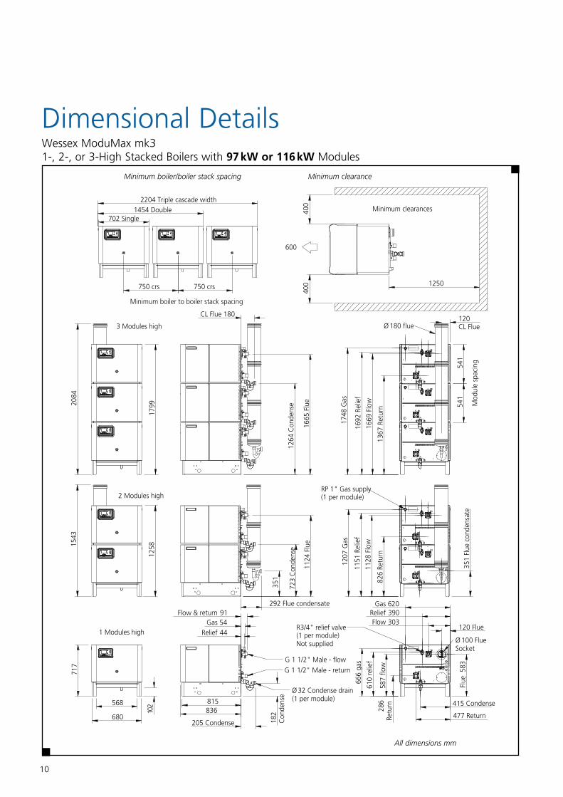
Dimensional DetailsWessex ModuMax mk3 1-, 2-, or 3-High Stacked Boilers with 97 kW or 116 kW Modules
All dimensions mm
Minimum clearanceMinimum boiler/boiler stack spacing
Hamworthy heating ltd 6
Wessex modu Max mk3 Boilers 5000 01308/a
3.0 Size and space requirements
3.1 the we Ssex modu Max Series boiler range has been designed to utilise minimum floor space by stacking boiler
Modules, therefore it is important the pl Antroom has sufficient ceiling height to al Low for installation and connection to the
Flue system.
Also important is allowance for sufficient access at sides and Rear of boiler for flue and pipework connections. See figure
3.1.1 below.
Figure 3.1.1 - dimensions and clearances 97c & 116c
400
400 1250750 crs
390Relief
415 Condense
120 Flue
620Gas
680
568
717
102 815
836
583
Flue
205 Condense
1258
179920
8415
43
54Gas44Relief
292 Flue condensate
351
723
Con
dens
e
Ø 100 Flue Socket
477 Return
303Flow
351
Flue
con
dens
ate
1264
Con
dens
e
587
flow
610
relie
f
666
gas
91Flow & return
G 1 1/2" Male - return
G 1 1/2" Male - flow
Ø 32 Condense drain(1 per module)
286
Retu
rn
182
Con
dens
e
R3/4" relief valve(1 per module)Not supplied
600
RP 1" Gas supply(1 per module)
702 Single1454 Double
2204 Triple cascade width
750 crs
Minimum clearances
3 Modules high
2 Modules high
1 Modules high
Minimum boiler to boiler stack spacing
180CL Flue120CL FlueØ 180 flue
826
Retu
rn
1128
Flo
w
1151
Rel
ief
1207
Gas
1124
Flu
e
Mod
ule
spac
ing
541
541
1367
Ret
urn
1669
Flo
w
1692
Rel
ief
1748
Gas
1665
Flu
e
11
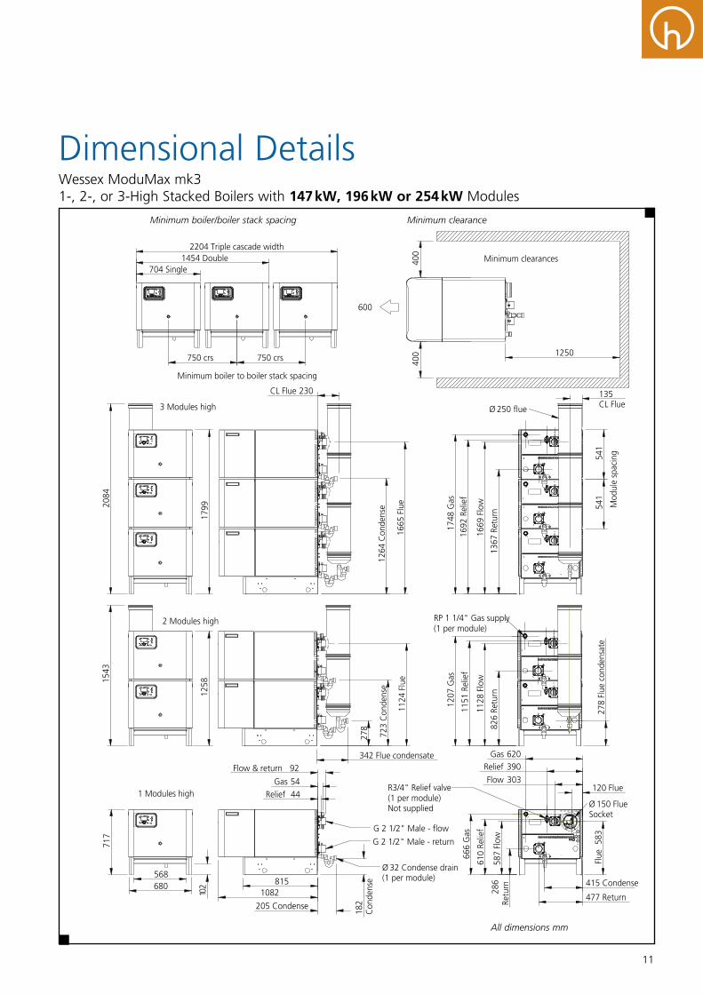
Dimensional DetailsWessex ModuMax mk3 1-, 2-, or 3-High Stacked Boilers with 147 kW, 196 kW or 254 kW Modules
Hamworthy heating ltd 7
Wessex modu Max mk3 Boilers 5000 0130 8/a
Figure 3.1.2 - dimensions and clearances 147/196/254c
400
400 1250750 crs
390Relief
415 Condense
120 Flue
620Gas
680568
717
102 815
1082
583
Flue
205 Condense
1258
179920
8415
43
54Gas44Relief
342 Flue condensate
278
723
Con
dens
e
Ø 150 Flue Socket
477 Return
303Flow
1264
Con
dens
e
587
Flow
610
Relie
f
666
Gas
92Flow & return
G 2 1/2" Male - return
G 2 1/2" Male - flow
Ø 32 Condense drain(1 per module)
286
Retu
rn
182
Con
dens
e
R3/4" Relief valve(1 per module)Not supplied
600
RP 1 1/4" Gas supply(1 per module)
278
Flue
con
dens
ate
750 crs
704 Single1454 Double
2204 Triple cascade widthMinimum clearances
3 Modules high
2 Modules high
1 Modules high
Minimum boiler to boiler stack spacing
230CL Flue 135CL FlueØ 250 flue
Mod
ule
spac
ing
541
541
1207
Gas
1151
Rel
ief
1128
Flo
w
826
Retu
rn
1124
Flu
e16
65 F
lue
1367
Ret
urn
1669
Flo
w
1692
Rel
ief
1748
Gas
Minimum boiler/boiler stack spacing Minimum clearance
All dimensions mm
Dimensional Details
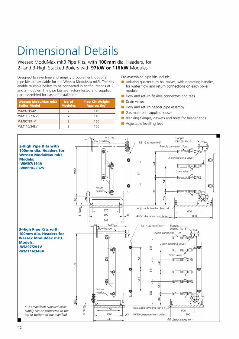
Designed to save time and simplify procurement, optional pipe kits are available for the Wessex ModuMax mk3. The kits enable multiple boilers to be connected in configurations of 2 and 3 modules. The pipe kits are factory tested and supplied part assembled for ease of installation.
Wessex ModuMax mk3 Pipe Kits, with 100 mm dia. Headers, for2- and 3-High Stacked Boilers with 97 kW or 116 kW Modules
12
Wessex ModuMax mk3 Boiler Model
No of Modules
Pipe Kit Weight Approx (kg)
WM97/194V 2 116
WM116/232V 2 116
WM97/291V 3 160
WM116/348V 3 160
2-High Pipe Kits with 100mm dia. Headers for Wessex ModuMax mk3 Models: -WM97/194V -WM116/232V
3-High Pipe Kits with 100mm dia. Headers for Wessex ModuMax mk3 Models: -WM97/291V -WM116/348V
Adjustable levelling feet x 4
DN100, PN16Flanges
R2" Gas manifold*
570
690
747
29
76 747 Typ
180
1052
5N
om.
285
541
586
541
541
800
600
40/50 clearance from boiler
Flow header
Return header
TeeFlexible connector
2-port isolating valve
Drain valve
FlangesDN100, PN16
R2" Gas manifold*
570
690
747
29
180
1593
76 747Typ
541
541
5N
om
.
285
541
541
586
541
541
Adjustable levelling feet x 4
800600
40/50 clearance from boiler
2-port isolating valve
Return header
Flow header
TeeFlexible connector
Drain valve
*Gas manifolds supplied loose. Supply can be connected to the top or bottom of the manifold.
Pre-assembled pipe kits include: n Isolating quarter-turn ball valves, with operating handles, for water flow and return connections on each boiler module
n Flow and return flexible connectors and tees
n Drain valves
n Flow and return header pipe assemby
n Gas manifold (supplied loose)
n Blanking flanges, gaskets and bolts for header ends
n Adjustable levelling feet
All dimensions mm
13
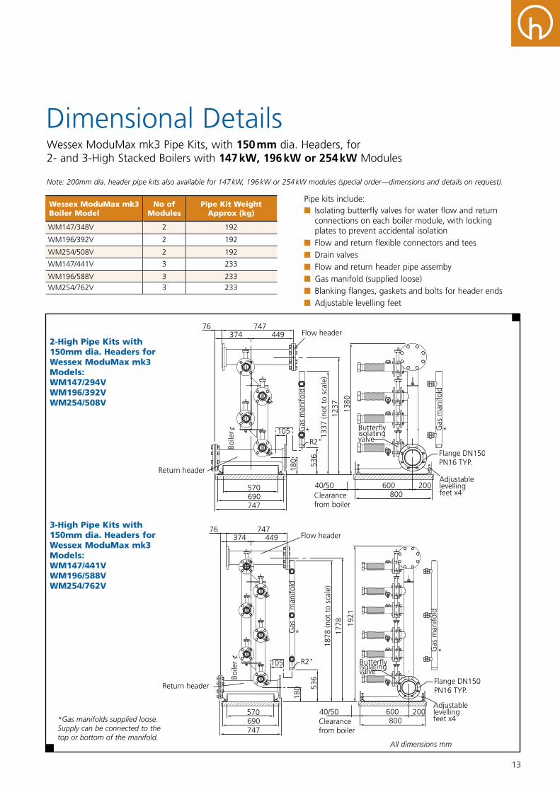
Dimensional DetailsWessex ModuMax mk3 Pipe Kits, with 150 mm dia. Headers, for 2- and 3-High Stacked Boilers with 147 kW, 196 kW or 254 kW Modules
Note: 200mm dia. header pipe kits also available for 147 kW, 196 kW or 254 kW modules (special order—dimensions and details on request).
*Gas manifolds supplied loose. Supply can be connected to the top or bottom of the manifold
Wessex ModuMax mk3 Boiler Model
No of Modules
Pipe Kit Weight Approx (kg)
WM147/348V 2 192
WM196/392V 2 192
WM254/508V 2 192
WM147/441V 3 233
WM196/588V 3 233
WM254/762V 3 233
2-High Pipe Kits with 150mm dia. Headers for Wessex ModuMax mk3 Models: WM147/294V WM196/392V WM254/508V
3-High Pipe Kits with 150mm dia. Headers for Wessex ModuMax mk3 Models: WM147/441V WM196/588V WM254/762V
*Gas manifolds supplied loose. Supply can be connected to the top or bottom of the manifold.
Pipe kits include: n Isolating butterfly valves for water flow and return connections on each boiler module, with locking plates to prevent accidental isolation
n Flow and return flexible connectors and tees n Drain valves n Flow and return header pipe assemby n Gas manifold (supplied loose) n Blanking flanges, gaskets and bolts for header ends n Adjustable levelling feet
All dimensions mm
14
Optional Heating Circuit Control Kit
Up to 3 independent heating circuits incorporating mixing valves is possible with each circuit operating with a different flow and room temperature requirement to the other circuits. The boiler generates flow water to the highest zone temperature requirement whilst the other zones use mixing valve control to reduce flow temperature into their respective circuits. This allows heating to be maintained throughout any demand and domestic hot water requirement.
An optional heating circuit kit must be fitted to the boiler comprising a clip in controls module AGU2.550A109 which the circuit flow temperature sensor, mixing valve and pump are all wired to. Pumps must be connected via a suitably rated contactor – not HHL supply.
There is an optional heating circuit control kit for a single heating circuit, two heating circuits and for three heating circuits.
Part number 563605668 – for single heating circuit.Part number 563605669 – for two heating circuits.Part number 563605670 – for three heating circuits.
Boiler Capacity For Optional Clip In Controls
Each boiler only has the capacity for three optional clip in control kits. If remote fault and run signalling using the optional volt free contact kit is required this will use up one of the optional clip in kit locations. In such instances only 2 optional heating circuit control kits may be fitted.
Optional Room Temperature Sensors
Each heating circuit can be equipped with an independent room temperature sensor. There are two types of room sensor, a fully programmable room sensor QAA75, and an offset adjustable room sensor QAA55. When a room temperature sensor is fitted enhanced control of the heating circuits can be achieved based on both internal and outside air temperatures. This could for instance compensate for an unexpected higher internal air temperature allowing the heating system to start later and at a lower flow temperature saving energy.
Single boilers may be used in a variety of situations, often smaller premises without sophisticated controls such as Building Management Systems. Wessex ModuMax mk3 is perfectly suited to such installations having a control system that’s expandable from very basic integral time clock control with fixed temperature operation all the way up to controlling multiple zone systems with full inside/outside temperature compensation and optimised time programming.
Control functions available as standard (no optional extras):
n Time control with 3 programs per day
n Fixed flow temperature control
n Boiler shunt pump control (pump contactor required to suit electrical load of pump – not HHL supply)
n 5 minute over run for shunt pump
n Pump kick for shunt pump to help prevent seizure
n Frost protection based on water temperature, 5°C fixed set point
Optional Outside Air Temperature Sensor QAC34
Whatever the level of control required it is always recommended to fit an outside air temperature sensor allowing enhanced frost protection for protection of both the building infrastructure and the boiler plant. The sensor should be located on a north facing wall.
Control functions available with outside air temperature sensor fitted:
n 2 Stage frost protection – based on water temperature and outside air temperature
- Stage 1 – Air temperature: starts circulation pumps to move heat around the circuit from within the building protecting the plantroom
- Stage 2 – Water temperature: starts the boiler to prevent water within the system freezing
n Summer shutdown - Stops boiler operation when outside temperature reaches a pre-determined set-point
n Adaptable weather compensation - Matches boiler flow temperature to building thermal dynamics as outside air temperature fluctuates up and down.
Part number 533901457 – Model QAC34
Controls For Single Boilers Wessex ModuMax mk3 Boilers
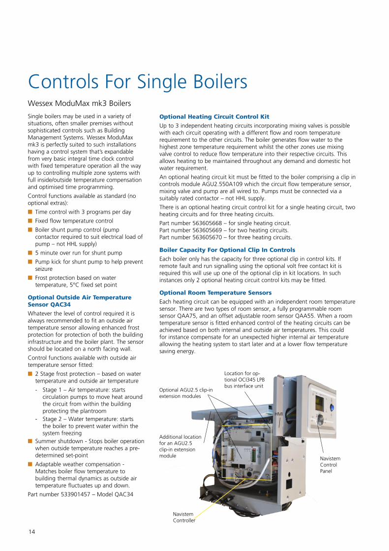
NavistemController
HMI
Optional AGU2.5 clip-in extension modules
Additional location for an AGU2.5 clip-in extension module
Location for op-tional OCI345 LPB bus interface unit
Navistem ControlPanel
15
Optional Programmable Room Sensor - QAA75
The programmable room temperature sensor communicates with the boiler and allows the user full adjustment of the room temperature, time clock, holiday periods and frost protection settings. The unit also displays fault codes from the boiler plant. Alternatively, offset adjustable room sensors are also available, for installations requiring users to have less access to system settings.
n 3 programmable periods per day
n Reduced temperature/night set back for non occupancy hours
n Holiday period (Frost protection remains active)
n Programme lock to prevent tampering
n Indication of operating parameters and boiler fault condition
n 7 day time clock with automatic summer/winter clock adjustment
Part number 533901587 – Model QAA75
Optional Offset Adjustable Room Sensor – QAA55
For installations where limited control is required by the building occupants, the offset adjustable room sensor may be used. This permits adjustment +/- 3°C from the programmed room temperature set point and communicates room temperature to the boiler.
n Setting the operating mode between automatic operation, continuous operation comfort or night setback temperature, off with frost protection active
n Setting a temporary off condition during an un-programmed non occupancy period that will reset automatically according to following program settings
n Programmable lock to prevent tampering.
Part number 533901589 – Model QAA55
Optional Domestic Hot Water Control
A single domestic hot water cylinder (calorifier) may be controlled from the boiler. Energy loading of the cylinder is achieved by starting and stopping the pump to the cylinder coil. Internal temperature sensing for the stored domestic hot water is achieved by either fitting the cylinder with an optional domestic hot water kit (temperature sensor QAZ36 and pocket) or the boiler can be configured to receive a Normally Open/Normally Closed signal from a standard cylinder thermostat. The high limit thermostat for the cylinder must also be wired to ensure the boiler energy supply is isolated from the cylinder in the event of the high limit thermostat setting being reached.
Part number 563605674 – Model QAZ36
Optional Controls Kits For Single Boilers
Controls option Part number
Outside air temperature sensor QAC34 533901457
Domestic Hot Water sensor kit (sensor and pocket) 563605674
Mixing valve heating circuit control kit (clip in control module, temperature sensor and pocket) for 1 zone
563605668
Mixing valve heating circuit control kit (clip in control module, temperature sensor and pocket) for 2 zones
563605669
Mixing valve heating circuit control kit (clip in control module, temperature sensor and pocket) for 3 zones – Note: cannot be used in conjunction with volt free contact kit
563605670
Programmable room sensor QAA75 533901587
Offset adjustable room sensor QAA55 533901589
Remote Start Stop
Each boiler is equipped with a remote start stop circuit. On receiving a start signal from for instance an outside time clock the boiler will operate according to its internal temperature management program. This level of control simply overrides the boilers internal time clock program. The boiler may still be equipped with optional controls including an outside air temperature sensor, room temperature sensors and individual heating zone controls whilst controlling also domestic hot water cylinder using the control options detailed above.
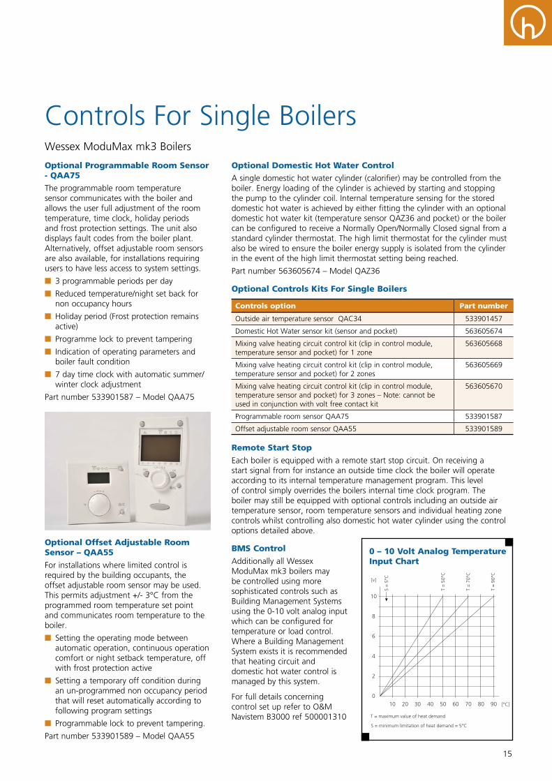
BMS Control
Additionally all Wessex ModuMax mk3 boilers may be controlled using more sophisticated controls such as Building Management Systems using the 0-10 volt analog input which can be configured for temperature or load control. Where a Building Management System exists it is recommended that heating circuit and domestic hot water control is managed by this system.
For full details concerning control set up refer to O&M Navistem B3000 ref 500001310
Controls For Single Boilers Wessex ModuMax mk3 Boilers
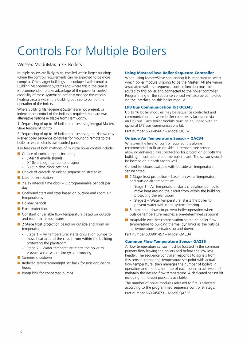
0 – 10 Volt Analog Temperature Input Chart
10
T = maximum value of heat demand S = minimum limitation of heat demand = 5°C
0
2
4
6
8
10
20 30 40 50 60 70 80 90 [°C]
[v]
S =
5°C
T =
50°
C
T =
70°
C
T =
90°
C
10
T = maximum value of heat demand S = minimum limitation of heat demand = 5°C
0
2
4
6
8
10
20 30 40 50 60 70 80 90 [°C]
[v]
S =
5°C
T =
50°
C
T =
70°
C
T =
90°
C
16
Multiple boilers are likely to be installed within larger buildings where the controls requirements can be expected to be more complex. Often larger buildings are equipped with complex Building Management Systems and where this is the case it is recommended to take advantage of the powerful control capability of these systems to not only manage the various heating circuits within the building but also to control the operation of the boilers.
Where Building Management Systems are not present, or independent control of the boilers is required there are two alternative options available from Hamworthy.
1. Sequencing of up to 16 boiler modules using integral Master/Slave feature of control.
2. Sequencing of up to 16 boiler modules using the Hamworthy Merley boiler sequence controller for mounting remote to the boiler or within clients own control panel.
Key features of both methods of multiple boiler control include:
n Choice of control inputs including: - External enable signals - 0-10v analog heat demand signal - Built in time clock settings
n Choice of cascade or unison sequencing strategies
n Lead boiler rotation
n 7 Day integral time clock – 3 programmable periods per day
n Optimised start and stop based on outside and room air temperatures
n Holiday periods
n Frost protection
n Constant or variable flow temperature based on outside and room air temperatures
n 2 Stage frost protection based on outside and room air temperature
- Stage 1 – Air temperature: starts circulation pumps to move heat around the circuit from within the building protecting the plantroom
- Stage 2 – Water temperature: starts the boiler to prevent water within the system freezing
n Summer shutdown
n Reduced temperature/night set back for non occupancy hours
n Pump kick for connected pumps
Using Master/Slave Boiler Sequence Controller When using Master/Slave sequencing it is important to select which boiler module is going to be the Master. All site wiring associated with the sequence control function must be routed to this boiler and connected to the boiler controller. Programming of the sequence control will also be completed via the interface on this boiler module.
LPB Bus Communication Kit OCI345Up to 16 boiler modules may be sequence controlled and communication between boiler modules is facilitated via an LPB bus. Each boiler module must be equipped with an optional LPB bus communications kit.
Part number 563605667 – Model OCI345
Outside Air Temperature Sensor – QAC34Whatever the level of control required it is always recommended to fit an outside air temperature sensor allowing enhanced frost protection for protection of both the building infrastructure and the boiler plant. The sensor should be located on a north facing wall.
Control functions available with outside air temperature sensor fitted:
n 2 Stage frost protection – based on water temperature and outside air temperature
- Stage 1 – Air temperature: starts circulation pumps to move heat around the circuit from within the building protecting the plantroom
- Stage 2 – Water temperature: starts the boiler to prevent water within the system freezing
n Summer shutdown to prevent boiler operation when outside temperature reaches a pre-determined set-point
n Adaptable weather compensation to match boiler flow temperature to building thermal dynamics as the outside air temperature fluctuates up and down.
Part number 533901457 – Model QAC34
Common Flow Temperature Sensor QAZ36A flow temperature sensor must be located in the common primary flow leaving the boilers and before the low loss header. The sequence controller responds to signals from this sensor, comparing temperature set-point with actual flow temperature, then manages the number of boilers in operation and modulation rate of each boiler to achieve and maintain the desired flow temperature. A dedicated sensor kit including immersion pocket is available.
The number of boiler modules released to fire is selected according to the programmed sequence control strategy.
Part number 563605673 – Model QAZ36
Controls For Multiple Boilers Wessex ModuMax mk3 Boilers
17
Controls For Multiple Boilers Wessex ModuMax mk3 Boilers
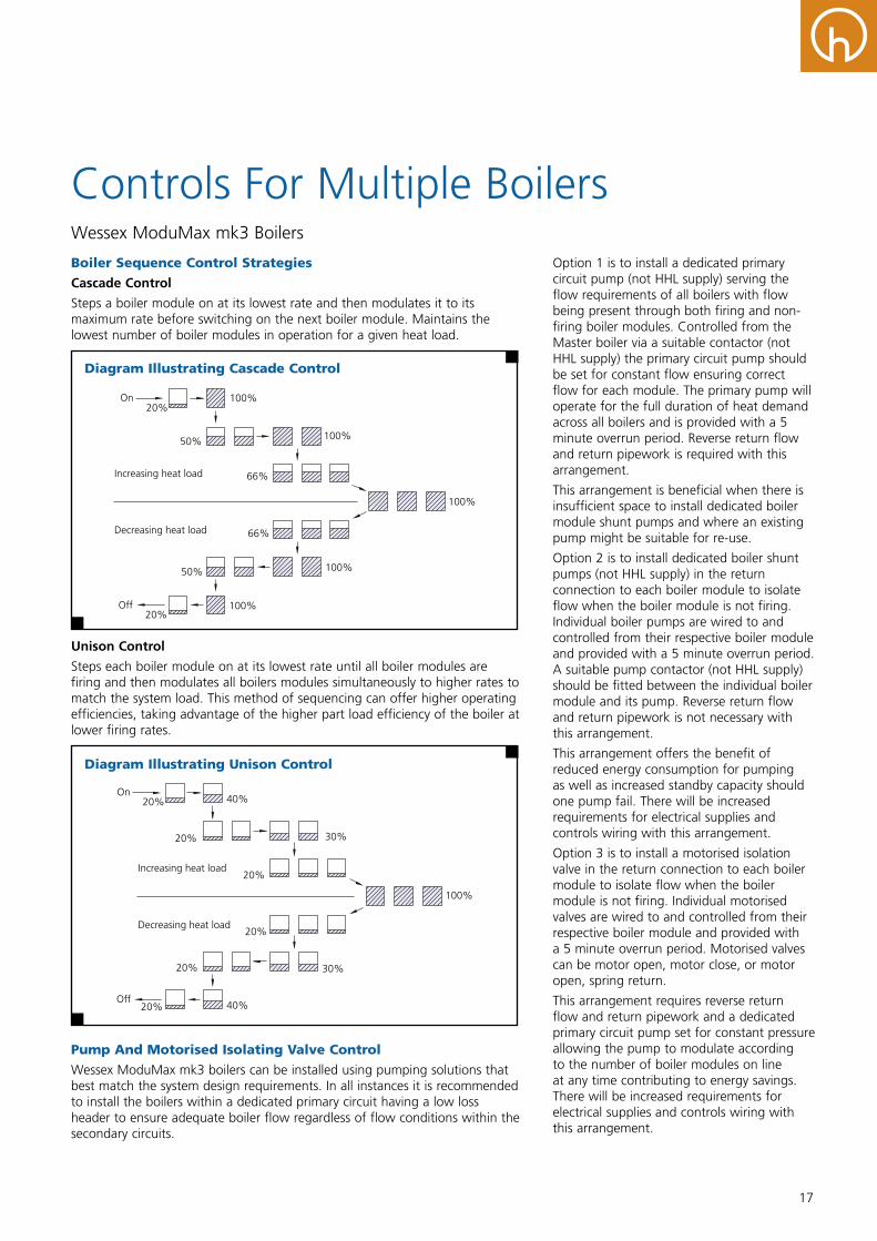
Boiler Sequence Control Strategies
Cascade Control
Steps a boiler module on at its lowest rate and then modulates it to its maximum rate before switching on the next boiler module. Maintains the lowest number of boiler modules in operation for a given heat load.
66%
50%
50%
100%20%
20%
On
Off
100%
100%
100%
100%
66%
Increasing heat load
Decreasing heat load
Diagram Illustrating Cascade Control
Unison Control
Steps each boiler module on at its lowest rate until all boiler modules are firing and then modulates all boilers modules simultaneously to higher rates to match the system load. This method of sequencing can offer higher operating efficiencies, taking advantage of the higher part load efficiency of the boiler at lower firing rates.
Increasing heat load
20%
20%
40%20%
20%
On
Off
30%
100%
20%Decreasing heat load
30%20%
40%
Diagram Illustrating Unison Control
Pump And Motorised Isolating Valve Control
Wessex ModuMax mk3 boilers can be installed using pumping solutions that best match the system design requirements. In all instances it is recommended to install the boilers within a dedicated primary circuit having a low loss header to ensure adequate boiler flow regardless of flow conditions within the secondary circuits.
Option 1 is to install a dedicated primary circuit pump (not HHL supply) serving the flow requirements of all boilers with flow being present through both firing and non-firing boiler modules. Controlled from the Master boiler via a suitable contactor (not HHL supply) the primary circuit pump should be set for constant flow ensuring correct flow for each module. The primary pump will operate for the full duration of heat demand across all boilers and is provided with a 5 minute overrun period. Reverse return flow and return pipework is required with this arrangement.
This arrangement is beneficial when there is insufficient space to install dedicated boiler module shunt pumps and where an existing pump might be suitable for re-use.
Option 2 is to install dedicated boiler shunt pumps (not HHL supply) in the return connection to each boiler module to isolate flow when the boiler module is not firing. Individual boiler pumps are wired to and controlled from their respective boiler module and provided with a 5 minute overrun period. A suitable pump contactor (not HHL supply) should be fitted between the individual boiler module and its pump. Reverse return flow and return pipework is not necessary with this arrangement.
This arrangement offers the benefit of reduced energy consumption for pumping as well as increased standby capacity should one pump fail. There will be increased requirements for electrical supplies and controls wiring with this arrangement.
Option 3 is to install a motorised isolation valve in the return connection to each boiler module to isolate flow when the boiler module is not firing. Individual motorised valves are wired to and controlled from their respective boiler module and provided with a 5 minute overrun period. Motorised valves can be motor open, motor close, or motor open, spring return.
This arrangement requires reverse return flow and return pipework and a dedicated primary circuit pump set for constant pressure allowing the pump to modulate according to the number of boiler modules on line at any time contributing to energy savings. There will be increased requirements for electrical supplies and controls wiring with this arrangement.
18
Time Control
A 7 day time clock with 3 adjustable time periods per day is a standard feature of the sequence controller.
Optimised Start And Stop
The optimiser uses a combination of the actual room temperature and outside air temperature to calculate the exact time at which the heating will be started or stopped to ensure comfort levels at the correct occupancy times.
A self-learning function monitors discrepancies in room temperatures at the pre-defined times allowing the optimiser to fine tune to the building thermal performance.
Manual Over-Ride
Continuous on or off operation can be set during which the time program is over-ridden until the over-ride function is manually de-activated. Frost protection and summer shutdown controls remain active.
Remote Enable
The Master boiler can be programmed to receive an enable signal from an outside control system. Whilst the in-built time clock and optimiser are over-ridden, frost protection and summer shutdown remain active.
Summer Shutdown
Whenever the outside air temperature exceeds the adjustable programmed setting the heating is turned off.
Using BMS 0-10 Volt Signals
The sequence controller can be configured to accept a BMS analog input to initiate heat generation.
NOTE: When using a BMS to initiate cascade control via a 0-10 volt analog signal, the internal time clock and remote enable circuit functions are disabled.
Input signals to the sequence controller must be temperature configured. The input signal is translated to a temperature set point for the flow temperature, and translation is according to a linear graph from 5°C to an upper limit set during commissioning.
10 Volts corresponds with the upper limit with a maximum 85°C setting.
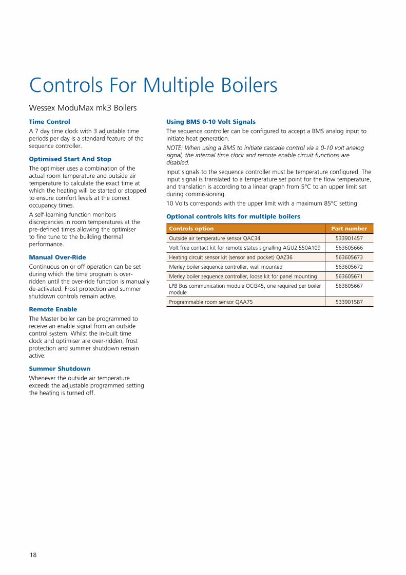
Optional controls kits for multiple boilers
Controls option Part number
Outside air temperature sensor QAC34 533901457
Volt free contact kit for remote status signalling AGU2.550A109 563605666
Heating circuit sensor kit (sensor and pocket) QAZ36 563605673
Merley boiler sequence controller, wall mounted 563605672
Merley boiler sequence controller, loose kit for panel mounting 563605671
LPB Bus communication module OCI345, one required per boiler module
563605667
Programmable room sensor QAA75 533901587
Controls For Multiple Boilers Wessex ModuMax mk3 Boilers
19
High Fireor
O�
150kW Max. plant output 600kWMin. plant output 150kWSeasonal e�ciency ~80%System turndown ratio 4:1
4 x 150kW On/O� Pressure Jet Boilers
High Fireor
Low Fire
150kW Max. plant output 600kWMin. plant output 75kWSeasonal e�ciency ~82%System turndown ratio 8:1
4 x 150kW High/Low Pressure Jet Boilers
147kW
29kW
Max. plant output 588kWMin. plant output 29kWSeasonal e�ciency ~95%System turndown ratio ~20:1
4 x 147kW Fully Modulating Condensing Boilers (Wessex ModuMax mk3)
High Fire toLow Fire
in hundredsof increments
Max. plant output 588kWMin. plant output 39kWSeasonal e�ciency ~95%System turndown ratio ~15:1
3 x 196kW Fully Modulating Condensing Boilers (Wessex ModuMax mk3)
75kW
150kW
75kW
150kW
75kW
150kW
75kW
70kW
o�
70kW
o�
70kW
o�
147kW
29kW
147kW
29kW
147kW
29kW
196kW
39kW
196kW
39kW
196kW
39kW
O�
150kW
O�
150kW
O�
150kW
O�
High Fire toLow Fire
in hundredsof increments
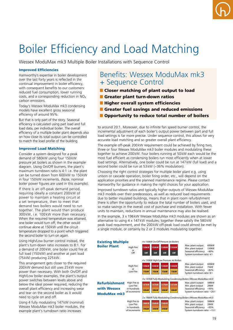
Improved Efficiencies
Hamworthy’s expertise in boiler development over the last forty years is reflected in the continual improvement in boiler efficiency, with consequent benefits to our customers: reduced fuel consumption, lower running costs, and a corresponding reduction in NOx carbon emissions.
Today's Wessex ModuMax mk3 condensing models have excellent gross seasonal efficiency of around 95%.
But that is only part of the story. Seasonal efficiency is calculated using part load and full load data, per individual boiler. The overall efficiency of a multiple boiler plant depends also on how close its total output can be controlled to match the load profile of the building.
Improved Load Matching
Consider a system designed for a peak demand of 580kW using four 150 kW pressure jet boilers as shown in the example diagram. Using On/Off burners, the plant's maximum turndown ratio is 4:1 i.e. the plant can be turned down from 600 kW to 150 kW in four 150 kW increments. (Note, nominal boiler power figures are used in this example).
If there is an off-peak demand period, requiring ideally a constant 200 kW of power to maintain a heating circuit at a set temperature, then to meet that demand two boilers would need to run together. The plant would then produce 300 kW, i.e. 100 kW more than necessary. When the required temperature was attained, one boiler would turn off, the other would continue alone at 150 kW until the circuit temperature dropped to a point which triggered the second boiler to turn on again.
Using High/Low burner control instead, the plant's turn-down ratio increases to 8:1. For a demand of 200 kW, one boiler could fire at full load (150 kW) and another at part load (75 kW) producing 225 kW.
This arrangement gets closer to the required 200 kW demand but still uses 25 kW more power than necessary. With both On/Off and High/Low boiler examples, the plant's output power switches between levels above and below the ideal power required, reducing the overall plant efficiency and increasing wear and tear on the second boiler as it would need to cycle on and off.
Using 4 fully modulating 147 kW (nominal) Wessex ModuMax mk3 boiler modules, the example plant's turndown ratio increases
Boiler Efficiency and Load MatchingWessex ModuMax mk3 Multiple Boiler Installations with Sequence Control
Benefits: Wessex ModuMax mk3 + Sequence Control
Closer matching of plant output to load Greater plant turn-down ratios Higher overall system efficiencies Greater fuel savings and reduced emissions Opportunity to reduce total number of boilers
to around 20:1. Moreover, due to infinite fan speed burner control, the incremental adjustment of each boiler's output power between part and full load settings is far more precise. Under sequence control, this allows for very accurate load matching and so greater overall plant efficiency.
The example off-peak 200 kW requirement could be achieved by firing two, three or four Wessex ModuMax mk3 boiler modules and modulating these together to achieve 200 kW. Four boilers running at 50 kW each would be the most fuel efficient as condensing boilers run most efficiently when at lower load settings. Alternatively, one boiler could be run at 147 kW (full load) and a second boiler could be run at 53 kW (~36% modulation).
Choosing the right control strategies for multiple boiler plant e.g. using unison or cascade operation, boiler firing order, etc., will depend on the application priorities and the planned maintenance regime. Please contact Hamworthy for guidance in making the right choices for your application.
Improved turndown ratios and typically higher outputs of Wessex ModuMax mk3 models over their predecessors, as well as reduced load requirements due to better insulated buildings, means that in plant room refurbishment there is often the opportunity to reduce the total number of boilers used, and so make savings in the overall cost of purchase and installation. With fewer units to maintain, reductions in annual maintenance may also be realised.
In the example, 3 x 196 kW Wessex ModuMax mk3 modules are shown as an alternative to using 4 x 147 kW modules; together these satisfy the 580 kW peak load requirement, and the 200 kW off-peak load could almost be met by a single module, or certainly by 2 or 3 modules modulating together.
Existing Multiple Boiler Plant
Refurbishment
with Wessex
ModuMax mk3
20
Commonflow sensor
Primarypump
DHW primarypump
Boiler1
Boiler2
Boiler3
Low
loss
head
erMixingvalve
Heatingpump
Heating circuitflow sensor
Roomsensor
Immersionheater
At
leas
tm
inim
umw
orki
ngbo
iler
pres
sure
StrainerClenstonair & dirtseparator
Hortondosingpot
Condensate discharge minimum 5 degrees descent to drain
Primary isolationvalve
Powerstockcalorifier
Key: DHW Domestic Hot Water SRV Safety Relief Valve
SRV
Airseparator
Highest point of thecirculating systemabove the boiler
SRVSRV
Note: Secondary DHW circuitsnot shown for clarity
Wessex ModuMax mk3 boiler modules
Stat
ic h
eigh
t re
quire
d to
satis
fy f
orm
er H
SC P
M5
Mainscoldwater
Watermeter
Feed and expansion tank
Wessex ModuMax mk3 Scheme 1: Open vented System with Low Loss Header
Filename: Wessex-ModuMax-mk3-Scheme1-OpenventedwithLLH-A.pdf
04/2015 Rev A
These schematics are available to download at www.hamworthy-heating.com
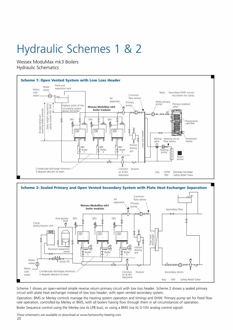
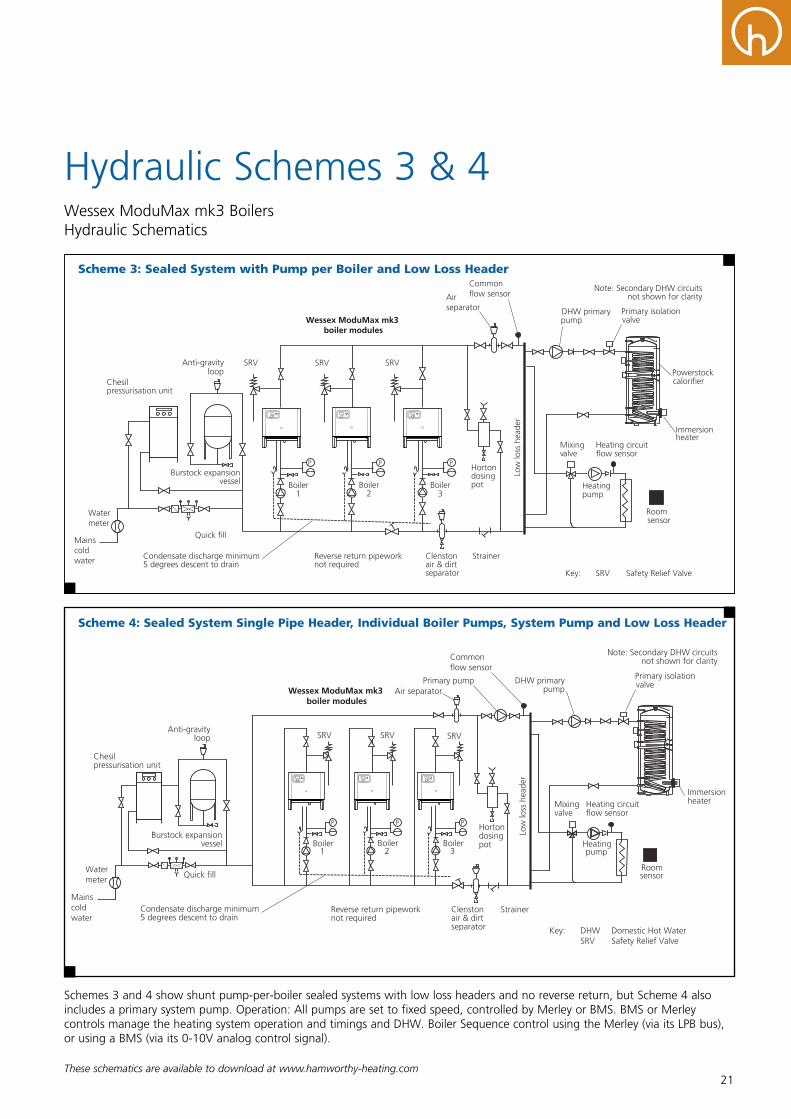
Scheme 1: Open Vented System with Low Loss Header
Hydraulic Schemes 1 & 2 Wessex ModuMax mk3 Boilers Hydraulic Schematics
Boiler1
Boiler2
Boiler3
Plat
ehe
atex
chan
ger
Chesilpressurisation unit
Burstock expansionvessel
Anti-gravityloop
Strainer
Quick fill
Clenston air & dirtseparator
Hortondosingpot
SRV SRV SRV
Secondary return
Secondary flow
P P P
Key: SRV Safety Relief Valve
Wessex ModuMax mk3 boiler modules
Primarypump
Airseparator
Commonflow sensor
Condensate discharge minimum5 degrees descent to drain
Mainscoldwater
Watermeter
Wessex ModuMax mk3 Scheme 3: Sealed Primary and Open Vented Secondary System with Plate Heat Exchanger Separation
Filename: Wessex-ModuMax-mk3-Scheme3-Sealedwithplateandopenvented2nd-A.pdf
04/2015 Rev A
Scheme 2: Sealed Primary and Open Vented Secondary System with Plate Heat Exchanger Separation
Scheme 1 shows an open-vented simple reverse return primary circuit with low loss header. Scheme 2 shows a sealed primary circuit with plate heat exchanger instead of low loss header, with open vented secondary system.
Operation: BMS or Merley controls manage the heating system operation and timings and DHW. Primary pump set for fixed flow rate operation, controlled by Merley or BMS, with all boilers having flow through them in all circumstances of operation.
Boiler Sequence control using the Merley (via its LPB bus), or using a BMS (via its 0-10V analog control signal).
21These schematics are available to download at www.hamworthy-heating.com
Hydraulic Schemes 3 & 4 Wessex ModuMax mk3 Boilers Hydraulic Schematics
Primary pump
Boiler1
Boiler2
Boiler3
Low
loss
head
er
Mixingvalve
Heatingpump
Heating circuitflow sensor
Roomsensor
Immersionheater
Chesil pressurisation unit
Burstock expansion vessel
Anti-gravityloop
Air separator
StrainerReverse return pipeworknot required
SRV
Quick fill
Clenston air & dirtseparator
Hortondosingpot
Condensate discharge minimum5 degrees descent to drain
P P P
SRV SRV
Key: DHW Domestic Hot Water SRV Safety Relief Valve
Wessex ModuMax mk3 boiler modules
Mainscoldwater
Watermeter
DHW primarypump
Primary isolationvalve
Note: Secondary DHW circuitsnot shown for clarityCommon
flow sensor
Wessex ModuMax mk3 Scheme 6: Sealed System Single Pipe Header, Individual Boiler Pumps, System Pump and Low Loss Header
Filename: Wessex-ModuMax-mk3-Singlepipeheaderindivpumps-A.pdf
04/2015 Rev A
Scheme 4: Sealed System Single Pipe Header, Individual Boiler Pumps, System Pump and Low Loss Header
DHW primarypump
Boiler1
Boiler2
Boiler3
Low
loss
head
er
Mixingvalve
Heatingpump
Heating circuitflow sensor
Roomsensor
Immersionheater
Chesilpressurisation unit
Burstock expansionvessel
Anti-gravityloop
Strainer
Quick fill
Clenstonair & dirtseparator
Hortondosingpot
Condensate discharge minimum5 degrees descent to drain
Primary isolationvalve
Powerstockcalorifier
SRV SRV SRV
P P P
Note: Secondary DHW circuitsnot shown for clarity
Reverse return pipework not required
Key: SRV Safety Relief Valve
Wessex ModuMax mk3 boiler modules
Airseparator
Commonflow sensor
Mainscoldwater
Watermeter
Wessex ModuMax mk3 Scheme 5: Sealed System with Pump per Boiler and Low Loss Header
Filename: Wessex-ModuMax-mk3-Scheme5-SealedpumpperboilerLLH-A.pdf
04/2015 Rev A
Scheme 3: Sealed System with Pump per Boiler and Low Loss Header
Schemes 3 and 4 show shunt pump-per-boiler sealed systems with low loss headers and no reverse return, but Scheme 4 also includes a primary system pump. Operation: All pumps are set to fixed speed, controlled by Merley or BMS. BMS or Merley controls manage the heating system operation and timings and DHW. Boiler Sequence control using the Merley (via its LPB bus), or using a BMS (via its 0-10V analog control signal).
22These schematics are available to download at www.hamworthy-heating.com
Boiler1
Boiler2
Boiler3
P P P
Key: DHW Domestic Hot Water SRV Safety Relief Valve
Heatingpump
Roomsensor
Chesilpressurisation unit
Burstock expansionvessel
Anti-gravityloop
Strainer
Quick fill
Clenston air & dirtseparator
Condensate discharge minimum5 degrees descent to drain
Powerstockcalorifier
SRV SRV SRV
Airseparator
Wessex ModuMax mk3 boiler modules
Immersionheater
Mainscoldwater
Watermeter
Commonflow sensor
Primarypump
Mixingvalve
Heating circuitflow sensor
Horton dosingpot
Low
loss
head
er
DHW primarypump Primary isolation
valve
Flow isolation control valve
Commonflow sensor
Primary pump
Boiler1
Boiler2
Low
loss
head
er
Mixingvalve
Heatingpump
Heating circuit flow sensor
Roomsensor
Chesil pressurisation unit
Burstock expansionvessel
Anti-gravityloop
Air separator
StrainerReverse return pipeworknot required
SRV
Mainscoldwater
Quick fill
Clenston air & dirtseparator
Hortondosingpot
Condensate discharge minimum5 degrees descent to drain
P P
SRV
DHW flow
DHW circulationreturn
SRV
OptionalHamworthytop-to-bottomrecirculationkit
Dorchester DR-FC Evodirect-fired water heater
Optional Hamworthyunvented kit*
*Includes T&P relief valve fitted to water heater, expansion relief valve,expansion vessel, non-return valve, pressure reducing valve and strainer.
Mainscoldwater
Expansionvessel
DHW pump
Mainsisolation valve
T&P*
IndependentDHW system
Key: DHW Domestic Hot Water SRV Safety Relief Valve T&P Temperature and Pressure relief valve
Wessex ModuMax mk3 boiler modules
Wessex ModuMax mk3 Scheme 8: Sealed Single Pipe System with Independent Direct-Fired Dorchester DHW System
Filename: Wessex-ModuMax-mk3-Scheme8-SealedsingpipeindepDHW-A.pdf
04/2015 Rev A
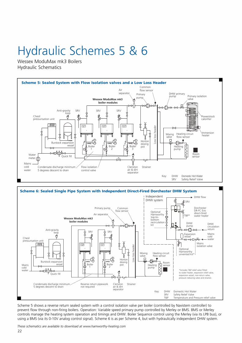
Scheme 5: Sealed System with Flow Isolation valves and a Low Loss Header
Scheme 6: Sealed Single Pipe System with Independent Direct-Fired Dorchester DHW System
Hydraulic Schemes 5 & 6 Wessex ModuMax mk3 Boilers Hydraulic Schematics
Scheme 5 shows a reverse return sealed system with a control isolation valve per boiler (controlled by Navistem controller) to prevent flow through non-firing boilers. Operation: Variable speed primary pump controlled by Merley or BMS. BMS or Merley controls manage the heating system operation and timings and DHW. Boiler Sequence control using the Merley (via its LPB bus), or using a BMS (via its 0-10V analog control signal). Scheme 6 is as per Scheme 4, but with hydraulically independent DHW system.
23
Application & System Data
The installation of the boiler MUST be in accordance with the relevant requirements of the Gas Safety Regulations, Building Regulations, IET Regulations and the Water Supply (Water Fittings) Regulations. It should also be in accordance with any relevant requirements of the local gas region and local authority and the relevant recommendations of the following documents :
These British Standard Codes of Practice and additional publications have relevant recommendations regarding the installation of Wessex ModuMax mk3 boilers.
British Standards
BS EN 806-2 Specification for installations inside buildings conveying water for human consumption – Part 2: Design.
BS EN ISO 4126-1 Safety devices for protection against excessive pressure. Safety valves.
BS 6644 Installation of Gas Fired Hot Water Boilers, 70 kW to 1.8 MW (nett input).
BS 6700 Design, installation, testing and maintenance of services supplying water for domestic use.
BS 6880 Part 1,2 & 3 Code of practice for low temperature hot water heating systems of output greater than 45 kW.
BS 6891 Installation of low pressure gas pipework up to 35 mm (R1¼) in domestic premises.
BS 7074 Application, selection and installation of expansion vessels and ancillary equipment for sealed water systems. Part 2 Code of practice for low and medium temperature hot water systems.
BS 7671 Requirements for electrical installations. IET Wiring Regulations. Seventeenth edition.
BS EN 60335 Part 1 Safety of household and similar electrical appliances – general requirement.
Wessex ModuMax mk3 Boilers
I. Gas E. Publications
IGE/UP/1 Soundness testing and purging of industrial and commercial gas installations.
IGE/UP/1A Soundness testing and direct purging of small low pressure industrial and commercial natural gas installations.
IGE/UP/2 Gas installation pipe work, boosters and compressors in industrial and commercial premises.
IGE/UP/10 Installation of gas appliances in industrial and commercial premises, Part 1 flued appliances.
Health and Safety Executive (HSE)
INDG436 Safe management of industrial steam snd hot water boilers.
BG01 Guidance on Safe Operation of Boilers.
CIBSE Publications
CIBSE Guide B Heating, ventilating, air conditioning and refrigeration.
CIBSE Guide H Building Control Systems.
CIBSE Guide Energy Efficiency in Buildings.
CIBSE Commissioning Code B: 2002.
UK Legislation, UK Public General Acts
Clean Air Act 1993
Location
The location chosen for the boiler must permit the provision of a satisfactory flue system and an adequate air supply. The location must also provide adequate space for servicing and air circulation around each unit. This includes any electrical trunking laid along the floor and to the appliance.
Any combustible material adjacent to the boiler and the flue system must be so placed or shielded to ensure that its temperature does not exceed 65°C. Further details regarding boiler location are given in BS 6644.
Wessex ModuMax mk3 boilers should be positioned on a level non-combustible surface that is capable of supporting the boiler weight when filled with water, plus any ancillary equipment. Adequate space should be allowed for installation and servicing.
Refer to dimensional drawings on pages 10 & 11 for more details.
Adequate Water Flow
The Wessex ModuMax mk3 boiler is designed as a rapid response, low water content unit to run continuously with minimal operating problems. Care should be taken in the initial design and layout, having due regard for adequate water flow through the boilers, and the influence of the control system. Hamworthy strongly recommend that Wessex ModuMax mk3 boilers are installed using the primary circuit design including low loss header to ensure adequate water flow regardless of secondary circuit operating conditions. Refer to technical data tables for minimum water flow requirements.The control system and valves, where fitted, should be regulated to avoid lower flows occurring.All Wessex ModuMax mk3 boilers can operate up to 40°C differential temperature making them suitable for installation in traditional systems operating at 82°C/71°C flow and return temperature up to modern district heating system designs working at 85°C/45°C.
24
Water Systems
Wessex ModuMax mk3 boilers are suitable for both open-vented or sealed pressurised systems. For safe operation (formerly a requirement of the Health and Safety Document PM5; now withdrawn) Hamworthy recommends sealed systems to have a fuel supply cut off in the event of low and high-pressure conditions. Hamworthy also recommend for sealed systems to use a Chesil pressurisation unit with correctly sized Burstock expansion vessels.
It is advisable to thoroughly flush both new as well as existing systems to remove loose debris before connecting the new boilers. For badly contaminated systems it may be necessary to use a proprietary system cleaner to remove stubborn deposits. Once flushing and cleaning is complete suitable corrosion inhibitors should be added to the system and their concentration levels maintained throughout the life of the boiler installation.
The primary circuit should be fitted with a suitable strainer in the common return pipe to the boilers to filter out water born debris. Cleaning strainers should be part of a regular site maintenance schedule.
Additional use of a Clenston dirt and air separator in the primary circuit will help filter out smaller suspended particles as well as micro air bubbles. Reducing air in the system is a major contributor to protection against corrosion, noise and inefficiency.
System Feed Water Quality
If boiler feed water has a high degree of hardness (>180mg CaCO3/litre) it is strongly recommended that the water be treated to prevent the build-up of sludge and scale. Any make up water introduced to the system will dilute water treatment. It is therefore recommended to fit a water meter in the make-up water supply to monitor the volume of water entering the system so that appropriate action can be taken regarding the maintenance of corrosion inhibitor concentration. Metering the make-up water supply will also assist in identifying system leaks which might otherwise go unnoticed, e.g. underground pipe ruptures.
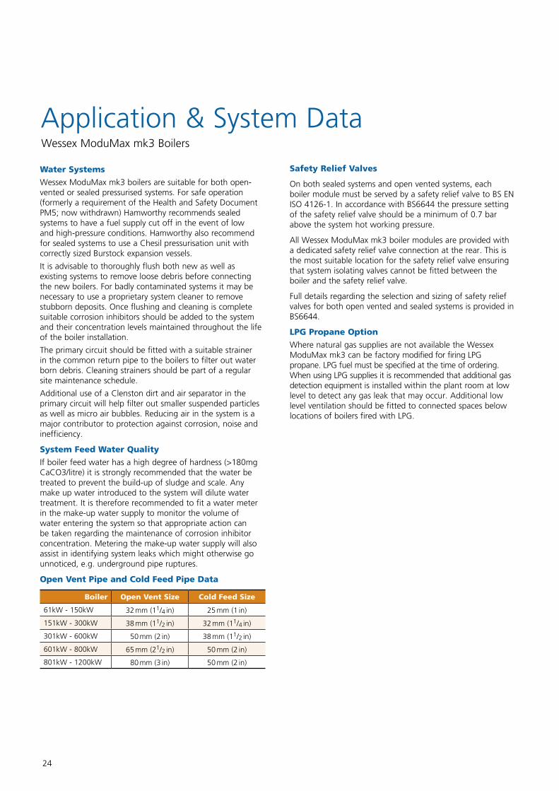
Open Vent Pipe and Cold Feed Pipe Data
Boiler Open Vent Size Cold Feed Size
61kW - 150kW 32 mm (11/4 in) 25 mm (1 in)
151kW - 300kW 38 mm (11/2 in) 32 mm (11/4 in)
301kW - 600kW 50 mm (2 in) 38 mm (11/2 in)
601kW - 800kW 65 mm (21/2 in) 50 mm (2 in)
801kW - 1200kW 80 mm (3 in) 50 mm (2 in)
Safety Relief Valves
On both sealed systems and open vented systems, each boiler module must be served by a safety relief valve to BS EN ISO 4126-1. In accordance with BS6644 the pressure setting of the safety relief valve should be a minimum of 0.7 bar above the system hot working pressure.
All Wessex ModuMax mk3 boiler modules are provided with a dedicated safety relief valve connection at the rear. This is the most suitable location for the safety relief valve ensuring that system isolating valves cannot be fitted between the boiler and the safety relief valve.
Full details regarding the selection and sizing of safety relief valves for both open vented and sealed systems is provided in BS6644.
LPG Propane Option
Where natural gas supplies are not available the Wessex ModuMax mk3 can be factory modified for firing LPG propane. LPG fuel must be specified at the time of ordering. When using LPG supplies it is recommended that additional gas detection equipment is installed within the plant room at low level to detect any gas leak that may occur. Additional low level ventilation should be fitted to connected spaces below locations of boilers fired with LPG.
Application & System DataWessex ModuMax mk3 Boilers
25
Guidance (based on PM5* Health and Safety Executive)
This note states that "hot water boilers should have an automatic control apparatus to cut off fuel to the burners of gas fired plant when the water at or near the boiler flow outlet rises to a predetermined temperature. This should provide a margin of at least 17°C below the temperature of saturated steam corresponding to the pressure at the highest point of the circulation system above the boiler." To comply with this recommendation, the minimum system pressure is dependant on system design flow temperatures and in the case of modular installations, the temperature rise across each module.*Note PM5 has now been withdrawn however Hamworthy still recommend this guidance as sound engineering practice.
Single Installations
The minimum pressure must be equal to the gauge pressure equivalent to the saturated steam temperature obtained by adding 17°C to the required boiler flow temperature. In an open-vented system, the highest point of the circulation system above the boiler should never be less than 2 m (6.5 ft).
Required flow temperature 85°C
Safety margin 17°C
Equivalent saturated steam temperature 102°C
From steam tables the corresponding gauge pressure is 0.1 bar (1.0 m head of water). Note minimum head is 2m.
Modular Installations
The minimum pressure should be equal to the gauge pressure equivalent to the saturated steam temperature. This is obtained by adding 17°C to the sum of the required mixed flow temperature plus the temperature rise across the modules.
System ΔT°C 11°C 20°C 30°C 40°C
Mixed flow temperature 82°C 80°C 85°C 85°C
Safety margin 17°C 17°C 17°C 17°C
Equivalent saturated steam temperature
110°C 117°C 132°C 142°C
Minimum gauge pressure (head of water)
0.43bar 0.80bar 1.88bar 2.81bar
Air Supply and Ventilation
An adequate supply of fresh air for combustion and ventilation must be provided in accordance with BS 6644. The air supply should be achieved using: nn Natural ventilation supplying air with a low level opening and discharge through a smaller sized high level opening.
nn A fan to supply air to low level with natural discharge through a high level opening.
nn A fan to supply air to low level and discharged by means of a fan at a high level.
Note: Fans must be selected such that a negative pressure is not created in the boiler house relative to outside air pressure.
The air supplied for boiler house ventilation should be such that the maximum temperatures within the boiler house are as follows:nn At floor level: 25°C (or 100 mm above the floor level)nn At mid level: 32°C (1.5 m above floor level)nn At ceiling level: 40°C (or 100 mm below ceiling level)
The air supply should be free from contamination such as building dust. To avoid unnecessary cleaning and servicing, we recommend that the boilers are not fired whilst building work is being undertaken.
Where natural ventilation is used suitable permanent openings at low level and high level connected directly to the outside air should be provided. These openings must be fitted with grilles that cannot be blocked or flooded. The free area of the grilles should be as follows:nn At low level (Inlet) 4 cm2 per kW of net heat input.nn At high level (Outlet) 2 cm2 per kW of net heat input.
Where a boiler installation is to operate throughout the summer months, then additional ventilation allowances are required. Refer to BS 6644 for more detailed information.
The Building Regulations 2010 (Revised 2013)
Approved Document L2A 2013 Edition: Conservation of fuel and power (New buildings other than dwellings), Approved Document L2B 2010 Edition: Conservation of fuel and power (Existing buildings, other than dwellings), and Amendments to the Approved Documents, November 2013.These new regulations came into force 6th April 2014. Compliance with the latest regulations now requires a whole buildingapproach to reduction in carbon emissions. The 2013 edition requires the use of heat generating plant as detailed in the supporting 2nd tier guide - Non Domestic Building Services Compliance Guide: 2013 Edition.
Minimum Gross Boiler Seasonal Efficiencies
For natural gas single boiler installations, gross boiler seasonal efficiency* must be no less than 86% for new builds (82% for existing builds). For multiple boiler installations, the combined boilers' gross seasonal efficiency must not be less than 86% for new builds (82% for existing builds), with no individual boiler at less than 82% for new builds or existing builds; however for existing builds only, the installation's effective boiler seasonal efficiency** must be no less than 84%. All Wessex ModuMax mk3 boilers exceed these minimum efficiency requirements; individual boiler figures can be found on pages 8 & 9.
*Gross boiler seasonal efficiency is calculated using a combination of part load and full load gross operating efficiencies. **Effective boiler seasonal efficiency = gross boiler seasonal efficiency plus any applicable heating efficiency percentage credits (up to max. 4%).
Application & System DataWessex ModuMax mk3 Boilers—System Head
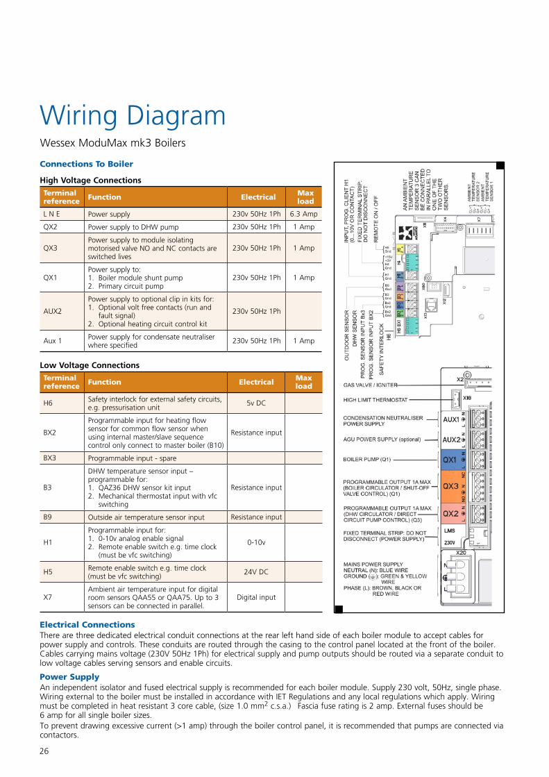
26
Wiring DiagramWessex ModuMax mk3 Boilers
Electrical ConnectionsThere are three dedicated electrical conduit connections at the rear left hand side of each boiler module to accept cables for power supply and controls. These conduits are routed through the casing to the control panel located at the front of the boiler. Cables carrying mains voltage (230V 50Hz 1Ph) for electrical supply and pump outputs should be routed via a separate conduit to low voltage cables serving sensors and enable circuits.
Power SupplyAn independent isolator and fused electrical supply is recommended for each boiler module. Supply 230 volt, 50Hz, single phase. Wiring external to the boiler must be installed in accordance with IET Regulations and any local regulations which apply. Wiring must be completed in heat resistant 3 core cable, (size 1.0 mm2 c.s.a.) Fascia fuse rating is 2 amp. External fuses should be 6 amp for all single boiler sizes.To prevent drawing excessive current (>1 amp) through the boiler control panel, it is recommended that pumps are connected via contactors.
Connections To Boiler
High Voltage Connections
Terminal reference Function Electrical Max
load
L N E Power supply 230v 50Hz 1Ph 6.3 Amp
QX2 Power supply to DHW pump 230v 50Hz 1Ph 1 Amp
QX3Power supply to module isolating motorised valve NO and NC contacts are switched lives
230v 50Hz 1Ph 1 Amp
QX1Power supply to:1. Boiler module shunt pump2. Primary circuit pump
230v 50Hz 1Ph 1 Amp
AUX2
Power supply to optional clip in kits for:1. Optional volt free contacts (run and
fault signal)2. Optional heating circuit control kit
230v 50Hz 1Ph
Aux 1 Power supply for condensate neutraliser where specified
230v 50Hz 1Ph 1 Amp
Low Voltage Connections
Terminal reference Function Electrical Max
load
H6 Safety interlock for external safety circuits, e.g. pressurisation unit
5v DC
BX2
Programmable input for heating flow sensor for common flow sensor when using internal master/slave sequence control only connect to master boiler (B10)
Resistance input
BX3 Programmable input - spare
B3
DHW temperature sensor input – programmable for:1. QAZ36 DHW sensor kit input2. Mechanical thermostat input with vfc
switching
Resistance input
B9 Outside air temperature sensor input Resistance input
H1
Programmable input for:1. 0-10v analog enable signal2. Remote enable switch e.g. time clock
(must be vfc switching)
0-10v
H5 Remote enable switch e.g. time clock (must be vfc switching)
24V DC
X7Ambient air temperature input for digital room sensors QAA55 or QAA75. Up to 3 sensors can be connected in parallel.
Digital input
27
Flue System
Wessex ModuMax mk3 boilers have a pressurised flue outlet, enabling a flue installation to be designed using smaller diameter components.The following points should be noted:
n A suction condition within the flue is not required, so it may be possible to achieve a lower chimney terminal height, however all installations must still comply with the requirements of the Clean Air Act 1956 Memorandum.
n The flue system must be capable of handling saturated flue gases in a positive pressure system.
n The boilers may be flued individually. Details of flue sizes and length of flue runs are shown on page 28.
n The flue components should be fully welded and CE marked for positive pressure application.
nn Draught conditions: the flue must be designed to limit the maximum suction at the flue connection to the boiler to be no greater than 0.3 mbar negative (boilers cold), and with all boilers firing no greater than 1.5 mbar positive. If the flue system generates suction when hot, the maximum suction is 1.0 mbar.
n Where multiple boilers are used, a draught stabiliser located in the end of the header is preferred to individual draught stabilisers located on each boiler outlet. Draught generated: at 80°C, 2 Pa/m at 40°C, 0 Pa/m.
n The flue system must be self supporting and facilitate access for cleaning and maintenance near the boiler connection.
n When designing the flue system, care must be taken to ensure that any condensate that forms within the system can be drained safely to a suitable waste point, and that the flue and drain materials are resistant to the corrosive effect of condensate.
Wessex ModuMax mk3 Boilers
n Wessex ModuMax mk3 boilers are suitable for installation in a balanced compartment in accordance with the requirements of BS 6644.
nn Due to low flue gas temperatures, around 80°C, condensation will occur in the flue therefore flue materials must be impervious to acidic condensate pH 3.5 and use fully sealing joints.
nn Twin-walled flue construction is recommended, with adequate facilities provided for draining the flue condensate.
Flues from Hamworthy
Hamworthy provides modular, twin-walled, insulated, fully welded flue solutions, optimised for Wessex ModuMax mk3 boiler applications, via our flue partners Midtherm. These feature:
n Leak proof, high temperature seals, impervious to water and vapour
n Premium grade stainless steel construction for inner and outer walls
n 87 degree elbows and tees to ensure condensate drains effectively
n Fast, push-fit/clamped assemblies with no need for additional sealants
n Fire resistant - 4 hour fire rated
n Stress-free thermal expansion
n CE mark accredited to meet 2005 legislation
Design & Install or Supply Only
Hamworthy works in partnership with Midtherm Engineering to provide a comprehensive flue design and installation package for all of the Wessex ModuMax mk3 boilers.
Alternatively, flue components can be provided on a supply only basis for the contractor to install.
Please contact your Hamworthy Area Sales Manager about your bespoke flue requirements, and get peace of mind on your next project.
Tel: 0845 450 2865 Email: [email protected]
Boiler and Flue Condensate Discharge
32 mm diameter drain trap connections and drain traps are provided on each Wessex ModuMax mk3 boiler module, and also on the flue risers supplied with two-high and three-high stacked boiler configurations. These are for connection to a condensate drain system (not HH supply) in standard plastic waste piping so that boiler condensate can be safely drained away. The pipework should be a suitable PVC plastic system with sealed joints to prevent the escape of condensate.
The condense drains should be designed in line with BS 6644, incorporating drain traps and an open tundish, with a minimum fall of 2.5 degrees (approximately 50 mm per metre). See "Typical Boiler and Flue Condensate Drain Installation" figure on page 28 for details.Notes
1. Single module Wessex ModuMax mk3 boilers are not supplied with a flue riser and flue riser condense trap, Therefore any flue system used with these boilers should have adequate provision for draining flue condensate.
2. Where multiple Wessex ModuMax mk3 boilers are used with common flue headers feeding a single riser, additional condensate drainage lines may also be required. For more details see pages 29 and 30.
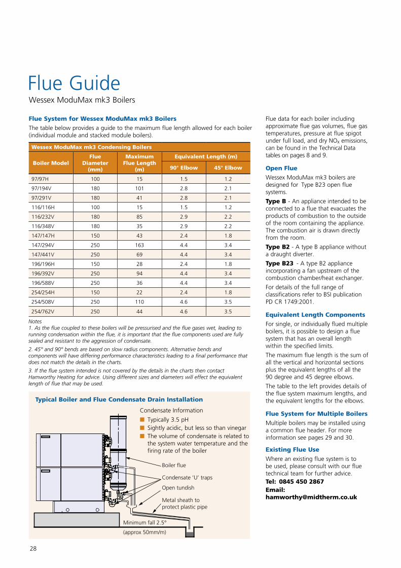
28
Flue GuideWessex ModuMax mk3 Boilers
Flue System for Wessex ModuMax mk3 Boilers
The table below provides a guide to the maximum flue length allowed for each boiler (individual module and stacked module boilers).
Wessex ModuMax mk3 Condensing Boilers
Boiler ModelFlue
Diameter (mm)
Maximum Flue Length
(m)
Equivalent Length (m)
90° Elbow 45° Elbow
97/97H 100 15 1.5 1.2
97/194V 180 101 2.8 2.1
97/291V 180 41 2.8 2.1
116/116H 100 15 1.5 1.2
116/232V 180 85 2.9 2.2
116/348V 180 35 2.9 2.2
147/147H 150 43 2.4 1.8
147/294V 250 163 4.4 3.4
147/441V 250 69 4.4 3.4
196/196H 150 28 2.4 1.8
196/392V 250 94 4.4 3.4
196/588V 250 36 4.4 3.4
254/254H 150 22 2.4 1.8
254/508V 250 110 4.6 3.5
254/762V 250 44 4.6 3.5
Flue data for each boiler including approximate flue gas volumes, flue gas temperatures, pressure at flue spigot under full load, and dry NOx emissions, can be found in the Technical Data tables on pages 8 and 9.
Open Flue
Wessex ModuMax mk3 boilers are designed for Type B23 open flue systems.
Type B - An appliance intended to be connected to a flue that evacuates the products of combustion to the outside of the room containing the appliance. The combustion air is drawn directly from the room.
Type B2 - A type B appliance without a draught diverter.
Type B23 - A type B2 appliance incorporating a fan upstream of the combustion chamber/heat exchanger.
For details of the full range of classifications refer to BSI publication PD CR 1749:2001.
Equivalent Length Components
For single, or individually flued multiple boilers, it is possible to design a flue system that has an overall length within the specified limits.
The maximum flue length is the sum of all the vertical and horizontal sections plus the equivalent lengths of all the 90 degree and 45 degree elbows.
The table to the left provides details of the flue system maximum lengths, and the equivalent lengths for the elbows.
Flue System for Multiple Boilers
Multiple boilers may be installed using a common flue header. For more information see pages 29 and 30.
Existing Flue Use
Where an existing flue system is to be used, please consult with our flue technical team for further advice.Tel: 0845 450 2867 Email: [email protected]
Notes 1. As the flue coupled to these boilers will be pressurised and the flue gases wet, leading to running condensation within the flue, it is important that the flue components used are fully sealed and resistant to the aggression of condensate.
2. 45° and 90° bends are based on slow radius components. Alternative bends and components will have differing performance characteristics leading to a final performance that does not match the details in the charts.
3. If the flue system intended is not covered by the details in the charts then contact Hamworthy Heating for advice. Using different sizes and diameters will effect the equivalent length of flue that may be used.
Typical Boiler and Flue Condensate Drain Installation
Minimum fall 2.5°
(approx 50mm/m)
Open tundish
Metal sheath to protect plastic pipe
Condensate ‘U’ traps
Boiler flue
Condensate Information
nn Typically 3.5 pHnn Sightly acidic, but less so than vinegarnn The volume of condensate is related to the system water temperature and the firing rate of the boiler
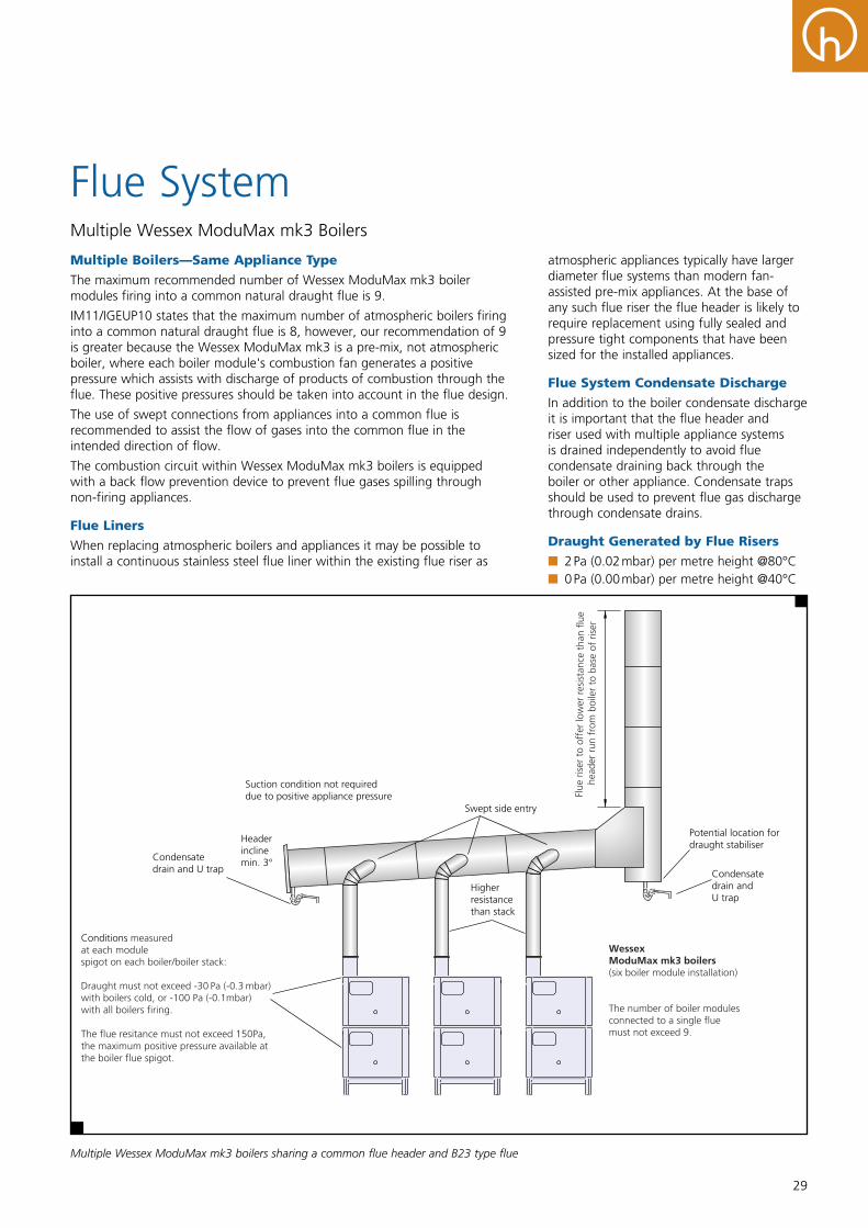
29
Flue SystemMultiple Wessex ModuMax mk3 Boilers
Multiple Boilers—Same Appliance Type
The maximum recommended number of Wessex ModuMax mk3 boiler modules firing into a common natural draught flue is 9.
IM11/IGEUP10 states that the maximum number of atmospheric boilers firing into a common natural draught flue is 8, however, our recommendation of 9 is greater because the Wessex ModuMax mk3 is a pre-mix, not atmospheric boiler, where each boiler module's combustion fan generates a positive pressure which assists with discharge of products of combustion through the flue. These positive pressures should be taken into account in the flue design.
The use of swept connections from appliances into a common flue is recommended to assist the flow of gases into the common flue in the intended direction of flow.
The combustion circuit within Wessex ModuMax mk3 boilers is equipped with a back flow prevention device to prevent flue gases spilling through non-firing appliances.
Flue Liners
When replacing atmospheric boilers and appliances it may be possible to install a continuous stainless steel flue liner within the existing flue riser as
Wessex ModuMax mk3 boilers (six boiler module installation)
The number of boiler modules connected to a single fluemust not exceed 9.
Conditions measured at each modulespigot on each boiler/boiler stack:
Draught must not exceed -30 Pa (-0.3 mbar) with boilers cold, or -100 Pa (-0.1mbar)with all boilers firing. The flue resitance must not exceed 150Pa,the maximum positive pressure available atthe boiler flue spigot.
Suction condition not requireddue to positive appliance pressure
Swept side entry
Potential location fordraught stabiliser
Condensate drain andU trap
Condensate drain and U trap
Header incline min. 3°
Higher resistancethan stack
Flue
ris
er t
o of
fer
low
er r
esis
tanc
e th
an f
lue
head
er r
un f
rom
boi
ler
to b
ase
of r
iser
atmospheric appliances typically have larger diameter flue systems than modern fan-assisted pre-mix appliances. At the base of any such flue riser the flue header is likely to require replacement using fully sealed and pressure tight components that have been sized for the installed appliances.
Flue System Condensate Discharge
In addition to the boiler condensate discharge it is important that the flue header and riser used with multiple appliance systems is drained independently to avoid flue condensate draining back through the boiler or other appliance. Condensate traps should be used to prevent flue gas discharge through condensate drains.
Draught Generated by Flue Risers
nn 2 Pa (0.02 mbar) per metre height @80°Cnn 0 Pa (0.00 mbar) per metre height @40°C
Multiple Wessex ModuMax mk3 boilers sharing a common flue header and B23 type flue
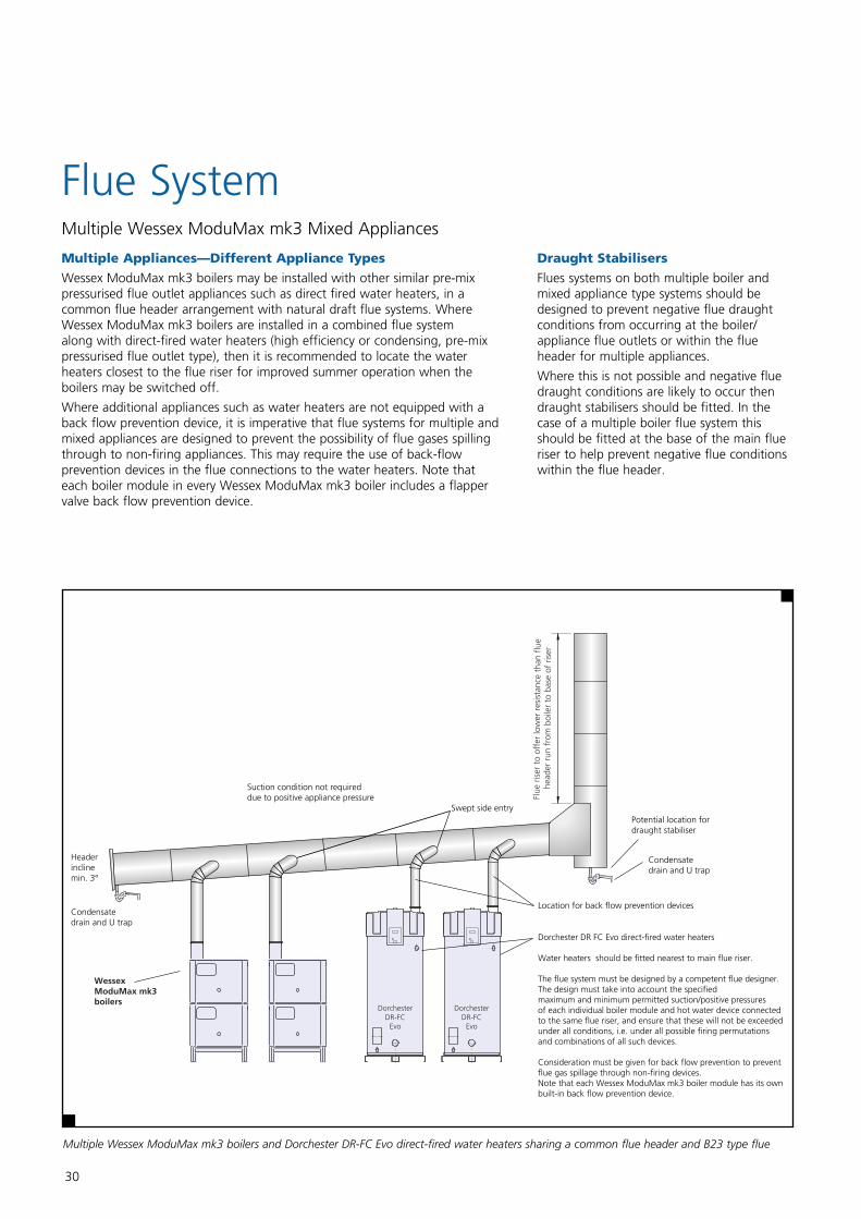
30
Flue SystemMultiple Wessex ModuMax mk3 Mixed Appliances
Multiple Appliances—Different Appliance Types
Wessex ModuMax mk3 boilers may be installed with other similar pre-mix pressurised flue outlet appliances such as direct fired water heaters, in a common flue header arrangement with natural draft flue systems. Where Wessex ModuMax mk3 boilers are installed in a combined flue system along with direct-fired water heaters (high efficiency or condensing, pre-mix pressurised flue outlet type), then it is recommended to locate the water heaters closest to the flue riser for improved summer operation when the boilers may be switched off.
Where additional appliances such as water heaters are not equipped with a back flow prevention device, it is imperative that flue systems for multiple and mixed appliances are designed to prevent the possibility of flue gases spilling through to non-firing appliances. This may require the use of back-flow prevention devices in the flue connections to the water heaters. Note that each boiler module in every Wessex ModuMax mk3 boiler includes a flapper valve back flow prevention device.
WessexModuMax mk3boilers
Dorchester DR FC Evo direct-fired water heaters
Water heaters should be fitted nearest to main flue riser.
The flue system must be designed by a competent flue designer. The design must take into account the specified maximum and minimum permitted suction/positive pressures of each individual boiler module and hot water device connectedto the same flue riser, and ensure that these will not be exceeded under all conditions, i.e. under all possible firing permutations and combinations of all such devices.
Consideration must be given for back flow prevention to prevent flue gas spillage through non-firing devices. Note that each Wessex ModuMax mk3 boiler module has its own built-in back flow prevention device.
Suction condition not requireddue to positive appliance pressure
Swept side entryPotential location fordraught stabiliser
Condensate drain and U trap
Condensatedrain and U trap
Header incline min. 3°
DorchesterDR-FC
Evo
DorchesterDR-FC
Evo
Location for back flow prevention devices
Flue
ris
er t
o of
fer
low
er r
esis
tanc
e th
an f
lue
head
er r
un f
rom
boi
ler
to b
ase
of r
iser
Multiple Wessex ModuMax mk3 boilers and Dorchester DR-FC Evo direct-fired water heaters sharing a common flue header and B23 type flue
Draught Stabilisers
Flues systems on both multiple boiler and mixed appliance type systems should be designed to prevent negative flue draught conditions from occurring at the boiler/appliance flue outlets or within the flue header for multiple appliances.
Where this is not possible and negative flue draught conditions are likely to occur then draught stabilisers should be fitted. In the case of a multiple boiler flue system this should be fitted at the base of the main flue riser to help prevent negative flue conditions within the flue header.
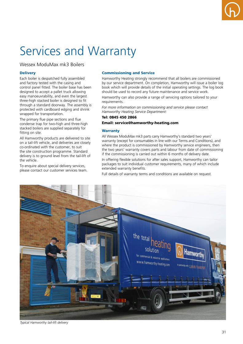
31
Services and WarrantyWessex ModuMax mk3 Boilers
Delivery
Each boiler is despatched fully assembled and factory tested with the casing and control panel fitted. The boiler base has been designed to accept a pallet truck allowing easy manoeuvrability, and even the largest three-high stacked boiler is designed to fit through a standard doorway. The assembly is protected with cardboard edging and shrink wrapped for transportation.
The primary flue pipe sections and flue condense trap for two-high and three-high stacked boilers are supplied separately for fitting on site.
All Hamworthy products are delivered to site on a tail-lift vehicle, and deliveries are closely co-ordinated with the customer, to suit the site construction programme. Standard delivery is to ground level from the tail-lift of the vehicle.
To enquire about special delivery services, please contact our customer services team.
Commissioning and Service
Hamworthy Heating strongly recommend that all boilers are commissioned by our service department. On completion, Hamworthy will issue a boiler log book which will provide details of the initial operating settings. The log book should be used to record any future maintenance and service work.
Hamworthy can also provide a range of servicing options tailored to your requirements.
For more information on commissioning and service please contact Hamworthy Heating Service Department:
Tel: 0845 450 2866
Email: [email protected]
Warranty
All Wessex ModuMax mk3 parts carry Hamworthy's standard two years' warranty (except for consumables in line with our Terms and Conditions), and where the product is commissioned by Hamworthy service engineers, then the two years' warranty covers parts and labour from date of commissioning if the commissioning is carried out within 6 months of delivery date.
In offering flexible solutions for after sales support, Hamworthy can tailor packages to suit individual customer requirements, many of which include extended warranty benefits.
Full details of warranty terms and conditions are available on request.
Typical Hamworthy tail-lift delivery

Customer Service Centre
Hamworthy Heating Limited Fleets Corner, Poole, Dorset BH17 0HH
Telephone: 0845 450 2865 Email: [email protected] Web: www.hamworthy-heating.com
Hamworthy reserves the right to make changes and improvements which may necessitate alteration to the specification without prior notice. 500002659A
Hamworthy Heating Accreditations
ISO 9001 Quality Management System
ISO 14001 Environmental Management System
OHSAS 18001 Health & Safety Management System
The printed version of this brochure is produced using environmentally friendly print solutions
in partnership with our suppliers


![Launchpad Mini [MK3]](https://img.pdfslide.us/doc/110x75/61bd4f1261276e740b117f87/launchpad-mini-mk3.jpg)