Embed Size (px)
Citation preview
Hamrock • Fundamentals of Machine Elements
Chapter 2: Load, Stress and Strain
The careful text-books measure(Let all who build beware!)
The load, the shock, the pressureMaterial can bear.
So when the buckled girderLets down the grinding spanThe blame of loss, or murder
is laid upon the man.Not on the stuff - The Man!
Rudyard Kipling, “Hymn of Breaking Strain”
Hamrock • Fundamentals of Machine Elements
Establishing Critical Section
To establish the critical section and the critical loading, the designer:
1. Considers the external loads applied to a machine (e.g. an automobile).
2. Considers the external loads applied to an element within the machine (e.g. a cylindrical rolling-element bearing.
3. Located the critical section within the machine element (e.g., the inner race).
4. Determines the loading at the critical section (e.g., contact stress).
Hamrock • Fundamentals of Machine Elements
Figure 2.1 A simple crane and forces acting on it. (a) Assembly drawing; (b) free-body diagram of forces acting on the beam.
Example 2.1
Hamrock • Fundamentals of Machine Elements
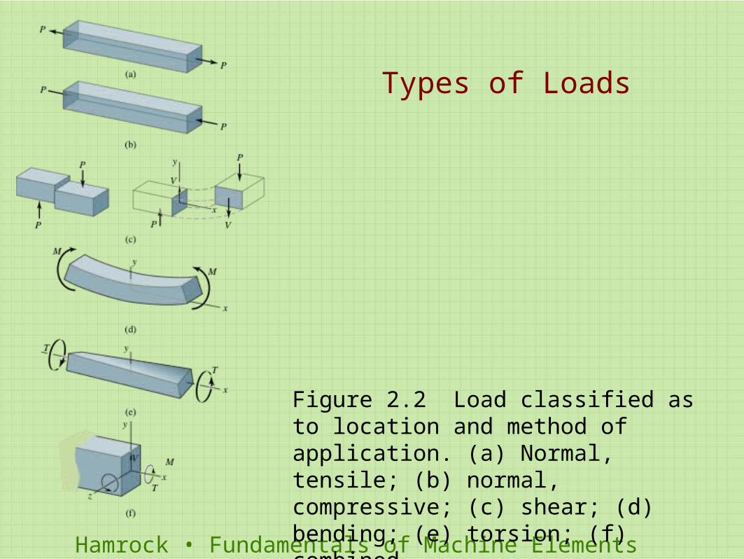
Figure 2.2 Load classified as to location and method of application. (a) Normal, tensile; (b) normal, compressive; (c) shear; (d) bending; (e) torsion; (f) combined.
Types of Loads
Hamrock • Fundamentals of Machine Elements
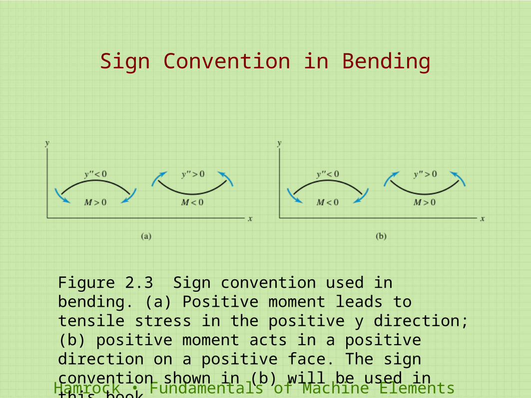
Sign Convention in Bending
Figure 2.3 Sign convention used in bending. (a) Positive moment leads to tensile stress in the positive y direction; (b) positive moment acts in a positive direction on a positive face. The sign convention shown in (b) will be used in this book.
Hamrock • Fundamentals of Machine Elements
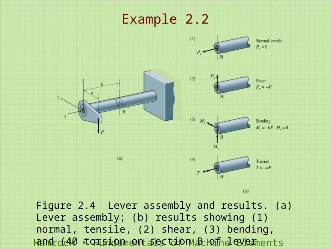
Figure 2.4 Lever assembly and results. (a) Lever assembly; (b) results showing (1) normal, tensile, (2) shear, (3) bending, and (40 torsion on section B of lever assembly.
Example 2.2
Hamrock • Fundamentals of Machine Elements
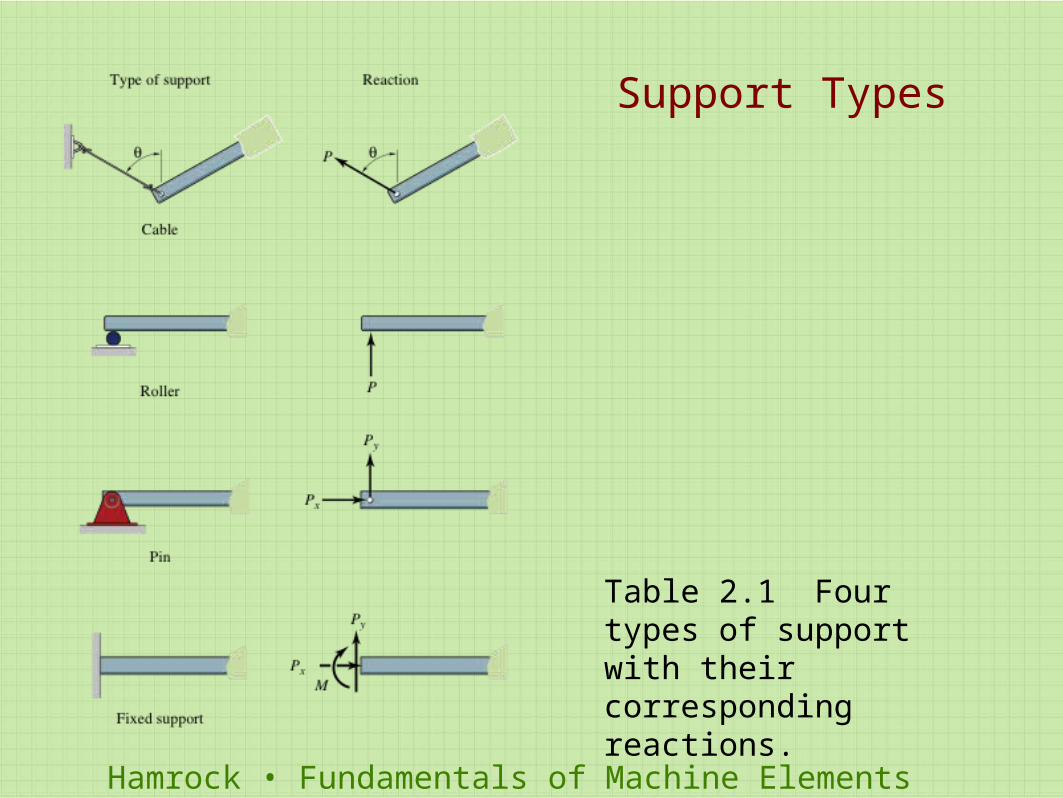
Table 2.1 Four types of support with their corresponding reactions.
Support Types
Hamrock • Fundamentals of Machine Elements
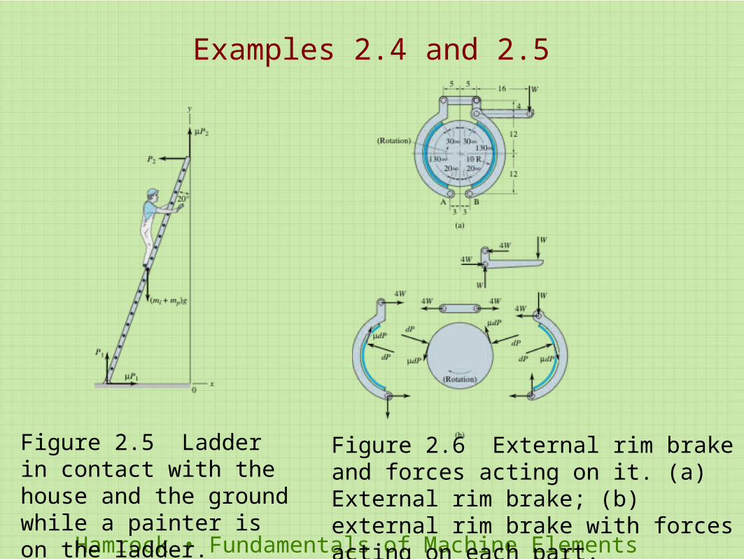
Figure 2.5 Ladder in contact with the house and the ground while a painter is on the ladder.
Figure 2.6 External rim brake and forces acting on it. (a) External rim brake; (b) external rim brake with forces acting on each part.
Examples 2.4 and 2.5
Hamrock • Fundamentals of Machine Elements
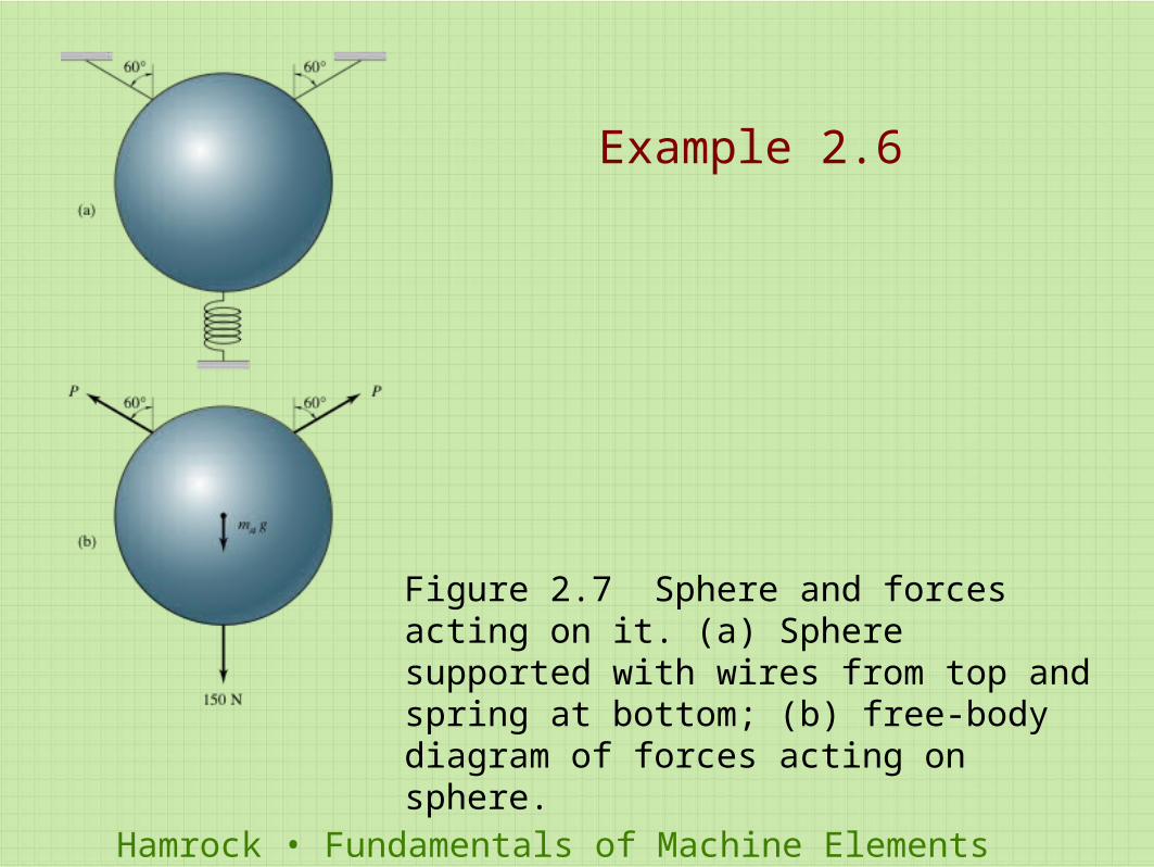
Figure 2.7 Sphere and forces acting on it. (a) Sphere supported with wires from top and spring at bottom; (b) free-body diagram of forces acting on sphere.
Example 2.6
Hamrock • Fundamentals of Machine Elements
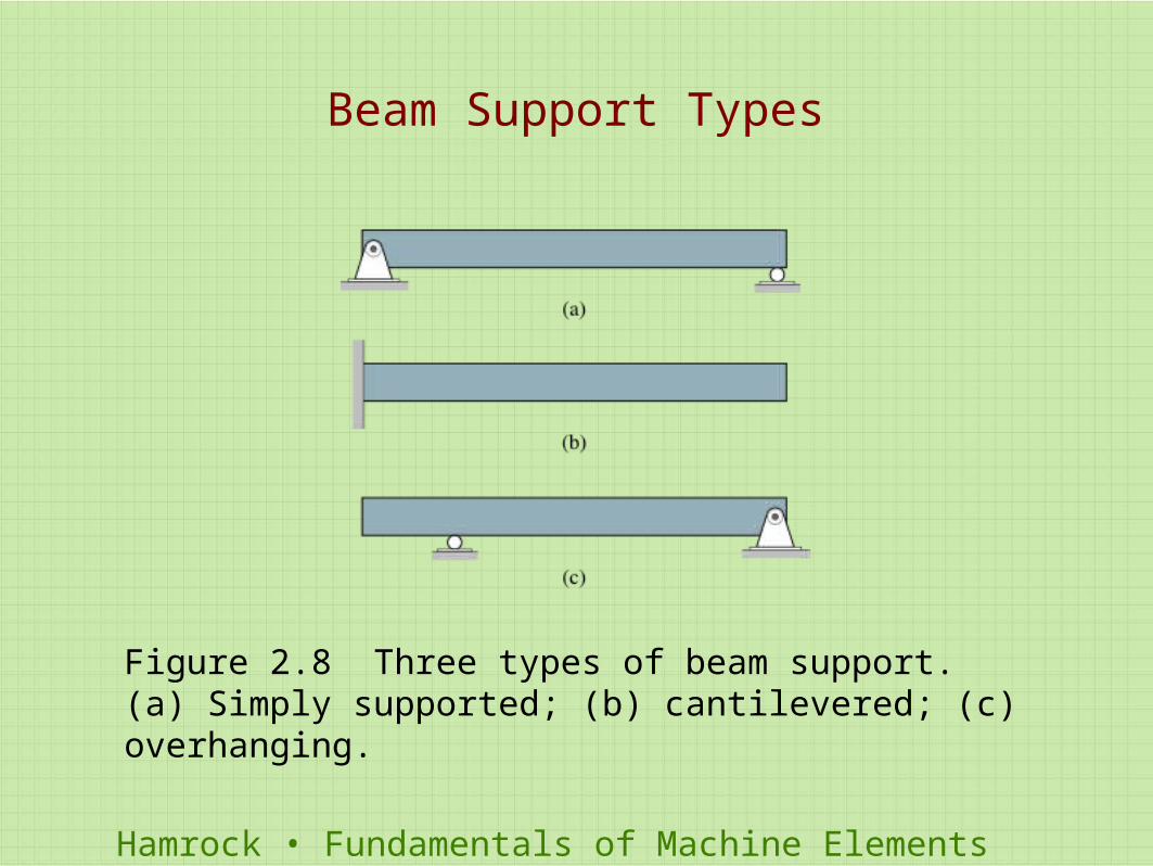
Figure 2.8 Three types of beam support. (a) Simply supported; (b) cantilevered; (c) overhanging.
Beam Support Types
Hamrock • Fundamentals of Machine Elements
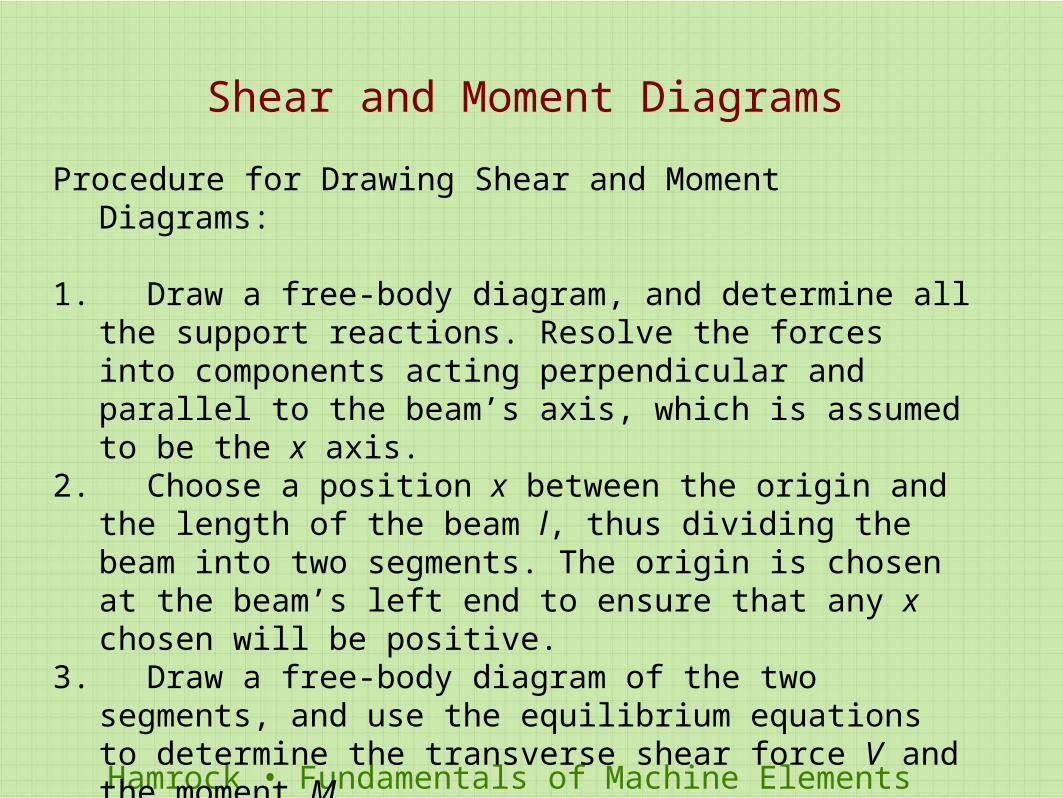
Shear and Moment Diagrams
Procedure for Drawing Shear and Moment Diagrams:
1. Draw a free-body diagram, and determine all the support reactions. Resolve the forces into components acting perpendicular and parallel to the beam’s axis, which is assumed to be the x axis.
2. Choose a position x between the origin and the length of the beam l, thus dividing the beam into two segments. The origin is chosen at the beam’s left end to ensure that any x chosen will be positive.
3. Draw a free-body diagram of the two segments, and use the equilibrium equations to determine the transverse shear force V and the moment M
4. Plot the shear and moment functions versus x. Note the location of the maximum moment. Generally, it is convenient to show the shear and moment diagrams directly below the free-body diagram of the beam.
Hamrock • Fundamentals of Machine Elements
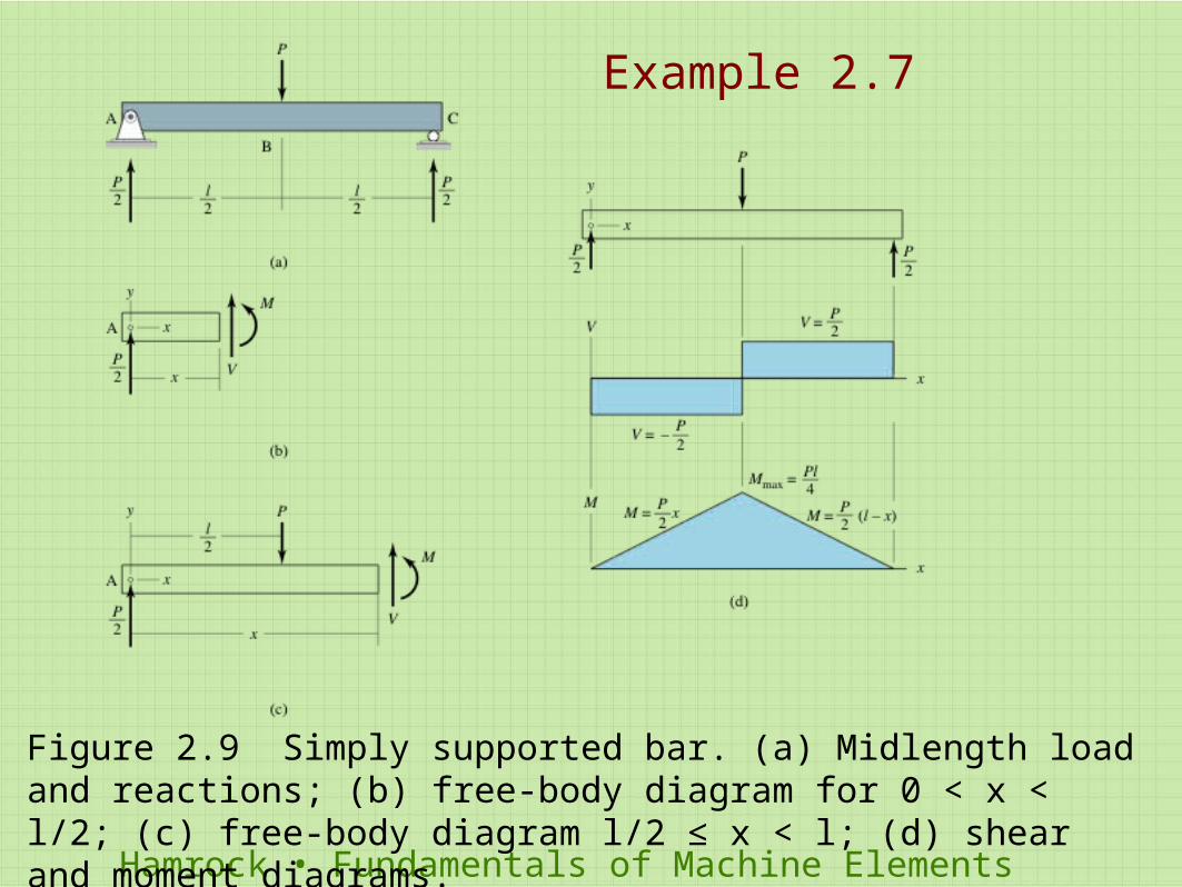
Figure 2.9 Simply supported bar. (a) Midlength load and reactions; (b) free-body diagram for 0 < x < l/2; (c) free-body diagram l/2 ≤ x < l; (d) shear and moment diagrams.
Example 2.7
Hamrock • Fundamentals of Machine Elements
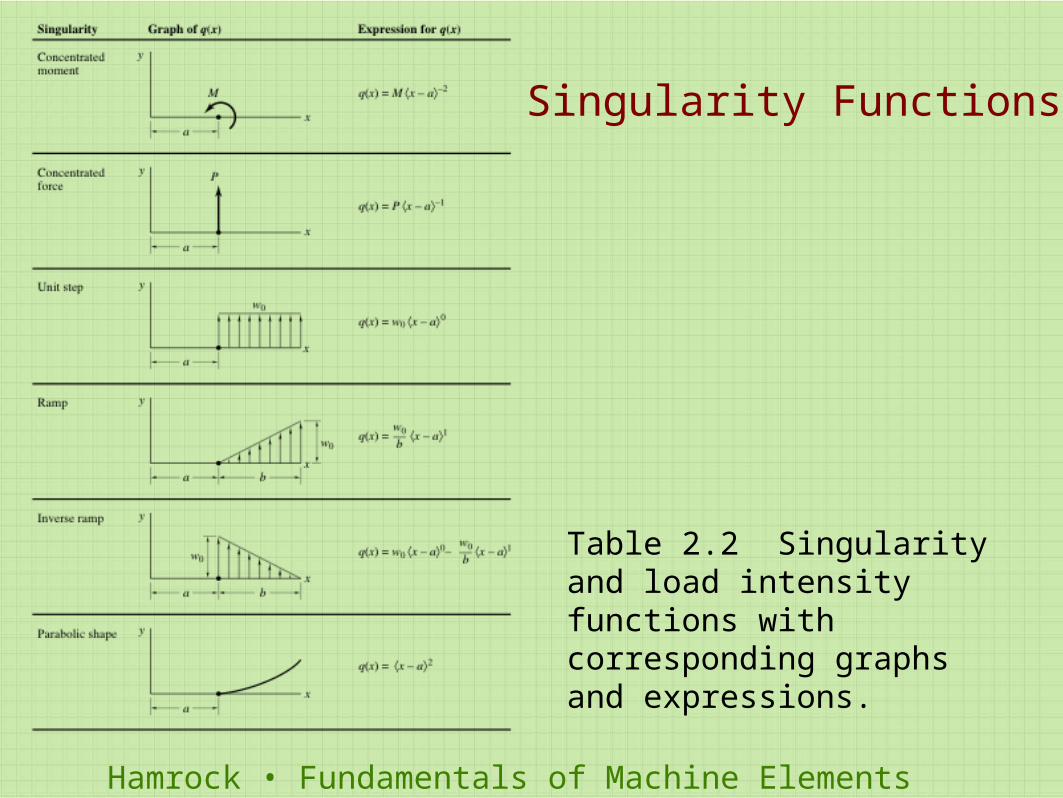
Table 2.2 Singularity and load intensity functions with corresponding graphs and expressions.
Singularity Functions
Hamrock • Fundamentals of Machine Elements
Using Singularity Functions
Procedure for Drawing the Shear and Moment Diagrams by Making Use of Singularity Functions:
1. Draw a free-body diagram with all the singularities acting on the beam, and determine all support reactions. Resolve the forces into components acting perpendicular and parallel to the beam’s axis. 2. Referring to Table 2.2, write an expression for the load intensity function q(x) that describes all the singularities acting on the beam.3. Integrate the negative load intensity function over the beam to get the shear force. Integrate the negative shear force over the beam length to get the moment (see Section 5.2).4. Draw shear and moment diagrams from the expressions developed.
Hamrock • Fundamentals of Machine Elements
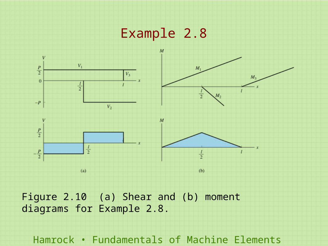
Figure 2.10 (a) Shear and (b) moment diagrams for Example 2.8.
Example 2.8
Hamrock • Fundamentals of Machine Elements
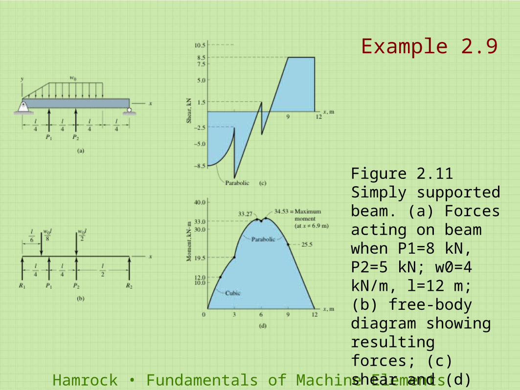
Figure 2.11 Simply supported beam. (a) Forces acting on beam when P1=8 kN, P2=5 kN; w0=4 kN/m, l=12 m; (b) free-body diagram showing resulting forces; (c) shear and (d) moment diagrams for Example 2.9.
Example 2.9
Hamrock • Fundamentals of Machine Elements
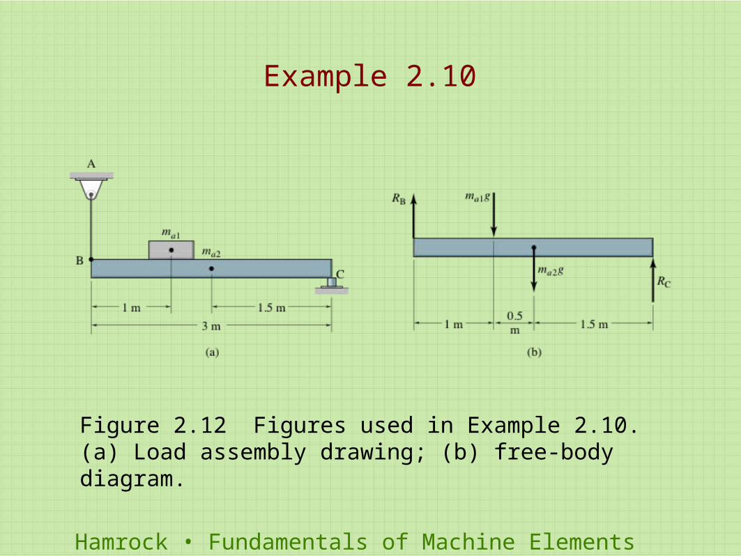
Figure 2.12 Figures used in Example 2.10. (a) Load assembly drawing; (b) free-body diagram.
Example 2.10
Hamrock • Fundamentals of Machine Elements
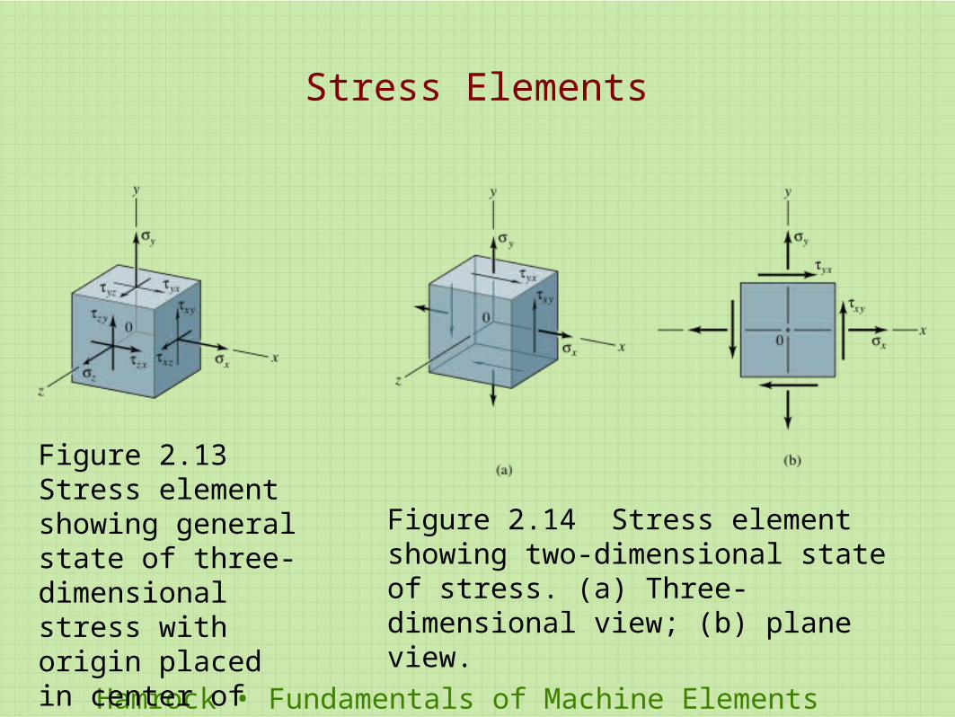
Figure 2.13 Stress element showing general state of three-dimensional stress with origin placed in center of element.
Figure 2.14 Stress element showing two-dimensional state of stress. (a) Three-dimensional view; (b) plane view.
Stress Elements
Hamrock • Fundamentals of Machine Elements
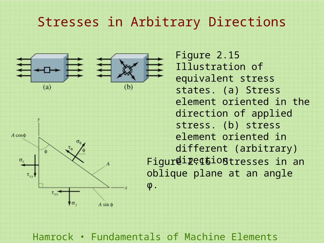
Figure 2.15 Illustration of equivalent stress states. (a) Stress element oriented in the direction of applied stress. (b) stress element oriented in different (arbitrary) direction.
Figure 2.16 Stresses in an oblique plane at an angle φ.
Stresses in Arbitrary Directions
Hamrock • Fundamentals of Machine Elements
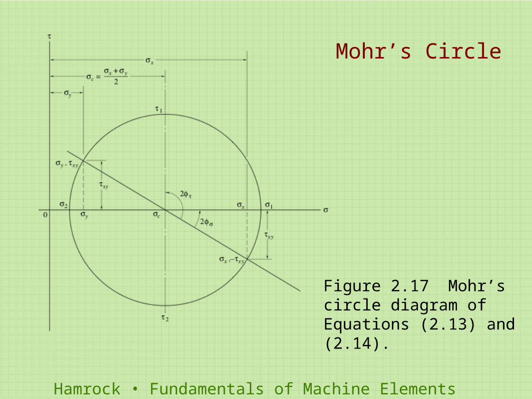
Figure 2.17 Mohr’s circle diagram of Equations (2.13) and (2.14).
Mohr’s Circle
Hamrock • Fundamentals of Machine Elements
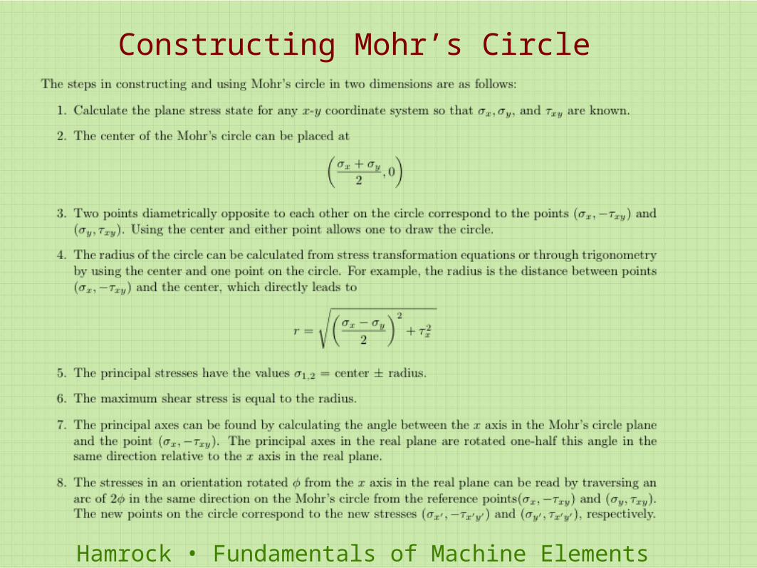
Constructing Mohr’s Circle
Hamrock • Fundamentals of Machine Elements
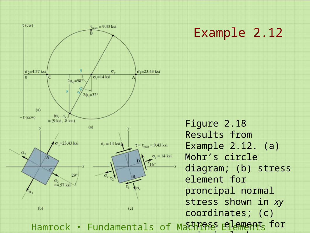
Figure 2.18 Results from Example 2.12. (a) Mohr’s circle diagram; (b) stress element for proncipal normal stress shown in xy coordinates; (c) stress element for principal shear stresses shown in xy coordinates.
Example 2.12
Hamrock • Fundamentals of Machine Elements
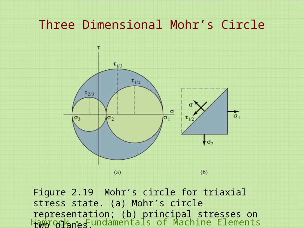
Figure 2.19 Mohr’s circle for triaxial stress state. (a) Mohr’s circle representation; (b) principal stresses on two planes.
Three Dimensional Mohr’s Circle
Hamrock • Fundamentals of Machine Elements
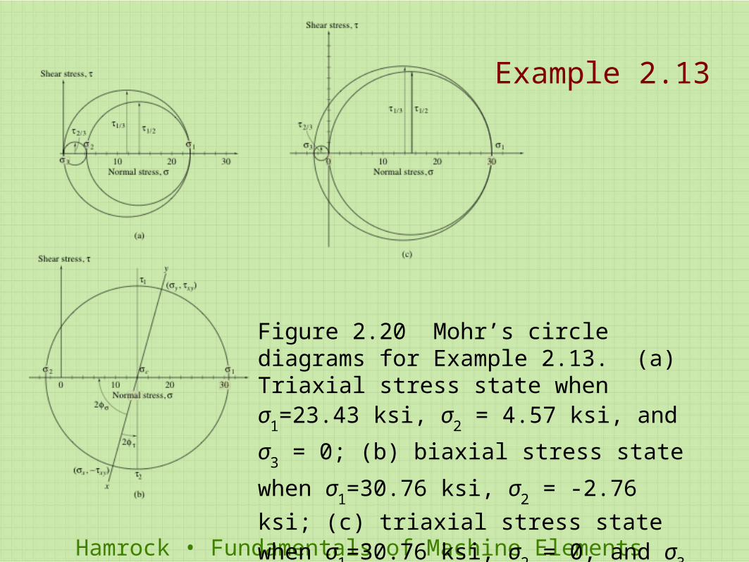
Figure 2.20 Mohr’s circle diagrams for Example 2.13. (a) Triaxial stress state when σ
1=23.43 ksi, σ
2 = 4.57 ksi, and σ
3 = 0; (b)
biaxial stress state when σ1=30.76 ksi, σ
2 = -
2.76 ksi; (c) triaxial stress state when σ1=30.76
ksi, σ2 = 0, and σ
3 = -2.76 ksi.
Example 2.13
Hamrock • Fundamentals of Machine Elements
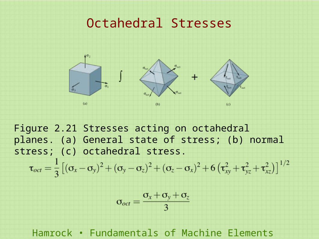
Figure 2.21 Stresses acting on octahedral planes. (a) General state of stress; (b) normal stress; (c) octahedral stress.
Octahedral Stresses
Hamrock • Fundamentals of Machine Elements
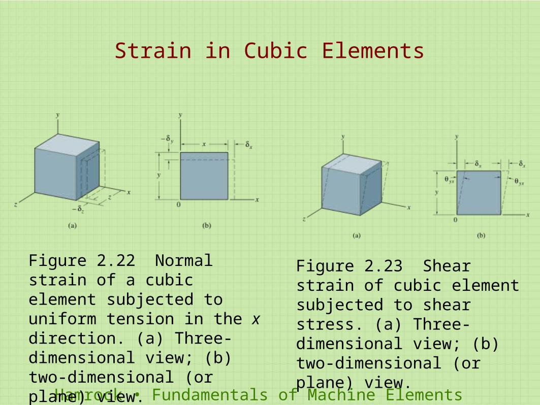
Figure 2.22 Normal strain of a cubic element subjected to uniform tension in the x direction. (a) Three-dimensional view; (b) two-dimensional (or plane) view.
Figure 2.23 Shear strain of cubic element subjected to shear stress. (a) Three-dimensional view; (b) two-dimensional (or plane) view.
Strain in Cubic Elements
Hamrock • Fundamentals of Machine Elements
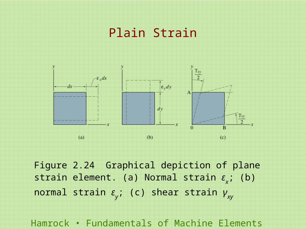
Figure 2.24 Graphical depiction of plane strain element. (a) Normal strain ε
x; (b) normal strain ε
y; (c) shear strain γ
xy
Plain Strain
Hamrock • Fundamentals of Machine Elements
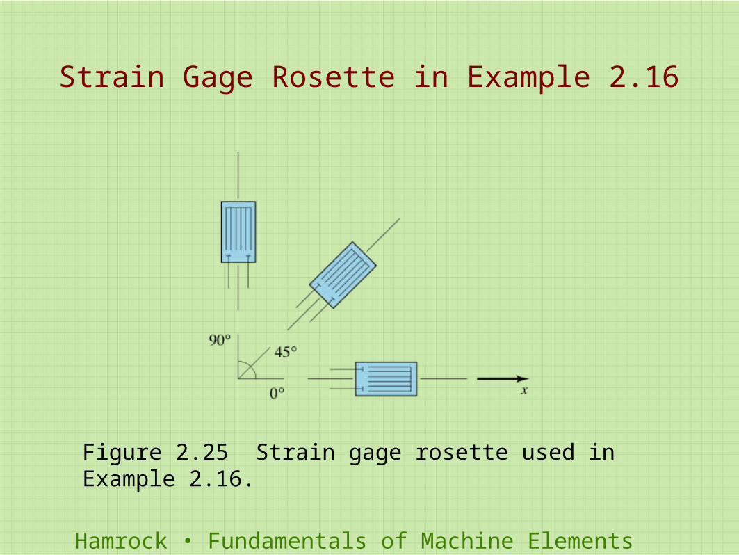
Strain Gage Rosette in Example 2.16
Figure 2.25 Strain gage rosette used in Example 2.16.
Hamrock • Fundamentals of Machine Elements
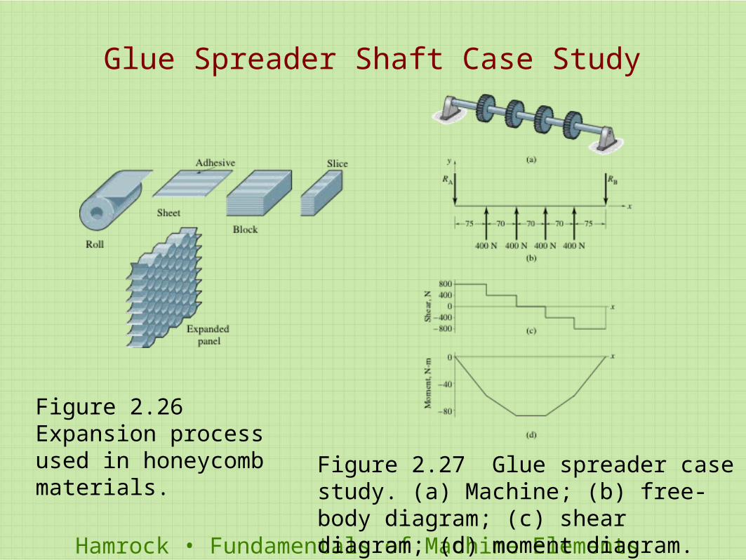
Glue Spreader Shaft Case Study
Figure 2.26 Expansion process used in honeycomb materials. Figure 2.27 Glue spreader case study. (a)
Machine; (b) free-body diagram; (c) shear diagram; (d) moment diagram.


![FILM THICKNESS MAPPING IN LUBRICATED … film thickness determination as a function of dimensionless speed and load parameter [Hamrock 1978]. Later, the equation based on](https://img.pdfslide.us/doc/110x75/5aab4ba67f8b9a693f8bb991/film-thickness-mapping-in-lubricated-film-thickness-determination-as-a-function.jpg)