Embed Size (px)
Citation preview

HAMMERUser’s Manual
Section of Biomedical Image Analysisc© SBIA, University of Pennsylvania, April 15, 2008

2
Contents
1 HAMMER Overview 7
1.1 Description . . . . . . . . . . . . . . . . . . . . . . . . . . . . . . . . 7
1.1.1 Convention for segmented images . . . . . . . . . . . . . . . . 7
1.1.2 Notes on preprocessing images for HAMMER . . . . . . . . . 8
1.2 Software Dependencies . . . . . . . . . . . . . . . . . . . . . . . . . . 9
1.3 Licensing . . . . . . . . . . . . . . . . . . . . . . . . . . . . . . . . . . 9
1.4 Features . . . . . . . . . . . . . . . . . . . . . . . . . . . . . . . . . . 10
2 Obtaining HAMMER 13
2.1 Downloads . . . . . . . . . . . . . . . . . . . . . . . . . . . . . . . . 13
2.2 Installation . . . . . . . . . . . . . . . . . . . . . . . . . . . . . . . . 13
2.2.1 Installation on a Windows system . . . . . . . . . . . . . . . . 13
2.2.2 Installation on a Linux system . . . . . . . . . . . . . . . . . . 14
3 Getting Started with HAMMER 17
3.1 Using HAMMER CLI on the sample data-set . . . . . . . . . . . . . 17
3.1.1 Labeling the sample subject’s brain using the included tem-plate/models . . . . . . . . . . . . . . . . . . . . . . . . . . . 18
3.1.2 Normalizing the sample subject’s brain using the includedtemplates/models . . . . . . . . . . . . . . . . . . . . . . . . . 19
3.1.3 Generating the RAVENS maps for the sample subject’s brain 19
3.1.4 Correct the labels generated in the labeling step . . . . . . . . 19
3.2 Using HAMMER GUI on the sample data-set . . . . . . . . . . . . . 20
3

4 CONTENTS
3.2.1 Description of the sample data-set . . . . . . . . . . . . . . . . 20
3.2.2 Creating a project for the sample data-set . . . . . . . . . . . 20
3.2.3 Using the project properties panel . . . . . . . . . . . . . . . . 24
3.2.4 Labeling the images in the data-set . . . . . . . . . . . . . . . 24
3.2.5 Correcting labels . . . . . . . . . . . . . . . . . . . . . . . . . 24
3.2.6 Normalizing the images in the data-set . . . . . . . . . . . . . 24
3.2.7 Generating RAVENS maps . . . . . . . . . . . . . . . . . . . . 25
3.2.8 Anatomy of the HAMMER GUI . . . . . . . . . . . . . . . . . 25
4 Using the HAMMER CLI 31
4.1 Labeling a subject’s brain by a manually-labeled brain model . . . . . 32
4.1.1 Required arguments . . . . . . . . . . . . . . . . . . . . . . . 32
4.1.2 Valid options . . . . . . . . . . . . . . . . . . . . . . . . . . . 32
4.1.3 Examples . . . . . . . . . . . . . . . . . . . . . . . . . . . . . 33
4.1.4 Notes . . . . . . . . . . . . . . . . . . . . . . . . . . . . . . . 33
4.2 Normalizing subject brain images . . . . . . . . . . . . . . . . . . . . 34
4.2.1 Required arguments . . . . . . . . . . . . . . . . . . . . . . . 34
4.2.2 Valid options . . . . . . . . . . . . . . . . . . . . . . . . . . . 34
4.2.3 Examples . . . . . . . . . . . . . . . . . . . . . . . . . . . . . 35
4.2.4 Notes . . . . . . . . . . . . . . . . . . . . . . . . . . . . . . . 35
4.3 Generating RAVENS maps for each tissue (WM, GM, VN) . . . . . . 36
4.3.1 Required arguments . . . . . . . . . . . . . . . . . . . . . . . 36
4.3.2 Valid options . . . . . . . . . . . . . . . . . . . . . . . . . . . 36
4.3.3 Examples . . . . . . . . . . . . . . . . . . . . . . . . . . . . . 37
4.3.4 Notes . . . . . . . . . . . . . . . . . . . . . . . . . . . . . . . 37
4.4 Group Analysis . . . . . . . . . . . . . . . . . . . . . . . . . . . . . . 38
5 Using the HAMMER GUI 39
5.1 Organizing Data and Starting HAMMER with your Own Project . . 39
5.2 Using Projects to Group Subjects . . . . . . . . . . . . . . . . . . . . 39

CONTENTS 5
5.3 Browsing the files associated to subjects in a project . . . . . . . . . 41
5.4 Perform Any Processing Step . . . . . . . . . . . . . . . . . . . . . . 42
5.5 Help . . . . . . . . . . . . . . . . . . . . . . . . . . . . . . . . . . . . 43
References 45

6 CONTENTS

1
HAMMER Overview
1.1 Description
HAMMER is an elastic registration procedure, with details in [1], [2], [3]. It isused to warp a template brain image to an individual, and vice versa. HAMMERis provided in two modalities: A HAMMER Command Line Interface (CLI) and aHAMMER Graphic User Interface (GUI). Both offer a way to perform common tasksusing the HAMMER algorithm. The Command Line Interface allows users to tosubmit jobs via job schedulers, write their own scripts to perform batch operations,etc., besides being able to simply run HAMMER on the command line. On theother hand the Graphic User Interface allows users to perform repetitive operationsfor a set of subjects with the same options with a few clicks of a mouse.
Throughout this document it is assumed that you intend to perform a warp-ing task on images that have gone trough a minimal series of preprocessing stepsdescribed in the next section. Ultimately, the images must adhere to the followingconvention.
1.1.1 Convention for segmented images
In order to make HAMMER as robust as possible to different acquisition protocolsand conditions, we provide a distribution that assumes that images have been skull-stripped and segmented into gray matter (GM), white matter (WM), and ventricularCSF. A variety of other software tools that can perform these steps, including skullstripping, reorientation and reslicing, and segmentation tools exist, some of whichcan be provided by our laboratory upon request. We use an image intensity of 250for WM, 150 for gray matter GM, 50 for ventricles and 10 for CSF in the tissue-
7

8 1. HAMMER OVERVIEW
segmented brain images. Alternatively if the model uses the same value for theentire CSF, including the ventricles, the same consideration should be allowed witheach individual image. However, in our provided model, ventricular CSF is labeledas 50 and it does make the registration more accurate; for consistency, ventricularCSF in the subjects should be also identically labeled as 50.
1.1.2 Notes on preprocessing images for HAMMER
Raw MR images should be subject to some preprocessing steps before running theHAMMER algorithm on these. The steps may include reorientation, alignment,skull stripping and tissue segmentation. Once these images have been properly pre-processed then it is possible to use HAMMER to obtain the labeling results or toproduce tissue density maps such as RAVENS maps [ref for voxel-based analysis] orto normalize subject images to a template/model image. RAVENS maps are gener-ated by using both the HAMMER-output deformation field and the tissue-segmentedbrain image as inputs. The results of performing the HAMMER algorithm can thenbe used to perform a group analysis by using a statistical analysis method such asSPM.
Skull Stripping
First of all, please check the orientation of the image. The required input imageshould be in Analyze-format following the radiology convention (left hemisphereon the right side). The header file must be included in addition to the image file.Programs like MIPAV can be used to reorient the images.
As for skull-stripping of original MR brain images, any of the following free-software can be used, if it produces a reasonable result for your data. These include:BET, which is a part of FSL , Brain Suite (from USC), MIPAV with free skull-stripping plug-in.
The cerebellum can also be removed. We have found that removal of thecerebellum yields better results in the medial temporal lobe. If the user prefers toretain it he/she must use a template with cerebellum.
Tissue segmentation
There are a lot of programs available for tissue segmentation, such as FAST (aspart of FSL) and FANTASM. Different segmentation programs use different labelsfor WM, GM, and CSF. It is recommended to follow our aforementioned segmented
1.2. SOFTWARE DEPENDENCIES 9
image conventions (250 for WM, 150 for GM, and 10 for CSF), however you mayuse your own if both, your subject and model follow the same conventions.
The ventricular CSF is labeled with a value of 10, after previous segmentation.The next step tipically segments out ventricular CSF and then labels it by using thevalue of 50.
NOTE: In order to label the ventricle correctly, it is recommended that boththe input image and the model have dimensions 256x256 in XY plane and it musthave the same orientation. MIPAV can be used to crop or pad the images.
1.2 Software Dependencies
This piece of software works on a variety of Linux and Windows systems with JRE1.5 or higher being the only extra requirement. However, for linux systems it isrecommended to have FSL 3.3.2 or higher installed.
Additionally, users may find extremely useful to have visualization tools toview the results.
Note that even though a version of FSL exists for Windows systems, this doesnot completely integrate with the Windows operative systems, instead it runs ontop of cygwin, a Linux emulator layer. As a consequence it has been decided not tointegrate HAMMER with FSL on Windows platforms.
1.3 Licensing
By using software developed by The Section of Biomedical Image Analysis (SBIA)at The University of Pennsylvania, you are agreeing to the following terms andconditions:
1. Permission is granted to use this software without charge for non-commercialresearch purposes only.
2. SBIA retains all rights and ownership of any software developed by this labo-ratory.
3. You may not redistribute the obtained software. You may create copies foryour own personal use but we ask you to refer any one else to SBIA’s website(https://www.rad.upenn.edu/sbia/software/index.html) for obtaining a copyof our software.

10 1. HAMMER OVERVIEW
4. You may not remove or alter any copyright, license or other proprietary noticesin the software.
5. You may publish papers or books using results produced using SBIA’s softwarealways providing appropriate citations.
6. The software is provided ”AS IS”. None of the authors or members of TheSection of Biomedical Image Analysis at the University of Pennsylvania assumeany liability or responsibility for the use of this software.
7. In particular, the software is for research purposes only and it has not beenevaluated for clinical use.
1.4 Features
Currently the HAMMER CLI and the HAMMER GUI can be used to perform thefollowing tasks:
• Label a subject’s brain using a model
• Normalize a subject’s brain to a given model
• Computation of RAVENS maps of a subject’s brain
• Correct labels
Additionally, the HAMMER GUI allows you to group multiple subjects into aproject where options that apply to all the subjects in a project are specified onlyonce, and then the operations mentioned above are performed on all the subjectssequentially.
Both, the CLI and the GUI allow the user to specify, the path where thetemporary files are to be written. This could be important for example when accessto local disks is faster as supposed to networked disks. This feature also helps tokeep intermediate results some what controlled, as these can occupy large disk spaceovertime.
The CLI has a clean function that simply deletes all the forgotten intermediateresults in the default path: user’s home/.hammer/. The GUI however always cleansup after itself before exiting, unless instructed otherwise via the keep intermediateresults option.
The intermediate results include log files that can be useful in tracking erro-neous processes; the CLI produces one log file per action, while the GUI produces

1.4. FEATURES 11
one log file per session. Is important to note again that this log file will be deletedtogether with all the other intermediate results on clean up, unless the option tokeep intermediate results is used.

12 1. HAMMER OVERVIEW

2
Obtaining HAMMER
2.1 Downloads
• Linux and Windows distributions: https://www.rad.upenn.edu/sbia/software/index.html#hammer
• Sample data set (For the CLI): https://www.rad.upenn.edu/sbia/distributions/hammer/sample/sample.zip
• Sample data set (For the GUI): https://www.rad.upenn.edu/sbia/distributions/hammer/sample/sample_batch.zip
• Sample models: https://www.rad.upenn.edu/sbia/distributions/hammer/models/models.zip
2.2 Installation
HAMMER can be installed on Windows XP, Windows 2000 and Linux.
2.2.1 Installation on a Windows system
Before installing HAMMER please make sure that you have previously installedJava JRE 1.5 or higher. Both the CLI and the GUI depend on it to work.
After a proper version of Java is available in the system, install HAMMER ona Windows System by simply downloading the installer [2.1], and double clicking onit. Select a path where to install the software and click OK.
13

14 2. OBTAINING HAMMER
2.2.2 Installation on a Linux system
The installation on a Linux system is a little more manual and it involves thefollowing steps:
• Install the prerequisites:
– If needed, install Java (JRE 1.5 or higher) following these instructions:
http://java.com/en/download/index.jsp .
– If needed, install FSL following these instructions:
http://www.fmrib.ox.ac.uk/fsl/fsl/downloading.html
• Download the linux version following the link provided earlier in this document[2.1].
• Unpack the tarball in the desired application folder. Note that you may needadministrator privileges in the machine if the path is not under the user’s homedirectory.
• Set the PATH environment. This would depend on the particular shell thatyou are using. For example, the following lines can be added at the end of your.profile or .bashrc file, where it is assumed that you want to install everythingin the folder /home/username/Applications, and ’username’ is replaced byyour username.
# The next l i n e s add f s l to the path
FSLDIR=/home/username/ App l i ca t i on s / f s l. ${FSLDIR}/ e tc / f s l c o n f / f s l . shPATH=${FSLDIR}/ bin : ${PATH}export FSLDIR PATH
# The next l i n e s add HAMMER to the path
HAMMERDIR=/home/username/ App l i ca t i on s /hammerPATH=${HAMMERDIR}/hammergui/ bin : ${PATH}PATH=${HAMMERDIR}/ bin : ${PATH}export HAMMERDIR PATH
It is strongly recommended that you go over the section [3] that describes howto get started using the sample data referenced in the downloads section [2.1].

2.2. INSTALLATION 15
This will not only check that your system is ready to run HAMMER, but alsowill allow you to become familiar with the basic assumptions for images and projectstructures.

16 2. OBTAINING HAMMER
3
Getting Started with HAMMER
This section shows you in detail how to get started with HAMMER using the sampledata that can be downloaded from the web [2.1], the detailed steps here make useof the default options, if you wish to obtain more information about each of theoptions please refer to the Using HAMMER section [4].
Depending on your interests you may wish to review either or both of thefollowing sections that describe how to get started using the CLI and the GUI.
For the CLI use the data-set that includes only one subject, for the GUI itis recommended that you use the data-set that includes a few subjects so that youunderstand how the GUI expects you to organize your subjects and to get familiarwith the project processing.
3.1 Using HAMMER CLI on the sample data-set
Before running HAMMER with your subjects take a moment to run HAMMERusing the sample data provided [2.1]. Also, make sure that you have a workinginstallations of Java 1.5 or higher by typing at the shell: java -version . Update yourversion of java if needed or if you have already installed Java 1.5 or later then makesure that you edit your Java PATH in .profile or .bashrc file. FSL is recommendedand you can test if is properly installed by typing in the shell: fsl . Figure [3.1]shows a terminal where the user checks for the environment configuration
It is recommended that you run a test for each of the following four tasks:
• Label the sample subject’s brain using the included template/models
• Normalize the sample subject’s brain using the included templates/models
17

18 3. GETTING STARTED WITH HAMMER
Figure 3.1: A terminal screen showing that my environment is properly configured.
• Generate the RAVENS maps for the sample subject’s brain
• Correct the labels generated in the labeling step
In order to perform this test, download the models and sample dataset fromthe sources listed earlier in this document [2.1].
Unzip the contents to folder of your choice and then run the following com-mands to perform each of the tests accordingly.
3.1.1 Labeling the sample subject’s brain using the includedtemplate/models
In order to label the sample subject’s brain using the included templates you simplyneed to run the following command on a terminal from the directory where thesample images were unzipped. Note that if you are using a windows system youhave to use the “HAMMER CLI” that should be found on your programs menuafter a successful installation.

3.1. USING HAMMER CLI ON THE SAMPLE DATA-SET 19
$ hammer l a b e l b r a i n −S sub j e c t s egmented no ce r e . img−M jakob rad convent i on segmented no ce re . img−L j a k o b r a d c o n v e n t i o n l a b e l s n o c e r e . img
3.1.2 Normalizing the sample subject’s brain using the in-cluded templates/models
In order to normalize the sample subject’s brain using the included template yousimply need to run the following command on a terminal from the directory wherethe sample images were unzipped. Note that if you are using a windows system youhave to use the “HAMMER CLI” that should be found on your programs menuafter a successful installation.
$ hammer normal i z ebra in −S sub j e c t s egmented no ce r e . img−O s u b j e c t o r i g i n a l w i t h c e r e . img−M jakob rad convent i on segmented no ce re . img−L j a k o b r a d c o n v e n t i o n l a b e l s n o c e r e . img
3.1.3 Generating the RAVENS maps for the sample sub-ject’s brain
To generate the RAVENS maps for the sample subject’s brain using the includedtemplates you simply need to run the following command on a terminal from thedirectory where the sample images were unzipped. Note that if you are using awindows system you have to use the “HAMMER CLI” that should be found onyour programs menu after a successful installation.
$ hammer ravens −S sub j e c t s egmented no ce r e . img−M jakob rad convent i on segmented no ce re . img
3.1.4 Correct the labels generated in the labeling step
Finally to correct the label image that was generated in the first step run the follow-ing command on a terminal from the directory where the sample images were un-zipped. Note that if you are using a windows system you have to use the “HAMMERCLI” that should be found on your programs menu after a successful installation.

20 3. GETTING STARTED WITH HAMMER
$ hammer c o r r e c t l a b e l s −S sub j e c t s egmented no ce r e . img−L sub j e c t s egmented no ce r e . img . Warped . Labels . img−O sub j e c t s egmented no ce r e . img . Warped . Labe l sCorrected . img
3.2 Using HAMMER GUI on the sample data-set
Before you start using the HAMMER GUI you should make sure you have it properlyinstalled in your system. Additionally, for this section you will need the sample_
batch.zip and models.zip archives containing the sample project data-set andmodels referenced in the downloads section [2.1].
If you installed HAMMER successfully, you should be able to start the HAM-MER GUI by typing at the prompt:
$ hammergui
Or by clicking on the HAMMER GUI menu entry on a Windows system.
3.2.1 Description of the sample data-set
The sample data set is contained in the sample_batch.zip (see downloads for alink to obtain this). Figure [3.2] shows the file structure of the sample project afteruncompressing the archive.
The cbq images have gone trough a minimum of preprocessing steps, suchas conversion to Analyze format, ACPC alignment, pading, etc. Additionally, thepreprocessed images have already been segmented to meet the image requirementsfor HAMMER [1.1.1].
Use your favorite Analyze format image viewer to take a look at the images.
3.2.2 Creating a project for the sample data-set
With HAMMER open, as shown in figure [3.3], follow these steps:
• If it is not already open, open a Project Manager Window (Window→ ProjectManager)
• Right click on the Hammer Projects folder of the Project Manager.

3.2. USING HAMMER GUI ON THE SAMPLE DATA-SET 21
Figure 3.2: A file browser showing the structure of the batch sample project.
• Select and click on the Add Project option of the pop up menu.
• A New Project Form will appear in the main panel, this, as well as any otherpanel can be made to use the whole window by simply double clicking on itscorresponding tab as shown on figure [3.4](this one also displays an × thatis used to close the panel.) By double clicking on the tab a second time, thepanel returns to its initial position using only a portion of the main window.As you become more familiar, you will see that the panels can be rearrangedto suit your preferences.
• Fill the New Project Form with the the default parameters, as follows:
– Give a name to your project. This has to be unique among the projectson the same folder and must not contain any special character that cannot be included on a file name.
– Provide the path for the subjects directory inside sample_batch, thatis, the sample data set that was described earlier.
– Provide the path for the model folder resulting from unzipping the men-tioned archive. This path should contain all the models that will be usedby the registration algorithms.
– Select a working path, for example the working folder in figure [3.2] .This path will be used to place some temporary results and files. Logexecution files will also be placed in this path. Note, a subfolder will be

22 3. GETTING STARTED WITH HAMMER
Figure 3.3: HAMMER GUI when it is opened for the first time.
created for each subject, and this folder will contain all the intermediateresults corresponding to the processing of this subject.
– Specify the path for the segmented model that will be used during themultiple advanced processing steps. Select jakob_rad_convention_segmented_no_cere.img from the HAMMER distribution models.
– Specify the path for the label model that will be used during the multipleadvanced preprocessing steps. Select jakob_rad_convention_labels_
no_cere.img from the HAMMER distribution models.
– Leave the Linear Transformation Field empty. This field would onlybe used by experienced users that have already precomputed a lineartransformation and they wish to use it here.
– Leave the default input suffix. This is the suffix that input images areexpected to have. Other images will not be processed.
– Leave the default preprocessed suffix. This is the suffix that preprocessedimages will have. Ultimately images with this suffixes will be processedby hammer. NOTE: Even if your images have been segmented alreadythey need to be preprocessed, therefore only preprocessed images thathave corresponding input images will be processed by hammer.
– Leave the default neighborhood search sizes. The neighborhood searchsize is different at each resolution. The defaults are: <12,10,8> mm/vox-els for <value_at_low,value_at_middle,value_at_high>
– Set to <10,10,10> the number of warping iterations for low, mid andhigh resolutions. This is the number of iterations in each of the warping

3.2. USING HAMMER GUI ON THE SAMPLE DATA-SET 23
Figure 3.4: The New Project Form.
stages. It is recommended that your use <50,50,50> for best resultsbut for the purpose of illustrating the functionality, 10 iterations in eachstage are good enough and would take less time to process.
– Leave the default deformation step ratio. This is the step ratio used inthe warping step.
– Leave the default matching degree. This is the similarity degree that willbe used during the warping step.
– Leave the default keep intermediate results option.
– If you are using Linux and have FSL installed you can select the FSLoption.
– Leave the default number of smoothing iterations. This is the number ofsmoothing iterations that will be used in the RAVENS maps generation.
– Leave the default number of edge preserving iterations.
– Leave the default deformation field smoothing factor.
– Leave the intensity values for VN, GM, WM. These are the values thatwill be assigned to ventricles, gray matter and white matter respectively.
– Leave the default ravens scale factor.
– Leave the default number of RAVENS resampling iterations.
– Click on Create Project to finish the project creation.
Note that the set of RAVENS options only apply if what you want to do is tocompute RAVENS maps, otherwise you do not need to pay attention to them.
24 3. GETTING STARTED WITH HAMMER
3.2.3 Using the project properties panel
The properties panel can be accessed by either right clicking on a project name (onthe project tree) or by clicking on the (Window → Properties), which will displaythe properties of the selected project. The properties panel will allow the user toedit any of the properties of the selected project.
3.2.4 Labeling the images in the data-set
To perform the labeling step for the sample data set follow these steps:
• Select the sample project from the Project Manager Window.
• Click on (Tools → Perform Labeling Step). This will use HAMMER to warpthe model to each of the subject images using the label model.
After the warping step with input subject*_preprocessed.img one gets theadditional files shown in figure [3.5]. The subjects are warped one by one.
3.2.5 Correcting labels
Some times the label image created in the previous step need s some correction, todo so, simply click on (Tools → Perform Label Correction Step).
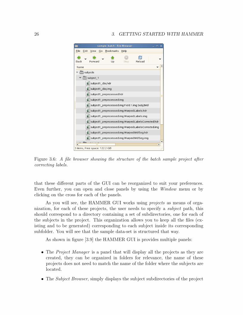
After the correction step we have the files listed on figure [3.6].
3.2.6 Normalizing the images in the data-set
To normalize all the subjects in the sample data-set to the segmented model followthese steps:
• Select the sample project from the Project Manager Window.
• Click on (Tools → Perform Normalization Step). This will use HAMMER towarp all the preprocessed subject images to the segemented model.
After running the normalization step with input subject*_preprocessed.img onegets the additional files shown in figure [3.7]. The subjects are warped one by one.

3.2. USING HAMMER GUI ON THE SAMPLE DATA-SET 25
Figure 3.5: A file browser showing the structure of the batch sample project afterlabeling.
3.2.7 Generating RAVENS maps
To generate RAVENS maps follow these steps:
• Select the sample project from the Project Manager Window.
• Click on (Tools → Perform Ravens Map Step). This will use HAMMERto warp all the preprocessed subject images to the segemented model, andgenerate RAVENS maps for VN, GM, and WM.
After the process is finished we should have the additional files listed on figure [3.8].The subjects are warped one by one.
3.2.8 Anatomy of the HAMMER GUI
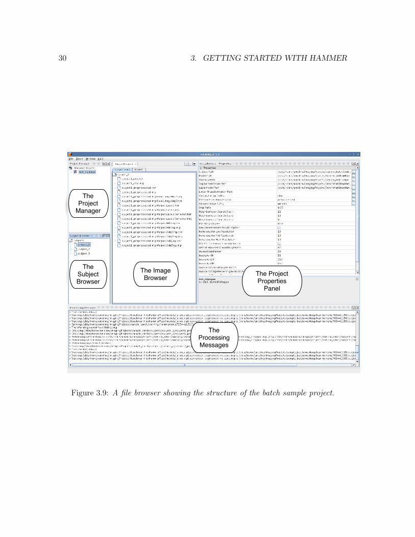
The figure [3.9] shows you a typical view of the HAMMER GUI, showing you thedifferent parts of the GUI using the default settings. You will quickly notice however
26 3. GETTING STARTED WITH HAMMER
Figure 3.6: A file browser showing the structure of the batch sample project aftercorrecting labels.
that these different parts of the GUI can be reorganized to suit your preferences.Even further, you can open and close panels by using the Window menu or byclicking on the cross for each of the panels.
As you will see, the HAMMER GUI works using projects as means of orga-nization, for each of these projects, the user needs to specify a subject path, thisshould correspond to a directory containing a set of subdirectories, one for each ofthe subjects in the project. This organization allows you to keep all the files (ex-isting and to be generated) corresponding to each subject inside its correspondingsubfolder. You will see that the sample data-set is structured that way.
As shown in figure [3.9] the HAMMER GUI is provides multiple panels:
• The Project Manager is a panel that will display all the projects as they arecreated, they can be organized in folders for relevance, the name of theseprojects does not need to match the name of the folder where the subjects arelocated.
• The Subject Browser, simply displays the subject subdirectories of the project

3.2. USING HAMMER GUI ON THE SAMPLE DATA-SET 27
currently working on. To populate this panel simply right click on an existingproject and select the Load Project option. Clicking on a subject folder willdisplay its contents in the Subject Files tab of the Image Browser.
• The Image Browser panel simply displays the contents of the selected subject’sfolder in the Subject Browser, and the models associated to the current project.Additionally, in Linux, double clicking on an image will open it with the FSLviewer if it is installed.
• The Project Properties panel shows the properties of the selected project. Thispanel is not open by default, to open it simply click on the Properties itemof the Window menu, or open a floating version of it by right clicking on aproject in the Project Manager and selecting the Properties item. This panelwill also allow you to modify the options for the project. Note however thatif you modify any of these options while HAMMER is processing, the optionwill only be applied to subsequent executions of it.
• Finally, the Processing Messages panel will display a short descriptive messageof what HAMMER is currently doing. The detail messages can be found inthe log files, if the user selected the keep intermediate results option.

28 3. GETTING STARTED WITH HAMMER
Figure 3.7: A file browser showing the structure of the batch sample project afternormalization.

3.2. USING HAMMER GUI ON THE SAMPLE DATA-SET 29
Figure 3.8: A file browser showing the structure of the batch sample project after theRAVENS maps are generated.
30 3. GETTING STARTED WITH HAMMER
The Image Browser
The Subject Browser
The Project
Manager
The Project Properties
Panel
The Processing Messages
Figure 3.9: A file browser showing the structure of the batch sample project.

4
Using the HAMMER CLI
This section describes in detail how to perform each of the three main tasks imple-mented in the HAMMER CLI: labeling a subject’s brain by a manually-labeled brainmodel, normalizing and computation of RAVENS maps for subject brain imagesthat have already been preprocessed to meet the brain image conventions describedearlier [1.1.1].
The general syntax for the HAMMER CLI is the following:
hammer <subcommand> [ subcommand arguments and opt ions ]
Where the subcommand is one of the following:
• labelbrain
• normalizebrain
• ravens
The subcommand-arguments are a set of required-arguments and options.These vary depending on the subcommand, and they will be explained next. Addi-tionally, it is possible to run
hammer help <subcommand>
This would display help for the usage of the given subcommand.
31

32 4. USING THE HAMMER CLI
4.1 Labeling a subject’s brain by a manually-labeled
brain model
In order to label a subject’s brain by a manually-labeled brain model you simplyneed to run the following command:
hammer l a b e l b r a i n −S <subject image> −M <model image>−L <l abe l image > [ opt i ons ]
4.1.1 Required arguments
• -S [string] : Segmented subject image file name. This must be the absolutepath, if it is not in the current working directory. This must be an image inAnalyze format of byte type, tissue segmented and with a header. Provide thepath for the image and not the header’s. Note that the x and y dimensionsmust be equal.
• -M [string] : Segmented model image file name. This must be the absolutepath, if it is not in the current working directory. This must be an image inAnalyze format of byte type, tissue segmented and with a header. Provide thepath for the image and not the header’s. Note that the x and y dimensionsmust be equal.
• -L [string] : Label model image file name. This must be the absolute path, ifit is not in the current working directory. This must be an image in Analyzeformat of byte type, tissue segmented and with a header. Provide the pathfor the image and not the header’s. Note that the x and y dimensions mustbe equal.
4.1.2 Valid options
• -A [string] : Global affine transformation to use in the rigid transformationstage. If this is provided, then it will not be regenerated. This transformationmust be in the SBIA compatible format.
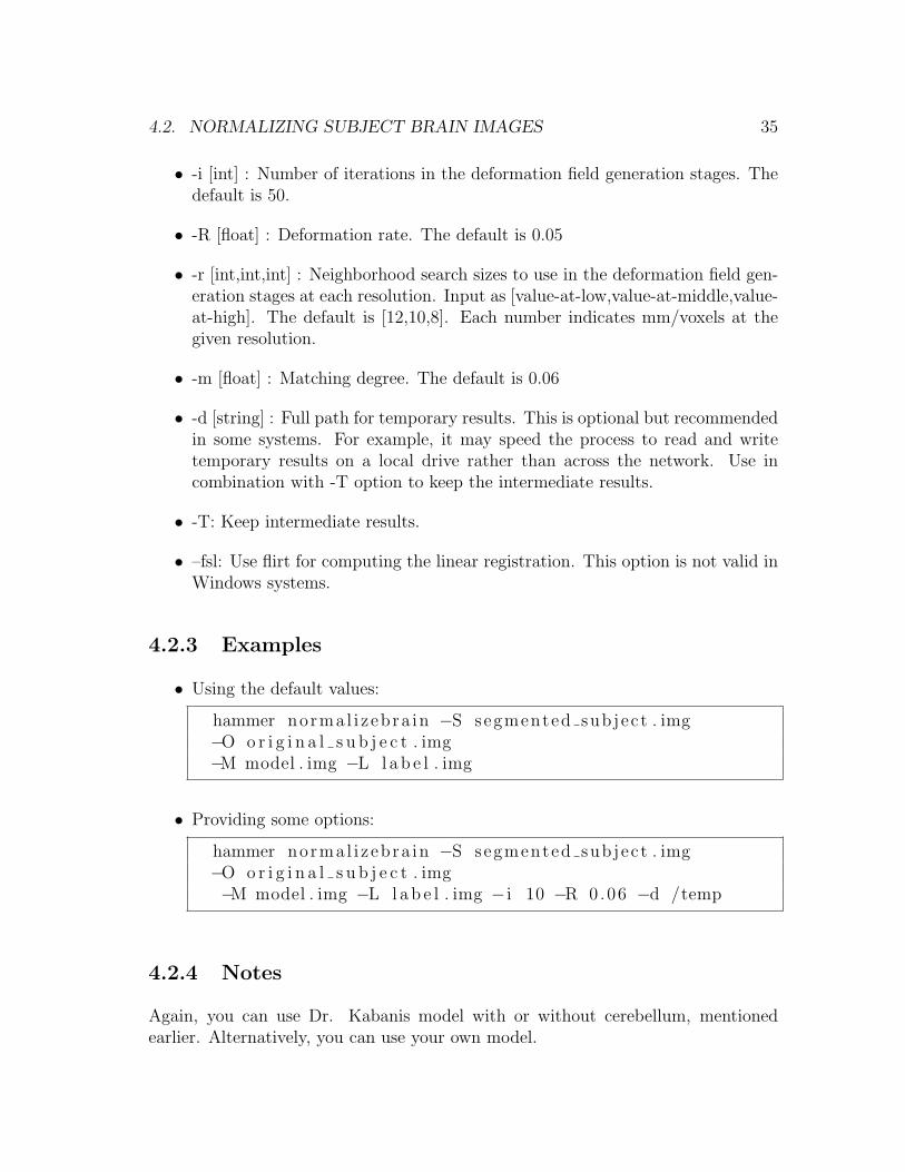
• -i [int] : Number of iterations in the deformation field generation stages. Thedefault is 50.
• -R [float] : Deformation rate. The default is 0.05

4.1. LABELING A SUBJECT’S BRAIN BY A MANUALLY-LABELED BRAIN MODEL33
• -r [int,int,int] : Neighborhood search sizes to use in the deformation field gen-eration stages at each resolution. Input as [value-at-low,value-at-middle,value-at-high]. The default is [12,10,8]. Each number indicates mm/voxels at thegiven resolution.
• -m [float] : Matching degree. The default is 0.06
• -d [string] : Full path for temporary results. This is optional but recommendedin some systems. For example, it may speed the process to read and writetemporary results on a local drive rather than across the network. Use incombination with -T option to keep the intermediate results.
• -T: Keep intermediate results.
• –fsl: Use flirt for computing the linear registration. This option is not valid inWindows systems.
4.1.3 Examples
• Using the default values:
hammer l a b e l b r a i n −S sub j e c t . img −M model . img−L l a b e l . img
• Providing some options:
hammer l a b e l b r a i n −S sub j e c t . img −M model . img−L l a b e l . img − i 10 −R 0.06 −d /temp
4.1.4 Notes
You can use your own label template, or you can use the template that comeswith the package. This label model was developed by Dr. Kabani at the MontrealNeurological Institute, including 101 regions of interest. Note that, if you use Dr.Kabani’s template you must acknowledge it using the following reference [ref]. Thisdocument provided a link earlier to get the model. Use the images with or withoutcerebellum to match your particular situation.

34 4. USING THE HAMMER CLI
4.2 Normalizing subject brain images
In order to normalize the subject image to the space of the model image run thefollowing command:
hammer normal i z ebra in −S <segmented subject image>−O <o r i g i n a l s u b j e c t i m a g e > −M <segmented model image>−L <l abe l image > [ opt i ons ]
4.2.1 Required arguments
• -S [string] : Segmented subject image file name. This must be the absolutepath, if it is not in the current working directory. This must be an image inAnalyze format of byte type, tissue segmented and with a header. Provide thepath for the image and not the header’s. Note that the x and y dimensionsmust be equal.
• -O [string] : Original subject image file name. This must be the absolute path,if it is not in the current working directory. This must be an image in Analyzeformat of byte type, tissue segmented and with a header. Provide the pathfor the image and not the header’s. Note that the x and y dimensions mustbe equal.
• -M [string] : Segmented model image file name. This must be the absolutepath, if it is not in the current working directory. This must be an image inAnalyze format of byte type, tissue segmented and with a header. Provide thepath for the image and not the header’s. Note that the x and y dimensionsmust be equal.
• -L [string] : Label model image file name. This must be the absolute path, ifit is not in the current working directory. This must be an image in Analyzeformat of byte type, tissue segmented and with a header. Provide the pathfor the image and not the header’s. Note that the x and y dimensions mustbe equal.
4.2.2 Valid options
• -A [string] : Global affine transformation to use in the rigid transformationstage. If this is provided, then it will not be regenerated. This transformationmust be in the SBIA compatible format.
4.2. NORMALIZING SUBJECT BRAIN IMAGES 35
• -i [int] : Number of iterations in the deformation field generation stages. Thedefault is 50.
• -R [float] : Deformation rate. The default is 0.05
• -r [int,int,int] : Neighborhood search sizes to use in the deformation field gen-eration stages at each resolution. Input as [value-at-low,value-at-middle,value-at-high]. The default is [12,10,8]. Each number indicates mm/voxels at thegiven resolution.
• -m [float] : Matching degree. The default is 0.06
• -d [string] : Full path for temporary results. This is optional but recommendedin some systems. For example, it may speed the process to read and writetemporary results on a local drive rather than across the network. Use incombination with -T option to keep the intermediate results.
• -T: Keep intermediate results.
• –fsl: Use flirt for computing the linear registration. This option is not valid inWindows systems.
4.2.3 Examples
• Using the default values:
hammer normal i z ebra in −S segmented subject . img−O o r i g i n a l s u b j e c t . img−M model . img −L l a b e l . img
• Providing some options:
hammer normal i z ebra in −S segmented subject . img−O o r i g i n a l s u b j e c t . img−M model . img −L l a b e l . img − i 10 −R 0.06 −d /temp
4.2.4 Notes
Again, you can use Dr. Kabanis model with or without cerebellum, mentionedearlier. Alternatively, you can use your own model.

36 4. USING THE HAMMER CLI
4.3 Generating RAVENS maps for each tissue (WM,
GM, VN)
To register subject and model images, obtaining a deformation field and threeRAVENS maps run the following command:
hammer ravens −S <subject image> −M <model image> [ opt i ons ]
4.3.1 Required arguments
• -S [string] : Segmented subject image file name. This must be the absolutepath, if it is not in the current working directory. This must be an image inAnalyze format of byte type, tissue segmented and with a header. Provide thepath for the image and not the header’s. Note that the x and y dimensionsmust be equal.
• -M [string] : Segmented model image file name. This must be the absolutepath, if it is not in the current working directory. This must be an image inAnalyze format of byte type, tissue segmented and with a header. Provide thepath for the image and not the header’s. Note that the x and y dimensionsmust be equal.
4.3.2 Valid options
• -A [string] : Global affine transformation to use in the rigid transformationstage. If this is provided, then it will not be regenerated. This transformationmust be in the SBIA compatible format.
• -i [int] : Number of iterations in the deformation field generation stages. Thedefault is 50.
• -R [float] : Deformation rate. The default is 0.05
• -r [int,int,int] : Neighborhood search sizes to use in the deformation field gen-eration stages at each resolution. Input as [value-at-low,value-at-middle,value-at-high]. The default is [12,10,8]. Each number indicates mm/voxels at thegiven resolution.
• -m [float] : Matching degree. The default is 0.06
• -c [float] : Deformation filed smoothing factor. The default is 0.5

4.3. GENERATING RAVENS MAPS FOR EACH TISSUE (WM, GM, VN) 37
• -C [int] : Number of smoothing iterations. The default is 1
• -E [int] : Number of edge preserving smoothing iterations. The default is 30
• -l [int,int,int] : Intensities for [WM,GM,VN]. The default is [150,250,50]
• -F [int] : RAVENS scale factor. The default is 20
• -a [int] : Number of RAVENS re sampling iterations. The default is 1
• -d [string] : Full path for temporary results. This is optional but recommendedin some systems. For example, it may speed the process to read and writetemporary results on a local drive rather than across the network. Use incombination with -T option to keep the intermediate results.
• -T: Keep intermediate results.
• –fsl: Use flirt for computing the linear registration. This option is not valid inWindows systems.
4.3.3 Examples
• Using the default values:
hammer ravens −S sub j e c t . img −M model . img
• Providing some options:
hammer ravens −S sub j e c t . img −M model . img − i 10−R 0.06 −d /temp
4.3.4 Notes
Running this subcommand would perform two tasks. It uses HAMMER to registersubject brain with the model brain, and then uses the HAMMER-output deforma-tion field and the tissue-segmented image of the subject to generate tissue-densitymaps (i.e., RAVENS maps) [ref]. Higher RAVENS map implies more tissue volumeat a given location in the template space. Reference [] describes the principle of atissue density map in detail, and describes how it can be used for voxel-based analy-sis. For convenience, we combine the two previous steps into a single script program.The input to this program is the tissue-segmented image, with ventricle having beenlabeled as 50 . The outputs are a deformation field pointing from subject to model,
38 4. USING THE HAMMER CLI
and three RAVENS maps for each tissue such as WM, GM, and VN density maps.This works using other models as well, as long as the tissue segmentation is samefor both model and subject, with labels 250 for WM, 150 for GM, and 10 for CSF.
4.4 Group Analysis
The RAVENS maps can be used for group analysis, by using an image analysistool such as SPM. Typically these RAVENS maps are smoothed by a Gaussian oredge-preserving filter of 5-10mm, subsequently, a statistical analysis that dependson the underlying scientific question is applied to the soothed RAVENS maps. Forexample, if we want to investigate local volumetric differences in GM between agroup of patients and a group of normal controls, we might want to apply a vowel-*t-test on the smoothed RAVENS GM maps.

5
Using the HAMMER GUI
5.1 Organizing Data and Starting HAMMER with
your Own Project
HAMMER uses suffixes to determine what type of treatment gets each file. Theuser specifies these suffixes when creating a HAMMER project.
In particular there is an input suffix, which in the example was chosen as cbq.That means that once it is specified in the options that this is the suffix for the inputimages, then only images that look like myImageName_cbq.img and their derived willbe processed while performing the HAMMER steps.
It is assumed that all the subjects to be processed with the same settings arein one folder in the user’s system, preferably organized in subfolders so that onlyone input image is in each folder. This last thing is not a requirement but it helpsthe HAMMER GUI to keep things organized. In particular when browsing the filesby subject, the Hammer Suite will assume that there is a one-to-one correspondencebetween subfolders and subjects.
5.2 Using Projects to Group Subjects
The HAMMER GUIis structured to group subjects and settings into projects. Theseprojects can be further grouped into folders.
1. To create a new project follow these steps:
• If it is not already open, open a Project Manager Window (Window →
39

40 5. USING THE HAMMER GUI
Project Manager)
• Right click on the Hammer Projects folder of the Project Manager.
• Select and click on the Add Project option of the pop up menu.
• Fill the New Project Form with your project parameters, as follows:
– Give a name to your project. This has to be unique among theprojects on the same folder and must not contain any special char-acter that can not be included on a file name.
– Provide the path for the subjects directory inside sample_batch,that is, the sample data set that was described earlier.
– Provide the path for the model folder resulting from unzipping thementioned archive. This path should contain all the models that willbe used by the registration algorithms.
– Select a working path, for example the working folder in figure [3.2]. This path will be used to place some temporary results and files.Log execution files will also be placed in this path.
– Specify the path for the segmented model that will be used during themultiple advanced processing steps. Select jakob_rad_convention_segmented_no_cere.img from the HAMMER distribution models.
– Specify the path for the label model that will be used during the mul-tiple advanced preprocessing steps. Select jakob_rad_convention_
labels_no_cere.img from the HAMMER distribution models.
– Specify the linear transformation path if you have pre-computed itbefore, else leave it blank. This feature would allow you to reuse apreviously computed transformation.
– Specify the input suffix. This is the suffix that original images areexpected to have. Other images will not be processed.
– Specify the preprocessed suffix. This is the suffix that preprocessedimages will have. Ultimately images with this suffixes will be pro-cessed by hammer.
– Specify the neighborhood search sizes. The neighborhood search sizeis different at each resolution. The defaults are: <12,10,8> mm/vox-els for <value_at_low,value_at_middle,value_at_high>
– Specify the number of warping iterations for low, mid and high reso-lutions. This is the number of iterations in each of the warping stages.It is recommended that your use <50,50,50> for best results.
– Specify the deformation step ratio. This is the step ratio used in thewarping step.
– Specify the matching degree. This is the similarity degree that willbe used during the warping step.

5.3. BROWSING THE FILES ASSOCIATED TO SUBJECTS IN A PROJECT41
– Select wether to delete the intermediate results or not.
– If you are using Linux and have FSL installed you can select theFSL option. NOTE: Even if you have installed FSL on Windowsthis option is not supported. FSL relies on cygwin to work which inparticular simulates a UNIX-like file system which is not compatiblewith Windows.If you intend to compute RAVENS maps also:
– Specify the number of smoothing iterations. This is the number ofsmoothing iterations that will be used in the RAVENS maps gener-ation.
– Specify the number of edge preserving iterations.
– Specify the deformation field smoothing factor.
– Specify the intensity values for VN,GM,WM. These are the valuesthat will be assigned to ventricles, gray matter and white matterrespectively.
– Specify the ravens scale factor.
– Specify the number of RAVENS resampling iterations.
– Select if you want the output in short format and if you want to usesubvolumes during the computation.
– Click on Create Project to finish the project creation.
2. To load the files of project follow these steps:
• If it is not already open, open a Project Manager Window (Window →Project Manager)
• Select a project and right click on it.
• Select and click on the Load Project Files option of the pop up menu.
3. To delete a project follow these steps:
• If it is not already open, open a Project Manager Window (Window →Project Manager)
• Select a project and right click on it.
• Select and click on the Delete option of the pop up menu.
5.3 Browsing the files associated to subjects in a
project
To populate the Image Browser Window follow these steps:

42 5. USING THE HAMMER GUI
• Load project files
• If it is not already open, open a Subject Browser Window (Window→ SubjectBrowser)
• Select any subject on the Subject Browser Window. This will populate theImage Browser Window with the images found in the selected subject’s folder.
5.4 Perform Any Processing Step
To perform any of the processing steps in the pipeline follow these steps:
• Select a project from the Project Manager Window.
• Click on (Tools→ Processing Action). This will schedule the selected process-ing over all the subjects in a project using the project options. Replace theProcessing Action by any of the following:
– Perform Labeling Step to warp the segmented model to each of the sub-jects in the set, assuming that the subject images have been properlypreprocessed.
– Perform Normalization Stepto warp each of the subjects in the set to thesegmented model, assuming that the subject images have been properlypreprocessed.
– Perform Ravens Map Step to generate RAVENS maps for each of thesubjects in the set for VN, GM and WM , assuming that the subjectimages have been properly preprocessed.
– Perform Label Correction Step to perform only the label correction stepfor each of the subjects in the set, assuming that the labeling step hasalready been performed.

44 5. USING THE HAMMER GUI

References
[1] D. Shen and C. Davatzikos. HAMMER: Hierarchical attribute matchingmechanism for elastic registration IEEE Transactions on Medical Imaging,vol. 21, pp. 1421-1439, 2002.
[2] D. G. Shen and C. Davatzikos Very high resolution morphometry us-ing mass-preserving deformations and HAMMER elastic registrationNeuroImage, vol. 18, pp. 28-41, 2003.
[3] C. Davatzikos, A. Genc, D. Xu, and S. M. Resnick. Voxel-Based Morphom-etry Using the RAVENS Maps: Methods and Validation Using Sim-ulated Longitudinal Atrophy NeuroImage, vol. 14, pp. 1361-1369, 2001.
45