Embed Size (px)
Citation preview
Hamburg Dog Bots Team Report 2005
Universitat HamburgMIN-Fakultat/Informatik
Arbeitsbereich Technische InformatiksystemeVogt-Kolln-Strasse 30
22527 Hamburg, Germanyhttp://www.hamburgdogbots.de
Team Leader: Birgit Koch([email protected])
Nils Bertling, Joachim Dubber, Sonia Haiduc, Birgit Koch,Valerij Krichevskyi, Matthias Niess, Jonas Reese, Peter Roßmeyer,
Janis Schonefeld, Gunnar Selke, Benjamin Seppke, Malte-Nils Sorensen
Abstract
In this report we give an overview over the research and the team of the HamburgDog Bots. The team is composed of undergraduate and graduate students ofthe Universitat Hamburg and Technische Universitat Hamburg-Harburg. Weparticipated for the second year the SONY Fourlegged league, but were usingERS-7 SONY Aibo robots for the first time. The report covers the history of theteam, our approaches to the technical challenges, as well as a brief descriptionof the relevant topics of research and the student research papers in the year2005.
Contents
1 Team Development 31.1 Team Members . . . . . . . . . . . . . . . . . . . . . . . . . . . . 31.2 Team History . . . . . . . . . . . . . . . . . . . . . . . . . . . . . 3
2 Challenges 42.1 Variable Lighting Challenge . . . . . . . . . . . . . . . . . . . . . 42.2 Free Challenge . . . . . . . . . . . . . . . . . . . . . . . . . . . . 62.3 Almost SLAM Challenge . . . . . . . . . . . . . . . . . . . . . . . 6
3 Topics of Research 73.1 Low-level Vision . . . . . . . . . . . . . . . . . . . . . . . . . . . 73.2 Behavior . . . . . . . . . . . . . . . . . . . . . . . . . . . . . . . . 83.3 Motion . . . . . . . . . . . . . . . . . . . . . . . . . . . . . . . . . 83.4 Reasoning with Uncertainties . . . . . . . . . . . . . . . . . . . . 83.5 Self Localization . . . . . . . . . . . . . . . . . . . . . . . . . . . 8
3.5.1 Motivation . . . . . . . . . . . . . . . . . . . . . . . . . . 83.5.2 The Changes to the Particle Filter . . . . . . . . . . . . . 113.5.3 Lines and Corners instead of Points . . . . . . . . . . . . 15
4 Student Research Papers 18
5 Conclusion and Future Work 19
6 Acknowledgements 20
A Student Research Papers (some only available in German) 21
2
Chapter 1
Team Development
1.1 Team Members
PhD students: Birgit Koch (Team Leader)Undergraduate and graduate students: Nils Bertling, Joachim Dubber, SoniaHaiduc, Valerij Krichevskyi, Matthias Niess, Jonas Reese, Peter Roßmeyer, Ja-nis Schonefeld, Gunnar Selke, Benjamin Seppke, Malte-Nils Sorensen
1.2 Team History
In 2003 the Universitat Hamburg, Germany, received some Sony Aibo Robots.A project with the intention to participate in the RoboCup Sony Four-LeggedLeague 2004 was started. Essential part of the project is the integration ofengineering research solutions from application areas that are part of the Ham-burg Institute of Information technology (MIN-Fakultat/Informatik, Univer-sitat Hamburg) and develop these solutions for further research. The coopera-tive work of students with different orientations in the information technologyis specific for this project and unlike to typical projects with tight focus on aspecific topic. In September 2004 some students of the Technische UniversitatHamburg-Harburg joined the Hamburg Dog Bots team. The cooperation ofboth groups implicated new requirements for the team. The members of theHamburg Dog Bots decided to switch from the Hamburg Dog Bots Code 2003to the German Team Code 2004 and are now working with the new Sony AiboERS-7 robots. The German Open 2005 in Paderborn was the first competitionunder these new conditions and a test for the world championship in Osaka in2005.
3
Chapter 2
Challenges
2.1 Variable Lighting Challenge
As the visual cognition of the robot is based on color tables, which tell the ro-bot about the interpretation of a percepted pixel, an environment with changinglighting conditions is quite hard to handle. Color tables are static and uniqueto an environmental setting. Color tables are not independent of any changesof lighting and white balances. If you have a color table which fits for thegiven environmental settings, there are a lot of benefits. For example, the colorclassification is very fast. In the robotic soccer domain, speed is a substantialargument. We decided not to use a single, but multiple color tables for the vari-able lighting challenge. Experiments have shown that color classification with a”standard color table” becomes unsuitable, if the lighting conditions are goingto be darker than under normal conditions. If lightning becomes brighter, wefound out that the influence of the colors classification using the ”standard colortable” is much lower. We decided to use two color tables, one for normal lightingof the field and one for darker lighting conditions. Additionally we created asoftware module, which allows the robot to recognize the ambient lighting con-ditions - and finally to choose which color table to use for getting optimal resultsin classifying the colors percepted. As an option, not only the color tables, butalso the camera parameters (e.g. white balance, shutter speed and gain factor)can be changed by the robot if necessary. The algorithm requires to be robustagainst outlier images, which are darker even if the environment itself is stillbright, and needs to react with an acceptable latency. The main idea behindmeasuring the brightness of the environment is simple: Use the Y-channel ofthe image, which describes the brightness. To be protected against outlier pixel(within a single image) we performed an averaging over a grid of pixels. Some-times, the robot looks at the ground, which looks dark to the robot, so thereis a need for averaging over some images (or over time). After these two stepsof smoothing the incoming data, the robot can reliably switch between the twocolor tables. We will now present the pseudo code and a state machine of theimplemented algorithm, and later on, discuss several main difficulties it comesalong with.
4
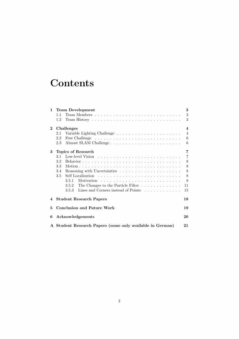
Figure 2.1: Two Color Tables for Variable Lighting Challenge
Algorithm for the variable lighting challenge using color table switching:
1. Load ”standard color table”.
2. Set current state to ”bright”.
3. Create a ring buffer of given length n.
4. Declare t = 0 as an iterator over the ring buffer.
5. For the first n frames: Write the averages of the relative brightness of eachimage (calculated with the help of the image grid) to the buffer.
6. For all other frames: Get the average and the variance of all elements ofthe ring buffer
(a) If variance is too high or if time limit tl is not reached or if t < n− 1then: Wait for switching the color tables.
(b) If average is ”small” and current state is ”bright” then: Switch todark color table (and adjust camera parameters). Set state to ”dark”.Set t = 0.
(c) If average is ”high” and current state is ”dark” then: Switch tostandard color table (and adjust camera parameters). Set state to”bright” Set t = 0.
(d) For all other configurations wait for switching the color tables.
The presented algorithm ensures that judgements for switching between thecolor tables are only made if the ring buffer contains completely new data.Although the algorithm is quite simple, we expected some difficulties. As thepresented procedure is threshold-based, the main problems occur in findingproper values for the thresholds:
• Average brightness threshold within the ring buffer
• Threshold for the variance within the ring buffer
5
• Size n of the ring buffer
• Time limit tl for staying in one state (should be greater than n − 1)
What we did, is to let the robot measure and log the percepted brightnessfor every frame over a long period of time while the robot was playing soccer.This was separately done for normal and dark environmental lighting settings.We did some statistical analysis on the recorded data to extract the minimalsize n of the ring buffer that leads to a stable threshold decision about theenvironmental lighting. If n is very low, we set an additional time limit tl = 30,which means that the robot is only allowed to switch the color table at mostonce a second. This leads to more stable results, as our prior knowledge tells usthat lightning conditions do not change every second. If the difference betweenthe lightning conditions is small, it is hard to find a threshold to divide them. Inthat case, we can additionally use the variance inside the ring buffer to achievemore stable results. The presented algorithm shows a very effective way forthe robot to detect changes in the environmental lighting. During tests in ourlaboratory it was possible for the robots to play soccer even if the very brightspotlights were switched off during the game. We also plan to integrate thislow-level computer vision algorithm as one of the parts of our vision pipelinefor feature extraction.
2.2 Free Challenge
In the free challenge, the Hamburg Dog Bots presented a commentator-system.The original intention was to build a totally autonomous system that couldrecognize certain game situations (e.g.: goals, fouls, ball out, etc.) and commentthese situations. The purpose of the commentator-system could be to replacethe human referees with Aibo robots, since players and referees are usually of thesame kind. The commentator-system would also add a special feature to publicpresentations. Because of problems with opponent recognition (which in thecase of the commentator-system would be the team recognition) and difficultieswith accuracy of the line and ball recognition we had to show a prototypeversion at the world championship 2005 in Osaka. This prototype could read themessages from the game controller for both teams and give comments accordingto the messages. The outer appearance was largely hindered by the poor qualityof the Aibo robot speakers in combination with the poor microphone at thecompetition site. This caused the comments to be mostly not understandable.
2.3 Almost SLAM Challenge
For the Almost SLAM Challenge the Hamburg Dog Bots used the self local-ization of the Hamburg Dog Bots soccer code augmented with a configurationsolver. The self locator relied on lines, corners and combinations of lines andcorners to determine the position of the Robot.
6

Chapter 3
Topics of Research
3.1 Low-level Vision
The key aspect of the low-level vision group activity is the real-time featureextraction based on the camera images of the (ERS-7 Aibo) robot. As thisfeature extraction is needed for the robot to act properly in the soccer environ-ment it has to be performed within one perception action cycle, which leads tohard time constraints. One of the main goals of the low-level vision group isto achieve a robust enemy robot localization based on the camera image. Toachieve this, a fast region-growing algorithm is executed. The seed points forthis region growing are determined by a fast scan line based algorithm. Af-ter the regions are calculated, some low level vision features are extracted, e.g.the circumscribing contour, bounding box and moments. These features arestored and then used by the high-level vision group to generate appropriate en-emy robot percepts. Another goal is the automatic robust color segmentationand the real-time adaptation to dynamic lighting conditions. By now, the lowlevel vision is almost completely based on hardware color segmented images.The quality of the segmentation is critical for all following computational tasks.Segmentation tables made by humans require a lot of time, accuracy and skill.Our goal is to automatically obtain the color tables with less or even withouthuman interaction. Another fact is that changes in the lighting conditions havegreat impact on the correctness of the color table. So, we research for methodsto automatically adjust the color table to lighting changes.
Looking back at the hard real time constraints the low level vision has tofulfill, we are working on methods to extract details from detected features thatcannot be computed in real-time using a pipeline for detail extraction. Someobjects like landmarks are not very often seen by the robots but contain valuableinformation. The real-time feature detection cannot analyze every detail ofthe features. By analyzing the regions of interest over a series of perceptionaction cycles, maximum feature extraction is possible without slowing down theperception action cycles frequency.
7
3.2 Behavior
Another group of students is working on high-level behavior. At the GermanOpen 2005 the behavior module of the German Team Code 2004 was used.This module was programmed using the XABSL language developed by theHumboldt University of Berlin, which is based on XML. In XABSL, agents aredescribed by a hierarchy of agents (”options”), in which the next decision ismade by traversing a state machine. It turned out that the static nature of thestate machines made it difficult to add new behavior strategies on the fly.
3.3 Motion
The removal of the surrounding walls made a re-engineering of some kicks nec-essary. Additionally a group of students developed new successful kicks.
3.4 Reasoning with Uncertainties
Many variables in the RoboCup domains world state are, in different aspects,uncertain. We are researching ways to exploit uncertain information, to min-imize uncertainties and maximize information gathering in the areas of self-localization and sensor-control. We have achieved useful progress by augment-ing the world state with uncertainties. The use of uncertain - previously ignored- variables have resulted in an improved self-localization as demonstrated in theVariable Lighting Challenge during the German Open 2005. We are currentlyresearching means to use the uncertainties for sensor-control and maximizinginformation-gathering depending on the current task of the robot. Our researchis focused on mathematical models, rather than machine learning.
3.5 Self Localization
The self localization of the Hamburg Dog Bots is a modified version of the orig-inal German Team code 2004 self localization. Major changes are the introduc-tion of uncertainty values for all landmarks, and the removal of the points-tablein favor of lines and corners.
3.5.1 Motivation
After the changes to the field and the positions of the landmarks, we discoveredthat we had a serious problem with the self localization of the robots.
Analysis of the Self localization from the viewpoint of general robotics
The self localization of the Hamburg Dog Bots is an absolute localization on aknown map using fixed landmarks on known positions. The advantages of thiskind of localizations are:
• The positions of all landmarks are known.
8
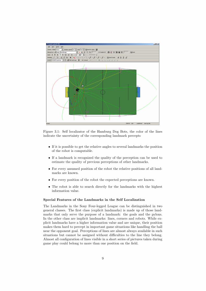
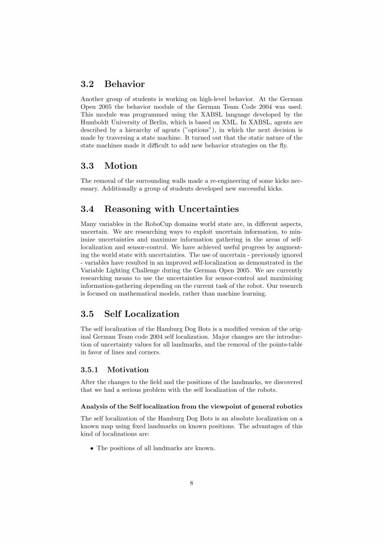
Figure 3.1: Self localizator of the Hamburg Dog Bots, the color of the linesindicate the uncertainty of the corresponding landmark percepts
• If it is possible to get the relative angles to several landmarks the positionof the robot is computable.
• If a landmark is recognized the quality of the perception can be used toestimate the quality of previous perceptions of other landmarks.
• For every assumed position of the robot the relative positions of all land-marks are known.
• For every position of the robot the expected perceptions are known.
• The robot is able to search directly for the landmarks with the highestinformation value.
Special Features of the Landmarks in the Self Localization
The Landmarks in the Sony Four-legged League can be distinguished in twogeneral classes. The first class (explicit landmarks) is made up of those land-marks that only serve the purpose of a landmark: the goals and the pylons.In the other class are implicit landmarks: lines, corners and robots. While ex-plicit landmarks have a higher information value and are unique, their positionmakes them hard to percept in important game situations like handling the ballnear the opponent goal. Perceptions of lines are almost always available in suchsituations but cannot be assigned without difficulties to the line they belong.Almost all configuration of lines visible in a short series of pictures taken duringgame play could belong to more than one position on the field.
9
The Pylons There are four pylons on the map. They have a unique colorpattern and are cylindric which makes them easy to identify. However they don’thave an orientation other than up down which can be used for the localization.
Figure 3.2: A Pylon
The pylons are tall and the distance between the robot and the pylons canbe calculated thanks to the color patterns and the height of the pylons whichare higher than the robots camera. The uncertainty of a pylon perception canbe estimated by the number of recognized pixel belonging to the landmark. Thebottoms of the pylons are also usable as landmarks.
The Goals The Goals are 20cm tall and 60cm wide. There is one yellowand one blue goal. Their size and color makes them excellent landmarks. Thedistance to a goal can be estimated easily, as long as the goal is not too close tothe robot.
The Lines and Corners of the Field Border The lines and corners of thefield border can be used to estimate the position of the robot, but only from ashort distance. They are very useful for estimating the rotation of the robot.
The Circle in the Middle Field The circle on the middle field is also aunique landmark and as such very useful for the localization of the robot.
The Lines and Corners in the Penalty Area The lines of the penalty areaare well suited as a landmark particularly for the goalie. The goalie is almostalways able to recognize the corners of the penalty area.
10
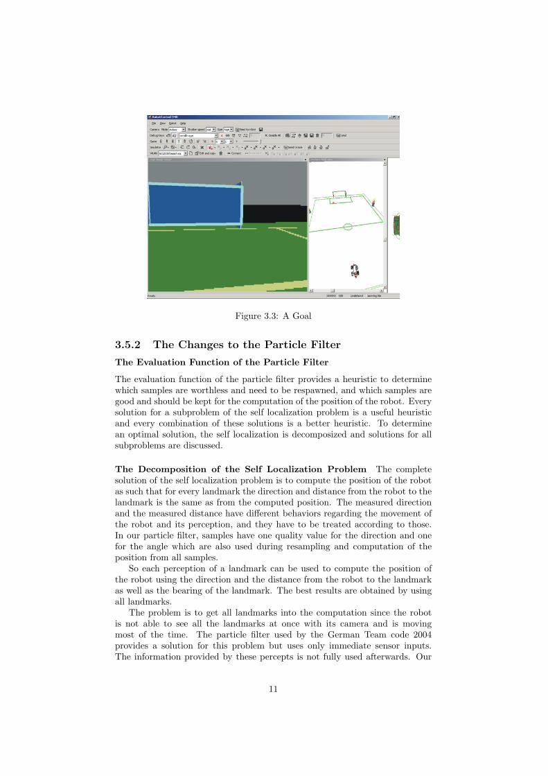
Figure 3.3: A Goal
3.5.2 The Changes to the Particle Filter
The Evaluation Function of the Particle Filter
The evaluation function of the particle filter provides a heuristic to determinewhich samples are worthless and need to be respawned, and which samples aregood and should be kept for the computation of the position of the robot. Everysolution for a subproblem of the self localization problem is a useful heuristicand every combination of these solutions is a better heuristic. To determinean optimal solution, the self localization is decomposized and solutions for allsubproblems are discussed.
The Decomposition of the Self Localization Problem The completesolution of the self localization problem is to compute the position of the robotas such that for every landmark the direction and distance from the robot to thelandmark is the same as from the computed position. The measured directionand the measured distance have different behaviors regarding the movement ofthe robot and its perception, and they have to be treated according to those.In our particle filter, samples have one quality value for the direction and onefor the angle which are also used during resampling and computation of theposition from all samples.
So each perception of a landmark can be used to compute the position ofthe robot using the direction and the distance from the robot to the landmarkas well as the bearing of the landmark. The best results are obtained by usingall landmarks.
The problem is to get all landmarks into the computation since the robotis not able to see all the landmarks at once with its camera and is movingmost of the time. The particle filter used by the German Team code 2004provides a solution for this problem but uses only immediate sensor inputs.The information provided by these percepts is not fully used afterwards. Our
11
approach is to keep this information by tracking the positions of the perceptionsrelative to the robot. The positions are moved according to the odometry justlike the samples of the particle filter. Unfortunately our odometric sensor inputsare not of good quality. To deal with this problem we introduced two valuesrepresenting the uncertainty of the distance and the direction to a landmarkperception. Each landmark is augmented with these values that are also usefulfor sensor control. As long as the robot is just rotating (x) or translating oneuncertainty value, it is almost unaffected, a fact that is very useful in some gamesituations.
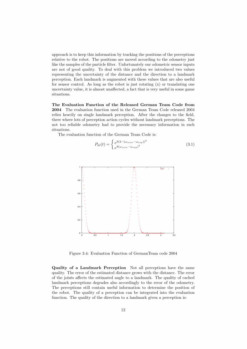
The Evaluation Function of the Released German Team Code from2004 The evaluation function used in the German Team Code released 2004relies heavily on single landmark perception. After the changes to the field,there where lots of perception action cycles without landmark perceptions. Thenot too reliable odometry had to provide the necessary information in suchsituations.
The evaluation function of the German Team Code is:
Phl(t) =
{
eδ(2−(ωseen−ωexp))2
eδ(ωseen−ωexp)2(3.1)
0
0.2
0.4
0.6
0.8
1
0 0.5 1 1.5 2 2.5 3 3.5
"GT"
Figure 3.4: Evaluation Function of GermanTeam code 2004
Quality of a Landmark Perception Not all perceptions have the samequality. The error of the estimated distance grows with the distance. The errorof the joints affects the estimated angle to a landmark. The quality of cachedlandmark perceptions degrades also accordingly to the error of the odometry.The perceptions still contain useful information to determine the position ofthe robot. The quality of a perception can be integrated into the evaluationfunction. The quality of the direction to a landmark given a perception is:
12
bval =2π − 2ceorl
2π(3.2)
where ceorlis the cumulative estimated odometric error since the last sensor
reading from the landmark l.The quality of the estimated distance to a landmark is:
bvdl =dl · (
bvfdl+bvfol
2 ) − 2ceotl
dl
(3.3)
where bvddl is the estimated quality of the distance to the landmark basedon the distance from the robot to the landmark l. bvfol is the estimated qualitybased on computation of the image processor. ceotl
is the cumulative estimatederror of the odometry regarding the translation since the last sensor reading ofthe landmark l. dl is a factor to norm the bva to [1, 0].
Adding the Quality of Percepts to the Evaluation Model The integra-tion of the quality or uncertainty of the percepts into the evaluation model isafter these considerations an easy task. Each Landmark has an ”belief value”for the direction (bva) and the distance (bvd) computed from the sensor read-ings. The bvd and bva degrade when the robot moves. They are set every timethe robot recognizes a landmark. The change of the quality of a sample in theparticle filter given a landmark percept converges to the original quality of thesample as the ”belief values” degrade.
The New Evaluation Function using Uncertainty The evaluation func-tion based on the distance between robot and landmark takes the quality of themeasured distance into account resulting in a more precise computation of therobot position. The landmark percepts in the German Team code 2004 providedbasic algorithms that where appropriate to set the initial quality value of thedistance measurement.
The maximum probability or quality of a distance measurement given alandmark percept is 1, in this case the measured distance is equal to the realdistance. A simple measurement for the probability of a sample is 1 − nali,where nali is the normalized difference of the distance between sample i andlandmark l and the measured distance to the landmark l.
The new function for the evaluation of samples based on the distance betweensample and landmark is:
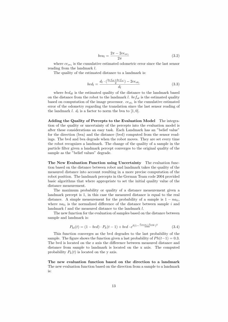
Phl(t) = (1 − bvd) · Ph(t − 1) + bvd · eδ(1−dseen−dexp
1000)2 (3.4)
This function converges as the bvd degrades to the last probability of thesample. The figure shows the function given a last probability of Ph(t−1) = 0.3.The bvd is located on the z axis the difference between measured distance anddistance from sample to landmark is located on the x axis. The computedprobability Ph(t) is located on the y axis.
The new evaluation function based on the direction to a landmarkThe new evaluation function based on the direction from a sample to a landmarkis:
13
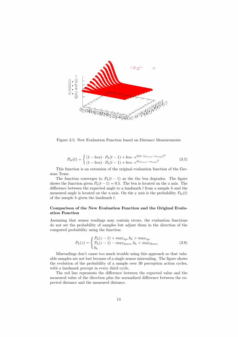
Figure 3.5: New Evaluation Function based on Distance Measurements
Phl(t) =
{
(1 − bva) · Ph(t − 1) + bva · eδ(2−(ωseen−ωexp))2
(1 − bva) · Ph(t − 1) + bva · eδ(ωseen−ωexp)2(3.5)
This function is an extension of the original evaluation function of the Ger-man Team.
The function converges to Ph(t − 1) as the the bva degrades. The figureshows the function given Ph(t− 1) = 0.5. The bva is located on the z axis. Thedifference between the expected angle to a landmark l from a sample h and themeasured angle is located on the x-axis. On the y axis is the probability Phl(t)of the sample h given the landmark l.
Comparison of the New Evaluation Function and the Original Evalu-ation Function
Assuming that sensor readings may contain errors, the evaluation functionsdo not set the probability of samples but adjust them in the direction of thecomputed probability using the function:
Ph(z) =
{
Ph(z − 1) + maxup, bh > maxup
Ph(z − 1) − maxdown, bh < maxdown
bh
(3.6)
Misreadings don’t cause too much trouble using this approach so that valu-able samples are not lost because of a single sensor misreading. The figure showsthe evolution of the probability of a sample over 30 perception action cycles,with a landmark percept in every third cycle.
The red line represents the difference between the expected value and themeasured value of the direction plus the normalized difference between the ex-pected distance and the measured distance.
14
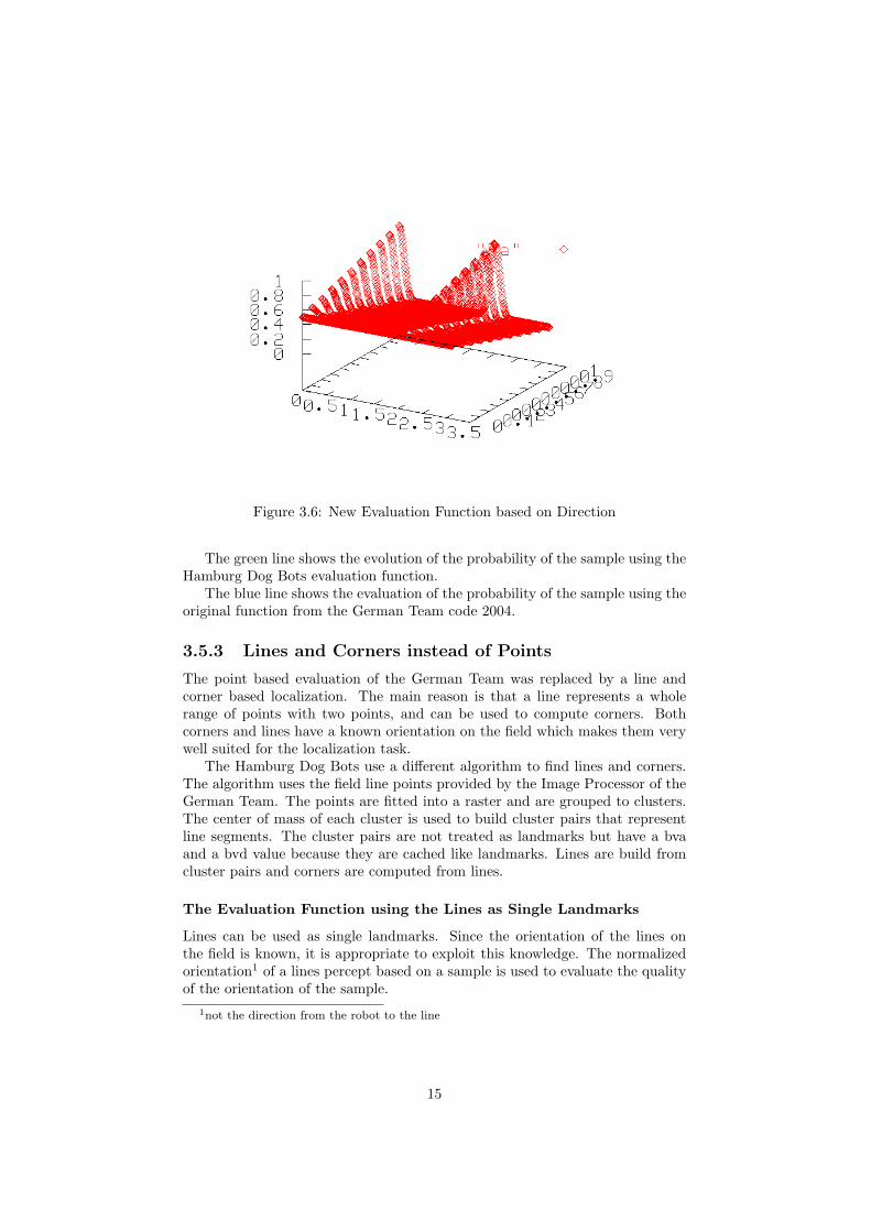
Figure 3.6: New Evaluation Function based on Direction
The green line shows the evolution of the probability of the sample using theHamburg Dog Bots evaluation function.
The blue line shows the evaluation of the probability of the sample using theoriginal function from the German Team code 2004.
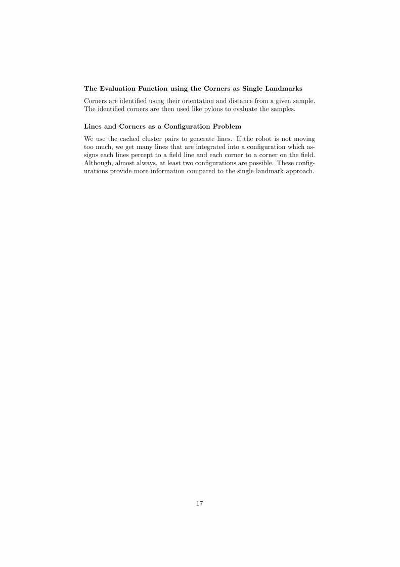
3.5.3 Lines and Corners instead of Points
The point based evaluation of the German Team was replaced by a line andcorner based localization. The main reason is that a line represents a wholerange of points with two points, and can be used to compute corners. Bothcorners and lines have a known orientation on the field which makes them verywell suited for the localization task.
The Hamburg Dog Bots use a different algorithm to find lines and corners.The algorithm uses the field line points provided by the Image Processor of theGerman Team. The points are fitted into a raster and are grouped to clusters.The center of mass of each cluster is used to build cluster pairs that representline segments. The cluster pairs are not treated as landmarks but have a bvaand a bvd value because they are cached like landmarks. Lines are build fromcluster pairs and corners are computed from lines.
The Evaluation Function using the Lines as Single Landmarks
Lines can be used as single landmarks. Since the orientation of the lines onthe field is known, it is appropriate to exploit this knowledge. The normalizedorientation1 of a lines percept based on a sample is used to evaluate the qualityof the orientation of the sample.
1not the direction from the robot to the line
15
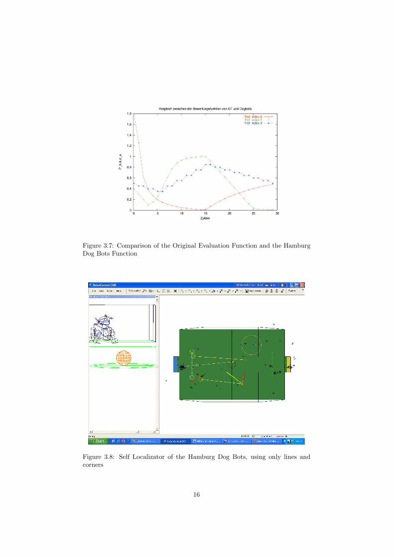
Figure 3.7: Comparison of the Original Evaluation Function and the HamburgDog Bots Function
Figure 3.8: Self Localizator of the Hamburg Dog Bots, using only lines andcorners
16
The Evaluation Function using the Corners as Single Landmarks
Corners are identified using their orientation and distance from a given sample.The identified corners are then used like pylons to evaluate the samples.
Lines and Corners as a Configuration Problem
We use the cached cluster pairs to generate lines. If the robot is not movingtoo much, we get many lines that are integrated into a configuration which as-signs each lines percept to a field line and each corner to a corner on the field.Although, almost always, at least two configurations are possible. These config-urations provide more information compared to the single landmark approach.
17
Chapter 4
Student Research Papers
During the project several project-, studies- and diploma-thesis evolved fromdifferent approaches:
• Jana Passow: Geometrieidentifikation aus den Kamerabildern mobiler au-tonomer Systeme in der Sony Fourlegged Robot League. Diplomarbeit,Fachbereich Informatik, Universitat Hamburg, June 2004.
• Peter Roßmeyer: Teamwork exemplified by the Four-Legged League inRoboCup. Studienarbeit, MIN-Fakultat/Informatik, Universitat Ham-burg, to appear in spring 2006.
• Valerij Krichevskyi: Analyse und Implementierung der ‘Variable LightingChallenge‘ der Four-Legged-Liga im RoboCup. Studienarbeit, Fachbere-ich Informatik, Universitat Hamburg, September 2005
• Malte-Nils Sorensen: Autonomes zweibeiniges Stehen von Sony Aibo Ro-botern durch Einbettung von Beschleunigungssensoren. Baccalaureatsar-beit, Fachbereich Informatik, Universitat Hamburg, January 2005.
• Jonas Reese: Lernsystem fur die Verhaltenssteuerung in der RoboCupFour Legged League. Projektarbeit, Fachbereich Informatik, UniversitatHamburg, March 2005
• Sonia Haiduc: Opponent Recognition and Localization, Part 1 and Part2. Projektarbeit, Fachbereich Informatik, Universitat Hamburg, 2005
The student research papers of 2005 are attached in the appendix of the teamreport.
18
Chapter 5
Conclusion and FutureWork
In this report, we introduced our current approaches for the Sony Four leggedleague.
Because of the issues with the behavior as mentioned in section 3.2, wedecided to substitute the XABSL based behavior module by a new module basedon another agent description language, an easy to understand programminglanguage for defining behavior developed by the Hamburg Dog Bots team.
Our overall goal is to include more collaborative behavior in future work.By means of integrating socionic and game theory the robots should play as ateam instead of playing antagonism. Another aspect of future work relates tothe little interest of women in the Sony Four-legged League. Besides includingsocionic aspects like communication and cooperation in the behavior of thesoccer-playing robots we will develop new additional scenarios to foster interestof women in robotics.
19
Chapter 6
Acknowledgements
Our participation in the RoboCup 2005 event could not have been possible with-out the help from many persons all around the world. The team of the HamburgDog Bots is grateful to all friends, previous members, and other supporters ofthe team including Klaus-Dieter Florstedt and other technical support and ad-ministrative staff of the MIN-Fakultat/Informatik of the Universitat Hamburg.We thank the organizers of RoboCup 2005 for travel support and the greatorganization of the World Cup. We greatfully acknowledge the support andcooperation of the ”Behorde fur Wirtschaft und Arbeit” in Hamburg, the De-partment ”Forschung und Wissenschaftsforderung” of Universitat Hamburg, theGoethe-Institut of Osaka, the International Relations Department of the Cityof Osaka and the employees of the Truck Terminal of Osaka, who made thejourney to Osaka possible. Further, we would like to thank the German Teamfor providing their source code in 2004.
Our publications as well as videos and pictures are available on the HamburgDog Bots’ webpage: http://www.hamburgdogbots.de.
20
Appendix A
Student Research Papers(some only available inGerman)
21
Universität der Freien und Hansestadt Hamburg Fachbereich Informatik
Arbeitsbereich Technische Informatiksysteme
Studienarbeit
Analyse und Implementierung der
„Variable Lighting Challenge”
der Fourlegged-Liga im RoboCup
Valerij Krichevskyi Matr. Nr. 4865042
9. September 2005
betreut durch Prof. Dr.-Ing. Dietmar P. F. Möller,
Dipl.-Inform. Birgit Koch

Seite 1
Seite 2
Inhaltsverzeichnis
1. Abstract .................................................................................................. 4 2. Einleitung ............................................................................................... 6 3. Grundbegriffe ......................................................................................... 8 4. Aufgabenstellung ................................................................................. 10 5. Farbmodelle.......................................................................................... 14
5.1. Das RGB-Modell........................................................................... 14 5.2. Das YUV-Modell .......................................................................... 14 5.3. Das HSV-Modell........................................................................... 17 5.4. Das TSL-Modell............................................................................ 18
6. Analyse................................................................................................. 21 6.1. Testaufnahmen .............................................................................. 21 6.2. Bildanalyse .................................................................................... 21
7. Farbklassifikationsmodule ................................................................... 30 7.1. ColorTable32 und ColorTable64 .................................................. 30 7.2. ColorTableTSL.............................................................................. 31 7.3. HSIColorTable .............................................................................. 32
8. Dynamische versus statische Farbklassifikation. ................................. 34 9. Analyse, Implementation und Einbindung in den Hamburg Dog Bots-Code 35 10. Ausblick: Automatisierung der Farberkennung ................................... 38 11. Fazit ...................................................................................................... 39 12. Literaturliste ......................................................................................... 40 13. Anhang ................................................................................................. 42
13.1. What is RoboCup? ........................................................................ 42 13.2. The Variable Lighting Challenge.................................................. 44 13.3. Sony Four Legged Robot Football League Rule Book ................. 46
14. Eidesstattliche Erklärung...................................................................... 67

Seite 3

Seite 4
1. Abstract
Bei RoboCup-Spielen der Fourlegged-Liga werden Sony Aibo Roboter eingesetzt, deren Kamerabildqualität sehr stark von den Lichtverhältnissen abhängt. Je nach Beleuchtung können die von der Kamera erfassten Farben sich so von der Realität unterscheiden, dass sie als andere Farben erkannt werden. Die erkannten Farben stellen einen Grundbaustein der weiteren Bildbearbeitung dar. Damit die Bildbearbeitung zuverlässig funktioniert, haben alle RoboCup-Spiele bis zur heutigen Zeit bei fast konstanten Lichtverhältnissen stattgefunden. Da nicht immer konstante Lichtverhältnisse gegeben sind, und die Roboter auch bei realen Bedingungen spielen können sollen, müssen die Roboter in der Lage sein, trotz sich ändernder Lichtverhältnisse Farben bestimmten Farbklassen zuzuordnen.
In der vorliegenden Arbeit wird untersucht, wie die Farben fehlerfrei im Echtzeit-Betrieb identifiziert werden können. Im Weiteren wird analysiert, welche Verfahren bei anderen RoboCup-Teams eingesetzt werden. Zum Schluss wird ein Ausblick auf eine Automatisierung der Farberkennung gegeben.

Seite 5
Seite 6
2. Einleitung
Robotervision
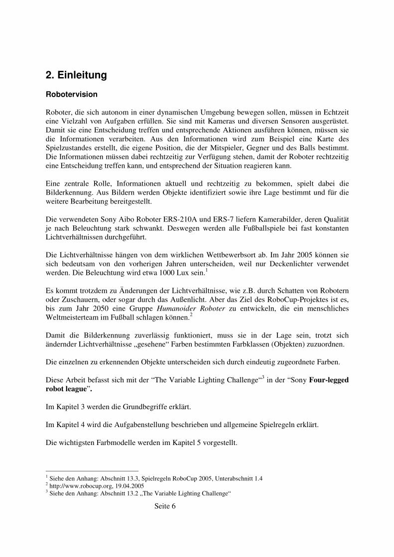
Roboter, die sich autonom in einer dynamischen Umgebung bewegen sollen, müssen in Echtzeit eine Vielzahl von Aufgaben erfüllen. Sie sind mit Kameras und diversen Sensoren ausgerüstet. Damit sie eine Entscheidung treffen und entsprechende Aktionen ausführen können, müssen sie die Informationen verarbeiten. Aus den Informationen wird zum Beispiel eine Karte des Spielzustandes erstellt, die eigene Position, die der Mitspieler, Gegner und des Balls bestimmt. Die Informationen müssen dabei rechtzeitig zur Verfügung stehen, damit der Roboter rechtzeitig eine Entscheidung treffen kann, und entsprechend der Situation reagieren kann.
Eine zentrale Rolle, Informationen aktuell und rechtzeitig zu bekommen, spielt dabei die Bilderkennung. Aus Bildern werden Objekte identifiziert sowie ihre Lage bestimmt und für die weitere Bearbeitung bereitgestellt.
Die verwendeten Sony Aibo Roboter ERS-210A und ERS-7 liefern Kamerabilder, deren Qualität je nach Beleuchtung stark schwankt. Deswegen werden alle Fußballspiele bei fast konstanten Lichtverhältnissen durchgeführt.
Die Lichtverhältnisse hängen von dem wirklichen Wettbewerbsort ab. Im Jahr 2005 können sie sich bedeutsam von den vorherigen Jahren unterscheiden, weil nur Deckenlichter verwendet werden. Die Beleuchtung wird etwa 1000 Lux sein.1
Es kommt trotzdem zu Änderungen der Lichtverhältnisse, wie z.B. durch Schatten von Robotern oder Zuschauern, oder sogar durch das Außenlicht. Aber das Ziel des RoboCup-Projektes ist es, bis zum Jahr 2050 eine Gruppe Humanoider Roboter zu entwickeln, die ein menschliches Weltmeisterteam im Fußball schlagen können.2
Damit die Bilderkennung zuverlässig funktioniert, muss sie in der Lage sein, trotzt sich ändernder Lichtverhältnisse „gesehene“ Farben bestimmten Farbklassen (Objekten) zuzuordnen.
Die einzelnen zu erkennenden Objekte unterscheiden sich durch eindeutig zugeordnete Farben.
Diese Arbeit befasst sich mit der “The Variable Lighting Challenge“3 in der “Sony Four-legged
robot league”.
Im Kapitel 3 werden die Grundbegriffe erklärt.
Im Kapitel 4 wird die Aufgabenstellung beschrieben und allgemeine Spielregeln erklärt.
Die wichtigsten Farbmodelle werden im Kapitel 5 vorgestellt.
1 Siehe den Anhang: Abschnitt 13.3, Spielregeln RoboCup 2005, Unterabschnitt 1.4 2 http://www.robocup.org, 19.04.2005 3 Siehe den Anhang: Abschnitt 13.2 „The Variable Lighting Challenge“
Seite 7
Im Kapitel 6 wird eine Analyse des Farbverhalten verschiedener Objekte bei diversen Belichtungsstärken durchgeführt und anschließend verglichen.
Danach werden im Kapitel 7 vorhandene Module des GermanTeam Projektes untersucht und Vor- und Nachteile sowie Gemeinsamkeiten festgestellt.
Die Möglichkeiten dynamischer Verfahren der Farbklassifikation werden im Kapitel 8 angedeutet.
Weiter werden im Kapitel 9 eine Zusammenfassung des Kapitels 6 bis 8 vorgestellt, sowie die Analyse, die Implementation und die Einbindung in den GermanTeam-Code beschrieben.
Im Kapitel 10 wird ein Ausblick auf die Automatisierung der Farberkennung gegeben.
Eine Zusammenfassung wird im Kapitel 11 vorgestellt.
Seite 8
3. Grundbegriffe
Was ist unter dem Begriff RoboCup zu verstehen?4
Der Begriff RoboCup bezeichnet eine internationale Forschungs- und Ausbildungsinitiative, deren Ziel es ist, die Künstliche Intelligenz und die Robotertechnik-Forschung zu fördern und eine ganze Reihe von Standardproblemen zu untersuchen.
RoboCup - Fußball5
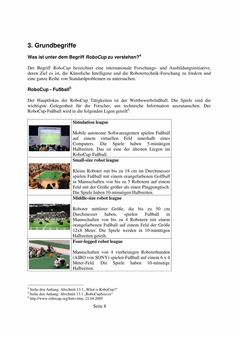
Der Hauptfokus der RoboCup Tätigkeiten ist der Wettbewerbsfußball. Die Spiele sind die wichtigste Gelegenheit für die Forscher, um technische Information auszutauschen. Der RoboCup-Fußball wird in die folgenden Ligen geteilt6:
Simulation league
Mobile autonome Softwareagenten spielen Fußball auf einem virtuellen Feld innerhalb eines Computers. Die Spiele haben 5-minütigen Halbzeiten. Das ist eine der ältesten Liegen im RoboCup-Fußball.
Small-size robot league
Kleine Roboter mit bis zu 18 cm im Durchmesser spielen Fußball mit einem orangefarbenen Golfball in Mannschaften von bis zu 5 Robotern auf einem Feld mit der Größe größer als einen Pingpongtisch. Die Spiele haben 10-minutigen Halbzeiten.
Middle-size robot league
Roboter mittlerer Größe, die bis zu 50 cm Durchmesser haben, spielen Fußball in Mannschaften von bis zu 4 Robotern mit einem orangefarbenen Fußball auf einem Feld der Größe 12x8 Meter. Die Spiele werden in 10-minütigen Halbzeiten geteilt.
Four-legged robot league
Mannschaften von 4 vierbeinigen Roboterhunden (AIBO von SONY) spielen Fußball auf einem 6 x 4 Meter-Feld. Die Spiele haben 10-minutige Halbzeiten.
4 Siehe den Anhang: Abschnitt 13.1 „What is RoboCup?“ 5 Siehe den Anhang: Abschnitt 13.1 „RoboCupSoccer“ 6 http://www.robocup.org/Intro.htm, 21.04.2005
Seite 9
Humanoid league
Diese Liga wurde 2002 eingeführt. Zweifüßige autonome humanoide Roboter spielen im "Elfmeterschießen", "1 gegen 1" und "2 gegen 2". "Freistil" Wettbewerbe werden ebenso erwartet.
RoboCup-Challenges
Zusätzlich zu dem RoboCup-Fußball werden auch Challenges organisiert. Eine Challenge ist eine Herausforderung, um Mannschaften zu ermuntern, ein bestehendes Hauptproblem im RoboCup zu untersuchen und zu lösen.
GermanTeam Projekt
Das GermanTeam ist eine deutsche Roboter-Fußballmannschaft, die in der Sony Four-legged
robot league an internationalen RoboCup Wettkämpfen teilnimmt. Das Projekt ist eine Zusammenarbeit von vier deutschen Universitäten: der Humboldt Universität zu Berlin, der Universität Bremen, der Technischen Universität Darmstadt, und der Universität Dortmund.7
Der von dem GermanTeam in der RoboCup-Weltmeisterschaft 2004 verwendete Quellcode ist für das Download verfügbar. Das Archiv enthält die notwendige Software, um Roboter-Fußballspiele durchzuführen. Die Komponenten sind sowohl als C++ Quellcode als auch für Windows (XP/2000) kompilierte Module (Programme) im Archiv enthalten.8
Hamburg Dog Bots9
Hamburg Dog Bots ist das Team der Universität Hamburg, das in der Sony Four-legged robot
league an internationalen RoboCup Wettkämpfen teilnimmt. Das Team hat 2004 den Quellcode des GermanTeams übernommen und entwickelt seitdem darauf aufbauend eigenständigen Quellcode.
7 http://www.germanteam.org, 19.04.2005 8 http://www.germanteam.org, 19.04.2005 9 http://www.informatik.uni-hamburg.de/TIS/index.php?content=robocup/index.htm, 15.04.2005
Seite 10
4. Aufgabenstellung
Die “Variable Lighting Challenge“10
Diese Challenge beabsichtigt Mannschaften zu ermuntern, die Robustheit ihrer Vision zu Beleuchtungsänderungen zu verbessern. Sie beruht auf dem Penalty Shootout. Die Mannschaft, die die Herausforderung versucht, stellt einen einzelnen Roboter (mit einer blauen Uniform) auf das Feld. Dieser Roboter muss so viele Treffer erzielen, wie er in das gelbe Tor in drei Minuten kann. Die Mannschaft, die die meisten Treffer hat, gewinnt die Challenge. Wenn zwei Mannschaften dieselbe Zahl von Treffer haben, dann gewinnt die Mannschaft mit der niedrigsten durchschnittlichen Trefferzeit (Hinweis: das ist dasselbe wie die Auswahl einer Mannschaft, die ihr letztes Tor am frühsten schoss). Wenn keine Mannschaft Treffer hat, dann gewinnt die Mannschaft, die mit dem Ball am Ende ihrer Zeit am nächsten zum Tor war.
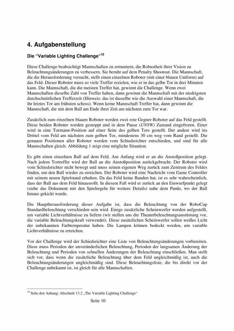
Zusätzlich zum einzelnen blauen Roboter werden zwei rote Gegner-Roboter auf das Feld gestellt. Diese beiden Roboter werden gestoppt und in dem Pause (UNSW) Zustand eingefroren. Einer wird in eine Tormann-Position auf einer Seite des gelben Tors gestellt. Der andere wird ins Drittel vom Feld am nächsten zum gelben Tor, mindestens 30 cm weg vom Rand gestellt. Die genauen Positionen aller Roboter werden vom Schiedsrichter entschieden, und sind für alle Mannschaften gleich. Abbildung 1 zeigt eine mögliche Situation.
Es gibt einen einzelnen Ball auf dem Feld. Am Anfang wird er an die Anstoßposition gelegt. Nach jedem Tortreffer wird der Ball an die Anstoßposition zurückgebracht. Der Roboter wird vom Schiedsrichter nicht bewegt und muss seinen eigenen Weg zurück zum Zentrum des Feldes finden, um den Ball wieder zu erreichen. Der Roboter wird eine Nachricht vom Game Controller mit seinem neuen Spielstand erhalten. Da das Feld keine Banden hat, ist es sehr wahrscheinlich, dass der Ball aus dem Feld hinausrollt. In diesem Fall wird er zurück an den Einwurfpunkt gelegt (siehe das Dokument mit den Spielregeln für weitere Details) nahe dem Punkt, wo der Ball hinaus gekickt wurde.
Die Hauptherausforderung dieser Aufgabe ist, dass die Beleuchtung von der RoboCup Standardbeleuchtung verschieden sein wird. Einige zusätzliche Scheinwerfer werden aufgestellt, um variable Lichtverhältnisse zu liefern (wir stellen uns die Theaterbeleuchtungsausrüstung vor, die variable Beleuchtungskraft verwendet). Diese zusätzlichen Scheinwerfer sollen weißes Licht der unbekannten Farbtemperatur haben. Die Lampen können bedeckt werden, um variable Lichtverhältnisse zu erreichen.
Vor der Challenge wird der Schiedsrichter eine Liste von Beleuchtungsänderungen vorbereiten. Diese muss Perioden der unveränderlichen Beleuchtung, Perioden der langsamen Änderung der Beleuchtung und Perioden von schnellen Änderungen der Beleuchtung einschließen. Man stellt sich vor, dass wenn die zusätzliche Beleuchtung über dem Feld ungleichmäßig ist, auch die Beleuchtungsänderungen ungleichmäßig sind. Diese Beleuchtungsliste, die bis direkt vor der Challenge unbekannt ist, ist gleich für alle Mannschaften.
10 Sehe den Anhang: Abschnitt 13.2 „The Variable Lighting Challenge“
Seite 11
Wenn sonst nichts angegeben ist, gelten normale Penalty Shootout-Regeln. Es gibt keine Strafe für den Angriff auf einen Gegner-Roboter. Es ist nicht erlaubt, einem Roboter zu helfen, den Angriff zu beenden.
Abbildung 1 Ein Beispiel einer Aufstellung von Robotergegnern für die „Variable Lighting Challenge“
Allgemeine Bestimmungen und Regeln11
Die Sony Fourlegged Robot League ist ein Teilprojekt des RoboCup, in dem Aibo-Roboterhunde vom Typ ERS-210, ERS-210A oder ERS-7 von SONY verwendet werden. Diese sind entweder schwarz oder weiß. An der Hardware der Roboter sind keine Veränderungen erlaubt. Es dürfen weder zusätzliche Sensoren noch Speichererweiterungen oder leistungsfähigere Prozessoren eingebaut werden. Es ist ebenfalls nicht erlaubt, Berechnungen auf einen externen Rechner auszulagern. Ein WLAN wird über einen Rechner der Organisatoren bereitgestellt. Über diesen werden lediglich die Nachrichten zwischen den Robotern weitergeleitet. Berechnungen auf diesen Rechner auszulagern, ist nicht gestattet.
In der Tabelle 1 sind festgelegte Farben und entsprechende Objekte dargestellt12.
11 Siehe Anhang, Abschnitt 13.3, Spielregeln RoboCup 2005 12 Siehe Anhang, Abschnitt 13.3, Spielregeln RoboCup 2005
Seite 12
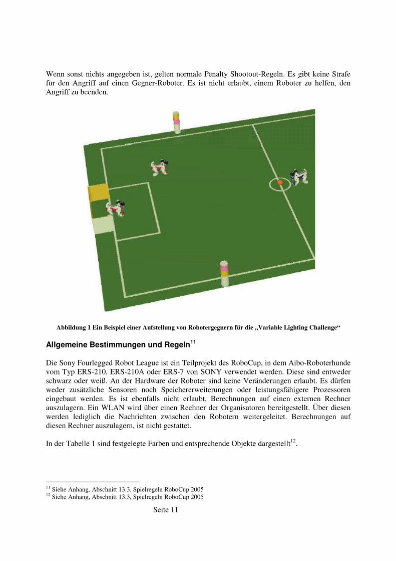
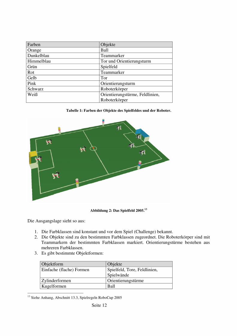
Farben Objekte Orange Ball Dunkelblau Teammarker Himmelblau Tor und Orientierungsturm Grün Spielfeld Rot Teammarker Gelb Tor Pink Orientierungsturm Schwarz Roboterkörper Weiß Orientierungstürme, Feldlinien,
Roboterkörper
Tabelle 1: Farben der Objekte des Spielfeldes und der Roboter.
Abbildung 2: Das Spielfeld 2005.13
Die Ausgangslage sieht so aus:
1. Die Farbklassen sind konstant und vor dem Spiel (Challenge) bekannt. 2. Die Objekte sind zu den bestimmten Farbklassen zugeordnet. Die Roboterkörper sind mit
Teammarkern der bestimmten Farbklassen markiert. Orientierungstürme bestehen aus mehreren Farbklassen.
3. Es gibt bestimmte Objektformen:
Objektform Objekte Einfache (flache) Formen Spielfeld, Tore, Feldlinien,
Spielwände Zylinderformen Orientierungstürme Kugelformen Ball
13 Siehe Anhang, Abschnitt 13.3, Spielregeln RoboCup 2005
Seite 13
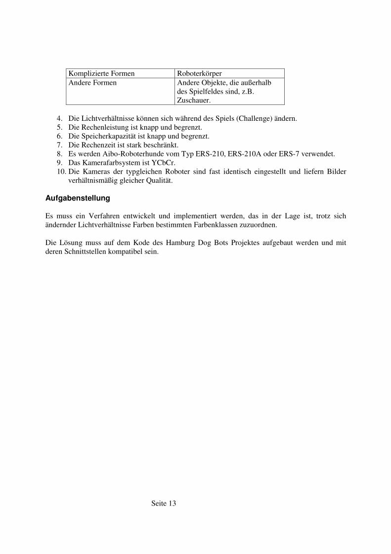
Komplizierte Formen Roboterkörper Andere Formen Andere Objekte, die außerhalb
des Spielfeldes sind, z.B. Zuschauer.
4. Die Lichtverhältnisse können sich während des Spiels (Challenge) ändern. 5. Die Rechenleistung ist knapp und begrenzt. 6. Die Speicherkapazität ist knapp und begrenzt. 7. Die Rechenzeit ist stark beschränkt. 8. Es werden Aibo-Roboterhunde vom Typ ERS-210, ERS-210A oder ERS-7 verwendet. 9. Das Kamerafarbsystem ist YCbCr. 10. Die Kameras der typgleichen Roboter sind fast identisch eingestellt und liefern Bilder
verhältnismäßig gleicher Qualität.
Aufgabenstellung
Es muss ein Verfahren entwickelt und implementiert werden, das in der Lage ist, trotz sich ändernder Lichtverhältnisse Farben bestimmten Farbenklassen zuzuordnen.
Die Lösung muss auf dem Kode des Hamburg Dog Bots Projektes aufgebaut werden und mit deren Schnittstellen kompatibel sein.
Seite 14
5. Farbmodelle
Farbmodelle dienen der formalen Beschreibung von Farben. Eine Farbe lässt sich durch Angabe von Farbton, Sättigung und Helligkeit eindeutig beschreiben. Diese Parameter werden zum Beispiel im HSV-Modell (Kapitel 5.3) direkt verwendet. Für verschiedene technische Anwendungen wurden verschiedene Farbmodelle entwickelt, die für die jeweils zugeordneten Aufgabengebiete vorteilhafte Eigenschaften besitzen.
5.1. Das RGB-Modell14
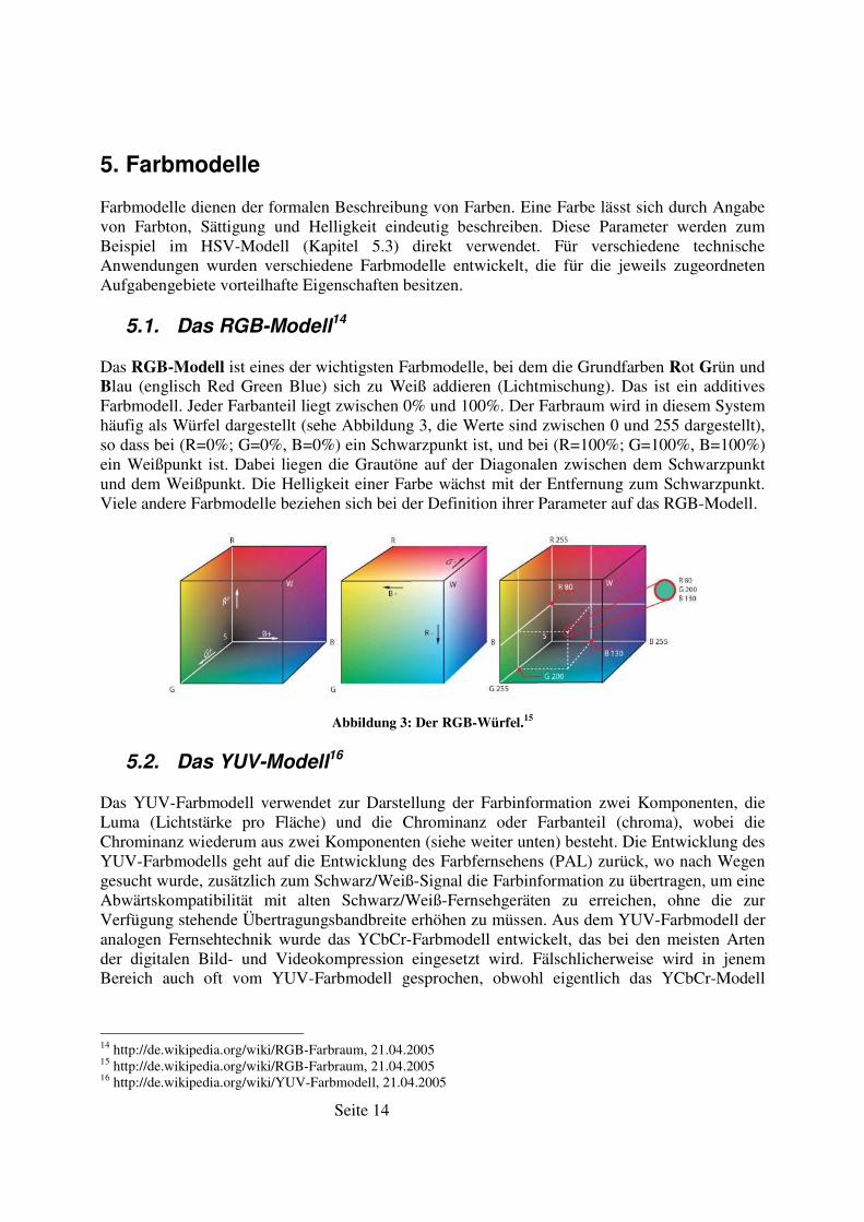
Das RGB-Modell ist eines der wichtigsten Farbmodelle, bei dem die Grundfarben Rot Grün und Blau (englisch Red Green Blue) sich zu Weiß addieren (Lichtmischung). Das ist ein additives Farbmodell. Jeder Farbanteil liegt zwischen 0% und 100%. Der Farbraum wird in diesem System häufig als Würfel dargestellt (sehe Abbildung 3, die Werte sind zwischen 0 und 255 dargestellt), so dass bei (R=0%; G=0%, B=0%) ein Schwarzpunkt ist, und bei (R=100%; G=100%, B=100%) ein Weißpunkt ist. Dabei liegen die Grautöne auf der Diagonalen zwischen dem Schwarzpunkt und dem Weißpunkt. Die Helligkeit einer Farbe wächst mit der Entfernung zum Schwarzpunkt. Viele andere Farbmodelle beziehen sich bei der Definition ihrer Parameter auf das RGB-Modell.
Abbildung 3: Der RGB-Würfel.15
5.2. Das YUV-Modell16
Das YUV-Farbmodell verwendet zur Darstellung der Farbinformation zwei Komponenten, die Luma (Lichtstärke pro Fläche) und die Chrominanz oder Farbanteil (chroma), wobei die Chrominanz wiederum aus zwei Komponenten (siehe weiter unten) besteht. Die Entwicklung des YUV-Farbmodells geht auf die Entwicklung des Farbfernsehens (PAL) zurück, wo nach Wegen gesucht wurde, zusätzlich zum Schwarz/Weiß-Signal die Farbinformation zu übertragen, um eine Abwärtskompatibilität mit alten Schwarz/Weiß-Fernsehgeräten zu erreichen, ohne die zur Verfügung stehende Übertragungsbandbreite erhöhen zu müssen. Aus dem YUV-Farbmodell der analogen Fernsehtechnik wurde das YCbCr-Farbmodell entwickelt, das bei den meisten Arten der digitalen Bild- und Videokompression eingesetzt wird. Fälschlicherweise wird in jenem Bereich auch oft vom YUV-Farbmodell gesprochen, obwohl eigentlich das YCbCr-Modell
14 http://de.wikipedia.org/wiki/RGB-Farbraum, 21.04.2005 15 http://de.wikipedia.org/wiki/RGB-Farbraum, 21.04.2005 16 http://de.wikipedia.org/wiki/YUV-Farbmodell, 21.04.2005
Seite 15
benutzt wird. Dies sorgt oft für Verwirrung (siehe Quellkode unter „Image::convertFromYUVToRGB“).
Beim YUV-Modell wird die Intensität im Y-Parameter gespeichert.
Y = R + G + B
Die Crominanzsignale, auch Farbdifferenzsignale, enthalten die Farbinformation. Sie entstehen aus der Differenz Blau minus Luma bzw. Rot minus Luma.
U = B - Y
V = R - Y
Aus den drei erzeugten Komponenten Y, U und V können später wieder die einzelnen Farbanteile der Grundfarben berechnet werden:
Y + U = Y + ( B - Y ) = Y - Y + B = B
Y + V = Y + ( R - Y ) = Y - Y + R = R
Y - B - R = ( R + G + B ) - B - R = G
Das YCbCr-Farbmodell wird von der im AIBO ERS-210, AIBO ERS-210A und ERS-7 eingebauten Kamera verwendet.
Die Umrechnung der Farbraumdarstellung von YCbCr nach RGB und zurück wird durch Matrizenmultiplikation durchgeführt.
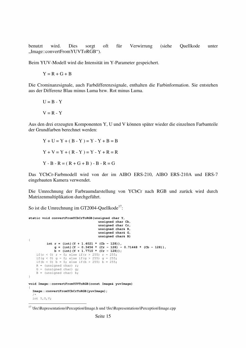
So ist die Umrechnung im GT2004-Quellkode17:
static void convertFromYCbCrToRGB(unsigned char Y,
unsigned char Cb,
unsigned char Cr,
unsigned char& R,
unsigned char& G,
unsigned char& B)
{
int r = (int)(Y + 1.4021 * (Cb - 128)),
g = (int)(Y - 0.3456 * (Cr - 128) - 0.71448 * (Cb - 128)),
b = (int)(Y + 1.7710 * (Cr - 128));
if(r < 0) r = 0; else if(r > 255) r = 255;
if(g < 0) g = 0; else if(g > 255) g = 255;
if(b < 0) b = 0; else if(b > 255) b = 255;
R = (unsigned char) r;
G = (unsigned char) g;
B = (unsigned char) b;
}
void Image::convertFromYUVToRGB(const Image& yuvImage)
{
Image::convertFromYCbCrToRGB(yuvImage);
/*
int Y,U,V;
17 \Src\Representations\Perception\Image.h und \Src\Representations\Perception\Image.cpp
Seite 16
int R,G,B;
for(int y=0; y < yuvImage.cameraInfo.resolutionHeight; y++)
{
for(int x=0; x < yuvImage.cameraInfo.resolutionWidth; x++)
{
Y = yuvImage.image[y][0][x];
U = yuvImage.image[y][1][x];
V = yuvImage.image[y][2][x];
R = (int)(Y + 1.140 * (U - 128));
G = (int)(Y - 0.394 * (V - 128) - 0.581 * (U - 128));
B = (int)(Y + 2.028 * (V - 128));
if(R < 0) R = 0; if(R > 255) R = 255;
if(G < 0) G = 0; if(G > 255) G = 255;
if(B < 0) B = 0; if(B > 255) B = 255;
image[y][0][x] = (unsigned char)R;
image[y][1][x] = (unsigned char)G;
image[y][2][x] = (unsigned char)B;
}
}
this->cameraInfo = yuvImage.cameraInfo;
*/
}
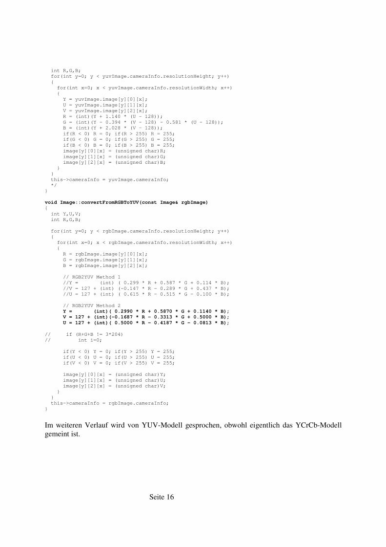
void Image::convertFromRGBToYUV(const Image& rgbImage)
{
int Y,U,V;
int R,G,B;
for(int y=0; y < rgbImage.cameraInfo.resolutionHeight; y++)
{
for(int x=0; x < rgbImage.cameraInfo.resolutionWidth; x++)
{
R = rgbImage.image[y][0][x];
G = rgbImage.image[y][1][x];
B = rgbImage.image[y][2][x];
// RGB2YUV Method 1
//Y = (int) ( 0.299 * R + 0.587 * G + 0.114 * B);
//V = 127 + (int) (-0.147 * R - 0.289 * G + 0.437 * B);
//U = 127 + (int) ( 0.615 * R - 0.515 * G - 0.100 * B);
// RGB2YUV Method 2
Y = (int)( 0.2990 * R + 0.5870 * G + 0.1140 * B);
V = 127 + (int)(-0.1687 * R - 0.3313 * G + 0.5000 * B);
U = 127 + (int)( 0.5000 * R - 0.4187 * G - 0.0813 * B);
// if (R+G+B != 3*204)
// int i=0;
if(Y < 0) Y = 0; if(Y > 255) Y = 255;
if(U < 0) U = 0; if(U > 255) U = 255;
if(V < 0) V = 0; if(V > 255) V = 255;
image[y][0][x] = (unsigned char)Y;
image[y][1][x] = (unsigned char)U;
image[y][2][x] = (unsigned char)V;
}
}
this->cameraInfo = rgbImage.cameraInfo;
}
Im weiteren Verlauf wird von YUV-Modell gesprochen, obwohl eigentlich das YCrCb-Modell gemeint ist.
Seite 17
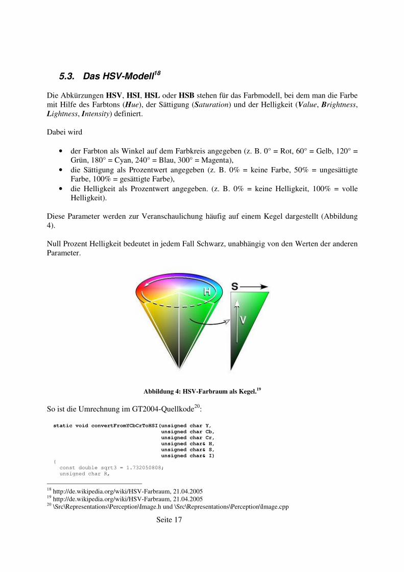
5.3. Das HSV-Modell18
Die Abkürzungen HSV, HSI, HSL oder HSB stehen für das Farbmodell, bei dem man die Farbe mit Hilfe des Farbtons (Hue), der Sättigung (Saturation) und der Helligkeit (Value, Brightness, Lightness, Intensity) definiert.
Dabei wird
• der Farbton als Winkel auf dem Farbkreis angegeben (z. B. 0° = Rot, 60° = Gelb, 120° = Grün, 180° = Cyan, 240° = Blau, 300° = Magenta),
• die Sättigung als Prozentwert angegeben (z. B. 0% = keine Farbe, 50% = ungesättigte Farbe, 100% = gesättigte Farbe),
• die Helligkeit als Prozentwert angegeben. (z. B. 0% = keine Helligkeit, 100% = volle Helligkeit).
Diese Parameter werden zur Veranschaulichung häufig auf einem Kegel dargestellt (Abbildung 4).
Null Prozent Helligkeit bedeutet in jedem Fall Schwarz, unabhängig von den Werten der anderen Parameter.
Abbildung 4: HSV-Farbraum als Kegel.19
So ist die Umrechnung im GT2004-Quellkode20:
static void convertFromYCbCrToHSI(unsigned char Y,
unsigned char Cb,
unsigned char Cr,
unsigned char& H,
unsigned char& S,
unsigned char& I)
{
const double sqrt3 = 1.732050808;
unsigned char R,
18 http://de.wikipedia.org/wiki/HSV-Farbraum, 21.04.2005 19 http://de.wikipedia.org/wiki/HSV-Farbraum, 21.04.2005 20 \Src\Representations\Perception\Image.h und \Src\Representations\Perception\Image.cpp
Seite 18
G,
B;
convertFromYCbCrToRGB(Y, Cb, Cr, R, G, B);
I = R;
if(G > I) I = G;
if(B > I) I = B;
if(I)
{
S = R;
if(G < S) S = G;
if(B < S) S = B;
S = (unsigned char) (255 - 255 * S / I);
if(S)
{
int h = int(atan2(sqrt3 * (G - B), 2 * R - G - B) / pi2 * 256);
if(h > 256) h -= 256;
else if(h < 0) h += 256;
H = (unsigned char) h;
}
else
H = 0;
}
else
S = H = 0;
}
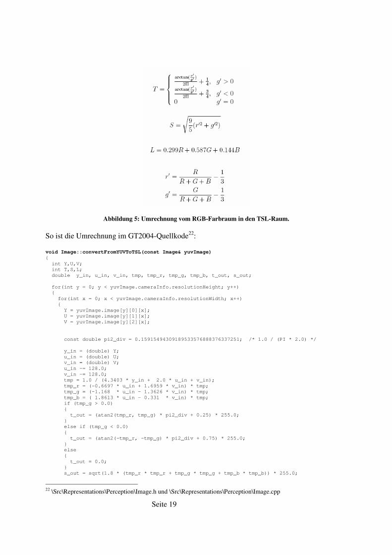
5.4. Das TSL-Modell21
Dieses Farbmodell wird häufig in der Gesichtserkennung eingesetzt, da es sehr gut zum Erkennen der Hautfarbe geeignet ist. Es wird beispielsweise vom German Team (Deutschland) und dem Team ASURA (Japan) für die Farbklassifikation benutzt.
Die Parameter tint (T), saturation (S) und luminance (L) werden durch die Gleichungen (Abbildung 5) definiert. Diese beschreiben die Konvertierung vom RGB-Farbraum in den TSL-Raum.
21 Passow, J. Diplomarbeit: Geometrieidentifikation aus den Kamerabildern mobiler autonomer Systeme in der Sony
Four-legged Robot League. Universität der Freien und Hansestadt Hamburg, Fachbereich Informatik, 2004. Seite 22f.
Seite 19
Abbildung 5: Umrechnung vom RGB-Farbraum in den TSL-Raum.
So ist die Umrechnung im GT2004-Quellkode22:
void Image::convertFromYUVToTSL(const Image& yuvImage)
{
int Y,U,V;
int T,S,L;
double y_in, u_in, v_in, tmp, tmp_r, tmp_g, tmp_b, t_out, s_out;
for(int y = 0; y < yuvImage.cameraInfo.resolutionHeight; y++)
{
for(int x = 0; x < yuvImage.cameraInfo.resolutionWidth; x++)
{
Y = yuvImage.image[y][0][x];
U = yuvImage.image[y][1][x];
V = yuvImage.image[y][2][x];
const double pi2_div = 0.15915494309189533576888376337251; /* 1.0 / (PI * 2.0) */
y_in = (double) Y;
u_in = (double) U;
v_in = (double) V;
u_in -= 128.0;
v_in -= 128.0;
tmp = 1.0 / (4.3403 * y_in + 2.0 * u_in + v_in);
tmp_r = (-0.6697 * u_in + 1.6959 * v_in) * tmp;
tmp_g = (-1.168 * u_in - 1.3626 * v_in) * tmp;
tmp_b = ( 1.8613 * u_in - 0.331 * v_in) * tmp;
if (tmp_g > 0.0)
{
t_out = (atan2(tmp_r, tmp_g) * pi2_div + 0.25) * 255.0;
}
else if (tmp_g < 0.0)
{
t_out = (atan2(-tmp_r, -tmp_g) * pi2_div + 0.75) * 255.0;
}
else
{
t_out = 0.0;
}
s_out = sqrt(1.8 * (tmp_r * tmp_r + tmp_g * tmp_g + tmp_b * tmp_b)) * 255.0;
22 \Src\Representations\Perception\Image.h und \Src\Representations\Perception\Image.cpp
Seite 20
/* Crop T and S values */
if (t_out < 0.0)
{
t_out = 0.0;
}
else if (t_out > 255.0)
{
t_out = 255.0;
}
if (s_out < 0.0)
{
s_out = 0.0;
}
else if (s_out > 255.0)
{
s_out = 255.0;
}
T = (unsigned char) t_out;
S = (unsigned char) s_out;
L = Y;
image[y][0][x] = (unsigned char)T;
image[y][1][x] = (unsigned char)S;
image[y][2][x] = (unsigned char)L;
}
}
this->cameraInfo = yuvImage.cameraInfo;
}
Seite 21
6. Analyse 6.1. Testaufnahmen
Für die Analyse wurden so genannte log-Dateien aufgenommen. Bei den Aufnahmen wurden von einem stehenden Roboter unter verschiedenen Lichtverhältnissen Kamerabilder aufgenommen. Dabei wurden zuerst alle Lampen eingeschaltet und dann nacheinander stufenweise abgeschaltet, bis es ganz dunkel im Labor war. Ferner wurde bei jeder Änderung der Lichtverhältnissen zusätzlich jedes Objekt nacheinander direkt von allen Seiten bestrahlt.
Dieses Verfahren wurde mit verschiedenen Robotertypen in unterschiedlichen Roboterpositionen wiederholt.
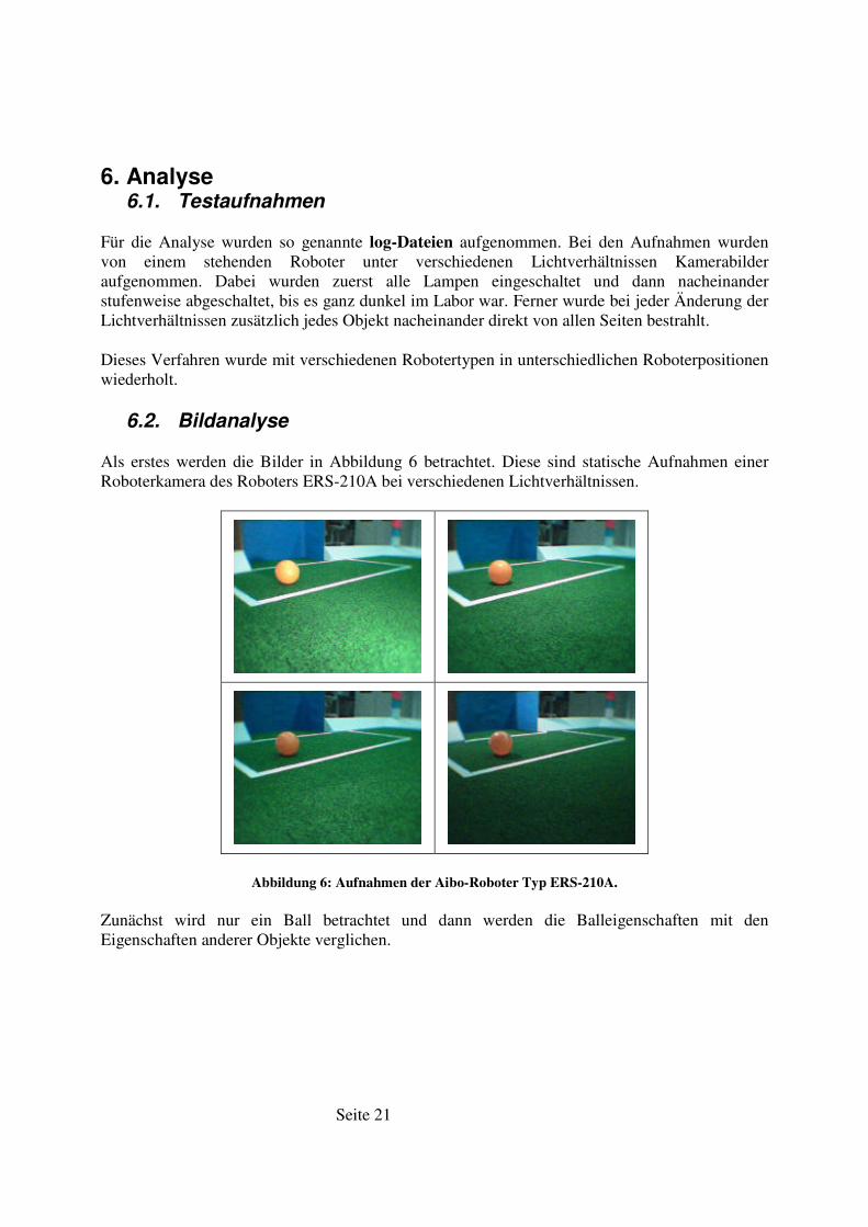
6.2. Bildanalyse
Als erstes werden die Bilder in Abbildung 6 betrachtet. Diese sind statische Aufnahmen einer Roboterkamera des Roboters ERS-210A bei verschiedenen Lichtverhältnissen.
Abbildung 6: Aufnahmen der Aibo-Roboter Typ ERS-210A.
Zunächst wird nur ein Ball betrachtet und dann werden die Balleigenschaften mit den Eigenschaften anderer Objekte verglichen.
Seite 22
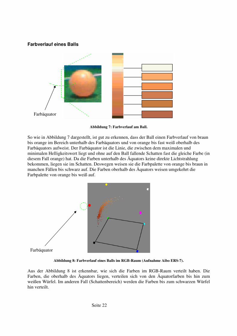
Farbverlauf eines Balls
Abbildung 7: Farbverlauf am Ball.
So wie in Abbildung 7 dargestellt, ist gut zu erkennen, dass der Ball einen Farbverlauf von braun bis orange im Bereich unterhalb des Farbäquators und von orange bis fast weiß oberhalb des Farbäquators aufweist. Der Farbäquator ist die Linie, die zwischen dem maximalen und minimalen Helligkeitswert liegt und ohne auf den Ball fallende Schatten fast die gleiche Farbe (in diesem Fall orange) hat. Da die Farben unterhalb des Äquators keine direkte Lichtstrahlung bekommen, liegen sie im Schatten. Deswegen weisen sie die Farbpalette von orange bis braun in manchen Fällen bis schwarz auf. Die Farben oberhalb des Äquators weisen umgekehrt die Farbpalette von orange bis weiß auf.
Abbildung 8: Farbverlauf eines Balls im RGB-Raum (Aufnahme Aibo ERS-7).
Aus der Abbildung 8 ist erkennbar, wie sich die Farben im RGB-Raum verteilt haben. Die Farben, die oberhalb des Äquators liegen, verteilen sich von den Äquatorfarben bis hin zum weißen Würfel. Im anderen Fall (Schattenbereich) werden die Farben bis zum schwarzen Würfel hin verteilt.
Farbäquator
Farbäquator
Seite 23
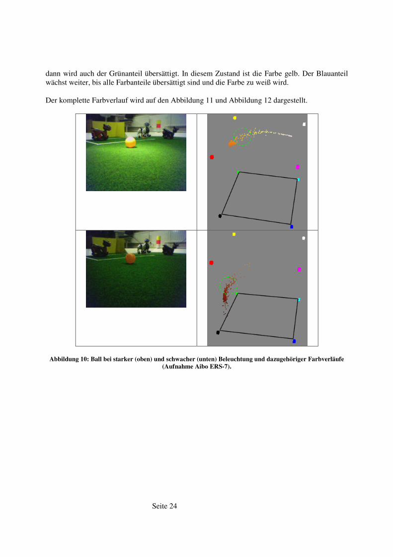
Es stellt sich die Frage, wie die Farbverteilung bei einem extrem hellen und extrem dunklen Zustand aussieht.
In Abbildung 10 ist erkennbar, dass bei sehr starker Beleuchtung, orange zu gelb und weiter zu weiß wird. Die Ursache liegt in dem Aufbau des CCD-Chip der Kamera.
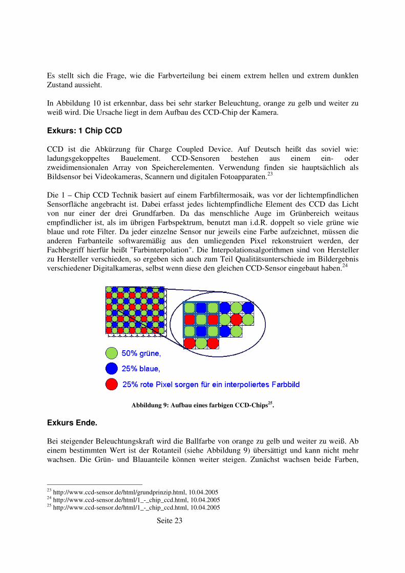
Exkurs: 1 Chip CCD
CCD ist die Abkürzung für Charge Coupled Device. Auf Deutsch heißt das soviel wie: ladungsgekoppeltes Bauelement. CCD-Sensoren bestehen aus einem ein- oder zweidimensionalen Array von Speicherelementen. Verwendung finden sie hauptsächlich als Bildsensor bei Videokameras, Scannern und digitalen Fotoapparaten.23
Die 1 – Chip CCD Technik basiert auf einem Farbfiltermosaik, was vor der lichtempfindlichen Sensorfläche angebracht ist. Dabei erfasst jedes lichtempfindliche Element des CCD das Licht von nur einer der drei Grundfarben. Da das menschliche Auge im Grünbereich weitaus empfindlicher ist, als im übrigen Farbspektrum, benutzt man i.d.R. doppelt so viele grüne wie blaue und rote Filter. Da jeder einzelne Sensor nur jeweils eine Farbe aufzeichnet, müssen die anderen Farbanteile softwaremäßig aus den umliegenden Pixel rekonstruiert werden, der Fachbegriff hierfür heißt "Farbinterpolation". Die Interpolationsalgorithmen sind von Hersteller zu Hersteller verschieden, so ergeben sich auch zum Teil Qualitätsunterschiede im Bildergebnis verschiedener Digitalkameras, selbst wenn diese den gleichen CCD-Sensor eingebaut haben.24
Abbildung 9: Aufbau eines farbigen CCD-Chips25
.
Exkurs Ende.
Bei steigender Beleuchtungskraft wird die Ballfarbe von orange zu gelb und weiter zu weiß. Ab einem bestimmten Wert ist der Rotanteil (siehe Abbildung 9) übersättigt und kann nicht mehr wachsen. Die Grün- und Blauanteile können weiter steigen. Zunächst wachsen beide Farben,
23 http://www.ccd-sensor.de/html/grundprinzip.html, 10.04.2005 24 http://www.ccd-sensor.de/html/1_-_chip_ccd.html, 10.04.2005 25 http://www.ccd-sensor.de/html/1_-_chip_ccd.html, 10.04.2005
Seite 24
dann wird auch der Grünanteil übersättigt. In diesem Zustand ist die Farbe gelb. Der Blauanteil wächst weiter, bis alle Farbanteile übersättigt sind und die Farbe zu weiß wird.
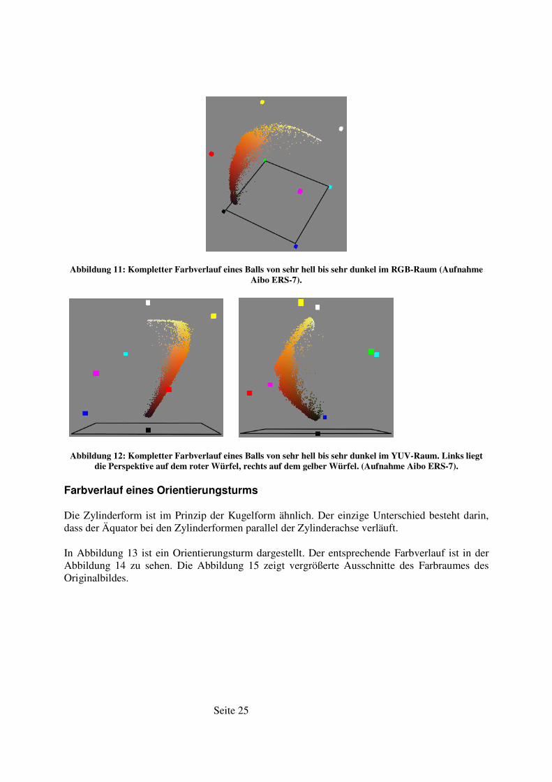
Der komplette Farbverlauf wird auf den Abbildung 11 und Abbildung 12 dargestellt.
Abbildung 10: Ball bei starker (oben) und schwacher (unten) Beleuchtung und dazugehöriger Farbverläufe
(Aufnahme Aibo ERS-7).
Seite 25
Abbildung 11: Kompletter Farbverlauf eines Balls von sehr hell bis sehr dunkel im RGB-Raum (Aufnahme
Aibo ERS-7).
Abbildung 12: Kompletter Farbverlauf eines Balls von sehr hell bis sehr dunkel im YUV-Raum. Links liegt
die Perspektive auf dem roter Würfel, rechts auf dem gelber Würfel. (Aufnahme Aibo ERS-7).
Farbverlauf eines Orientierungsturms
Die Zylinderform ist im Prinzip der Kugelform ähnlich. Der einzige Unterschied besteht darin, dass der Äquator bei den Zylinderformen parallel der Zylinderachse verläuft.
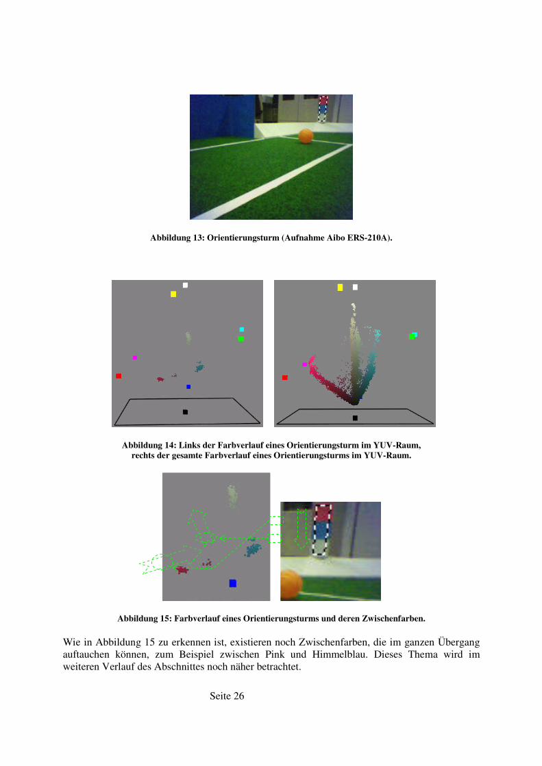
In Abbildung 13 ist ein Orientierungsturm dargestellt. Der entsprechende Farbverlauf ist in der Abbildung 14 zu sehen. Die Abbildung 15 zeigt vergrößerte Ausschnitte des Farbraumes des Originalbildes.
Seite 26
Abbildung 13: Orientierungsturm (Aufnahme Aibo ERS-210A).
Abbildung 14: Links der Farbverlauf eines Orientierungsturm im YUV-Raum,
rechts der gesamte Farbverlauf eines Orientierungsturms im YUV-Raum.
Abbildung 15: Farbverlauf eines Orientierungsturms und deren Zwischenfarben.
Wie in Abbildung 15 zu erkennen ist, existieren noch Zwischenfarben, die im ganzen Übergang auftauchen können, zum Beispiel zwischen Pink und Himmelblau. Dieses Thema wird im weiteren Verlauf des Abschnittes noch näher betrachtet.
Seite 27
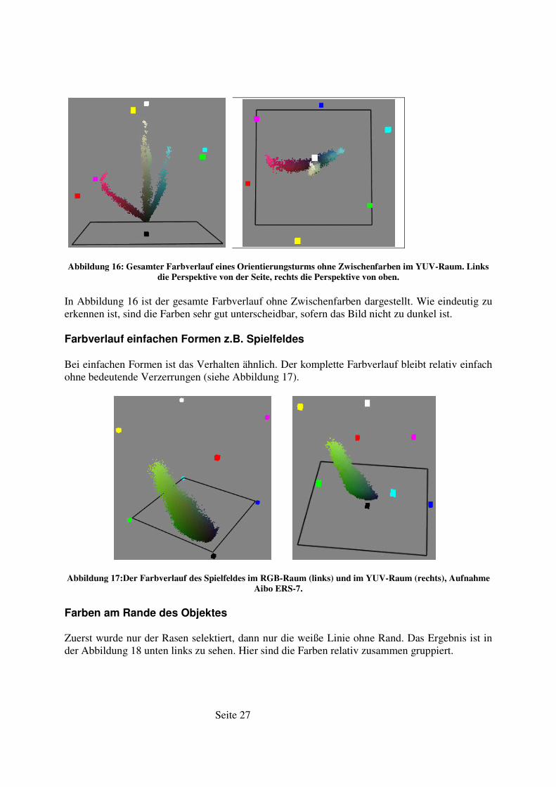
Abbildung 16: Gesamter Farbverlauf eines Orientierungsturms ohne Zwischenfarben im YUV-Raum. Links
die Perspektive von der Seite, rechts die Perspektive von oben.
In Abbildung 16 ist der gesamte Farbverlauf ohne Zwischenfarben dargestellt. Wie eindeutig zu erkennen ist, sind die Farben sehr gut unterscheidbar, sofern das Bild nicht zu dunkel ist.
Farbverlauf einfachen Formen z.B. Spielfeldes
Bei einfachen Formen ist das Verhalten ähnlich. Der komplette Farbverlauf bleibt relativ einfach ohne bedeutende Verzerrungen (siehe Abbildung 17).
Abbildung 17:Der Farbverlauf des Spielfeldes im RGB-Raum (links) und im YUV-Raum (rechts), Aufnahme
Aibo ERS-7.
Farben am Rande des Objektes
Zuerst wurde nur der Rasen selektiert, dann nur die weiße Linie ohne Rand. Das Ergebnis ist in der Abbildung 18 unten links zu sehen. Hier sind die Farben relativ zusammen gruppiert.

Seite 28
Als nächstes wurde die Linie mit dem Rasen zusammen selektiert (siehe Abbildung 18 oben rechts und links und unten rechts). Es sind deutlich mehr Punkten zu erkennen, die zwischen den Gruppen liegen.
Abbildung 18: Farben am Rande des Objektes.
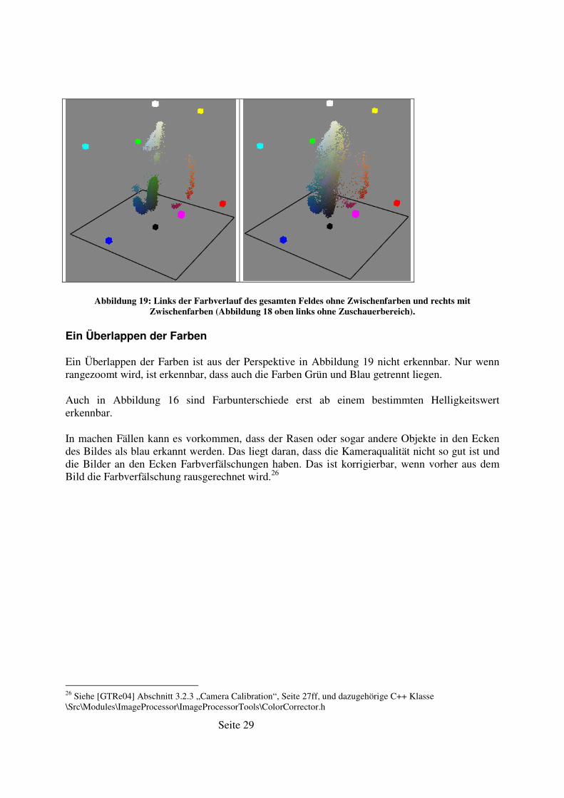
In der Abbildung 19 sind die Farbverläufe des gesamten Feldes im YUV-Farbraum zu erkennen. Links ohne Zwischenfarben, rechts mit Zwischenfarben. In der rechten Abbildung ist es sehr schwer, z.B. die weiße Farbe von der grünen zu unterscheiden, da der Übergang nicht eindeutig erkennbar ist. Links hingegen ist es einfacher, weil weiß und grün sehr weit auseinander liegen.
Seite 29
Abbildung 19: Links der Farbverlauf des gesamten Feldes ohne Zwischenfarben und rechts mit
Zwischenfarben (Abbildung 18 oben links ohne Zuschauerbereich).
Ein Überlappen der Farben
Ein Überlappen der Farben ist aus der Perspektive in Abbildung 19 nicht erkennbar. Nur wenn rangezoomt wird, ist erkennbar, dass auch die Farben Grün und Blau getrennt liegen.
Auch in Abbildung 16 sind Farbunterschiede erst ab einem bestimmten Helligkeitswert erkennbar.
In machen Fällen kann es vorkommen, dass der Rasen oder sogar andere Objekte in den Ecken des Bildes als blau erkannt werden. Das liegt daran, dass die Kameraqualität nicht so gut ist und die Bilder an den Ecken Farbverfälschungen haben. Das ist korrigierbar, wenn vorher aus dem Bild die Farbverfälschung rausgerechnet wird.26
26 Siehe [GTRe04] Abschnitt 3.2.3 „Camera Calibration“, Seite 27ff, und dazugehörige C++ Klasse \Src\Modules\ImageProcessor\ImageProcessorTools\ColorCorrector.h
Seite 30
7. Farbklassifikationsmodule
Farbklassifikationsmodule (ColorTableModule) dienen der Zuordnung eines Farbwertes zu einer Farbklasse. Vor der Benutzung des Farbklassifikationsmoduls müssen noch die Kameraeinstellungen vorgenommen werden.
Die Kameras haben dabei folgende Einstellungen27:
1. Weißausgleich – innen, fluoreszent, draußen (White balance – indoor, fluorescent, outdoor);
2. Kameraverstärkung – hoch, mittel, schwach (Camera gain – high, mid, slow); 3. Kameraverschlussgeschwindigkeit – schnell, mittel, langsam (Shutter speed – fast,
mid, slow).
Sie sind in der Datei „\Src\Representations\Perception\CameraParameters.h“ implementiert und können mittels der Datei „\Src\Platform\Aperios1.3.2\Sensors.h“ an den Roboter gesendet werden.
Eine Farbverfälschung der Kamera kann mit der Klasse ColorCorrector in der Datei “ColorCorrector.h“ aus dem Verzeichnis „\Src\Modules\ImageProcessor\ImageProcessorTools\“ behoben werden.
7.1. ColorTable32 und ColorTable64
ColorTable64 ist in den Dateien „ColorTable64.h“ und „ColorTable64.cpp“ im Verzeichnis „\Src\Representations\Perception\“ implementiert. Im gleichen Verzeichnis befindet sich „ColorTable32.h“ und „ColorTable32.cpp“. ColorTable64 ist eine Weiterentwicklung des ColorTable32.
ColorTable64 ist ein dreidimensionales Array [64x64x64] für Y-, U- und V-Werte. Für jede Dimension ist ein Wertebereich von 0 bis 63 definiert. Da ein Pixel für jeden Wert einen Wertebereich von 0 bis 255 hat, wird jede Dimension bei der Farberkennung restlos durch vier geteilt.
In dem Array ist die entsprechende Zuordnung zu einer Farbklasse gespeichert.
ColorTable64 ist nur eine Erweiterung des ColorTable32, in dem von der Dimension [8x64x64] zu [64x64x64] gewechselt worden ist.
Vorteile:
• Die Kamera liefert Bilder im YCrCb-Format, daher ist keine Konvertierung nötig, und es gibt keinen Performanceverlust.
• Für ein Pixel sind nur drei restlose Divisionen und ein Speicherzugriff nötig.
27 In OPENR von Sony sind mehr Einstellungen vorhanden. Hier werden nur mit GT2004 einstellbare Einstellungen angeschaut.
Seite 31
• Speichersparend, da ein Eintrag im Array für 64 (4x4x4) YUV-Werte steht. Speicherbedarf ist 643 = 262144 Werte. Wenn für jeden Wert ein Byte verwendet wird, dann sind das 256 KBytes. Sonst müssten 2563 = 16777216 Werte verwendet werden, oder 16384 KBytes.
Nachteile:
• Statisch. • Relativ mühsame Erstellung. • Es bleiben immer „Löcher“ in der Matrix (Array), die bei der Kalibrierung entstehen. • Keine Korrektur der Farbverfälschung der Kamera wird verwendet. • Objektränder werden mitberücksichtigt. • Schon bei mittleren Lichtänderungen werden Farben falsch oder nicht erkannt. • „NoColor“ wird in Außenbereich eingesetzt und damit die normalen Farben
überschrieben. Oder bei leichten Lichtänderungen wird „NoColor“ als normales Feldobjekt erkannt.
• Die Grenze zwischen zwei Farben ist unvorhersehbar. Sie muss oft frei positionierbar verlaufen und einstellbar sein und nicht parallel zur Achse verlaufen.
• Genauigkeit ist relativ, da ein Eintrag im Array für 64 (4x4x4) YUV-Werte steht.
Vorschläge:
• Es kann an der Stelle einer “Durch-Vier-Division“ eine Right Shift28-Operation eingesetzt werden, um Performance zu gewinnen.
7.2. ColorTableTSL
ColorTableTSL ist in den Dateien „ColorTableTSL.h“ und „ColorTableTSL.cpp“ im Verzeichnis „\Src\Representations\Perception\“ implementiert.
ColorTableTSL hat auch fast wie ColorTable64 ein dreidimensionales Array [32*64*64] für Y-, U- und V-Werte. Außerdem sind für jede Farbe Tmin-, Tmax-, Smin-, Smax-, Lmin- und Lmax-Werte definiert. Damit kein Performanceverlust auftritt, werden vor der Benutzung der ColorTableTSL die TSL-Werte in das Array transferiert. D.h. bei der Kalibrierung werden einzelnen Pixel aus dem YUV-Farbsystem in das TSL-Farbsystem konvertiert. Danach werden Bereiche (die Werte Tmin, Tmax, Smin, Smax, Lmin und Lmax) bestimmt und abgespeichert. Ein Roboter lädt die gespeicherte Datei und konvertiert die Bereiche in den YUV-Farbraum. Somit werden beim Zugriff auf ein Pixel nur drei Dimensionsanpassungen (Right Shift 2 oder Right Shift 3) und ein Speicherzugriff durchgeführt.
Vorteile:
• Die Kamera liefert Bilder im YCrCb-Format, daher ist keine Konvertierung nötig, und es gibt keinen Performanceverlust im Echtzeitbetrieb.
• Für ein Pixel sind nur drei Right Shifts und ein Speicherzugriff nötig.
28 Bitwiese Left Shift und Right Shift Operatoren
Seite 32
• Speichersparend, da ein Eintrag im Array für 128 (8x4x4) YUV-Werte steht. Speicherbedarf ist 32*64*64 = 131072 Werte. Wenn für jedes Wert ein Byte verwendet wird, dann sind das 128 KBytes. Sonst müssten 2563 = 16777216 Werte verwendet werden, oder 16384 KBytes.
• Eine Korrektur der Farbverfälschung der Kamera wird verwendet. • Relativ schnelle Erstellung und leichte Anpassung. • Bei mittleren Lichtveränderungen werden Farben gut erkannt. • Reihenfolge der Farben ist einstellbar.
Nachteile:
• Statisch. • Es bleiben immer „Löcher“ in der Matrix (Array), die bei der Kalibrierung entstehen. • Objektränder werden mitberücksichtigt. • Die Grenze zwischen zwei Farben im YUV-Farbraum ist unvorhersehbar. • Korrektur der Farbverfälschung der Kamera funktioniert nicht gut. • Genauigkeit ist relativ, da ein Eintrag im Array für 128 (8x4x4) YUV-Werte steht. • Die Reihenfolge der Farben kann einige untergeordnete Farben benachteiligen. Zum
Beispiel kann Pink so definiert werden, dass Rot nicht mehr erkannt wird. • T – Histogramm funktioniert fehlerhaft. • „Auto“ – Taste funktioniert fehlerhaft.
7.3. HSIColorTable
HSIColorTable ist in den Dateien „HSIDataTypes.h“ und „HSIDataTypes.cpp“ im Verzeichnis „\Src\RobotControl\HSITools\“ implementiert.
HSIColorTable verwendet direkt die Klasse ColorTable64. Außerdem sind für jede Farbe Hmin-, Hmax-, Smin-, Smax-, Imin- und Imax-Werte definiert. Damit kein Performanceverlust auftritt, werden vor der Benutzung der HSIColorTable die HSI-Werte in die Instanz ColorTable64 konvertiert, genau wie im TSLColorTable.
Somit werden beim Zugriff auf ein Pixel nur drei Dimensionsanpassungen (restlose Division durch 4) und ein Speicherzugriff durchgeführt.
Vorteile:
• Die Kamera liefert Bilder im YCrCb-Format, daher keine Konvertierung nötig, und es gibt kein Performanceverlust im Echtzeitbetrieb.
• Für einen Pixel sind nur drei restlose Divisionen und ein Speicherzugriff nötig. • Speichersparend, da ein Eintrag im Array für 64 (4x4x4) YUV-Werte steht.
Speicherbedarf ist 643 = 262144 Werte. Wenn für jeden Wert ein Byte verwendet wird, dann sind das 256 KBytes. Sonst müssten 2563 = 16777216 Werte verwendet werden, oder 16384 KBytes.
• Relativ schnelle Erstellung und leichte Anpassung.
Seite 33
• Bei mittleren Lichtänderungen werden Farben schwächer als ColorTableTSL erkannt, dennoch relativ gut.
Nachteile:
• Statisch. • Es bleiben immer „Löcher“ in der Matrix (Array), die bei der Kalibrierung entstehen. • Keine Korrektur der Farbverfälschung der Kamera wird verwendet. • Objektränder werden mitberücksichtigt. • Die Grenze zwischen zwei Farben im YUV-Farbraum ist unvorhersehbar. • Genauigkeit ist relativ, da ein Eintrag im Array für 64 (4x4x4) YUV-Werte steht. • Die Reihenfolge der Farben ist nicht einstellbar. • Die Reihenfolge der Farben kann einige untergeordnete Farben benachteiligen. Zum
Beispiel kann Pink so definiert werden, dass Rot nicht mehr erkannt wird.
Seite 34
8. Dynamische versus statische Farbklassifikation.
Leider ist es so, dass die Performance an erster Stelle steht. Schon die einfachen Filter z. B. Sobel-Filter schaffen Performanceeinbußen. Es ist möglich, einen halbautomatischen Algorithmus zu implementieren. Die Roboter senden Bilder an einen Desktop-PC, der notwendige Berechnungen ausführt. Das ist leider nur außerhalb des Spieles erlaubt, stellt aber eine Basis zur automatischen Farberkennung dar. Außerdem bietet dies eine große Erleichterung bei der Einstellung. So könnten alle Roboter individuell eingestellt werden.
Bei statischen Tabellen muss zusätzlich Speicherkapazität berücksichtigt werden.
Der Vorteil statischer Tabellen liegt in ihrer Schnelligkeit. Dynamische Verfahren verlangsamen die Prozesse.
Der Nachteil statischer Tabellen ist allerdings, dass sie vor dem Spiel oder dem Challenge bestimmt werden müssen und alle zu erwartenden Lichtänderungen beinhalten müssen. Bei dynamischen Verfahren ist das nicht notwendig.
Seite 35
9. Analyse, Implementation und Einbindung in den Hamburg Dog Bots-Code
Dies ist eine kurze zusammenfassende Bewertung der Kapitel 6 bis 8:
Alle Objekte haben bestimmte Farbverläufe, die ab einer bestimmten Beleuchtung auseinanderliegen. Dabei müssen keine Kanten berücksichtigt werden. Der Zuschauerbereich muss bei der Kalibrierung nicht berücksichtigt werden. Aber das kann durchaus normale Farbklassen beinhalten. Bevor mit einem Bild gearbeitet wird, muss die Kameraverzerrung errechnet werden.
Alle oben beschriebene Module verwenden ColorTable64 (YUV-Farbraum) oder generieren selbst eine ähnliche Tabelle. Bei allen Verfahren wird nur die statische Farberkennung verwendet.
Alle oben beschriebene Bewertungen führen zu der Lösung: Aufteilung in getrennte
Farbräume und Generierung der ColorTable64 oder einer vergleichbaren
Farbklassifikationsmodule.
So kann der gesamte YUV-Farbraum in Unterräume aufgeteilt werden. Jeder Unterraum bestimmt eine Farbe. Das ist möglich mit Hilfe von Ebenen oder Trennwänden. Eine Trennwand kann mit vier Parametern beschrieben werden. Die Gleichung sieht so aus:
A*Y + B*U + C*V + D = 0
wobei A, B, C, D Konstanten sind, Vektor (A,B,C) ein Normalvektor der Ebene, und D ein Verschiebungsfaktor der Ebene vom Punkt (0,0,0) in Richtung des Normalvektors.
Es kann auch leicht festgestellt werden, ob ein Punkt (y,u,v) sich auf der einen oder der anderen Seite von der Ebene oder sogar auf der Ebene befindet. Dafür wird der Wert R bestimmt:
R = A*y + B*u + C*v + D.
• Wenn R = 0, dann ist der Punkt (y,u,v) auf der Ebene; • Wenn R > 0, dann ist der Punkt (y,u,v) auf der Seite der Ebene, die in der Richtung vom
Normalvektor aus der Ebene zeigt; • Wenn R < 0, dann ist der Punkt (y,u,v) auf der anderen Seite der Ebene.
Weiter sind es nur zwei Fälle von Bedeutung: R ≥ 0 und R < 0.
Somit ist schnell feststellbar (drei Multiplikationen, drei Additionen und ein Vergleich), ob ein Punkt sich auf der einen oder der anderen Seite befindet.
Trennwände müssen so eingesetzt werden, dass sie genau zwischen den Farbmengen liegen. Die Reihenfolge der Farben muss einstellbar sein.
Die Aufnahmen müssen bei allen Lichtverhältnissen gemacht werden.
Seite 36
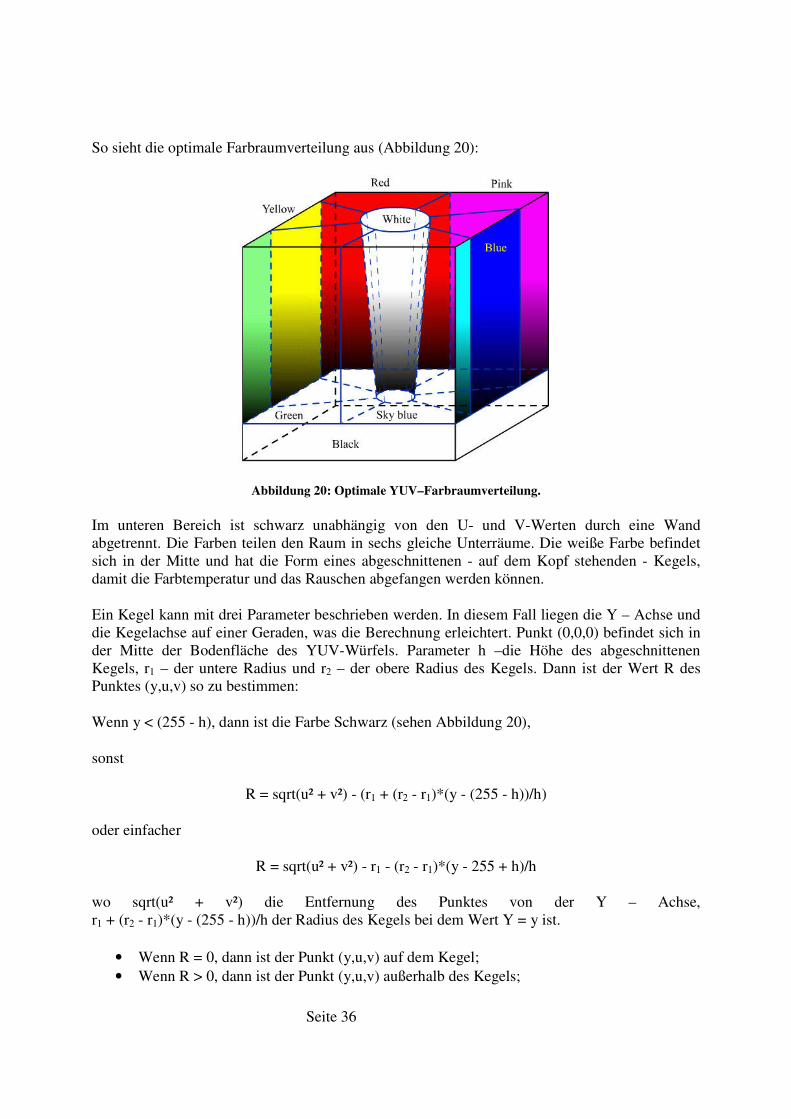
So sieht die optimale Farbraumverteilung aus (Abbildung 20):
Abbildung 20: Optimale YUV–Farbraumverteilung.
Im unteren Bereich ist schwarz unabhängig von den U- und V-Werten durch eine Wand abgetrennt. Die Farben teilen den Raum in sechs gleiche Unterräume. Die weiße Farbe befindet sich in der Mitte und hat die Form eines abgeschnittenen - auf dem Kopf stehenden - Kegels, damit die Farbtemperatur und das Rauschen abgefangen werden können.
Ein Kegel kann mit drei Parameter beschrieben werden. In diesem Fall liegen die Y – Achse und die Kegelachse auf einer Geraden, was die Berechnung erleichtert. Punkt (0,0,0) befindet sich in der Mitte der Bodenfläche des YUV-Würfels. Parameter h –die Höhe des abgeschnittenen Kegels, r1 – der untere Radius und r2 – der obere Radius des Kegels. Dann ist der Wert R des Punktes (y,u,v) so zu bestimmen:
Wenn y < (255 - h), dann ist die Farbe Schwarz (sehen Abbildung 20),
sonst
R = sqrt(u² + v²) - (r1 + (r2 - r1)*(y - (255 - h))/h)
oder einfacher
R = sqrt(u² + v²) - r1 - (r2 - r1)*(y - 255 + h)/h
wo sqrt(u² + v²) die Entfernung des Punktes von der Y – Achse, r1 + (r2 - r1)*(y - (255 - h))/h der Radius des Kegels bei dem Wert Y = y ist.
• Wenn R = 0, dann ist der Punkt (y,u,v) auf dem Kegel; • Wenn R > 0, dann ist der Punkt (y,u,v) außerhalb des Kegels;
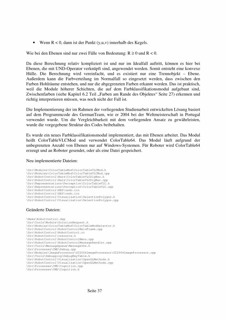
Seite 37
• Wenn R < 0, dann ist der Punkt (y,u,v) innerhalb des Kegels.
Wie bei den Ebenen sind nur zwei Fälle von Bedeutung: R ≥ 0 und R < 0.
Da diese Berechnung relativ kompliziert ist und nur im Idealfall auftritt, können es hier bei Ebenen, die mit UND-Operator verknüpft sind, angewendet werden. Somit entsteht eine konvexe Hülle. Die Berechnung wird vereinfacht, und es existiert nur eine Trennobjekt – Ebene. Außerdem kann die Farbverteilung im Normalfall so eingesetzt werden, dass zwischen den Farben Hohlräume entstehen, und nur die abgegrenzten Farben erkannt werden. Das ist praktisch, weil die Module höherer Schichten, die auf dem Farbklassifikationsmodul aufgebaut sind, Zwischenfarben (siehe Kapitel 6.2 Teil „Farben am Rande des Objektes“ Seite 27) erkennen und richtig interpretieren müssen, was noch nicht der Fall ist.
Die Implementierung der im Rahmen der vorliegenden Studienarbeit entwickelten Lösung basiert auf dem Programmcode des GermanTeam, wie er 2004 bei der Weltmeisterschaft in Portugal verwendet wurde. Um die Vergleichbarkeit mit dem vorliegenden Ansatz zu gewährleisten, wurde die vorgegebene Struktur des Codes beibehalten.
Es wurde ein neues Farbklassifikationsmodul implementiert, das mit Ebenen arbeitet. Das Modul heißt ColorTableVLCMod und verwendet ColorTable64. Das Modul läuft aufgrund der unbegrenzten Anzahl von Ebenen nur auf Windows-Systemen. Für Roboter wird ColorTable64 erzeugt und an Roboter gesendet, oder als eine Datei gespeichert.
Neu implementierte Dateien:
\Src\Modules\ColorTableMod\ColorTableVLCMod.h
\Src\Modules\ColorTableMod\ColorTableVLCMod.cpp
\Src\RobotControl\Bars\ColorTableVLCDlgBar.h
\Src\RobotControl\Bars\ColorTableVLCDlgBar.cpp
\Src\Representations\Perception\ColorTableVLC.h
\Src\Representations\Perception\ColorTableVLC.cpp
\Src\RobotControl\RES\undo.ico
\Src\RobotControl\RES\redo.ico
\Src\RobotControl\Visualization\SelectionPolygon.h
\Src\RobotControl\Visualization\SelectionPolygon.cpp
Geänderte Dateien:
\Make\RobotControl.dsp
\Src\Tools\Module\SolutionRequest.h
\Src\Modules\ColorTableMod\ColorTableModSelector.h
\Src\RobotControl\RobotControlMainFrame.cpp
\Src\RobotControl\RobotControl.rc
\Src\RobotControl\resource.h
\Src\RobotControl\RobotControlMenu.cpp
\Src\RobotControl\RobotControlMessageHandler.cpp
\Src\Tools\MessageQueue\MessageIDs.h
\Src\Processes\CMD\Debug.cpp
\Src\Modules\ImageProcessor\GT2004ImageProcessor\GT2004ImageProcessor.cpp
\Src\Tools\Debugging\DebugKeyTable.h
\Src\RobotControl\Visualization\OpenGLMethods.h
\Src\RobotControl\Visualization\OpenGLMethods.cpp
\Src\Processes\CMD\Cognition.cpp
\Src\Processes\CMD\Cognition.h
Seite 38
10. Ausblick: Automatisierung der Farberkennung
Eine Automatisierung der Farberkennung kann die mühsame manuelle Einstellung erleichtern oder überflüssig machen. Dann können alle Roboter individuell und schnell eingestellt werden. Dabei müssen folgende Schritte gemacht werden:
1. Kantenerkennung 2. Feststellung der mittleren Farben und deren Bereiches 3. Bestimmung Spielfeldbereichs 4. Zuordnung festgestellten Farben zu definierten Farbklassen 5. Abgrenzung festgestellten Farbklassen durch Trennwände 6. Generierung neue ColorTable64
Es kann ein halbautomatischer Algorithmus eingesetzt werden. Dabei sendet ein Roboter ein Bild (oder mehrere Bilder) an einen Desktop-PC. Ein Benutzer selektiert mit bestimmten Farben alle Objekte im Bild (in den Bildern). Somit fallen die ersten vier Schritte der automatischen Farberkennung aus. Der Desktop-PC führt Schritte fünf und sechs aus, und sendet eine generierte Tabelle an den Roboter.
Eine ausreichende Betrachtung dieses Themas würde den Rahmen dieser Arbeit sprengen.
Seite 39
11. Fazit
Zunächst wurde eine Analyse des Farbverhalten verschiedener Objekte bei diversen Belichtungsstärken durchgeführt und verglichen.
Danach wurden bestehende Module des GermanTeam Projektes untersucht und Vor- und Nachteile sowie Gemeinsamkeiten festgestellt.
Weiter wurden die Möglichkeiten eines dynamischen Verfahrens der Farbklassifikation angedeutet.
Dann wurde ein Verfahren entwickelt, das in der Lage ist, das gestellte Ziel optimal auf Basis des Hamburg Dog Bots Projektes zu erreichen.
Es wurde dabei die Möglichkeit der automatischen Einstellungsmöglichkeit untersucht.
Auf Basis der Hamburg Dog Bots Quellcodes wurde das Verfahren implementiert, in das Projekt integriert und erprobt.
Obwohl die Einstellung manuell erfolgt und noch schwierig ist, können Roboter sehr gut die Farben klassifizieren. Erste wichtige Tests gab es bei den German Open 2005 in Paderborn.
Und so sah das Ergebnis aus:
„1.Platz!!! In der Variable Lighting Challenge - wo die Lichteinstellungen alle 20 Sek. verändert werden - konnte unser Spieler zwei mal ins Tor treffen. Als zusätzliches Hindernis zu den sich wechselnden Lichtverhältnissen gab es noch zwei passive Gegner. Diese wurden aber bei den gezielten Schüssen vom Mittelkreis beachtet und der Ball schlug zwei mal innerhalb 1:57 Minuten in den Kasten ein. Danach nahm er sich dann eine geistige Auszeit und versuchte den passiven Torwart richtig zu positionieren ,)
Der Stürmer der MS Hellhounds (Dortmund) konnte zwar auch zwei Treffer erzielen, brauchte aber länger (ca. 2:30 min)... Es gab insgesamt drei Minuten Zeit.
Damit sind wir deutsche Meister in dem inoffiziellen Wettbewerb der Variable Lighting Challenge!!!„29
Die Weiterentwicklung des automatischen Farberkennung bietet die Möglichkeit der schnellen, einfachen und individuellen Einstellung.
29 http://www.20six.de/HDB-GermanOpen2005, 20.04.2005.
Seite 40
12. Literaturliste
[BäKr04] Bässmann, H., Kreyss, J. Bildverarbeitung Ad Oculos. Springer, Berlin, 4. aktualisierte Aufl., 2004.
[Beck92] Becker, B. Künstliche Intelligenz : Konzepte, Systeme, Verheißungen. Campus Verlag, Frankfurt am Main, 1992.
[BeMa02] Bennamoun, M., Mamic, G. J. Object recognition : fundamentals and case studies. Springer, London, 2002.
[Brei03] Breitner, M. H. Nichtlineare, multivariate Approximation mit Perzeptrons und anderen
Funktionen auf verschiedenen Hochleistungsrechnern. Akademische Verlagsgesellschaft Aka, Berlin, 2003.
[Deng04] Dengel, A. Reading and learning : adaptive content recognition. Springer, Berlin, 2004.
[Fink03] Fink, G. A. Mustererkennung mit Markov-Modellen : Theorie, Praxis,
Anwendungsgebiete. Teubner, Stuttgart, 1. Aufl., 2003.
[JüHL03] Jüngel, M., Hoffmann, J., Lötzsch, M. A Real-Time Auto-Adjusting Vision System for
Robotic Soccer. Humboldt-Universität zu Berlin, Institut für Informatik, LFG Künstliche Intelligenz, 2003.
[Jüng04] Jüngel, M. Using Layered Color Precision for a Self-Calibrating Vision System. RoboCup2004 Symposium, Instituto Superior Técnico, Lisboa, Portugal, July 4-5, 2004.
[Müll03] Müller, R. Vorlesungsscript: Graphische Datenverarbeitung. Version vom 11.07.2003. Fachhochschule Aargau, http://www.cs.fh-aargau.ch/~gdv/script/script.pdf, 15.04.2004.
[Pass04] Passow, J. Diplomarbeit: Geometrieidentifikation aus den Kamerabildern mobiler
autonomer Systeme in der Sony Four-legged Robot League. Universität der Freien und Hansestadt Hamburg, Fachbereich Informatik, 2004.
[Paul01] Pauli, J. Learning-based robot vision : principles and applications. Springer, Berlin, 2001.
[PeWe03] Petkov, N., Westenberg, M. A. Computer analysis of images and patterns : 10th
international conference ; proceedings / CAIP 2003, Groningen, The Netherlands, August
25 - 27, 2003. Springer, Berlin, 2003.
[SrSt04] Sridharan, M., Stone, P. Towards Illumination Invariance in the Legged League. RoboCup2004 Symposium, Instituto Superior Técnico, Lisboa, Portugal, July 4-5, 2004.
[Robo05] RoboCup Official Site. http://www.robocup.org, 7.04.2005.
Seite 41
[Wiki05] Wikipedia, die freie Enzyklopädie. www.wikipedia.de, 03.03.2005.
[Four05] Website - Sony Four-Legged Robot League. www.tzi.de/4legged/bin/view/Website/WebHome, 3.04.2005.
[Rule05] Sony Four Legged Robot Football League Rule Book. www.tzi.de/4legged/pub/Website/History/Rules2005.pdf, 11.04.2005.
[CcdS05] CCD-Sensoren. http://www.ccd-sensor.de, 14.04.2005.
[Chal05] Challenges der Sony Four-Legged Robot League.
www.tzi.de/4legged/pub/Website/Downloads/Challenges2005.pdf, 1.04.2005.
[GTRe04] The team report describes the robot code and all tools developed by the GermanTeam
for the RoboCup 2004. http://www.germanteam.org/GT2004.pdf, 11.04.2005.
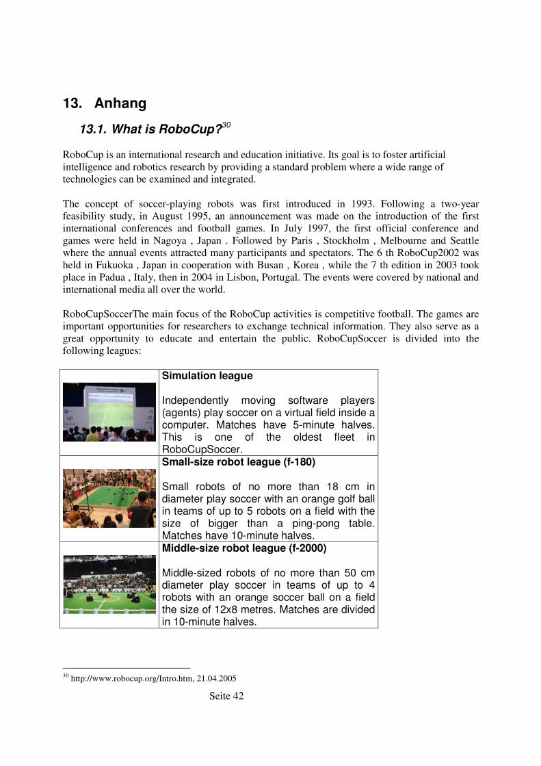
Seite 42
13. Anhang
13.1. What is RoboCup?30
RoboCup is an international research and education initiative. Its goal is to foster artificial intelligence and robotics research by providing a standard problem where a wide range of technologies can be examined and integrated.
The concept of soccer-playing robots was first introduced in 1993. Following a two-year feasibility study, in August 1995, an announcement was made on the introduction of the first international conferences and football games. In July 1997, the first official conference and games were held in Nagoya , Japan . Followed by Paris , Stockholm , Melbourne and Seattle where the annual events attracted many participants and spectators. The 6 th RoboCup2002 was held in Fukuoka , Japan in cooperation with Busan , Korea , while the 7 th edition in 2003 took place in Padua , Italy, then in 2004 in Lisbon, Portugal. The events were covered by national and international media all over the world.
RoboCupSoccerThe main focus of the RoboCup activities is competitive football. The games are important opportunities for researchers to exchange technical information. They also serve as a great opportunity to educate and entertain the public. RoboCupSoccer is divided into the following leagues:
Simulation league
Independently moving software players (agents) play soccer on a virtual field inside a computer. Matches have 5-minute halves. This is one of the oldest fleet in RoboCupSoccer.
Small-size robot league (f-180)
Small robots of no more than 18 cm in diameter play soccer with an orange golf ball in teams of up to 5 robots on a field with the size of bigger than a ping-pong table. Matches have 10-minute halves.
Middle-size robot league (f-2000)
Middle-sized robots of no more than 50 cm diameter play soccer in teams of up to 4 robots with an orange soccer ball on a field the size of 12x8 metres. Matches are divided in 10-minute halves.
30 http://www.robocup.org/Intro.htm, 21.04.2005
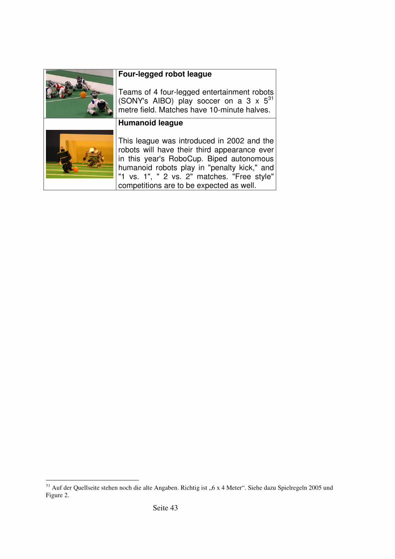
Seite 43
Four-legged robot league
Teams of 4 four-legged entertainment robots (SONY's AIBO) play soccer on a 3 x 531 metre field. Matches have 10-minute halves.
Humanoid league
This league was introduced in 2002 and the robots will have their third appearance ever in this year's RoboCup. Biped autonomous humanoid robots play in "penalty kick," and "1 vs. 1", " 2 vs. 2" matches. "Free style" competitions are to be expected as well.
31 Auf der Quellseite stehen noch die alte Angaben. Richtig ist „6 x 4 Meter“. Siehe dazu Spielregeln 2005 und Figure 2.
Seite 44
13.2. The Variable Lighting Challenge32
This second challenge is intended to encourage teams to increase the robustness of their vision to illumination changes. It is based on a penalty shoot out. The team attempting the challenge places a single blue robot (robot with a blue uniform) on the field. That robot must score as many goals as it can into the yellow goal in three minutes. The team that scores the most goals wins. If two teams score the same number of goals, then the team with the lowest average time to score a goal wins (Note: this is the same as choosing the team who scored their last goal earliest). If no team scores, then the team with the ball closest to the goal at the end of their time wins.
In addition to the single blue robot, two red opponent robots are also placed on the field. Both of these robots are paused, frozen in the UNSW stance. One is placed in a goalie position on one side of the yellow goal. The other is placed in the third of the field nearest the yellow goal, at least 30cm away from the edge. The exact locations of all the robots shall be determined by the referee, and will be the same for all teams. Figure 1 shows one possible situation.
There is a single ball upon the field. Initially it is placed in the center kickoff position. Upon each score, the ball is moved back to the center kickoff position. The robot is not moved by the referee and must make its own way back to the center of the field to reach the ball again. The robot will receive a message from the game controller with its new score. Since the field does not have borders anymore, it is very likely that the ball may be kicked out of the field. In this case, it is placed back at the drop in point (see the document specifying the rules for more details) closest to the point where the ball was kicked out of bounds.
The main challenge in this task is that the illumination shall be different from standard RoboCup lighting. Some additional lights and suitable equipment shall be brought in to supply variable lighting conditions (we envisage variable strength lighting using theatrical lighting equipment). These additional lights shall be white light of deliberately unspecified color temperature. Lights may also be covered to achieve variable lighting conditions.
Before the challenge the referee shall prepare a schedule of illumination changes. This shall include periods of constant illumination, periods of slow change in lighting and periods of rapid changes in lighting. It is envisaged that the additional lighting will be non-uniform across the field and hence the lighting changes will be non-uniform. This lighting schedule, though unknown until right before the challenge, shall be the same for all teams.
Unless otherwise specified, normal penalty shootout rules apply. There will be no penalty for charging the opponent robots. But, it is not allowed to help a robot stop charging and move away from or around another robot.
32 http://www.tzi.de/4legged/pub/Website/Downloads/Challenges2005.pdf, 21.04.2005
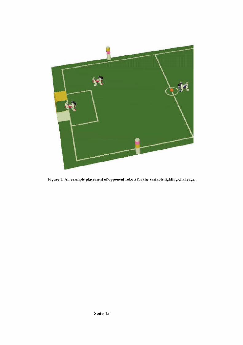
Seite 45
Figure 1: An example placement of opponent robots for the variable lighting challenge.
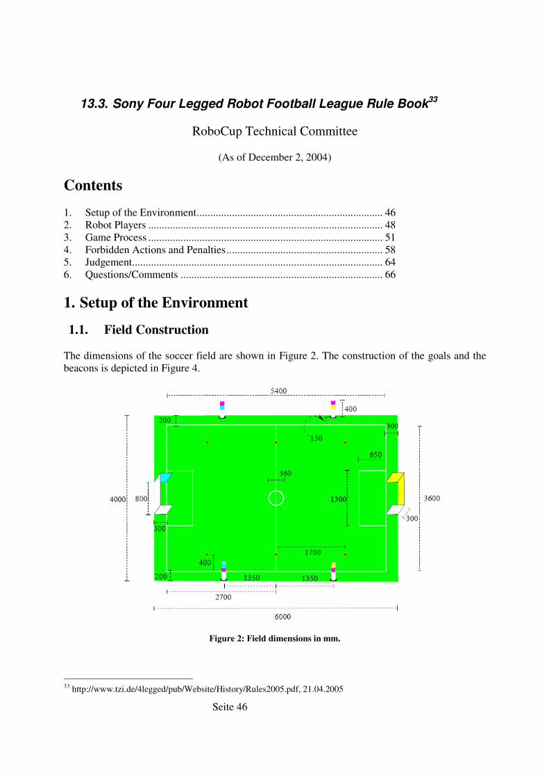
Seite 46
13.3. Sony Four Legged Robot Football League Rule Book33
RoboCup Technical Committee
(As of December 2, 2004)
Contents
1. Setup of the Environment..................................................................... 46 2. Robot Players ....................................................................................... 48 3. Game Process ....................................................................................... 51 4. Forbidden Actions and Penalties.......................................................... 58 5. Judgement............................................................................................. 64 6. Questions/Comments ........................................................................... 66
1. Setup of the Environment
1.1. Field Construction
The dimensions of the soccer field are shown in Figure 2. The construction of the goals and the beacons is depicted in Figure 4.
Figure 2: Field dimensions in mm.
33 http://www.tzi.de/4legged/pub/Website/History/Rules2005.pdf, 21.04.2005
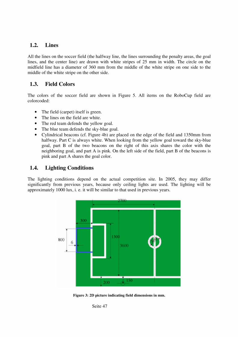
Seite 47
1.2. Lines
All the lines on the soccer field (the halfway line, the lines surrounding the penalty areas, the goal lines, and the center line) are drawn with white stripes of 25 mm in width. The circle on the midfield line has a diameter of 360 mm from the middle of the white stripe on one side to the middle of the white stripe on the other side.
1.3. Field Colors
The colors of the soccer field are shown in Figure 5. All items on the RoboCup field are colorcoded:
• The field (carpet) itself is green. • The lines on the field are white. • The red team defends the yellow goal. • The blue team defends the sky-blue goal. • Cylindrical beacons (cf. Figure 4b) are placed on the edge of the field and 1350mm from
halfway. Part C is always white. When looking from the yellow goal toward the sky-blue goal, part B of the two beacons on the right of this axis shares the color with the neighboring goal, and part A is pink. On the left side of the field, part B of the beacons is pink and part A shares the goal color.
1.4. Lighting Conditions
The lighting conditions depend on the actual competition site. In 2005, they may differ significantly from previous years, because only ceiling lights are used. The lighting will be approximately 1000 lux, i. e. it will be similar to that used in previous years.
Figure 3: 2D picture indicating field dimensions in mm.
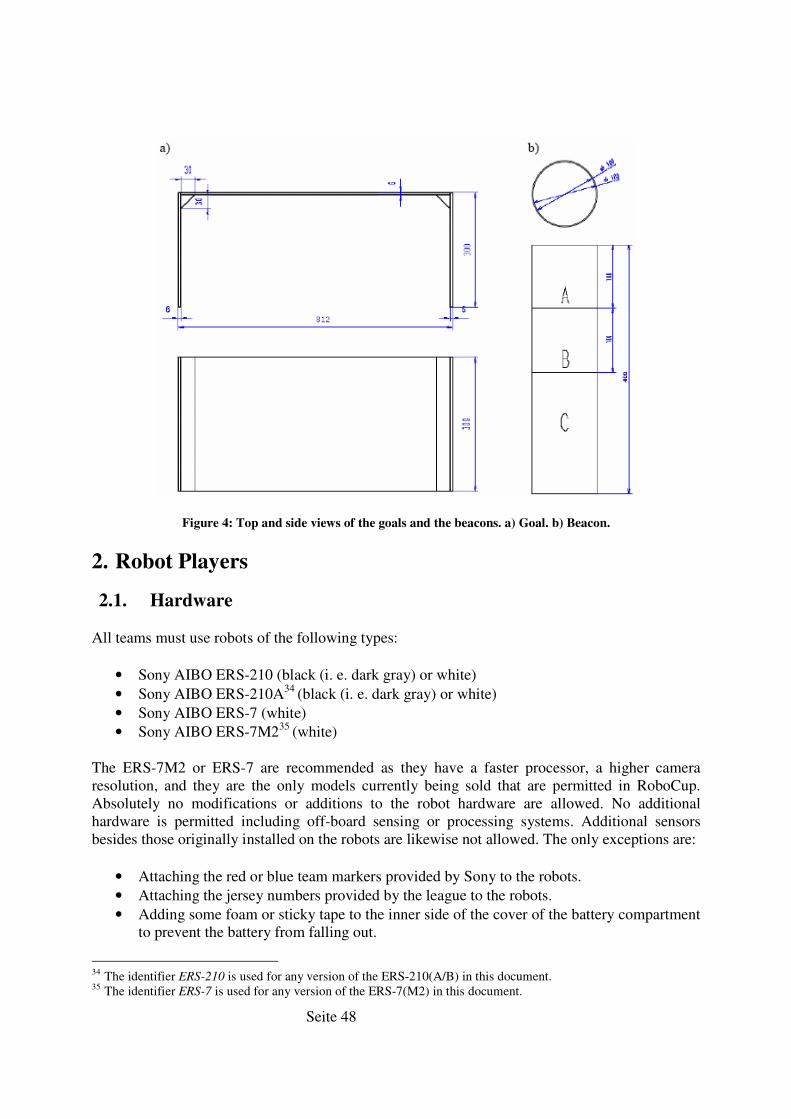
Seite 48
Figure 4: Top and side views of the goals and the beacons. a) Goal. b) Beacon.
2. Robot Players
2.1. Hardware
All teams must use robots of the following types:
• Sony AIBO ERS-210 (black (i. e. dark gray) or white) • Sony AIBO ERS-210A34
(black (i. e. dark gray) or white) • Sony AIBO ERS-7 (white) • Sony AIBO ERS-7M235
(white)
The ERS-7M2 or ERS-7 are recommended as they have a faster processor, a higher camera resolution, and they are the only models currently being sold that are permitted in RoboCup. Absolutely no modifications or additions to the robot hardware are allowed. No additional hardware is permitted including off-board sensing or processing systems. Additional sensors besides those originally installed on the robots are likewise not allowed. The only exceptions are:
• Attaching the red or blue team markers provided by Sony to the robots. • Attaching the jersey numbers provided by the league to the robots. • Adding some foam or sticky tape to the inner side of the cover of the battery compartment
to prevent the battery from falling out.
34 The identifier ERS-210 is used for any version of the ERS-210(A/B) in this document. 35 The identifier ERS-7 is used for any version of the ERS-7(M2) in this document.
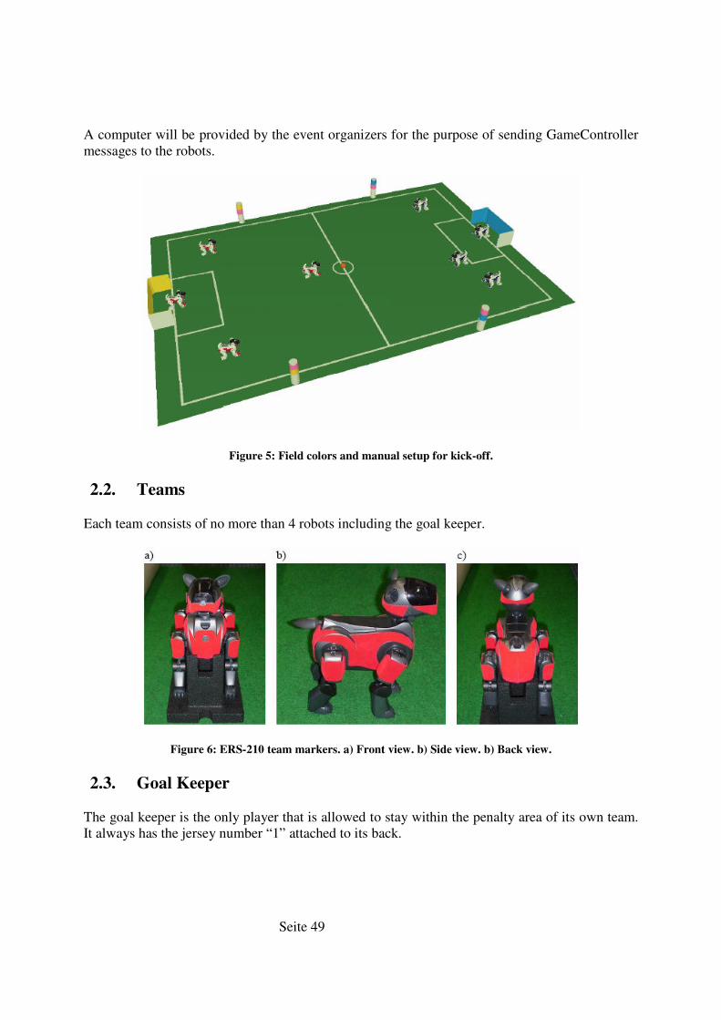
Seite 49
A computer will be provided by the event organizers for the purpose of sending GameController messages to the robots.
Figure 5: Field colors and manual setup for kick-off.
2.2. Teams
Each team consists of no more than 4 robots including the goal keeper.
Figure 6: ERS-210 team markers. a) Front view. b) Side view. b) Back view.
2.3. Goal Keeper
The goal keeper is the only player that is allowed to stay within the penalty area of its own team. It always has the jersey number “1” attached to its back.
Seite 50
2.4. Field Players
The field players are not allowed to enter their own penalty area. The three field players robots have the jersey numbers “2”, “3”, and “4” attached to their backs.
2.5. Team Markers
Red and blue team markers will be provided to each team. All markers must be attached to each robot playing in a game (cf. Figure 6 and Figure 7). As opponent players may try to detect these markers, playing with any markers missing is not allowed.
2.6. Communications
2.6.1. Acoustic Communications
There are no restrictions on communication between the robots using a microphone or a speaker.
2.6.2. Wireless Communications
The only wireless hardware allowed to be used by the teams are the wireless network cards built into the AIBOs, and the access points provided by the event organizers. Or other wireless hardware must be deactivated. A team may be disqualified if one of the team members violates this rule. The MAC-addresses of all AIBOs participating in the competition will be registered. Only these MACaddresses can be reached through the access points provided by the event organizers. In addition, the access points will be secured by different SSIDs and WEP-keys. Two of the access points will be connected to PCs running GameController. A third access point is used for practise. It is connected to a hub with one port for each team. Teams must bring their own ethernet cables.
Each team will get a range of IP-addresses that can be used both for their robots and their computers. The IP-addresses, channels, SSIDs, and WEP-keys of the fields will be announced at the competition site.
Teams can use a bandwidth of up to 500 Kbps of the wireless. This includes any data transferred, namely the actual payload and any protocol overhead created, e. g., by TCP, UDP, or the Game-Controller.
tcpGateway is no longer supported. Teams may still choose to use tcpGateway but it will no longer be a requirement for GameController.
Any form of wireless robot-to-robot communication is allowed, as long as it uses the access points provided by the event organizers (using the so-called ad-hoc mode is prohibited), it does not conflict with TCP/IP or UDP, and the maximum bandwidth allowed for each team is not exceeded. Each team will be assigned a range of 256 IP-addresses that can be used for direct robot-to-robot communication. Each team will also be allocated a limited range of UDP ports on which broadcast will be permitted.

Seite 51
The GameController will use UDP to connect to the robots. The source distribution of the Game-Controller provides the header file RoboCupGameControlData.h that defines all messages sent by the GameController to the robots. They correspond to the robot states described in Section 3.2.
Figure 7: ERS-7 team markers. a) Front view. b) Side view. c) Back view.
Figure 8: Robot states.
The use of remote processing/sensing is prohibited.
3. Game Process
3.1. Structure of the Game
A game consists of three parts, i. e. the first half, a half-time break, and the second half. Each half is 10 minutes. The clock stops during stoppages of play36
(such as kick-offs after goals). The extra time over ten minutes total is referred to as “lost time”. The half-time break is also ten minutes, during this time both teams may change robots, change programs, or anything else that can be done within the time allotted. In the preliminaries a game can finish in a draw as no extra time or penalty shoot-out will follow. In the finals a game that ends in a draw will be followed by
36 This may not be the case during the preliminary games.
Seite 52
five minutes of extra time in which the team that scores first wins (golden goal). There is no break between the second half and the extra time, i. e. the game will simply continue without a kickoff or restart. If no team scored a golden goal, a penalty shoot-out employing sudden death (see Section 3.8) is started after a 5 minute break.
The teams will change the goal defended and color of the team markers during the half-time break.
3.2. Robot States
Robots can be in six different states (cf. Figure 8). If the wireless is available, these states will be set by the GameController. However, as the availability of the wireless cannot be guaranteed, it must also be possible to switch between the states manually. As the assistant referees handle the robots, the button interface must be the same for all teams. However, it cannot be the same for all robot types, because the ERS-210 and the ERS-7 differ in the number of the buttons they have and the sensitivity of these buttons. For most switching between states, the back switch is used on the ERS-210 while the head switch is used on the ERS-7. The only exception is switching from the playing state into the penalized state, which is done with the back switch(es) for both robots, because it would be too complicated to continuously press the switch on a moving head for a longer period of time.
Initial. After booting, the robots are in their initial state. In this state, the button interface for manually setting the team color and whether the team has kick-off is active. The robots are not allowed moving in any fashion besides initially standing up.
ERS-210. The front part of the head switch toggles between the own kick-off and the opponent kick-off, while the top LED displays the current selection (on: own kick-off). The back head switch toggles between the red and blue team color. The team color is displayed by the LED in the robot’s tail during the whole game (orange for the red team, blue for the blue team).
ERS-7. The middle back switch toggles between the own kick-off and the opponent kickoff, while the orange LED around this switch displays the current selection (on: own kick-off). To select the blue team color, press the front back switch, to select the red team color, press the rear back switch. The team color is displayed by the LEDs surrounding these switches, i. e. the red LED is on when the red team color is selected and the blue LED is switched on when the robot is part of the blue team.
Pressing the back switch of an ERS-210 or the head switch of an ERS-7 will switch it to the ready state.
Ready. In this state, the robots walk to their legal kick-off positions (cf. Section 3.5). They remain in this state, until all the robots have reached legal positions and have stopped, or until the head referee decides that there is no significant progress anymore. By
Seite 53
pressing the back switch of an ERS-210 or the head switch of an ERS-7, it will be switched into the set state.
Set. In this state, the robots stop and wait for kick-off (cf. Section 3.5). If they are not at legal positions, they will be placed manually by the assistant referees to the positions shown in Figure 5. They are allowed to move their heads and tails before the game (re)starts but are not allowed moving their legs or locomote in any fashion.
Pressing the back switch of an ERS-210 or the head switch of an ERS-7 will bring them into the playing state, e. g. for kick-off.
Playing. In the playing state, the robots are playing soccer. When at least one of the back switches is pressed for more than one second, the robot is switched into the penalized
state. Please note that this will happen automatically in most cases when an ERS-7 is picked up.
Penalized. A robot is in this state when it has been penalized. It is not allowed moving in any fashion, i. e. also the head has to stop turning. From this state, the robot can be reset to the initial state by pressing the back switch (ERS-210) or the head switch (ERS-7) for more than three seconds. If these switches are pressed shorter than that, the robot is returned into the playing state.
Finished. This state is reached when a half is finished. There is no possibility to reach this state when wireless is not working.
Without the wireless, the procedure after a goal has been scored is a little bit complex. The robots have first to be switched into the penalized state, from which it is possible to return to the initial
state. From there, everything is the same as before the first kick-off.
The team color should be displayed during the whole game. The selection whether the robot’s team has kick-off should be visible in the states initial, ready and set. Both selections should also be visualized if the wireless is working.
3.3. Goal
A goal is achieved when the entire ball (not only the center of the ball) goes over the field-side edge of the goal line, i. e. the ball is completely inside the goal area37. The restart after the goal shall adopt the same rules as the kick-off.
3.4. Applying Penalties
See Section 4.1.
37 The goal line is part of the goal area.
Seite 54
3.5. Kick-off
For kick-off, the robots run through three states: ready, set, and playing. In the ready state, they should walk to their legal kick-off positions. These positions are always located inside their own side of the field. Only two field players of the attacking team can walk to positions between the center line and the middle of their side. They may put their leg(s) on the center circle line, but no leg may be inside the circle line. The other field players (one of attacking team, three of defending team) have to be located behind the middle of their side (none of their legs are allowed to go beyond the middle), but have to stay outside their own penalty area with at least two feet. In contrast, the goal keepers have to stay inside the penalty areas with at least two feet.
If robots collide during the autonomous placement, the “Goalie Pushing” and the “Field Player Pushing” rules are applied, but the penalty is manual placement by the assistant referees.
If all the robots have reached legal positions and have stopped, or if the head referee decides that there is no significant progress anymore, they will be switched into the set state (by the GameController or manually by the assistant referees), in which they must stop walking. Each robot that is not at a legal position at this point in time will be placed manually by the assistant referees to the positions as shown in Figure 5. Robots that are legally positioned will not be moved by the assistant referees unless a manual position is requested by the team leader.
There are extra restrictions on the legal positions of manually positioned robots. The kicking-off robot shall be one robot length away from the center circle, while one robot of the other team shall be just in front of one corner of the penalty area. The other robots shall be on the left and on the right of their own penalty area. As autonomously placed robots are allowed to be much closer to the ball, successful autonomous placement results in a significant advantage over manual placement.
After all robots are at legal positions, the ball is placed on the center point of the center circle by one of the referees.
After the head referee has signaled the kick-off, the robot’s state is switched to playing (again either by the GameController or manually), in which they can actually play soccer.
Note that a goal can never be scored directly from a shot from the kick-off. See Section 4.4 for details.
If the assistant referees have misconfigured the robots (e. g. they set the wrong team color), the kick-off is repeated. In general, goals scored with at least one misconfigured robot on the field are not counted. The time that was played with a wrong configuration is counted as “lost time”, i. e. the half should be lengthened by it.
3.6. Free Kick
None.
Seite 55
3.7. Penalty Kick
A penalty kick is carried out with one attacking robot and one goalie. Other robots should be powered off and stay outside of the field. Teams are allowed to switch to specially designed software for a penalty kick. The attacker has 1 minute in which to score a goal. If the ball leaves the playing area it is not replaced and this penalty kick attempt is deemed unsuccessful.
Standard penalty kicks are taken against the opponent goal (i. e. a blue robot will attack the yellow goal).
The ball is placed 1m from the centre of the field in the direction of the defender’s goal. The attacking robot is positioned 20cm behind the ball. The goalie is placed with its front legs on the goal line and in the centre of the goal. Neither robots shall not move their legs before the penalty kick starts. Movements of the robot’s head and tail are allowed as long as the robot does not locomote. Technically, the robots are in the set state when waiting for the penalty kick to start. The robots are started by setting it into the playing state, which can be done either via the wireless or manually by an assistant referee. The penalty kick ends when the kicker scores the goal, the time expires or the ball leaves the field. The time limit for the kicker is 1 minute after the penalty kick starts. The ball must be in the goal within this time limit in order to count as a goal.
The goalie is not allowed to leave the penalty area (i. e. 3 legs outside) and the attacking robot is not allowed to enter the penalty area (i. e. 3 legs inside the area). If the attacker enters the penalty area then the penalty shot is deemed unsuccessful. If the goalie leaves the penalty area then a goal will be awarded to the attacking team.
All the rules such as “Ball Holding”, ”Goalie Pushing” and others are also applied during the penalty kick. The only exception is the “Illegal Defender” rule, i. e. the penalty shooter is allowed to enter its own penalty area.
3.8. Penalty Kick Shoot-out
A penalty kick shoot-out is used to determine the outcome of a tied game after the extra time. The penalty kick shoot-out is a sudden death contest. Each team selects an attacking robot and a memory stick to be used in the penalty kick shoot-out. They also select a goalie robot and a memory stick for this robot. The memory sticks cannot be changed in between kicks.
In a penalty kick shoot-out, all penalty kicks are taken against the blue goal. This will require each team to do a jersey colour swap on one robot before the penalty shoot-out can start.
The actual procedure is the same as for the normal penalty kick described in Section 3.7. If one team scores within the allotted time and the other does not, the scoring team wins. For the first four attempts, the time limit for the kicker is 1 minute after the penalty kick starts, the same as the normal penalty kick. However, for the fifth attempt it is two minutes. The fifth attempt is timed, i. e. if both teams score, the faster team wins, but only if the faster team is at least two seconds faster than the other team. Otherwise, the timed attempt is repeated.
Seite 56
3.9. Throw-in
If the ball leaves the field it will be replaced using the “boy” model. The game does not stop and the assistant referee will immediately place the ball onto one of six known points on the field.
These six points are shown in red on Figure 2, ‘b’ points are the two points closest to the blue goal, ‘o’ points are those on the halfway line and the ‘y’ points at those closest to the yellow goal.
A ball that last touched a blue robot before leaving the field is replaced at either a ‘b’ or an ‘o’ position on field, as follows:
• A ball kicked out in the blue half of the field is placed on a ‘b’. • A ball kicked out in the yellow half of the field is placed on an ‘o’.
A ball that last touched a red robot before leaving the field is replaced at either a ‘y’ or an ‘o’ position on field, as follows:
• A ball kicked out in the yellow half of the field is placed on a ‘y’. • A ball kicked out in the blue half of the field is placed on an ‘o’.
In all cases, the ball is placed on the appropriately named point closest to where it rolled out, i. e., on the same side that it rolled out on. Balls will be placed ‘near’ the specified point in such a way that no robots are within 50 cm of the ball, i. e. the ball does not have to be placed directly on the “boy” point but as close to the point as possible.
Note that goal lines and side lines are not treated differently. The above rules apply regardless of which line the ball rolled over.
Example 1. The red goalie kicks the ball over its goal line to the right of the yellow goal. The ball is placed on the right ‘y’ point.
Example 2. A blue attacking robot kicks the ball over the goal line to the right of the yellow goal. The ball is placed on the right ‘o’ point.
Example 3. A blue robot kicks the ball over the left sideline just into the yellow half of the field. The ball is replaced on the left ‘o’ point.
Example 4. A blue robot kicks the ball over the left sideline just inside the blue half of the field. The ball is replaced on the left ‘b’ point.
In a case where the referee is unable to determine who last touched to ball, the ball will be replaced at the nearest “boy” position. Balls are deemed to be out based on the team that last touched the ball, irrespective of who actually kicked the ball.
Example. A blue robot kicks the ball but the ball touches a red robot before leaving the field over the right yellow goal line. The ball is regarded as being out off red and therefore is replaced at the right ‘y’ point.
Seite 57
3.10. Game Stuck
3.10.1. Local Game Stuck
In the event of no substantial change in the game state for 30 seconds, the referee shall pick up the robots which are jamming around the ball and move them to the half way line. The referee does not replace the ball. If the ball is accidentally bumped when removing the robots, the ball should be replaced where it was when the game stuck was called. As a special exception, if the goalie is involved in a game stuck situation while having 3 feet on its own half (on half line or closer to goal), the goalie will not be removed from the game stuck situation. In this case, only the other robots involved will be removed.
3.10.2. Global Game Stuck
If no robot touches the ball for 30 seconds, the referee shall stop the game and restart the game from the kick-off formation. The kick-off will be awarded to the team defending the side of the field the ball is on when the game stuck is called.
3.11. Request for Pick-up
Either team may request that one of their players be picked up only for hardware dysfunction and software crashes at any point in the game (called “Request for Pick-up”). It is permitted to change batteries, fix mechanical problems or, if necessary, reboot the robots, but not to change or adjust their program. Any strategic “Request for Pick-up” is not allowed. The head referee will indicate when the robot is no longer affecting play and can be removed from the field by an assistant referee. The robot will be replaced on the half way line after 30 seconds following the normal replacement procedure used after the standard removal penalty (see Section 4.2).
If a robot has been rebooted and the wireless is not working, it is the responsibility of the team members (not the assistant referees) to configure its team color correctly.
3.12. Request for Timeout
At any stoppage of play (after a goal, stuck game, before half, etc.) either team may call a timeout. Each team can call a maximum of 1 timeout per game with a total time totaling no more than 5 minutes. During this time, both teams may change robots, change programs, or anything else that can be done within the time allotted. The timeout ends when the team that called the timeout says they are finished, at which time they must be ready to play. At this time the other team must either be ready to play or call a timeout of its own. The clock stops during timeouts, even during the preliminaries.
After the completion of the timeout, the game resumes with a kick off for the team which did not call the timeout.
If a team is not ready to play at the assigned time for a game, the referee will call the timeout for that team.
Seite 58
3.13. Winner and Rankings
The team which scored more goals than the other is the winner of the match. If the two teams scored the same number of goals, the game will be a draw. The draw will follow the same system defined in Section 3.1. Total (and final) standings will be decided on points as follows (the points will be given based on the result of each game):
Win = 3 pts Draw = 1 Lose = 0 pts
If a team’s obtained points is the same as another team’s after the preliminary round is complete, the following evaluations will be applied in order to qualify the finalists.
1. The points obtained 2. The average difference between goals for and goals against per game 3. The average goals for per game 4. Game result between the teams directly
3.14. Rules for Forfeiting
If a team chooses to forfeit a match then the result will be 10-0 against the team that forfeited. Teams may choose to forfeit games at any stage. Any game with a final score differential greater than 10 points will be considered a forfeit.
4. Forbidden Actions and Penalties
The following actions are forbidden. In general, when a penalty applies, the robot shall be replaced, not the ball. For penalties that are timed, the penalty time is considered to be over whenever the game time stops (for goals, half-time, and game stuck).
4.1. Penalty procedure
When a robot commits a foul, the head referee shall call out the infraction committed, the jersey color of the robot, and the jersey number of the robot. Each robot will be labeled with a jersey number before the game. The penalty for the infraction will be applied immediately by an assistant referee. The assistant referees should perform the actual movement of the robots for the penalty so that the head referee can continue focusing on the game. The operator of the GameController will send the appropriate signal to the robots indicating the infraction committed.
4.2. Standard Removal Penalty
Most infractions in this league result in the removal of the infringing robot from the field of play for a period of time. This process is called the standard removal penalty. When the head referee indicates a foul has been committed that results in the standard removal penalty, the assistant referee closest to the robot will remove the robot immediately from the field of play. The robot should be removed in such a way as to minimize the movement of the other robots and the ball. If
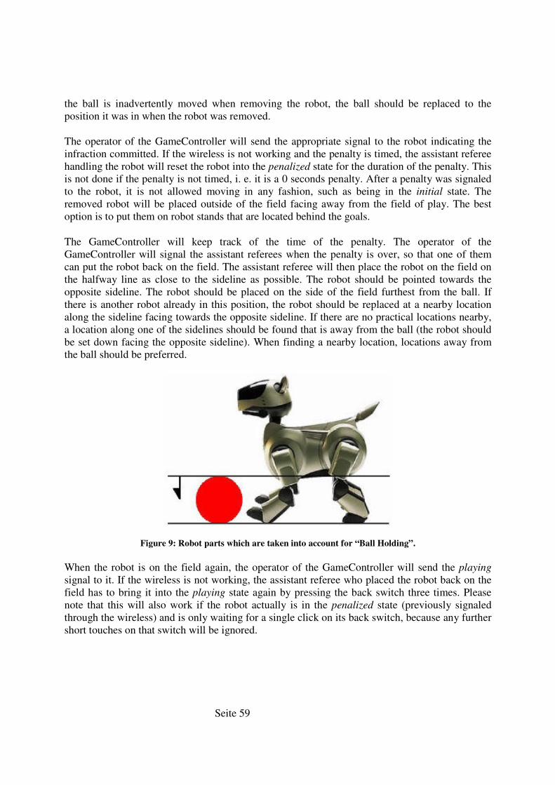
Seite 59
the ball is inadvertently moved when removing the robot, the ball should be replaced to the position it was in when the robot was removed.
The operator of the GameController will send the appropriate signal to the robot indicating the infraction committed. If the wireless is not working and the penalty is timed, the assistant referee handling the robot will reset the robot into the penalized state for the duration of the penalty. This is not done if the penalty is not timed, i. e. it is a 0 seconds penalty. After a penalty was signaled to the robot, it is not allowed moving in any fashion, such as being in the initial state. The removed robot will be placed outside of the field facing away from the field of play. The best option is to put them on robot stands that are located behind the goals.
The GameController will keep track of the time of the penalty. The operator of the GameController will signal the assistant referees when the penalty is over, so that one of them can put the robot back on the field. The assistant referee will then place the robot on the field on the halfway line as close to the sideline as possible. The robot should be pointed towards the opposite sideline. The robot should be placed on the side of the field furthest from the ball. If there is another robot already in this position, the robot should be replaced at a nearby location along the sideline facing towards the opposite sideline. If there are no practical locations nearby, a location along one of the sidelines should be found that is away from the ball (the robot should be set down facing the opposite sideline). When finding a nearby location, locations away from the ball should be preferred.
Figure 9: Robot parts which are taken into account for “Ball Holding”.
When the robot is on the field again, the operator of the GameController will send the playing
signal to it. If the wireless is not working, the assistant referee who placed the robot back on the field has to bring it into the playing state again by pressing the back switch three times. Please note that this will also work if the robot actually is in the penalized state (previously signaled through the wireless) and is only waiting for a single click on its back switch, because any further short touches on that switch will be ignored.
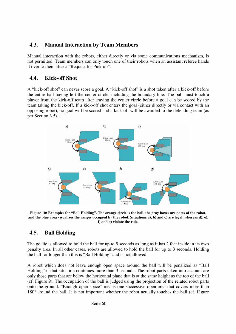
Seite 60
4.3. Manual Interaction by Team Members
Manual interaction with the robots, either directly or via some communications mechanism, is not permitted. Team members can only touch one of their robots when an assistant referee hands it over to them after a “Request for Pick-up”.
4.4. Kick-off Shot
A “kick-off shot” can never score a goal. A “kick-off shot” is a shot taken after a kick-off before the entire ball having left the center circle, including the boundary line. The ball must touch a player from the kick-off team after leaving the center circle before a goal can be scored by the team taking the kick-off. If a kick-off shot enters the goal (either directly or via contact with an opposing robot), no goal will be scored and a kick-off will be awarded to the defending team (as per Section 3.5).
Figure 10: Examples for “Ball Holding”. The orange circle is the ball, the gray boxes are parts of the robot,
and the blue area visualizes the ranges occupied by the robot. Situations a), b) and c) are legal, whereas d), e),
f) and g) violate the rule.
4.5. Ball Holding
The goalie is allowed to hold the ball for up to 5 seconds as long as it has 2 feet inside in its own penalty area. In all other cases, robots are allowed to hold the ball for up to 3 seconds. Holding the ball for longer than this is “Ball Holding” and is not allowed.
A robot which does not leave enough open space around the ball will be penalized as “Ball Holding” if that situation continues more than 3 seconds. The robot parts taken into account are only those parts that are below the horizontal plane that is at the same height as the top of the ball (cf. Figure 9). The occupation of the ball is judged using the projection of the related robot parts onto the ground. “Enough open space” means one successive open area that covers more than 180° around the ball. It is not important whether the robot actually touches the ball (cf. Figure
Seite 61
10a, b vs. Figure 10d, e). If the chin of the robot touches the ball, that part is also lower than the top the ball, and therefore must also be taken into account (cf. Figure 10c, f, g).
Intentional continual holding is prohibited even if each individual holding time does not continue for up to the time limit. In this case, the continual holding is regarded as a continuous hold from the very beginning and the holding rule is strictly applied. The violation of this rule will result in having the penalized robot removed from the field for 30 seconds as per the standard removal penalty (see Section 4.2 for details). In case of a violation by the goal keeper, the robot will be removed for 0 seconds as per the standard removal penalty, i. e. he will be placed on the halfway line immediately (no need to be kept outside of the field). The ball should be removed from the possession of the robot and placed where the foul occurred. If the robot that held the ball has moved the ball before the robot can be removed, the ball shall be replaced where the foul occurred.
Example. A robot holds the ball and before the referees can remove the robot, it shoots the ball into the goal. The goal will not be counted and the ball will be replaced where the robot held the ball.
4.6. Goalie Pushing
When the goalie is in its own penalty area (2 feet on or inside line), no attacker may be in contact with the goalie for more than 3 seconds or be pushing the goalie indirectly through the ball for more than 3 seconds. If two attacking robots are in simultaneously in contact with the goalie then the second attacking robot will be removed immediately and penalised for 30 seconds.
Successive short pushes shall be counted as a single push even if each individual contact does not continue for three seconds. A robot should obviously back off for at least as long as it pushed for the three second clock to reset. When violating this rule the attacker will be removed for 30 seconds as per the standard removal penalty (see Section 4.2).
If a goal is scored by an action performed after the 3 seconds of contact are over (or by a second robot that is touching the goalie), but before the robot can be removed, the ball and the robots involved in that action (the goalie, other robots, but not the penalized robot) shall be replaced where they were when the foul occurred.
Example 1. An attacker that has pushed the goalie shoots a goal after the violation but before it was removed. In that case, the goalie and the ball are replaced to the locations they were when the violation happened, and the goal is not counted.
Example 2. A second attacker scored a goal after the violation but before the pushing robot was removed. In that case, the goalie, the second attacker, and the ball are replaced to their original locations when the violation happened, and the goal is not counted. This is necessary, because the pushing robot prevented the goal keeper from defending its goal.
Example 3. An attacker that is currently pushing a goalie shoots a goal. If there has not yet been 3 seconds of contact between the attacker and the goalie, then the goal is allowed.
Seite 62
4.7. Field Player Pushing
Any robot pushing another robot for more than 3 seconds will be removed from play for 30 seconds as per the standard removal penalty (see Section 4.2). The closest robot (including the goal keeper) to the ball on each team, if it is within 2 dog-lengths of the ball, cannot be called for pushing. If a robot is standing still it cannot be called for pushing. If two moving robots are charging into each other then both robots are removed. The goalie cannot be called for pushing as long as it is within its penalty area at least with two legs.
Example 1. If two robots of different teams are fighting for the ball and a third robot touches one of them, it will be removed.
Example 2. If two robots of the same team are—for some reason—fighting for the ball, the robot that is further away from the ball will be removed.
Example 3. If two robots are pushing each other without a ball in the vicinity, they are both removed. If only one of them is moving, only the moving robot is removed.
4.8. Damage to the Field/Robots/Ball
A robot that knocks over one of the beacons will be removed for 30 seconds as per the standard removal penalty (see Section 4.2). A robot that damages the field and/or other robots will be removed from the field for the remainder of the game. Similarly a robot that poses a threat to the spectator’s safety will also be removed. In such a case, a normal penalty kick will be awarded to the opposing team (cf. Section 3.7).
4.9. Leaving the Field
A robot that leaves the 4x6m carpeted area will be removed for 30 seconds as per the standard removal penalty (see Section 4.2). i. e. a robot may leave the 3.6x5.4m playing field but must stay within the 4x6m area.
4.10. Illegal Defender
Only the goalie can be within its team’s penalty area. Having three legs inside the penalty area is the definition of being in the penalty area and that situation is not allowed for defending field players. When other defending robots enter the area, they will be removed for 30 seconds as per the standard removal penalty (see Section 4.2). This is called the “Illegal Defender Rule”. This rule will be applied even if the goalie is outside of the penalty area, but not if an operational defender is pushed into the penalty area by an opponent.
If an illegal defender kicks an own goal, the goal is scored for the opponent.
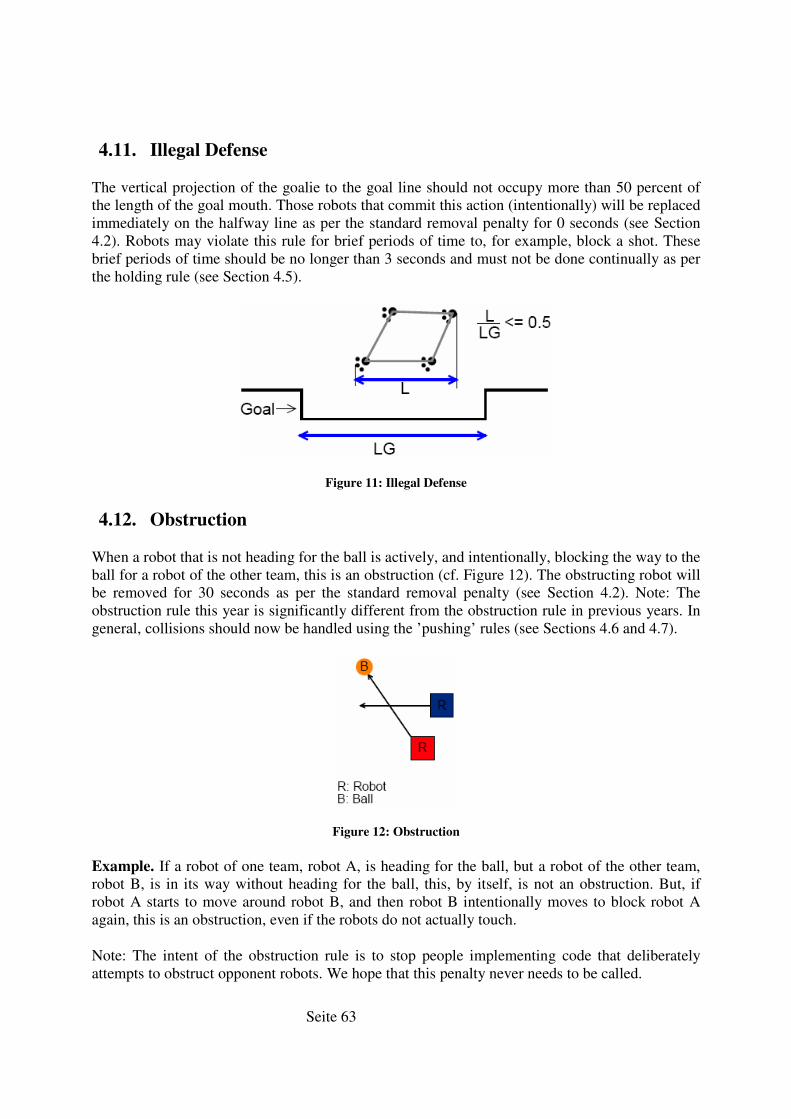
Seite 63
4.11. Illegal Defense
The vertical projection of the goalie to the goal line should not occupy more than 50 percent of the length of the goal mouth. Those robots that commit this action (intentionally) will be replaced immediately on the halfway line as per the standard removal penalty for 0 seconds (see Section 4.2). Robots may violate this rule for brief periods of time to, for example, block a shot. These brief periods of time should be no longer than 3 seconds and must not be done continually as per the holding rule (see Section 4.5).
Figure 11: Illegal Defense
4.12. Obstruction
When a robot that is not heading for the ball is actively, and intentionally, blocking the way to the ball for a robot of the other team, this is an obstruction (cf. Figure 12). The obstructing robot will be removed for 30 seconds as per the standard removal penalty (see Section 4.2). Note: The obstruction rule this year is significantly different from the obstruction rule in previous years. In general, collisions should now be handled using the ’pushing’ rules (see Sections 4.6 and 4.7).
Figure 12: Obstruction
Example. If a robot of one team, robot A, is heading for the ball, but a robot of the other team, robot B, is in its way without heading for the ball, this, by itself, is not an obstruction. But, if robot A starts to move around robot B, and then robot B intentionally moves to block robot A again, this is an obstruction, even if the robots do not actually touch.
Note: The intent of the obstruction rule is to stop people implementing code that deliberately attempts to obstruct opponent robots. We hope that this penalty never needs to be called.
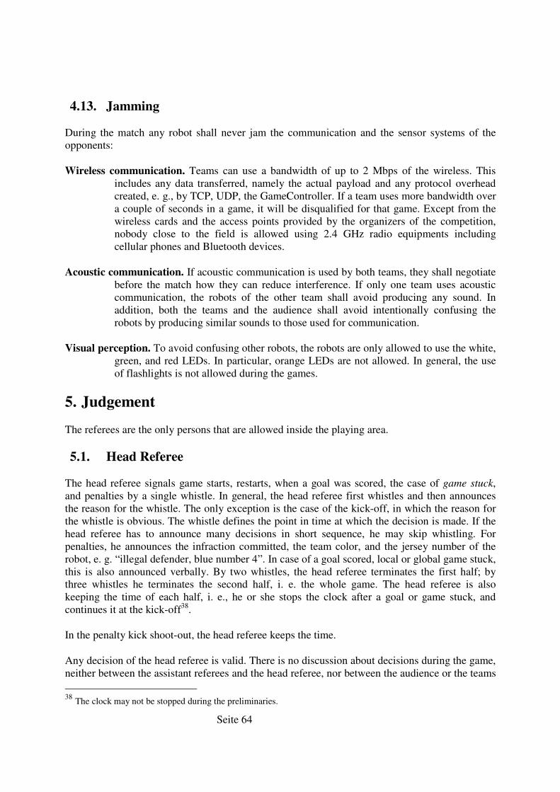
Seite 64
4.13. Jamming
During the match any robot shall never jam the communication and the sensor systems of the opponents:
Wireless communication. Teams can use a bandwidth of up to 2 Mbps of the wireless. This includes any data transferred, namely the actual payload and any protocol overhead created, e. g., by TCP, UDP, the GameController. If a team uses more bandwidth over a couple of seconds in a game, it will be disqualified for that game. Except from the wireless cards and the access points provided by the organizers of the competition, nobody close to the field is allowed using 2.4 GHz radio equipments including cellular phones and Bluetooth devices.
Acoustic communication. If acoustic communication is used by both teams, they shall negotiate before the match how they can reduce interference. If only one team uses acoustic communication, the robots of the other team shall avoid producing any sound. In addition, both the teams and the audience shall avoid intentionally confusing the robots by producing similar sounds to those used for communication.
Visual perception. To avoid confusing other robots, the robots are only allowed to use the white, green, and red LEDs. In particular, orange LEDs are not allowed. In general, the use of flashlights is not allowed during the games.
5. Judgement
The referees are the only persons that are allowed inside the playing area.
5.1. Head Referee
The head referee signals game starts, restarts, when a goal was scored, the case of game stuck, and penalties by a single whistle. In general, the head referee first whistles and then announces the reason for the whistle. The only exception is the case of the kick-off, in which the reason for the whistle is obvious. The whistle defines the point in time at which the decision is made. If the head referee has to announce many decisions in short sequence, he may skip whistling. For penalties, he announces the infraction committed, the team color, and the jersey number of the robot, e. g. “illegal defender, blue number 4”. In case of a goal scored, local or global game stuck, this is also announced verbally. By two whistles, the head referee terminates the first half; by three whistles he terminates the second half, i. e. the whole game. The head referee is also keeping the time of each half, i. e., he or she stops the clock after a goal or game stuck, and continues it at the kick-off38.
In the penalty kick shoot-out, the head referee keeps the time.
Any decision of the head referee is valid. There is no discussion about decisions during the game, neither between the assistant referees and the head referee, nor between the audience or the teams
38 The clock may not be stopped during the preliminaries.
Seite 65
and the head referee. Neither the teams, nor the audience can have any influence on the positions the head referee selects for the penalty kick shoot-out.
5.2. Assistant Referees
The two assistant referees handle the robots. They start them if the wireless is not working, they move them manually to legal kick-off positions, they take them out when the robots are penalized, and they put them in again. If a team requests picking up a robot, an assistant referee will pick it up and give it to one of the team members. An assistant referee will also put the robot back on the field. In addition, the assistant referees can indicate violations against the rules committed by robots to the head referee, so that the head referee can decide whether to penalize a certain robot or not.
5.3. Operator of the GameController
The operator of the GameController sits at a PC outside the playing area. He or she will signal any change in the game state to the robots via the wireless as they are announced by the head referee.
He or she will also inform the assistant referees when a timed penalty is over and a robot has to be placed back on the field.
5.4. Selection of the Referees
At least in the preliminaries, the games will be refereed by members of teams from a different Round-Robin group. Each team has to referee a number of these games. For each of the games, it can either provide the head referee and the operator of the GameController, or the two assistant referees. These persons must have good knowledge of the rules as applied in the tournament, and the operator of the GameController must be experienced in using that software. The persons should be selected among the more senior members of a team, and preferably have prior experience with games in the RoboCup Four-Legged Robot league.
Referees for playoff games will need to be certified (i. e. deemed fit to referee) by at least half the teams in the playoffs. Unless they have no eligible referees, each team in the playoffs shall supply at least one referee for the playoffs. For a particular game, each of the teams playing shall be able to veto one and only one eligible referee with no reason required.
5.5. Referees During the Match
The head referee and the assistant referees should wear black or white clothing/shoes and avoid reserved colors for the ball, the goals, and player markings in their clothing. They may enter the field in particular situations, e. g., to reposition the robots when applying a or stuck. They should avoid interfering with the robots as much as possible.

Seite 66
6. Questions/Comments
Questions or comments on these rules should be mailed to legged [email protected]
Seite 67
14. Eidesstattliche Erklärung
Ich versichere, dass ich die vorstehende Arbeit selbstständig und ohne fremde Hilfe angefertigt und mich anderer als der im beigefügten Verzeichnis angegebenen Hilfsmittel nicht bedient habe. Alle Stellen, die wörtlich oder sinngemäß aus Veröffentlichungen entnommen wurden, sind als solche kenntlich gemacht.
Hamburg, 9. September 2005
Valerij Krichevskyi
Ich bin mit einer Einstellung in den Bestand der Bibliothek des Fachbereiches einverstanden.
Hamburg, 9. September 2005
Valerij Krichevskyi
Lernsystem für die Verhaltenssteuerung in derRoboCup Four Legged League
Implementierung eines lernfähigen Systems für die Verwendunginnerhalb der XABSL2-Beschreibung des German Team-Codes
Jonas Reese([email protected])
Eine Projektarbeit im Rahmen des Projekts"RoboCups - Robotersysteme in der SONY-LeggedLiga"
SOSE 2004/WS 2005 am Arbeitsbereich TISdes Fachbereichs Informatik, Universität Hamburg.
Projektleitung: Dipl.-Inform. Birgit Koch, Prof. Dr.-Ing. D.P.F. Möller
19. März 2005
Inhaltsverzeichnis
1 Einführung 11.1 Übersicht über die Architektur des German Team Codes . . . . . 11.2 BehaviorControl - die Verhaltenskontrolle . . . . . . . . . . . . 21.3 Die Extended Agent Behavior Speci�cation Language (XABSL) . 21.4 Wo dieses Projekt ansetzt . . . . . . . . . . . . . . . . . . . . . . 31.5 Begri�sde�nitionen . . . . . . . . . . . . . . . . . . . . . . . . . . 3
2 Das Lernsystem 42.1 Repräsentation von lernbezogenen Erfahrungswerten . . . . . . . 4
2.1.1 Die Klasse Experience . . . . . . . . . . . . . . . . . . . 72.1.2 Die Klasse ExperienceBase . . . . . . . . . . . . . . . . . 7
2.2 Das Lernmodul . . . . . . . . . . . . . . . . . . . . . . . . . . . . 82.2.1 Aufgaben . . . . . . . . . . . . . . . . . . . . . . . . . . . 82.2.2 Eine Standardlösung für das Lernmodul . . . . . . . . . . 9
2.2.2.1 Sammeln von bewertungsrelevanten Informationen 92.2.2.2 Bewertung von lernbezogenen Erfahrungen . . . 10
2.3 Lernsymbole . . . . . . . . . . . . . . . . . . . . . . . . . . . . . 112.3.1 Aufgaben . . . . . . . . . . . . . . . . . . . . . . . . . . . 112.3.2 Aufbau der logischen Bezeichner . . . . . . . . . . . . . . 11
2.4 Der Experience Editor für RobotControl . . . . . . . . . . . . . . 122.4.1 Funktion . . . . . . . . . . . . . . . . . . . . . . . . . . . 122.4.2 Erstellen einer Kon�guration . . . . . . . . . . . . . . . . 122.4.3 Editieren der Erfahrungsdatenbasis . . . . . . . . . . . . . 13
3 Vorgehensweise zum Hinzufügen eines neuen Erfahrungstyps 153.1 Registrieren des Erfahrungstyps . . . . . . . . . . . . . . . . . . . 153.2 Festlegen des Wertebereiches und des Standardwertes . . . . . . 163.3 Registrieren des XABSL-Eingabesymbols . . . . . . . . . . . . . 163.4 Anpassung der Verhaltensbeschreibung . . . . . . . . . . . . . . . 16
4 Durchführung des Lernprozesses 18
5 Fazit und Bewertung 19
1
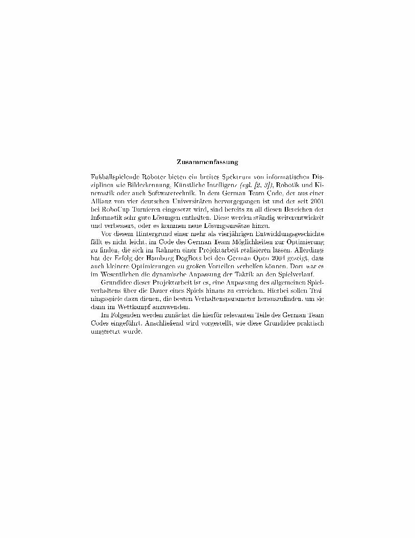
Zusammenfassung
Fuÿballspielende Roboter bieten ein breites Spektrum von informatischen Dis-ziplinen wie Bilderkennung, Künstliche Intelligenz (vgl. [2, 3]), Robotik und Ki-nematik oder auch Softwaretechnik. In dem German Team Code, der aus einerAllianz von vier deutschen Universitäten hervorgegangen ist und der seit 2001bei RoboCup-Turnieren eingesetzt wird, sind bereits zu all diesen Bereichen derInformatik sehr gute Lösungen enthalten. Diese werden ständig weiterentwickeltund verbessert, oder es kommen neue Lösungsansätze hinzu.
Vor diesem Hintergrund einer mehr als vierjährigen Entwicklungsgeschichtefällt es nicht leicht, im Code des German Team Möglichkeiten zur Optimierungzu �nden, die sich im Rahmen einer Projektarbeit realisieren lassen. Allerdingshat der Erfolg der Hamburg DogBots bei den German Open 2004 gezeigt, dassauch kleinere Optimierungen zu groÿen Vorteilen verhelfen können. Dort war esim Wesentlichen die dynamische Anpassung der Taktik an den Spielverlauf.
Grundidee dieser Projektarbeit ist es, eine Anpassung des allgemeinen Spiel-verhaltens über die Dauer eines Spiels hinaus zu erreichen. Hierbei sollen Trai-ningsspiele dazu dienen, die besten Verhaltensparameter herauszu�nden, um siedann im Wettkampf anzuwenden.
Im Folgenden werden zunächst die hierfür relevanten Teile des German TeamCodes eingeführt. Anschlieÿend wird vorgestellt, wie diese Grundidee praktischumgesetzt wurde.

Kapitel 1
Einführung
1.1 Übersicht über die Architektur des GermanTeam Codes
Ein wichtiges Merkmal des German Team Codes ist die Abstraktion von der Ziel-plattform. Enthalten sind in der aktuellen Version Implementationen für Ape-rios - also das Aibo-Betriebssystem - und die Simulatorsoftware für Windows-Betriebssysteme. Erreicht wird diese Plattformunabhängigkeit durch Prozesse,die das Bindeglied zwischen System und Anwendung bilden (vgl. [3]). Diese Pro-zesse werden von dem plattformabhängigen Prozessrahmenwerk zyklisch aufge-rufen und führen die ihnen zugeordneten Aufgaben plattformunabhängig aus,da sie nur auf im Code enthaltene Datenstrukturen zugreifen, die dann vom Pro-zessrahmenwerk interpretiert werden. Im Wesentlichen werden zwei Aufgaben-gebiete unterteilt: Motion und Cognition. Der Motion-Prozess ist für den Bewe-gungsapparat zuständig, während Cognition alle übrigen Aufgaben wie Bild-verarbeitung, Selbstlokalisation, Sensordatenerfassung und -verarbeitung undVerhaltenskontrolle übernimmt. Es existieren weitere Prozesse für Logging- undDebuggingfunktionalitäten.
Die einzelnen Aufgaben eines Prozesses werden in Modulen gekapselt. Hier-durch wird erreicht, dass der Quellcode klar nach Aufgaben strukturiert undmodularisiert werden kann. Auÿerdem erleichtert diese Herangehensweise denAustausch von verschiedenen Lösungen für einzelne Aufgaben.
Prozesse kommunizieren über Nachrichtenaustausch, während die Kommu-nikation zwischen Modulen eines Prozesses über einen gemeinsamen Datenspei-cher im Prozess oder über Nachrichtenaustausch statt�nden kann. Zwar könnenProzesse nebenläu�g ausgeführt werden, Module hingegen werden innerhalb ei-nes Prozesses nacheinander ausgeführt, so dass keine Kon�ikte durch nebenläu-�gen Zugri� auf den gemeinsamen Datenspeicher auftreten.
1
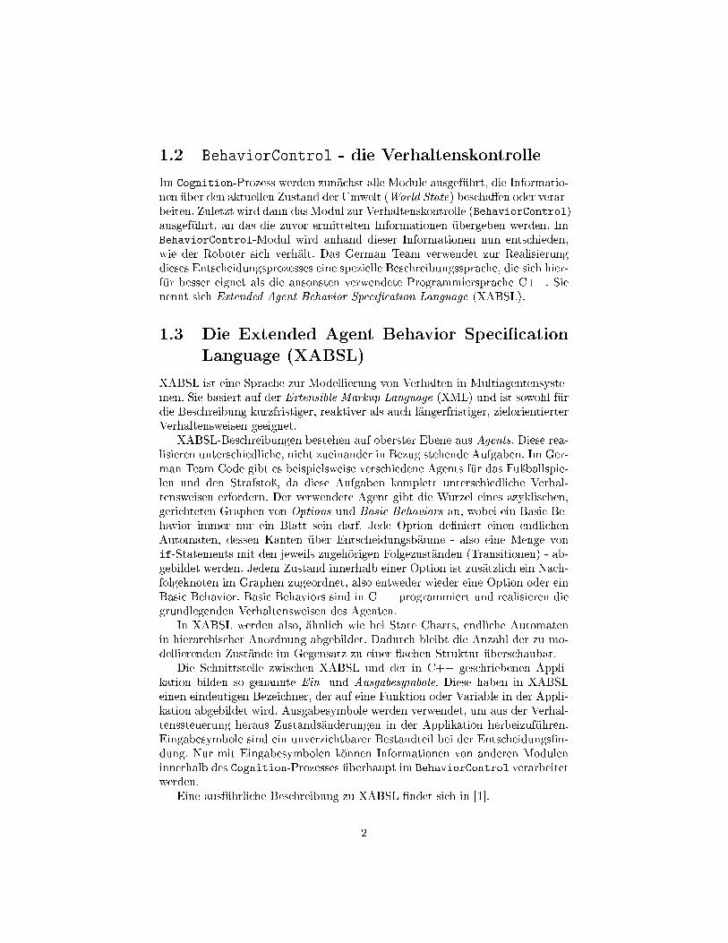
1.2 BehaviorControl - die VerhaltenskontrolleIm Cognition-Prozess werden zunächst alle Module ausgeführt, die Informatio-nen über den aktuellen Zustand der Umwelt (World State) bescha�en oder verar-beiten. Zuletzt wird dann das Modul zur Verhaltenskontrolle (BehaviorControl)ausgeführt, an das die zuvor ermittelten Informationen übergeben werden. ImBehaviorControl-Modul wird anhand dieser Informationen nun entschieden,wie der Roboter sich verhält. Das German Team verwendet zur Realisierungdieses Entscheidungsprozesses eine spezielle Beschreibungssprache, die sich hier-für besser eignet als die ansonsten verwendete Programmiersprache C++. Sienennt sich Extended Agent Behavior Speci�cation Language (XABSL).
1.3 Die Extended Agent Behavior Speci�cationLanguage (XABSL)
XABSL ist eine Sprache zur Modellierung von Verhalten in Multiagentensyste-men. Sie basiert auf der Extensible Markup Language (XML) und ist sowohl fürdie Beschreibung kurzfristiger, reaktiver als auch längerfristiger, zielorientierterVerhaltensweisen geeignet.
XABSL-Beschreibungen bestehen auf oberster Ebene aus Agents. Diese rea-lisieren unterschiedliche, nicht zueinander in Bezug stehende Aufgaben. Im Ger-man Team Code gibt es beispielsweise verschiedene Agents für das Fuÿballspie-len und den Strafstoÿ, da diese Aufgaben komplett unterschiedliche Verhal-tensweisen erfordern. Der verwendete Agent gibt die Wurzel eines azyklischen,gerichteten Graphen von Options und Basic Behaviors an, wobei ein Basic Be-havior immer nur ein Blatt sein darf. Jede Option de�niert einen endlichenAutomaten, dessen Kanten über Entscheidungsbäume - also eine Menge vonif-Statements mit den jeweils zugehörigen Folgezuständen (Transitionen) - ab-gebildet werden. Jedem Zustand innerhalb einer Option ist zusätzlich ein Nach-folgeknoten im Graphen zugeordnet, also entweder wieder eine Option oder einBasic Behavior. Basic Behaviors sind in C++ programmiert und realisieren diegrundlegenden Verhaltensweisen des Agenten.
In XABSL werden also, ähnlich wie bei State Charts, endliche Automatenin hierarchischer Anordnung abgebildet. Dadurch bleibt die Anzahl der zu mo-dellierenden Zustände im Gegensatz zu einer �achen Struktur überschaubar.
Die Schnittstelle zwischen XABSL und der in C++ geschriebenen Appli-kation bilden so genannte Ein- und Ausgabesymbole. Diese haben in XABSLeinen eindeutigen Bezeichner, der auf eine Funktion oder Variable in der Appli-kation abgebildet wird. Ausgabesymbole werden verwendet, um aus der Verhal-tenssteuerung heraus Zustandsänderungen in der Applikation herbeizuführen.Eingabesymbole sind ein unverzichtbarer Bestandteil bei der Entscheidungs�n-dung. Nur mit Eingabesymbolen können Informationen von anderen Moduleninnerhalb des Cognition-Prozesses überhaupt im BehaviorControl verarbeitetwerden.
Eine ausführliche Beschreibung zu XABSL �ndet sich in [1].
2
1.4 Wo dieses Projekt ansetztDie Verhaltensbeschreibung des German Team lässt sich vereinfacht als hier-archischer Entscheidungsbaum bezeichnen, an dessen Blättern sich die BasicBehaviors be�nden, also die programmatisch realisierten grundlegenden Verhal-tensweisen und Fähigkeiten des Roboters (siehe [1]). Innerhalb dieses Entschei-dungsbaumes werden immer wieder Grenzwerte verwendet, also Werte, die aus-schlaggebend dafür sind, ob nun die eine oder die andere Entscheidung getro�enwird. Diese Grenzwerte entstehen in der Regel durch Abschätzungen seitens derEntwickler, oder es sind Erfahrungswerte, die durch Testen gewonnen wurden.
Warum aber nicht genau diese Aufgabe dem Roboter überlassen? Wenn manvoraussetzt, dass zumindest in einigen dieser Grenzwerte Optimierungspotenzialsteckt, so macht es Sinn, den Roboter selbst Erfahrungswerte ausprobieren undbewerten zu lassen, um dann, wenn es darauf ankommt (im Turnier), die bestenWerte zu verwenden.
1.5 Begri�sde�nitionenWie bereits erwähnt, wird also ein Teil der konstanten Grenzwerte, die bei derEntscheidungs�ndung relevant sind, in Variablen umgewandelt. Anschlieÿendsoll der Roboter selbst durch Ausprobieren und Bewerten den besten Grenz-wert heraus�nden. Jeder dieser zu testenden Grenzwerte wird im FolgendenErfahrungswert genannt. Erfahrungstyp hingegen bezeichnet eine Klasse gleich-artiger Grenzwerte. Ein Tupel, bestehend aus einem Erfahrungswert und einemErfahrungstyp wird einfach Erfahrung genannt. Einer Erfahrung wird dann imLaufe der Zeit eine Bewertung zugeordnet, die die Qualität der Erfahrung wi-derspiegelt. Eine Menge von Erfahrungen ist eine Erfahrungsdatenbasis oderErfahrungsbasis.
3
Kapitel 2
Das Lernsystem
In diesem Kapitel werden Konzept, Aufbau und Implementation des Lernsys-tems ausführlich behandelt. Den Kern dieses Projekts bilden drei Komponenten(vgl. [5]), deren funktionale Beziehungen zueinander und zu den beiden wich-tigsten Prozessen Cognition und Motion (siehe Abschnitt 1.1) - in Abbildung2.1 dargestellt sind:
• Die Erfahrungsbasis (in Abbildung 2.1 grün hinterlegt),
• das Lernmodul (in Abbildung 2.1 gelb hinterlegt) und
• die Lernsymbole (rot hinterlegt).
Das UML-Diagramm in Abbildung 2.2 zeigt eine Übersicht über die Klassen desLernsystems, deren statische Assoziationen und Vererbungshierarchien, sowiedie funktionale Zugehörigkeit (anhand der Farbgebung, vergleiche Abbildung2.1). Anmerkung: Weder Attribute noch Operationen der Klassen sind vollstän-dig; es wurden jeweils nur die wichtigsten Attribute und Operationen in dasDiagramm übernommen.
Nicht in den Abbildungen enthalten ist der Experience Editor, der in dieRobotControl -Software integriert wurde und dem Benutzer ermöglicht, über einegraphische Benutzerschnittstelle das Lernsystem zu administrieren. Von demExperience Editor werden nur die �für den Benutzer sichtbaren� Teile am Endedieses Kapitels vorgestellt.
2.1 Repräsentation von lernbezogenen Erfahrungs-werten
Erfahrungen müssen nicht nur zur Laufzeit in einer geeigneten Datenstruk-tur organisiert werden, sondern auch persistent gespeichert werden können, da
4
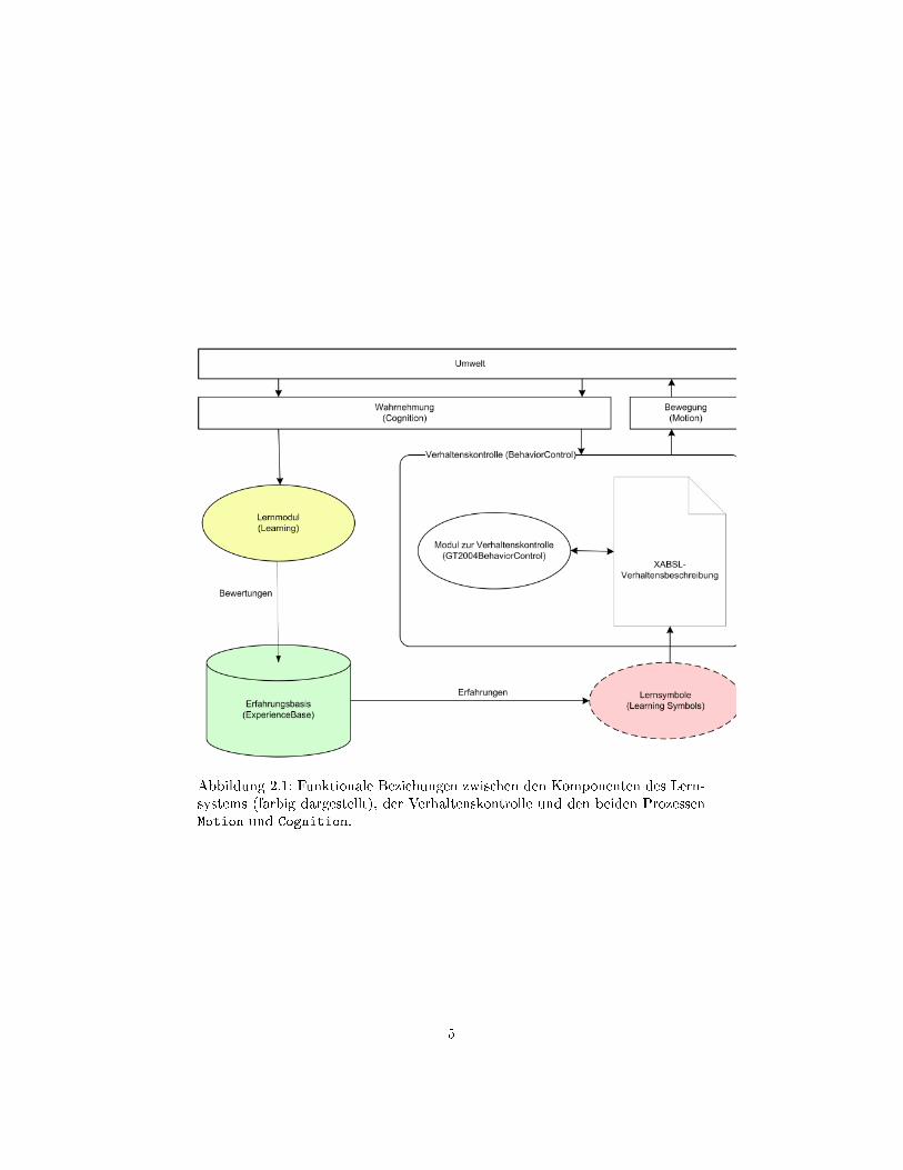
Abbildung 2.1: Funktionale Beziehungen zwischen den Komponenten des Lern-systems (farbig dargestellt), der Verhaltenskontrolle und den beiden ProzessenMotion und Cognition.
5
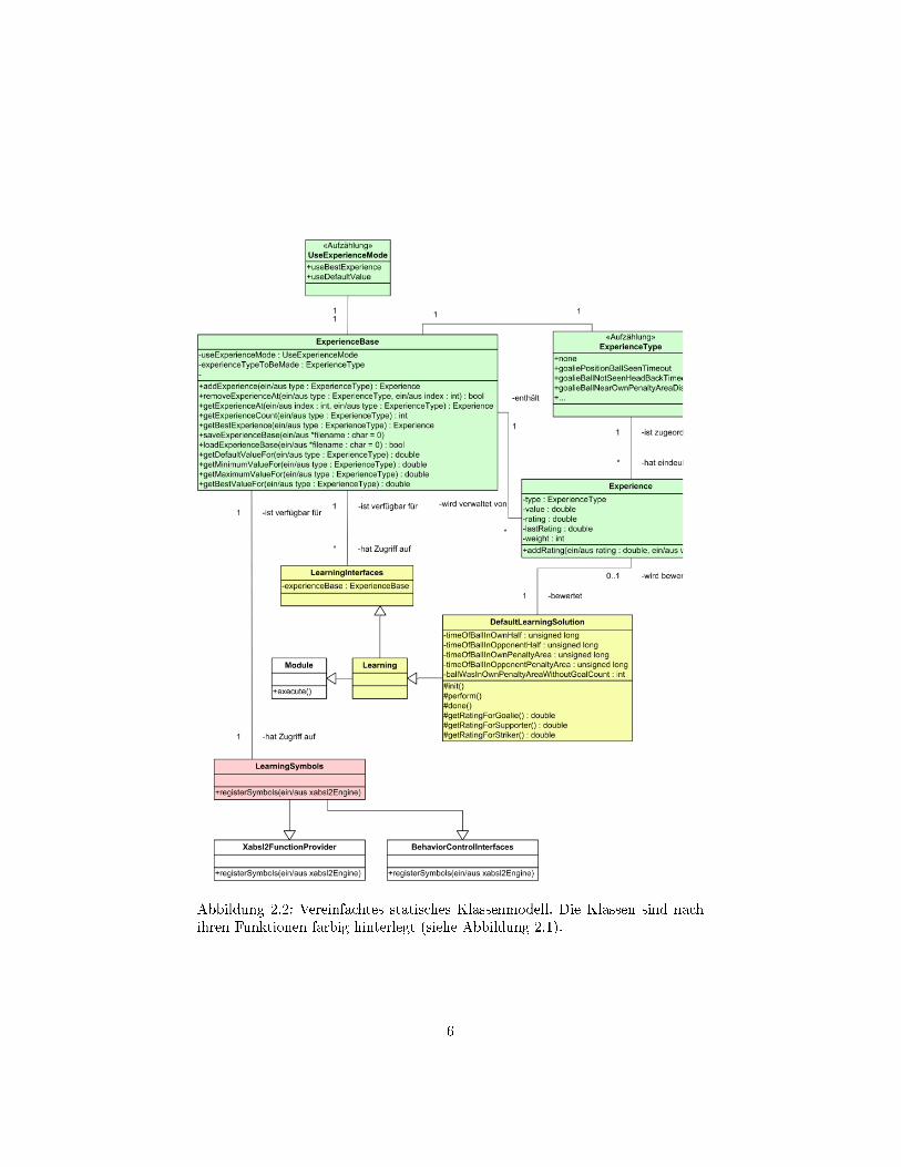
Abbildung 2.2: Vereinfachtes statisches Klassenmodell. Die Klassen sind nachihren Funktionen farbig hinterlegt (siehe Abbildung 2.1).
6
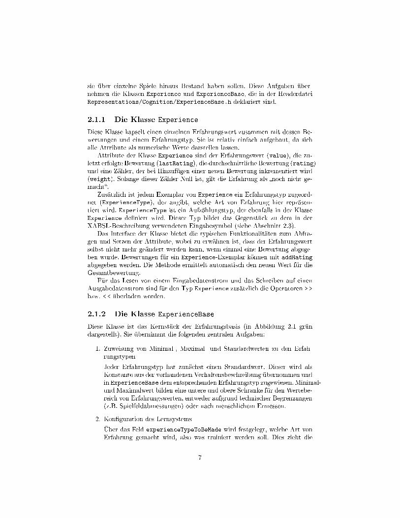
sie über einzelne Spiele hinaus Bestand haben sollen. Diese Aufgaben über-nehmen die Klassen Experience und ExperienceBase, die in der HeaderdateiRepresentations/Cognition/ExperienceBase.h deklariert sind.
2.1.1 Die Klasse ExperienceDiese Klasse kapselt einen einzelnen Erfahrungswert zusammen mit dessen Be-wertungen und einem Erfahrungstyp. Sie ist relativ einfach aufgebaut, da sichalle Attribute als numerische Werte darstellen lassen.
Attribute der Klasse Experience sind der Erfahrungswert (value), die zu-letzt erfolgte Bewertung (lastRating), die durchschnittliche Bewertung (rating)und eine Zähler, der bei Hinzufügen einer neuen Bewertung inkrementiert wird(weight). Solange dieser Zähler Null ist, gilt die Erfahrung als �noch nicht ge-macht�.
Zusätzlich ist jedem Exemplar von Experience ein Erfahrungstyp zugeord-net (ExperienceType), der angibt, welche Art von Erfahrung hier repräsen-tiert wird. ExperienceType ist ein Aufzählungstyp, der ebenfalls in der KlasseExperience de�niert wird. Dieser Typ bildet das Gegenstück zu dem in derXABSL-Beschreibung verwendeten Eingabesymbol (siehe Abschnitt 2.3).
Das Interface der Klasse bietet die typischen Funktionalitäten zum Abfra-gen und Setzen der Attribute, wobei zu erwähnen ist, dass der Erfahrungswertselbst nicht mehr geändert werden kann, wenn einmal eine Bewertung abgege-ben wurde. Bewertungen für ein Experience-Exemplar können mit addRatingabgegeben werden. Die Methode ermittelt automatisch den neuen Wert für dieGesamtbewertung.
Für das Lesen von einem Eingabedatenstrom und das Schreiben auf einenAusgabedatenstrom sind für den Typ Experience zusätzlich die Operatoren > >bzw. < < überladen worden.
2.1.2 Die Klasse ExperienceBaseDiese Klasse ist das Kernstück der Erfahrungsbasis (in Abbildung 2.1 gründargestellt). Sie übernimmt die folgenden zentralen Aufgaben:
1. Zuweisung von Minimal-, Maximal- und Standardwerten zu den Erfah-rungstypenJeder Erfahrungstyp hat zunächst einen Standardwert. Dieser wird alsKonstante aus der vorhandenen Verhaltensbeschreibung übernommen undin ExperienceBase dem entsprechenden Erfahrungstyp zugewiesen. Minimal-und Maximalwert bilden eine untere und obere Schranke für den Wertebe-reich von Erfahrungswerten, entweder aufgrund technischer Begrenzungen(z.B. Spielfeldabmessungen) oder nach menschlichem Ermessen.
2. Kon�guration des LernsystemsÜber das Feld experienceTypeToBeMade wird festgelegt, welche Art vonErfahrung gemacht wird, also was trainiert werden soll. Dies zieht die
7

Einschränkung mit sich, dass nicht mehrere Erfahrungen gleichzeitig ge-macht werden können. Hierdurch wird ausgeschlossen, dass sich die durcheine Erfahrung bewirkte Verhaltensänderung nicht auf die Bewertung ei-ner anderen Erfahrung auswirken kann. Trotzdem wäre es in der Zukunfteventuell wünschenswert, voneinander unabhängige Erfahrungen gleich-zeitig machen zu können. Diese müssten dann allerdings auch unabhängigvoneinander bewertet werden.Das Feld useExperienceMode gibt an, welche Erfahrungswerte im Spielangewendet werden sollen. Hier gibt es zwei Möglichkeiten: Die bestenvorhandenen Erfahrungswerte (useBestExperience) oder die Standard-werte (useDefaultValue). Durch Letzteres kann also die Anwendung vonGelerntem deaktiviert werden.
3. Speicherung/Wiederherstellung und Verwaltung von ErfahrungenExperienceBase bietet Funktionalität zum Hinzufügen, Entfernen undzum Zurückliefern von Erfahrungen, sowie einige Methoden zum beque-men Heraus�ltern von Erfahrungen oder Erfahrungswerten für gegebeneErfahrungstypen.Darüber hinaus gibt es Funktionen, die das Laden aller lernrelevantenInformationen aus einer Datei oder das Schreiben dieser Informationen ineine Datei erledigen.
Zur Laufzeit existiert genau ein Exemplar dieser Klasse, das von dem Pro-zess Cognition referenziert und an das Lernmodul und die Learning Symbolsübergeben wird (siehe 2.2, 2.3).
2.2 Das Lernmodul2.2.1 AufgabenDas Lernmodul be�ndet sich in Modules/Learning unterhalb des Quellcode-verzeichnisses. Neben den Interfacede�nitionen be�ndet sich dort auch eineStandardlösung, genannt DefaultLearningSolution. Das Learning-Modul be-kommt an seinen Konstruktor alle im Cognition-Prozess referenzierten Ob-jekte übergeben, also alle Informationen, die auch dem BehaviorControl zurVerfüngung stehen (siehe Abbildung 2.1). Die vom LearningSelector erzeug-te Lösung des Learning-Moduls wird im Cognition-Prozess direkt vor derBehaviorControl-Lösung ausgeführt.
Dem Lernmodul fällt die schwierigste Aufgabe innerhalb des Lernsystems zu:Es muss den Erfolg (oder Misserfolg) von Erfahrungen bewerten. Die Bewertungsollte möglichst unabhängig sein von:
• Erfolg/Misserfolg der anderen Mitspieler
• Gegnerischem Können
8
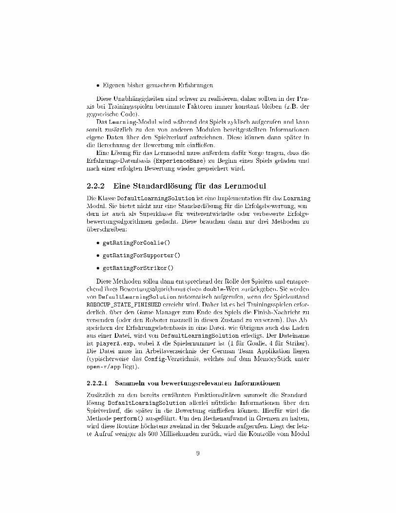
• Eigenen bisher gemachten Erfahrungen
Diese Unabhängigkeiten sind schwer zu realisieren, daher sollten in der Pra-xis bei Trainingsspielen bestimmte Faktoren immer konstant bleiben (z.B. dergegnerische Code).
Das Learning-Modul wird während des Spiels zyklisch aufgerufen und kannsomit zusätzlich zu den von anderen Modulen bereitgestellten Informationeneigene Daten über den Spielverlauf aufzeichnen. Diese können dann später indie Berechnung der Bewertung mit ein�ieÿen.
Eine Lösung für das Lernmodul muss auÿerdem dafür Sorge tragen, dass dieErfahrungs-Datenbasis (ExperienceBase) zu Beginn eines Spiels geladen undnach einer erfolgten Bewertung wieder gespeichert wird.
2.2.2 Eine Standardlösung für das LernmodulDie Klasse DefaultLearningSolution ist eine Implementation für das Learning-Modul. Sie bietet nicht nur eine Standardlösung für die Erfolgsbewertung, son-dern ist auch als Superklasse für weiterentwickelte oder verbesserte Erfolgs-bewertungsalgorithmen gedacht. Diese brauchen dann nur drei Methoden zuüberschreiben:
• getRatingForGoalie()
• getRatingForSupporter()
• getRatingForStriker()
Diese Methoden sollen dann entsprechend der Rolle des Spielers und entspre-chend ihres Bewertungsalgorithmus einen double-Wert zurückgeben. Sie werdenvon DefaultLearningSolution automatisch aufgerufen, wenn der SpielzustandROBOCUP_STATE_FINISHED erreicht wird. Daher ist es bei Trainingsspielen erfor-derlich, über den Game Manager zum Ende des Spiels die Finish-Nachricht zuversenden (oder den Roboter manuell in diesen Zustand zu versetzen). Das Ab-speichern der Erfahrungsdatenbasis in eine Datei, wie übrigens auch das Ladenaus einer Datei, wird von DefaultLearningSolution erledigt. Der Dateinameist playerX.exp, wobei X die Spielernummer ist (1 für Goalie, 4 für Striker).Die Datei muss im Arbeitsverzeichnis der German Team Applikation liegen(typischerweise das Config-Verzeichnis, welches auf dem MemoryStick unteropen-r/app liegt).
2.2.2.1 Sammeln von bewertungsrelevanten InformationenZusätzlich zu den bereits erwähnten Funktionalitäten sammelt die Standard-lösung DefaultLearningSolution allerlei nützliche Informationen über denSpielverlauf, die später in die Bewertung ein�ieÿen können. Hierfür wird dieMethode perform() ausgeführt. Um den Rechenaufwand in Grenzen zu halten,wird diese Routine höchstens zweimal in der Sekunde aufgerufen. Liegt der letz-te Aufruf weniger als 500 Millisekunden zurück, wird die Kontrolle vom Modul
9
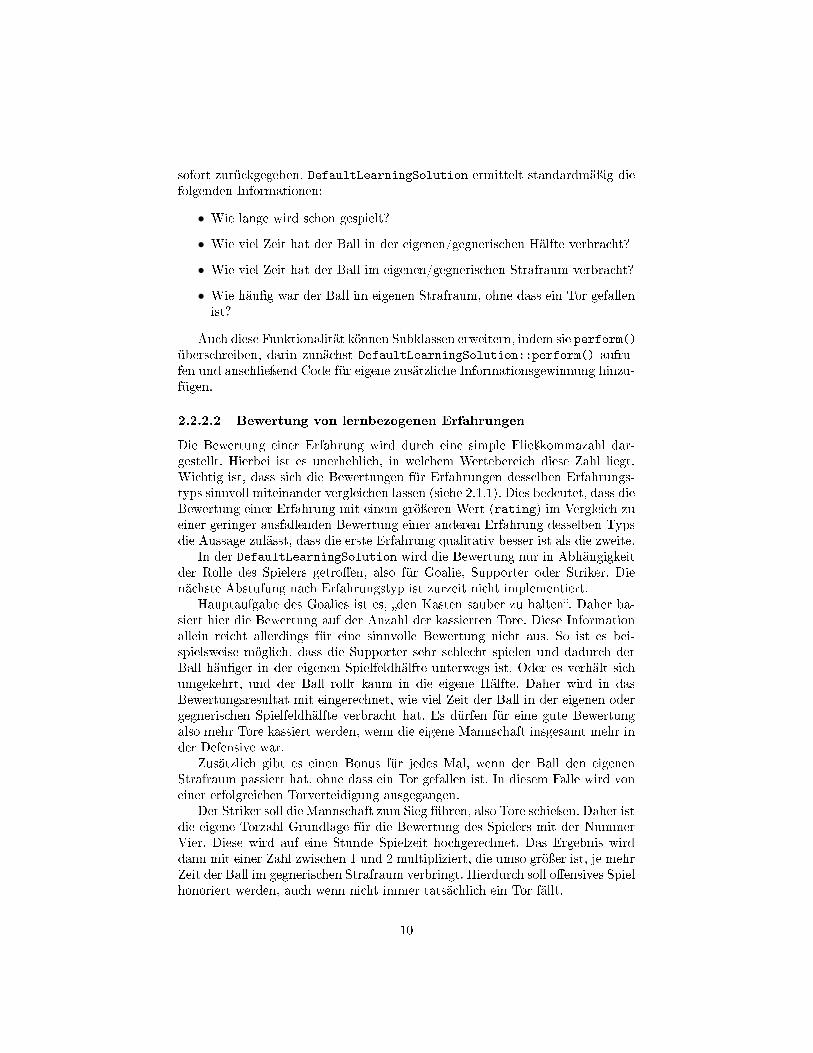
sofort zurückgegeben. DefaultLearningSolution ermittelt standardmäÿig diefolgenden Informationen:
• Wie lange wird schon gespielt?
• Wie viel Zeit hat der Ball in der eigenen/gegnerischen Hälfte verbracht?
• Wie viel Zeit hat der Ball im eigenen/gegnerischen Strafraum verbracht?
• Wie häu�g war der Ball im eigenen Strafraum, ohne dass ein Tor gefallenist?
Auch diese Funktionalität können Subklassen erweitern, indem sie perform()überschreiben, darin zunächst DefaultLearningSolution::perform() aufru-fen und anschlieÿend Code für eigene zusätzliche Informationsgewinnung hinzu-fügen.
2.2.2.2 Bewertung von lernbezogenen ErfahrungenDie Bewertung einer Erfahrung wird durch eine simple Flieÿkommazahl dar-gestellt. Hierbei ist es unerheblich, in welchem Wertebereich diese Zahl liegt.Wichtig ist, dass sich die Bewertungen für Erfahrungen desselben Erfahrungs-typs sinnvoll miteinander vergleichen lassen (siehe 2.1.1). Dies bedeutet, dass dieBewertung einer Erfahrung mit einem gröÿeren Wert (rating) im Vergleich zueiner geringer ausfallenden Bewertung einer anderen Erfahrung desselben Typsdie Aussage zulässt, dass die erste Erfahrung qualitativ besser ist als die zweite.
In der DefaultLearningSolution wird die Bewertung nur in Abhängigkeitder Rolle des Spielers getro�en, also für Goalie, Supporter oder Striker. Dienächste Abstufung nach Erfahrungstyp ist zurzeit nicht implementiert.
Hauptaufgabe des Goalies ist es, �den Kasten sauber zu halten�. Daher ba-siert hier die Bewertung auf der Anzahl der kassierten Tore. Diese Informationallein reicht allerdings für eine sinnvolle Bewertung nicht aus. So ist es bei-spielsweise möglich, dass die Supporter sehr schlecht spielen und dadurch derBall häu�ger in der eigenen Spielfeldhälfte unterwegs ist. Oder es verhält sichumgekehrt, und der Ball rollt kaum in die eigene Hälfte. Daher wird in dasBewertungsresultat mit eingerechnet, wie viel Zeit der Ball in der eigenen odergegnerischen Spielfeldhälfte verbracht hat. Es dürfen für eine gute Bewertungalso mehr Tore kassiert werden, wenn die eigene Mannschaft insgesamt mehr inder Defensive war.
Zusätzlich gibt es einen Bonus für jedes Mal, wenn der Ball den eigenenStrafraum passiert hat, ohne dass ein Tor gefallen ist. In diesem Falle wird voneiner erfolgreichen Torverteidigung ausgegangen.
Der Striker soll die Mannschaft zum Sieg führen, also Tore schieÿen. Daher istdie eigene Torzahl Grundlage für die Bewertung des Spielers mit der NummerVier. Diese wird auf eine Stunde Spielzeit hochgerechnet. Das Ergebnis wirddann mit einer Zahl zwischen 1 und 2 multipliziert, die umso gröÿer ist, je mehrZeit der Ball im gegnerischen Strafraum verbringt. Hierdurch soll o�ensives Spielhonoriert werden, auch wenn nicht immer tatsächlich ein Tor fällt.
10
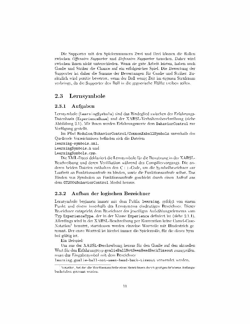
Die Supporter mit den Spielernummern Zwei und Drei können die Rollenzwischen O�ensive Supporter und Defensive Supporter tauschen. Daher wirdzwischen ihnen nicht unterschieden. Wenn sie gute Arbeit leisten, haben auchGoalie und Striker die Chance auf ein erfolgreiches Spiel. Die Bewertung derSupporter ist daher die Summe der Bewertungen für Goalie und Striker. Zu-sätzlich wird positiv bewertet, wenn der Ball wenig Zeit im eigenen Strafraumverbringt, da die Supporter den Ball in die gegnerische Hälfte treiben sollen.
2.3 Lernsymbole2.3.1 AufgabenLernsymbole (LearningSymbols) sind das Bindeglied zwischen der Erfahrungs-Datenbasis (ExperienceBase) und der XABSL-Verhaltensbeschreibung (sieheAbbildung 2.1). Mit ihnen werden Erfahrungswerte dem BehaviorControl zurVerfügung gestellt.
Im Pfad Modules/BehaviorControl/CommonXabsl2Symbols unterhalb desQuellcode-Verzeichnisses be�nden sich die Dateienlearning-symbols.xml,LearningSymbols.h undLearningSymbols.cpp.
Die XML-Datei deklariert die Lernsymbole für die Benutzung in der XABSL-Beschreibung und deren Veri�kation während des Compiliervorgangs. Die an-deren beiden Dateien enthalten den C++-Code, um die Symbolbezeichner zurLaufzeit an Funktionsaufrufe zu binden, sowie die Funktionsaufrufe selbst. DasBinden von Symbolen an Funktionsaufrufe geschieht durch einen Aufruf ausdem GT2004BehaviorControl-Modul heraus.
2.3.2 Aufbau der logischen BezeichnerLernsymbole beginnen immer mit dem Prä�x learning, gefolgt von einemPunkt und einem innerhalb des Lernsystems eindeutigen Bezeichner. DieserBezeichner entspricht dem Bezeichner des jeweiligen Aufzählungselements vomTyp ExperienceType, der in der Klasse Experience de�niert ist (siehe 2.1.1).Allerdings wird in der XABSL-Beschreibung per Konvention keine Camel-Case-Notation1 benutzt, stattdessen werden einzelne Wortteile mit Bindestrich ge-trennt. Der erste Wortteil ist hierbei immer die Spielerrolle, für die dieses Sym-bol gültig ist.
Ein Beispiel:Um aus der XABSL-Beschreibung heraus für den Goalie auf den aktuellen
Wert für den Erfahrungstyp goalieBallNotSeenHeadBackTimeout zuzugreifen,muss das Eingabesymbol mit dem Bezeichnerlearning.goalie-ball-not-seen-head-back-timeout verwendet werden.
1Notation, bei der die Wortbestandteile eines Bezeichners durch groÿgeschriebene Anfangs-buchstaben getrennt werden.
11
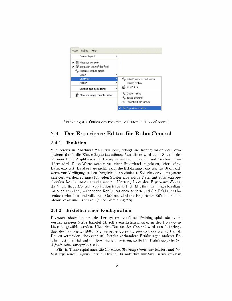
Abbildung 2.3: Ö�nen des Experience Editors in RobotControl.
2.4 Der Experience Editor für RobotControl2.4.1 FunktionWie bereits in Abschnitt 2.4.1 erläutert, erfolgt die Kon�guration des Lern-systems durch die Klasse ExperienceBase. Von dieser wird beim Starten derGerman Team Applikation ein Exemplar erzeugt, das dann mit Werten initia-lisiert wird. Diese Werte werden aus einer Binärdatei eingelesen, sofern dieseDatei existiert. Existiert sie nicht, kann die Erfahrungsbasis nur die Standard-werte zur Verfügung stellen (vergleiche Abschnitt ). Soll also das Lernsystemaktiviert werden, so muss für jeden Spieler eine solche Datei mit einer entspre-chenden Kon�guration erstellt werden. Hierfür gibt es den Experience Editor,der in die RobotControl Applikation integriert ist. Mit ihm kann man Kon�gu-rationen erstellen, vorhandene Kon�gurationen ändern und die Erfahrungsda-tenbasis einsehen und editieren. Geö�net wird der Experience Editor über dieMenüs View und Behavior (siehe Abbildung 2.3).
2.4.2 Erstellen einer Kon�gurationDa nach Inbetriebnahme des Lernsystems zunächst Trainingsspiele absolviertwerden müssen (siehe Kapitel 4), sollte ein Erfahrungstyp in der Dropdown-Liste ausgewählt werden. Über den Button Set Current wird nun festgelegt,dass der hier ausgewählte Erfahrungstyp derjenige sein soll, der trainiert wird.Um zu vermeiden, dass eventuell bereits vorhandene Erfahrungen anderer Er-fahrungstypen sich auf die Bewertung auswirken, sollte für Trainingsspiele Usedefault value ausgewählt sein.
Für ein Turnierspiel muss die Checkbox Training Game unselektiert und Usebest experience ausgewählt sein. Dies macht natürlich nur Sinn, wenn zuvor in
12
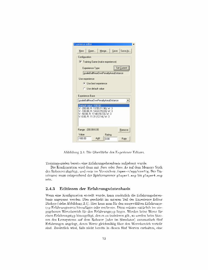
Abbildung 2.4: Die Ober�äche des Experience Editors.
Trainingsspielen bereits eine Erfahrungsdatenbasis aufgebaut wurde.Die Kon�guration wird dann mit Save oder Save As auf dem Memory Stick
des Roboters abgelegt, und zwar im Verzeichnis /open-r/app/config. Der Da-teiname muss entsprechend der Spielernummer player1.exp bis player4.expsein.
2.4.3 Editieren der ErfahrungsdatenbasisWenn eine Kon�guration erstellt wurde, kann zusätzlich die Erfahrungsdaten-basis angepasst werden. Dies geschieht im unteren Teil des Experience EditorDialogs (siehe Abbildung 2.4). Hier kann man für den ausgewählten Erfahrungs-typ Erfahrungswerte hinzufügen oder entfernen. Diese müssen natürlich im vor-gegebenen Wertebereich für den Erfahrungstyp liegen. Werden keine Werte füreinen Erfahrungstyp hinzugefügt, den es zu trainieren gilt, so werden beim Star-ten des Lernsystems auf dem Roboter (oder im Simulator) automatisch fünfErfahrungen angelegt, deren Werte gleichmäÿig über den Wertebereich verteiltsind. Zusätzlich wird, falls nicht bereits in diesen fünf Werten enthalten, eine
13
Erfahrung mit dem Standardwert erstellt. Für das Testen und Bewerten vonErfahrungswerten wird der Wert mit der kleinsten Anzahl von Bewertungen -also mit dem kleinsten Wert für weight - gewählt, und zwar in der Reihenfolgewie im Experience Editor dargestellt.
Zusätzlich gibt es die Möglichkeit, manuell Bewertungen abzugeben. Diessoll allerdings nur zu Testzwecken geschehen und ist mit einer Sicherheitsabfragebelegt.
Die Funktion Merge erlaubt es dem Benutzer, zu der aktuell geö�neten Er-fahrungsdatenbasis eine andere Erfahrungsdatenbasis hinzuzufügen. So könnenunabhängig voneinander gewonnene Erfahrungen zu einer Datenbasis zusam-mengelegt werden. Hierbei werden ganz neue Erfahrungen neu angelegt, wäh-rend bereits vorhandenen Erfahrungen die Bewertungen aus der mit der Merge-Funktion ausgewählten Erfahrungsdatenbasis hinzugefügt werden. Hierbei istdarauf zu achten, dass dieselben Erfahrungsbasen nicht mehrmals zusammenge-führt werden, da sonst die Bewertungen identischer Erfahrungen das doppelteGewicht bekommen.
14
Kapitel 3
Vorgehensweise zumHinzufügen eines neuenErfahrungstyps
Wenn in der Verhaltensbeschreibung konstante Werte durch veränderliche Er-fahrungswerte ersetzt werden sollen, so müssen für gleichartige Klassen solcherKonstanten neue Erfahrungstypen hinzugefügt werden. Dies ist auch der Fall,wenn die Verhaltensbeschreibung unter Verwendung des Lernsystems erweitertwerden soll. Im Folgenden wird chronologisch erläutert, an welchen Stellen desCodes hierfür welche Änderungen notwendig sind.
3.1 Registrieren des ErfahrungstypsZunächst muss der neue Erfahrungstyp beim Lernsystem registriert werden.Hierfür genügen einige Anpassungen in der Klasse Experience, HeaderdateiExperienceBase.h.
Die De�nition für den Aufzählungstyp ExperienceType (siehe Klassendia-gramm in Abbildung 2.2) muss um den neuen Typ erweitert werden. Hierbei istes wichtig, dass der neue Typ in der Aufzählungsreihenfolge nach den bereitsvorhandenen eingefügt wird, da es sonst beim Einlesen älterer Erfahrungsda-tenbanken aus einer Datei zu Fehlern kommen kann. Das letzte Element derAufzählung muss numberOfExperienceTypes sein.
Damit der Erfahrungstyp im Experience Editor dargestellt werden kann,sollte zusätzlich die statische Methode getExperienceTypeName erweitert wer-den, so dass für den neuen Typ der entsprechende lesbare Name zurückgegebenwird.
15
3.2 Festlegen des Wertebereiches und des Stan-dardwertes
Minimal-, Maximal- und Standardwert für die Erfahrungstypen werden in derKlasse ExperienceBase verwaltet. Im Konstruktor dieser Klasse be�nden sichdie Zuweisungen hierfür. Die Arrays defValue, minValue und maxValue (defaultvalue, minimum value und maximum value) müssen hier für den neu hinzuge-fügten Erfahrungstyp mit Werten belegt werden, wobei gilt:
minValue[n] ≤ defValue[n] ≤ maxValue[n] undminValue[n] 6= maxValue[n] für einen Erfahrungstyp n
3.3 Registrieren des XABSL-EingabesymbolsWie in Abschnitt 2.3 beschrieben, muss der neue Erfahrungstyp nun der XABSL-Engine unter einem logischen Bezeichner bekannt gemacht werden. Wie dieserBezeichner aufgebaut sein soll, ist ebenfalls in Abschnitt 2.3 erläutert. In derMethoderegisterSymbols(Xabsl2Engine& engine),die sich in der Klasse LearningSymbols be�ndet, �nden die Aufrufe zum Re-gistrieren der Lernsymbole statt. Es gibt generell zwei Möglichkeiten, um einEingabesymbol einem Wert zuzuordnen:
• Über einen ZeigerDieser enthält die Speicheradresse, in der sich der aktuelle Wert vom Typdouble für das Eingabesymbol be�ndet.
• Über einen FunktionszeigerDieser enthält die Einsprungadresse einer Funktion mit einem Rückga-bewert vom Typ double, die den aktuellen Wert für das Eingabesymbolzurückliefert.
Für die bisher registrierten Eingabesymbole wurde die zweite Alternative ge-wählt, indem zu der Klasse LeaningSymbols Funktionen hinzugefügt wurden,die jeweils den Erfahrungswert aus dem ExperienceBase-Objekt liefern. Dieshat den Vorteil, dass die Auswertung eines Eingabesymbols über Debugging-Code zurückverfolgt werden kann. Hinzu kommt die Möglichkeit, zusätzlicheInformationen zu gewinnen, etwa über die Häu�gkeit der Auswertung bestimm-ter Symbole in bestimmten Spielsituationen, oder über die gesamte Länge einesSpiels. Daher wird empfohlen, bei Hinzufügen eines Erfahrungstyps dessen Ein-gabesymbol mit einer Funktion zu verknüpfen.
3.4 Anpassung der VerhaltensbeschreibungFür die im Rahmen dieser Projektarbeit erstellten Erfahrungstypen wurde dieXABSL-Verhaltensbeschreibung bereits für die Benutzung der entsprechenden
16
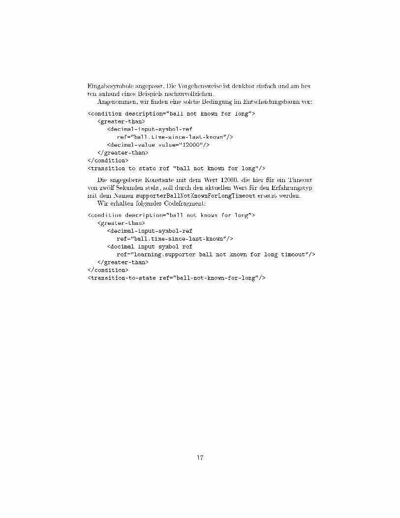
Eingabesymbole angepasst. Die Vorgehensweise ist denkbar einfach und am bes-ten anhand eines Beispiels nachzuvollziehen.
Angenommen, wir �nden eine solche Bedingung im Entscheidungsbaum vor:<condition description="ball not known for long">
<greater-than><decimal-input-symbol-ref
ref="ball.time-since-last-known"/><decimal-value value="12000"/>
</greater-than></condition><transition-to-state ref="ball-not-known-for-long"/>
Die angegebene Konstante mit dem Wert 12000, die hier für ein Timeoutvon zwölf Sekunden steht, soll durch den aktuellen Wert für den Erfahrungstypmit dem Namen supporterBallNotKnownForLongTimeout ersetzt werden.
Wir erhalten folgendes Codefragment:<condition description="ball not known for long">
<greater-than><decimal-input-symbol-ref
ref="ball.time-since-last-known"/><decimal-input-symbol-ref
ref="learning.supporter-ball-not-known-for-long-timeout"/></greater-than>
</condition><transition-to-state ref="ball-not-known-for-long"/>
17
Kapitel 4
Durchführung desLernprozesses
Nachdem nun die Komponenten des Lernsystems und deren Funktionsweisenund Implementierungen vorgestellt und die Vorgehensweise für die Entwicklungund Einbindung neuer Erfahrungstypen erklärt wurden, stellt sich nun die Frage:
Wie wird das Lernsystem praktisch eingesetzt, also wie lernt der Roboter?Die Antwort: Der Roboter lernt durch Training. Nachdem für die Spieler
einer Mannschaft Kon�gurationen erstellt wurden (siehe 2.4.2), müssen Trai-ningsspiele absolviert werden. Hierbei ist es wichtig, diese unter möglichst gleichbleibenden, wettkampfähnlichen Bedingungen durchzuführen.
Die gegnerische Mannschaft soll hierbei nicht lernen, sondern nur die Stan-dardwerte für alle Erfahrungstypen benutzen. Für die Optimierung des Spiel-verhaltens im Hinblick auf einen speziellen Gegner können auch Trainingsspielegegen Roboter ausgetragen werden, die den Code genau dieses Gegners benut-zen, sofern dieser verfügbar ist. In diesem Falle müssen allerdings speziell fürdiesen Gegner neue Erfahrungsdatenbasen angelegt werden.
Nach Beendigung eines Trainingsspiels müssen alle Roboter in den Zustandfinished versetzt werden, damit die Bewertung des Spiels erfolgt. Anschlieÿendkann sofort ein neues Trainingsspiel beginnen. Der Roboter wird nun für den zutrainierenden Erfahrungstyp den nächsten Erfahrungswert auswählen. Es solltenfür jeden Erfahrungstyp möglichst viele Trainingsspiele durchgeführt werden,damit eine repräsentative Gesamtbewertung entstehen kann.
18

Kapitel 5
Fazit und Bewertung
Das Anlegen einer umfangreichen Erfahrungsdatenbasis mit Hilfe von Trainings-spielen ist ein sehr aufwändiger Vorgang, da alle Erfahrungswerte für alle Er-fahrungstypen möglichst oft bewertet werden müssen. Nur so kann das Gesamt-verhalten des Roboters im Spiel mit Hilfe des Lernsystems sinnvoll optimiertwerden. In der Praxis hat sich herausgestellt, dass das Austragen von Trainings-spielen in �physikalischer Form�, also mit Robotern auf dem Feld sehr viel Zeitkostet. Besondere Schwierigkeiten bereiteten hierbei variable Lichtverhältnisse.
Leider war es aus diesem Grund bisher noch nicht möglich, einen tatsächli-chen Zuwachs der Siegerquote festzustellen. Die Evaluation dessen, ob und wieweit durch den Einsatz des Lernsystems ein taktischer Vorteil entsteht, wirddaher noch mehr Zeit benötigen.
Tests mit dem Goalie im Simulator waren hingegen erfolgreicher. Bewertun-gen �elen nach erkennbar schlechter Leistung des Torwarts geringer aus als nachSpielen mit erfolgreicher Verteidigung des eigenen Tores. Setzt man nun voraus,dass die Leistung eines Spielers in einer ansonsten gleichbleibenden Testumge-bung ausschlieÿlich von den sich ändernden Erfahrungswerten abhängt, so lässtdies die Schlussfolgerung zu, dass das Prinzip der Bewertung von Erfahrungenauch in der Praxis eine Optimierung des Spielverhaltens nach sich zieht.
Diese Projektarbeit ist als die Umsetzung des Konzepts eines Lernsystems,das auf Erfahrungswerten und deren Bewertung basiert, einzustufen. Hierbeiwurde besonderer Wert auf Erweiterbarkeit gelegt, das Projekt kann und sollalso auch als Infrastruktur für künftige erweiterte und verbesserte Implementie-rungen dienen.
Um einen den praktischen Aufwand beim Einsatz des Lernsystems in Gren-zen zu halten, scheint es allerdings unvermeidbar, den RobotControl-Simulatorso zu erweitern, dass Trainingsspiele auch ausschlieÿlich als Simulationen statt-�nden können. Hierbei könnte man auf verschiedenen Rechnern parallel Trai-ningsspiele simulieren, so dass sich relativ schnell gute Lernergebnisse realisierenlieÿen.
19
Literaturverzeichnis
[1] Bach, J., Burkhard, H.-D., Jüngel, M., Lötzsch, M. Designing Agent Beha-vior with the Extensible Agent Behavior Speci�cation Language XABSL.Lecture Notes in Arti�cial Intelligence, Padova, Italy. Springer 2004
[2] Dahm, I., Dü�ert, U., Ho�mann, J., Jüngel, M., Kallnik, M., Lötzsch, M.,Risler, M., Röfer, T., Stelzer, M., Ziegler, J. GermanTeam2003. Lecture No-tes in Arti�cial Intelligence, Padova, Italy. Springer 2004
[3] Röfer, T. An Architecture for a National RoboCup Team. Lecture Notes inArti�cial Intelligence. Springer 417-425 2003
[4] Shoham, Y. Agent-oriented programming. Robotics Laboratory, StanfordUniversity 1992
[5] V. Butz, M. Anticipatory behavior in adaptive learning systems. Springer2003
20


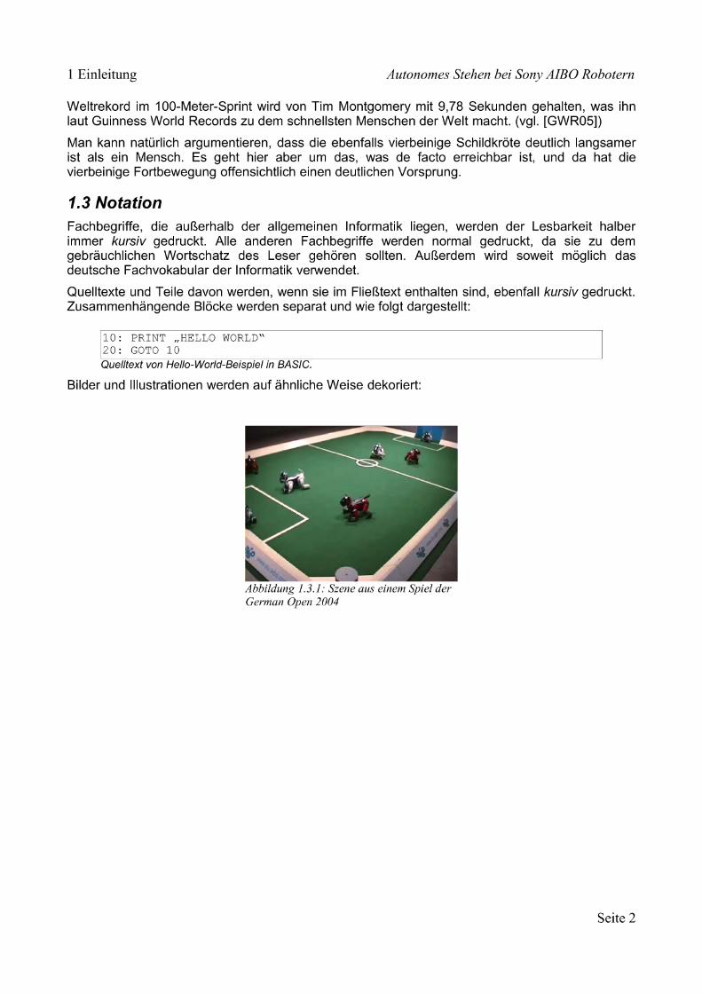
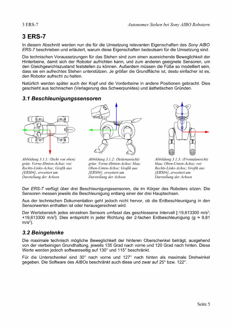
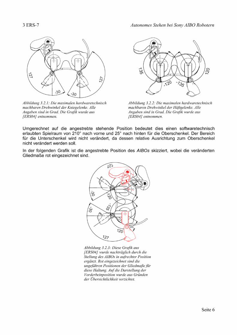
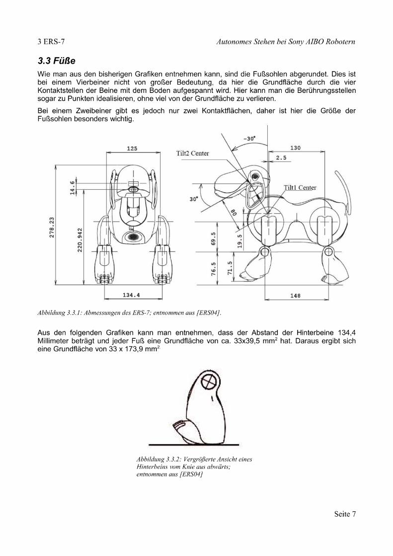
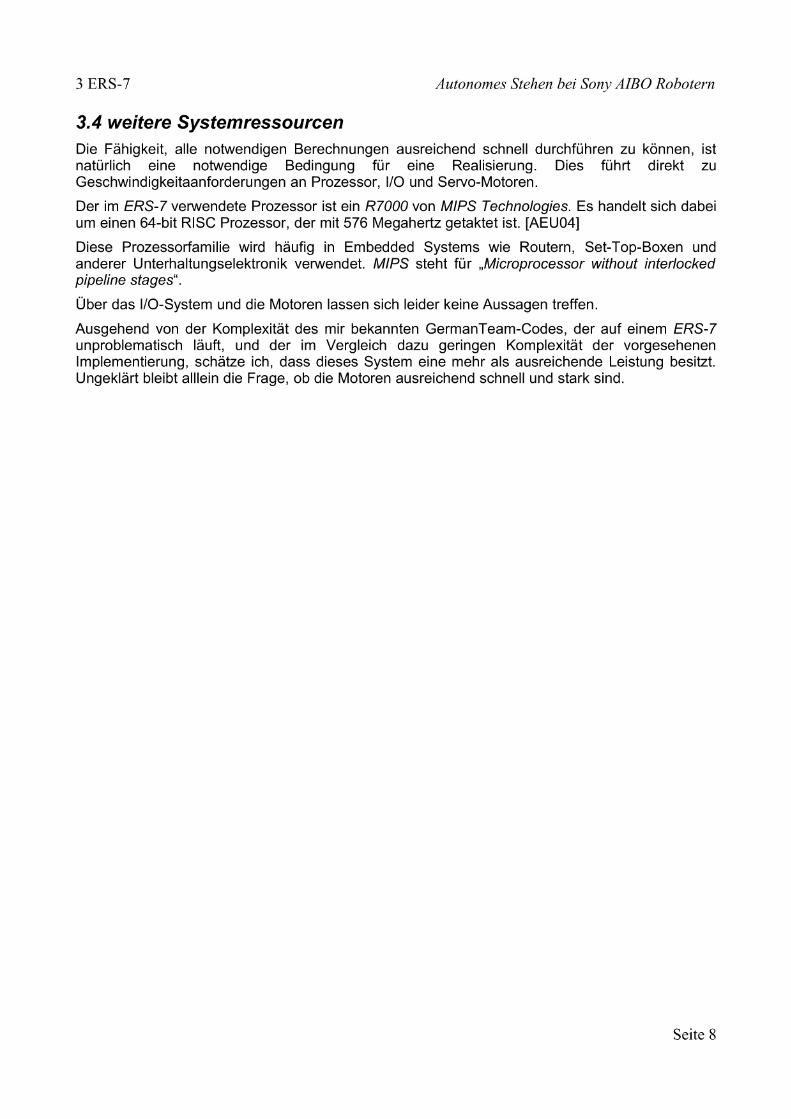
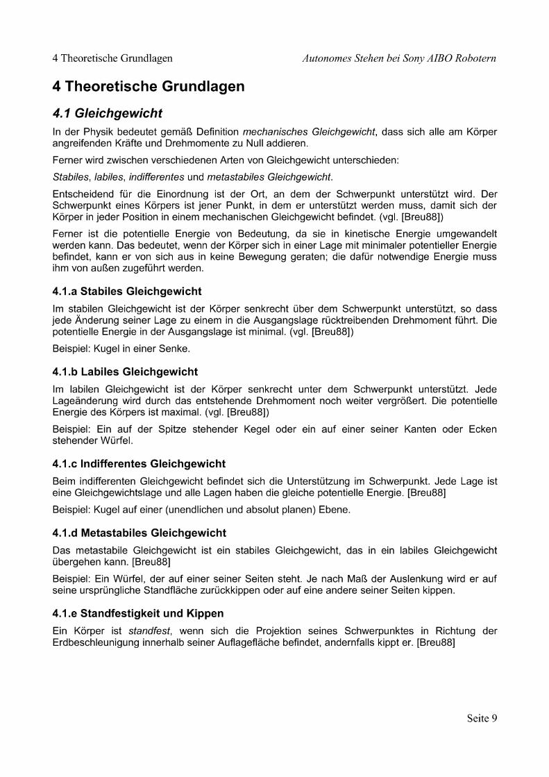
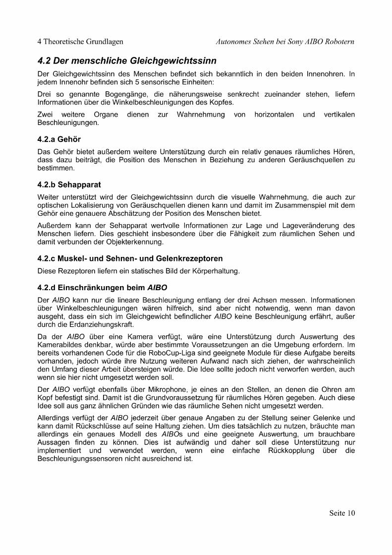
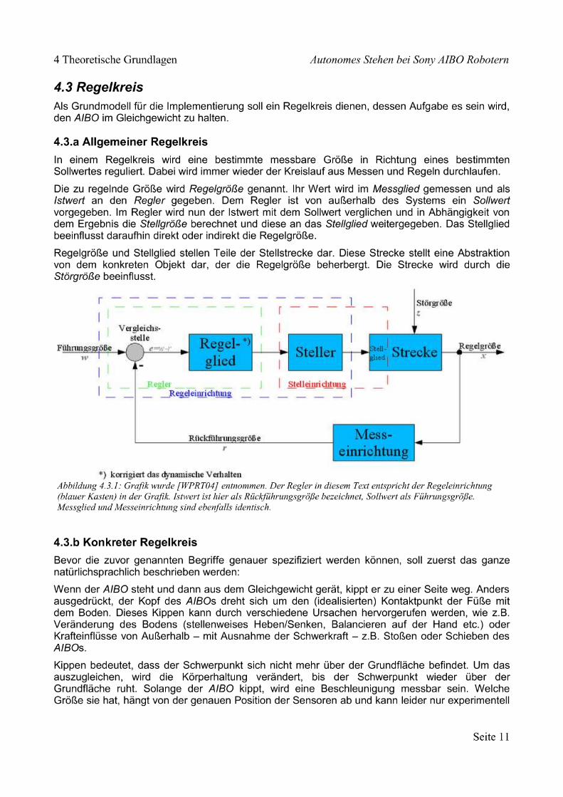
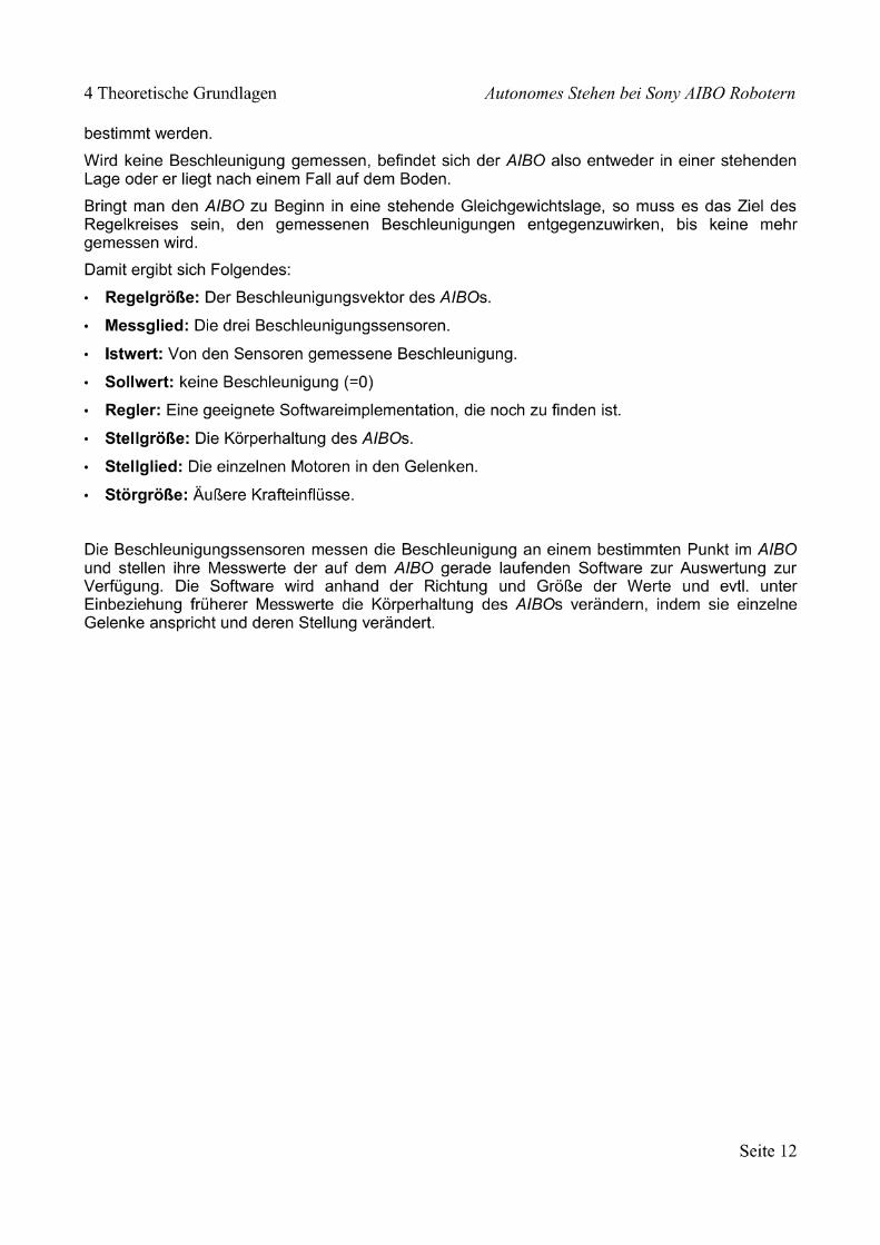
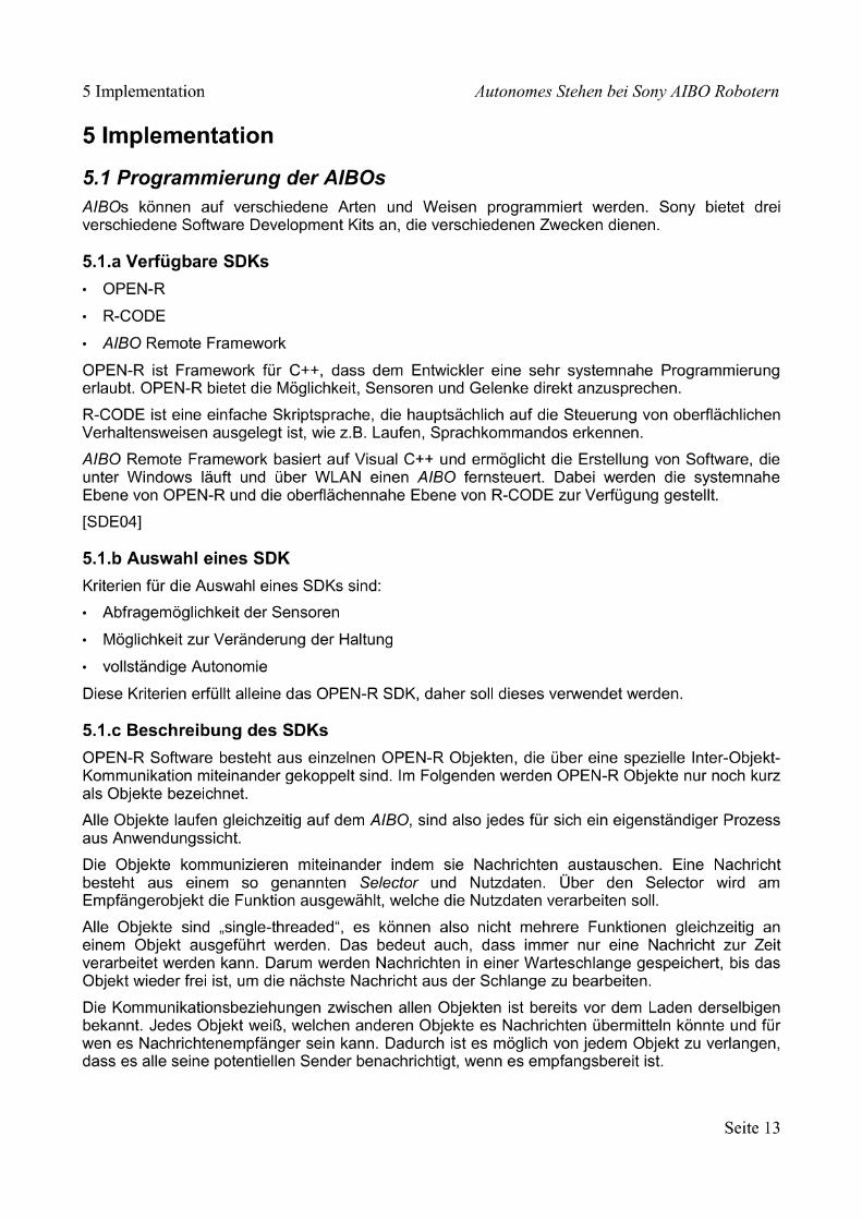
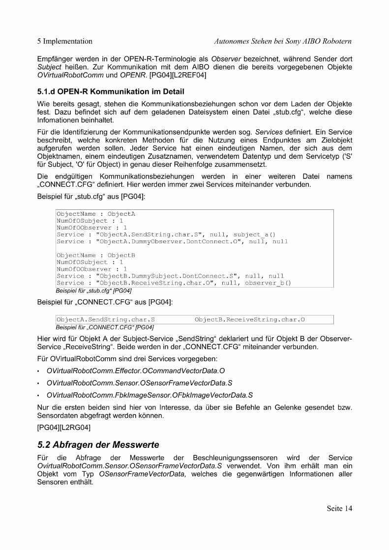
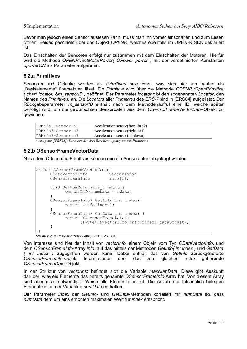
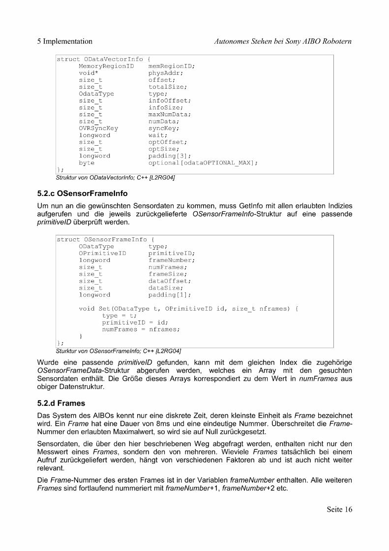
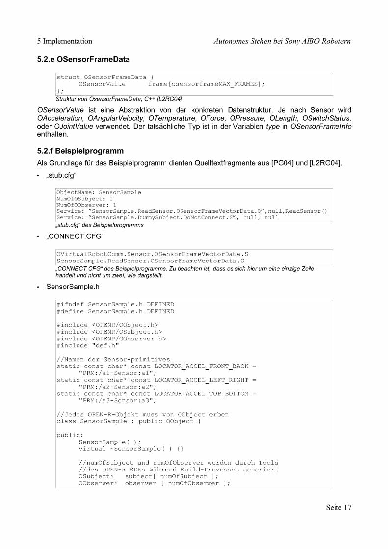
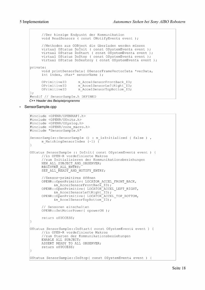
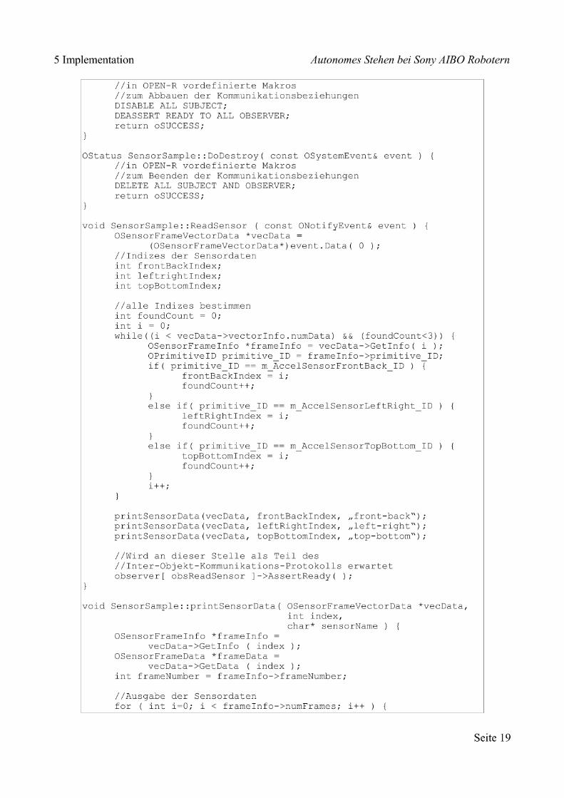
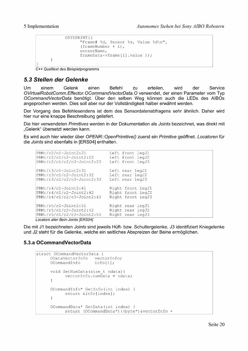

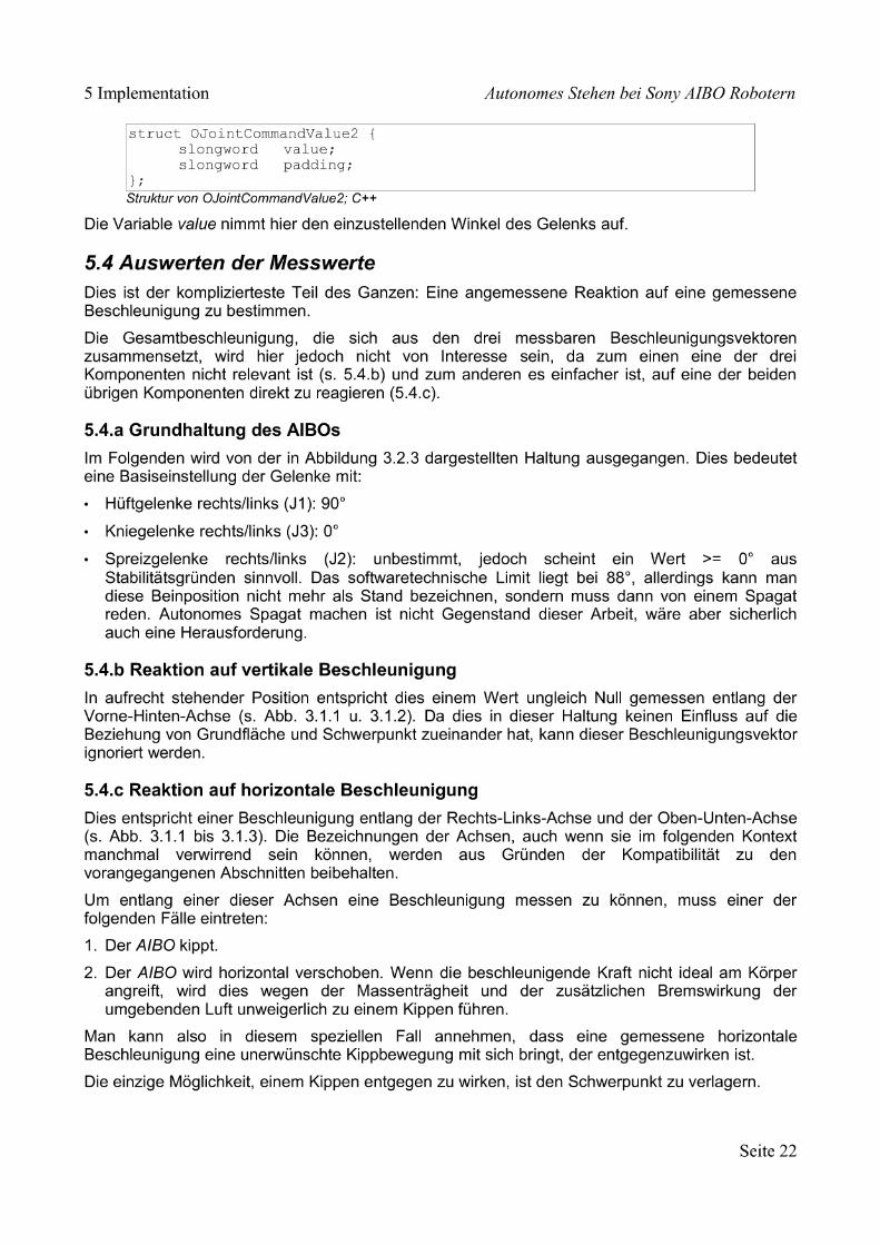
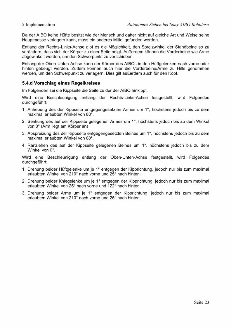

����������� ������ ����������������������� ��������������� !∀�������#�∃�����% ������&∋�����
(��)���∗+�������,+�������������−��./0 1����21���3(���45
(��)����������∗������������� ��������� �
���������������������� �
�������������
��−,1����������6���∗
∋��������7�38������������/�������4%��%5����� ��2��38������������/������%∃�∃��5
������������������
9��−��∗����� ��2��
�
� ��
�������������� ����� ������������������������������������������������������������������������������������������������������������������������� ����������� ���!�� �������������������������∀��!#��∃���������������#��%��&�����∋��(�)� �����������������������
�∀����������������������� �����������������������∃�������� �∃�����# ����������������������������������������������������������������������������������������������∗�
������+���&���,�������)�#���&���,�������� ��#�������(������+����!#� ������������������������������������������������������������������������������������������������������−�
�∗��)�#���&���,��������������������������������������������������������������������������.����∗���������������������������������������������������������������������������������������������.�
� � �:4:4:6−�9������−�:::::::::::::::::::::::::::::::::::::::::::::::::::::::::::::::::::::::::::::::::::;� � �:4:�:6−�<2����:::::::::::::::::::::::::::::::::::::::::::::::::::::::::::::::::::::::::::::::::::::::::::=�� � �:4:∃:6−�+������:::::::::::::::::::::::::::::::::::::::::::::::::::::::::::::::::::::::::::::::::::::::4�
� ���∗�∀��∃�����������������������������������������������������������������������������������/�� ���∗����������(�������0�1�������!����∃�����# ������������������������������
�:∃:4:6−�>?∃9������−�::::::::::::::::::::::::::::::::::::::::::::::::::::::::::::::::::::::::::44� � �:∃:�:(������,9���2���.����������:::::::::::::::::::::::::::::::::::::::::::::::::::4∃�
���∗�∗���� �(��� �1����!∋����%�� �0��#��!����� ������∋����������������:�:4:8��−��������::::::::::::::::::::::::::::::::::::::::::::::::::::::::::::::::::::::::::::::::::::4∃�:�:�:1���::::::::::::::::::::::::::::::::::::::::::::::::::::::::::::::::::::::::::::::::::::::::::::::::::::::4∃
������−��2�������� ������� ��������������������������������������������������������������������������∗�������.��1���������(����#������ ��� ��������������������������������������������������������∗�
;:4:(������:::::::::::::::::::::::::::::::::::::::::::::::::::::::::::::::::::::::::::::::::::::::::::::::::::::::::4�;:�:∋�>����−������������������&���������2��������������::::::::::::::4�;:∃:.�������+����1�����≅�����,�−�(����������−�.����������−�
����2:::::::::::::::::::::::::::::::::::::::::::::::::::::::::::::::::::::::::::::::::::::::::::::::::::::::::::::4�
������3����(����������������������������������������������������������������������������������������������������−
��
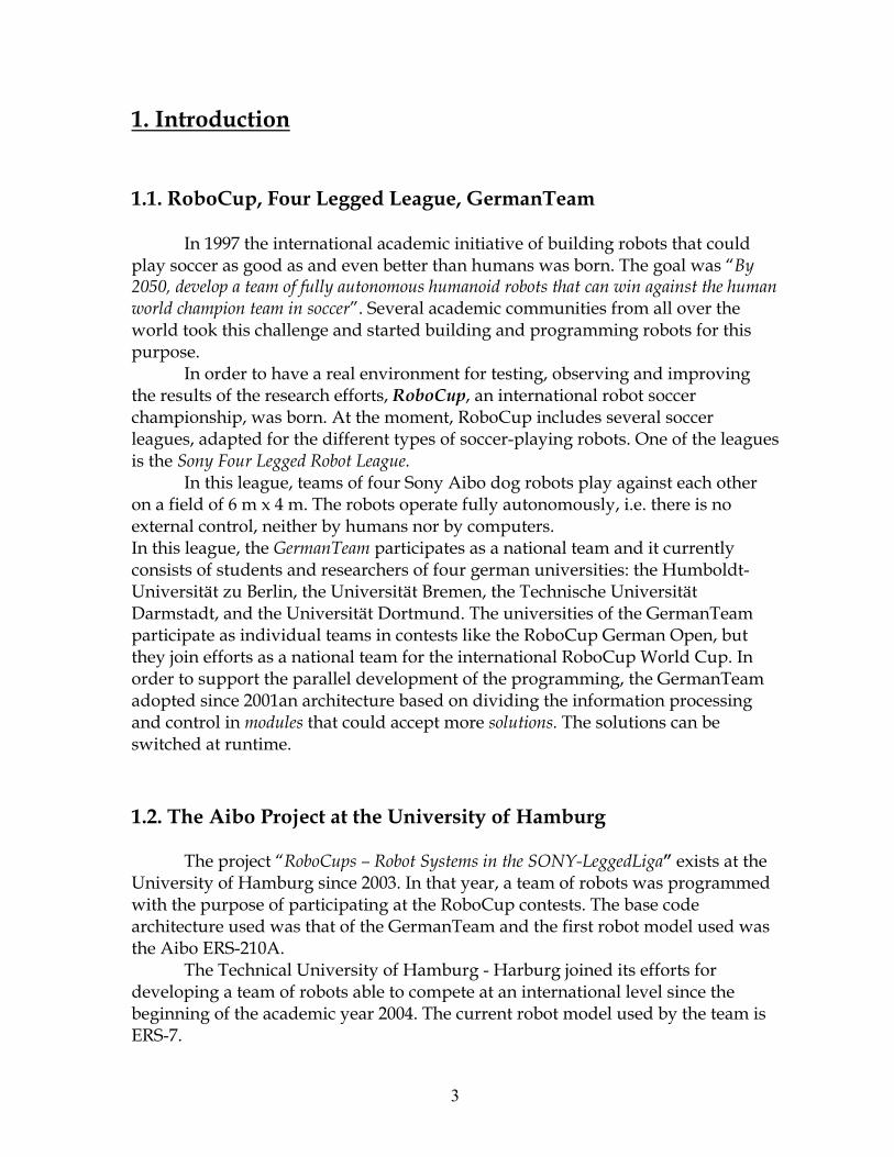
� ��
�������� ��������
���������������������� ����������� ��!�� ������������������� ����������������� ���������� � ��������� ����
������ �������� ���������������������������������� �������� �������������������� ����������������������������������������������������������������������������������� ��������������������������������� ��������� ������ ������� ����� ������������������������������������� ��������� � ���� ���������� ����
��� ����� �������������� ������ �������!� �������������� �������������� �������������� ���!�������!���������� ����� � ��� ��������� ����!������ ����∀������ ���!�# � ∃����������������� ���������!��������� ����������������� ��� ���%�������� � ����&�� ����������������������������������������� �
�����������!������ ��� ���� ���∀� �� ��� � ������������������� ���� �������� ��∋���(�)�������� � ��� �������������� � � ����!����������� �(������� ��� �!����������������� ������ �������������������!����!����∀��������������������� ������������������������ ������ ����������������������� ��� ����������������∗����+��� ���%,�����−��.��/���!����,�����−��/���!������������,�����−��0��������!��������,�����−��0 ������������������� �����1������������������������������������ ������� ����# � ∃���1�����&��!���������2 ���� ������������ ��������� ����������� ����# � ∃���3 ����∃������� ����� ����� ����������������� ����� ������� �������!����1���������� ��������455������������������� ������������� ���� ���� ����������� ��� ����������������� ����������� ����������� ����� ��� ��������������������������
����∀��!#��∃���������������#��%��&�����∋��(�)� �����
����� 2��������#� ��∃���������������������%&∋(��������Α(����������
,������� ��+�����������4556�������������!������� ��� � ��������� ������������������ �� �������������������# � ∃���� ��������������� ������������������������� �����1��������������������� � ��� ��������������∀� �7#�%4�5∀��
�����������,������� ��+�������%�+�������2 �������� ����� ����� ���������� ��� � �������� �� ���������������� ���������������������� ����������������455)������������� � ��� �������������������7#�%���
� ��
∀����������������������� �����������������������∃�������� �∃�����# �
∀������� ���������� ������ � ��� ������������������ ��� ������
� ���.�� �� ����� �� ����� � ����∀�� � �������������� ��� ����������� ���������� ����������������� �������������������� ���������������� �� �� ���������� � ��� ���������������������������������455)84559����� ��� ����������������������������� 2����������������� ���������� ���.�� �� ����� �� ����� � �������� � �� ����
���������������� ��������� ����� �%����������!��������� �������� � ����������������� ����������������!���������� ��������������!��� ������ ���� � �:��� ����� ��� ������������������������� ���� ���� � ������� �������(������������ �����������������������!������ ������ �����������∀�������������� � �:��� ��������!������ �������� ��������;5�������� ��!��� ����� ���� ������������� � ���� ����������������������� ������� �����!����������� �������;5�������,���������� ��!������������ ����� � �!�������� ��������� ����� �� ������ � ������������������������������ ����� � �������������������� �������� ������������������;5����������������������������������������� �� ������ � �������������������� ������������� ��:��� �� ��������;5�������� ���������� ����� ����������������������������� �� �� ��������������� ��������� ����� ��������������������� ������������� �� ����<�����∗������������!�� ��������=∗��
�=� ������� �������������0��� ������ >�����������������(����������!������ ������ � �!������
� � ��������� ������� � ����������� 3�����������(����� ���!�������� �%������� ������ ������������
�������������(���� �����������������������������(������� ����������������������������
��� > �����������!���������� ���(��������� �����������:��� �� ���������������!��� ������� ����������!���∗�� � �!�� �����%� (!����!����
��� >� ������ �� ��� ����������!� �������� ��� ���������������%������ �����
���=� ∀������������ ��
���� > ������� ��� ��������������������������� �������������� ��∗�
����� ��������!�� �������� !���������� !����!������!��������������������������
� ��
��� #�������� ��=����������� ����?� ������� ��� ����=��
���=� ∃�������� ����=��> ����������������������������� �!��������������� ������ �� ������������ �� ����������������� ���������������������������������� ������ �������������� ���������� � �:��� �����
�≅=� ∀����������� Α��������������� ������ ��������� � �������;5������
�� ������ 1� ������������������������������������ ����� ������ � ������
����� ��������� > ���������� � ��������������≅=�4=!�� ��������������!�
���� ������ ����� ��������� ���� �������� � ���
+ ���!������ ������������������ ������ � ������������ ������������������������� �������������� ���!������ ��� �� ����� �� ����� � �������� ���.�� �� ������ � ������������ ������� ����������
��
�
�����+���&���,�������)�#���&���,�������� ��#�������(������+����!#� �
∀���������.������� ���(��� ������� ���!������ ���� ���� ��� ��
����� ���.�� �� �� �� ����� � �������� ������� ����.������ �������∗����� �%������ ���� ����������������%������ ���� ������������ ���� ������������� ��� ������������!������� �������������(���������������� ����� �� ������������ ���� ����
��������� ����� ������������������ �������������������� �������(�������������������� �%������ ������� �������������� � � ������������ �� �������������������!�� � ������������������� ������=������ ��������������� ���������������������� ������� �������� ������������������ �������� �������
∀������!������ ������������������������������∀���������������� ���� ���� �!������������ �� ������� ������������ ��� ��������������������� �2�����
�������������� ���������� �� � ������������������������������� �� ������������������������� �� �������������������� ���������������� ������!������� ������ ����������� �%������ ���������
� ��
������������Β����������∗�� ���� � �?�88%Χ����������� � ��<��!����!����=�� ������?�88%Χ����∀���
���∗∗��� �∆�≅�� �4∆��Χ�Χ�� �� ��?�88%Χ����� �� ��� �����������<������� ��� ������� �����=�
≅�� �4∆��Χ�����?�88%Χ��������� ���������Ε���(4(4∆��Χ��� (?�88%Χ�/ �����%#������� ������������ ��� ���?�88%Χ��� �������������������������� ���� �����������
������������� �����������?�88%��������� �����������
���������∗�����Γ��
������������ ����������� �%������ ���������� ������� ����������� ������ ���� �� ����� � ���������������� ������������ � �������.����������������������� ��������� � ��� ��������!������ ������� ���� ��������� ������ �%������ ������ ����������������������������
∗��)�#���&���,���������������
∗������������������� �
����������� � �����+��%�Η���≅� ����������� ���������� ��� ���� ��������� ��������� �� ���� ���� �������� �����Η �%Η���≅� ������������������������ �� ���������������������������� ������� ����������!����������������� �������������� ���� �����
��:4:4:6−�9������−�
������ ���������� ��������������� ��� �.�� ����� ������������
7��%Α ���>����� ����������������������� �� ����1�������� ����� ���!��������� � �������� ��� �������� ������� ����
������������������������������ �������=� >�������� �� ����������� ��������������������������<������
(���������� �� �������∀�����/=�4=� ∃ ������������������ ������� ���� ���������6=� ���������������������������������������� ��!����� ��� ��
����� �����������
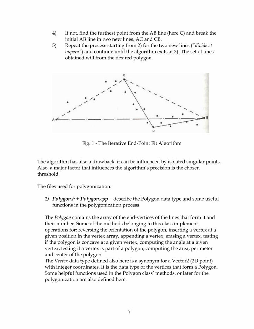
� �
)=� ���� �!����������������� ����� �����∀/����<���∃=�������� ���������∀/�������� �������!�∀∃�����∃/��
9=� #��������� �������������� ��4=�� ������� ��������<���������� ��)=������ ���������������� �����(������6=�������� ������ ������������ ����������� ��� ���
��
��� � � >�����%�����������7��%Α ���>��∀�� �����
������� ������������ ���������� ∗��������������������� �������������� �����∀�� !�����2 ������ ��������������������� ����:������ ��������� �������� ����������������� ��� ��� �.�� �∗�
���� ���������∗�������������(����������Α ��� ���������������� ��������
����� ��������� ��� �.�� ���� �����
���+�������� ��������������� �������%������ ��������������� ��������������������� �� �������� ����� ������ ������������������ ���� ���� �∗����������� ����� �� ������ ��� �!�������������(����������� �� ����������(������!��������������(!������������(!������������� ��� ����� �����������������(!�� ���������������������������(!��������������(�������� ����� ��� �!�� �������������!���������������� ������ ��� �������≅��,������������������ ����������� ����� ����≅�� �4�<40�� ��=����������� ������������������������� ����������������� �����Α ��� ���� �������������� ������������Α ��� �������:���� ��!� �������� ������ ��� �.�� �������� ��������∗�
�
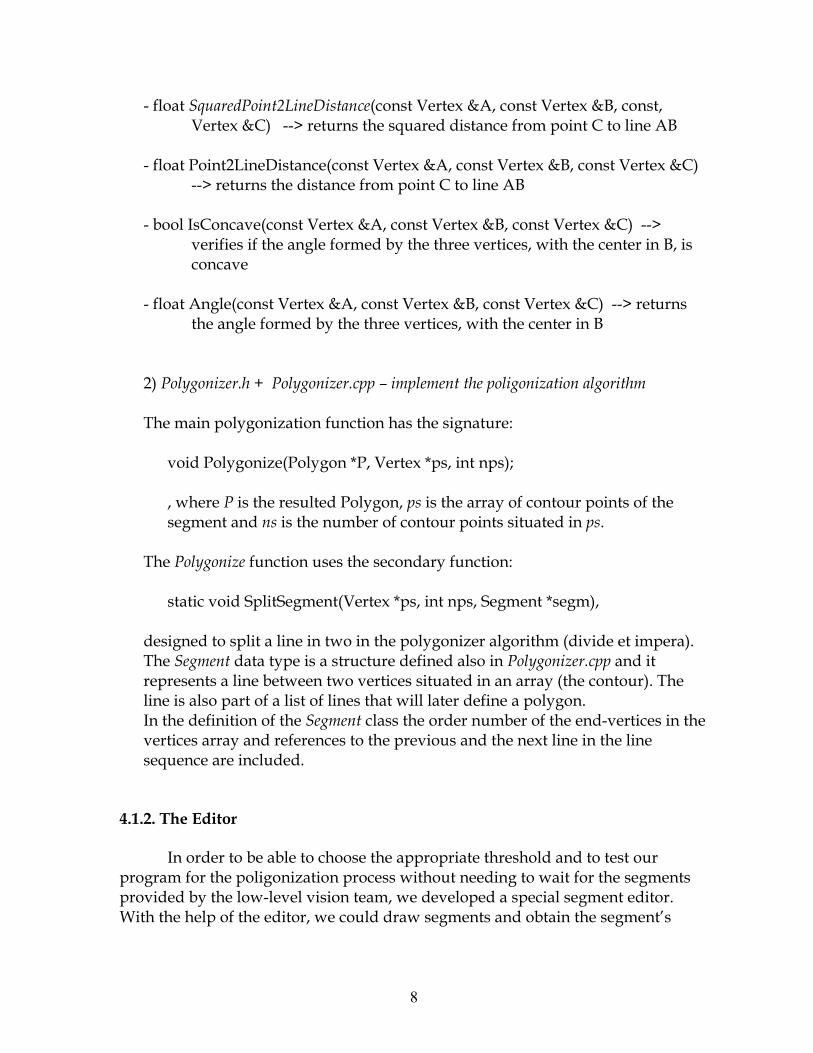
� �
%��� ����−����+��������.������<� ����≅��(�Ι∀!�� ����≅��(�Ι/!�� ���!�≅��(�Ι∃=���%%Χ������������ϑ�������������� ��� ���∃�� ����∀/�
�%��� ���Α ��4Η�0�����<� ����≅��(�Ι∀!�� ����≅��(�Ι/!�� ����≅��(�Ι∃=��
%%Χ�������������������� ��� ���∃�� ����∀/��
%�� ����∃ ����<� ����≅��(�Ι∀!�� ����≅��(�Ι/!�� ����≅��(�Ι∃=��%%Χ����������������� �������������������!���������������/!���� �������
������%��� ���∀���<� ����≅��(�Ι∀!�� ����≅��(�Ι/!�� ����≅��(�Ι∃=��%%Χ����������������� �������������������!���������������/�
��
4=�+�������/� ��∗��+�������/� � �∃��� �������� �������/�����������������
�������� ��� �.�� ������� ����������������∗���� � ��Α ��� �.<Α ��� ��ΚΑ!�≅��(�Κ��!�������=?��
!�����+�������������Α ��� �!� ������������� ��� �� ���� ���� ����������������������������� ��� �� ���� ������������� ���
����+�������/������ ����������� ����������� �∗�
�������� �����������<≅��(�Κ��!�������!�������Κ���=!�
�������� ��������������� ������� ��� �.����� �����<����������=����������������������������������������� ���+�������/� � ��������������������������� �������������������������<���� �� ��=������������� ������ �������� ��������������������������� ��� ������������� �� �������������������� ���������� �������%����������������������������������� ������� �����������(��������������ϑ���������������
��:4:�:6−�<2����
��� ����� �������� ��� ��������� ���������� �������� ����� ���
�� ������ ������ �� �.�� ���� ������� ��������� ������ �������������� ����������� �%������ �����!������ ������������������� ���3���������� ������� �!���� �������������������� �������������:��
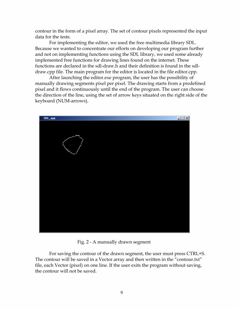
� ��
� �� ��������� ��� �����(��������������� ��� �� ����(������������������������� ������������
> ���������������� �!�����������������������������0��/�������������� �� �������� ����� ���� ����� ���� ����� ����������������� �� ���������������� ������������0�������!�������� ������������������������� ���� �������������� ���� ��������������������� ���������������������%������������������� ����� ������������%���������������������� ������ ������� ����� ��������������� ��������
∀������������������ ��(��� ����!���������������� ������� ��������������������������(������(���������������������� ������������(���������� ���� ���� ���������������� ������� ������������������� ��������� �� �������!������������ ����� �� ���������� ������������� ����� �� ����<Λ,Ε%��� ��=����
��
>���4�%�∀�����������������������
> ������������ �� ��� ����������������!������������������∃�#ΗΜ������� �� ������������������≅�� ����������������������������� �� ����(�����!�����≅�� ��<�(�=� �� ����������������(�������� �������� ��������!����� �� �������� ����������
�
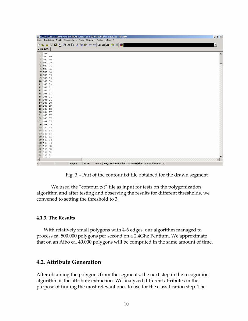
� ���
�
��� >���6�Ν�Α���� ������ �� ����(����� ������� ������������������3���������� �� ����(��������������� ������� ������ ��� �.�� ��
��� ������������������������ ������������������ �������������� ���!���� ������ ��������������� ���� �6��
�
��:4:∃:6−�+������
�3������������������ ��� �������)%∋����!� ������ ������������� �
�� ��������955�555�� ��� �������� ��� ����4�)1�.�Α������3����� (��������� �����∀� �����)5�555�� ��� ���������� ����������������� ���� ������
��∗�∀��∃���������������������∀���� ����������� ��� ����� �����������!�����(������������� ��� ����� ������������������(����� ���3������.��������������������������� �� ������������ ���������� ���� ����� �������������� ����������
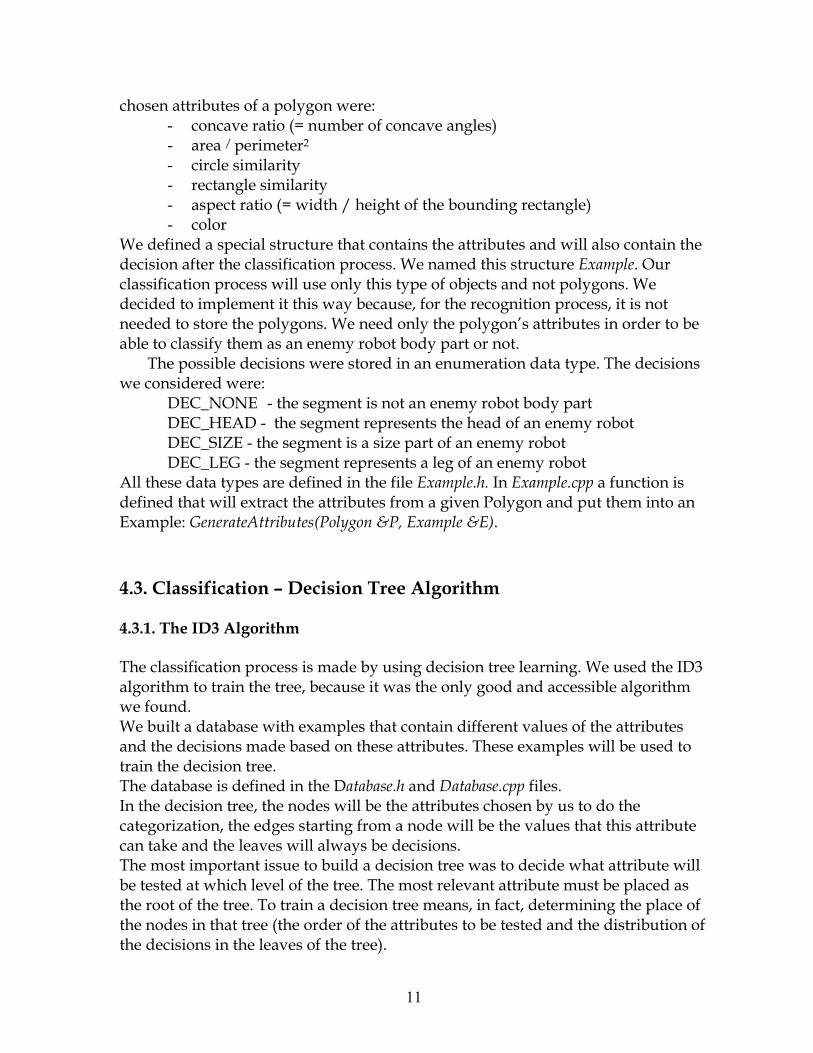
� ���
�� ������������ ����� ��� ����∗��%� � �������� �<Ο������� ��� ����������=�%� �������������%� ��������������%� ����������������%� ��������� �<Ο������8������ ������ �������������=�%� � � ��
3����������������������������� ����������������������������� �� ����������� ������������������� ���� �����3�������������������0,�� ���&������������ ���� ����������� ������������ �� �2��������� ��� ��� ����3������� �����������������������!�� ������� ��� ���� ���!������ ������� ��� ������ ��� ����3���� �������� ��� �:������������� ����� �������� ������������������������ � ��� �������� ��� ���
����� �������� �������� �������������� ������������������ ������ ��������∗�
� 07∃ΦΛ&Λ7��%������������� ���������� � ��� ��������� 07∃Φ+7∀0�%�������������������������� ���������� � ��� 07∃Φ��Π7�%���������������.������ ���������� � ��� 07∃ΦΗ71�%����������������������� ���������� � ��
∀���������������������������������0,�� � � ����0,�� � � �������� ������������������(�������������������� ��������Α ��� ���������������� ����7(����∗�!����1��������2+�������3+��0,�� ��304��
��∗����������(�������0�1�������!����∃�����# ��:∃:4:6−�>?∃9������−�
������������ ���� ��������������������� �������������3���������06���� ������ �����������!���������������� ����� ����������������� �������� �����3��������������������(������������ ������������������ ������������������������ ������������ ��������������������(����������������� ������������ ������������������������������0������ ������.������ � ����������������� ����!����� ����������������������� ���������� �� �������� �.�� �!������������������ ����� ���������������������������������������� ����������������������������� �������� ����� ����������� ����������� ���������� ����������������������������������������� ������������� �������������������������������������� �� ���������� ����������� ���������!�������!����������������� ������ �������������<��� ���� ��������������� ���������������������� �� �������� ������������� �������=��
� ���
� �������� ���� ���������������������� �����<��������� ��������=!�����06���� ����������� �������∗�5�����������!��������0���� � ����7��� ���������������������� ������� ��(���������������� ���� ��1�������������ϑ������� ������������ ���� ���������������������� ������� ��(�������1���������� ��(�����!������� �.�� ��∃��������� ���<��� ��=��������!�Ο�!������� � �� ��� ������������� ��������� ������� ��(�����!�������� �� ���:����� ��������� �� ���∗��� � 7��� ��<�=�Ο�Θ�%���� ��<��=�!�Ο�!��������� ���� ��1���� �������������∀������ ���������� ������(�������∗��� 1���<�!∀=�Ο�7��� ��<�=�%�Θ�<Ρ��Ρ8Ρ�Ρ=�7��� ��<��=�!���������Σ�≅����<∀=����������������� ��(����������∀��������������������.�������������� �����!��� ��� ���!���� ������������ ���������������� ���� ��1����������7��� �������� ������� ��(������������������������ �� ������06���� ������∗��1�������� ��(�����!��!����� �.�������� ������!����∗�����∃� ������ ��� ��� �������������!�∀!�������� ������������� ���� ���� ������������� �����4��> ������������������∀������ �������� !����������������� ������ ����6��> ��������������� ��∀�� ���� ������ �������!�����������������∗��
•� ������������!��� ��������� ���������������� ���������� ���(�������� ���!������������������������ ������ �������������������������
•� ������� ������ ����(�������� �������� ����!���������������������� ������ �������������������������
•� &�����!��� ��∀��� �������� ���������������������������� �� ������������������ ���������� ����!���������������������������������� ������� ��������� ���������� ���� ���� ������������� ������������� ����������������������<�� ��4=!��������������������������������� ������������������������������� �������
������ ��������������������������������������������(������!� �������� ������������������������(������������������ �� �����0�� ������������� ���������.������∀� ����������06�∀�� �������������������.������∀� � ��������∀����5.6���� ��������������06���� ������������#���������� ����� ���������������������!�� ������ �.������(���������∀�����5.6������ ������������ ����

� ���
� �����!�� �������������� ��������������� �.�� ���� �����������#���������� ������������������∀� �� ������� ��� ���� �����
�
�:∃:�:(������,9���2���.�����������&������������� �� ���� ��������������������0�� ������������
�� �����!��������������������� ��� ������������������������������������������������������������������������������(������������������� ��� �� ����������� �.����(�������������� ������������������������������� ��������������������� ��� �������
��������� ���� ���� ���� �������������������������� ������ ���� ������� ���� ���������� ��������������� ������� ������������� ������������������� ��%������� ���� �!���������� �������������������������� ������� ������������ ����� ���� ��������������������!������ ������ ������� �������� ���������������∗����������� ���������.��
3��� ������� ������ �∗���������> ���������� ��������������������+������ �������+������ � ������������������� �������� ������ ����������������
∗�∗���� �(��� �1����!∋����%�� �0��#��!����� ������∋��
�:�:4:8��−��������
�������������������������4%��� ��������������� �������������� �������� �:������������
��������∆������≅Χ�������≅�� �4��������� ����� ������ ������������������������� �!���������� �!�
�������� �!���� �!����� �!�� ����� �!������� �� �!�� ����.�� �!������������������������ �� ����� ����
�:�:�:1���
������������������� ������ �������� ��������������������������������������� ��������������������������� ��������������������������������������������� ������������������
��������∆�������Χ�������Η��?�
� ���
�� � �� ���������� ��������������:���� ��� ������∗������ ������� �!����� ��������� �� �������!������������������������� �����������
∀������ ������� ������� ���������∗�������Α ���������� ��� ��������������� ������������������������������������������ ������ ������� ����
���
−��2�������� ������� ������� �����������������������������!����� ������� ���� ����!�
����� �������������������� �������� ���������∗��%�∃�Ν�Α� ����∗�/�����&���� ��!�Ε� ���Η� ��%�������� �� ����������������������������������������(����� ���� ����%��>������ ������� ��� ������������ �������
��
.��1���������(����#������ ��� ��������.����������
> ������� ������������������������������������������������������������ ������3����������������� ������� ��!��������������� ��������������� ���� ����
�
.�∀���%��(����#��(����������������������∋������ ������(��������3������� ������������������������������������������� ������
�������������� �!���������������������������� �� ���������� �������� �������������∀������� ����������� ��� ���� �������� �����������������������������!������������ ��� �����������������> ���������������������������������� ��������������������������������� ��� ���������!�������� �� �����1,�������������������������� ������� ������������������<������ �=� �������������
∀���������������� �!��������������������� �� ��������������������������������������� �������� ������������
� ���
.�������������������������������0��#������������(��#���������������#������ �
�> ������� ������������������ ��������� ������������� �����
���������������������� ����������������������� ���������� �� ����� ���.�� ���
���
3���(���������=�����∗88������ ���� ���%������8 �� �8�����8��59% �2���� ��� �������4=�����∗88����� �������� 8Τ���8������8�46�8����������������� �������������������������������� ����������� ������������������ !∀�#�∃��%�
��!%%��&!∋�(��)������
�
������∗+,,∋∋∋���−��.���)����/��.0��1��!,23∃,���!4�∗�∗56���!��7��0�6�∗,���!4���.,�
�
������∗+,,∋∋∋���0�6�∗���1,�
�
�
�
�
����������� ������ ����������������������� ���������������� !�������"�#�����$ ������%&�����
'��(���)*�������+*�������������,��-./�0����10���2'����3
'��(�������1������)������������� ��������� �
-�������*������������1
0�����4�����
��,+0����������5���)
&��������6�27������������.�������8$��$3����� ��1��27������������.������$#�#��3
�'��(���*�����'�����
9��,��)����� ��1��
��

� ��
� ��
���������
�
8:5,�����������������,������1��������::::::::::::::::::::::::: ������������������������������������������������������������������������������������������������������������ �������� �������������������������������������������������������� ������� ���������������������� �����!�������������������������������������������������������������� �
�
�:5,�������1��������������;�1�,���������� :::::::::::::::::: �������"���� �������# ����������������������������������������������������������������������������� $�������"���������������������������������������������������������������������������������������������� %�������"���&���������'������������� ��������������������������������������������������������� ���
�
#:������<��������� :::::::::::::::::::::::::::::::::::::::::::::::::::::::::::::::: 8�������"������(���������������������������������������������������������������������������� ���������&���#������)����������������������������������������������������#�����������������#� ����������������������������������������������������������������������� ������������������������������������������������������������������������������������������������������������ ��������&����������������������#������� ��������������������������������������������������� �����$������������������ �����!������������������������������������������������������������ �����*�������������#���+�#����������)�������� �������������������������������������� �����,����������������������������&���-.���������������������������������������������� ��
�
�:*�����������������������1�1��,� ������<��=��������� :::::::::::::::::::::::::::::::::::::::::::::::::::::::::::::::::::::::::::::::: 8����������.������#���������//$������������� ������������������������������ �����������.����//$�������0� ���������������������������������������������������������������� ��
�
�:*��������� :::::::::::::::::::::::::::::::::::::::::::::::::::::::::::::::::::::::::::: 8�
� ��
8:5,�����������������,������1��������&������������� ���� ��������#������1�������!�������1��0��������������������+������������1��������������������������������������������2���3��
8:8�'������
�
��������������������������������1������������������!����������������������&����������� ��� ����������������� �� ���� ��� �)�#������ ���1���� ���� ��� ����� ������������#��������#��������������)�#�����1�����������!�������1����#��"����1�����������������#�0����������������������������������������1�����������������������!�������������������)�#�����������������������4�������������������������������#�����������#����������������������������������������������������������������������������������������������������������������
8:�&�>����,������������������%���������1��������������
�
&�� ����������� ���� ������ ��#������1������������� ����������������� ��� �#���#������� �������#������1�������������������)�����������������������"����1���������������#����� ����������� ���������� ���� �� ��������� ��#���� ���� ���� �������� ���#�������� ����������� �)�#���� -� ��#������ ����� ����� ��� ������ ���� ��������� ������"�����#�������#����1��������������������������������������1����������������������� ��� �#��� ���#� ����� ������ "��� ������� ��#������ �#��� 1����� ����� �������������������������#'�� �����������������������1�������+������������������������������ �� ��������� ��#����� 5��� ���� ������� ��#����� ���� ����������� 1����� �������#��������� ��������� ���� ���������� ��� ���� �������� "��� �����1����� ����� �������� ��� ������� �� �������� ���#� ���� ����� �+�������� ��� ���� ���������� ��+��� �����+�����������+�������������!��������
8:#-�������*����0�����4�����
���� ���� ������ ��#������ 1�� ����������� ����� ��� ������ ��� ���� �������� ����������������#�� ���� ����������� ��� ���� ��������� �������� "��� ������� ����� ��� �����������#� ��������� ��� ����� ������!�� ���� ������!��� �������� 4�� ��#��� ����#���#����������������!���������������������������������#��������
�
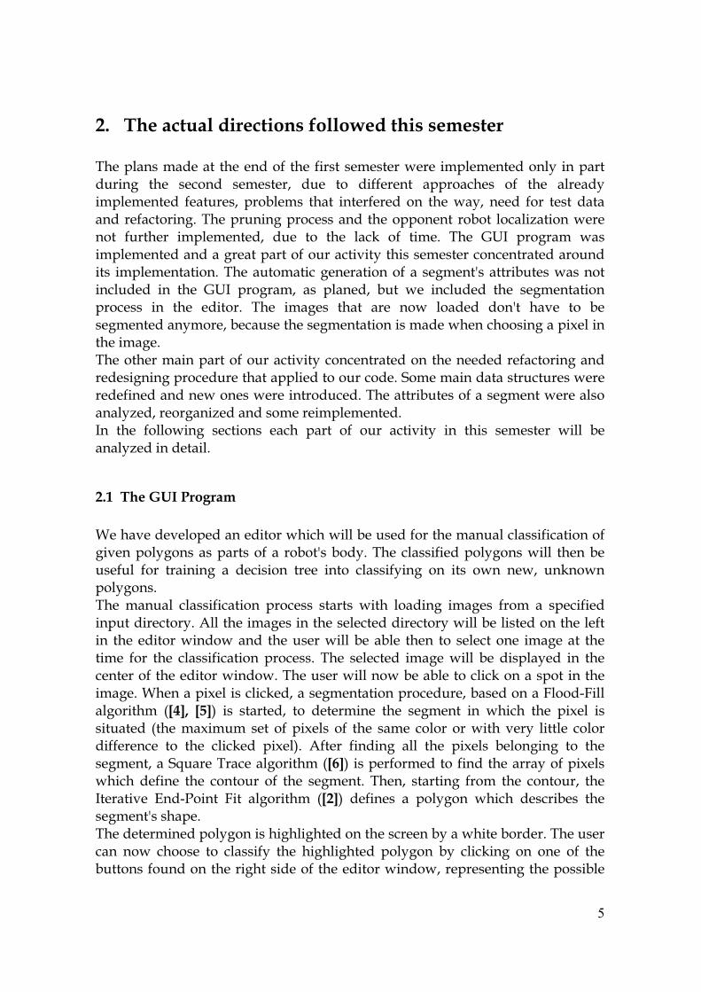
� ��
�:5,�������1��������������;�1�,�����������"���������#������� ����������� ������������#������1�����#���#����������� �������������� ���� ������� ��#������� ���� ��� ���������� ����������� ��� ���� ���������#���#������ ���������� ������#�� ����� ����������� ��� ����1���� ����� ���� ����� ���������������������"���������������������� ������������������� ������!������1�������� �������� �#���#������� ���� ��� ���� ���0� ��� ��#��� "��� � �� �����#� 1����#���#���������������������������������+�����������#������������������������������ �#���#����������"�������#�������������������� ��#���'�������������1���������������� ��� ���� � �� �����#�� ��� �������� ���� 1�� ��������� ���� ��#����������������� ��� ���� �������� "��� �#���� ����� ���� ��1� ������� ���'�� ��+�� ��� �����#���������#�������������������#������������#����1����������������)�����������#����"���������#��������������������+��������������������������������������������������������������������������������������������6�#��#��������������������1��������������������1������1����������������"���������������������#����1��������������!�����������!���������#�����#���#����������� ���� �����1��� ��������� ����� ����� ��� ���� ����+���� ��� ����� ��#������ 1���� ��������!���������������
�:85,�&�>'������
4����+����+�����������������1�����1��������������������#�������������������������+������������������������� �����'��������"����������������������1���� ��������������� ���� �������� �� ��������� ����� ����� ����������� ��� ���� �1�� ��1�� ��0��1������������"��� #������ ��������������� �������� ������� 1���� ������� �#���� ���#� �� ���������������������������&��������#������������������������������1����������������������������� �����������1����1����� ���������1������������ ����� ��� ����������� �#������ ������#�� ���� ���� ��������������� ��������� "��� ��������� �#���1���� ��� ���������� ��� �������������������������1����1��"��������1������1����������������0�������������������#����4��������)����������0��������#�������������������������������5����-5�����������#� 7?�@% ?�@8� ��� ��������� ��� �����#���� ���� ��#���� ��� 1����� ���� ��)��� ������������ 7����#�)�#�#� ���� ��� ��)���� ��� ���� ��#�� ������ ���1���� +���� ������� ����������������� ��� ���� ����0��� ��)��8�� &����� ������� ���� ���� ��)���� �������� ��� ������#�������69�����"������������#�7?A@8� ���������#��������������������������)����1����� ������� ���� �������� ��� ���� ��#����� "����� �������� ���#� ���� ��������� �����������+�� :��-������ 5��� �������#� 7?�@8� �������� �� ������� 1����� ���������� ������#���'����������"��������#��������������������������������������������1�������������"������������ ��1� ������� ��� ��������� ���� ���������� ������� ��� ����0��� ��� ���� ��� �������������������������������������������������1����1���������������������������
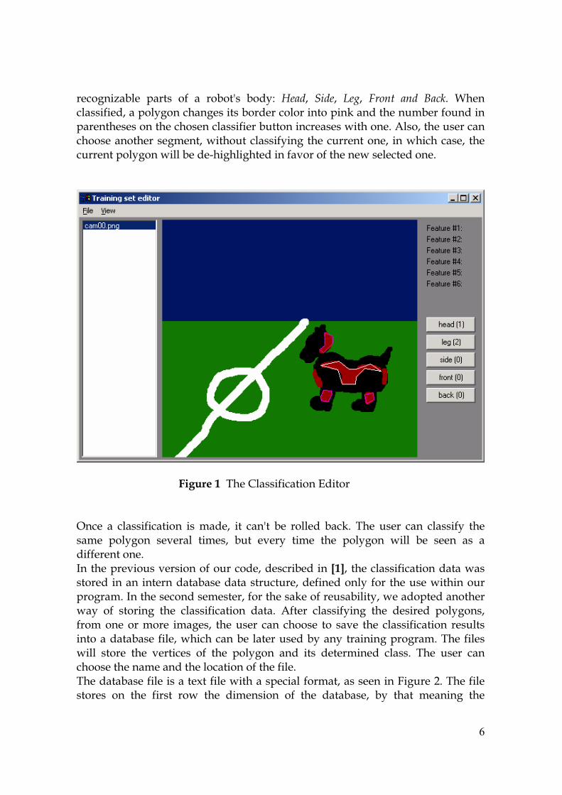
� ��
������!����� ������ ��� �� �����'�� ����3� � ��� ��� � � �� ����� ��� ���� 4���������������������������������������������������������0�����������#�������������������������������������������������������������������1��������&�����������������������������������#�����1����������������������������������� ���1����������� �������������������1���������-���������������+������������1�����������������
��� � � ������8"���.��������������:������������� �� ��������������� ���#����� ��� ���'�� ��� ������� ���0�� "��� ����� ���� ��������� ������#�� ������� ��+����� ��#���� ���� �+���� ��#�� ���� ������� 1���� ��� ����� ��� ���������������������������+�����+���������������������������������?8@�� ������������������������1����������������������������������������������������������������� ��������1���������������#������������������#�����������������0������������������1������������������1��� ��� ������� ���� ��������������� ������ &����� ����������� ���� �������� ������������#��������#���� �#����� ��������� ���� ������� ��� ��+�� ���� ��������������� ������������������������������1������������ �������������������������������#��"���������1���� ������ ���� +�������� ��� ���� ������� ���� ���� �����#����� ������� "��� ����� �����������������#��������������������������������"������������������������)�������1�����������������#���������������5��������"��������������� ��� ���� ������ ��1� ���� ��#������� ��� ���� ���������� ��� ����� #������ ����
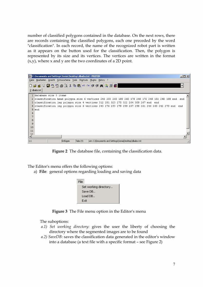
� ��
��#��������������������������������������������������������������)����1������������� �������� ���������� ���� �������������������� ��������������������� ����1����;��������������;�� ����������������������#���������������!�������������� ���1���������� ��� �������� ��� ���� ������� ����� ���� ���� ���������������� "����� ���� ������� ��������������� ��� ���� ��!�� ���� ���� +��������� "��� +�������� ���� 1������� ��� ���� ���#���7)��8��1�����)����������������1��������������������<����������
��� � ��������"�������������������������������������������������������"���:�����'��#��������������������1����������3�
�8����3��������������������������������������+���������
��������#�"���5����#������������������:�����'��#����
���� ������������ "�������������3�
���� � � ������� ��� ����� �+��� ���� ����� ���� �������� ��� �������� ��������������1�����������#�������#�������������������
������� ������+�������������������������������������������������'��1����1�����������������7����)�������1������������������#���(�����5������8�

� ��
��������������������������������������������#�����)���������������7����)������� ����� ��������� ���#��� (� ����5������8��"����1���� ��������� ����������1������#�������������)����������������1�������������������1������
�� �!"����)��������������������#��������8����;3������������������ � �
���������"���=��1�#������������������:�����'��#���� �
�� "�������������3�� #���$��%"����������������������������#�������������#�����!��
#���$��%"��#����������������������������������������������������#����"���������������������������������������#������0���1����������������������������������������������������������������������������#������������������#�����
�
�:�5,�*����������
&�� ���� �������� ��� ���� ������� ��#������ 1�� �����!��� ���� ������� ����� ���������������������#�������������������������������� ��������������������!������������� ���� �����!������� "����� ���� ��#�� #�2��� ������� ��� ���� ����� ���#� �������#������� 1����� �������� ��� �1�� ��+���3� ���� �����!������ ���� ���� �������� ��� ����������5��#����������!�����������������+��1�����������1������2�������������������������� 6�#�� ��1� ������������ 1���� ��������� ���� ��������� ��� ��#�� ������ 1�������������1�������1���������������������#����������#�+����>�2�������������0��������������������#���#����������������������������&#�������������������#������������������������1�������������������������������������������"��������������������������������������������1�����������������������������#�������������1���1����������������������������������������������������������������� ����
"��� ���������� ��� ���� #���� ���������� ������� �������������� "��� ����� ��� ��1������!�����������������������������������������������������#���#������"������������������������������������������������������������������3��������"������������������1)��"����������������#�������������������������������#���������������"����������������������#�����������������������9�������������������������������#���������������������"����������������#�����������������3�
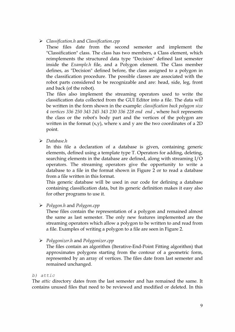
� �
�� &'�((�)�������������&'�((�)���������"����� ������ ����� ���#� ���� ������� ��#������ ���� �#���#���� ����;.�������������;��������"��������������1��#�#��������.��������#�����1��������#���#����� ���� ����������� ����� ����� ;<�������;� �������� ����� ��#������������� ���� !"�%�' ��� ������ ���� �� ������� ���#����� "��� .����� #�#������������� ��� ;<�������;� �������� �������� ���� ������ �������� ��� �� ������� ������� �������������������������� "������������ �������� ���� �����������1���� ���������� ������ ����������� ��� ��� ������!����� ���� ���3� ������ ������ ���� �������������0�7������������8���"��� ������ ����� �#���#���� ���� �����#��� ���������� ����� ��� 1����� �������������������������������������#������ ��:�������������������"��������1�������1�����������������#����1����������)�#���3�'�((�)������#����'����(�* � ��� (��+�,-� �� ,� ���-��+��. �� �� ��1�����#����������������� ������ ��� ���� �����'�� ����� ����� ���� ���� +�������� ��� ���� ������� ����1�����������������#���7)��8��1�����)����������������1��������������������<���������
�� ����#�( ����� ����� ����� �� ������������ ��� �� ��������� ��� �+���� ���������� ����������#�����������������������#�����������"��������������������������������������������#���������������������������������������1���������#����?������������� "��� �����#��� ���������� �+�� ���� ������������ ��� 1����� ����������� ��� �� ����� ��� ���� ���#��� ���1�� ���5����� ����� ��� �������������������#��������1������������������#�����"���� ������� ��������� 1���� ��� ����� ��� ���� ����� ���� �������� �� ������������������������������������������������������������������#�0�������������������������������#�������������
��� ��'������������'�������
"����� �������������� �������������������������������������#��������#�������� ��#�� ��� ����� ��#������� "��� ����� ��1� ��������� �#���#������ ���� ���������#�������������1���������1����������������1����������������������#���������:)�#��������1�������������������������������������5��������
��� ��'�����* ���������'�����* ����
"���������������������������#�7�������+�-:��-������5�������������#8�����������)�#����� �������� �������� ���#� ���� �������� ��� �� ��#������ ���#�����������������������������+���������"�����������������#��������#������������#����������������
����� �����
"��� ����� ���������� ������ ���#� ���� ����� ��#������ ���� ���� ��#������ ���� ��#��� �������������������������������������������+��1�������#�������������������� ��������
� ��
����������������������������#���������������7�����������������1����������1���+�����������������+������#8���������������#���������#���#���������������������1�������������#������������#��"��#�����������������
"���/��'(������������#���������������� ��� ��������� ������#������������ ��������������������������0��+������������������
"�����������1������������������������������������������������������������������������������������#�������#����
�� � �(���/� ������ �(���/� ���@���� ��� �#���#������ ���� <�������� "���� ���������� ���� ���� ������������������� ��� ���� ��������� �������� ���� ���������� ���� ������ "��� ������ ��+����#�����������������������#�����#��������#�������"���������������#�����������������������������������������������#��������������#������������1���������������
��� � ���� (������� ���� (����
���������������#��������������!"�%�' ���������������������������������������������������;&��������;�1����+����"��������������1���������������������������������'�� ���������� ����������� ��� ��� �#�������� ���� ���� ������������������������"������������������������������������'�����7��0��&6�:."A�&"��8���������#�)�#�#��������+�������������������������7����8�����������������������������&���� ���!"�%�' ���� ��� ���������&��������-��1������������ �������&����������1�����������������������������������������������������������������������������������������������#�������1�����������������������������������������������#�������������� ������ ��� ������2���-���������#�������"���� �������� ��� �����1�� ���+�� #��������� ������� ��� ���� ������ ;5�������;�� ��� ��������� ���� ���������������������������������������������������������7��������8������������������� ���������� �� ���� ��� ������� +������ ����������� ��� ���� ���������� &�������� ����� ��� �����9������� �� �������������� 5�������� ��2����� "��� ������;5�������;� ��������� �+��� ��� ��������� ���� ���� �)��������� ��� ���� ����������'�+�������������+��������������������������0�������������<�����������������������#�������������1�����������������������1��������������������+���������������#����������������
��� �������� ������������� ���
"��� ������ �������� ��� ���� �1�� ������� ;���������;�� ��� ���� ��2���-�����������������������������������������������:)�#��������������������#�������������!"�%�' ��� ������ ��� ���� �1�� #�#����3� �� .�������������� 7������� B� .����8�
� �
���#����������5����������#�����"�����������������������)�#���������������������� ��� �������� ���� ��������� ������ ��� ���� ��������� ��������� ����� ��������������� 7��������8�1������� ������� ��� �������-������������ ����+������ �������0�������������������������������������������������� �0�� ������ ����� ������ #���������� ���� ���������� ������ ����� �#���#����������#������������������?�������������������������
��� ������#����������������
"��� ;�����<C;� ������ ��� �������� ��� ������ �1�� ������� ��� ��� ��������� ���� ����<�������� ������ �������� ��� ���� ������ ��#������� ���� ���� �������� ���������������!�����������������������������������1�����������������<�������������������������������#�������1������������������������#���#����������������1���������#����#�����������6�����������������;�����<C;��1���������������������������1�����������������#������������������������������#������������������������������#�( �����;�����<C;� ���� ����� �����#��� ����������� ��0�� #���� ��� ���� ��������#������������+���
�������
"���� ��1� ���������� ��������� ���� ���� ������ ����� �#���#���� ���� �����������������������������#��C������������������������������������������1�������������#�������������������������������������������������������1)��"���������������������������#������������������������������������������?$@��
�:#5,�9���������B*�1���������
�&�����������������������������������������'��#���#����������1������������#�������������������� 1���� ���� ���+������� ��� ������� ��� �� ��������� ���#� ���� ������� ��� ������������ ��� ������� ��� ����������� 5��� �)�#����� .������ 6�#�������� ���� ���������6�#�������� ���� +���� ����� ��� ������� ��� �� ��������� ���#� ���� ��9����� �� ������������#������������������������#�������������������������"����������������������������������������������������� ���� ������� ���� ������������3�����' ��� "���0�(� ����������%# ��)� ��� (������%���� ((��1��' &��� "���� ��� �������� ��� ���������+�������������������������� ��� �������+����������+��������"��������+��������1������������������#���������������#�����������������'�������+���������4�������������������������������������������������1������������������������#����������������������������1�����0�������������������������������#����������+�)����������������������' ��� "�������������������������������#������������+�����������#�������#����������+�)��������
� ��
&�����������������#����������0�������������������������������������������������#��������������������1���������������1������1����������������������1���������������������' ��� "����
-� ���������+�)�������(���������+��������D�������������� ���� �����C8D-� ���������+�)�������(���������+��������D������������ ���� �����C�D-� ���������������������� ���� �����C#:�
�&������� ������'�� ���������� ����������� 1��� 1(� � 2������ "��� ���������� 1���������� ����� ��#������ ����� ���� ��� ������� ��� ���� 1����?������ ������� "��� ��������������������1����+����������#������������3�
-� �����$�E�������FD�1�������(� ������D�/G�-� ���������HD���$�1�������(� ������D��G�-� �������������������7������I�1����8���(� ������3����
"���4�%# ��)5 ��� (��������������������������������������������������������"������������� 1��� ������� ����� ����� ��#������� ������ �� ������ ��������� ��� ���� ����������������������"����������������������������������������������������3�
-� ���������#�����������������'��+�����������FD������HD*����%# ��)� ��� (3-6
-� ���������#�����������������'��+�����������$����%# ��)� ��� (3�6�-� ��������������������������%# ��)� ��� (3���
�"��� ������ ���������� ������������&�%���� ((�� ������� ��� ���� ����?�������� ������� ��������'����+���������������������������������������+����������������������9����������� ���� �������� ��� �������� ���� ���9����� ������������ 1�� �����!��� ������+��� ������������������������������������������������������?�@��4�������������������������1� ����������� ��� ��� �+�������� ��� ���� ��������������� ��������� .������� ��������������� ��9������� ��������� �� �����#����� ��������� ���� ����������� �������� ��������9�������1������� �� ����������� �#����� ��� ����� ���� ������� ���� �����#����������������������������������+��������������������������������������+�����������1���
#:������<����������&������� #���� ��� ���� ����� ���� ���� ����������� ��� ���� ��������� ������� ����#���#������� ������ ���� ������ ��#�� ������ ����� ����� ��+����#���� ��� �������� "���������������������#����������#���������������1������������������1����3��
� ��
#:85������+�,����1�������1���
�5��� ������� ���� �������#�� ���� ���� �����#������ ���� ���� ������� ����������� ���������� ��������� ������������ �+���1�� ����� �� ������������� �#����� ��� ����� ������ ���1�����#�������#������0������#�����&������#�����
#:�9���������E����������������������1����1����1���������������11�1����������:
�4�� ����� ��� �#���#������ �� �����#� ����� �)������� ����#��������� ���� ����������������������#������������������������)�������������������� ����������7������8������������ ����� ��� ����� ��� 1����� ��� ����� ��� ������!�� ���� ������ ������� �������������������������������������������
#:#'������
�"�������������������������� ��#����������� ���� ���� ���������������������������������������������������������������������!���������������������������6�#��������������� ���� �#���#������������� ��������������� ����������������� �#���#���������������������+�������������������������
�
#:�9��������1�������������������
�4����������0����������������1�������������������������������������������������������������������#�����������������������������������#������������������������������������������������������������#������������� 2������������������������������������������� ���#����������� �����#����� ��������&����� ����.�#��������� �������� ���������������������������������������������#��
�
#:�-�������*����0�����4�����
�&�� ������������� ������)�� ����� ��� �����!��� ���������1������������+��� ��� ���� ��������#������������������#���������//?�//$��������������!����������������������������������'�� ������!�������&�������������������������������������� ����������!������1�������������������
#:A'���������������������1�E��������
�

� ��
&����� ���� ���������� ��#�������� ��� ���� ����� 1���� ��� �������� ���� �������� ����������+����������� ������������1������������������� ����������������������������������������#���+�������#���#�!��������)����������#���"���� �������������������������������������������//�>�!����&���������#������+���������#��������������+�������������������)����������#��#��������������������'�������������������������
�
#:$>�������������1����,�9������1�
�
���� ������ ���� ���� ��� �������� ���� �������������� ���� �����1�� �������� ��� ����&����������4���������������������!��1�����������1����1��������������������
�:*�����������������������1�1��,� ������<��=������������ ���� �����#��� ����� �//?�//$� ���� ��+������� ��� @�#���'�� ���#� ��� &������@�#����<��C��������������������� �1����#������������� �������������� ���03� ���������� �������� ��� ���� ����.��� ���#��� ����� ��� ����������� ���#���� ���� ��������.���������0���J�������
�:8*������&�����-���������'�1������
�"�����������#������������������.������#���������1�����������1��������%����������� �/��� ��� &����� �//$� ��� ���� @���!� K�)����� >����#�5���#� ��� ��������������#�����"�����1���������������L�&�������#�����������������������������#������������#������#����������� ��+���������������#�������1�������@���������������5����������6������"���@�#����<��C����#�������������������9���������������1�����������������"��#�.��������#�6����������������������9�������������������+����������&���� "��#� @�#������ ���#� ���� @�#����� ��+������� ��� C������� ��� ���� ������������ ���� @�#���� <�� C���� 1��� ���� ��� ���� ��������� ��#����������� ����=�������� ������ .��������� 1����� ���� ����� �������� ���� ������� �+���� �/�����������������������#������������������������#�����������������������������������������������7?8�@8��
�:�*������������-��6�
�"�������.����//$����0����������1����������������������L��� J�����//$�������0���J������"���5���� ���� ��������������"��#�� ���#������+��� ����1������"���

� ��
@�#����<��C�����1���1������������ ��� ���� ��#���������� ���� ��#��������#����������������������������������1�����������������������������&��������������������������� ������#��� "���� ���� ������ ������#�� �������� ���� @�#���� <�� C����������� �������� ���� 9������� �������� &�� ���� ��� ��� ��������� ���� �����������#���������������@�#����<��C����������������L���������������������.����������#����������1��������������#�����.�##��������6����#�����������������������������������"�������������������������������������&�#����6��#�.���������1���������������#�������������������#���������������������#�������������������������#������#���������$�������������������������������&������=�������� ����.����������������#�����'�� ��� ���� �)������� �������� ���� #������ ��� ������ ���� ������� ������ ��� ����������������������������������������9�����������������4�����.����//*����C��#�������#��������
�:*����������?8@ 6�����@���������2�����������;7���� ��2 ��������������'�*�����;����������?�@ C�����K��#�����.�#������=������.������������� ��+����������@�#�����
����3??0��-111������#���0����-��#������?I���#���?C=-66-�//$?M5�����
�?#@�� ����<�������:�@��������� ��&'�((�)���������� � 1��'�(�(��J����4�����N�
6�����������K�1�O��0���L,��?�@ J�#���<��5��������������8������������&�%��� �9�����(��&������-4������
����������.�#�������LL���?�@�� >�������&��������9�����(������%%����'��������.��������������C��0���
�LL,��?A@ "�� ��+������� ���������� ���� ������� ���� ���� � ��� ������� .�#������
6�����������������0+������>����������L%��?$@�� 1)��������������3??1)���0������������������?��?F@����3??111������������?G@ ����3??111������������������?��?�//$?��

� ��
?8�@ ����3??111������#���0����-��#������?"�6?����)����P�������D���������?����)���#?��
�?88@� ����3??��#���-�����������������#?��?8�@�� ����3??111������#���0����-��#������?"�6?���0�A���?����)������?8#@� ����3??������#�������?��?8�@� ����3??111��!����?����?���?+��1?4������?��������//$�