Embed Size (px)
Citation preview
Page 1 of 8
HALSTED
STREET BRIDGE
OVER CHICAGO
RIVER NORTH
BRANCH CANAL
DR. SOLIMAN KHUDEIRA,
..PHD, SE, PE
BIOGRAPHY
Dr. Soliman Khudeira, SE, PE is a
Section Chief of Major Projects
with the Chicago Department of
Transportation.
He is an Adjunct Professor at
Illinois Institute of Technology
(IIT), where he teaches
Transportation Facilities Design,
Special Projects, Research
Problems, Special Problems, and
PE and FE/EIT Classes.
He is the Chief Editor of the
Practice Periodicals on Structural
Design and Construction, an
ASCE Journal.
He is a member of the Executive
Board of the Structural Engineers
Association of Illinois.
He received his BS, MS, and PhD
in Civil Engineering-Structures
from Illinois Institute of
Technology, Chicago.
He has over 30 years of
experience in the various
disciplines of civil engineering
including: civil design, structural
analysis & design, surveying, and
construction management.
He is licensed Structural Engineer
and Professional Engineer in
Illinois.
SUMMARY
The Halsted Street Bridge over
the Chicago River was originally
constructed in 1908 as a movable
bridge, providing navigable
waterway. Due to deterioration
and lack of river traffic, it had not
functioned as a movable bridge
for more than 25 years. The
existing bridge had become
structurally obsolete and
functionally deficient.
Different bridge alternatives were
considered and evaluated. A
modern steel tied arch bridge was
eventually selected, due to its cost
effectiveness, superior
aesthetically-pleasing shape and
potential positive economic
impact to the local community.
The new replacement structure is
parabolically-shaped tied arch
bridge. Additionally, two precast
concrete arches located under the
bridge were designed to provide
pedestrian and bicyclists access
for future extension of the
Chicago Riverwalk.
In addition to the major
improvement of bridge
accessibility and openness,
aesthetic enhancements were
incorporated into many elements
of the project, including
architectural lighting and railings.
STAAD 3D FEM model was used
to model the entire bridge.
Additionally, SAP2000 3D FEM
model was created to analyze the
knuckle.
The content of this presentation
focuses on the critical design
elements and introduce the
process of analyzing, design,
detailing and erection of the
Halsted Street steel tied-arch
bridge.
Page 2 of 8
Halsted Street Bridge over Chicago
River North Branch Canal
Keywords
Tied-arch bridge, bascule bridge, tie, floor beam,
strut, hanger, load path, redundancy,
constructability, camber, torsional moment
Abstract
This presentation will discuss the design approach of
the replacement bridge, consisting of the Main Span
Simply Supported Tied-Arch with North and South
Three-Sided Precast Concrete Underpasses, retaining
walls and cofferdams. The original Bridge over the
Chicago River North Branch Canal was constructed
in 1909 as a Bascule Bridge. The existing Bascule
bridge is 300ft long and 60ft wide.
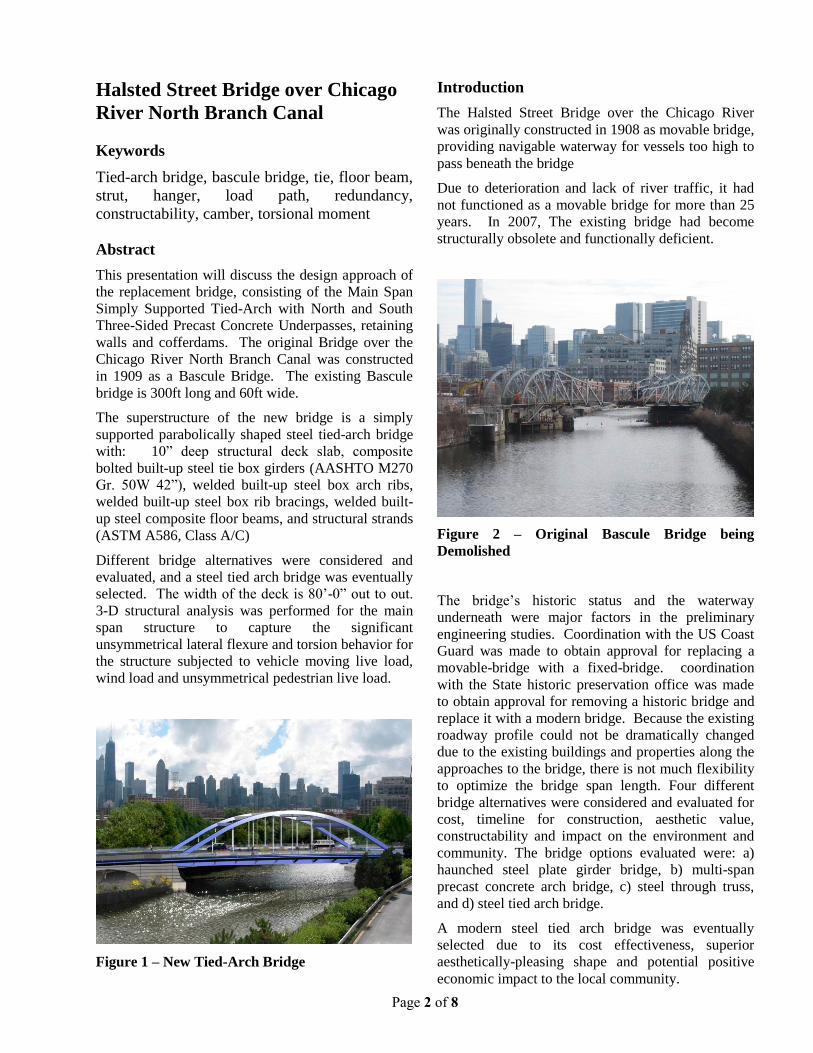
The superstructure of the new bridge is a simply
supported parabolically shaped steel tied-arch bridge
with: 10” deep structural deck slab, composite
bolted built-up steel tie box girders (AASHTO M270
Gr. 50W 42”), welded built-up steel box arch ribs,
welded built-up steel box rib bracings, welded built-
up steel composite floor beams, and structural strands
(ASTM A586, Class A/C)
Different bridge alternatives were considered and
evaluated, and a steel tied arch bridge was eventually
selected. The width of the deck is 80’-0” out to out.
3-D structural analysis was performed for the main
span structure to capture the significant
unsymmetrical lateral flexure and torsion behavior for
the structure subjected to vehicle moving live load,
wind load and unsymmetrical pedestrian live load.
Figure 1 – New Tied-Arch Bridge
Introduction
The Halsted Street Bridge over the Chicago River
was originally constructed in 1908 as movable bridge,
providing navigable waterway for vessels too high to
pass beneath the bridge
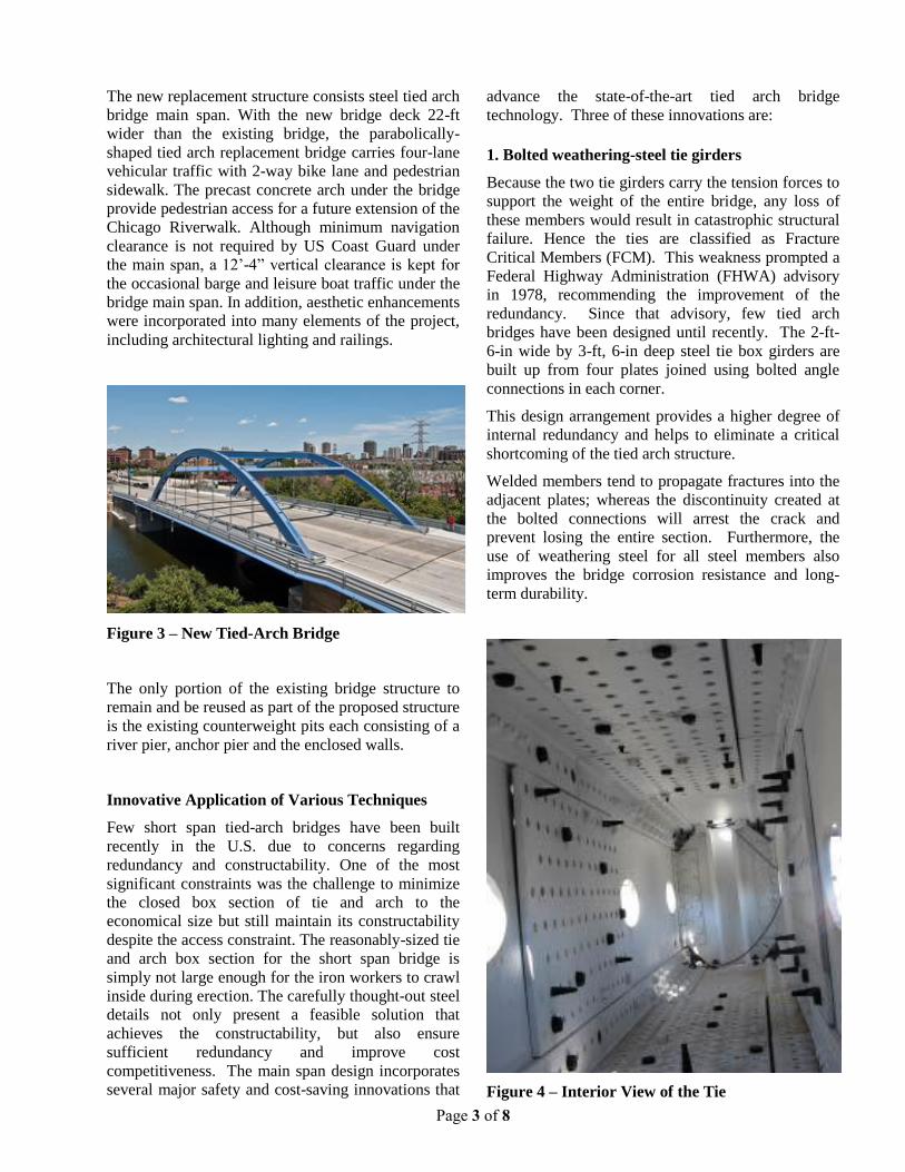
Due to deterioration and lack of river traffic, it had
not functioned as a movable bridge for more than 25
years. In 2007, The existing bridge had become
structurally obsolete and functionally deficient.
Figure 2 – Original Bascule Bridge being
Demolished
The bridge’s historic status and the waterway
underneath were major factors in the preliminary
engineering studies. Coordination with the US Coast
Guard was made to obtain approval for replacing a
movable-bridge with a fixed-bridge. coordination
with the State historic preservation office was made
to obtain approval for removing a historic bridge and
replace it with a modern bridge. Because the existing
roadway profile could not be dramatically changed
due to the existing buildings and properties along the
approaches to the bridge, there is not much flexibility
to optimize the bridge span length. Four different
bridge alternatives were considered and evaluated for
cost, timeline for construction, aesthetic value,
constructability and impact on the environment and
community. The bridge options evaluated were: a)
haunched steel plate girder bridge, b) multi-span
precast concrete arch bridge, c) steel through truss,
and d) steel tied arch bridge.
A modern steel tied arch bridge was eventually
selected due to its cost effectiveness, superior
aesthetically-pleasing shape and potential positive
economic impact to the local community.
Page 3 of 8
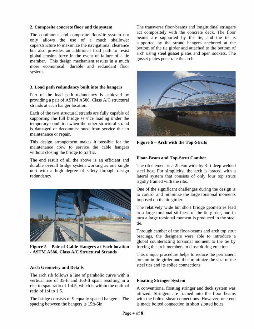
The new replacement structure consists steel tied arch
bridge main span. With the new bridge deck 22-ft
wider than the existing bridge, the parabolically-
shaped tied arch replacement bridge carries four-lane
vehicular traffic with 2-way bike lane and pedestrian
sidewalk. The precast concrete arch under the bridge
provide pedestrian access for a future extension of the
Chicago Riverwalk. Although minimum navigation
clearance is not required by US Coast Guard under
the main span, a 12’-4” vertical clearance is kept for
the occasional barge and leisure boat traffic under the
bridge main span. In addition, aesthetic enhancements
were incorporated into many elements of the project,
including architectural lighting and railings.
Figure 3 – New Tied-Arch Bridge
The only portion of the existing bridge structure to
remain and be reused as part of the proposed structure
is the existing counterweight pits each consisting of a
river pier, anchor pier and the enclosed walls.
Innovative Application of Various Techniques
Few short span tied-arch bridges have been built
recently in the U.S. due to concerns regarding
redundancy and constructability. One of the most
significant constraints was the challenge to minimize
the closed box section of tie and arch to the
economical size but still maintain its constructability
despite the access constraint. The reasonably-sized tie
and arch box section for the short span bridge is
simply not large enough for the iron workers to crawl
inside during erection. The carefully thought-out steel
details not only present a feasible solution that
achieves the constructability, but also ensure
sufficient redundancy and improve cost
competitiveness. The main span design incorporates
several major safety and cost-saving innovations that
advance the state-of-the-art tied arch bridge
technology. Three of these innovations are:
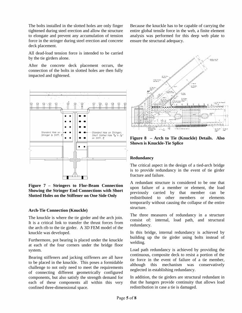
1. Bolted weathering-steel tie girders
Because the two tie girders carry the tension forces to
support the weight of the entire bridge, any loss of
these members would result in catastrophic structural
failure. Hence the ties are classified as Fracture
Critical Members (FCM). This weakness prompted a
Federal Highway Administration (FHWA) advisory
in 1978, recommending the improvement of the
redundancy. Since that advisory, few tied arch
bridges have been designed until recently. The 2-ft-
6-in wide by 3-ft, 6-in deep steel tie box girders are
built up from four plates joined using bolted angle
connections in each corner.
This design arrangement provides a higher degree of
internal redundancy and helps to eliminate a critical
shortcoming of the tied arch structure.
Welded members tend to propagate fractures into the
adjacent plates; whereas the discontinuity created at
the bolted connections will arrest the crack and
prevent losing the entire section. Furthermore, the
use of weathering steel for all steel members also
improves the bridge corrosion resistance and long-
term durability.
Figure 4 – Interior View of the Tie
Page 4 of 8
2. Composite concrete floor and tie system
The continuous and composite floor/tie system not
only allows the use of a much shallower
superstructure to maximize the navigational clearance
but also provides an additional load path to resist
global tension force in the event of failure of a tie
member. This design mechanism results in a much
more economical, durable and redundant floor
system.
3. Load path redundancy built into the hangers
Part of the load path redundancy is achieved by
providing a pair of ASTM A586, Class A/C structural
strands at each hanger location.
Each of the two structural strands are fully capable of
supporting the full bridge service loading under the
temporary condition when the other structural strand
is damaged or decommissioned from service due to
maintenance or repair.
This design arrangement makes it possible for the
maintenance crew to service the cable hangers
without closing the bridge to traffic.
The end result of all the above is an efficient and
durable overall bridge system working as one single
unit with a high degree of safety through design
redundancy.
Figure 5 – Pair of Cable Hangers at Each location
- ASTM A586, Class A/C Structural Strands
Arch Geometry and Details
The arch rib follows a line of parabolic curve with a
vertical rise of 35-ft and 160-ft span, resulting in a
rise-to-span ratio of 1:4.5, which is within the optimal
ratio of 1:4 to 1:5.
The bridge consists of 9 equally spaced hangers. The
spacing between the hangers is 15ft-6in.
The transverse floor-beams and longitudinal stringers
act compositely with the concrete deck. The floor
beams are supported by the tie, and the tie is
supported by the strand hangers anchored at the
bottom of the tie girder and attached to the bottom of
arch using steel gusset plates and open sockets. The
gusset plates penetrate the arch.
Figure 6 – Arch with the Top-Struts
Floor-Beam and Top-Strut Camber
The rib element is a 2ft-6in wide by 3-ft deep welded
steel box. For simplicity, the arch is braced with a
lateral system that consists of only four top struts
rigidly framed with the ribs.
One of the significant challenges during the design is
to control and minimize the large torsional moments
imposed on the tie girder.
The relatively wide but short bridge geometries lead
to a large torsional stiffness of the tie girder, and in
turn a large torsional moment is produced in the steel
tie.
Through camber of the floor-beams and arch top strut
bracings, the designers were able to introduce a
global counteracting torsional moment to the tie by
forcing the arch members to close during erection.
This unique procedure helps to reduce the permanent
torsion in tie girder and thus minimize the size of the
steel ties and its splice connections.
Floating Stringer System
A conventional floating stringer and deck system was
utilized. Stringers are framed into the floor beams
with the bolted shear connections. However, one end
is made bolted connection in short slotted holes.
Page 5 of 8
The bolts installed in the slotted holes are only finger
tightened during steel erection and allow the structure
to elongate and prevent any accumulation of tension
force in the stringer during steel erection and concrete
deck placement.
All dead-load tension force is intended to be carried
by the tie girders alone.
After the concrete deck placement occurs, the
connection of the bolts in slotted holes are then fully
impacted and tightened.
Figure 7 – Stringers to Flor-Beam Connection
Showing the Stringer End Connections with Short
Slotted Holes on the Stiffener on One Side Only
Arch-Tie Connection (Knuckle)
The knuckle is where the tie girder and the arch join.
It is a critical link to transfer the thrust forces from
the arch rib to the tie girder. A 3D FEM model of the
knuckle was developed.
Furthermore, pot bearing is placed under the knuckle
at each of the four corners under the bridge floor
system.
Bearing stiffeners and jacking stiffeners are all have
to be placed in the knuckle. This poses a formidable
challenge to not only need to meet the requirements
of connecting different geometrically configured
components, but also satisfy the strength demand for
each of these components all within this very
confined three-dimensional space.
Because the knuckle has to be capable of carrying the
entire global tensile force in the web, a finite element
analysis was performed for this deep web plate to
ensure the structural adequacy.
Figure 8 – Arch to Tie (Knuckle) Details. Also
Shown is Knuckle-Tie Splice
Redundancy
The critical aspect in the design of a tied-arch bridge
is to provide redundancy in the event of tie girder
fracture and failure.
A redundant structure is considered to be one that
upon failure of a member or element, the load
previously carried by that member can be
redistributed to other members or elements
temporarily without causing the collapse of the entire
structure.
The three measures of redundancy in a structure
consist of: internal, load path, and structural
redundancy.
In this bridge, internal redundancy is achieved by
building up the tie girder using bolts instead of
welding.
Load path redundancy is achieved by providing the
continuous, composite deck to resist a portion of the
tie force in the event of failure of a tie member,
although this mechanism was conservatively
neglected in establishing redundancy.
In addition, the tie girders are structural redundant in
that the hangers provide continuity that allows load
redistribution in case a tie is damaged.
Page 6 of 8
Thermal Stresses
The bridge was checked for thermal stresses
considering the temperature difference between the
exposed rib and shielded tie under the bridge deck.
The temperature gradient between these two elements
was determined in accordance with the related
AASHTO provisions and modeled in the 3D FEM
modeling. The corresponding load combination was
taken into considerations during analysis.
Generally, if the tie is not shielded under the deck,
then the tie and rib are expanding and contracting in
the same rate in the bridge longitudinal “X” direction,
and, therefore, there is no relative thermal stress
between the tie and rib.
In the bridge transverse direction, the guide
expansion pot bearings provide adequate lateral
movement to accommodate the “Y” direction thermal
relative movement between the superstructure and
bridge abutments. Therefore there is no restraining
force that should be considered in the “Y” direction
In the bridge vertical “Z” direction, the rib vertical
thermal movement is unrestrained. Therefore there is
no restraining stress caused by the bridge thermal
expansion in the bridge vertical direction.
3D FEM Models
SAP2000 3D FEM model was created to analyze the
knuckle. The input forces in the SAP2000 model
were obtained from a separate STAAD 3D FEM
model of the entire bridge. The forces in the knuckle
from the STAAD 3D FEM model are: Fx (axial), Fy
and Fz (shear in two axis directions), Mx (torsional
moment), My and Mz (bending moments along
vertical and horizontal axis)
Constructability
Several major constructability issues were carefully
studied during the Phase II Design:
One of constraints was the challenge to minimize the
closed box section of tie and arch to the economical
size but still maintain its constructability without the
access to the interior of the steel box during erection.
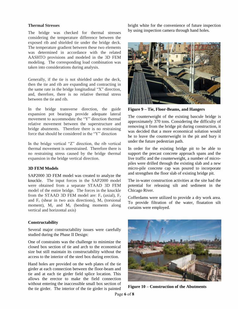
Hand holes are provided on the web plates of the tie
girder at each connection between the floor-beam and
tie and at each tie girder field splice location. This
allows the erector to make the field connection
without entering the inaccessible small box section of
the tie girder. The interior of the tie girder is painted
bright white for the convenience of future inspection
by using inspection camera through hand holes.
Figure 9 – Tie, Floor-Beams, and Hangers
The counterweight of the existing bascule bridge is
approximately 370 tons. Considering the difficulty of
removing it from the bridge pit during construction, it
was decided that a more economical solution would
be to leave the counterweight in the pit and bury it
under the future pedestrian path.
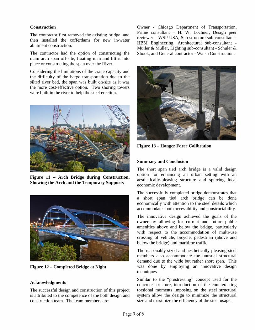
In order for the existing bridge pit to be able to
support the precast concrete approach spans and the
live traffic and the counterweight, a number of micro-
piles were drilled through the existing slab and a new
micro-pile concrete cap was poured to incorporate
and strengthen the floor slab of existing bridge pit.
The in-water construction activities at the site had the
potential for releasing silt and sediment in the
Chicago River.
Cofferdams were utilized to provide a dry work area.
To provide filtration of the water, floatation silt
curtains were employed.
Figure 10 – Construction of the Abutments
Page 7 of 8
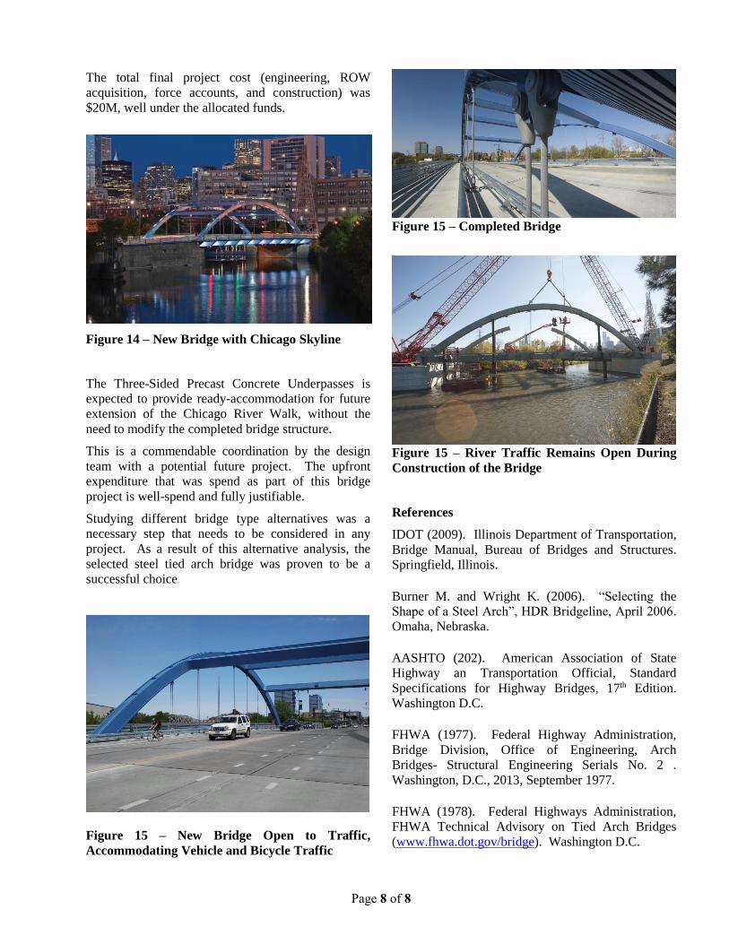
Construction
The contractor first removed the existing bridge, and
then installed the cofferdams for new in-water
abutment construction.
The contractor had the option of constructing the
main arch span off-site, floating it in and lift it into
place or constructing the span over the River.
Considering the limitations of the crane capacity and
the difficulty of the barge transportation due to the
silted river bed, the span was built on-site as it was
the more cost-effective option. Two shoring towers
were built in the river to help the steel erection.
Figure 11 – Arch Bridge during Construction,
Showing the Arch and the Temporary Supports
Figure 12 – Completed Bridge at Night
Acknowledgments
The successful design and construction of this project
is attributed to the competence of the both design and
construction team. The team members are:
Owner - Chicago Department of Transportation,
Prime consultant – H. W. Lochner, Design peer
reviewer – WSP USA, Sub-structure sub-consultant -
HBM Engineering, Architectural sub-consultant -
Muller & Muller, Lighting sub-consultant - Schuler &
Shook, and General contractor - Walsh Construction.
Figure 13 – Hanger Force Calibration
Summary and Conclusion
The short span tied arch bridge is a valid design
option for enhancing an urban setting with an
aesthetically-pleasing structure and spurring local
economic development.
The successfully completed bridge demonstrates that
a short span tied arch bridge can be done
economically with attention to the steel details which
accommodates both accessibility and constructability.
The innovative design achieved the goals of the
owner by allowing for current and future public
amenities above and below the bridge, particularly
with respect to the accommodation of multi-use
crossing of vehicle, bicycle, pedestrian (above and
below the bridge) and maritime traffic.
The reasonably-sized and aesthetically pleasing steel
members also accommodate the unusual structural
demand due to the wide but rather short span. This
was done by employing an innovative design
techniques.
Similar to the “prestressing” concept used for the
concrete structure, introduction of the counteracting
torsional moments imposing on the steel structural
system allow the design to minimize the structural
size and maximize the efficiency of the steel usage.
Page 8 of 8
The total final project cost (engineering, ROW
acquisition, force accounts, and construction) was
$20M, well under the allocated funds.
Figure 14 – New Bridge with Chicago Skyline
The Three-Sided Precast Concrete Underpasses is
expected to provide ready-accommodation for future
extension of the Chicago River Walk, without the
need to modify the completed bridge structure.
This is a commendable coordination by the design
team with a potential future project. The upfront
expenditure that was spend as part of this bridge
project is well-spend and fully justifiable.
Studying different bridge type alternatives was a
necessary step that needs to be considered in any
project. As a result of this alternative analysis, the
selected steel tied arch bridge was proven to be a
successful choice
Figure 15 – New Bridge Open to Traffic,
Accommodating Vehicle and Bicycle Traffic
Figure 15 – Completed Bridge
Figure 15 – River Traffic Remains Open During
Construction of the Bridge
References
IDOT (2009). Illinois Department of Transportation,
Bridge Manual, Bureau of Bridges and Structures.
Springfield, Illinois.
Burner M. and Wright K. (2006). “Selecting the
Shape of a Steel Arch”, HDR Bridgeline, April 2006.
Omaha, Nebraska.
AASHTO (202). American Association of State
Highway an Transportation Official, Standard
Specifications for Highway Bridges, 17th Edition.
Washington D.C.
FHWA (1977). Federal Highway Administration,
Bridge Division, Office of Engineering, Arch
Bridges- Structural Engineering Serials No. 2 .
Washington, D.C., 2013, September 1977.
FHWA (1978). Federal Highways Administration,
FHWA Technical Advisory on Tied Arch Bridges
(www.fhwa.dot.gov/bridge). Washington D.C.