Embed Size (px)
Citation preview
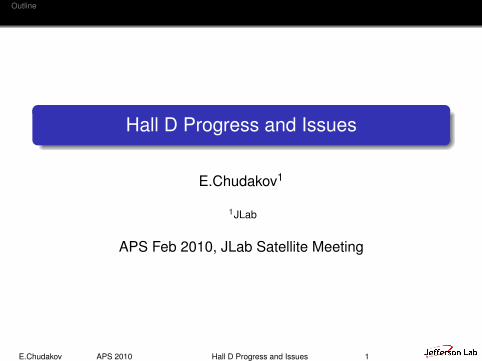
Outline
Hall D Progress and Issues
E.Chudakov1
1JLab
APS Feb 2010, JLab Satellite Meeting
E.Chudakov APS 2010 Hall D Progress and Issues 1
Outline
Outline
1 Hall D Project
2 Hall D Construction
3 Summary
4 Appendix
E.Chudakov APS 2010 Hall D Progress and Issues 2
Outline
Outline
1 Hall D Project
2 Hall D Construction
3 Summary
4 Appendix
E.Chudakov APS 2010 Hall D Progress and Issues 2
Outline
Outline
1 Hall D Project
2 Hall D Construction
3 Summary
4 Appendix
E.Chudakov APS 2010 Hall D Progress and Issues 2

Outline
Outline
1 Hall D Project
2 Hall D Construction
3 Summary
4 Appendix
E.Chudakov APS 2010 Hall D Progress and Issues 2
Hall D Project Hall D Construction Summary Appendix
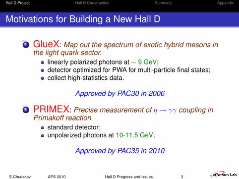
Motivations for Building a New Hall D
1 GlueX: Map out the spectrum of exotic hybrid mesons inthe light quark sector.
linearly polarized photons at ∼ 9 GeV;detector optimized for PWA for multi-particle final states;collect high-statistics data.
Approved by PAC30 in 2006
2 PRIMEX: Precise measurement of η → γγ coupling inPrimakoff reaction
standard detector;unpolarized photons at 10-11.5 GeV;
Approved by PAC35 in 2010
E.Chudakov APS 2010 Hall D Progress and Issues 3
Hall D Project Hall D Construction Summary Appendix
Other Physics Interests
Charm production close to thresholdsCascade resonancesA new workshop in 2010
E.Chudakov APS 2010 Hall D Progress and Issues 4
Hall D Project Hall D Construction Summary Appendix
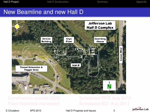
New Beamline and new Hall D
Thomas Jefferson National Accelerator Facility Page 4
IPR06 June 27-28, 2006
Thomas Jefferson National Accelerator Facility Page 4
Hall D Meeting May 13, 2009
Hall D Complex - Site Plan
N
Tunnel Extension &
Tagger Area
Construction started 2009Floor thickness increased
Scheduled RFE Aug 2010Scheduled BO Aug 2011
E.Chudakov APS 2010 Hall D Progress and Issues 5
Hall D Project Hall D Construction Summary Appendix
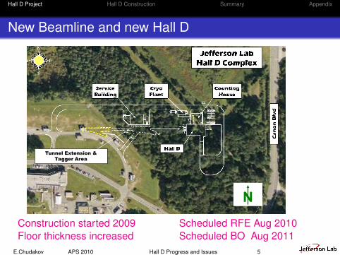
New Beamline and new Hall D
Thomas Jefferson National Accelerator Facility Page 4
IPR06 June 27-28, 2006
Thomas Jefferson National Accelerator Facility Page 4
Hall D Meeting May 13, 2009
Hall D Complex - Site Plan
N
Tunnel Extension &
Tagger Area
Construction started 2009Floor thickness increased
Scheduled RFE Aug 2010Scheduled BO Aug 2011
E.Chudakov APS 2010 Hall D Progress and Issues 5
Hall D Project Hall D Construction Summary Appendix
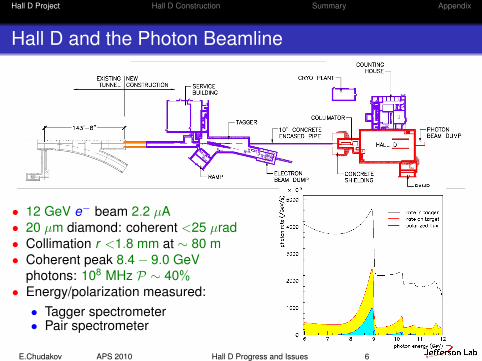
Hall D and the Photon Beamline
• 12 GeV e− beam 2.2 µA• 20 µm diamond: coherent <25 µrad• Collimation r <1.8 mm at ∼ 80 m• Coherent peak 8.4− 9.0 GeV
photons: 108 MHz P ∼ 40%• Energy/polarization measured:• Tagger spectrometer• Pair spectrometer
E.Chudakov APS 2010 Hall D Progress and Issues 6
Hall D Project Hall D Construction Summary Appendix
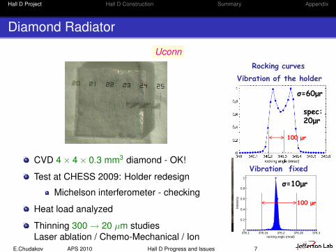
Diamond Radiator
Uconn
CVD 4× 4× 0.3 mm3 diamond - OK!
Test at CHESS 2009: Holder redesign
Michelson interferometer - checking
Heat load analyzed
Thinning 300 → 20 µm studiesLaser ablation / Chemo-Mechanical / Ion
Thomas Jefferson National Accelerator Facility Page 17
IPR September 22-24, 2009
Diamond Radiator
CVD 4x4x0.4 mm3 diamond - OK! Test at CHESS 2009: holder's vibration
• redesign the holder (no wires/more wires)• Michelson interferometer for checkingthe holder stability and diamond shape
Heat load is being analyzed (holder design) Diamond thinning by ablation:
• 248 nm excimer laser at UConn -not used for 10 years - testing needed
375.1 375.15 375.2 375.25 375.30
0.2
0.4
0.6
0.8
1
rocking angle (mrad)In
tensity
Rocking curves
Vibration fixed
σ=10μr
Interferometer Excimer laser
Vibration of the holder
σ=60μr
spec:20μr
Procurement of diamonds: FY11
100 μr
100 μr
E.Chudakov APS 2010 Hall D Progress and Issues 7
Hall D Project Hall D Construction Summary Appendix
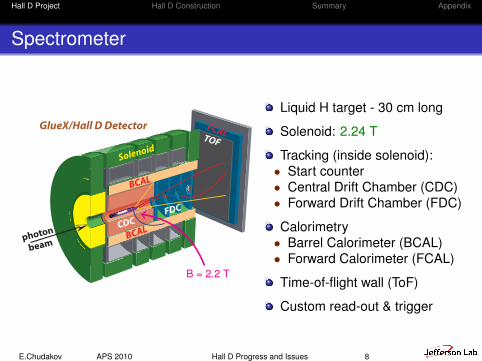
Spectrometer
Overview - Alex DzierbaHall D
Calorimeter Review1
Hall D/GlueX Calorimeter ReviewOverview and Physics Motivation
Alex R. DzierbaIndiana U and Jefferson Lab
1. Brief review of the physics: search for exotic hybrid mesons
2. Importance of neutral particle detection
3. Role of calorimetry and performance metrics
B = 2.2 T
Liquid H target - 30 cm long
Solenoid: 2.24 T
Tracking (inside solenoid):• Start counter• Central Drift Chamber (CDC)• Forward Drift Chamber (FDC)
Calorimetry• Barrel Calorimeter (BCAL)• Forward Calorimeter (FCAL)
Time-of-flight wall (ToF)
Custom read-out & trigger
E.Chudakov APS 2010 Hall D Progress and Issues 8
Hall D Project Hall D Construction Summary Appendix
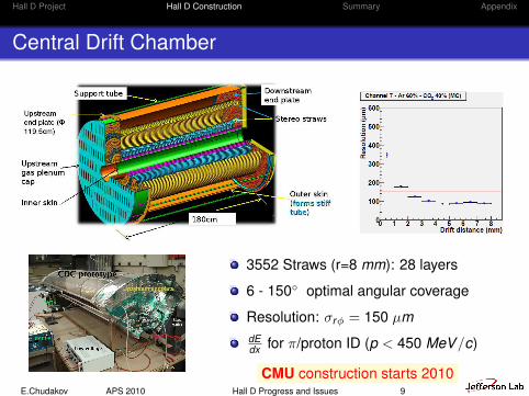
Central Drift Chamber
Thomas Jefferson National Accelerator Facility Page 28
IPR September 22-24, 2009
Central Drift Chambers
Stereo straws
Support tube
Outer skin
Upstream gas plenum
cap
Upstream
end plate (Φ
119.5cm)
Downstream end plate
Inner skin
180cm
dE/dx for p < 450 MeV/cGas mixture: ~60/40 Ar/CO2Angular Coverage: 6o-155o
Resolution:sr ~ 150 m, sz~1.5 mm
Developed at CMU, JLab
3552 Straws (r=8 mm): 28 layers
6 - 150 optimal angular coverage
Resolution: σrφ = 150 µmdEdx for π/proton ID (p < 450 MeV/c)
CMU construction starts 2010E.Chudakov APS 2010 Hall D Progress and Issues 9
Hall D Project Hall D Construction Summary Appendix
Central Drift Chamber - Progress
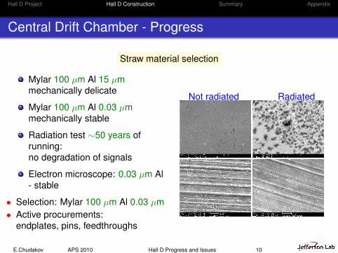
Straw material selection
Mylar 100 µm Al 15 µmmechanically delicate
Mylar 100 µm Al 0.03 µmmechanically stable
Radiation test ∼50 years ofrunning:no degradation of signals
Electron microscope: 0.03 µm Al- stable
• Selection: Mylar 100 µm Al 0.03 µm• Active procurements:
endplates, pins, feedthroughs
Not radiated Radiated
Figure 5: Comparison between a Lamina-thick straw that was not used (left) and the onethat was irradiated (right) at 5 and 20µm scale.
8
Figure 7: Comparison between a Lamina-thin straw that was not used (left) and the onethat was irradiated (right) at 5 and 20µm scale.
10
E.Chudakov APS 2010 Hall D Progress and Issues 10

Hall D Project Hall D Construction Summary Appendix
Forward Drift Chamber
JLab
4 packages × 6 planes (2300 wires, 10200 cathodestrips)
Plane: wire 0 and 2 cathode strip readouts ±75
→ suppression of ambiguities
1 - 30 angular coverage
σxy = 200 µmE.Chudakov APS 2010 Hall D Progress and Issues 11
Hall D Project Hall D Construction Summary Appendix
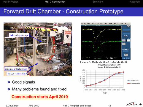
Forward Drift Chamber - Construction Prototype
Good signals
Many problems found and fixed
Construction starts April 2010
4
Figure 4: Cathode signals at +2200 V.
The peak amplitudes in figures 3 and 4 correspond to input impulse charges of 95 fC and 111 fC, respectively, which are within the linear region of the preamp. Limited streamer operation is clearly seen at +2200 V.
The output signal peak amplitudes for a sense wire and a cathode strip were measured as a function of the sense wire +HV with the Fe-55 source. The results are plotted in figure A3 in the appendix and show that the gains are matched between anode wires and cathode strips. Considering the ratio of the gains (3.2 mV/fC for cathode strips and 0.77 mV/fC for sense wires for the default preamp configuration) to be 4.2, the maximum slope region between +1950 V and +2050 V provides a reasonable operating range.
Direct observation of the gain matching between anode wires and cathode strips is made possible by requiring coincidences and proper placement of the Fe-55 source. Figure 5 shows cathode (top) and anode (bot)
pulses in coincidence at +2100 V for a long strip and a long anode wire.
Figure 5: Cathode (top) & Anode (bot).
As gain multiplication occurs close to the anode wire, the positive ion charge is halved between the cathode planes; the charge is then distributed among a few strips on each of the cathode planes. The peak cathode strip charge has been calculated to be about 1/5 of the anode wire charge and the preamp gains have been set accordingly. This is verified by observing similar pulse amplitudes for cathode strips and anode wires. Short and Long Wires and Strips
We observed similar signal characteristics across the detector for short and long anode wires and cathode strips. Figure 6 shows the anode (top) and cathode (bot) signals in coincidence for a short strip (close to the edge of the detector) and wire of half the length of the longest wire at +2000 V.
10 ns
7
Figure A3: Anode and cathode output peak amplitudes.
Figure A4: Anode and cathode input referred charge.
050
100150200250300350400
1800 1850 1900 1950 2000 2050 2100 2150 2200
Vp
(mV
)
+HV (V)
Output Peak Amplitude x HVAnode & Cathode with Fe‐55
Anode Fe‐55
Cathode Fe‐55
0
100
200
300
400
500
1800 1850 1900 1950 2000 2050 2100 2150 2200
Qin
(fC)
+HV (V)
Input Charge x HVAnode & Cathode with Fe‐55
Anode Fe‐55
Cathode Fe‐55
E.Chudakov APS 2010 Hall D Progress and Issues 12
Hall D Project Hall D Construction Summary Appendix
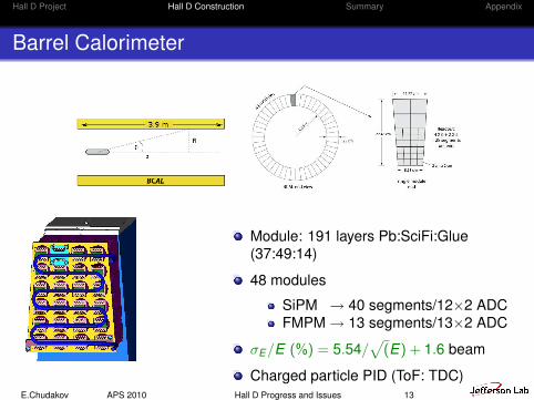
Barrel Calorimeter
Module: 191 layers Pb:SciFi:Glue(37:49:14)
48 modules
SiPM → 40 segments/12×2 ADCFMPM → 13 segments/13×2 ADC
σE/E (%) = 5.54/√
(E) + 1.6 beam
Charged particle PID (ToF: TDC)E.Chudakov APS 2010 Hall D Progress and Issues 13
Hall D Project Hall D Construction Summary Appendix
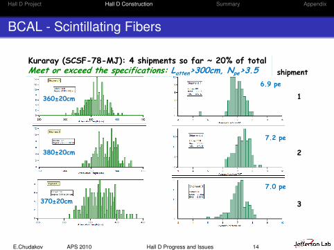
BCAL - Scintillating Fibers
Thomas Jefferson National Accelerator Facility Page 35
IPR September 22-24, 2009
BCAL: Scintillating Fibers QA
Kuraray (SCSF-78-MJ): 4 shipments so far ~ 20% of totalMeet or exceed the specifications: Latten>300cm, Npe>3.5
360±20cm
380±20cm
370±20cm
6.9 pe
7.2 pe
7.0 pe
shipment
1
2
3
E.Chudakov APS 2010 Hall D Progress and Issues 14
Hall D Project Hall D Construction Summary Appendix
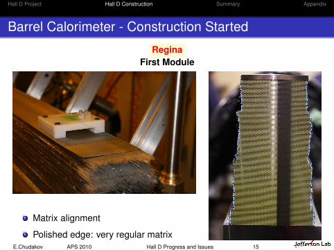
Barrel Calorimeter - Construction Started
ReginaFirst Module
Matrix alignment
Polished edge: very regular matrixE.Chudakov APS 2010 Hall D Progress and Issues 15
Hall D Project Hall D Construction Summary Appendix
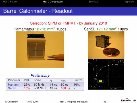
Barrel Calorimeter - Readout
Selection: SiPM or FMPMT - by January 2010Hamamatsu 12×12 mm2 10pcs
1
GlueX-doc-1387
Summary of the BCAL Readout Tests Using
SiPM Arrays
2 December 2009
Fernando J. Barbosa Jefferson Lab
1. Introduction
Electrical tests of the new Hamamatsu and SensL 4 x 4 SiPM arrays with the
prototype BCAL preamp have been performed. The objectives of these tests were to verify the correct electrical operation of the SiPMs as per the specifications supplied to the manufacturer. The BCAL readout parameters were previously described [1] and tests of the Hamamatsu and SensL 4 x 4 SiPM arrays have been presented [2], [3]. This note presents a summary of the most relevant parameters required for electrical qualification of the SiPM arrays delivered by Hamamatsu and SensL
2. The 4 x 4 SiPM Arrays
Figures 1 and 2 show the 4 x 4 SiPM arrays delivered by Hamamatsu and SensL, respectively. Ten (10) units were delivered by each of the vendors.
Figure 6: Front view of the preamp module. Figure 7: Side view.
PreliminaryProducer PDE noise τL τ10% unifrmHamam. 25% 60 MHz 14 ns 80 ns 10%SenSL 10% >60 MHz 13 ns 180 ns ?
SenSL 12×12 mm2 10pcs
1
GlueX-doc-1387
Summary of the BCAL Readout Tests Using
SiPM Arrays
2 December 2009
Fernando J. Barbosa Jefferson Lab
1. Introduction
Electrical tests of the new Hamamatsu and SensL 4 x 4 SiPM arrays with the
prototype BCAL preamp have been performed. The objectives of these tests were to verify the correct electrical operation of the SiPMs as per the specifications supplied to the manufacturer. The BCAL readout parameters were previously described [1] and tests of the Hamamatsu and SensL 4 x 4 SiPM arrays have been presented [2], [3]. This note presents a summary of the most relevant parameters required for electrical qualification of the SiPM arrays delivered by Hamamatsu and SensL
2. The 4 x 4 SiPM Arrays
Figures 1 and 2 show the 4 x 4 SiPM arrays delivered by Hamamatsu and SensL, respectively. Ten (10) units were delivered by each of the vendors.
Figure 6: Front view of the preamp module. Figure 7: Side view.
3
Figure 3: Single cell response with SensL readout.
Figure 4: 16 cell Sum output with SensL readout.
180 ns
196 ns
E.Chudakov APS 2010 Hall D Progress and Issues 16
Hall D Project Hall D Construction Summary Appendix
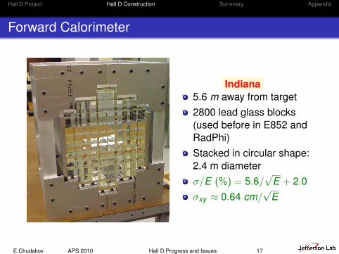
Forward Calorimeter
Indiana5.6 m away from target2800 lead glass blocks(used before in E852 andRadPhi)Stacked in circular shape:2.4 m diameterσ/E (%) = 5.6/
√E + 2.0
σxy ≈ 0.64 cm/√
E
E.Chudakov APS 2010 Hall D Progress and Issues 17
Hall D Project Hall D Construction Summary Appendix
Forward Calorimeter
Thomas Jefferson National Accelerator Facility Page 43
IPR September 22-24, 2009
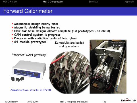
FCAL Progress (Indiana)
Mechanical design nearly final Magnetic shielding being tested New CW base design: almost complete (10 prototypes Jan 2010) CAN control system is progress Progress with radiation tests of lead glass 64-module prototype:
Ethernet-CAN gateway
Construction starts in FY10
E.Chudakov APS 2010 Hall D Progress and Issues 18

Hall D Project Hall D Construction Summary Appendix
Electronics
Progress:FADC-250 (16ch 12bit) - close to finalFADC-125 (72ch 12bit) - 1/2 done, Jun 2010 - finalCTP - doneTrigger checked with 2 crates: ∼ 200 kHz achieved
E.Chudakov APS 2010 Hall D Progress and Issues 19

Hall D Project Hall D Construction Summary Appendix
ASIC/GPC - Preamplifier/board for CDC and FDC
2
The three assembly variants will be nominally configured as follows: V1 – Input = Anode Readout
Gain = 0.6 mV/fC Outputs = Discriminators.
V2 – Input = Cathode Readout
Gain = 3 mV/fC Outputs = Analog.
V3 – Input = Anode Readout
Gain = 0.6 mV/fC Outputs = Analog.
Figures 1 and 2 show the top and bottom, respectively, of the preamp card and as received from assembly.
Figure 1: GPC-II – Top View.
Figure 2: GPC-II – Bottom View.
4. Test Setup A short-pulse charge injector, as depicted in figure 3, was used to test all the 24 preamp channels. The test setup is shown in appendix B.
Figure 3: Short –Pulse Charge Injector
Except as indicated, all the tests were performed with the ASIC bits set at their default values and with the outputs referenced to +1.25V through 56 Ω resistors. The standard GlueX output drive configuration is shown in appendix C, where RTERM differentially terminates the complementary outputs. Note that the cable specified for use with the CDC and the FDC has a characteristic impedance of 100 Ohm.
5. Linearity
The impulse response was measured for varying input charges. Figure 4 shows the response to 100 fC of charge for the low gain configuration with the following bit configuration: INPA1=INSH1=SH_RC=0, INPA2=INSH2=1
Input
51 Ω
910 Ω
1 pF
Temperature Sensor
GAS‐II ASIC
Output Connector
Input Connector
Input Protection
Power Section
To
Bit Resistors
8
Appendix D – Linearity Plots
y = 0.7727x + 1.8
y = 0.5683x + 1.1222
050
100150200250300350
0 100 200 300 400 500V
dout
(m
V)
Qin (fC)
Preamp Impulse Response (Vd x Qin)INPA1,INPA2, INSH1,INSH2,SH_RC,HIGAIN,EN_CMP=0101X00
Low Gain, RC=0
Low Gain, RC=1
fit1‐ 260fC@5%
fit2 ‐ 380fC@5%
y = 3.2394x + 10.933
y = 2.6048x + 4.13330
200
400
600
800
0 50 100 150 200 250
Vdo
ut (
mV
)
Qin (fC)
Preamp Impulse Response (Vd x Qin)INPA1,INPA2, INSH1,INSH2,SH_RC,HIGAIN,EN_CMP=0101X10
High Gain, RC=0
High Gain, RC=1
fit3 ‐ 110fC@5%
fit4 ‐ 130fC@5%
y = 0.8497x + 1.4667
y = 0.6233x + 1.15560
100
200
300
400
0 100 200 300 400 500
Vdo
ut (
mV
)
Qin (fC)
Preamp Impulse Response (Vd x Qin)INPA1,INPA2, INSH1,INSH2,SH_RC,HIGAIN,EN_CMP=0110X00
Low Gain, RC=0
Low Gain, RC=1
fit1‐ 260fC@5%
fit2 ‐ 320fC@5%
• Anodes: 1.2 mV/fC, Q<600 fC• Cathodes: 6.0 mV/fC, Q<120 fC• Anode discriminators: 3.2 fC
• ASIC-II (8ch) developed at Upenn
• GPC-II (3 ASICs) developed at JlabProduction summer 2010
E.Chudakov APS 2010 Hall D Progress and Issues 20
Hall D Project Hall D Construction Summary Appendix
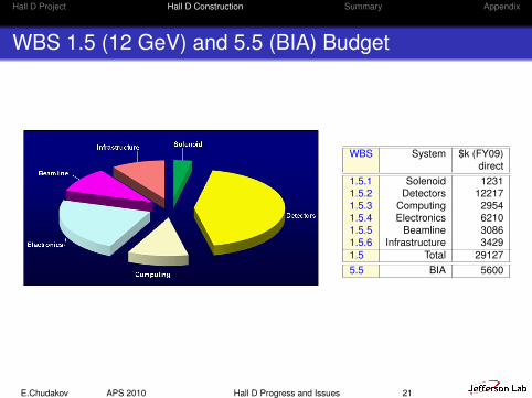
WBS 1.5 (12 GeV) and 5.5 (BIA) Budget
Thomas Jefferson National Accelerator Facility Page 3
IPR September 22-24, 2009
1.5 Cost Construction
WBS System FY09$k
Direct
1.5.1 Solenoid 1231
1.5.2 Detectors 12217
1.5.3 Computing 2954
1.5.4 Electronics 6210
1.5.5 Beamline 3086
1.5.6 Infrastructure 3429
1.5 Total 29127
Construction
16.0%
Remainder of 12GeV
Upgrade Total
Construction84.0%
Hall D Construction
Hall D construction: 16% of total
WBS System $k (FY09)direct
1.5.1 Solenoid 12311.5.2 Detectors 122171.5.3 Computing 29541.5.4 Electronics 62101.5.5 Beamline 30861.5.6 Infrastructure 34291.5 Total 291275.5 BIA 5600
E.Chudakov APS 2010 Hall D Progress and Issues 21
Hall D Project Hall D Construction Summary Appendix
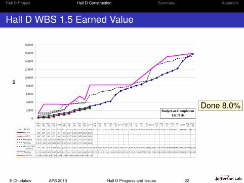
Hall D WBS 1.5 Earned Value
2/11/2010, 2:07 PM EVMSCharts: 1.5 Construction-Hall D 3 of 90
0
2,000
4,000
6,000
8,000
10,000
12,000
14,000
16,000
18,000
K$
Mar-
09
Apr-
09
May-
09
Jun-
09Jul-09
Aug-
09
Sep-
09
Oct-
09
Nov-
09
Dec-
09Jan-10
Feb-
10
Mar-
10
Apr-
10
May-
10
Jun-
10Jul-10
Aug-
10
Sep-
10
Oct-
10
Nov-
10
Dec-
10Jan-11
Feb-
11
Mar-
11
Apr-
11
May-
11
Jun-
11Jul-11
Aug-
11
Sep-
11
BCWS 272 468 591 839 1,120 1,317 1,528 2,054 2,378 2,529 2,948 3,225 3,477 3,913 4,166 5,796 6,720 7,157 7,594 8,029 8,300 9,023 9,427 9,923 10,65311,17511,63412,23114,06615,15615,779
BCWP 249 259 276 467 824 945 1,234 1,699 1,997 2,271 2,520
ACWP 206 247 284 473 844 929 1,237 1,681 2,050 2,401 2,681
Obligated 1,067 1,111 1,215 1,525 1,662 1,974 3,486 3,589 3,751 3,917 4,016
Pending 1,351 1,381 1,442 1,881 2,017 3,420 3,525 4,303 3,757 3,924 4,029
P6 Obl (FY10
Direct $)737 857 870 1,601 1,923 2,203 3,531 3,651 3,700 3,671 5,745 5,836 6,504 6,684 6,807 7,410 7,548 7,677 8,065 8,863 8,983 9,188 12,25013,13713,46713,87814,09614,67114,82315,06815,287
Funding 1,225 3,419 3,419 3,419 3,420 3,412 3,412 4,412 5,412 4,540 8,155 8,155 8,155 8,155 8,155 8,155 8,155 8,155 8,155 9,155 10,15511,15512,15513,15514,15515,15515,30515,45515,60515,75515,905
CAM EAC 31,26031,26031,26033,42233,42333,58433,58433,58433,58433,58434,530
12 GeV 1.5 Construction Hall D
Earned Value $K
Budget-at-Completion
$31,711K
Done 8.0%
E.Chudakov APS 2010 Hall D Progress and Issues 22
Hall D Project Hall D Construction Summary Appendix
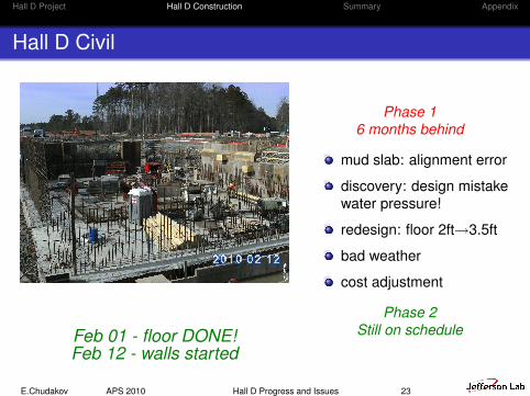
Hall D Civil
Feb 01 - floor DONE!Feb 12 - walls started
Phase 16 months behind
mud slab: alignment error
discovery: design mistakewater pressure!
redesign: floor 2ft→3.5ft
bad weather
cost adjustment
Phase 2Still on schedule
E.Chudakov APS 2010 Hall D Progress and Issues 23
Hall D Project Hall D Construction Summary Appendix
The Gluex collaboration
Carnegie Mellon (CDC)
Catholic University
Christopher Newport
Florida International(start-counter)
Florida State (ToF wall)
Glasgow (γ-beam)
Indiana University (FCal)
IUCF (CDC, FDC)
University on NC, A&T
University on NC,Wilmington
Jefferson Lab (CDC, FDC,BCal,γ-beam)
University of Connecticut(γ-beam)
University of Athens (BCal)
University of Pennsylvania(CDC, FDC)
University of Regina (BCal)
Yerevan (γ-beam)
E.Chudakov APS 2010 Hall D Progress and Issues 24
Hall D Project Hall D Construction Summary Appendix
Summary
PED finishedConstruction started: BCAL,FCAL,FDC,CDCreasonably good progress, about 1-2 months behindNew collaborators: NC A&T, WilmingtonNew hires: Hall Leader, Work Coordinator, 2 scientists,1 engineer, 2 techsIssues:
Manpower (slowly improving)Solenoid - takes much more resources than anticipatedLehman review Sept 2009: concernTechnical review Nov 2009: endorsed the current planCoil testing - till July 2011
E.Chudakov APS 2010 Hall D Progress and Issues 25
Hall D Project Hall D Construction Summary Appendix
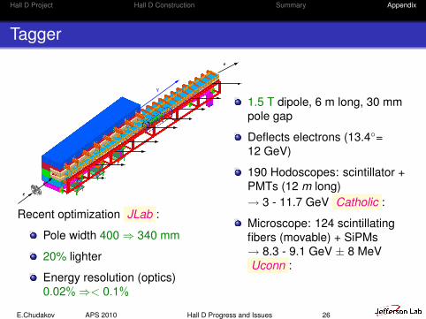
Tagger
e
e
γ
Recent optimization JLab :
Pole width 400 ⇒ 340 mm
20% lighter
Energy resolution (optics)0.02%⇒< 0.1%
1.5 T dipole, 6 m long, 30 mmpole gap
Deflects electrons (13.4=12 GeV)
190 Hodoscopes: scintillator +PMTs (12 m long)→ 3 - 11.7 GeV Catholic :
Microscope: 124 scintillatingfibers (movable) + SiPMs→ 8.3 - 9.1 GeV ± 8 MeVUconn :
E.Chudakov APS 2010 Hall D Progress and Issues 26
Hall D Project Hall D Construction Summary Appendix
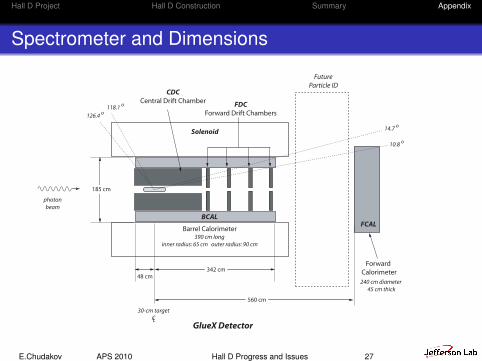
Spectrometer and Dimensions
560 cm
342 cm
48 cm
185 cm
BCAL
CDC
Central Drift ChamberFDC
Forward Drift Chambers
GlueX Detector
Forward
Calorimeter
Solenoid
390 cm long
inner radius: 65 cm outer radius: 90 cm
240 cm diameter
45 cm thick
30-cm target
CL
Future
Particle ID
photon
beam
10.8 o
14.7 o
118.1 o
126.4 o
FCAL Barrel Calorimeter
E.Chudakov APS 2010 Hall D Progress and Issues 27
Hall D Project Hall D Construction Summary Appendix
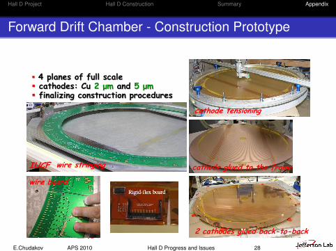
Forward Drift Chamber - Construction Prototype
Thomas Jefferson National Accelerator Facility Page 27
IPR September 22-24, 2009
FDC progress: construction prototype
4 planes of full scale cathodes: Cu 2 μm and 5 μm finalizing construction procedures
IUCF wire stringing
wire board
cathode tensioning
cathode glued to the frame
2 cathodes glued back-to-back
E.Chudakov APS 2010 Hall D Progress and Issues 28
Hall D Project Hall D Construction Summary Appendix
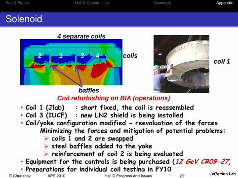
Solenoid
Thomas Jefferson National Accelerator Facility Page 22
IPR September 22-24, 2009
Solenoid
• Coil 1 (Jlab) : short fixed, the coil is reassembled• Coil 3 (IUCF) : new LN2 shield is being installed• Coil/yoke configuration modified - reevaluation of the forces
Minimizing the forces and mitigation of potential problems: coils 1 and 2 are swapped steel baffles added to the yoke reinforcement of coil 2 is being evaluated
• Equipment for the controls is being purchased (12 GeV CR09-27)• Preparations for individual coil testing in FY10
coils
baffles
coil 1
4 separate coils
Coil refurbishing on BIA (operations)
2 1 3 4
E.Chudakov APS 2010 Hall D Progress and Issues 29