Embed Size (px)
Citation preview

Hall D Cryostat Heat load and Flow calculations
• What are we doing ?1. Measuring the heat leak into the magnet for all the 4 coils 2. Determining of number of super insulation layers to reduce radiation3. Determining the equivalent diameter for the panels and the plumbing4. Evaluating the head loss in the plumbing due to friction5. Also considered the effects of two phase flow in the panel
6. Mass flow rate of LN2 in the heat shields
• Why are we doing ?1. To determine the relation between flow rate and heat input2. To address whether the coolant pipes are large enough to carry
away the heat leakage with out excessive temperature rise in the heat shields
Ravi AnumagallaJefferson LabGlueX collaboration meetingMay 20th

Cake Pan
Vacuum Tank Cover
Helium Vessel
Inner Panel
Outer Panel
Intermediate Panel
Support & Side Panels
73 Dia
77.5 Dia
114 Dia
Cross section of coil 2,3,4 All Dimension Are In Inches
Support Link

Heat leak into
coils
Conduction70%
Radiation30%
AtmosphereSupportLinks
Convection ? Is reduced by evacuating the coil to 10 -5 torr
The total heat load on each coils are as follows
22736Coil4
9412Coil2/coil3
Total heat load
(Watts)
# of Support links
Coil

Hall D thermo-siphon

Determination of equivalent Diameter
• Verification of Equivalent diameter:– Methods
• Analytical calculations
• CAD geometry verification
• Experimental calculations
• Governing Equations for Analytical Calculations– These Equations have been derived from Darcy Weibach’s equation and Blasius
Equations
75.4/175.475.4
25.0
2
2
5
5
NdD
d
Q
Q
D
f
f
f
f
Q
Q
d
D
sl
s
s
l
l
s
l
s
l
s
l
l
l Where
Dl = Equivalent diameter for N number of passages
ds= Equivalent diameter for a single passage
N = number of passages
f = friction factor in a single passage
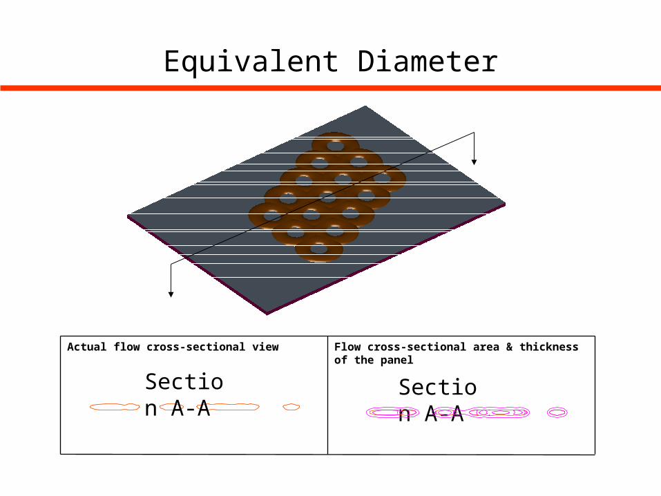
Equivalent Diameter
Section A-A
Section A-A
Flow cross-sectional area & thickness of the panelActual flow cross-sectional view
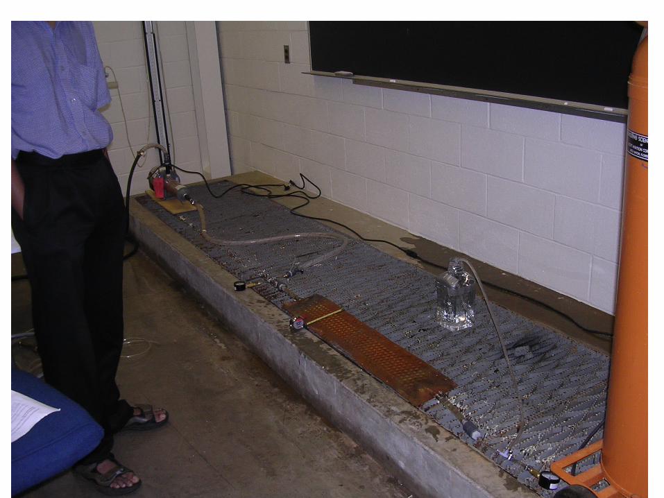
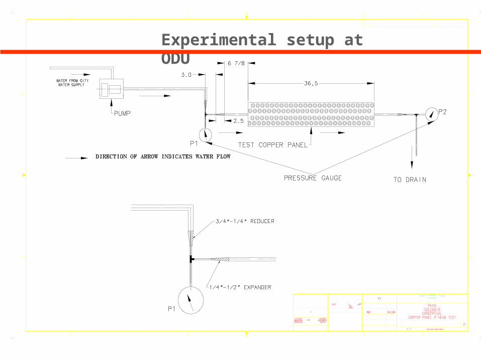
Experimental setup at ODU
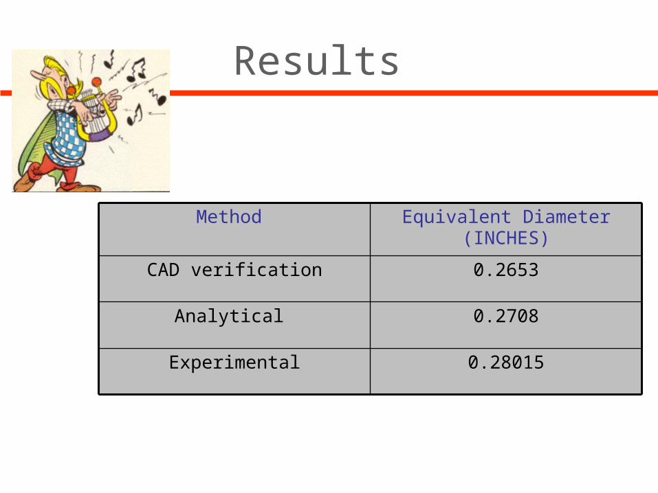
Results
Equivalent Diameter (INCHES)Method
0.28015Experimental
0.2708Analytical
0.2653CAD verification

Flow Calculations
• Calculations are based on homogenous model
• The governing equations are
DPliqDPmixxDPcorrDPtot )()(
totgrav
xliqgrav
DPDP
ghDP )(
DPtot = Total pressure drop (gm/cm2)
DPcorr = Two phase pressure drop correction factor
DPmix = Pressure drop in two-phase flow piping (Panels/Returns) (gm/cm2)
DPliq = Pressure drop in single phase supply line (gm/cm2)
DPgrav = Differential density induced driving pressure (gm/cm2)

Hall-D LN2 thermo-Siphon Flowrate
0
20
40
60
80
100
120
140
160
0 200 400 600 800
Heat Load(W)
Ma
ss
flo
w r
ate
(g
m/s
ec
)
MflowrateC
OIL
2 /
CO
IL 3
CO
IL 4
94 227
Mass Flow Rate VS Heat Load
The cooling is generally considered to adequate if the thermo-siphon flow rate increases under an increased heat load, the safe design load to choose would generally be 6 times or more
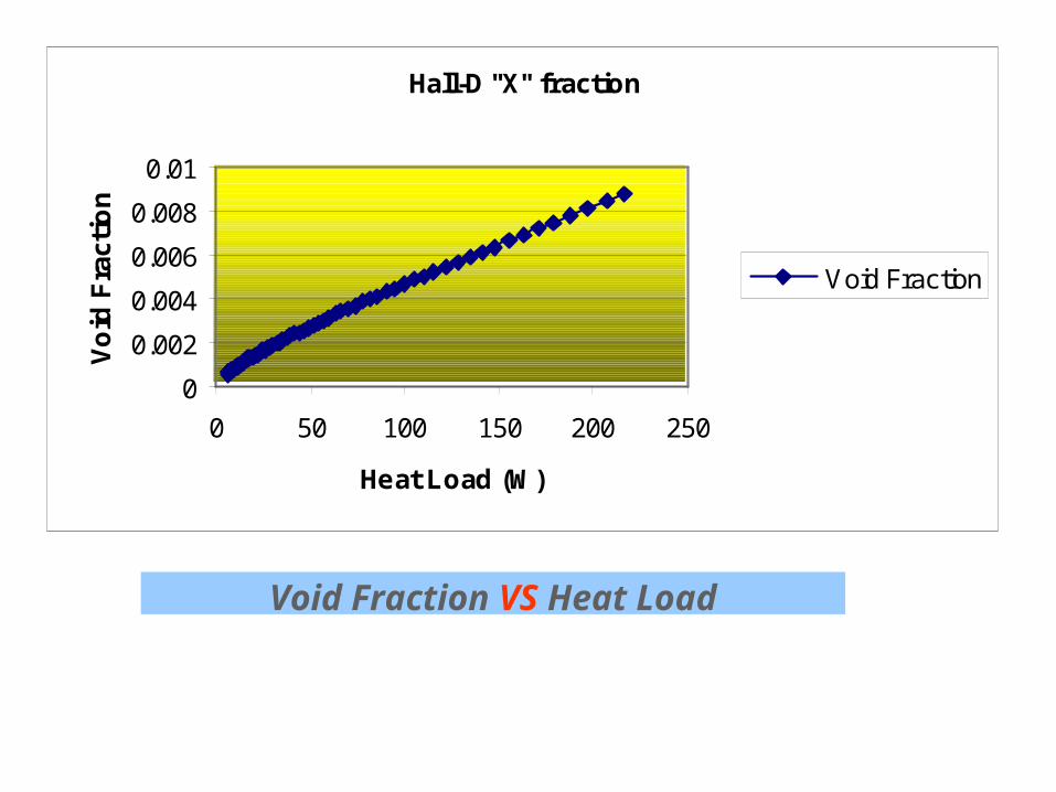
Hall-D "X" fraction
0
0.002
0.004
0.006
0.008
0.01
0 50 100 150 200 250
Heat Load (W)
Vo
id F
ract
ion
Void Fraction
Void Fraction VS Heat Load


![Cased and Uncased Heat Pump / Cooling Coils 1 1/2 - 5 Ton ...€¦ · UPFLOW / DOWNFLOW CASED COILS * Reducer supplied with R-410A model [1] These indoor coils are A.R.I. certified](https://img.pdfslide.us/doc/110x75/60194eaf12611006807b6a53/cased-and-uncased-heat-pump-cooling-coils-1-12-5-ton-upflow-downflow.jpg)