Embed Size (px)
Citation preview
HALFEN PRECAST PANEL ANCHORS
FACADE
3
CONTENTS
Product selector 4Standard Types 4Variations 4
Identification of panel support fixings 5
Using Anchor bolts for panel support fixings 5
Calculation of wall panel loadings 6
Halfen panel support fixings 8Halfen panel support fixings Type FPA-3 8Halfen-panel support fixing type FPA-5 10Halfen panel support fixing type FPA-5Z 12Halfen panel support fixing type FPA-5A 13Halfen panel support fixing type FPA-5AZ 14Halfen panel support fixing type FPA-S/-S1 15Assembly and installation of FPA-3 16Assembly and installation of FPA-5 17Perforated Hanger strap for Type FPA 3 18Perforated Hanger strap for Type FPA 5 18
Halfen top fixing dowel Type WPA-A/B 19Assembly and installation 21
Horizontal Anchoring 22Halfen Spacer bolts type DS-13/16/25 23HALFEN Restraint tie type HKZ 26HALFEN Restraint tie type HKZ-GF 26HALFEN Restraint tie type HKZ-GU 27HALFEN Restraint with turnbuckle type SPV 28HALFEN Adjustable restraint type LD 28Plastic Wind Anchors type WDK 29
HALFEN Dowel restraint fixings 31Upper parts and Dowels 31Lower parts 32Spiral reinforcement Type HFV-B fits HFV1, HFV5 and HFV9 32Possible combinations of dowel restraint fixings 32Adjustment fixing with Reinforcement 33Adjustment fixing type HFV-6N 33
HALFEN Parapet corbel 34HALFEN Parapet corbel BRA-N/A 36HALFEN Parapet corbel BRA-NJ/AJ 37
Assembly accessories for Halfen panel support fixing 40
Tender texts 41
Enquiry / Order form 42
1TC
C03
0010
STANDARD TYPES
4
PRODUCT SELECTOR
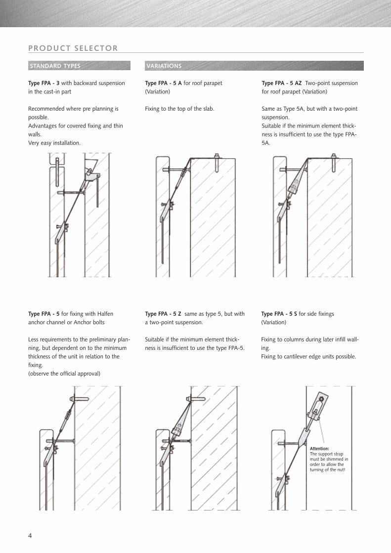
Type FPA - 3 with backward suspensionin the cast-in part
Recommended where pre planning ispossible.Advantages for covered fixing and thinwalls.Very easy installation.
Type FPA - 5 A for roof parapet (Variation)
Fixing to the top of the slab.
Type FPA - 5 for fixing with Halfenanchor channel or Anchor bolts
Less requirements to the preliminary plan-ning, but dependent on to the minimumthickness of the unit in relation to thefixing.(observe the official approval)
Type FPA - 5 Z same as type 5, but witha two-point suspension.
Suitable if the minimum element thick-ness is insufficient to use the type FPA-5.
Type FPA - 5 AZ Two-point suspensionfor roof parapet (Variation)
Same as Type 5A, but with a two-pointsuspension.Suitable if the minimum element thick-ness is insufficient to use the type FPA-5A.
Type FPA - 5 S for side fixings(Variation)
Fixing to columns during later infill wall-ing.Fixing to cantilever edge units possible.
VARIATIONS
Attention:The support strapmust be shimmed inorder to allow theturning of the nut!
5
PRODUCT SELECTOR
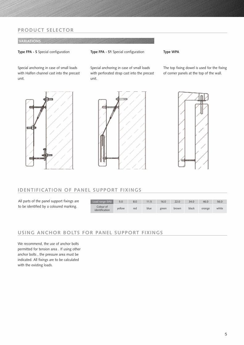
Type FPA - S1 Special configuration
Special anchoring in case of small loadswith perforated strap cast into the precastunit.
Type FPA - S Special configuration
Special anchoring in case of small loadswith Halfen channel cast into the precastunit.
Type WPA
The top fixing dowel is used for the fixingof corner panels at the top of the wall.
VARIATIONS
IDENTIFICATION OF PANEL SUPPORT FIXINGS
All parts of the panel support fixings areto be identified by a coloured marking.
Load range (kN)
Colour of identification
5.0 8.0 11.5 16.0 22.0 34.0 46.0 56.0
whiteyellow red blue green brown black orange
USING ANCHOR BOLTS FOR PANEL SUPPORT FIXINGS
We recommend, the use of anchor boltspermitted for tension area . If using otheranchor bolts , the pressure area must beindicated. All fixings are to be calculatedwith the existing loads.
6
CALCULATION OF WALL PANEL LOADINGS
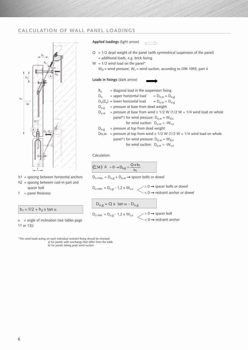
Applied loadings (light arrow)
Q = 1/2 dead weight of the panel (with symmetrical suspension of the panel) + additional loads, e.g. brick facing
W = 1/2 wind load on the panel* Wd = wind pressure, Ws = wind suction, according to DIN 1055, part 4
Loads in fixings (dark arrow)
Rz = diagonal load in the suspension fixingDo = upper horizontal load = Do,w + Do,g
Du(Zu) = lower horizontal load = Du,w + Du,g
Du,g = pressure at base from dead weight Du,w = pressure at base from wind ≅ 1/2 W (1/2 W = 1/4 wind load on whole
panel*) for wind pressure: Du,w = Wd,u
for wind suction: Du,w = -Ws,u
Do,g = pressure at top from dead weightDo,w = pressure at top from wind ≅ 1/2 W (1/2 W = 1/4 wind load on whole
panel*) for wind pressure: Do,w = Wd,o
for wind suction: Do,w = -Ws,o
Calculation:
Du max. = Du,g + Du,w spacer bolts or dowel
Du min. = Du,g - 1,2 x Ws,u
Do min. = Do,g - 1,2 x Ws,o
( )1
1g,u
hbxQ
D0 =→=Μ∑
≥ 0 spacer bolts or dowel
< 0 restraint anchor or dowel
≥ 0 spacer bolt
< 0 restraint anchor
*The wind loads acting on each individual restraint fixing should be checked: a) for panels with overhangs that differ from the tableb) for panels taking peak wind suction
h1 = spacing between horizontal anchorsh2 = spacing between cast-in part and
spacer boltf = panel thickness
α = angle of inclination (see tables page11 or 13))
b1
h1
W
Q
Du (Zu)
f
B
h2A
Do
Rz
α
A
b1 = f/2 + h2 x tan αDo,g = Q x tan α - Du,g
7
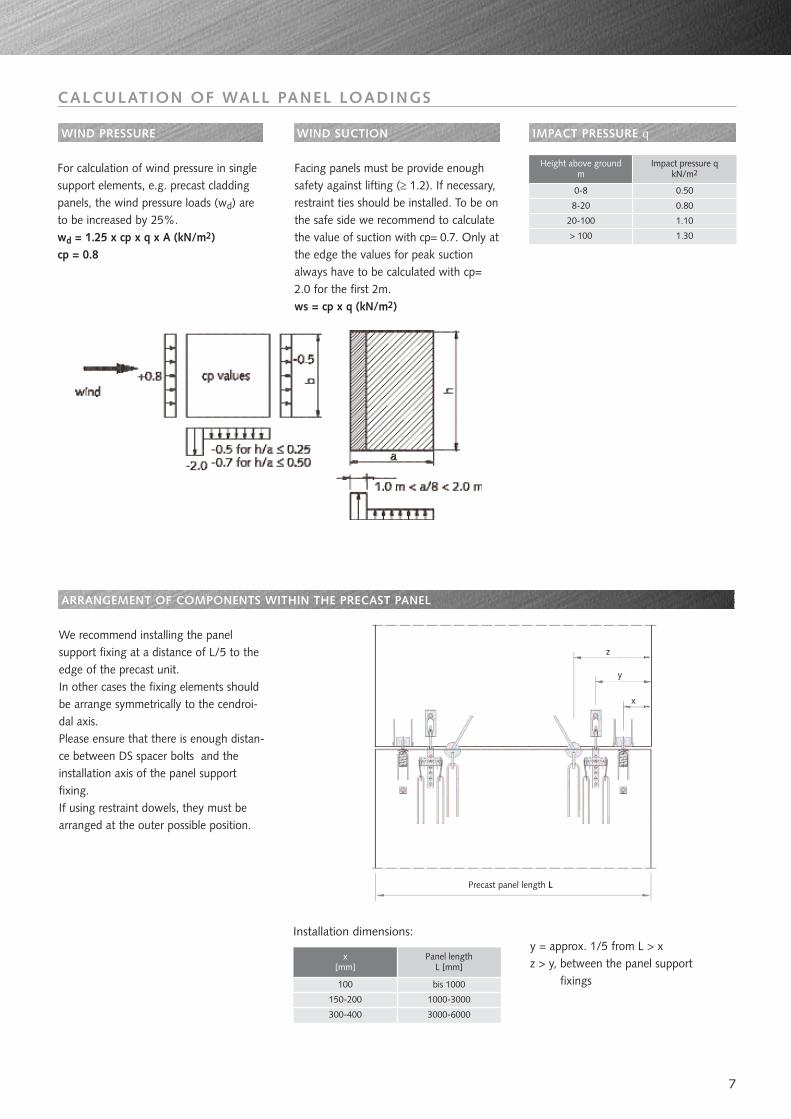
WIND PRESSURE WIND SUCTION
For calculation of wind pressure in singlesupport elements, e.g. precast claddingpanels, the wind pressure loads (wd) areto be increased by 25%.wd = 1.25 x cp x q x A (kN/m2)cp = 0.8
Facing panels must be provide enoughsafety against lifting (≥ 1.2). If necessary,restraint ties should be installed. To be onthe safe side we recommend to calculatethe value of suction with cp= 0.7. Only atthe edge the values for peak suctionalways have to be calculated with cp=2.0 for the first 2m.ws = cp x q (kN/m2)
Height above groundm
0-8
Impact pressure qkN/m2
8-20
20-100
> 100
0.50
0.80
1.10
1.30
ARRANGEMENT OF COMPONENTS WITHIN THE PRECAST PANEL
IMPACT PRESSURE q
We recommend installing the panelsupport fixing at a distance of L/5 to theedge of the precast unit.In other cases the fixing elements shouldbe arrange symmetrically to the cendroi-dal axis.Please ensure that there is enough distan-ce between DS spacer bolts and theinstallation axis of the panel supportfixing. If using restraint dowels, they must bearranged at the outer possible position.
x [mm]
Panel lengthL [mm]
100
150-200
300-400
bis 1000
1000-3000
3000-6000
Installation dimensions:y = approx. 1/5 from L > xz > y, between the panel support
fixings
z
y
x
Precast panel length L
CALCULATION OF WALL PANEL LOADINGS
8
HALFEN PANEL SUPPORT FIXINGS TYPE FPA-3Independently approved, installation details and selection table
8.0
11.5
16.0
22.0
34.0
46.0
56.0
70
70
125 150 180 230 36 33 85 173 12 52 600
Load range
kN
5.0
Lower cast-in element FPA-3-E
fmin
brmin
crmin c e (f1-e)
80
80
90
100
115
50
60
(m+n) w dia. x y z
80
100
110
140
107
112
12270
132
132
160
180
120
130
140
160
160
200
220
8
13
18
19
19
25
29 33
23
27
20
18
15
14 51
53
60
68
71
75
80
107
116
133
148
151
164
166
6
6
8
8
8
10
12
-
-
-
-
-
25
42
250
250
250
350
400
500
500
8.0
11.5
16.0
22.0
34.0
46.0
56.0 213 16 400 200 58 120 255 94
Load range
kN
5.0
a dia. i g armin s p to ro
Cast-in support FPA-3-R
81 6 200 70 24 60 121 38
85 6 200 80 24 60 130 40
96 8 200 90 33 80 150 45
115 8 250 120 35 80 165 50
134 10 250 130 36 100 179 60
155 12 300 150 44 100 202 70
190 16 350 170 53 120 236 80
Order-no.0240.250-
00001
00002
00003
00004
00005
00006
00007
00008
subject to change without noticeall dimensions in mm
8.0
11.5
16.0
22.0
34.0
46.0
56.000015
Load range
kN
5.0
Order-no.0240.080-
Complete set FPA-3-G-
00001
00003
00005
00007
00009
00011
00013
Cavity
40-120
130-220
40-120
130-220
130-220
40-120
00002
00004
00006
40-120
130-200
40-130
140-240
40-120
130-210
50-120
130-220
60-120
130-230 00016
00014
00012
00010
00008
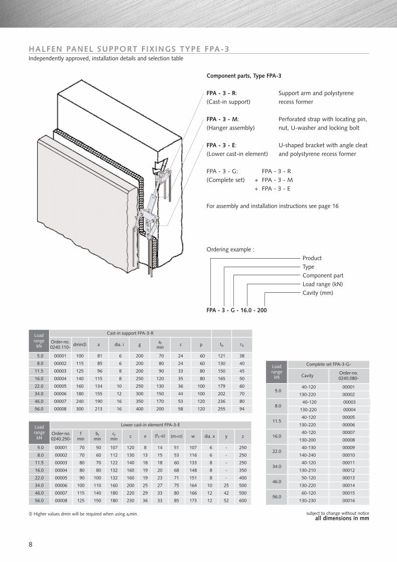
Component parts, Type FPA-3
FPA - 3 - R: Support arm and polystyrene(Cast-in support) recess former
FPA - 3 - M: Perforated strap with locating pin, (Hanger assembly) nut, U-washer and locking bolt
FPA - 3 - E: U-shaped bracket with angle cleat (Lower cast-in element) and polystyrene recess former
FPA - 3 - G: FPA - 3 - R(Complete set) + FPA - 3 - M
+ FPA - 3 - E
For assembly and installation instructions see page 16
Ordering example :ProductTypeComponent partLoad range (kN)Cavity (mm)
FPA - 3 - G - 16.0 - 200
Order-no.0240.110-
00001
00002
00003
00004
00005
00006
00007
00008
dmin
100
115
125
140
160
180
240
300
Higher values dmin will be required when using armin.
9
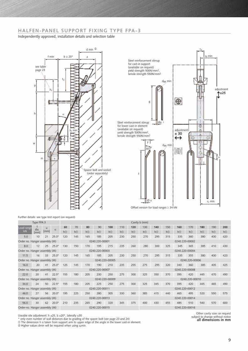
HALFEN-PANEL SUPPORT FIXING TYPE FPA-3Independently approved, installation details and selection table
Useable site adjustment: h ±25, b ±20*, laterally ±30* only even number of wall distances due to grading of the spacer bolt (see page 23 and 24)
The dimension h is taken from support arm to upper edge of the angle in the lower cast-in element.Higher values dmin will be required when using armin.
Other cavity sizes on requestsubject to change without notice
all dimensions in mm
Steel reinforcement stirrupfor cast-in support (available on request)yield strength 500N/mm2,tensile strength 550N/mm2
Steel reinforcement stirrupfor lower cast-in element(available on request) yield strength 500N/mm2,tensile strength 550N/mm2
Spacer bolt and socket(order separately)
ro
ar min
c
t
cr minØ x
Offset version for load ranges ≥ 34 kN
Further details: see type test report (on request)
z
y
g
dia. i
30°dBR min
dBR min
u
w
h
p
f min
d min
b ± 20* a
to
hr
α
e
m n
br min
f1
see tablepage 23
adjustment±25
adjustment± 30
8.0
11.5
16.0
22.0
34.0
46.0
56.0 30 62 20.0° 210 235 265 290 320 345 375 400 430 455 485 510 540 570 600
5.0
tdia.
[mm]
u[mm] α
h h
10
12
h h h h h h h h h h h h h
21 25.0° 120 145 165 185 205 230 250 270 295 315 335 360 380 400 420
25 25.0° 130 150 170 195 215 235 260 280 300 325 345 365 385 410 430
16 33 25.0° 120 145 165 185 205 230 250 270 295 315 335 355 380 400 420
20 41 25.0° 125 145 170 190 210 235 255 275 295 320 340 360 385 405 425
20 41 22.5° 155 180 205 230 250 275 300 325 350 370 395 420 445 470 490
24 50 22.5° 155 180 205 225 250 275 300 325 345 370 395 420 445 465 490
27 56 20.0° 195 225 250 280 305 330 360 385 415 440 465 495 520 550 575
Load rangekN
60 70 80 100 110 12090 130 140 150 170 200190180160
Type FPA 3 Cavity b (mm)
0240.220-00001
0240.220-00003
Order no. Hanger assembly (M)
Order no. Hanger assembly (M)
Order no. Hanger assembly (M)
Order no. Hanger assembly (M)
Order no. Hanger assembly (M)
Order no. Hanger assembly (M)
Order no. Hanger assembly (M)
Order-no. Hanger assembly (M)
0240.220-00002
0240.220-00005
0240.220-00007
0240.220-00009
0240.220-00011
0240.220-00013
0240.220-00015
0240.220-00004
0240.220-00008
0240.220-00010
0240.220-00012
0240.220-00014
0240.220-00016
0240.220-00006
Load range[kN]
Order no.
0240.030-
5.0
0000160-100110-180 00002190-280 00003C
ompl
ete
set
FPA
-5-G
-
8.0 11.5 16.0 22.0 34.0 46.0 56.0
60-110120-180190-260
000040000500006
000070000800009
000100001100012
000130001400015
Order no.
0240.030-
Order no.
0240.030-
Order no.
0240.030-
Order no.
0240.030-
Order no.
0240.030-
Order no.
0240.030-Order no.
000160001700018
000190002000021
000220002300024
60-120130-190200-290
60-140150-190200-280
60-140150-200210-320
70-160170-220230-310
90-160170-230240-310
100-150160-250260-350
Cavity Cavity Cavity Cavity Cavity Cavity Cavity
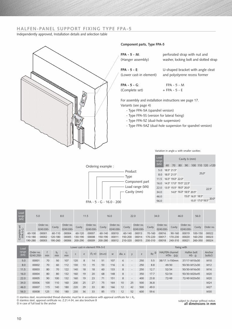
Ordering example :ProductTypeComponent partLoad range (kN)Cavity (mm)
FPA - 5 - G - 16.0 - 200
10
subject to change without notice. all dimensions in mm
Loadrange[kN]
Cavity b (mm)
60 70 80 90 100 110 120 >120
5.0
8.0
11.5
16.0
22.0
34.0
46.0
56.0
18.5°
18.5°
16.5°
14.5°
13.5°
21.5°
21.5°
19.0°
17.0°
15.5°
14.0°
22.0°
19.5°
18.0°
16.0°
22.5°
20.0°
18.5°
15.0°
20.5°
16.5°
15.5°
18.5°
17.0°
22.5°
20.0°18.5°
25,0°
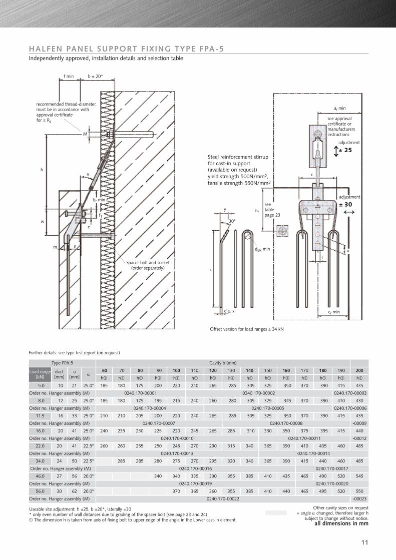
HALFEN-PANEL SUPPORT FIXING TYPE FPA-5Independently approved, Installation details and selection table
Component parts, Type FPA-5
FPA - 5 - M: perforated strap with nut and (Hanger assembly) washer, locking bolt and slotted strap
FPA - 5 - E: U-shaped bracket with angle cleat (Lower cast-in element) and polystyrene recess former
FPA - 5 - G: FPA - 5 - M(Complete set) + FPA - 5 - E
For assembly and installation instructions see page 17.Variants (see page 4)
- Type FPA-5A (spandrel version)- Type FPA-5S (version for lateral fixing)- Type FPA-5Z (dual-hole suspension)- Type FPA-5AZ (dual-hole suspension for spandrel version)
8.0
11.5
16.0
22.0
34.0
46.0
56.0
70
70
125 150 180 230 36 33 85 173 12 52 600
Loadrange[kN]
5.0
Lower cast-in element FPA-5-E
fmin
brmin
crmin c e (f1-e)
80
80
90
100
115
50
60
(m+n) w dia. x y z
107 120 8 14 51 107 6 - 250
112 130 13 15 53 116 6 - 250
70 122 140 18 18 60 133 8 - 250
80 132 160 19 20 68 148 8 - 350
100 132 160 19 23 71 151 8 - 400
110 160 200 25 27 75 164 10 25 500
140 180 220 29 33 80 166 12 42 500
Order no.0240.250-
00001
00002
00003
00004
00005
00006
00007
00008
fixing with
Rz Anchorbolts
HALFEN channelHTA-
38/17. l=150mm5.5
8.8
12.7
17.7
23.8
36.8
49.0
59.6
49/30
52/34
52/34
37/17-M10x30
50/30-M12x30
50/30-M16x30
50/30-M20x45
M10
M12
M16
M20
M20
M24
M27
M30
Halfen boltHS-
Variation in angle α with smaller cavities:
stainless steel, recommended thread-diameter, must be in accordance with approval certificate for ≥ Rzstainless steel, approval certificate no. Z.21.4-34, see also brochure Bin case of full load to the anchor
72/49 72/49 M20x50
Cavity
11
8.0
11.5
16.0
22.0
34.0
46.0
56.0 30 62 20.0° 370 365 360 355 385 410 440 465 495 520 550
5.0
dia.t[mm]
u[mm] α
h h
10
12
h h h h h h h h h h h h h
21 25.0° 185 180 175 200 220 240 265 285 305 325 350 370 390 415 435
25 25.0° 185 180 175 195 215 240 260 280 305 325 345 370 390 410 430
16 33 25.0° 210 210 205 200 220 240 265 285 305 325 350 370 390 415 435
20 41 25.0° 240 235 230 225 220 245 265 285 310 330 350 375 395 415 440
20 41 22.5° 260 260 255 250 245 270 290 315 340 365 390 410 435 460 485
24 50 22.5° 285 285 280 275 270 295 320 340 365 390 415 440 460 485
27 56 20.0° 340 340 335 330 355 385 410 435 465 490 520 545
Load range[kN]
60 70 80 100 110 12090 130 140 150 170 200190180160
Type FPA 5 Cavity b (mm)
0240.170-00001
0240.170-00004
Order no. Hanger assembly (M)
Order no. Hanger assembly (M)
Order no. Hanger assembly (M)
Order no. Hanger assembly (M)
Order no. Hanger assembly (M)
Order no. Hanger assembly (M)
Order no. Hanger assembly (M)
0240.170-00007
0240.170-00010
0240.170-00013
0240.170-00019
0240.170-00022
HALFEN PANEL SUPPORT FIXING TYPE FPA-5Independently approved, installation details and selection table
Steel reinforcement stirrupfor cast-in support (available on request) yield strength 500N/mm2,tensile strength 550N/mm2
see approval certificate ormanufacturersinstructions
Spacer bolt and socket(order separately)
ar min
c
cr mindia. x
Offset version for load ranges ≥ 34 kN
Further details: see type test report (on request)
z
hr
seetablepage 23
w
h
M
f min
α
e
m n
recommended thread-diameter,must be in accordance withapproval certificate for ≥ Rz
b ± 20*
t
y
30°
dBR min u
f1
br min
Order no. Hanger assembly (M) 0240.170-00016
-00009
0240.170-00003
0240.170-00006
-00012
Useable site adjustment: h ±25, b ±20*, laterally ±30* only even number of wall distances due to grading of the spacer bolt (see page 23 and 24)
The dimension h is taken from axis of fixing bolt to upper edge of the angle in the Lower cast-in element.
Other cavity sizes on request= angle α changed, therefore larger h
subject to change without notice. all dimensions in mm
adjustment
± 25
adjustment
± 30
0240.170-00002
0240.170-00005
0240.170-00008
0240.170-00011
0240.170-00014
0240.170-00017
0240.170-00020
-00023
12
Loadrange[kN]
Cavity b (mm)
60 70 80 90 100 110 120 >120
5.0
8.0
11.5
16.0
22.0
34.0
46.0
56.0
18.5°
18.5°
16.5°
14.5°
13.5°
21.5°
21.5°
19.0°
17.0°
15.5°
14.0°
22.0°
19.5°
18.0°
16.0°
22.5°
20.0°
18.5°
15.0°
20.5°
16.5°
15.5°
18.5°
17.0°
22.5°
20.0°18.5°
25,0°
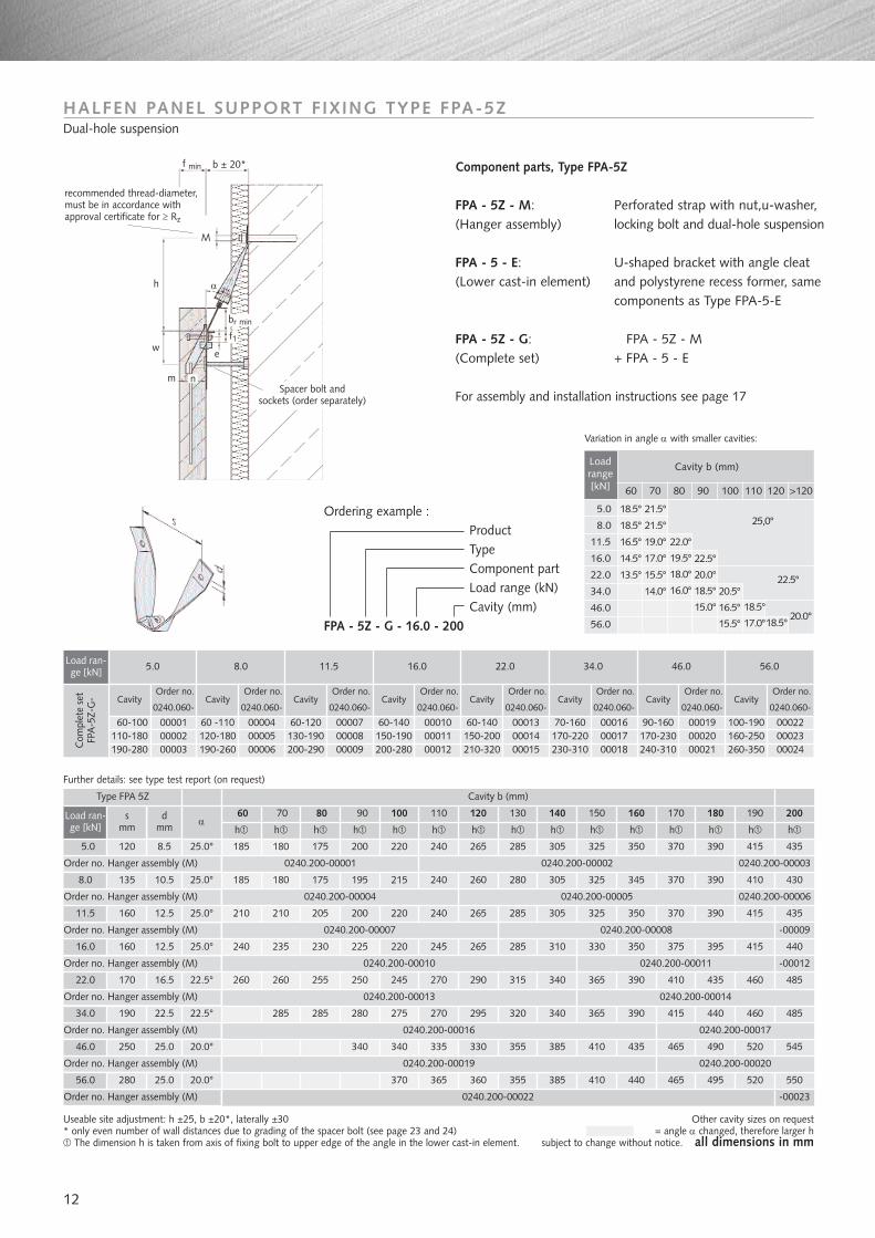
Further details: see type test report (on request)
Useable site adjustment: h ±25, b ±20*, laterally ±30* only even number of wall distances due to grading of the spacer bolt (see page 23 and 24)
The dimension h is taken from axis of fixing bolt to upper edge of the angle in the lower cast-in element.
Other cavity sizes on request= angle α changed, therefore larger h
subject to change without notice. all dimensions in mm
HALFEN PANEL SUPPORT FIXING TYPE FPA-5ZDual-hole suspension
Component parts, Type FPA-5Z
FPA - 5Z - M: Perforated strap with nut,u-washer,(Hanger assembly) locking bolt and dual-hole suspension
FPA - 5 - E: U-shaped bracket with angle cleat (Lower cast-in element) and polystyrene recess former, same
components as Type FPA-5-E
FPA - 5Z - G: FPA - 5Z - M(Complete set) + FPA - 5 - E
For assembly and installation instructions see page 17
Ordering example :ProductTypeComponent partLoad range (kN)Cavity (mm)
FPA - 5Z - G - 16.0 - 200
8.0
11.5
16.0
22.0
34.0
46.0
5.0
αh h h h h h h h h h h h h h h
25.0° 185 180 175 200 220 240 265 285 305 325 350 370 390 415 435
25.0° 185 180 175 195 215 240 260 280 305 325 345 370 390 410 430
25.0° 210 210 205 200 220 240 265 285 305 325 350 370 390 415 435
25.0° 240 235 230 225 220 245 265 285 310 330 350 375 395 415 440
22.5° 260 260 255 250 245 270 290 315 340 365 390 410 435 460 485
22.5° 285 285 280 275 270 295 320 340 365 390 415 440 460 485
20.0° 340 340 335 330 355 385 410 435 465 490 520 545
Load ran-ge [kN]
60 70 80 100 110 12090 130 140 150 170 200190180160
Type FPA 5Z Cavity b (mm)
0240.200-00001
0240.200-00004
Order no. Hanger assembly (M)
Order no. Hanger assembly (M)
Order no. Hanger assembly (M)
Order no. Hanger assembly (M)
Order no. Hanger assembly (M)
Order no. Hanger assembly (M)
0240.200-00007
0240.200-00010
0240.200-00013
0240.200-00019
0240.200-00016Order no. Hanger assembly (M)
-00009
0240.200-00003
-00012
Load ran-ge [kN] 5.0
0000160-100110-180 00002190-280 00003C
ompl
ete
set
FPA
-5Z-
G-
8.0 11.5 16.0 22.0 34.0 46.0 56.0
60 -110120-180190-260
000040000500006
000070000800009
000100001100012
000130001400015
Order no.
0240.060-
Order no.
0240.060-
Order no.
0240.060-
Order no.
0240.060-
Order no.
0240.060-
Order no.
0240.060-
Order no.
0240.060-
000160001700018
000190002000021
000220002300024
60-120130-190200-290
60-140150-190200-280
60-140150-200210-320
70-160170-220230-310
90-160170-230240-310
100-190160-250260-350
Cavity Cavity Cavity Cavity Cavity Cavity Cavity
56.0
Order no. Hanger assembly (M)
20.0° 370 365 360 355
0240.200-00022
385 410 440 465 495 520 550
CavityOrder no.
0240.060-
Spacer bolt and sockets (order separately)
w
h
f min
α
e
m n
recommended thread-diameter,must be in accordance withapproval certificate for ≥ Rz
b ± 20*
f1
br min
Variation in angle α with smaller cavities:
smm
0240.200-00002
0240.200-00008
0240.200-000060240.200-00005
0240.200-00014
0240.200-00017
0240.200-00011
0240.200-00020
-00023
120
135
160
160
170
190
250
280
dmm
8.5
10.5
12.5
12.5
16.5
22.5
25.0
25.0
M
Ordering example :ProductTypeComponent partLoad rangeCavity
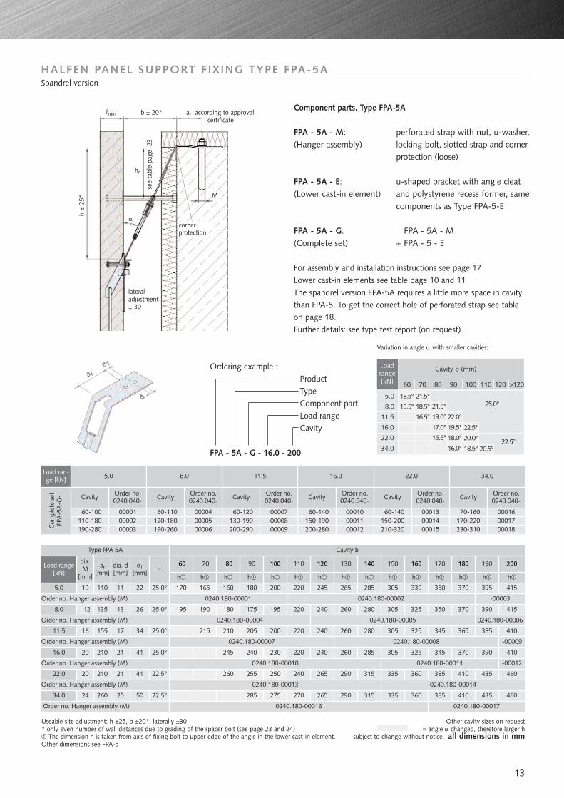
FPA - 5A - G - 16.0 - 200
Variation in angle α with smaller cavities:
Useable site adjustment: h ±25, b ±20*, laterally ±30* only even number of wall distances due to grading of the spacer bolt (see page 23 and 24)
The dimension h is taken from axis of fixing bolt to upper edge of the angle in the lower cast-in element.Other dimensions see FPA-5
Other cavity sizes on request= angle α changed, therefore larger h
subject to change without notice. all dimensions in mm
8.0
11.5
16.0
22.0
34.0
5.0
dia.M
[mm]
ar[mm] α
h h
10
12
h h h h h h h h h h h h
110 25.0° 170 165 160 200 220 245 265 285 305 330 350 370 395 415
135 25.0° 195 190 180 195 220 240 260 280 305 325 350 370 390 415
16 155 25.0° 215 210 200 220 240 260 280 305 325 345 365 385 410
20 210 25.0° 245 230 220 240 260 285 305 325 345 370 390 410
20 210 22.5° 260 250 240 265 290 315 335 360 385 410 435 460
24 260 22.5° 275 270 265 290 315 335 360 385 410 435 460
Load range[kN]
60 70 80 100 110 120 130 140 150 170 200190180160
Type FPA 5A Cavity b
0240.180-00001
0240.180-00004
Order no. Hanger assembly (M)
Order no. Hanger assembly (M)
Order no. Hanger assembly (M)
Order no. Hanger assembly (M)
Order no. Hanger assembly (M)
0240.180-00007
0240.180-00010
0240.180-00013
0240.180-00016Order no. Hanger assembly (M)
HALFEN PANEL SUPPORT FIXING TYPE FPA-5ASpandrel version
90
h
180
175
205
240
255
285
Loadrange[kN]
Cavity b (mm)
60 70 80 90 100 110 120 >120
5.0
8.0
11.5
16.0
22.0
34.0
18.5°
15.5°
21.5°
18.5°
16.5°
21.5°
19.0°
17.0°
15.5°
22.0°
19.5°
18.0°
16.0°
22.5°
20.0°
18.5° 20.5°22.5°
25.0°
Component parts, Type FPA-5A
FPA - 5A - M: perforated strap with nut, u-washer, (Hanger assembly) locking bolt, slotted strap and corner
protection (loose)
FPA - 5A - E: u-shaped bracket with angle cleat(Lower cast-in element) and polystyrene recess former, same
components as Type FPA-5-E
FPA - 5A - G: FPA - 5A - M(Complete set) + FPA - 5 - E
For assembly and installation instructions see page 17Lower cast-in elements see table page 10 and 11The spandrel version FPA-5A requires a little more space in cavitythan FPA-5. To get the correct hole of perforated strap see table on page 18.Further details: see type test report (on request).
see
tabl
e pa
ge 2
3
ar according to approval certificate
M
b ± 20*fmin
h ±
25*
hr
lateraladjustment± 30
corner protection
α
Load ran-ge [kN] 5.0
0000160-100110-180 00002190-280 00003C
ompl
ete
set
FPA
-5A
-G-
8.0 11.5 16.0 22.0 34.0
60-110120-180190-260
000040000500006
000070000800009
000100001100012
000130001400015
Order no.0240.040-
Order no.0240.040-
Order no.0240.040-
Order no.0240.040-
Order no.0240.040-
000160001700018
60-120130-190200-290
60-140150-190200-280
60-140150-200210-320
70-160170-220230-310
Cavity Cavity Cavity Cavity CavityOrder no.0240.040-Cavity
13
0240.180-00002
0240.180-00005 0240.180-00006
0240.180-00008 -00009
0240.180-00011 -00012
0240.180-00014
0240.180-00017
dia. d[mm]
11
13
17
21
21
25
e1[mm]
22
26
34
41
41
50
-00003
ar according to approval certificate
fmin b ± 20*
h ±
25*
hr
lateraladjustment± 30
corner protection
α
14
Load range[kN] 5.0
0000160-100110-180 00002190-280 00003C
ompl
ete
set
FPA
-5A
Z-G
-
8.0 11.5 16.0 22.0 34.0
60-110120-180190-260
000040000500006
000070000800009
000100001100012
000130001400015
Order no.0240.070-
Order no.0240.070-
Order no.0240.070-
Order no.0240.070-
Order no.0240.070-
000160001700018
60-120130-190200-290
60-140150-190200-280
60-140150-200210-320
70-160170-220230-310
Cavity Cavity Cavity Cavity Cavity
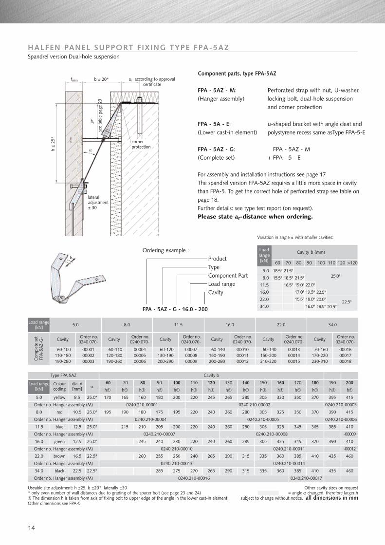
Useable site adjustment: h ±25, b ±20*, laterally ±30* only even number of wall distances due to grading of the spacer bolt (see page 23 and 24)
The dimension h is taken from axis of fixing bolt to upper edge of the angle in the lower cast-in element.Other dimensions see FPA-5
Other cavity sizes on request= angle α changed, therefore larger h
subject to change without notice. all dimensions in mm
Loadrange[kN]
Cavity b (mm)
60 70 80 90 100 110 120 >120
5.0
8.0
11.5
16.0
22.0
34.0
18.5°
15.5°
21.5°
18.5°
16.5°
21.5°
19.0°
17.0°
15.5°
22.0°
19.5°
18.0°
16.0°
22.5°
20.0°
18.5° 20.5°22.5°
25.0°
Ordering example :ProductTypeComponent PartLoad rangeCavity
FPA - 5AZ - G - 16.0 - 200
Component parts, type FPA-5AZ
FPA - 5AZ - M: Perforated strap with nut, U-washer,(Hanger assembly) locking bolt, dual-hole suspension
and corner protection
FPA - 5A - E: u-shaped bracket with angle cleat and (Lower cast-in element) polystyrene recess same asType FPA-5-E
FPA - 5AZ - G: FPA - 5AZ - M(Complete set) + FPA - 5 - E
For assembly and installation instructions see page 17The spandrel version FPA-5AZ requires a little more space in cavitythan FPA-5. To get the correct hole of perforated strap see table onpage 18.Further details: see type test report (on request). Please state ar-distance when ordering.
HALFEN PANEL SUPPORT FIXING TYPE FPA-5AZSpandrel version Dual-hole suspension
yellow
red
Colourcoding
dia. d[mm] α
h h
blue
green
brown
black
8.5
10.5
h h h h h h h h h h h h
25.0° 170 165 160 200 220 245 265 285 305 330 350 370 395 415
25.0° 195 190 180 195 220 240 260 280 305 325 350 370 390 415
12.5 25.0° 215 210 200 220 240 260 280 305 325 345 365 385 410
12.5 25.0° 245 230 220 240 260 285 305 325 345 370 390 410
16.5 22.5° 260 250 240 265 290 315 335 360 385 410 435 460
22.5 22.5° 275 270 265 290 315 335 360 385 410 435 460
60 70 80 100 110 120 130 140 150 170 200190180160
Cavity b
0240.210-00001
0240.210-00004
0240.210-00007
0240.210-00010
0240.210-00013
0240.210-00016
90
h
180
175
205
240
255
285
Cavity Order no.0240.070-
Variation in angle α with smaller cavities:
0240.210-00002 0240.210-00003
0240.210-000060240.210-00005
0240.210-00008 -00009
0240.210-00011 -00012
0240.210-00014
0240.210-00017
d
see
tabl
e pa
ge 2
3
Load range[kN]
5.0
8.0
11.5
16.0
22.0
34.0
Order no. Hanger assembly (M)
Order no. Hanger assembly (M)
Order no. Hanger assembly (M)
Order no. Hanger assembly (M)
Order no. Hanger assembly (M)
Order no. Hanger assembly (M)
Type FPA 5AZ
15
Load range[kN] 3.0
0000180-180190-200 00002C
ompl
ete
set
FPA
-S-G
-
6.0
80-180190-200
0000300004
Order no.0240.010-CavityOrder no.
0240.010-Cavity
6.0
5.0
8.0
3.0
Marking
HTA 28/15(A4)
HTA 38/17(A4)
h h h h h h h h h h h h h
HTA 28/15(A4) 3.0 kN 200 220 240 260 280 300 330 350 370 390 410 430 450
HTA 38/17(A4) 6.0kN 200 220 240 260 280 300 330 350 370 390 410 430 450
Load range [kN]
80 100 110 12090 130 140 150 170 200190180160
Type
Order no. Hanger assembly (M)
Order no. Hanger assembly (M)
-00002
-00004
FPA-S-ELower cast-in
elementHalfen channel
FPA-S-RCast-in supportHalfen channel
FPA-S-MHanger assembly
0240.150-00003
0240.150-00001
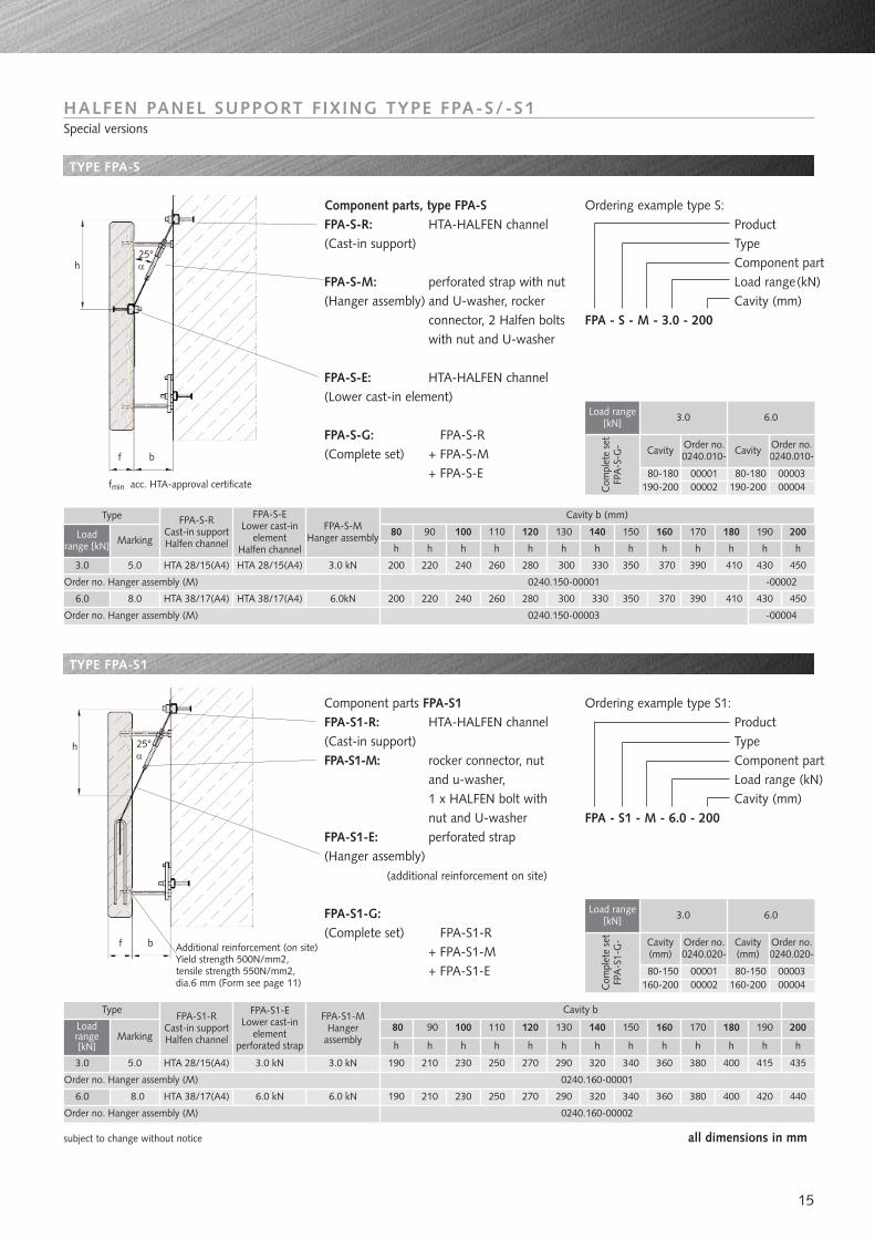
HALFEN PANEL SUPPORT FIXING TYPE FPA-S/-S1Special versions
Ordering example type S:ProductTypeComponent partLoad range(kN)Cavity (mm)
FPA - S - M - 3.0 - 200
TYPE FPA-S
TYPE FPA-S1
6.0
5.0
8.0
3.0
Marking
HTA 28/15(A4)
HTA 38/17(A4)
h h h h h h h h h h h h h
3.0 kN 190 210 230 250 270 290 320 340 360 380 400 415 435
6.0 kN 190 210 230 250 270 290 320 340 360 380 400 420 440
Load range[kN]
80 100 110 12090 130 140 150 170 200190180160
Type
Order no. Hanger assembly (M)
Order no. Hanger assembly (M)
FPA-S1-RCast-in supportHalfen channel
FPA-S1-ELower cast-in
elementperforated strap
0240.160-00002
0240.160-00001
Component parts, type FPA-SFPA-S-R: HTA-HALFEN channel(Cast-in support)
FPA-S-M: perforated strap with nut(Hanger assembly) and U-washer, rocker
connector, 2 Halfen bolts with nut and U-washer
FPA-S-E: HTA-HALFEN channel(Lower cast-in element)
FPA-S-G: FPA-S-R(Complete set) + FPA-S-M
+ FPA-S-E
Component parts FPA-S1FPA-S1-R: HTA-HALFEN channel(Cast-in support)FPA-S1-M: rocker connector, nut
and u-washer, 1 x HALFEN bolt with nut and U-washer
FPA-S1-E: perforated strap(Hanger assembly)
(additional reinforcement on site)
FPA-S1-G:(Complete set) FPA-S1-R
+ FPA-S1-M+ FPA-S1-E
Ordering example type S1:ProductTypeComponent partLoad range (kN)Cavity (mm)
FPA - S1 - M - 6.0 - 200
Load range[kN] 3.0
00001
Cavity(mm)
80-150160-200 00002C
ompl
ete
set
FPA
-S1-
G-
6.0
80-150160-200
0000300004
Order no.0240.020-
Cavity(mm)
Order no.0240.020-
Cavity b (mm)
Cavity b
subject to change without notice all dimensions in mm
h25°α
bf
25°α
f
h
b Additional reinforcement (on site)Yield strength 500N/mm2,tensile strength 550N/mm2,dia.6 mm (Form see page 11)
3.0 kN
6.0 kN
FPA-S1-MHanger
assembly
fmin acc. HTA-approval certificate
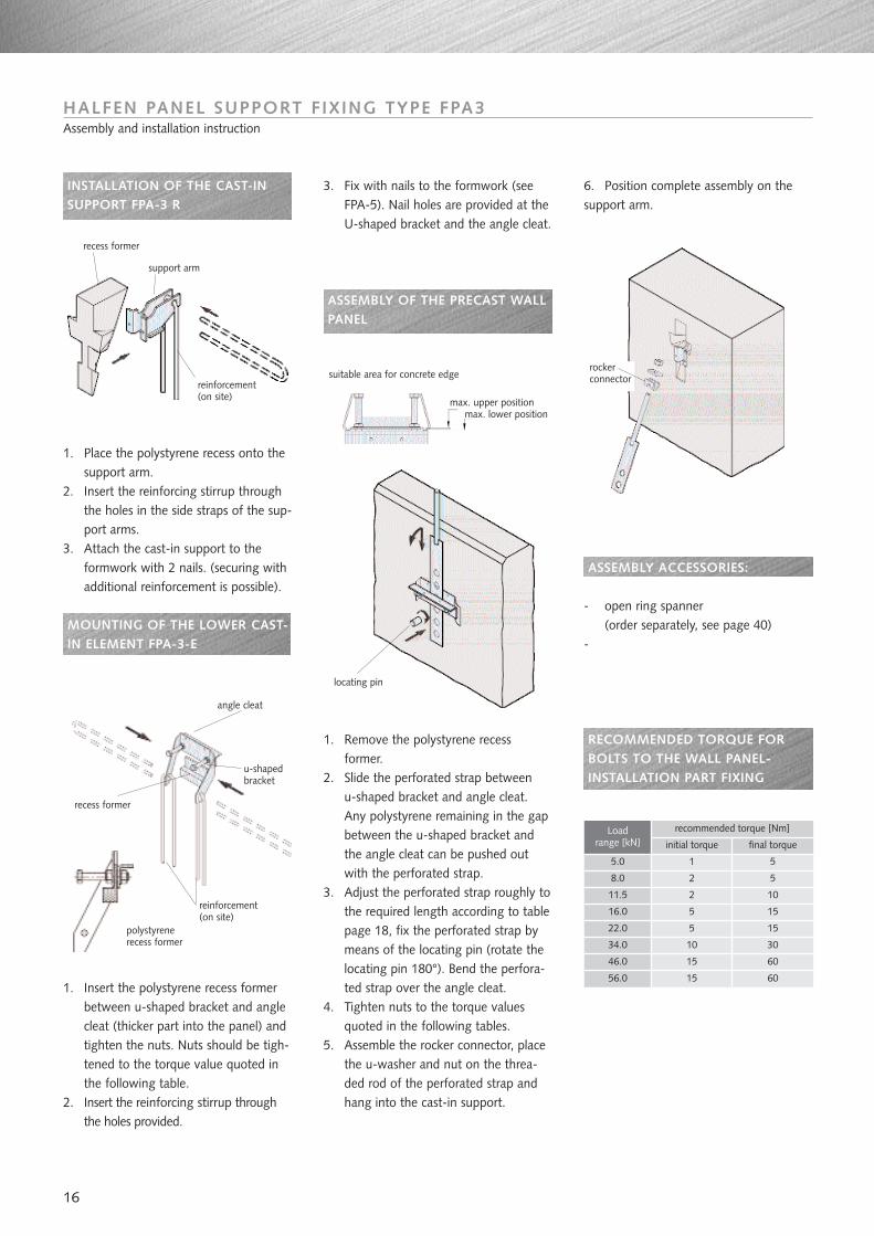
INSTALLATION OF THE CAST-INSUPPORT FPA-3 R
1. Place the polystyrene recess onto thesupport arm.
2. Insert the reinforcing stirrup throughthe holes in the side straps of the sup-port arms.
3. Attach the cast-in support to theformwork with 2 nails. (securing withadditional reinforcement is possible).
MOUNTING OF THE LOWER CAST-IN ELEMENT FPA-3-E
1. Insert the polystyrene recess formerbetween u-shaped bracket and anglecleat (thicker part into the panel) andtighten the nuts. Nuts should be tigh-tened to the torque value quoted inthe following table.
2. Insert the reinforcing stirrup throughthe holes provided.
16
3. Fix with nails to the formwork (seeFPA-5). Nail holes are provided at theU-shaped bracket and the angle cleat.
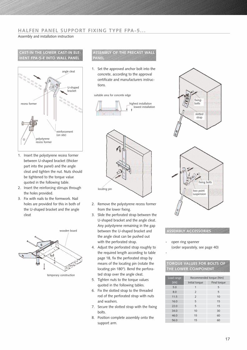
ASSEMBLY OF THE PRECAST WALLPANEL
1. Remove the polystyrene recessformer.
2. Slide the perforated strap betweenu-shaped bracket and angle cleat.Any polystyrene remaining in the gapbetween the u-shaped bracket andthe angle cleat can be pushed outwith the perforated strap.
3. Adjust the perforated strap roughly tothe required length according to tablepage 18, fix the perforated strap bymeans of the locating pin (rotate thelocating pin 180°). Bend the perfora-ted strap over the angle cleat.
4. Tighten nuts to the torque valuesquoted in the following tables.
5. Assemble the rocker connector, placethe u-washer and nut on the threa-ded rod of the perforated strap andhang into the cast-in support.
HALFEN PANEL SUPPORT FIXING TYPE FPA3Assembly and installation instruction
5.0
8.0
11.5
16.0
22.0
34.0
46.0
56.0
1
2
2
5
5
10
15
15
5
5
10
15
15
60
60
30
Loadrange [kN]
recommended torque [Nm]
initial torque final torque
6. Position complete assembly on thesupport arm.
ASSEMBLY ACCESSORIES:
- open ring spanner(order separately, see page 40)
-
RECOMMENDED TORQUE FORBOLTS TO THE WALL PANEL-INSTALLATION PART FIXING
reinforcement(on site)
reinforcement(on site)
recess former
angle cleat
support arm
recess former
suitable area for concrete edge
max. upper positionmax. lower position
rockerconnector
locating pin
polystyrenerecess former
u-shapedbracket
ASSEMBLY OF THE PRECAST WALLPANEL
1. Set the approved anchor bolt into theconcrete, according to the approvalcertificate and manufacturers instruc-tions.
2. Remove the polystyrene recess formerfrom the lower fixing.
3. Slide the perforated strap between theU-shaped bracket and the angle cleat.Any polystyrene remaining in the gapbetween the U-shaped bracket andthe angle cleat can be pushed outwith the perforated strap.
4. Adjust the perforated strap roughly tothe required length according to tablepage 18, fix the perforated strap bymeans of the locating pin (rotate thelocating pin 180°). Bend the perfora-ted strap over the angle cleat.
5. Tighten nuts to the torque valuesquoted in the following tables.
6. Fix the slotted strap to the threadedrod of the perforated strap with nutsand washers.
7. Secure the slotted strap with the fixingbolts.
8. Position complete assembly onto thesupport arm.
CAST-IN THE LOWER CAST-IN ELE-MENT FPA-5-E INTO WALL PANEL
1. Insert the polystyrene recess formerbetween U-shaped bracket (thickerpart into the panel) and the anglecleat and tighten the nut. Nuts shouldbe tightened to the torque valuequoted in the following table.
2. Insert the reinforcing stirrups throughthe holes provided.
3. Fix with nails to the formwork. Nailholes are provided for this in both ofthe U-shaped bracket and the anglecleat
17
HALFEN PANEL SUPPORT FIXING TYPE FPA-5. . .Assembly and installation instruction
5.0
8.0
11.5
16.0
22.0
34.0
46.0
56.0
1
2
2
5
5
10
15
15
5
5
10
15
15
60
60
30
Load range
[kN]
Recommended torque [Nm]
Initial torque Final torque
ASSEMBLY ACCESSORIES
- open ring spanner(order separately, see page 40)
-
TORQUE VALUES FOR BOLTS OFTHE LOWER COMPONENT
reinforcement(on site)
polystyrenerecess former
U-shapedbracket
recess former
wooden board
temporary construction
locating pin
highest installationlowest installation
suitable area for concrete edge
fixing-bolts
slottedstrap
fixing bolts
two pointsuspension
angle cleat
18
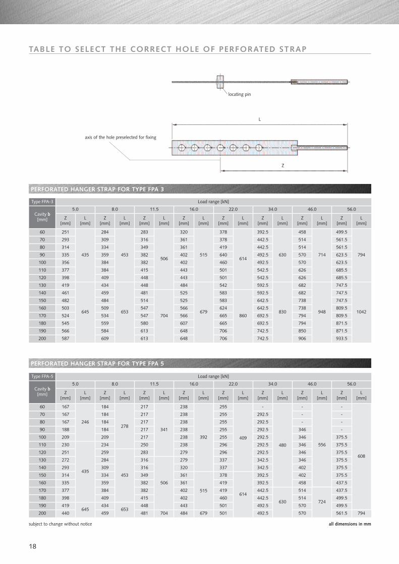
TABLE TO SELECT THE CORRECT HOLE OF PERFORATED STRAP
60
70
80
90
100
110
120
130
140
150
160
170
180
190
200
251
293
314
335
356
377
398
419
461
482
503
524
545
566
587
284
309
334
359
384
384
409
434
459
484
509
534
559
584
609
283
316
349
382
382
415
448
448
481
514
547
547
580
613
613
320
361
361
402
402
443
443
484
525
525
566
566
607
648
648
378
378
419
640
460
501
501
542
583
583
624
665
665
706
706
392.5
442.5
442.5
492.5
492.5
542.5
542.5
592.5
592.5
642.5
642.5
692.5
692.5
742.5
742.5
5.0 8.0 11.5 16.0 22.0
458
514
514
570
570
626
626
682
682
738
738
794
794
850
906
34.0
Z[mm]
L[mm]
L[mm]
46.0Cavity b
[mm]
Type FPA-3
L[mm]
Z[mm]
Z[mm]
56.0
499.5
561.5
561.5
623.5
623.5
685.5
685.5
747.5
747.5
747.5
809.5
809.5
871.5
871.5
933.5
794
1042
714
948
630
830
614
860
515
679
Z[mm]
Z[mm]
Z[mm]
Z[mm]
Z[mm]
L[mm]
L[mm]
L[mm]
L[mm]
L[mm]
435
645
453
653
506
704
Load range [kN]
subject to change without notice all dimensions in mm
60
70
80
90
100
110
120
130
140
150
160
170
180
190
200
167
167
167
188
209
230
251
272
293
314
335
377
398
419
440
184
184
184
184
209
234
259
284
309
334
359
384
409
434
459
217
217
217
217
217
250
283
316
316
349
382
382
415
448
481
238
238
238
238
238
238
279
279
320
361
361
402
402
443
484
255
255
255
255
255
296
296
337
337
378
419
419
460
501
501
-
292.5
292.5
292.5
292.5
292.5
292.5
342.5
342.5
392.5
392.5
442.5
442.5
492.5
492.5
5.0 8.0 11.5 16.0 22.0
-
-
-
346
346
346
346
346
402
402
458
514
514
570
570
34.0
Z[mm]
L[mm]
L[mm]
46.0Cavity b
[mm]
Type FPA-5
L[mm]
Z[mm]
Z[mm]
56.0
-
-
-
-
375.5
375.5
375.5
375.5
375.5
375.5
437.5
437.5
499.5
499.5
561.5
608
556480
409392
Z[mm]
Z[mm]
Z[mm]
Z[mm]
Z[mm]
L[mm]
L[mm]
L[mm]
L[mm]
L[mm]
246278
341
Load range [kN]
PERFORATED HANGER STRAP FOR TYPE FPA 5
PERFORATED HANGER STRAP FOR TYPE FPA 3
645
453
653704
515
679
614
630 724
794
Z
L
locating pin
axis of the hole preselected for fixing
435
506
19
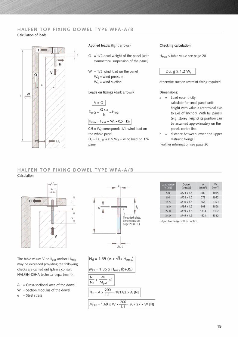
HALFEN TOP FIXING DOWEL TYPE WPA-A/BCalculation of loads
HALFEN TOP FIXING DOWEL TYPE WPA-A/BCalculation
Applied loads: (light arrows)
Q = 1/2 dead weight of the panel (withsymmetrical suspension of the panel)
W = 1/2 wind load on the panelWd = wind pressureWs = wind suction
Loads on fixings (dark arrows)
V = Q
0.5 x Ws corresponds 1/4 wind load onthe whole panelDu = Du, Q + 0.5 Wd = wind load on 1/4panel
exzQ,u Hh
axQD ==
osexzmax D5,0xWHH =+=
Checking calculation:
Hmax ≤ table value see page 20
otherwise suction restraint fixing required.
Dimensions:a = Load eccentricity
calculate for small panel unitheight with value a (centroidal axisto axis of anchor). With tall panels(e.g. storey height) its position canbe assumed approximately on thepanels centre line.
h = distance between lower and upperrestraint fixings
Further information see page 20
Du. g ≥ 1.2 Ws
The table values V or Hexz and/or Hmax
may be exceeded providing the followingchecks are carried out (please consultHALFEN-DEHA technical department):
A = Cross-sectional area of the dowelW = Section modulus of the dowelσ = Steel stress
Load rangeV [kN]
Dowel[thread]
A[mm2]
W[mm3]
5.0
8.0
11.5
16.0
22.0
34.0
1045
8362
5387
3858
2393
1932
M24 x 1.5
M28 x 1.5
M30 x 1.5
M35 x 1.5
M39 x 1.5
M45 x 1.5
380
573
661
908
1134
1521
subject to change without notice.
edia. p
r
lgg
t
b
c
V
H
lThreaded plate, dimensions see page 20 (r )
dia. d
hW
Du
V
H
Q
a
Hz
N M+ <1
Nd Mpld
Nd = 1.35 (V + √3x Hmax)
Md = 1.35 x Hmax (b+35)
200Nd = A x = 181.82 x A [N]
1.1
200Mpld = 1.69 x W x = 307.27 x W [N]
1.1
b
20
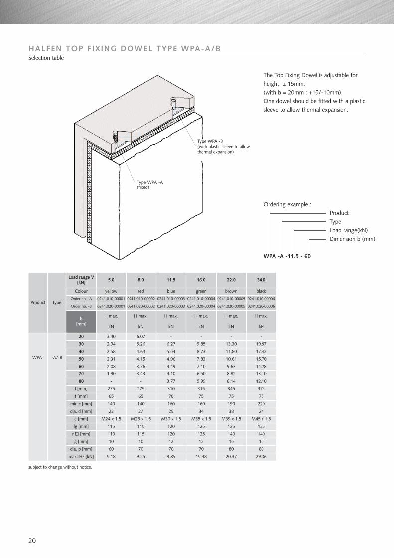
HALFEN TOP FIXING DOWEL TYPE WPA-A/BSelection table
20
30
40
50
60
70
80
l [mm]
t [mm]
min c [mm]
dia. d [mm]
e [mm]
lg [mm]
r [mm]
g [mm]
dia. p [mm]
max. Hz [kN]
3.40 6.07 - - - -
Load range V[kN] 5.0 8.0 11.5 16.0 22.0 34.0
Colour yellow red blue
0241.010-00001 0241.010-00002 0241.010-00003Order no. -AProduct Type
Order no. -B 0241.020-00001 0241.020-00002 0241.020-00003
b[mm]
H max.
kN
H max.
kN
H max.
kN
H max.
kN
H max.
kN
H max.
kN
0241.010-00004
green brown
0241.010-00005
black
0241.010-00006
0241.020-00004 0241.020-00005 0241.020-00006
2.94
2.58
2.31
2.08
1.90
-
5.26
4.64
4.15
3.76
3.43
-
275
65
140
22
M24 x 1.5
115
110
10
60
5.18
140
275
65
27
M28 x 1.5
115
115
10
70
9.25
310
70
160
29
M30 x 1.5
120
120
12
70
9.85
315
75
160
34
M35 x 1.5
125
125
12
70
15.48
345 375
75 75
190 220
38 24
M39 x 1.5 M45 x 1.5
125 125
140 140
15 15
80 80
20.37 29.36
6.27
5.54
4.96
4.49
4.10
3.77
9.85
8.73
7.83
7.10
6.50
5.99
13.30
11.80
10.61
9.63
8.82
8.14
19.57
17.42
15.70
14.28
13.10
12.10
WPA- -A/-B
Ordering example :ProductTypeLoad range(kN)Dimension b (mm)
WPA -A -11.5 - 60
The Top Fixing Dowel is adjustable forheight ± 15mm.(with b = 20mm : +15/-10mm). One dowel should be fitted with a plasticsleeve to allow thermal expansion.
subject to change without notice.
Type WPA -A(fixed)
Type WPA -B(with plastic sleeve to allowthermal expansion)
21
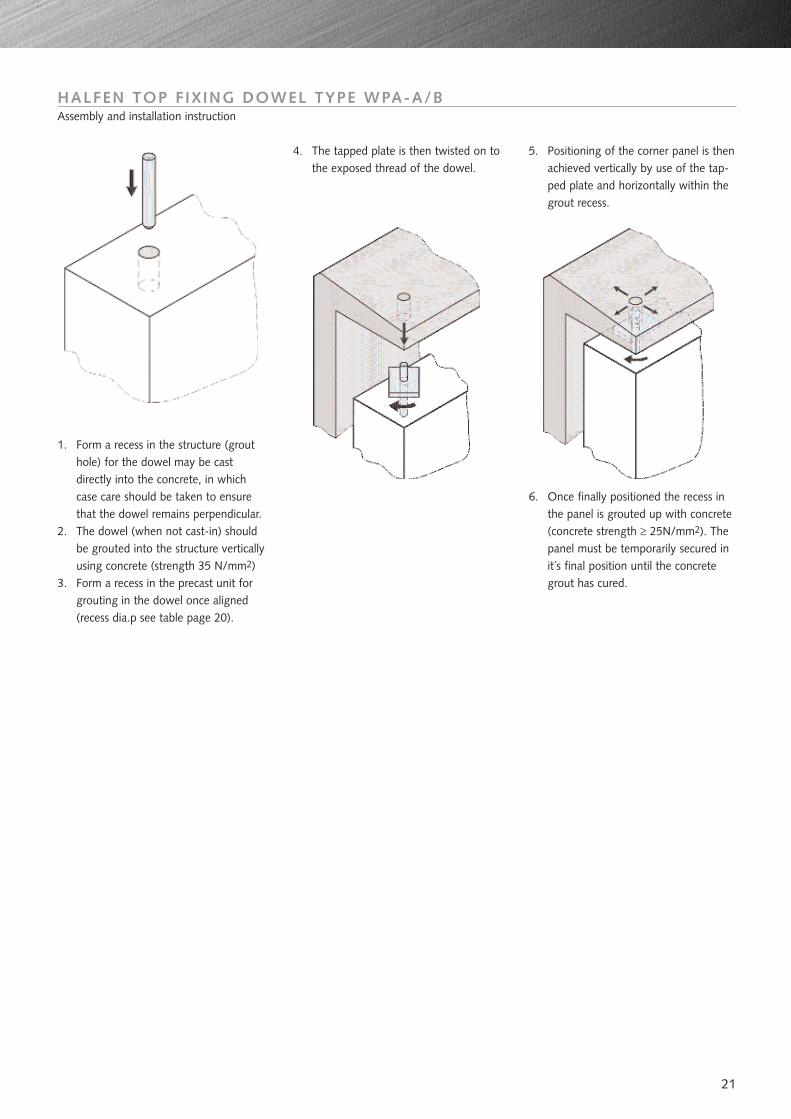
HALFEN TOP FIXING DOWEL TYPE WPA-A/BAssembly and installation instruction
1. Form a recess in the structure (grouthole) for the dowel may be castdirectly into the concrete, in whichcase care should be taken to ensurethat the dowel remains perpendicular.
2. The dowel (when not cast-in) shouldbe grouted into the structure verticallyusing concrete (strength 35 N/mm2)
3. Form a recess in the precast unit forgrouting in the dowel once aligned(recess dia.p see table page 20).
4. The tapped plate is then twisted on tothe exposed thread of the dowel.
5. Positioning of the corner panel is thenachieved vertically by use of the tap-ped plate and horizontally within thegrout recess.
6. Once finally positioned the recess inthe panel is grouted up with concrete(concrete strength ≥ 25N/mm2). Thepanel must be temporarily secured init´s final position until the concretegrout has cured.
22
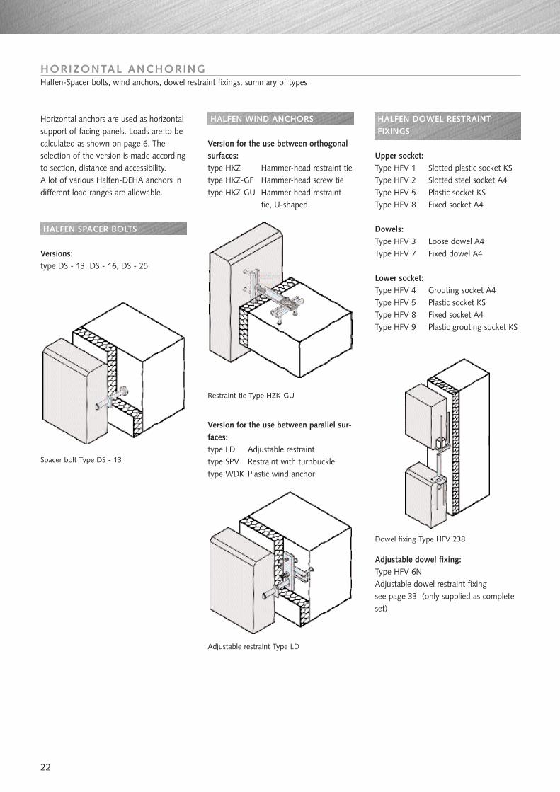
HORIZONTAL ANCHORINGHalfen-Spacer bolts, wind anchors, dowel restraint fixings, summary of types
Horizontal anchors are used as horizontalsupport of facing panels. Loads are to becalculated as shown on page 6. Theselection of the version is made accordingto section, distance and accessibility. A lot of various Halfen-DEHA anchors indifferent load ranges are allowable.
HALFEN SPACER BOLTS
Versions:type DS - 13, DS - 16, DS - 25
Spacer bolt Type DS - 13
HALFEN WIND ANCHORS
Version for the use between orthogonalsurfaces:type HKZ Hammer-head restraint tietype HKZ-GF Hammer-head screw tietype HKZ-GU Hammer-head restraint
tie, U-shaped
Restraint tie Type HZK-GU
Version for the use between parallel sur-faces:type LD Adjustable restrainttype SPV Restraint with turnbuckletype WDK Plastic wind anchor
Adjustable restraint Type LD
HALFEN DOWEL RESTRAINTFIXINGS
Upper socket:Type HFV 1 Slotted plastic socket KSType HFV 2 Slotted steel socket A4Type HFV 5 Plastic socket KSType HFV 8 Fixed socket A4
Dowels:Type HFV 3 Loose dowel A4Type HFV 7 Fixed dowel A4
Lower socket:Type HFV 4 Grouting socket A4Type HFV 5 Plastic socket KSType HFV 8 Fixed socket A4Type HFV 9 Plastic grouting socket KS
Dowel fixing Type HFV 238
Adjustable dowel fixing:Type HFV 6NAdjustable dowel restraint fixingsee page 33 (only supplied as completeset)
23
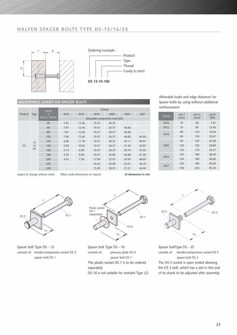
HALFEN SPACER BOLTS TYPE DS-13/16/25
Ordering example :ProductTypeThreadCavity b (mm)
DS-13-10-100
Thread min f[mm]
min hr[mm]
zul.N[kN]
70
70
50
90
7.81
12.46
M10
M12
90
80M16
120
120
16.64
19.47
90
100
120
M20
120
150M24
120
150M27
135
150
170
180
180
180
225
24.48
28.80
36.37
38.40
46.60
38.40
55.20
Allowable loads and edge distances forSpacer bolts by using without additionalreinforcement
subject to change without notice Other cavity dimensions on request all dimensions in mm
ALLOWABLE LOADS ON SPACER BOLTS
40
60
80
100
120
140
160
180
200
220
240
M10 M12 M16 M20 M24 M27Product TypeCavity
b[mm] ± 20mm
Thread
Allowable compressive load [kN]
44.00
DS131625
7.81
7.81
7.81
7.60
6.65
5.83
5.14
4.54
4.02
-
-
12.46
12.46
12.46
12.46
11.18
10.02
8.99
8.09
7.30
-
-
19.47
19.47
19.47
19.47
19.47
19.47
19.47
19.47
17.99
16.63
15.39
36.37
36.37
36.37
36.37
36.37
36.37
36.37
34.83
32.57
30.49
28.57
-
46.60
46.60
46.60
44.11
41.56
39.19
36.98
34.93
33.01
31.21
-
-
-
60.60
59.91
56.81
53.92
51.20
48.65
46.25
Spacer bolt Type DS - 13consists of: tensile/compressive socket DS 3
spacer bolt DS 1
Spacer bolt Type DS - 16consists of: pressure plate DS 6
spacer bolt DS 1
The plastic socket DS 7 is to be orderedseparately.DS-16 is not suitable for restraint Type LD.
Spacer boltType DS - 25consists of: tensile/compressive socket DS 5
spacer bolt DS 2
The DS 5 socket is open ended allowingthe DS 2 bolt, which has a slot in this endof its shank to be adjusted after assembly.
f b
hr
L
L
LH
DS 3 DS 1DS 5
L
LH
DS 2
Plastic socketDS 7 (separately)
DS 6
DS 1
LH
24
40
60
80
100
120
160
180
200
220
240
70
90
110
130
150
170
190
210
230
-
-
90
110
130
150
170
190
210
230
250
-
-
72 92 75 95 80 100 - - - -
LDS-13/-25
LDS-16
M10Cavityb
[mm] ± 20mmL
DS-13/-25L
DS-13/-25L
DS-13/-25L
DS-13/-25L
DS-13/-25L
DS-16L
DS-16L
DS-16L
DS-16L
DS-16
M12 M16 M20 M24 M27
92 112 95 115 100 120 105 125 _ -
112 132 115 135 120 140 125 145 - -
132 152 135 155 140 160 145 165 145 165
152 172 155 175 160 180 165 185 165 185
140 172 192 175 195 180 200 185 205 185 205
192 212 195 215 200 220 205 225 205 225
212 232 215 235 220 240 225 245 225 245
232 252 235 255 240 260 245 265 245 265
- - 255 275 260 280 265 285 265 285
- - 275 295 280 300 285 305 285 305
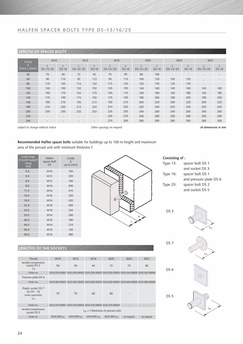
LENGTH OF SPACER BOLTS
subject to change without notice Other spacings on request all dimensions in mm
HALFEN SPACER BOLTS TYPE DS-13/16/25
LENGTHS OF THE SOCKETS
Thread M10 M12 M16 M20 M24 M27tensile/compressive
socket DS 3LH
Plastic socket DS 7for DS - 16
(order separately)LH
tensile/compressivesocket DS 5
58 59 64 72 75 80
70 70 80 80 - -
LH = f (thickness of precast unit)
Consisting of :Type 13: spacer bolt DS 1
and socket DS 3Type 16: spacer bolt DS 1
and pressure plate DS 6Type 25: spacer bolt DS 2
and socket DS 5
Load rangeof panel support
fixing[kN]
Halfenspacer bolt
DS
Cavityb
up to [mm]
5.0
8.0
5.0
8.0
11.5
16.0
16.0
22.0
34.0
34.0
46.0
46.0
56.0
56.0
M10
M12
M12
M16
M16
M16
M16
M16
M16
M16
M16
M16
M16
M16
150
250
160
390
310
220
420
350
230
260
180
210
150
380
Recommended Halfen spacer bolts suitable for buildings up to 100 m height and maximumarea of the precast unit with minimum thickness f.
f
b
0243.030-00001Order-no. 0243.030-00002 0243.030-00003 0243.030-00004 0243.030-00005 0243.030-00006
Pressure plate DS 6
Order-no. 0243.060-00001 0243.060-00002 0243.060-00003 0243.060-00004 0243.060-00005 0243.060-00006
Order-no. 0243.070-00001 0243.070-00002 0243.070-00003 0243.070-00004 - -
Order-no. 0243.050-LH 0243.050-LH 0243.050-LH 0243.050-LH on request on request
LH
LH
LH
DS 3
DS 7
DS 6
DS 5
25
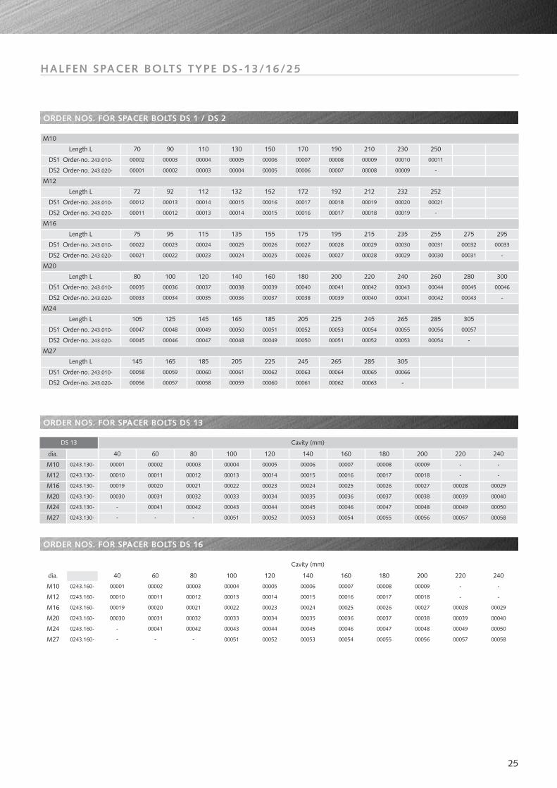
ORDER NOS. FOR SPACER BOLTS DS 1 / DS 2
ORDER NOS. FOR SPACER BOLTS DS 13
ORDER NOS. FOR SPACER BOLTS DS 16
HALFEN SPACER BOLTS TYPE DS-13/16/25
Length L
DS1 Order-no. 243.010-
DS2 Order-no. 243.020-
M12
70 90 110 130 150 170 190 210 230 250
M16
M20
M24
M27
M10
00002
DS1 Order-no. 243.010-
DS1 Order-no. 243.010-
Length L
DS1 Order-no. 243.010-
Length L
DS1 Order-no. 243.010-
Length L
Length L
Length L
DS2 Order-no. 243.020-
DS2 Order-no. 243.020-
DS2 Order-no. 243.020-
DS2 Order-no. 243.020-
DS2 Order-no. 243.020-
DS1 Order-no. 243.010-
00001 00002 00003 00004 00005 00006 00007 00008 00009 -
00018 00019 -
00028 00029 00030
00040 00041
00041
00039 00042
00003 00004 00005 00006 00007 00008
00013 00014 00015 00016 00017 00018
00023 00024 00025 00026 00027 00028 00029 00030
100 120 140
000380003700036 00039
180
00040 00042
240
00043
75 95 115 135 155 175 195 215 235 255 275 295
00012
105
00047 00048
145
00049 00050 00051 00052 00053
00009 00010 00011
00019 00020 00021
252
00031 00032 00033
72 92 112 132 152 172 192 212 232
80 160 200 220 260 280 300
00022
00035
00011 00012 00013 00014 00015 00016 00017
00021 00022 00023 00024 00025 00026 00027 00031 -
0004300033 00034 00035 00036 00037 00038 -
00044 00045 00046
125 165 185 205 225 245 265 285 305
00045 00046 00047 00048 00049 00050 00051
00054
00052
00055 00056 00057
00053 00054 -
145 165 185 205 225 245 265 285 305
00058 00059 00060 00061 00062 00063 00064 00065 00066
00056 00057 00058 00059 00060 00061 00062 00063 -
40 60 80 100 120 140 160 180 200 220
00001 00002 00003 00004 00005 00006 00007 00008 00009 -
00010 00011 00012 00013 00014 00015 00016 00017 00018 -
- 00041 00042 00043 00044 00045 00046 00047 00048 00049
00030 00031 00032 00033 00034 00035 00036 00037 00038 00039
00019 00020 00021 00022 00023 00024 00025 00026 00027 00028
- - - 00051 00052 00053 00054 00055 00056 00057
00050
00058
Cavity (mm)
240
00029
00040
-
-
DS 13
M10
M12
M16
M20
M24
M27
dia.
0243.130-
0243.130-
0243.130-
0243.130-
0243.130-
0243.130-
40 60 80 100 120 140 160 180 200 220
00001 00002 00003 00004 00005 00006 00007 00008 00009 -
00010 00011 00012 00013 00014 00015 00016 00017 00018 -
- 00041 00042 00043 00044 00045 00046 00047 00048 00049
00030 00031 00032 00033 00034 00035 00036 00037 00038 00039
00019 00020 00021 00022 00023 00024 00025 00026 00027 00028
- - - 00051 00052 00053 00054 00055 00056 00057
00050
00058
Cavity (mm)
240
00029
00040
-
-
DS 16
M10
M12
M16
M20
M24
M27
dia.
0243.160-
0243.160-
0243.160-
0243.160-
0243.160-
0243.160-
26
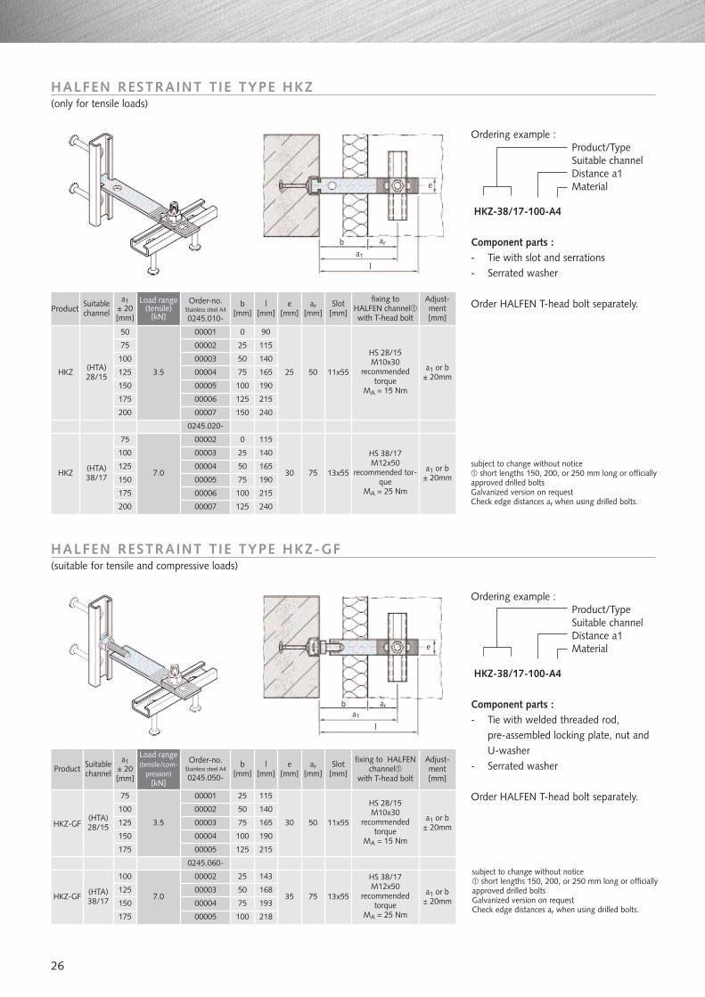
HALFEN RESTRAINT TIE TYPE HKZ(only for tensile loads)
HALFEN RESTRAINT TIE TYPE HKZ-GF(suitable for tensile and compressive loads)
Ordering example :Product/Type Suitable channelDistance a1Material
HKZ-38/17-100-A4
Component parts :- Tie with slot and serrations- Serrated washer
Order HALFEN T-head bolt separately.
Ordering example :Product/Type Suitable channelDistance a1Material
HKZ-38/17-100-A4
Component parts :- Tie with welded threaded rod,
pre-assembled locking plate, nut andU-washer
- Serrated washer
Order HALFEN T-head bolt separately.
HKZ
HKZ
50
75
100
125
150
175
200
75
100
125
150
3.5
7.0
0 90
25 50 11x55
HS 28/15M10x30
recommendedtorque
MA = 15 Nm
a1 or b± 20mm
a1± 20[mm]
Load range(tensile)
[kN]
b[mm]
e[mm]
Slot[mm]
Adjust-ment[mm]
l[mm]
ar[mm]
fixing to HALFEN channelwith T-head bolt
25 115
50 140
75 165
100 190
125 215
150 240
0 115
30 75 13x55
HS 38/17M12x50
recommended tor-que
MA = 25 Nm
a1 or b± 20mm
25 140
50 165
75 190
Product
175
200
Suitablechannel
(HTA)28/15
(HTA)38/17
100
125 240
215
HKZ-GF
HKZ-GF
75
100
125
150
175
100
125
150
175
3.5
7.0
25 115
30 50 11x55
HS 28/15M10x30
recommendedtorque
MA = 15 Nm
a1 or b± 20mm
a1± 20[mm]
Load range(tensile/com-
pression)[kN]
b[mm]
e[mm]
Slot[mm]
Adjust-ment[mm]
l[mm]
ar[mm]
fixing to HALFENchannel
with T-head bolt
50 140
75 165
100 190
125 215
25 143
35 75 13x55
HS 38/17M12x50
recommended torque
MA = 25 Nm
a1 or b± 20mm
50 168
75 193
100 218
Product Suitablechannel
(HTA)28/15
(HTA)38/17
subject to change without notice short lengths 150, 200, or 250 mm long or officially
approved drilled boltsGalvanized version on requestCheck edge distances ar when using drilled bolts.
subject to change without notice short lengths 150, 200, or 250 mm long or officially
approved drilled boltsGalvanized version on requestCheck edge distances ar when using drilled bolts.
b
e
l
a1
ar
b
e
l
a1
ar
Order-no.Stainless steel A4
0245.010-
00001
00002
00003
00004
00005
00006
00007
00002
00003
00004
00005
00006
00007
Order-no.Stainless steel A4
0245.050-
00001
00002
00003
00004
00005
00002
00003
00004
00005
0245.020-
0245.060-
27
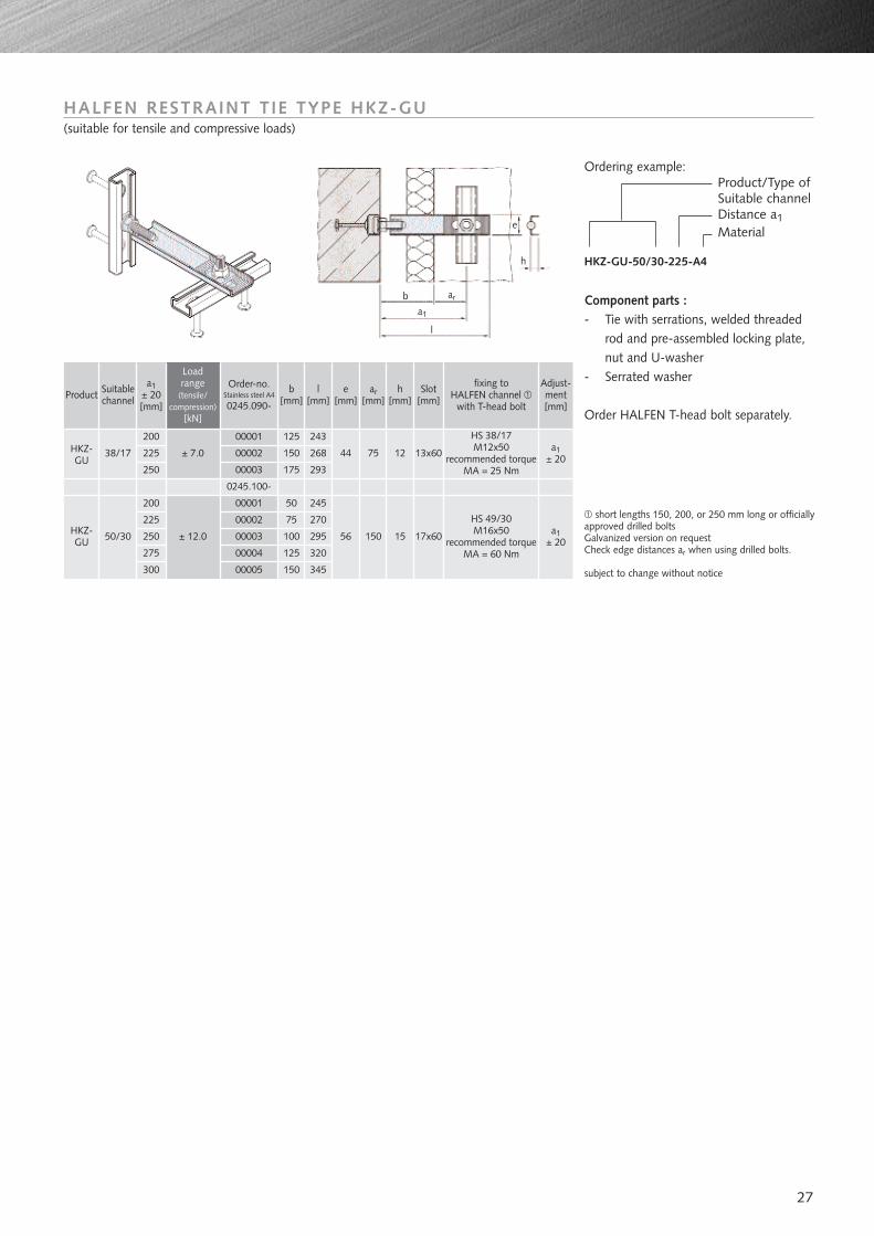
HALFEN RESTRAINT TIE TYPE HKZ-GU(suitable for tensile and compressive loads)
Ordering example:Product/Type ofSuitable channelDistance a1Material
HKZ-GU-50/30-225-A4
Component parts :- Tie with serrations, welded threaded
rod and pre-assembled locking plate,nut and U-washer
- Serrated washer
Order HALFEN T-head bolt separately.
short lengths 150, 200, or 250 mm long or officiallyapproved drilled boltsGalvanized version on requestCheck edge distances ar when using drilled bolts.
subject to change without notice
HKZ-GU
HKZ-GU
200
225
250
200
225
250
275
± 7.0
± 12.0
125 243
44 75 13x60
HS 38/17M12x50
recommended torqueMA = 25 Nm
a1± 20
a1± 20[mm]
Load range
(tensile/compression)
[kN]
b[mm]
e[mm]
Slot[mm]
Adjust-ment[mm]
l[mm]
ar[mm]
fixing to HALFEN channel
with T-head bolt
150 268
175 293
50 245
56 150 17x60
HS 49/30M16x50
recommended torqueMA = 60 Nm
a1± 20
75 270
100 295
125 320
Product h[mm]
12
15
300 150 345
b
e
h
l
a1
ar
Order-no.Stainless steel A4
0245.090-
00001
00002
00003
00001
00002
00003
00004
00005
Suitablechannel
38/17
50/30
0245.100-
28
L
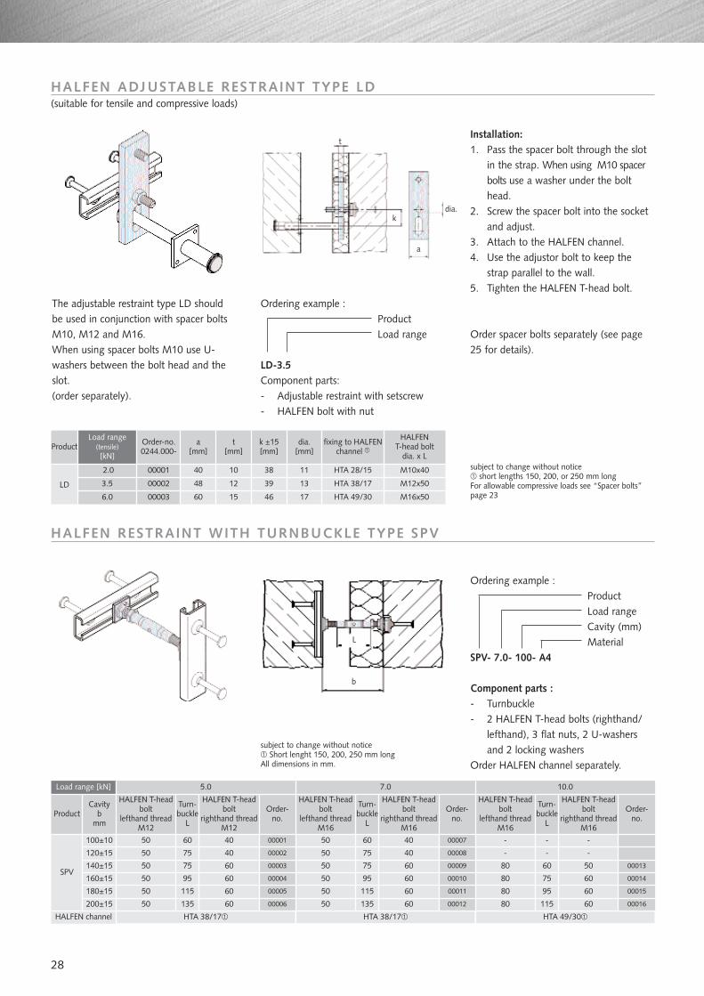
Ordering example :ProductLoad range
LD-3.5Component parts:- Adjustable restraint with setscrew- HALFEN bolt with nut
Ordering example :ProductLoad rangeCavity (mm)Material
SPV- 7.0- 100- A4
Component parts :- Turnbuckle- 2 HALFEN T-head bolts (righthand/
lefthand), 3 flat nuts, 2 U-washersand 2 locking washers
Order HALFEN channel separately.
subject to change without notice short lengths 150, 200, or 250 mm long
For allowable compressive loads see “Spacer bolts”page 23
HALFEN ADJUSTABLE RESTRAINT TYPE LD(suitable for tensile and compressive loads)
HALFEN RESTRAINT WITH TURNBUCKLE TYPE SPV
LD
2.0 40 10 38 11 HTA 28/15
Load range (tensile)[kN]
a[mm]
k ±15[mm]
HALFEN T-head bolt
dia. x L
t[mm]
dia.[mm]
fixing to HALFENchannel
48 12
60 15
Product
6.0 HTA 49/30
39 13
M10x40
M12x50HTA 38/17
M16x501746
3.5
The adjustable restraint type LD shouldbe used in conjunction with spacer boltsM10, M12 and M16.When using spacer bolts M10 use U-washers between the bolt head and theslot. (order separately).
Installation:1. Pass the spacer bolt through the slot
in the strap. When using M10 spacerbolts use a washer under the bolthead.
2. Screw the spacer bolt into the socketand adjust.
3. Attach to the HALFEN channel.4. Use the adjustor bolt to keep the
strap parallel to the wall.5. Tighten the HALFEN T-head bolt.
5.0
HALFEN T-headbolt
lefthand threadM12
Turn-buckle
L
HALFEN T-headbolt
righthand threadM12
Turn-buckle
L
Turn-buckle
L
HALFEN T-headbolt
righthand threadM16
100±10
120±15
140±15
160±15
180±15
200±15
HALFEN channel
Load range [kN] 7.0 10.0
ProductCavity
bmm
HALFEN T-headbolt
lefthand threadM16
HALFEN T-headbolt
lefthand threadM16
HALFEN T-headbolt
righthand threadM16
SPV
135
HTA 38/17 HTA 38/17 HTA 49/30
50
50
50
50
50
50
60
75
75
95
115
40
40
60
60
60
60
50
50
50
50
50
50
60
75
75
95
115
135
40
40
60
60
60
60
-
-
80
80
80
80
-
-
60
75
95
115
-
-
50
60
60
60
subject to change without noticeShort lenght 150, 200, 250 mm long
All dimensions in mm.
t
dia.
a
k
Order-no.0244.000-
00001
00002
00003
Order spacer bolts separately (see page25 for details).
Order-no.
Order-no.
Order-no.
00001
00002
00003
00004
00005
00006
00008
00009
00010
00011
00012
00013
00014
00015
00016
00007
b
29
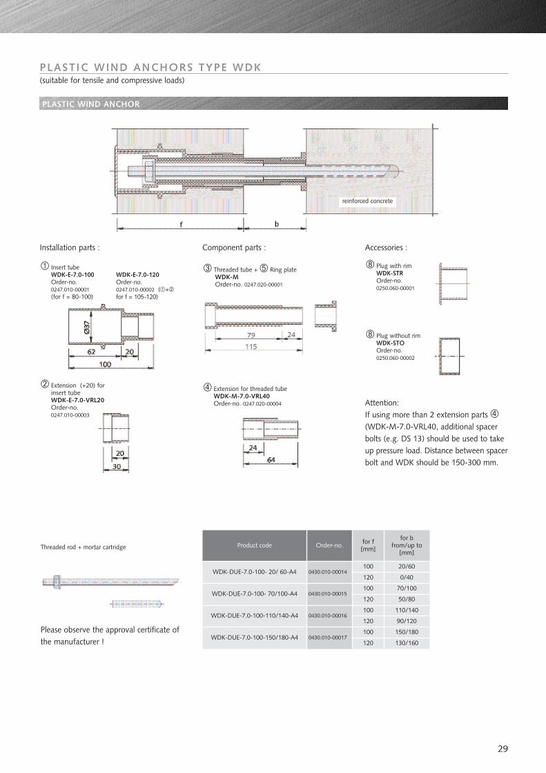
PLASTIC WIND ANCHORS TYPE WDK(suitable for tensile and compressive loads)
Plug with rimWDK-STROrder-no.0250.060-00001
Plug without rimWDK-STOOrder-no.0250.060-00002
PLASTIC WIND ANCHOR
Attention: If using more than 2 extension parts (WDK-M-7.0-VRL40, additional spacerbolts (e.g. DS 13) should be used to takeup pressure load. Distance between spacerbolt and WDK should be 150-300 mm.
Threaded rod + mortar cartridge
Please observe the approval certificate ofthe manufacturer !
Order-no. for f[mm]
for bfrom/up to
[mm]
0430.010-00014100 20/60
120
100
120
100
120
0/40
70/100
50/80
110/140
0430.010-00015
0430.010-00016
0430.010-00017120
100 150/180
130/160
90/120
Product code
WDK-DUE-7.0-100- 20/ 60-A4
WDK-DUE-7.0-100- 70/100-A4
WDK-DUE-7.0-100-110/140-A4
WDK-DUE-7.0-100-150/180-A4
Installation parts : Component parts : Accessories :
reinforced concrete
Insert tubeWDK-E-7.0-100Order-no.0247.010-00001(for f = 80-100)
Extension (+20) forinsert tubeWDK-E-7.0-VRL20Order-no.0247.010-00003
Threaded tube + Ring plateWDK-MOrder-no. 0247.020-00001
Extension for threaded tubeWDK-M-7.0-VRL40Order-no. 0247.020-00004
WDK-E-7.0-120Order-no.0247.010-00002 ( +for f = 105-120)
30
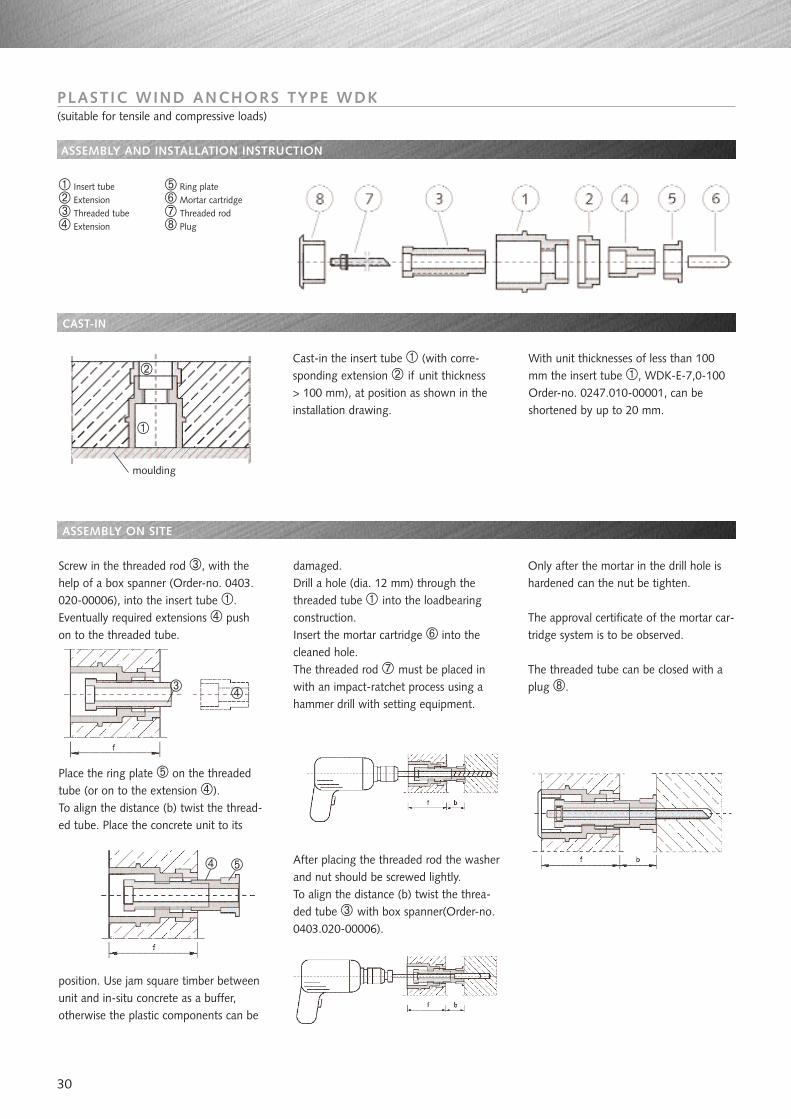
Screw in the threaded rod , with thehelp of a box spanner (Order-no. 0403.020-00006), into the insert tube .Eventually required extensions pushon to the threaded tube.
Place the ring plate on the threadedtube (or on to the extension ). To align the distance (b) twist the thread-ed tube. Place the concrete unit to its
position. Use jam square timber betweenunit and in-situ concrete as a buffer,otherwise the plastic components can be
damaged.Drill a hole (dia. 12 mm) through thethreaded tube into the loadbearingconstruction. Insert the mortar cartridge into thecleaned hole. The threaded rod must be placed inwith an impact-ratchet process using ahammer drill with setting equipment.
After placing the threaded rod the washerand nut should be screwed lightly.To align the distance (b) twist the threa-ded tube with box spanner(Order-no.0403.020-00006).
Only after the mortar in the drill hole ishardened can the nut be tighten.
The approval certificate of the mortar car-tridge system is to be observed.
The threaded tube can be closed with aplug .
PLASTIC WIND ANCHORS TYPE WDK(suitable for tensile and compressive loads)
ASSEMBLY AND INSTALLATION INSTRUCTION
Cast-in the insert tube (with corre-sponding extension if unit thickness> 100 mm), at position as shown in theinstallation drawing.
With unit thicknesses of less than 100mm the insert tube , WDK-E-7,0-100Order-no. 0247.010-00001, can beshortened by up to 20 mm.
Insert tubeExtensionThreaded tubeExtension
Ring plateMortar cartridgeThreaded rodPlug
CAST-IN
ASSEMBLY ON SITE
moulding
31
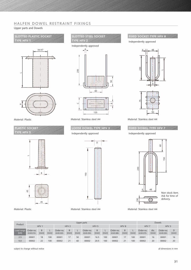
HALFEN DOWEL RESTRAINT F IXINGSUpper parts and Dowels
SLOTTED PLASTIC SOCKET TYPE HFV 1
SLOTTED STEEL SOCKET TYPE HFV 2
Independently approved
FIXED SOCKET TYPE HFV 8
Independently approved
PLASTIC SOCKET TYPE HFV 5
LOOSE DOWEL TYPE HFV 3
Independently approved
FIXED DOWEL TYPE HFV 7
Independently approved
Load range[kN]
2.5
5.0
18
22
100
100
17
21
50
60
16.5
20.5
100
100
17
21
100
100
16
20
B [mm]
L [mm]
B [mm]
B [mm]
B [mm]
D [mm]
L [mm]
L [mm]
L [mm]
Product
subject to change without notice all dimensions in mm
D
B
45
45
150
L
230
60
150
230
486
644/47 6 48
B
50
60
120
230
LB
230
75
L
50BC
HFV 1
Upper parts
Order-no.0249.010-
00001
00002
Order-no.0249.020-
Order-no.0249.050-
Order-no.0249.080-
Order-no.0249.030-
00001
00002
00001
00002
00001
00002
HFV 2 HFV 5 HFV 8 HFV 3
00001
00002
HFV 7
Order-no.0249.070-
dia.[mm]
00001
00002
16
20
Non stock item.Ask for time ofdelivery.
Material: Plastic Material: Stainless steel A4 Material: Stainless steel A4
Material: Plastic Material: Stainless steel A4 Material: Stainless steel A4
Dowels
32
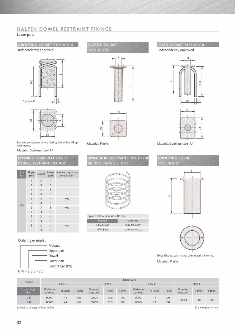
Ordering example :ProductUpper partDowel Lower part Load range (kN)
HFV - 2 3 8 - 2.5
GROUTING SOCKET TYPE HFV 4Independently approved
PLASTIC SOCKETTYPE HFV 5
FIXED SOCKET TYPE HFV 8Independently approved
GROUTING SOCKET TYPE HFV 9
POSSIBLE COMBINATIONS OFDOWEL RESTRAINT FIXINGS
SPIRAL REINFORCEMENT TYPE HFV-Bfits HFV1, HFV5 and HFV9
subject to change without notice all dimensions in mm
HALFEN DOWEL RESTRAINT F IXINGSLower parts
Remove polystyrene before placing dowel then fill upwith mortar.
To be filled up with mortar after dowel is inserted.
L
L
230
75
L
6
B
48
50
6
B
60
Styropor®
200
90 B
Pro-duct
Upperpart Dowel Lower
partIndepend. approved
combination
1
1
1
1
2
2
2
2
5
5
8
8
HFV
3
3
3
3
3
3
3
3
3
3
3
3
4
5
8
9
4
5
8
9
4
9
4
9
-
-
-
-
yes
-
yes
-
-
-
yes
-
B
45
45
L
Load range (kN)
2.5
5.0
44
44
100
10040 100
16.5
20.5
100
100
17
21
100
100
B [mm] L [mm] B [mm]B [mm] B [mm] L [mm]L [mm] L [mm]
ProductHFV 4
Lower parts
Order-no.0249.040-
00001
00001
Order-no.0249.090-
Order-no.0249.050-
Order-no.0249.080-
0000100001
00002
00001
00002
HFV 9HFV 5 HFV 8
Product
HFV-B-WB
HFV-B-A4
Order-no.
0249.100-00001
0249.100-00002
Spiral reinforcement 60 x 80 mm
Material: Stainless steel A4
Material: Plastic Material: Stainless steel A4
Material: Plastic
33
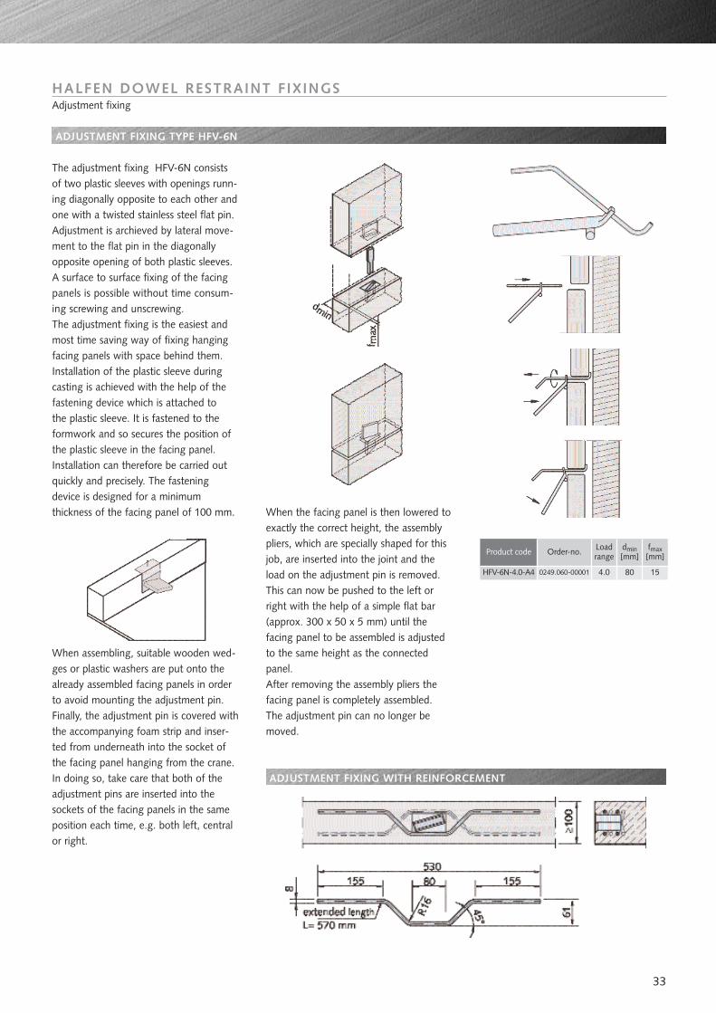
ADJUSTMENT FIXING TYPE HFV-6N
HALFEN DOWEL RESTRAINT F IXINGSAdjustment fixing
The adjustment fixing HFV-6N consistsof two plastic sleeves with openings runn-ing diagonally opposite to each other andone with a twisted stainless steel flat pin.Adjustment is archieved by lateral move-ment to the flat pin in the diagonallyopposite opening of both plastic sleeves.A surface to surface fixing of the facingpanels is possible without time consum-ing screwing and unscrewing. The adjustment fixing is the easiest andmost time saving way of fixing hangingfacing panels with space behind them.Installation of the plastic sleeve duringcasting is achieved with the help of thefastening device which is attached tothe plastic sleeve. It is fastened to theformwork and so secures the position ofthe plastic sleeve in the facing panel.Installation can therefore be carried outquickly and precisely. The fasteningdevice is designed for a minimumthickness of the facing panel of 100 mm.
When assembling, suitable wooden wed-ges or plastic washers are put onto thealready assembled facing panels in orderto avoid mounting the adjustment pin.Finally, the adjustment pin is covered withthe accompanying foam strip and inser-ted from underneath into the socket ofthe facing panel hanging from the crane.In doing so, take care that both of theadjustment pins are inserted into thesockets of the facing panels in the sameposition each time, e.g. both left, centralor right.
When the facing panel is then lowered toexactly the correct height, the assemblypliers, which are specially shaped for thisjob, are inserted into the joint and theload on the adjustment pin is removed.This can now be pushed to the left orright with the help of a simple flat bar(approx. 300 x 50 x 5 mm) until thefacing panel to be assembled is adjustedto the same height as the connectedpanel.After removing the assembly pliers thefacing panel is completely assembled.The adjustment pin can no longer bemoved.
ADJUSTMENT FIXING WITH REINFORCEMENT
Product code Loadrange
dmin[mm]
fmax[mm]
4.0HFV-6N-4.0-A4 80 15
Order-no.
0249.060-00001
34
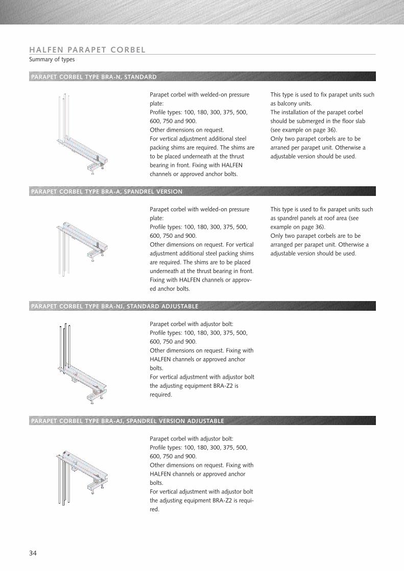
PARAPET CORBEL TYPE BRA-N, STANDARD
PARAPET CORBEL TYPE BRA-A, SPANDREL VERSION
PARAPET CORBEL TYPE BRA-NJ, STANDARD ADJUSTABLE
PARAPET CORBEL TYPE BRA-AJ, SPANDREL VERSION ADJUSTABLE
HALFEN PARAPET CORBELSummary of types
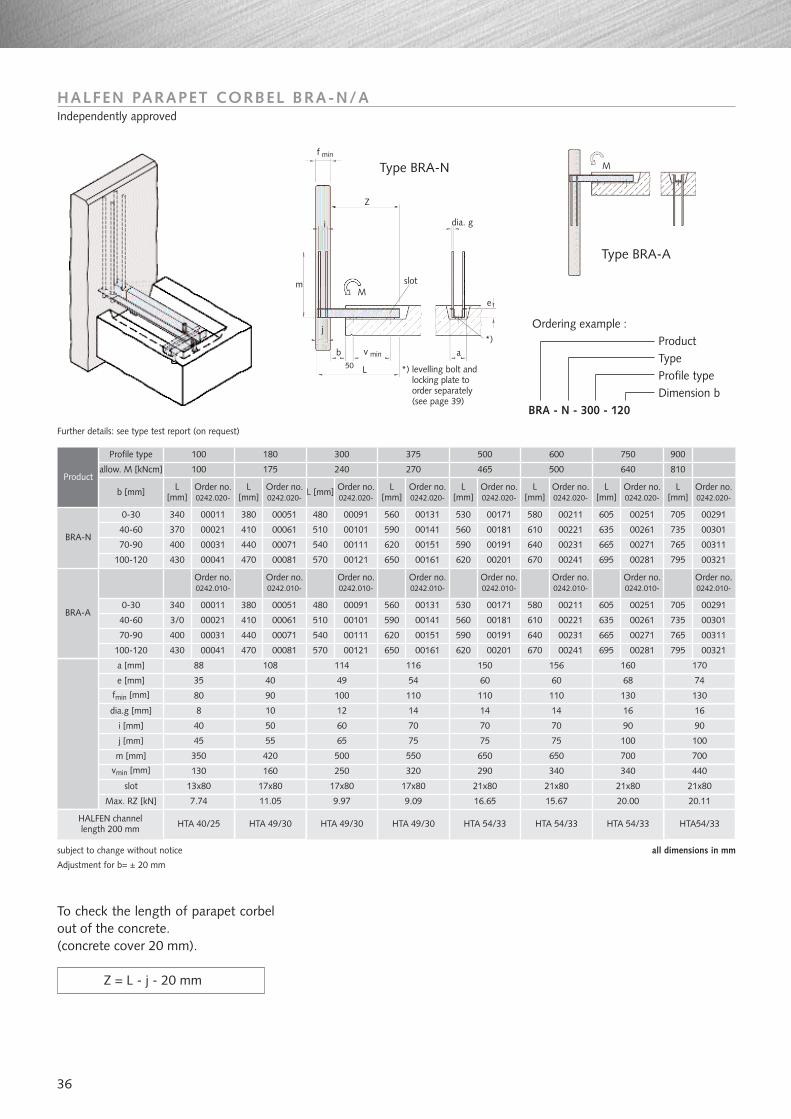
Parapet corbel with welded-on pressureplate:Profile types: 100, 180, 300, 375, 500,600, 750 and 900.Other dimensions on request. For vertical adjustment additional steelpacking shims are required. The shims areto be placed underneath at the thrustbearing in front. Fixing with HALFENchannels or approved anchor bolts.
This type is used to fix parapet units suchas balcony units.The installation of the parapet corbelshould be submerged in the floor slab(see example on page 36). Only two parapet corbels are to bearraned per parapet unit. Otherwise aadjustable version should be used.
Parapet corbel with welded-on pressureplate:Profile types: 100, 180, 300, 375, 500,600, 750 and 900.Other dimensions on request. For verticaladjustment additional steel packing shimsare required. The shims are to be placedunderneath at the thrust bearing in front.Fixing with HALFEN channels or approv-ed anchor bolts.
Parapet corbel with adjustor bolt:Profile types: 100, 180, 300, 375, 500,600, 750 and 900.Other dimensions on request. Fixing withHALFEN channels or approved anchorbolts.For vertical adjustment with adjustor boltthe adjusting equipment BRA-Z2 isrequired.
Parapet corbel with adjustor bolt:Profile types: 100, 180, 300, 375, 500,600, 750 and 900.Other dimensions on request. Fixing withHALFEN channels or approved anchorbolts.For vertical adjustment with adjustor boltthe adjusting equipment BRA-Z2 is requi-red.
This type is used to fix parapet units suchas spandrel panels at roof area (seeexample on page 36).Only two parapet corbels are to bearranged per parapet unit. Otherwise aadjustable version should be used.
35
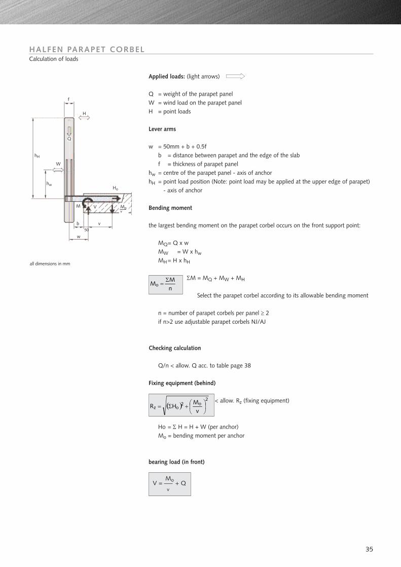
HALFEN PARAPET CORBELCalculation of loads
Applied loads: (light arrows)
Q = weight of the parapet panelW = wind load on the parapet panelH = point loads
Lever arms
w = 50mm + b + 0.5fb = distance between parapet and the edge of the slabf = thickness of parapet panel
hw = centre of the parapet panel - axis of anchorhH = point load position (Note: point load may be applied at the upper edge of parapet)
- axis of anchor
Bending moment
the largest bending moment on the parapet corbel occurs on the front support point:
MQ= Q x wMW = W x hw
MH = H x hH
ΣM = MQ + MW + MH
Select the parapet corbel according to its allowable bending moment
n = number of parapet corbels per panel ≥ 2if n>2 use adjustable parapet corbels NJ/AJ
Checking calculation
Q/n < allow. Q acc. to table page 38
Fixing equipment (behind)
< allow. Rz (fixing equipment)
Ho = Σ H = H + W (per anchor)Mo = bending moment per anchor
bearing load (in front)
( )2
o2oz
vM
HR
+Σ=
nM
MoΣ
=
v
M
W
Q
hw
hH
H
f
V
b
w
Ho
Mov
50
all dimensions in mm
MoV = + Qv
36
Ordering example :ProductTypeProfile typeDimension b
BRA - N - 300 - 120
BRA-N
340
370
400
340
430
88
00011
00021
00031
00011
00041
380 00051 480 00091 00131 530 00171 580
L[mm]
Order no.0242.020-
100
ProductL
[mm] L [mm] L[mm]
L[mm]
Order no.0242.020-
Order no.0242.020-
Order no.0242.020-
Order no.0242.020-
180 500 600
410 00061 510 00101 00141 560 00181 610
440 00071 540 00111 00151 590 00191 640
380 00051 480 00091 00131 530 00171 580
470 00081 570 00121 00161 620 00201 670
108 114 150 156
40 49 60 60
10 12 14 14
50 60 70 70
420 500 650 650
Profile type
b [mm]
0-30
40-60
70-90
0-30
100-120
a [mm]
e [mm]
dia.g [mm]
i [mm]
m [mm]
vmin [mm]
slot
Max. RZ [kN] 11.05
17x80
160 250
17x80
35
8
40
350
130
13x80
7.74
j [mm] 45 55
9.97
65 75
290
21x80
16.65
75
340
21x80
15.67
HALFEN PARAPET CORBEL BRA-N/AIndependently approved
Further details: see type test report (on request)
subject to change without notice all dimensions in mm
mM
dia. g
M
e
av min
L
slot
b
j
50
*)
i
*) levelling bolt andlocking plate toorder separately(see page 39)
Type BRA-N
Type BRA-A
300
100 175 240 465 500allow. M [kNcm]
100-120 430
70-90 400
00041
00031
470
440
00081
00071 00111 00151 00191
375
270
L[mm]
750 900
640 810
L[mm]
L[mm]
00121 00161 00201
00211
00221
00231
00241
00251
00261
00271
00281
00211
00231
00241
00251
00271
00281
570
540
560
590
620
650
560
620
650
620
590
670
640
605
635
665
695
605
665
695
705
735
765
795
705
765
795
Order no.0242.020-
Order no.0242.020-
116 160 170
54 68 74
14 16 16
70 90 90
75 100 100
550 700 700
320 340 440
17x80 21x80 21x80
9.09 20.00 20.11
HALFEN channellength 200 mm HTA 40/25 HTA 49/30 HTA 49/30 HTA 49/30 HTA 54/33 HTA 54/33 HTA 54/33 HTA54/33
Order no.0242.020-
00291
00301
00311
00321
00291
00311
00321
Adjustment for b= ± 20 mm
fmin [mm] 80 90 100 110 110 110 130 130
To check the length of parapet corbelout of the concrete.(concrete cover 20 mm).
Z = L - j - 20 mm
f min
Z
40-60 3/0 00021 410 00061 510 00101 590 00141 560 00181 610 00221 635 00261 735 00301
Order no.0242.010-
Order no.0242.010-
Order no.0242.010-
Order no.0242.010-
Order no.0242.010-
Order no.0242.010-
Order no.0242.010-
Order no.0242.010-
BRA-A
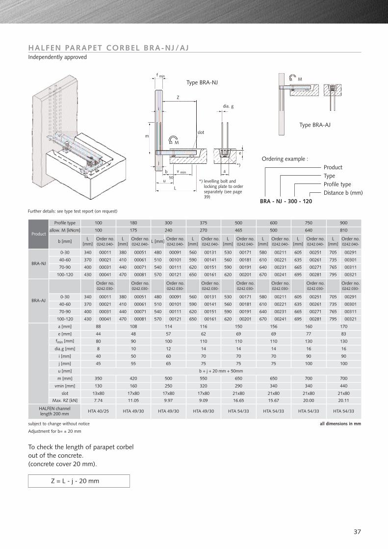
37
HALFEN PARAPET CORBEL BRA-NJ/AJIndependently approved
subject to change without notice all dimensions in mm
Ordering example :ProductTypeProfile typeDistance b (mm)
BRA - NJ - 300 - 120
Further details: see type test report (on request)
dia. g
mM
slot
j
u
L
b a*)
*) levelling bolt andlocking plate to orderseparately (see page39)
e
v min
f min
50
i
Type BRA-NJ
Type BRA-AJ
BRA-NJ
340
370
400
340
370
430
88
00011
00021
00031
00011
00021
00041
380 00051 480 00091 00131 530 00171 580
L[mm]
Order no.0242.040-
100
ProductL
[mm] L [mm] L[mm]
L[mm]
Order no.0242.040-
Order no.0242.040-
Order no.0242.040-
Order no.0242.040-
180 500 600
410 00061 510 00101 00141 560 00181 610
440 00071 540 00111 00151 590 00191 640
380 00051 480 00091 00131 530 00171 580
410 510 00101 00141 560 00181 610
470 00081 570 00121 00161 620 00201 670
108 114 150 156
48 57 69 69
10 12 14 14
50 60 70 70
420 500 650 650
Profile type
b [mm]
0-30
40-60
70-90
0-30
40-60
100-120
a [mm]
e [mm]
dia.g [mm]
i [mm]
m [mm]
vmin [mm]
slot
Max. RZ [kN]
160 250 290 340
17x80 17x80 21x80 21x80
11.05 9.97 16.65 15.67
44
8
40
350
130
13x80
7.74
j [mm] 45 55 65 75 75
300
100 175 240 465 500allow. M [kNcm]
100-120 430 00041 470 00081 570 00121 00161 620 00201 670
375
270
L[mm]
750 900
640 810
L[mm]
L[mm]
00211
00221
00231
00241
00251
00261
00271
00281
00211
00221
00241
00251
00261
00281
560
590
620
650
560
590
650
605
635
665
695
605
635
695
705
735
735
765
795
705
795
Order no.0242.040-
Order no.0242.040-
116 160 170
62 77 83
14 16 16
70 90 90
75 100 100
550 700 700
320 340 440
17x80 21x80 21x80
9.09 20.00 20.11
u [mm] b + j + 20 mm + 50mm
Adjustment for b= ± 20 mm
To check the length of parapet corbelout of the concrete.(concrete cover 20 mm).
Z = L - j - 20 mm
fmin [mm] 80 90 100 110 110 110 130 130
Z
00061
Order no.0242.040-
00291
00301
00311
00321
00291
00301
00321
HALFEN channellength 200 mm HTA 40/25 HTA 49/30 HTA 49/30 HTA 49/30 HTA 54/33 HTA 54/33 HTA 54/33 HTA 54/33
70-90 400 00031 00071 00111 00151 00191 00231 00271 00311765665640590620540440
M
Order no.0242.030-
Order no.0242.030-
Order no.0242.030-
Order no.0242.030-
Order no.0242.030-
Order no.0242.030-
Order no.0242.030-
Order no.0242.030-
BRA-AJ
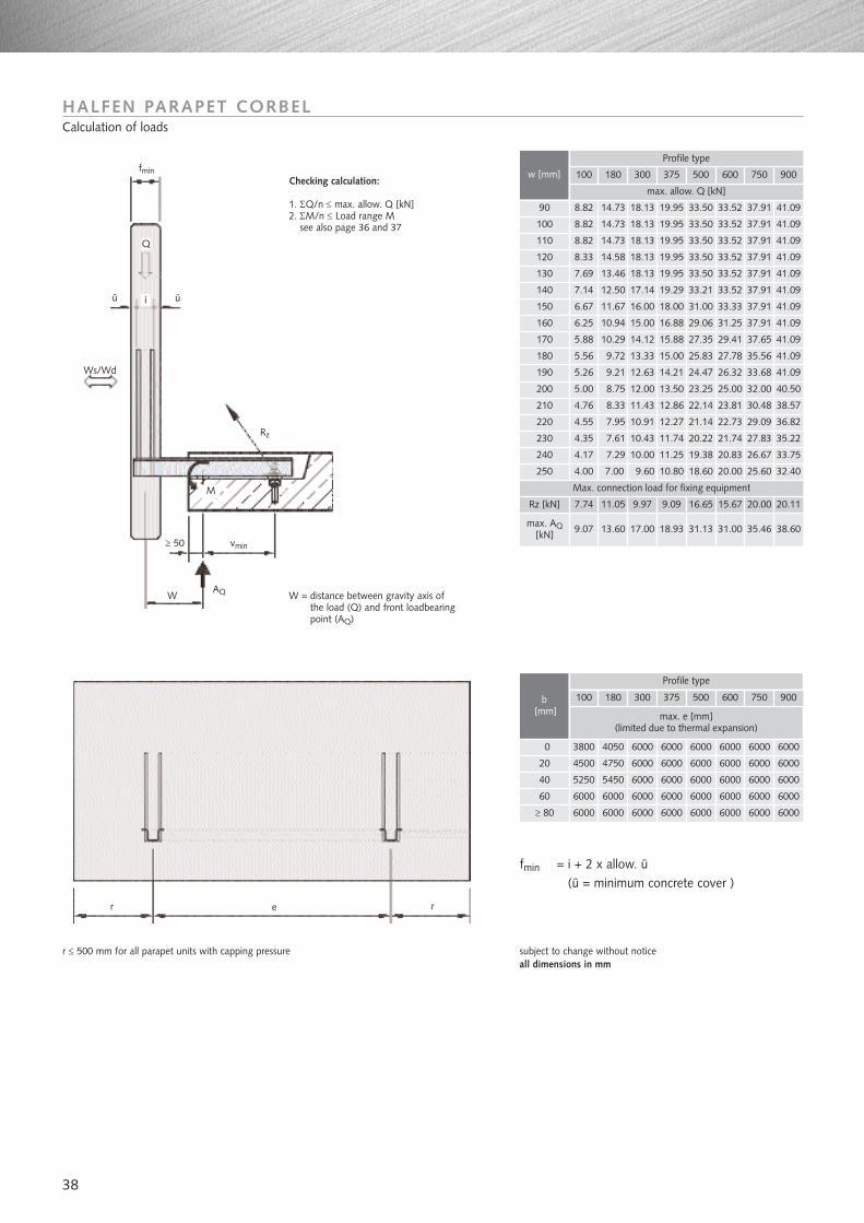
38
HALFEN PARAPET CORBELCalculation of loads
8.82
4.76
4.55
4.35
max. allow. Q [kN]
100 180 300 375 500 900
14.73 18.13 19.95 33.50 41.09
8.33 11.43 12.86 22.14 38.57
7.95 10.91 12.27 21.14 36.82
7.61 10.43 11.74 20.22 35.22
100
210
220
230
110 8.82 14.73 18.13 19.95 33.50 41.09
130 7.69 13.46 18.13 19.95 33.50 41.09
140 7.14 12.50 17.14 19.29 33.21 41.09
150 6.67 11.67 16.00 18.00 31.00 41.09
160 6.25 10.94 15.00 16.88 29.06 41.09
170 5.88 10.29 14.12 15.88 27.35 41.09
180 5.56 9.72 13.33 15.00 25.83 41.09
190 5.26 9.21 12.63 14.21 24.47 41.09
200 5.00 8.75 12.00 13.50 23.25 40.50
90 8.82 14.73 18.13 19.95 33.50 41.09
120 8.33 14.58 18.13 19.95 33.50 41.09
max. AQ[kN]
240
250
Max. connection load for fixing equipment
Rz [kN]
4.17
4.00
7.74
9.07
7.29
7.00
11.05
13.60
10.00
9.60
9.97
17.00
11.25
10.80
9.09
18.93
19.38
18.60
16.65
31.13
33.75
32.40
20.11
38.60
Profile type
w [mm]
3800
5250
4050 6000 6000 6000 6000
max. e [mm](limited due to thermal expansion)
100 180 300 375 500 900
5450 6000 6000 6000 6000
0
40
60 6000 6000 6000 6000 6000 6000
20 4500 4750 6000 6000 6000 6000
≥ 80 6000 6000 6000 6000 6000 6000
b[mm]
Profile type
fmin = i + 2 x allow. ü(ü = minimum concrete cover )
subject to change without notice all dimensions in mm
r ≤ 500 mm for all parapet units with capping pressure
fmin
ü
Q
i
Ws/Wd
Rz
vmin≥ 50
W
r e r
W = distance between gravity axis ofthe load (Q) and front loadbearingpoint (AQ)
Checking calculation:
1. ΣQ/n ≤ max. allow. Q [kN]2. ΣM/n ≤ Load range M
see also page 36 and 37
AQ
M
ü
600 750
33.52 37.91
37.91
37.91
37.91
37.91
37.91
37.91
37.91
33.52
33.52
33.52
33.52
33.52
33.33
31.25
37.6529.41
27.78
26.32
25.00
23.81
22.73
21.74
20.83
20.00 25.60
26.67
27.83
30.48
29.09
32.00
33.68
35.56
600 750
6000
6000
6000
6000
6000
6000
6000
6000
6000
6000
15.67 20.00
31.00 35.46
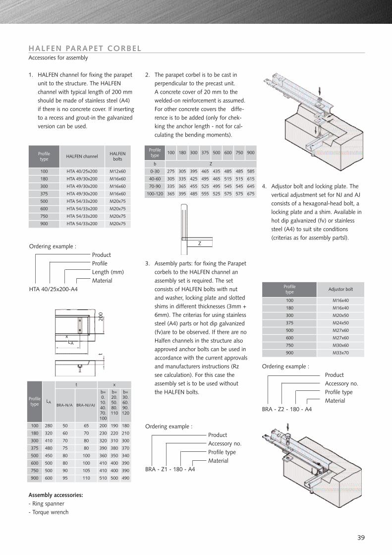
39
HALFEN PARAPET CORBELAccessories for assembly
1. HALFEN channel for fixing the parapetunit to the structure. The HALFENchannel with typical length of 200 mmshould be made of stainless steel (A4)if there is no concrete cover. If insertingto a recess and grout-in the galvanizedversion can be used.
Profiletype HALFEN channel HALFEN
bolts
M16x60
M16x60
M16x60
M20x75
M20x75
M20x75
HTA 49/30x200180
300
375
500
600
750
HTA 49/30x200
HTA 49/30x200
HTA 54/33x200
HTA 54/33x200
HTA 54/33x200
Ordering example :ProductProfileLength (mm)Material
HTA 40/25x200-A4
3. Assembly parts: for fixing the Parapetcorbels to the HALFEN channel anassembly set is required. The setconsists of HALFEN bolts with nutand washer, locking plate and slottedshims in different thicknesses (3mm +6mm). The criterias for using stainlesssteel (A4) parts or hot dip galvanized(fv)are to be observed. If there are noHalfen channels in the structure alsoapproved anchor bolts can be used inaccordance with the current approvalsand manufacturers instructions (Rzsee calculation). For this case theassembly set is to be used withoutthe HALFEN bolts.
Profiletype Adjustor bolt
M16x40
M16x40
M20x50
M24x50
M27x60
M30x60
100
180
300
375
500
750
4. Adjustor bolt and locking plate. Thevertical adjustment set for NJ and AJconsists of a hexagonal-head bolt, alocking plate and a shim. Available inhot dip galvanized (fv) or stainlesssteel (A4) to suit site conditions(criterias as for assembly partsl).
Ordering example :ProductAccessory no.Profile typeMaterial
BRA - Z2 - 180 - A4
Assembly accessories:- Ring spanner- Torque wrench
100 HTA 40/25x200
900 HTA 54/33x200 M20x75
M12x60
Ordering example :ProductAccessory no.Profile typeMaterial
BRA - Z1 - 180 - A4
900 M33x70
600 M27x60
2. The parapet corbel is to be cast inperpendicular to the precast unit.A concrete cover of 20 mm to thewelded-on reinforcement is assumed.For other concrete covers the diffe-rence is to be added (only for chek-king the anchor length - not for cal-culating the bending moments).
Profiletype 100 180 300 375 500 600 750 900
0-30
40-60
70-90
100-120
275
305
335
365
305
335
365
395
395
425
455
485
465
495
525
555
435
465
495
525
485 485 585
615
645
675575575
515
545
515
545
Profiletype
100
180
300
375
500
600
750
900
LA
280
t
50
BRA-N/A BRA-NJ/AJ
x
b=0.10.40.70.100
320
410
480
450
500
500
600
60
70
75
80
80
90
95
65
70
80
80
100
100
105
110
b=20.50.80.110
b=30.60.90.120
200
230
320
390
360
410
410
510
190
220
310
380
350
400
400
500
180
210
300
370
340
390
390
490
b Z
xLA
200
t
Z
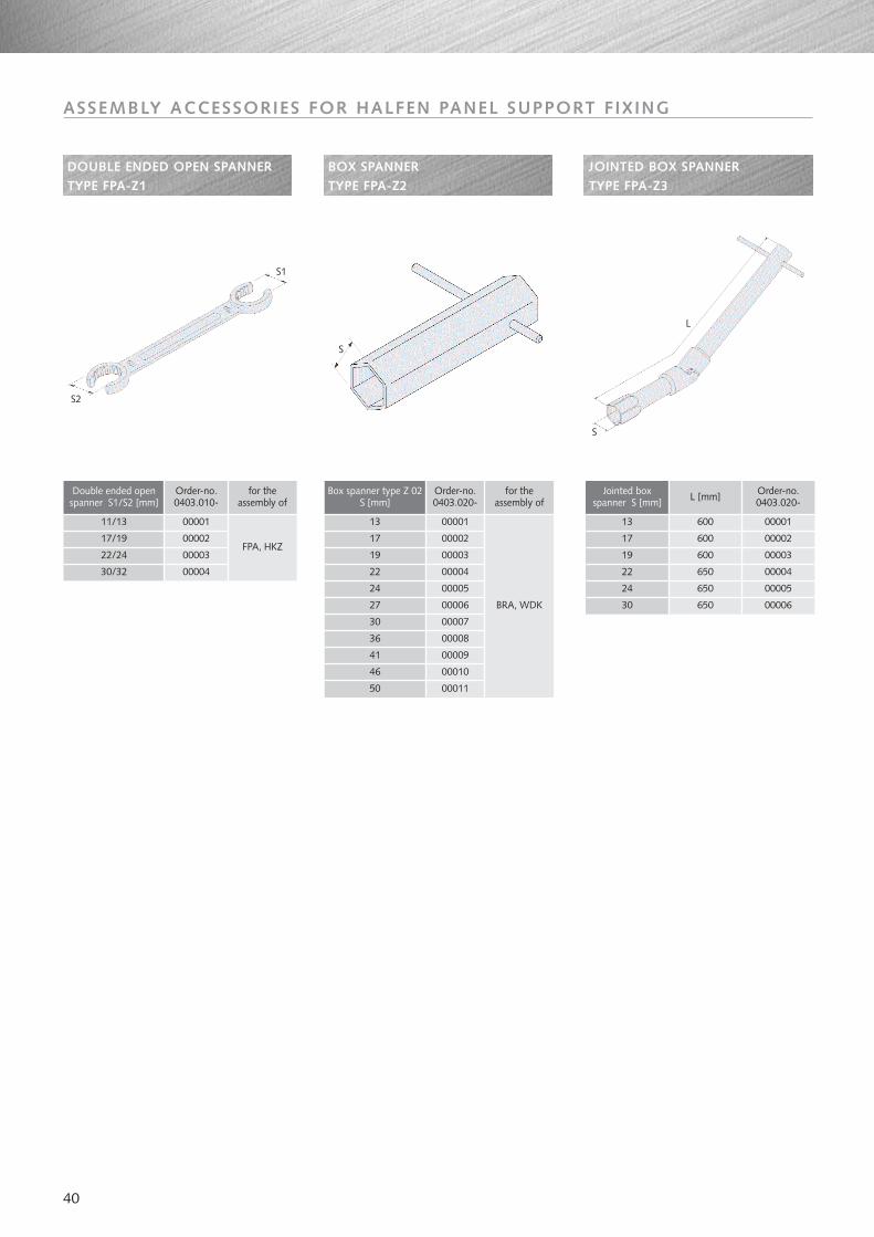
40
DOUBLE ENDED OPEN SPANNERTYPE FPA-Z1
ASSEMBLY ACCESSORIES FOR HALFEN PANEL SUPPORT FIXING
BOX SPANNER TYPE FPA-Z2
JOINTED BOX SPANNER TYPE FPA-Z3
Double ended openspanner S1/S2 [mm]
for the assembly of
FPA, HKZ
11/13
17/19
22/24
30/32
Box spanner type Z 02S [mm]
for the assembly of
BRA, WDK
13
17
19
22
24
30
Jointed box spanner S [mm]
13
17
19
22
24
30
600
600
600
650
650
650
00001
00002
00003
00004
00005
00006
S1
S
S
L
S2
27
36
41
46
50
00001
00002
00003
00004
Order-no.0403.010-
Order-no.0403.020-
00001
00002
00003
00004
00005
00007
00006
00008
00009
00010
00011
L [mm] Order-no.0403.020-
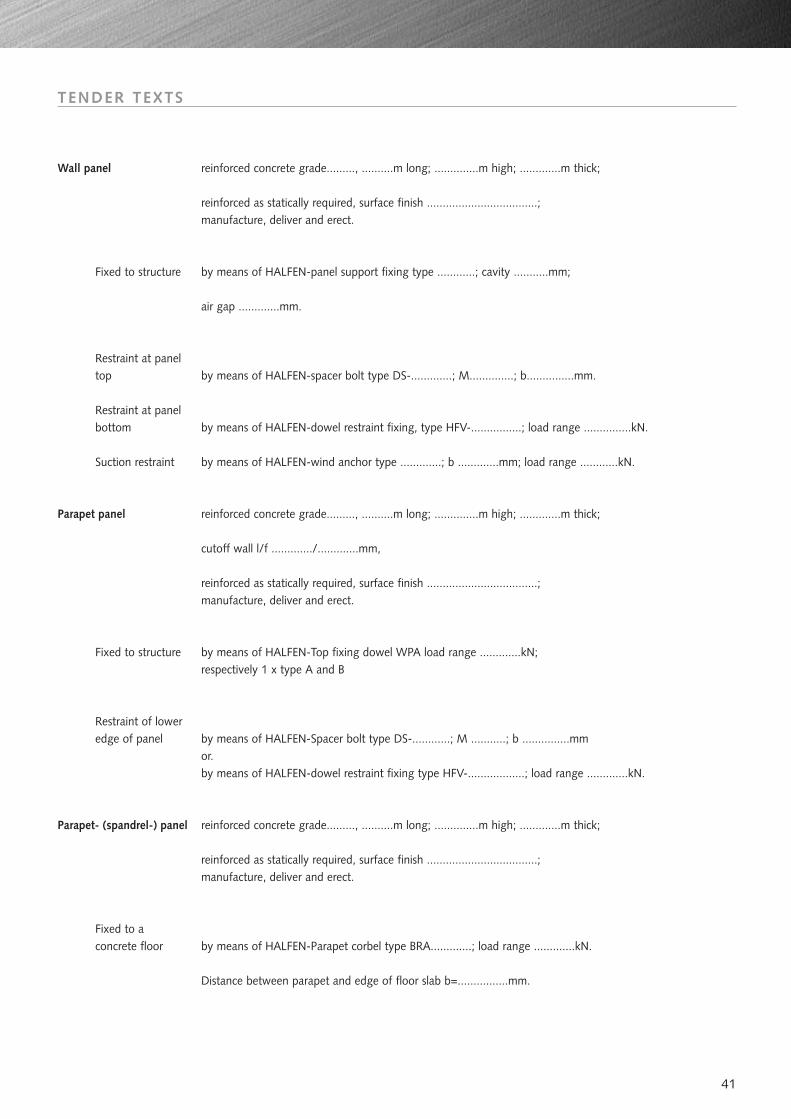
41
TENDER TEXTS
Wall panel reinforced concrete grade........., ..........m long; ..............m high; .............m thick;
reinforced as statically required, surface finish ...................................;manufacture, deliver and erect.
Fixed to structure by means of HALFEN-panel support fixing type ............; cavity ...........mm;
air gap .............mm.
Restraint at panel top by means of HALFEN-spacer bolt type DS-.............; M..............; b...............mm.
Restraint at panel bottom by means of HALFEN-dowel restraint fixing, type HFV-................; load range ...............kN.
Suction restraint by means of HALFEN-wind anchor type .............; b .............mm; load range ............kN.
Parapet panel reinforced concrete grade........., ..........m long; ..............m high; .............m thick;
cutoff wall l/f ............./.............mm,
reinforced as statically required, surface finish ...................................;manufacture, deliver and erect.
Fixed to structure by means of HALFEN-Top fixing dowel WPA load range .............kN; respectively 1 x type A and B
Restraint of lower edge of panel by means of HALFEN-Spacer bolt type DS-............; M ...........; b ...............mm
or.by means of HALFEN-dowel restraint fixing type HFV-..................; load range .............kN.
Parapet- (spandrel-) panel reinforced concrete grade........., ..........m long; ..............m high; .............m thick;
reinforced as statically required, surface finish ...................................;manufacture, deliver and erect.
Fixed to a concrete floor by means of HALFEN-Parapet corbel type BRA.............; load range .............kN.
Distance between parapet and edge of floor slab b=................mm.
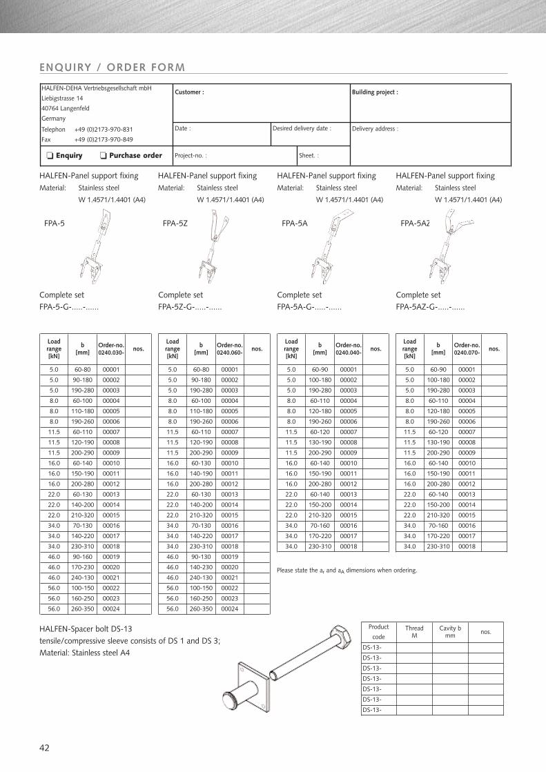
42
ENQUIRY / ORDER FORM
HALFEN-DEHA Vertriebsgesellschaft mbH
Liebigstrasse 14
40764 Langenfeld
Germany
Telephon +49 (0)2173-970-831
Fax +49 (0)2173-970-849
Customer :
Date :
Project-no. :
Building project :
Delivery address :
Enquiry Purchase order
Desired delivery date :
Sheet. :
HALFEN-Panel support fixingMaterial: Stainless steel
W 1.4571/1.4401 (A4)
FPA-5
5.0 60-80 00001
5.0 90-180
190-280
60-100
110-180
190-260
60-110
120-190
200-290
60-140
150-190
200-280
60-130
Order-no.0240.030-
nos.b[mm]
Load range [kN]
5.0
8.0
8.0
8.0
11.5
11.5
11.5
140-200
210-320
70-130
140-220
230-310
90-160
170-230
100-150
160-250
260-350
16.0
16.0
16.0
22.0
22.0
22.0
34.0
34.0
34.0
46.0
46.0
240-13046.0
56.0
56.0
56.0
00002
00003
00004
00005
00006
00007
00008
00009
00010
00011
00012
00013
00014
00015
00016
00017
00018
00019
00020
00021
00022
00023
00024
Complete setFPA-5-G-.....-......
HALFEN-Panel support fixingMaterial: Stainless steel
W 1.4571/1.4401 (A4)
FPA-5Z
Complete setFPA-5Z-G-.....-......
HALFEN-Panel support fixingMaterial: Stainless steel
W 1.4571/1.4401 (A4)
FPA-5A
Complete setFPA-5A-G-.....-......
HALFEN-Panel support fixingMaterial: Stainless steel
W 1.4571/1.4401 (A4)
FPA-5AZ
Complete setFPA-5AZ-G-.....-......
5.0 60-80 00001
5.0 90-180
190-280
60-100
110-180
190-260
60-110
120-190
200-290
60-130
140-190
200-280
60-130
Order-no.0240.060-
nos.b[mm]
Load range [kN]
5.0
8.0
8.0
8.0
11.5
11.5
11.5
140-200
210-320
70-130
140-220
230-310
90-130
140-230
100-150
160-250
260-350
16.0
16.0
16.0
22.0
22.0
22.0
34.0
34.0
34.0
46.0
46.0
240-13046.0
56.0
56.0
56.0
00002
00003
00004
00005
00006
00007
00008
00009
00010
00011
00012
00013
00014
00015
00016
00017
00018
00019
00020
00021
00022
00023
00024
5.0 60-90 00001
5.0 100-180
190-280
60-110
120-180
190-260
60-120
130-190
200-290
60-140
150-190
200-280
60-140
Order-no.0240.040-
nos.b[mm]
Load range[kN]
5.0
8.0
8.0
8.0
11.5
11.5
11.5
150-200
210-320
70-160
170-220
230-310
16.0
16.0
16.0
22.0
22.0
22.0
34.0
34.0
34.0
00002
00003
00004
00005
00006
00007
00008
00009
00010
00011
00012
00013
00014
00015
00016
00017
00018
5.0 60-90 00001
5.0 100-180
190-280
60-110
120-180
190-260
60-120
130-190
200-290
60-140
150-190
200-280
60-140
Order-no.0240.070-
nos.b[mm]
Load range[kN]
5.0
8.0
8.0
8.0
11.5
11.5
11.5
150-200
210-320
70-160
170-220
230-310
16.0
16.0
16.0
22.0
22.0
22.0
34.0
34.0
34.0
00002
00003
00004
00005
00006
00007
00008
00009
00010
00011
00012
00013
00014
00015
00016
00017
00018
Please state the ar and aA dimensions when ordering.
HALFEN-Spacer bolt DS-13tensile/compressive sleeve consists of DS 1 and DS 3; Material: Stainless steel A4
Product
codeThread
MCavity b
mm nos.
DS-13-
DS-13-
DS-13-
DS-13-
DS-13-
DS-13-
DS-13-

43
INTERNET
www.halfen-deha.com •Products •Catalogues •News •Download •Contact •Practice •About HALFEN-DEHA
NOTES REGARDING THIS CATALOGUE:
Technical and design changes reservedThe information in this publication is based on state-of-the-art technology at the time of publication. We reserve the right to maketechnical and design changes at any time. HALFEN-DEHA shall not accept liability for the accuracy of the information in this publicationor for any printing errors.
HALFEN-DEHA is represented in more than 35 countries worldwide. Please contact our Export ServiceCenter, if you wish to receiveinformation about the HALFEN-DEHA foreign representatives.
HALFEN-DEHA WORLDWIDE
HALFEN-DEHAVertriebsgesellschaft mbH-Export ServiceCenter-Liebigstr. 14D-40764 LangenfeldGERMANY
Please contact the Export ServiceCenter for:
Northern Europe Phone: +49 (0) 2173-970-842Fax: +49 (0) 2173-970-850
Eastern Europe Phone:
Middle Europe Phone: +49 (0) 2173-970-193Fax: +49 (0) 2173-970-849
Southern Europe Phone: +49 (0) 2173-970-839Fax: +49 (0) 2173-970-850
Asia / Australia Phone: +49 (0) 2173-970-842Fax: +49 (0) 2173-970-850
Arab Countries / Africa / Phone:
North America Phone: +49 (0) 2173-970-193Fax: +49 (0) 2173-970-849
+49 (0) 2173-970-834Fax: +49 (0) 2173-970-850
+49 (0) 2173-970-842Fax: +49 (0) 2173-970-850
South America Phone: +49 (0) 2173-970-839Fax: +49 (0) 2173-970-850
Phone:Fax:
e-Mail:Internet:
+49 (0) 2173-970-831+49 (0) 2173-970-849
The HALFEN-DEHA Quality Management System is certified for the locations in Gemany and Switzerland according to, Certificate No. QS-281 HH.DIN EN ISO 9001
FE-030-03/04
0.00
003
/04
© 2
004
HA
LFEN
-DEH
A V
ertr
iebs
gese
llsch
aft
mbH
,ap
plie
s al
so t
o co
pyin
g in
ext
ract
s
HALFEN-DEHA Vertriebsgesellschaft mbH · Liebigstraße 14 · 40764 Langenfeld · GERMANYTelefon: + 49 (0) 2173-970-0 · Telefax: + 49 (0) 2173-970-123 · www.halfen-deha.com