Embed Size (px)
Citation preview

HALFEN HS INST_HS 01/18
Assembly Instructions • Montageanleitung • Notice d‘utilisation • Montážní návod • Monteringsanvisningar • Instrukcja montażu • Montagehandleiding
Halfen T-Bolts
D
Śruby młotkowe
Halfenbouten
CZ
SE Halfenskruvar
PL
Šrouby Halfen
NL
Boulons HalfenF
Halfenschrauben
GB
Deu
tsch
Sven
ska
Engl
ish
Fran
çais
Ned
erla
nds
Pols
kiČ
esky
2 © 2018 HALFEN · INST_HS 01/18 · www.halfen.com
HALFEN HS
HS
-KF
1
90°
2
3
HTA 50/30
5
4
A B

Deu
tsch
Pols
kiEn
glis
hFr
ança
isČ
esky
Sven
ska
Ned
erla
nds
H 4.6HALFENFA-70
3© 2018 HALFEN · INST_HS 01/18 · www.halfen.com
HALFEN HS
HTA 38/17
HS
HS 72/48HTA 72/48; HM 72/48
HTA 72/49
HS 50/30
HTA 55/42; HM 55/42
HTA 52/34; HM 52/34
HTA 54/33
HTA 50/30; HTA 50/30 P; HM 50/30
HTA 49/30; HM 49/30
HM 50/40; HL 50/40
HM 486
HS 40/22
HTA 40/22; HTA 40/22 P; HM 40/22
HTA 40/25; HM 40/25
HM 422
HS 41/41
HM 41/41; HL 41/41; HLL 41/41
HM 41/62; HL 41/62
HM 41/83; HL 41/83
HM 41/22; HL 41/22; HLL 41/22
HS 38/17
HTA 38/17; HM 38/17
HM 36/36; HL 36/36
(HZM 38/23); (HZA 38/23)
HS 28/15
HTA 28/15; HM 28/15; HL 28/15
HM 28/28; HL 28/28
HM 26/26; HL 26/26
(HZM 29/20); (HZA 29/20)
HS 20/12 HM 20/12; HL 20/12
H 4.6HALFEN8.8
H 4.6HALFENA4-50
H 4.6HALFEN4.6
H 4.6HALFENA2-50
H 4.6HALFENA - 02 7
H 4.6HALFENA4-70
Combination bolt - channel • Zuordnung Schraube - Schiene • Combinaison boulon - rail • Navržení šroubu pro profi l • Kombinationsskruv – skena • Przyporządkowanie śrub do szyn • Combinatie bout – rail
Identifi cation - steel grade and property class Kennzeichnung Material und Festigkeitsklassen Identifi cation du matériau et classe de résistance Označení materiálu a třídy pevnosti Identifi ering - hållfasthetsklass och skenstorlek Oznaczenie materiału i klasy wytrzymałości Markering – materiaal en sterkteklasse
H 4.6HALFENHCR-50

Deu
tsch
Sven
ska
Engl
ish
Fran
çais
Ned
erla
nds
Pols
kiČ
esky
4 © 2018 HALFEN · INST_HS 01/18 · www.halfen.com
HALFEN HS
Installation torque • Anzugsmomente • Couples de serrage • Utahovací momenty • Åtdragningsmoment •
Moment dokręcenia • Aandraaimoment
A
A
BSteel to concrete • Stahl - Beton Kontakt • Contact acier - béton •Styk ocel - beton • Stål - betong • stal - beton • Staal - beton
Steel to steel • Stahl - Stahl Kontakt • Contact acier - acier Styk ocel - ocel • Stål - stål • stal - stal • Staal - staal
Variants •Einbauvarianten • Types de montage • Varianty montáže • Varianter • Warianty mocowania • Montagevarianten
B
B
A
Flush to concrete surface • Bündig zur Beton-oberfl äche • Affl eurant le béton et le rail • V jedné rovině s povrchem betonu • Plan passning i förhållande till betongytan • W licu płaszczyzny betonu • Gelijk met betonoppervlak

Deu
tsch
Pols
kiEn
glis
hFr
ança
isČ
esky
Sven
ska
Ned
erla
nds
5© 2018 HALFEN · INST_HS 01/18 · www.halfen.com
HALFEN HS
Nm
Tinst [Nm]
M6 M8 M10 M12 M16 M20 M24 M27 M30
ASteel to concrete
Stahl - Beton - Kontakt
Contact acier - béton
Styk ocel - betonStål - betongstal - betonStaal - beton
4.68.85070
28/15 3 8 13 15 - - - - -
38/17 - - 15 25 40 - - - -
40/2240/22 P40/25
- - 15 25 45 - - - -
50/3050/30 P49/30
- - 15 25 60 75 - - -
52/34 54/33 - - 15 25 60 120 - - -
55/42 - - 15 25 60 120 200 - -
72/48 72/49 - - - - - 120 200 300 380
B
Steel to steelStahl - Stahl -
KontaktContact
acier - acierStyk ocel - ocel
Stål - stålstal - stal
Staal - staal
4.6
all profi lesalle Profi le
tous les profi lsvšechny profi ly
alla profi lerwszystkie profi le
alle profi elen
3 8 15 25 65 130 230 340 460
8.8 - 20 40 70 180 360 620 900 1200
50 - 8 15 25 60 120 200 300 400
70 - 15 30 50 130 250 440 650 850

Deu
tsch
Sven
ska
Engl
ish
Fran
çais
Ned
erla
nds
Pols
kiČ
esky
6 © 2018 HALFEN · INST_HS 01/18 · www.halfen.com
HALFEN HS
Note: Only use HALFEN Bolts in combination with the hexagon-nuts which are supplied together with the bolts.
HALFEN Bolts
Notch marking: HALFEN Bolts are marked with notches at the shaft end, fi rst to identify the bolt (HS-bolts have one notch) and second to verify proper installation. After tightening the bolt, the notch must be perpendicular to the longitudinal channel axis.
Identifi cation: Property classes and steel grades are embossed into the bolt head.
Combination bolt - channel: Selection by table or according to the planning documentation.
GB
-KF
1
90°
2
3
4
A B
Note: The T-head bolts used for HALFEN Channels must display the manufacturers marking ”H” or ”HALFEN”. The use of any other bolts is not admissible.
Stainless steel defi nition:A4: Corrosion category III acc. to Z-30.3-6, or acc. to EN 1993-1-4: 2006, table A.1, row 3 (1.4362, 1.4401, 1.4571…).A2: Corrosion category II acc. to Z-30.3-6, or acc. to EN 1993-1-4: 2006, table A.1, row 2 (1.4301, 1.4311, 1.4307…).HCR: Corrosion category IV and V acc. to Z-30.3-6, or acc. to EN 1993-1-4: 2006 (1.4529....)
1 Remove foam fi ller (code KF) from channel.
2 Insert the HALFEN Bolts into the channel slot. Turn 90° clockwise to lock the HALFEN Bolt in position. (Check whether the notch is perpendicular to the channel longitudinal axis)
Shimming in case of recessed cast-in channel: If the face of the channel is recessed from the concrete surface (e.g. due to insuffi cient fi xing to the formwork), then shims must be used between the face of the channel and the back of the compo-nent to create a fl ush surface. Note: the admissible bending moment of the HALFEN Bolt must not be exceeded.
Shimming for stand-off assembly:Washers type US or VUS should always be used under the nut, in particular, when tightening the hex nut directly against the channel face. Use lockwashers type SIC to prevent HALFEN Bolts from loosening.
3 Position of the bolts: installation of HALFEN Bolts in the excess length of the channels is not allowed.
4 Always use the specifi ed installation torque Tinst for your construction. The installation torques depend on bolt type, bolt size, channel type and assembly variant. Refer to the planning documentation or engineer´s specifi cation. The installation torques are shown in the provided tables.
Assembly variants: A Steel to concrete B Steel to steel
Sequence of assembly

Deu
tsch
Pols
kiEn
glis
hFr
ança
isČ
esky
Sven
ska
Ned
erla
nds
7© 2018 HALFEN · INST_HS 01/18 · www.halfen.com
HALFEN HS
Hinweis: Halfenschrauben immer zusammen mit den passenden mitgelieferten Muttern verwenden.
Halfenschrauben
Markierungsschlitz: Der Markierungsschlitz am Schaftende (HS-Schrauben sind mit einem Schlitz versehen) erleichtert die Erkennung des Schrau-bentyps und dient zur Prüfung der korrekten Montage. Der Schlitz muss nach dem Anziehen der Halfenschraube rechtwink-lig zur Schienenlängsachse ausgerichtet sein.
Identifi kation: Die Stahlsorte und Festigkeitsklasse sind auf dem Schraubenkopf aufgeprägt.
Zuordnung Schraube - Schiene: nach Tabelle oder nach Planungsunterlagen.
D
-KF
1
90°
2
Hinweis: Die zum Befestigen an Halfenschienen verwendeten Schrauben müssen mit dem Herstellerkennzeichen ”H” oder ”HALFEN” versehen sein. Die Verwendung anderer Schrauben ist nicht zulässig.
Edelstahlwerkstoff e:A4: Stahl der Korrosionswiderstandsklasse III gemäß Z-30.3-6, bzw. nach EN 1993-1-4: 2006, Tabelle A.1, Zeile 3, (Werkstoff 1.4362, 1.4401, 1.4571…).A2: Stahl der Korrosionswiderstandsklasse II gemäß Z-30.3-6, bzw. nach EN 1993-1-4: 2006, Tabelle A.1, Zeile 2, (Werkstoff 1.4301, 1.4311, 1.4307…).HCR: Stahl der Korroosionswiderstandsklasse IV und V gemäß Z-30.3-6, bzw. nach EN 1993-1-4: 2006, (Werkstoff 1.4529...).
1 Entfernen der Kombi-Streifenfüllung (KF) aus der Halfenschiene nach dem Ausschalen: Streifen von Hand herausziehen und gleichzeitig mit Hilfswerk-zeug, z.B. Schraubendreher heraushebeln.
2 Halfenschrauben in den Schienenschlitz einsetzen. Nach 90° Drehung im Uhrzeigersinn klemmt sich die Halfenschraube in die Schiene (Kontrolle der Lage der Schraube mittels Markierungsschlitz).
Bei zurückliegenden Halfenschienen:Hier muss (z.B. durch ungenaue Befestigung der Schiene an der Scha-lung) der Zwischenraum mit geeigneten Unterlegscheiben unterfüttert werden. Das zulässige Biegemoment der Halfenschraube darf dabei nicht überschritten werden!
Unterlegscheiben bei Abstandsmontage:Zum Befestigen der Mutter unmittelbar vor dem Profi lschlitz ist stets eine Unterlegscheibe Typ VUS oder US zu verwenden. Sicherungscheiben Typ SIC gewährleisten eine zusätzliche Sicherheit gegen das Zurückdrehen der Schraube.
5 After tightening the nut, check whether the T-bolt is properly installed. If the notch is not perpendicular to the longitudinal channel axis, the T-bolt must be completely loosened, re-aligned and re-tightened. Finally re-check the orientation of the notch is now correct.HTA 50/30
5
Montageablauf
Installation torque values apply only to bolts in delivery condition (unlubricated).

Deu
tsch
Sven
ska
Engl
ish
Fran
çais
Ned
erla
nds
Pols
kiČ
esky
8 © 2018 HALFEN · INST_HS 01/18 · www.halfen.com
HALFEN HS
3
4
A B
3 Ausrichten der Halfenschraube: An den Schienenenden darf im Bereich der Endüberstände keine Schraube installiert werden.
4 Das richtige Anzugsmoment Tinst ist zu beachten. Die Anzugsmomente sind abhängig von Schraubentyp, Schraubengröße, Schienentyp und Einbauvari-ante.Entnehmen Sie diese Informationen bitte Ihren Planungsunterlagen oder fragen Sie den Statiker. Die Anzugsmomente sind in den abgebildeten Ta-bellen angegeben.
Einbauvarianten: A Stahl - Beton Kontakt B Stahl - Stahl Kontakt
5 Nach dem Einbau: Richtigen Sitz der Schrauben am Markierungsschlitz des Schraubenschaftes überprüfen. Der Schlitz muss quer zur Schienenlängsrich-tung stehen. Wenn der Schlitz nicht quer zur Schienenlängsrichtung steht, muss die Schraube vollständig gelöst, erneut eingeführt und angezogen werden.
Die Anzugsmomente gelten nur für Halfenschrauben im ungeschmierten Auslieferungszustand.
HTA 50/30
5
Remarque: Toujours utiliser les boulons Halfen avec les écrous appro-priés, livrés avec.
Boulons Halfen
Repère: Le repère à l‘extrémité du fi letage (les boulons HS sont pourvus d‘une fente) facilite l‘identifi cation du type de boulon et sert à vérifi er si le montage est correct. Le repère après serrage du boulon Halfen doit être perpendiculaire à l‘axe du rail.
Identifi cation: Le type d‘acier et la classe de résistance sont marqués sur la tête de boulon.
Combinaison boulon – rail: Selon tableau ou documentation.
F
Remarque: les boulons utilisés pour la fi xation aux rails Halfen doivent être pourvus de la marque du fabricant „H“ ou „HALFEN“. L‘emploi d‘autres boulons n‘est pas autorisé.
Aciers inoxydables:A4: Acier avec classe de résistance à la corrosion III selon Z-30.3-6, resp. EN 1993-1-4: 2006, tableau A.1, ligne 3, (matières 1.4362, 1.4401, 1.4571…).A2: Acier avec classe de résistance à la corrosion II selon Z-30.3-6, resp. EN 1993-1-4: 2006, tableau A.1, ligne 2, (matières 1.4301, 1.4311, 1.4307…).HCR: Acier avec classe de résistance à la corrosion IV et V selon Z-30.3-6, resp. EN 1993-1-4: 2006, (matière 1.4529...).

Deu
tsch
Pols
kiEn
glis
hFr
ança
isČ
esky
Sven
ska
Ned
erla
nds
9© 2018 HALFEN · INST_HS 01/18 · www.halfen.com
HALFEN HS
Les couples de serrage sont uniquement valables pour des boulons Halfen livrés en l‘état (non lubrifi é).
-KF
1
90°
2
1 Retirez le bourrage de mousse du rail Halfen après le décoff rage. Bande de mousse Kombi (KF): Retirez la bande à la main et simultanément faire levier avec un outil approprié, p.ex. tournevis.
2 Insérez les boulons Halfen dans la fente du rail. Après une rotation de 90° dans le sens horaire, le boulon Halfen se coince dans le rail (contrôle de la position du boulon par le repère).
Rail Halfen en retrait du béton:Avec des rails Halfen en retrait (p.ex. à cause d‘une fi xation imprécise sur le coff rage) l‘espace doit être compensé par des rondelles appropri-ées. Le moment fl échissant du boulon Halfen ne doit pas être dépassé!
Rondelles pour montage avec espace:Pour la fi xation de l‘écrou juste devant la fente du profi l, il faut toujours utiliser une rondelle de type VUS ou US. Les rondelles de sécurité type SIV off rent une sécurité supplémentaire contre la rotation en arrière du boulon.
3 Positionnement du boulon Halfen: il n‘est pas permis de placer des boulons dans la zone en extrémité des rails.
4 Toujours observer le couple de serrage correct. Les couples de serrage dé-pendent du type de boulon, de la dimension du boulon, du type de rail et de la variante de montage. Pour ces informations, veuillez vous référer à la documentation ou consulter votre l‘ingénieur Les couples de serrage sont indiqués dans le tableau.
Variantes de montage: A Contact acier - béton B Contact acier - acier
5 Après montage: vérifi ez la position correcte des boulons à l‘aide du repère sur l‘extrémité du fi letage. La fente doit être perpendiculaire au rail. Si le repère n‘est pas perpendiculaire à l‘axe du rail, le boulon doit être entière-ment dévissé, réinséré et de nouveau serré.
Séquences du montage
3
4
A B
HTA 50/30
5

Deu
tsch
Sven
ska
Engl
ish
Fran
çais
Ned
erla
nds
Pols
kiČ
esky
10 © 2018 HALFEN · INST_HS 01/18 · www.halfen.com
HALFEN HS
Pozor: Šrouby Halfen vždy používejte s vhodnými maticemi.
Šrouby Halfen
Zářez na konci dříku šroubu (šrouby HS jsou opatřeny zářezem) usnadňuje identifi kaci typu šroubu a slouží ke kontrole správné montáže. Po utažení šroubu musí být zářez orientován kolmo k podélné ose profi lu.
Identifi kace: Druh oceli a třída pevnosti jsou vyraženy na hlavě šroubu
Navržení šroubu k profi lu: Podle tabulky nebo projektových podkladů.
CZ
-KF
1
90°
2
3
4
A B
Pozor: Šrouby používané k upevnění do profi lů Halfen musí být opatřeny značkou výrobce “H” nebo “HALFEN”. Použití jiných šroubů není přípustné.
Nerez materiály:A4: Ocel antikorozní třídy III podle Z-30.3-6, resp. podle EN 1993-1-4: 2006, tabulka A.1, řádek 3, (materiál 1.4362, 1.4401, 1.4571…).A2: Ocel antikorozní třídy II podle Z-30.3-6, resp. podle EN 1993-1-4: 2006, tabulka A.1, řádek 2, (materiál 1.4301, 1.4311, 1.4307…).HCR: Ocel antikorozní třídy IV a V podle Z-30.3-6, resp. podle EN 1993-1-4: 2006, (materiál 1.4529...).
1 Odstranění výplně z profi lu po odbednění. Kombinovaná výplň (KF): vytáhněte pásek rukou a případně vhodným nářa-dím (šroubovákem) odstraňte zbytky.
2 Šrouby Halfen nasaďte do štěrbiny profi lu. Po otočení o 90° ve směru hodinových ručiček šroub zapadne do profi lu (kontrola polohy šroubu podle zářezu na konci dříku).
„Utopené” profi ly Halfen: V případě „utopených“ profi lů Halfen (např. nepřesným upevněním profi lu na bednění) musí být meziprostor vyplněn vhodnými podložkami. Přípustný ohybový moment nesmí být překročen!
Podložky při montáži s distancí:K upevnění matice bezprostředně před šterbinou profi lu vždy použijte podložku typ VUS nebo US. Pojistné podložky typ SIC zaručují dodatečnou bezpečnost proti otočení šroubu zpět.
3 Umístění šroubů Halfen: v oblasti koncových přesahů nesmí být šrouby ins-talovány.
4 Dodržujte správný utahovací moment. Momenty závisí na typu, velikosti šroubu, typu profi lu a variantě montáže. Tyto informace jsou uvedeny v projektové dokumentaci. Případně se dotázejte statika. Utahovací mo-menty naleznete v tabulkách.
Varianty montáže: A Styk ocel - beton B Styk ocel - ocel
Průběh montáže

Deu
tsch
Pols
kiEn
glis
hFr
ança
isČ
esky
Sven
ska
Ned
erla
nds
11© 2018 HALFEN · INST_HS 01/18 · www.halfen.com
HALFEN HS
Obs! Använd alltid Halfenskruvar tillsammans med sexkantsmuttrarna som levereras med skruvarna.
Halfenskruvar
Spårmärkning: Halfenskruvar har spår på den gängade änden för identifi ering av skruven (HS-skruvar har ett spår) och för kontroll av kor-rekt montering. Efter åtdragning av skruven ska spåret vara vinkelrät i förhållande till skenans långsida.
Identifi ering: Hållfasthetsklass och skenstorlek fi nns på skruvhuvudet.
Kombinationsskruv – skena: Fastställs enligt tabellen eller bygghandlingarna.
SE
-KF
1
90°
2
Obs! Halfenskruvar som används med Halfenskenor måste vara tydligt märkta med tillverkarens „H“ eller „HALFEN“. Det är inte tillåtet att använda andra skruvar.
Defi nition av rostfritt stål:A4: Korrosivitetsklass III enligt Z-30.3-6 eller EN 1993-1-4: 2006, tabell A.1, rad 3 (1.4362, 1.4401, 1.4571…).A2: Korrosivitetsklass II enligt Z-30.3-6 eller EN 1993-1-4: 2006, tabell A.1, rad 2 (1.4301, 1.4311, 1.4307…).HCR: Korrosivitetsklass IV och V enligt Z-30.3-6 eller EN 1993-1-4: 2006 (1.4529....)
1 Ta bort skumfyllning -Kombinationsfyllnad (kod KF): Ta tag i ena änden av remsan med handen och dra sedan ut den med hjälp av ett verktyg, t.ex. en skruvmejsel.
2 Sätt i Halfenskruvarna i skenans spår. Efter 90 graders vridning medurs låses Halfenskruven fast på plats. (Kontrollera att spåret är vinkelrät i förhållande till skenans långsida)
Mellanlägg för försänkta, ingjutna skenor:Om skenans yta (t.ex. på grund av otillräcklig förankring i gjutformen) är försänkt i förhållande till betongytan, måste distansbrickor användas mellan skenans yta och komponentens baksida för att skapa en plan yta.Obs: Halfenskruvens högsta tillåtna böjmoment får inte överskridas.
Mellanlägg för montering av distansbrickor:Brickor av typen US eller VUS måste alltid användas före muttern. Detta gäller i synnerhet vid åtdragning av sexkantsmuttern direkt mot skenans yta. Använd SIC-låsbrickor för att förhindra Halfenskruvarna från att skruvas ut.
5 Po montáži: zkontrolujte správné usazení šroubů podle zářezu na dříku šroubu. Zářez musí stát kolmo k podélnému směru profi lu. Pokud není šroub usazen správně, musí být znovu správně umístěn v profi lu a dota-žen.HTA 50/30
5
Montering
Utahovací momenty platí pouze pro šrouby Halfen v nenamaza-
ném stavu.

Deu
tsch
Sven
ska
Engl
ish
Fran
çais
Ned
erla
nds
Pols
kiČ
esky
12 © 2018 HALFEN · INST_HS 01/18 · www.halfen.com
HALFEN HS
3
4
A B
3 Placering: Halfenskruvar får inte monteras för långt ut på skenan.
4 Använd alltid korrekt åtdragningsmoment (Tinst). Åtdragningsmomentet beror på skruvens typ och storlek, typ av skena samt monteringssätt. Den här infor-mationen erhålls från bygghandlingarna eller din tekniker.
Monteringssätt: A Stål - betong B Stål - stål
5 Kontrollera att spåret på Halfenskruven är vinkelrät i förhållande till skenans långsida efter åtdragning av muttern. Om spåret inte är vinkelrät måste skruven lossas helt för att sedan skruvas in och dras åt igen.
Åtdragningsmomentet gäller endast skruvar i nyskick (osmorda).
HTA 50/30
5
Uwaga: Śruby młotkowe stosować zawsze z dostarczanymi, odpowiednimi nakrętkami.
Śruby młotkowe
Oznakowanie w postaci nacięcia: Nacięcie na końcu trzonu śruby (śruby HS posiadają nacięcie) ułatwia rozpoznanie typu śruby i służy do kontroli prawidłowości montażu. Nacięcie, po dociągnięciu śruby młotkowej, musi być ustawione prostopadle do osi podłużnej szyny.
Identyfi kacja: Gatunek stali i klasa wytrzymałości wytłoczone są na łbie śruby.
Przyporządkowanie śrub do szyn: Według tabeli lub projektu
PL
Uwaga: Śruby do mocowania w szynach Halfen muszą być oznaczone znakiem producenta „H“ lub „HALFEN“. Zastosowanie innych śrub jest niedopuszczalne.
Rodzaje materiałów ze stali nierdzewnej:A4: Stal III klasy odporności na korozję według aprobaty Z-30.3-6, lub według EN 1993-1-4: 2006, Tabela A.1, wiersz 3, (materiał 1.4362, 1.4401, 1.4571…).A2: Stal II klasy odporności na korozję według aprobaty Z-30.3-6, lub według EN 1993-1-4: 2006, Tabela A.1, wiersz 2, (materiał 1.4301, 1.4311, 1.4307…).HCR: Stal IV i V klasy odporności na korozję według aprobaty Z-30.3-6, lub według EN 1993-1-4: 2006, (materiał 1.4529...).
Deu
tsch
Pols
kiEn
glis
hFr
ança
isČ
esky
Sven
ska
Ned
erla
nds
13© 2018 HALFEN · INST_HS 01/18 · www.halfen.com
HALFEN HS
Momenty dokręcenia obowiązują tylko dla śrub Halfen w stanie dostawy – śruby nienasmarowane.
-KF
1
90°
2
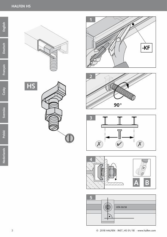
1 Usunięcie wypełnienia piankowego z szyny po rozszalowaniu.Taśma wypełniająca Kombi (KF): Taśmę wyciągać ręcznie i jednocześnie podważać narzędziem, np. śrubokrętem.
2 Śruby młotkowe umieścić w szczelinie szyny. Po obrocie o 90°, zgodnie z kierunkiem ruchu wskazówek zegara, śruba młotkowa zakleszcza się (kontrola położenia śruby przy pomocy nacięcia).
Szyny Halfen nielicujące z płaszczyzną betonu:Jeśli szyna i powierzchnia betonu (np. z powodu niedostatecznego zamocowania do deskowania) nie leżą w jednej płaszczyźnie, należy zastosować właściwe podkładki. Należy zwrócić uwagę, aby nie przekroczyć dopuszczalnego momentu zginającego śruby!
Podkładki przy montażu z odstępem:Do mocowania nakrętki bezpośrednio przy profi lu należy stosować zawsze podkładkę typu VUS lub US. Podkładki typu SIC zabezpieczają śrubę przed odkręceniem.
3 Lokalizacja śrub młotkowych: na końcach szyn, w obszarach za kotwami, śruby nie mogą być instalowane.
4 Należy zwracać uwagę na właściwy moment dokręcenia Tinst. Momenty dokręcenia zależne są od typu śruby, rozmiaru, typu szyny i wariantu wbudowania. Proszę sięgnąć po te informacje do projektu lub zapytać projektanta. Momenty dokręcenia podane są w tabelach.
Warianty mocowania: A Stal - beton B Stal - stal
5 Po montażu: Sprawdzić położenie śrub poprzez kontrolę położenia nacięcia na trzonie śruby. Nacięcie musi być prostopadłe do długości szyny. Jeśli tak nie jest, śrubę należy odkręcić, na nowo wprowadzić i odpowiednio dokręcić.
Montaż
3
4
A B
HTA 50/30
5

Deu
tsch
Sven
ska
Engl
ish
Fran
çais
Ned
erla
nds
Pols
kiČ
esky
14 © 2018 HALFEN · INST_HS 01/18 · www.halfen.com
HALFEN HS
Opmerking: Halfenbouten altijd samen met de meegeleverde moeren gebruiken.
Halfenbouten
Markeringssleuf: De markeringssleuf op het einde van de bout steel (HS-bouten hebben één sleuf) dient ter identifi catie van de bout en ter controle van de juiste montage. De sleuf moet haaks op de langsrichting van de rail staan.
Identifi catie: Staalsoort en sterkteklasse zijn aangegeven op de kop van de bout.
Combinatie bout – rail: volgens tabel of bestek.
NL
-KF
1
90°
2
3
4
A B
Opmerking: Bouten die in combinatie met Halfenrails worden gebruikt, moeten zijn voorzien van het fabrikantkenmerk “H” of “Halfen”. Het toepassen van andere bouten is niet toegestaan.
Roestvaststaal kwaliteit:A4: Staal van corrosieweerstandsklasse III volgens Zulassung Z-30.3-6 of volgens EN 1993-1-4: 2006, tabel A.1, rij 3 (1.4362, 1.4401, 1.4571…).A2: Staal van corrosieweerstandsklasse II volgens Zulassung Z-30.3-6 of volgens EN 1993-1-4: 2006, tabel A.1, rij 2 (1.4301, 1.4311, 1.4307…).HCR: Staal van corrosieweerstandsklasse IV en V volgens Zulassung Z-30.3-6 of volgens EN 1993-1-4: 2006 (1.4529....)
1 Verwijder Combivulling (KF): de strip met de hand en gelijktijdig met gereedschap, bijv. een schroevendraaier, verwijderen.
2 De Halfenbouten in de railopening plaatsen. De bout 90° draaien en daarna de moer vastdraaien (na montage de juiste positie van de Halfenbout middels markeringssleuf controleren).
Sluitringen bij terugliggende Halfenrail:Als door onzorgvuldig instorten de voorkant van de rail enigszins naar achteren ligt, is het aan te raden bij het monteren sluitringen te gebruiken. Het aandraaimoment van de Halfenbout mag daarbij niet worden overschreden!
Sluitringen bij afstandsmontage:Indien de moer direct tegen de rail bevestigd wordt dient een veiligheidssluitplaat type VUS of sluitring type US gebruikt te worden. Door het gebruik van veiligheidsborgplaatjes type SIC wordt het terugdraaien van de bout voorkomen.
3 Positionering van de Halfenbouten: de bouten niet aan de uiteinden van de rail plaatsen.
4 Gebruik altijd het juiste aandraaimoment Tinst. De aandraaimomenten zijn afhankelijk van bouttype, boutdiameter, railtype en montagevariant. Raadpleeg voor deze informatie de gemaakte berekeningen of vraag de constructeur.De aandraaimomenten zijn te vinden in de tabel.
Montagevarianten: A Staal - beton B Staal - staal
Montagevolgorde

Deu
tsch
Pols
kiEn
glis
hFr
ança
isČ
esky
Sven
ska
Ned
erla
nds
15© 2018 HALFEN · INST_HS 01/18 · www.halfen.com
HALFEN HS
5 Na montage: de juiste positie van de Halfenbout controleren. Indien de sleuf niet haaks op de langsrichting van de rail staat, moet de bout volledig worden verwijderd en opnieuw worden geplaatst en aangedraaid.
HTA 50/30
5
De aandraaimomenten gelden alleen voor Halfenbouten die niet voorzien zijn van vet.
© 2
018
HA
LFEN
Gm
bH, G
erm
any
appl
ies
also
to
copy
ing
in e
xtra
cts.
CONTACT HALFEN WORLDWIDE
HALFEN is represented by subsidiaries in the following countries, please contact us:
NOTES REGARDING THIS DOCUMENTTechnical and design changes reserved. The information in this publication is based on state-of-the-art technology at the time of publication. We reserve the right to make technical and design changes at any time. HALFEN GmbH shall not accept liability for the accuracy of the information in this publication or for any printing errors.
The HALFEN GmbH subsidiaries in Germany, France, the Netherlands, Austria, Poland, Switzerland and the Czech Republic are Quality Management certifi ed according to ISO 9001:2015, Certifi cate no. 202384-2016-AQ-GER-DAkkS.
HALFEN is represented with sales offi ces and distributors worldwide.
Please contact us: www.halfen.com
www.dnvgl.com
Austria HALFEN Gesellschaft m.b.H.Leonard-Bernstein-Str. 101220 Wien
Phone: +43 - 1 - 259 6770 E-Mail: offi [email protected]: www.halfen.at
Fax: +43 - 1 - 259 - 6770 99
Belgium /Luxembourg
HALFEN N.V.Borkelstraat 1312900 Schoten
Phone: +32 - 3 - 658 07 20E-Mail: [email protected]: www.halfen.be
Fax: +32 - 3 - 658 15 33
China HALFEN Construction Accessories Distribution Co.Ltd.Room 601 Tower D, Vantone CentreNo.A6 Chao Yang Men Wai StreetChaoyang District Beijing · P.R. China 100020
Phone: +86 - 10 5907 3200E-Mail: [email protected]: www.halfen.cn
Fax: +86 - 10 5907 3218
Czech Republic HALFEN s.r.o.Business Center ŠafránkovaŠafránkova 1238/1155 00 Praha 5
Phone: +420 - 311 - 690 060E-Mail: [email protected]: www.halfen-deha.cz
Fax: +420 - 235 - 314308
France HALFEN S.A.S.18, rue Goubet75019 Paris
Phone: +33 - 1 - 445231 00E-Mail: [email protected]: www.halfen.fr
Fax: +33 - 1 - 445231 52
Germany HALFEN Vertriebsgesellschaft mbHLiebigstr. 14 40764 Langenfeld
Phone: +49 - 2173 - 970 0E-Mail: [email protected]: www.halfen.de
Fax: +49 - 2173-970 225
Italy HALFEN S.r.l. Soc. UnipersonaleVia F.lli Bronzetti N° 2824124 Bergamo
Phone: +39 - 035 - 0760711E-Mail: [email protected]: www.halfen.it
Fax: +39 - 035 - 0760799
Netherlands HALFEN b.v.Oostermaat 37623 CS Borne
Phone: +31 - 74-267 14 49E-Mail: [email protected]: www.halfen.nl
Fax: +31 - 74-2 67 26 59
Norway HALFEN ASPostboks 20804095 Stavanger
Phone: +47 - 51 82 34 00E-Mail: [email protected]: www.halfen.no
Fax: +47 - 51 82 34 01
Poland HALFEN Sp. z o.o.Ul. Obornicka 28760-691 Poznan
Phone: +48 - 61 - 622 14 14E-Mail: [email protected]: www.halfen.pl
Fax: +48 - 61 - 622 14 15
Spain HALFEN SpainPLAKABETON S.L.Polígono Industrial Santa Ana c/ Ignacio Zuloaga 2028522 Rivas-Vaciamadrid
Phone: +34 916 669 181E-Mail: [email protected]: www.halfen.es
Fax: +34 916 669 661
Sweden Halfen ABVädursgatan 5412 50 Göteborg
Phone: +46 - 31 - 98 58 00E-Mail: [email protected]: www.halfen.se
Fax: +46 - 31 - 98 58 01
Switzerland HALFEN Swiss AGHertistrasse 25 8304 Wallisellen
Phone: +41 - 44 - 849 78 78E-Mail: [email protected]: www.halfen.ch
Fax: +41 - 44 - 849 78 79
United Kingdom /Ireland
HALFEN Ltd.A1/A2 Portland CloseHoughton Regis LU5 5AW
Phone: +44 - 1582 - 47 03 00E-Mail: [email protected]: www.halfen.co.uk
Fax: +44 - 1582 - 47 03 04
United States of America
HALFEN USA Inc. PO Box 18687 San Antonio TX 78218
Phone: +1 800.423.91 40E-Mail: [email protected]: www.halfenusa.com
Fax: +1 877.683.4910
For countries not listed HALFEN International
HALFEN International GmbHLiebigstr. 14 40764 Langenfeld / Germany
Phone: +49 - 2173 - 970 - 0 E-Mail: [email protected]: www.halfen.com
Fax: +49 - 2173 - 970 - 849
U -
550
- 01/
18