Embed Size (px)
Citation preview
1
HALE UAV: HALE UAV: AeroVironmentAeroVironment PathfinderPathfinder
Desta Alemayehu
Elizabeth Eaton
Imraan Faruque
Aerodynamic and StabilityAnalysis
Case Study: PlanformOptimization
Photo courtesy NASA Dryden Photo Gallery
2
Pathfinder HistoryPathfinder History
•• Designed and fabricated by Designed and fabricated by AeroVironmentAeroVironment in 1981in 1981•• Determined technology insufficient to support Determined technology insufficient to support mutlimutli--day day
duration flights under solar power and Pathfinder was put into duration flights under solar power and Pathfinder was put into storagestorage
•• In 1993, brought back to flight by Ballistic Missile Defense In 1993, brought back to flight by Ballistic Missile Defense OrganizationOrganization
•• Transferred to NASA in 1994 to support Environmental Transferred to NASA in 1994 to support Environmental Research Aircraft and Sensor Technology (ERAST) programResearch Aircraft and Sensor Technology (ERAST) program
•• ERAST program demonstrated that a high AR, solarERAST program demonstrated that a high AR, solar--powered powered lightweight craft could take off and land at an airport and fly lightweight craft could take off and land at an airport and fly at extremely high altitudes (50at extremely high altitudes (50--80K ft)80K ft)
•• ERAST also determines feasibility of such ERAST also determines feasibility of such UAVsUAVs for carrying for carrying instruments used in scientific studiesinstruments used in scientific studies
Photo courtesy NASA Dryden Photo Gallery
3
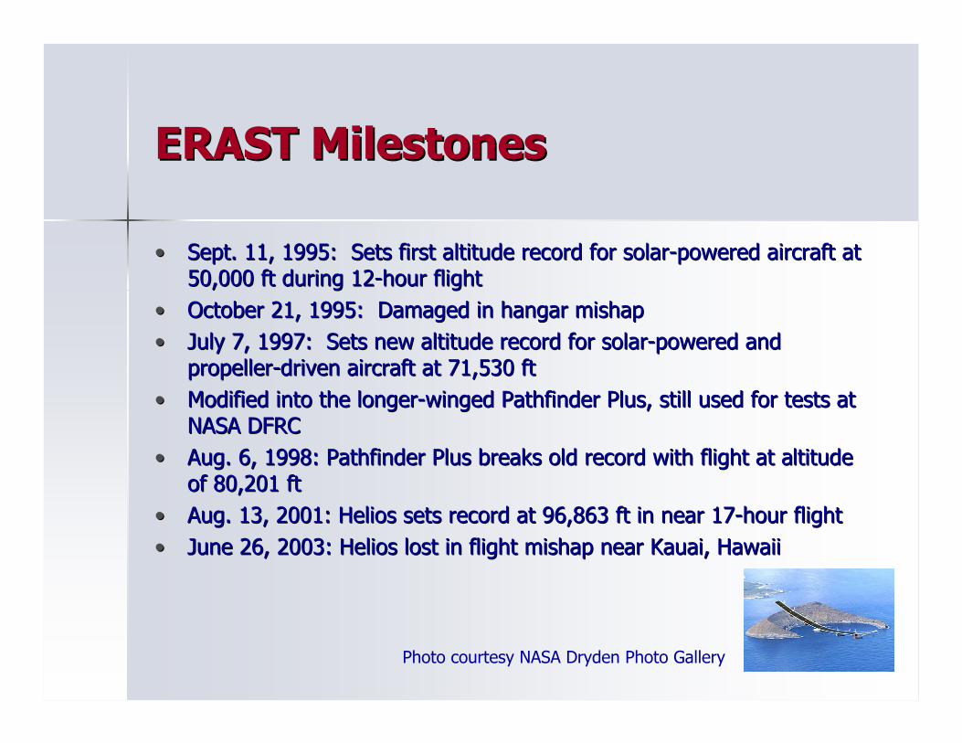
ERAST MilestonesERAST Milestones
•• Sept. 11, 1995: Sets first altitude record for solarSept. 11, 1995: Sets first altitude record for solar--powered aircraft at powered aircraft at 50,000 ft during 1250,000 ft during 12--hour flighthour flight
•• October 21, 1995: Damaged in hangar mishapOctober 21, 1995: Damaged in hangar mishap•• July 7, 1997: Sets new altitude record for solarJuly 7, 1997: Sets new altitude record for solar--powered and powered and
propellerpropeller--driven aircraft at 71,530 ftdriven aircraft at 71,530 ft•• Modified into the longerModified into the longer--winged Pathfinder Plus, still used for tests at winged Pathfinder Plus, still used for tests at
NASA DFRCNASA DFRC•• Aug. 6, 1998: Pathfinder Plus breaks old record with flight at aAug. 6, 1998: Pathfinder Plus breaks old record with flight at altitude ltitude
of 80,201 ftof 80,201 ft•• Aug. 13, 2001: Helios sets record at 96,863 ft in near 17Aug. 13, 2001: Helios sets record at 96,863 ft in near 17--hour flighthour flight•• June 26, 2003: Helios lost in flight mishap near Kauai, HawaiiJune 26, 2003: Helios lost in flight mishap near Kauai, Hawaii
Photo courtesy NASA Dryden Photo Gallery
4
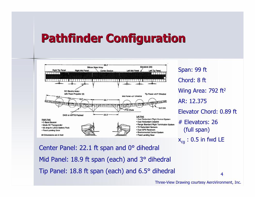
Pathfinder ConfigurationPathfinder Configuration
Span: 99 ft
Chord: 8 ft
Wing Area: 792 ft2
AR: 12.375
Elevator Chord: 0.89 ft
# Elevators: 26(full span)
xcg : 0.5 in fwd LECenter Panel: 22.1 ft span and 0° dihedral
Mid Panel: 18.9 ft span (each) and 3° dihedral
Tip Panel: 18.8 ft span (each) and 6.5° dihedral
Three-View Drawing courtesy AeroVironment, Inc.
5
Specs and PerformanceSpecs and Performance
•• W=550 lbs (includes 50 lbs payload)W=550 lbs (includes 50 lbs payload)•• -- W/S=0.694 W/S=0.694 psfpsf•• Solar array covers 75% of upper surface and can Solar array covers 75% of upper surface and can
generate near 8000 W at solar noongenerate near 8000 W at solar noon•• Six gearless 1.5 hp electric motors consisting of Six gearless 1.5 hp electric motors consisting of
fixedfixed--pitched, 2pitched, 2--bladed 79bladed 79--inch diameter props, inch diameter props, brushless DC motor, nacelle, cooling fins, and brushless DC motor, nacelle, cooling fins, and composite mounting strutcomposite mounting strut
•• -- T/W=0.10 at 60,000 ft, P/W = 13.6 W/lbT/W=0.10 at 60,000 ft, P/W = 13.6 W/lb•• Composed of carbon composite spar, lightweight Composed of carbon composite spar, lightweight
composite ribs and transparent plastic wing skincomposite ribs and transparent plastic wing skin•• -- Can withstand 3.2gCan withstand 3.2g•• Flight speed of 94 ft/s at altitude of 60,000 ftFlight speed of 94 ft/s at altitude of 60,000 ft
6
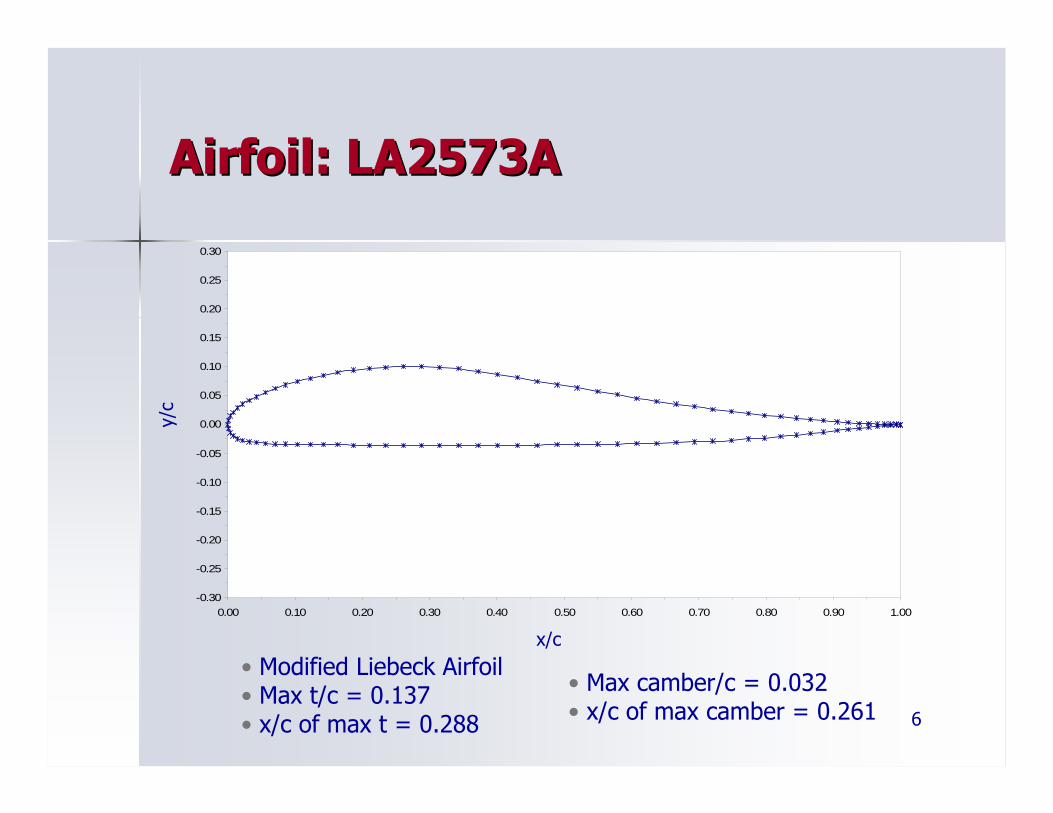
Airfoil: LA2573AAirfoil: LA2573A
• Modified Liebeck Airfoil• Max t/c = 0.137• x/c of max t = 0.288
• Max camber/c = 0.032• x/c of max camber = 0.261
x/c
-0.30
-0.25
-0.20
-0.15
-0.10
-0.05
0.00
0.05
0.10
0.15
0.20
0.25
0.30
0.00 0.10 0.20 0.30 0.40 0.50 0.60 0.70 0.80 0.90 1.00
y/c
7
-2.5
-2
-1.5
-1
-0.5
0
0.5
1
1.50 0.2 0.4 0.6 0.8 1
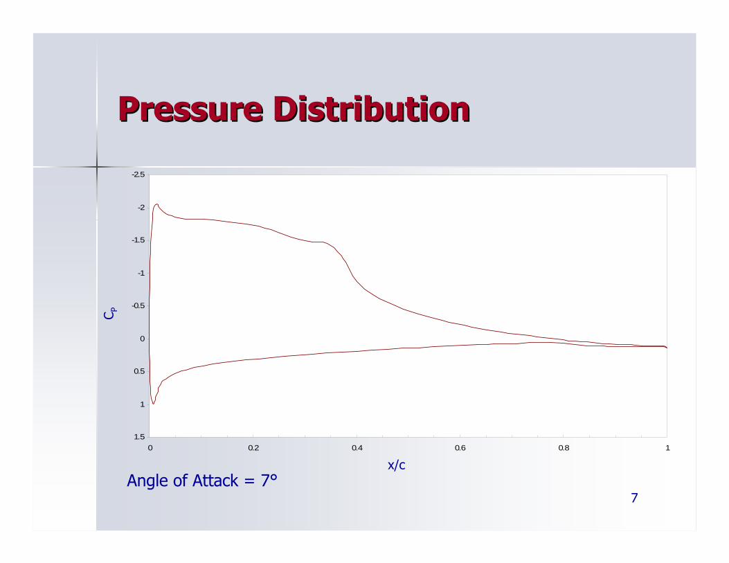
Pressure DistributionPressure Distribution
Angle of Attack = 7°x/c
C P
8
-0.4
-0.2
0.0
0.2
0.4
0.6
0.8
1.0
1.2
1.4
-4 -2 0 2 4 6 8 10 12 14 16 18
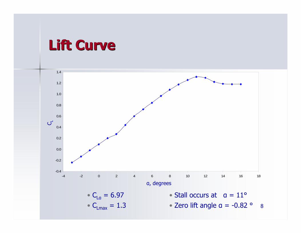
Lift CurveLift Curve
• CLα = 6.97• CLmax = 1.3
• Stall occurs at α = 11°• Zero lift angle α = -0.82 °
α, degrees
C L
9
-0.04
-0.02
0.00
0.02
0.04
0.06
0.08
0.10
0.12
0.14
-4 -2 0 2 4 6 8 10 12 14 16 18
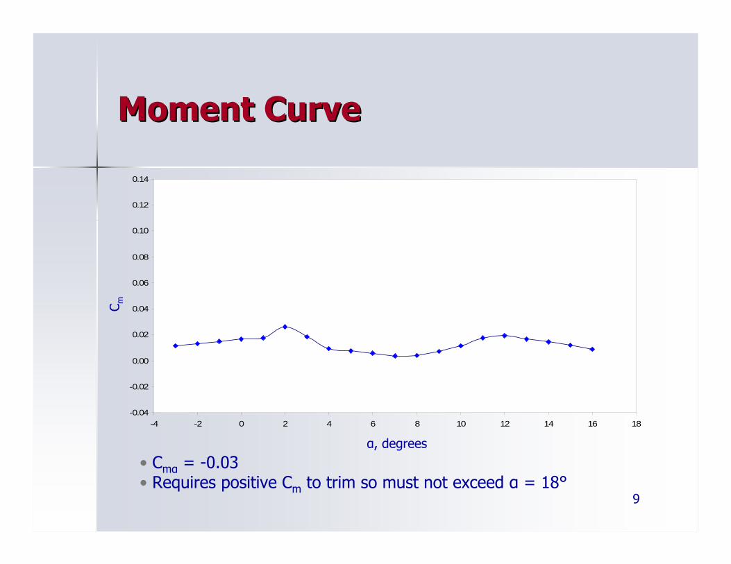
Moment CurveMoment Curve
• Cmα = -0.03• Requires positive Cm to trim so must not exceed α = 18°
α, degrees
C m
10
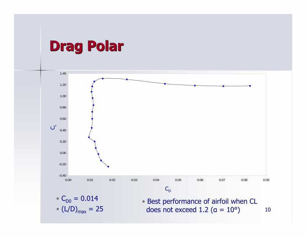
Drag PolarDrag Polar
• CD0 = 0.014• (L/D)max = 25
• Best performance of airfoil when CLdoes not exceed 1.2 (α = 10°)
CD
C L
-0.40
-0.20
0.00
0.20
0.40
0.60
0.80
1.00
1.20
1.40
0.00 0.01 0.02 0.03 0.04 0.05 0.06 0.07 0.08 0.09
11
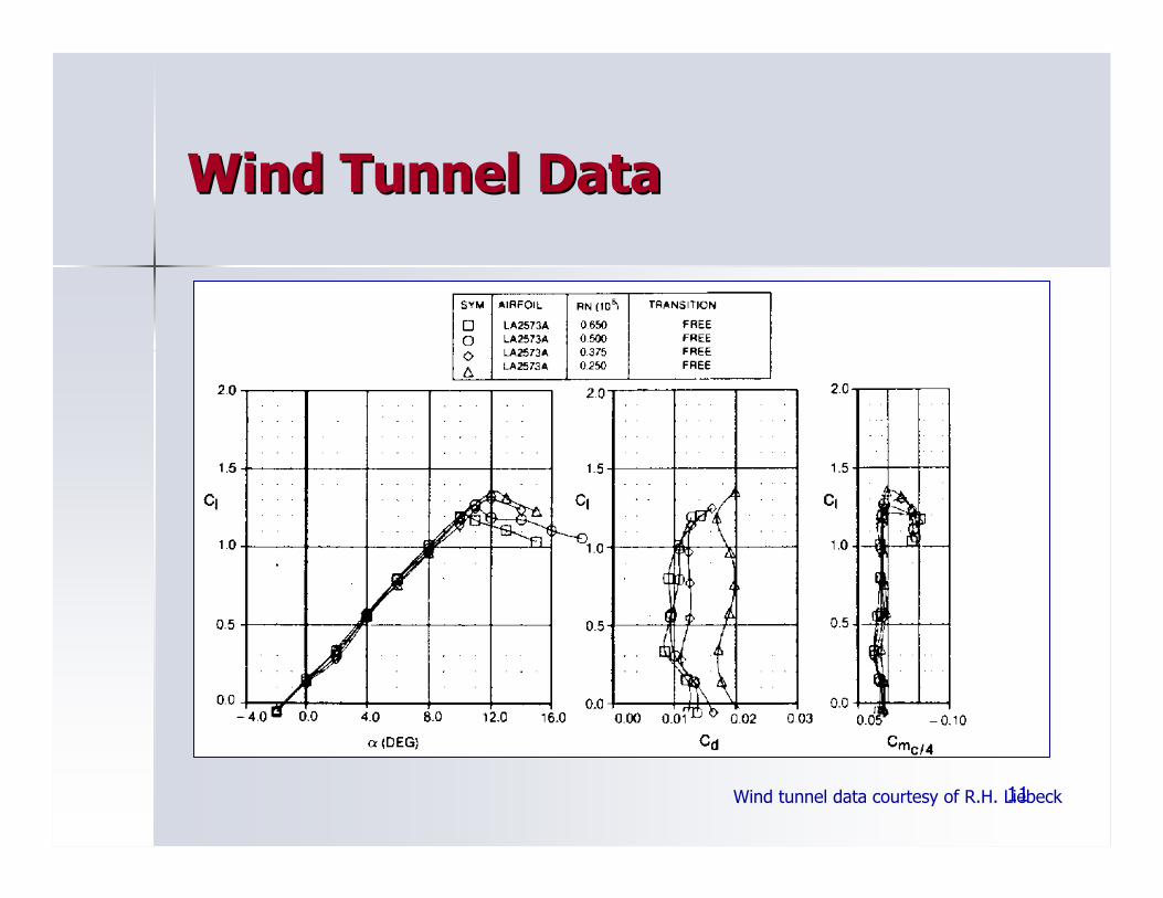
Wind Tunnel DataWind Tunnel Data
Wind tunnel data courtesy of R.H. Liebeck
12
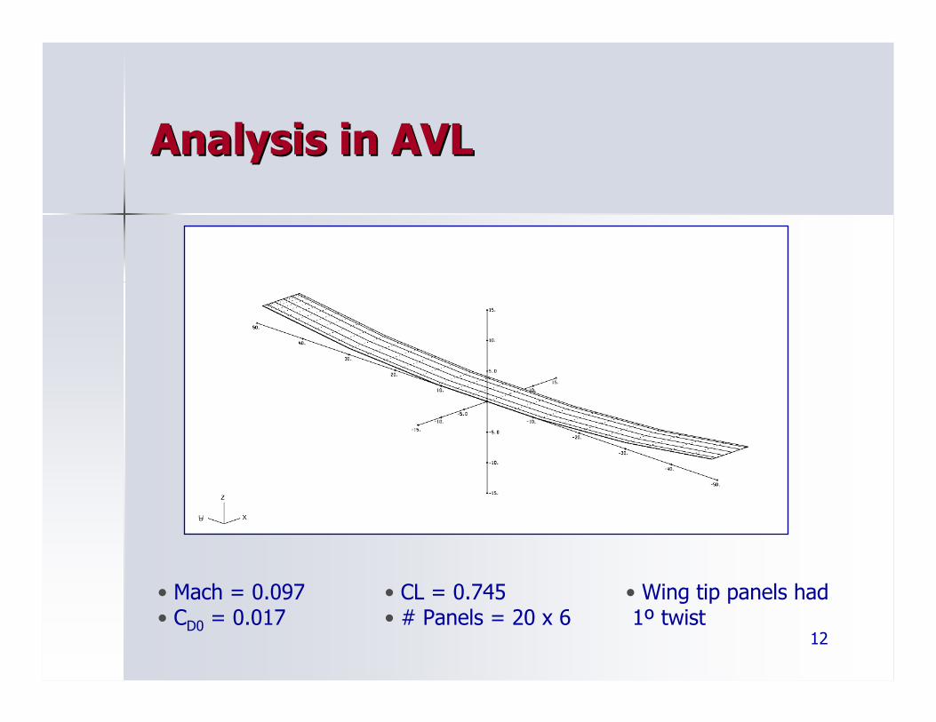
Analysis in AVLAnalysis in AVL
• Mach = 0.097• CD0 = 0.017
• CL = 0.745• # Panels = 20 x 6
• Wing tip panels had1º twist
13
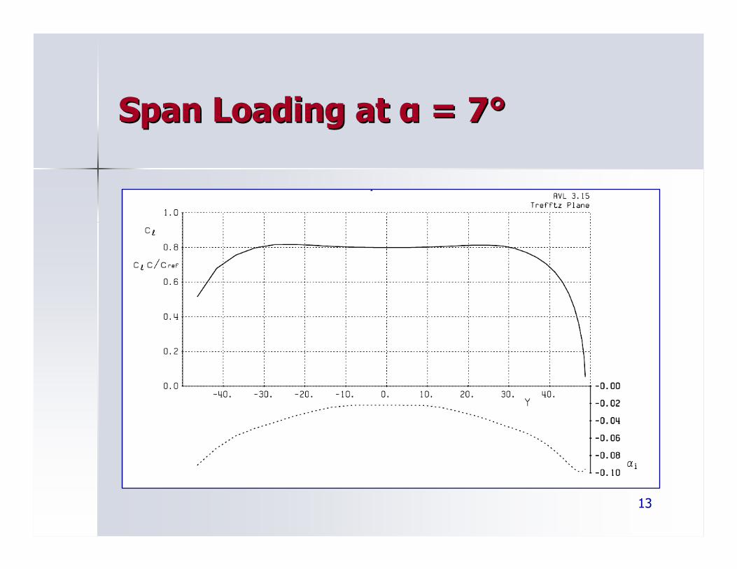
Span Loading at Span Loading at αα = 7= 7°°
14
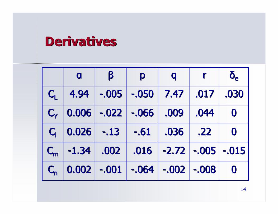
DerivativesDerivatives
00--.008.008--.002.002--.064.064--.001.0010.0020.002CCnn
--.015.015--.005.005--2.722.72.016.016.002.002--1.341.34CCmm
00.22.22.036.036--.61.61--.13.130.0260.026CCll
00.044.044.009.009--.066.066--.022.0220.0060.006CCYY
.030.030.017.0177.477.47--.050.050--.005.0054.944.94CCLL
δδeerrqqppββαα
15
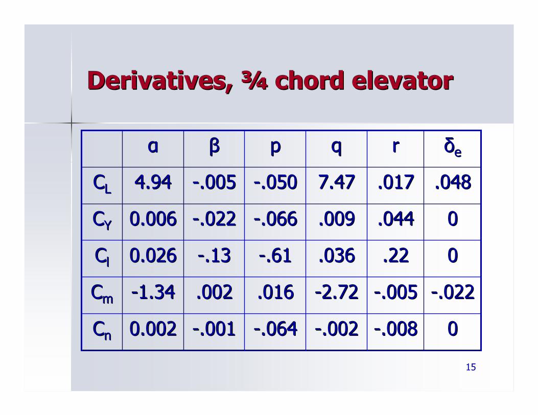
Derivatives, Derivatives, ¾¾ chord elevatorchord elevator
00--.008.008--.002.002--.064.064--.001.0010.0020.002CCnn
--.022.022--.005.005--2.722.72.016.016.002.002--1.341.34CCmm
00.22.22.036.036--.61.61--.13.130.0260.026CCll
00.044.044.009.009--.066.066--.022.0220.0060.006CCYY
.048.048.017.0177.477.47--.050.050--.005.0054.944.94CCLL
δδeerrqqppββαα
16
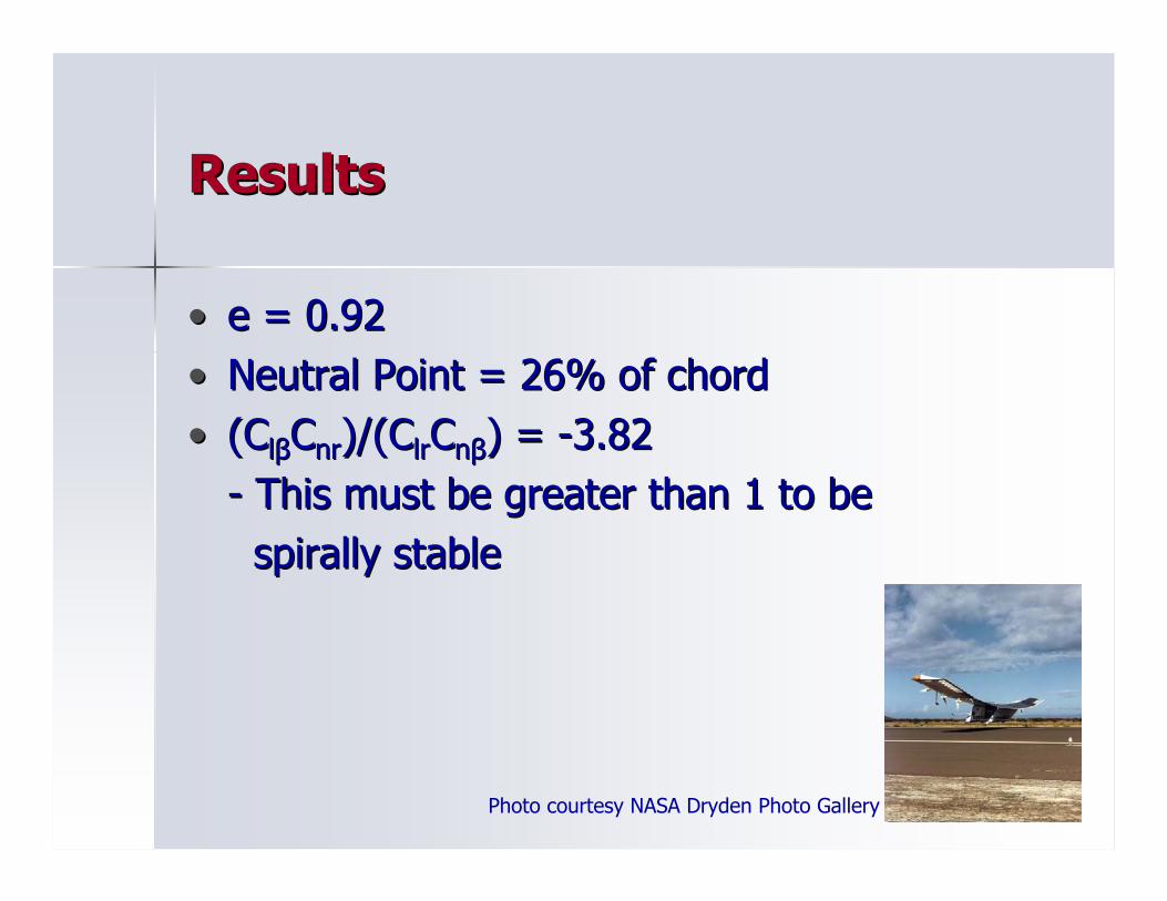
ResultsResults
•• e = 0.92e = 0.92•• Neutral Point = 26% of chordNeutral Point = 26% of chord•• ((CCllββCCnrnr)/(C)/(ClrlrCCnnββ) = ) = --3.823.82
-- This must be greater than 1 to beThis must be greater than 1 to bespirally stablespirally stable
Photo courtesy NASA Dryden Photo Gallery
17
Optimization of PlanformOptimization of Planform
• Objectives:- Maximize Power- Minimize Weight- Minimize Drag
• Design Variables:- Spans of center, mid, and tip panels- Chord
• Create model in Model Center using MATLAB modulesfor weight, drag and power
• Use the Darwin genetic algorithm to perform multi-objective optimization
18
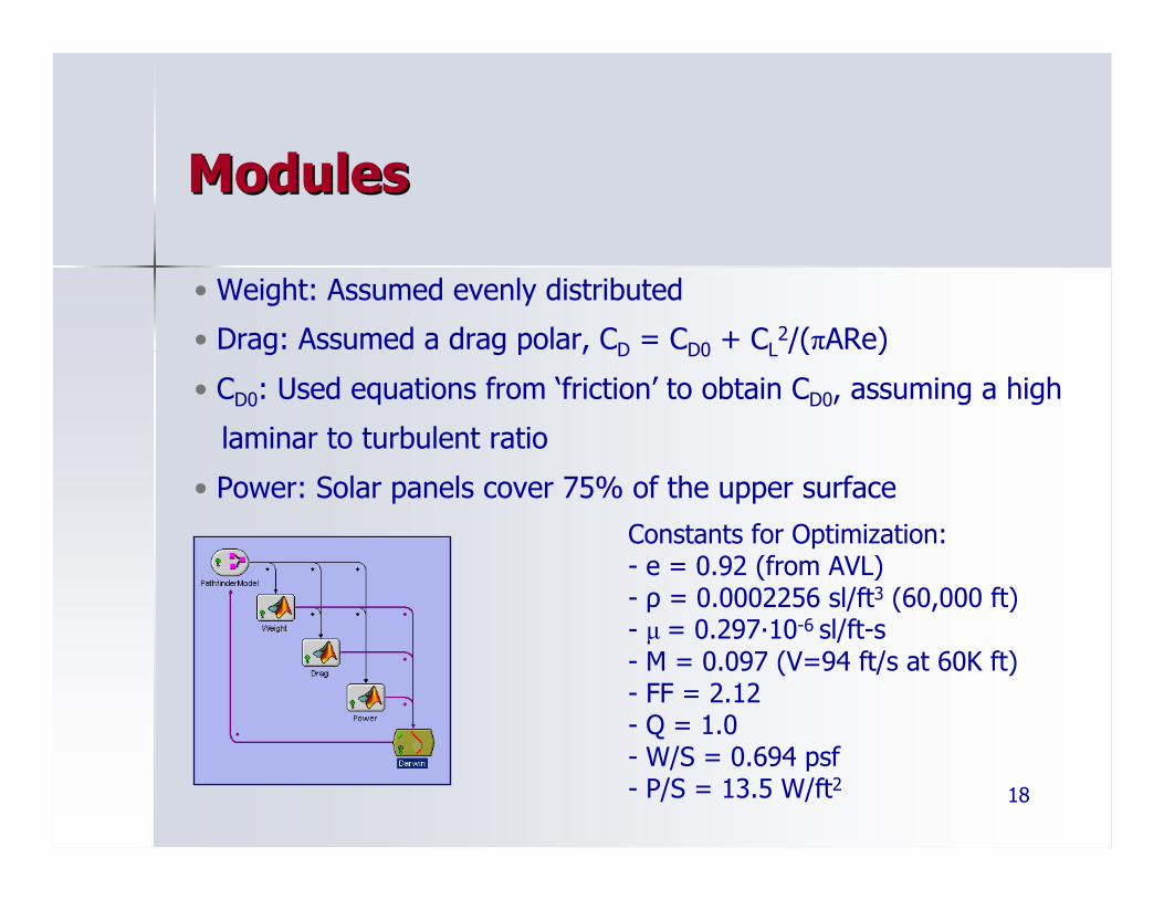
ModulesModules
• Weight: Assumed evenly distributed
• Drag: Assumed a drag polar, CD = CD0 + CL2/(πARe)
• CD0: Used equations from ‘friction’ to obtain CD0, assuming a high
laminar to turbulent ratio
• Power: Solar panels cover 75% of the upper surfaceConstants for Optimization:- e = 0.92 (from AVL)- ρ = 0.0002256 sl/ft3 (60,000 ft)- µ = 0.297·10-6 sl/ft-s- M = 0.097 (V=94 ft/s at 60K ft)- FF = 2.12 - Q = 1.0- W/S = 0.694 psf- P/S = 13.5 W/ft2
19
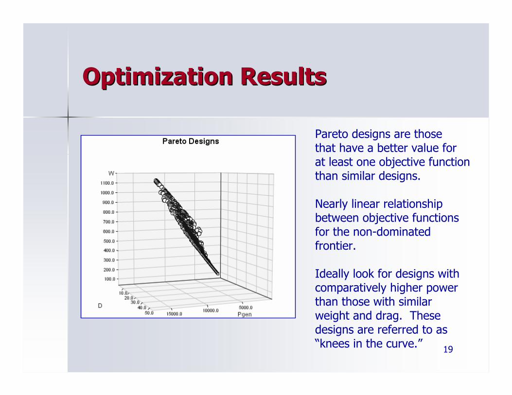
Optimization ResultsOptimization Results
Pareto designs are those that have a better value forat least one objective functionthan similar designs.
Nearly linear relationshipbetween objective functionsfor the non-dominatedfrontier.
Ideally look for designs withcomparatively higher powerthan those with similarweight and drag. Thesedesigns are referred to as“knees in the curve.”
20
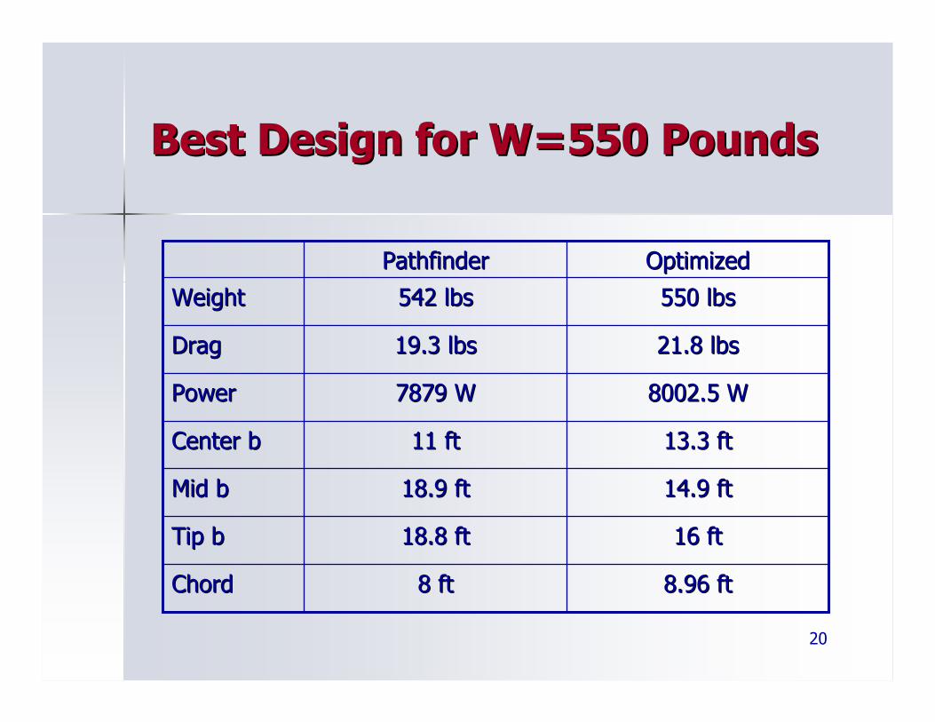
Best Design for W=550 PoundsBest Design for W=550 Pounds
550 lbs550 lbs542 lbs542 lbsWeightWeight
21.8 lbs21.8 lbs19.3 lbs19.3 lbsDragDrag
8002.5 W 8002.5 W 7879 W7879 WPowerPower
8.96 ft8.96 ft8 ft8 ftChordChord
16 ft16 ft18.8 ft18.8 ftTip bTip b
14.9 ft14.9 ft18.9 ft18.9 ftMid bMid b
13.3 ft13.3 ft11 ft11 ftCenter bCenter b
OptimizedOptimizedPathfinderPathfinder
21
ReferencesReferences
•• Curtin, Bob and Kirk Curtin, Bob and Kirk FlittieFlittie. . ““Pathfinder SolarPathfinder Solar--Powered Aircraft Flight Performance.Powered Aircraft Flight Performance.”” AIAA, AIAA, 1998.1998.
•• Noll, Thomas E, et al. Noll, Thomas E, et al. ““Investigation of the Helios Prototype Aircraft Mishap.Investigation of the Helios Prototype Aircraft Mishap.”” NASA, 2004.NASA, 2004.•• LiebeckLiebeck, R. H. , R. H. ““Laminar Separation Bubbles And Airfoil Design at Low Reynolds NuLaminar Separation Bubbles And Airfoil Design at Low Reynolds Numbers.mbers.””
AIAA, 1992. AIAA, 1992. •• SolarSolar--Powered Research and Dryden Fact Sheet, avail. at NASA DFRC websPowered Research and Dryden Fact Sheet, avail. at NASA DFRC website:ite:
http://www.nasa.gov/centers/dryden/news/FactSheets/FShttp://www.nasa.gov/centers/dryden/news/FactSheets/FS--054054--DFRC.htmlDFRC.html•• NASA Dryden Photo Gallery, avail at NASA DFRC website:NASA Dryden Photo Gallery, avail at NASA DFRC website:
http://www.dfrc.nasa.gov/gallery/index.htmlhttp://www.dfrc.nasa.gov/gallery/index.html•• UIUC Airfoil Coordinates Database, avail. at UIUC website:UIUC Airfoil Coordinates Database, avail. at UIUC website:
http://www.ae.uiuc.edu/mhttp://www.ae.uiuc.edu/m--selig/ads/coord_database.htmlselig/ads/coord_database.html•• The Incomplete Guide to Airfoil Usage, avail. at UIUC website:The Incomplete Guide to Airfoil Usage, avail. at UIUC website:
http://www.ae.uiuc.edu/mhttp://www.ae.uiuc.edu/m--selig/ads/aircraft.htmlselig/ads/aircraft.html•• XfoilXfoil Source and Materials:Source and Materials:
http://raphael.mit.edu/xfoil/http://raphael.mit.edu/xfoil/•• AVL Source and Materials:AVL Source and Materials:
http://web.mit.edu/drela/Public/web/avl/http://web.mit.edu/drela/Public/web/avl/•• MATLAB, courtesy MATLAB, courtesy MathWorksMathWorks•• Model Center, courtesy Phoenix IntegrationModel Center, courtesy Phoenix Integration
Photo courtesy NASA Dryden Photo Gallery
22
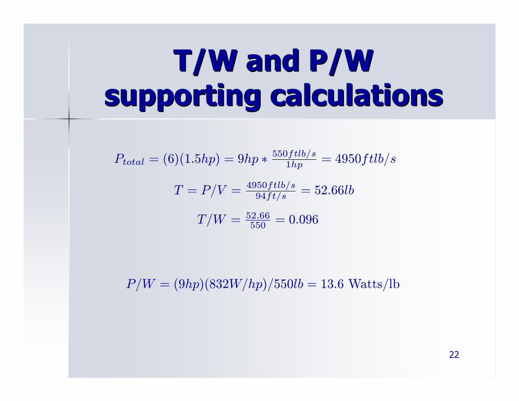
T/W and P/W T/W and P/W supporting calculationssupporting calculations
Ptotal = (6)(1.5hp) = 9hp ∗ 550ftlb/s1hp = 4950ftlb/s
T = P/V = 4950ftlb/s94ft/s = 52.66lb
T/W = 52.66550 = 0.096
P/W = (9hp)(832W/hp)/550lb = 13.6 Watts/lb


![PlAne-hoPPer s K Andboo - The Trove [multi]/1st Edition...Legends, Pathfinder Map Pack, Pathfinder Module, Pathfinder Pawns, Pathfinder Player Companion, Pathfinder Roleplaying Game,](https://img.pdfslide.us/doc/110x75/60c09751c0e51316cd1dc344/plane-hopper-s-k-andboo-the-trove-multi1st-edition-legends-pathfinder-map.jpg)
![The Trove [multi]/1st... · PATHFINDER RPG CORE RULEBOOK , PATHFINDER RPG BESTI ARY , PATHFINDER RPG BESTIARY 2 , PATHFINDER RPG BESTIARY 3 , PATHFINDER RPG ADVANCED PLAYER S GUID](https://img.pdfslide.us/doc/110x75/60c7beb87d66ea6048574996/the-trove-multi1st-pathfinder-rpg-core-rulebook-pathfinder-rpg-besti-ary.jpg)