Embed Size (px)
Citation preview
HalbhermetischeSchrauben-verdichter
Semi-hermeticScrewCompressors
Compresseurs àvis hermétiquesaccessibles
SP-100-2
R134a ! R404A ! R507A ! R22
Version 50 Hz

Halbhermetische Schraubenver-dichter Serien "HS.53/HS.64/HS.74"18,5 bis 66 kW Nominalleistung
Mit den Schraubenverdichtern der Serien"HS.53", "HS.64" und "HS.74" setzt BITZERMaßstäbe in Technik und Leistung. Dieseweiterentwickelten Baureihen sind dasErgebnis intensiver Forschung auf derGrundlage langjähriger Erfahrung imBau von Schraubenverdichtern kleinerund mittlerer Leistungsgröße.
Die herausragenden Merkmale
❏ Hohe Leistung und Wirtschaftlichkeitdurch• perfekte Profilform• hohen Motorwirkungsgrad• Möglichkeit für Economiser-Betrieb• präzise Fertigung
❏ Einfacher, robuster Aufbau
❏ Großzügige Lagerdimensionierung
❏ Effiziente Leistungsregelung als Standard-Ausrüstung (übernimmtauch Funktion der Anlaufentlastung)
❏ Integriertes Rückschlagventil
❏ Integriertes Druckentlastungs-Ventil
❏ Großvolumiger Motor für Direkt- oderPart-Winding-Anlauf
❏ Motorschutz-Einrichtung mit• thermischer Überwachung der
Wicklungstemperatur (6 PTC-Widerstände)
• Drehfeld (Drehrichtungs)-Absiche-rung
• Fehlphasen (Asymetrie)-Kontrollebei "HS.64", "HS.74"
• Wiedereinschalt-Verzögerung(gegen unkontrollierte Schalthäufig-keit) bei "HS.64", "HS.74"
❏ Druckgas-Überhitzungsschutz (PTC)
❏ Elektronische Öldurchfluss-Kontrolle
❏ Öl-Feinfilter
❏ Geeignet für R134a, R404A, R507Aund R22 – andere Kältemittel aufAnfrage
❏ Niedriges Geräusch- und Schwin-gungsniveau
❏ Geringer Platzbedarf (hohe Lei-stungsdichte)
❏ Niedriges Gewicht
Semi-hermetic Screw Compres-sors Series "HS.53/HS.64/HS.74"18.5 to 66 kW nominal capacity
The "HS.53", "HS.64" and "HS.74" seriesof screw compressors from BITZER setthe standards in technology and perfor-mance. These further developed seriesare the result of intensive researchbased on the many years of experiencein the manufacture of screw compres-sors in small and medium capacities.
The outstanding features
❏ High capacity and efficiency due to • perfect profile form• high motor efficiency• possibility of Economiser operation• precise machining
❏ Simple and robust construction
❏ Generously dimensioned bearings
❏ Efficient capacity control as standard(also takes over the function of thestart unloader)
❏ Built-in check valve
❏ Internal pressure relief valve
❏ Large-volume motor for direct orpart-winding start
❏ Motor protection device with• thermal monitoring of the winding
temperature (6 PTC resistances)• phase sequence (direction of
rotation) protection• monitoring phase symmetry
for "HS.64", "HS.74"• restart time delay (against short
cycling) for "HS.64", "HS.74
❏ Discharge gas temperature protection (PTC)
❏ Electronic oil flow switch
❏ Oil fine filter
❏ Suitable for R134a, R404A, R507Aand R22 – other refrigerants uponrequest
❏ Low noise and vibration levels
❏ Small space requirement (high power density)
❏ Low weight
Compresseurs à vis semi-hermé-tiques Séries "HS.53/HS.64/HS.74"Puissance nominale de 18,5 à 66 kW
Avec les nouveaux compresseurs à vis desséries "HS.53", "HS.64" et "HS.74", BITZERpose les jalons pour la technique et la per-formance. L'évolution technique de cesséries est le résultat de recherches inten-sives basées sur l'expé-rience acquise aucours de longues années dans la construc-tion de compresseurs à vis de petites etmoyennes puissances.
Les points marquants
❏ Puissance et rendement élevés grâce à• une forme de profil parfaite• un rendement de moteur élevé• la possibilité pour "Economiseur" • une finition précise
❏ Conception simple et robuste
❏ Roulements largement dimensionnés
❏ Régulation de puissance efficiente enéquipement standard (reprend égale-ment la fonction du démarrage à vide)
❏ Clapet de retenue intégré
❏ Soupape de surpression incorporée
❏ Moteur volumineux pour démarragedirect ou part-winding
❏ Dispositif de protection du moteur avec:• surveillance thermique de la tempéra-
ture des enroulements (6 PTC/CTP)• contrôle du champ tournant (sens de
rotation)• détection de phase(s) manquante(s}
(asymétrie) pour "HS.64", "HS.74"• temporisation au redémarrage (pour
éviter une fréquence de démarrageincontrôlée) pour "HS.64", "HS.74"
❏ Protection contre la surchauffe des gaz(PTC/CTP)
❏ Contrôle électronique du flux d'huile
❏ Filtre à huile fin
❏ Approprié pour R134a, R404A, R507A etR22 – autres fluides sur demande
❏ Niveau sonore faible et peu de vibrations
❏ Encombrement minime (puissance volu-mique élevée)
❏ Poids réduit
2

1 Konstruktiver AufbauFunktionsweise
1.1Allgemeine Konstruktionsmerkmale
BITZER-Schraubenverdichter sind zwei-wellige Rotations-Verdrängungsmaschi-nen mit hoch effizienter Profilgeometrie.Die wesentlichen Bestandteile dieserVerdichter sind die beiden Rotoren(Haupt- und Nebenläufer), die in eingeschlossenes Gehäuse eingepasstsind.Die Rotoren sind beidseitig wälzgela-gert (radial und axial), wodurch eineexakte Fixierung dieser Teile und – inVerbindung mit reichlich bemessenenÖlvorratskammern – optimale Notlauf-Eigenschaften gewährleistet sind. AufGrund der spezifischen Ausführungbenötigt diese Verdichter-Bauart keineArbeitsventile. Zum Schutz gegenRückwärtslauf (Expansionsbetrieb) imStillstand, ist in die Druckkammer einRückschlagventil eingebaut (diesesVentil ersetzt jedoch nicht durch dieAnlagen-Konzeption eventuell bedingteRückschlagventile).
Als Berstschutz dient ein integriertesDruckentlastungs-Ventil.
1 ConstructionFunctioning
1.1Construction features
BITZER screw compressors are of two-shaft rotary displacement design withhigh-efficiency profile geometry. Themain parts of these compressors arethe two rotors (male and female rotor)which fit in a closed housing. The rotorsare precisely located at both ends inrolling contact bearings (radial andaxial) which in conjunction with gener-ously sized oil supply chambers pro-vides optimal emergency running char-acteristics. Owing to the specificdesign, this compressor type does notrequire any working valves. To protectagainst reverse running when the com-pressor is switched off (expansionoperation) a check valve is incorporat-ed in the discharge chamber (thisvalve, however, does not replace anycheck valves required by the systemdesign).
An internal pressure relief valve acts asbursting protection.
1 Caractéristiques de constructionMode de fonctionnement
1.1Généralités
Les compresseurs à vis BITZER sont desmachines rotatives volumétriques à 2arbres, dotées d'une géométrie de profil trèsefficient. Les composants essentiels de cescompresseurs sont les deux rotors (rotorprincipal et auxiliaire), qui sont incorporésavec une grande précision dans un bâti. Lepositionnement (axial et radial) de ces rotorsest assuré, aux deux extrêmités, par despaliers à roulements. Il résulte de cetteconstruction un positionnement rigoureuxdes divers éléments, ce qui avec – de sur-croît – des chambres de réserve d'huile lar-gement dimensionnées, garantit à cesmachines des propriétés optimales de fonc-tionnement exceptionnel en cas d'urgence.De par sa conception spécifique, ce type decompresseur ne nécessite pas de clapetsde travail. Pour éviter à l’arrêt une marcheen sens inverse, qui serait causée par l'ex-pansion des gaz, un clapet anti-retour a étéinstallé dans la chambre de compression.Remarquons cependant que ce clapet neremplace pas d'autres clapets, qui seraientnécessaires par la conception d'ensemblede l'installation.
Une soupape de surpression incorporéeassure la protection contre un éclatementéventuel.
3
Der Antrieb erfolgt durch einen Dreh-strom-Asynchronmotor, der in einem ver-längerten Verdichtergehäuse eingebaut ist.
Dabei ist der Läufer des Motors auf derWelle des Haupt-Schraubenrotorsangeordnet.
Die Kühlung geschieht durch kalten Kältemitteldampf, der im wesentlichendurch Bohrungen im Läufer geleitetwird. Neben der intensiven Kühlungwird durch diese Bauart gleichzeitig dieFunktion eines Zentrifugal-Flüssigkeits-abscheiders erreicht.
The compressor is driven by a three-phase asynchronous motor which isbuilt into an extended compressor hou-sing. The motor rotor is located on theshaft of the male screw rotor.
Cooling is achieved by cold refrigerantvapour, which mainly flows through thebores in the rotor. In addition to intensi-ve cooling, this design also incorpora-tes the function of a centrifugal liquidseparator.
L'entraînement se fait par l'intermédiaired'un moteur asynchrone triphasé incorporédans le carter compresseur rallongé. C'estainsi que le rotor du moteur (induit) estpositionné sur l'arbre du rotor principal ducompresseur à vis.
Le refroidissement s'effectue par lesvapeurs froides de réfrigérant, qui sontessentiellement véhiculées à travers desalésages dans le rotor du moteur.
En plus, de ce refroidissement intensif, cetype de construction assure la fonction deséparation de liquide par effet centrifuge.
1.2 VerdichtungsvorgangVi-Regelung
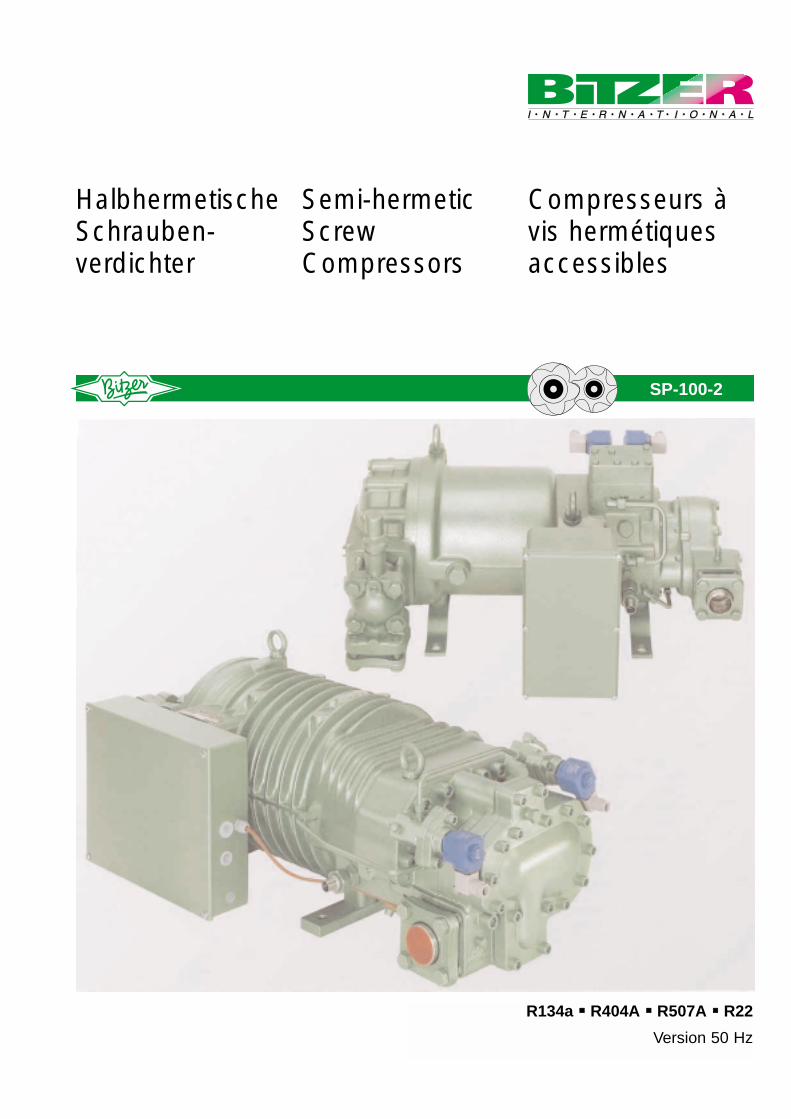
Bei Schraubenverdichtern erfolgt derVerdichtungsvorgang im Gleichstrom.Dabei wird das angesaugte Gas beiaxialer Förderung in der sich stetigverkleinernden Zahnlücke komprimiert.Das verdichtete Gas wird dann durchein Austrittsfenster ausgeschoben,dessen Größe und Form das sog."eingebaute Volumenverhältnis (Vi)"bestimmt. Diese Kenngröße muss ineiner definierten Beziehung zumMassenstrom und Arbeitsdruckverhält-nis stehen, um größere Wirkungsgrad-verluste durch Über- oder Unterkom-pression zu vermeiden.
Die Austrittsfenster sind bei BITZER-Schraubenverdichtern für besondersbreite Anwendungsbereiche ausgelegt.Es werden dabei zwei Varianten proVerdichtergröße unterschieden:
• HSK-Modelle für Klima- und Normalkühlung
• HSN-Modelle für Tiefkühlung
Mit Blick auf hohe Effizienz und Betriebs-sicherheit wird ein sog. “Duo-Port” ver-wendet. Hierbei handelt es sich um einFenster mit spezieller Kontour, daseinen zusätzlichen radialen Auslassaufweist. Hierdurch passt sich dasAbströmverhalten den verschiedenenBetriebsbedingungen dynamisch an.Dies führt zu hoher Kälteleistung undLeistungszahl über den gesamtenAnwendungsbereich und der Einbaueines zusätzlichen mechanischenReglers entfällt.
Zudem lassen sich bei hohen Druckver-hältnissen (z. B. Tiefkühlung) durchAnheben des Massen-Durchsatzes mit-tels “Economiser-Betrieb” ein weitge-hend idealer Verdichtungsverlauf (sieheBild) und damit beste Verdichter- undAnlagen-Wirkungsgrade erreichen.
1.2 Processus de compressionRégulation Vi
Dans le cas des compresseurs à vis, leprocessus de compression s’effectue enflux continu. Ainsi, les gaz aspirés sontvéhiculés axialement et comprimés dansles interstices entre les profils qui seréduisent progressivement. Les gaz com-primés sont refoulés ensuite par unefenêtre de sortie dont la taille et la formedéterminent le “rapport de volume intégré”(Vi). Ce paramètre doit être en relationdirecte avec le flux de masse et le rapportdes pressions de travail afin d’éviter despertes de rendement trop importantes parsur- ou sous-compression.
Les fenêtres de sortie des compresseurs àvis BITZER sont définies pour des plagesd’application très larges. Il faut distinguerentre deux variantes par taille de com-presseur:
• Modèles HSK pour conditionnementd’air et réfrigération.
• Modèles HSN pour basses températures
L’emploi du “Duo Port” permet d’envisagerune efficience et une sécurité de fonction-nement élevées. Il s’agit ici d’une fenêtreayant un contour spécial avec une sortieradiale supplémentaire. Ainsi, le comporte-ment de l’écoulement, s’adapte de façondynamique aux différentes conditions defonctionnement. Il en résulte une puissancefrigorifique et un coefficient de perfor-mance élevés sur toute l’étendue de laplage d’application, et ceci sans régulateurmécanique supplémentaire.
De plus, pour des rapports de pressionélevés (emploi en basses températures parex.), il est possible, par élévation du débitmassique à l’aide du “fonctionnement avecéconomiseur”, d’atteindre un processus decompression pratiquement idéal (voir fig-ure) et par conséquent, avoir de très bonsrendements sur le compresseur et surl’installation.
1 Verdichtungsverlauf2 Verlauf bei hohem Druckverhältnis und
Economiser-Betrieb3 Austrittsdruck bei idealem Verdichtungsverlauf4 Verluste durch Überkompression5 Verluste durch Unterkompression
1 Compression behaviour2 Behaviour with high pressure ratio and
Economiser operation3 Internal port pressure with ideal compression4 Losses by over-compression5 Losses by under-compression
1 Processus de compression2 Processus pour rapport de pressions élevé et fonc-
tionnement économiseur3 Pression de sortie pour processus de compression idéal4 Pertes par surcompression5 Pertes par sous-compression
4
P1
P2
P i
P1
Pi
P2
V2 V1 V2 V1
Pi (ECO)
ECO
3
1P / V
4
2
1
5
P / V
1.2 Compression processVi control
With screw compressors, suction, com-pression and discharge occur in oneflow direction. With this process thesuction gas is pressed into the profilehallows by the profile peaks, the volumeis steadily reduced and it is therebycompressed. The compressed gas isthen discharged through a dischargeport whose size and geometry deter-mine the so called “internal volume ratio (Vi). This value must have adefined relationship to the workingpressure ratio, to avoid losses in effi-ciency due to over- or under-compres-sion.
The discharge ports of BITZER screwcompressors are designed for especial-ly wide application ranges. These aredistinguished by two variations percompressor size:
• HSK-Models for high- and mediumtemperature
• HSN-Models for low temperature
In view of high efficiency and opera-tional safety a so-called “Duo-Port” isused. This is characterized by a specialport contour with an additional radialoutlet. This enables a dynamic flow-offbehavior matching the various opera-tion conditions. Results are high capac-ity and high COP across the entireapplication range and the omission ofan additional mechanic control device.
Moreover, with high compression ratios(e.g. low temperature cooling) a largelyideal compression process (see figure)and accompanied highest possiblecompressor- and system efficienciescan be achieved with increased massflow by means of “Economiser opera-tion”.

Konstruktiver Aufbau der Leistungsregelung(Anlaufentlastung)
Construction details of the capacity control (start unloading)
Détails de construction de la régulation de puissance(démarrage à vide)
5
SteuerkolbenControl pistonPiston de commande
Magnetventil (stromlos)Solenoid coil (de-energized)
Vanne magnétique (non-alimentée)
SteuerölControl oilHuile de commande
Magnetventil (unter Spannung)Solenoid coil (energized)
Vanne magnétique (alimentée)
Teillastbetrieb / AnlaufentlastungPart load operation / Start unloadingFonctionnement en charge partielle / Démarrage à vide
VollastbetriebFull load operationFonctionnement en pleine charge
1.3 Leistungsregelung Anlaufentlastung
Für diese Verdichter wurde ein neuartiges,mehrstufiges Reglersystem entwickelt,welches im Funktionsprinzip dem desSteuerschiebers bei der CS-Serie undgrößeren Schraubenverdichtern entspricht.Zur Leistungsregelung wird das wirksameAnsaugvolumen durch Verschieben derAnsaugsteuerkante in zwei Schritten ver-ringert und dadurch der Volumenstromentsprechend reduziert. Dabei wird die Rei-henfolge der Reglerstufen beim Lastwech-sel jeweils beachtet (definierte Sequenz fürdie Ansteuerung der Magnetventile).
Im Gegensatz zu Verdichtern mit Schieberbesteht die Reglereinheit aus hydraulischbetätigten Kolben, die bei Volllast-Betriebabsolut formschlüssig an Stirnflansch (axialeKolben) bzw. Profilraum (radialer Kolben)anliegen. Damit wird eine besonders hoheStabilität des Gehäuses erreicht und dieSpalte zwischen Rotoren und Gehäusebleiben auch bei hoher Temperatur- undDruckbelastung in engen Grenzen. DieseMaßnahme ist bei kleineren Schrauben-verdichtern ein wichtiger Entwicklungsschrittfür einen guten Gesamt-Wirkungsgrad.
Durch die direkte hydraulische Betätigungder Reglerkolben bedarf es zum Schutzgegen Flüssigkeitsschläge und zur Anlauf-entlastung keiner zusätzlichen Bauteile. DieKolben öffnen immer dann, wenn der Druckim Verdichtungsraum über deren Betäti-gungsdruck liegt, dies ist i. d. R. der Öl-bzw. Verflüssigungsdruck. Somit ist eineautomatische Anlaufentlastung ebensogewährleistet wie ein Schutz vor starker Überverdichtung.
Für den Teillast-Betrieb bewegen sich dieKolben nacheinander (durch bedarfsab-hängige, zeitlich verzögerte Steuerung) indie rückwärtige Position und geben dabeireichlich dimensionierte Öffnungen zwischenProfilraum und Saugseite frei. Dadurch ver-ringert sich das aktive Profilvolumen mit derFolge einer Leistungsreduzierung. Das Sys-tem ist für zwei Reglerstufen konzipiert, mitdenen durch intermittierendes Schalten derMagnetventile eine sehr genaue Anpassungder Verdichterleistung an den Lastzustanddes Systems erreicht werden kann.
1.3 Capacity controlStart unloading
For these compressors a new type of multi-stage control system was developed, thefunction principle of which is similar to that ofthe slide control with the CS series and larg-er screw compressors. To control capacity,the effective suction volume is reduced intwo steps by shifting the suction controledge, with a corresponding drop of the vol-ume flow. In this context the order of eachcontrol stage is complied with for loadchanges (a defined sequence for triggeringthe solenoid valves).
Unlike the compressors with slide controls,the control unit consists of hydraulicallyoperated pistons, which at full-load opera-tion form-fit with the end flange (axial pis-tons) or the profile chamber (radial pistons).In this way the housing achieves particularlyhigh stability and the gap between rotorsand housing remains within close limits,even under high temperature and pressureloads. With smaller screw compressors thismeasure is an important stage of develop-ment for a high overall efficiency.
Due to the direct hydraulic operation of thecontrol pistons, no additional componentsare required to protect against slugging orfor start unloading. The pistons always openwhen the pressure in the compressionchamber is above their operating pressurewhich is usually the oil/condensing pressure.In this way automatic start unloading is guaranteed, as is also protection againststrong over-compression.
In part-load operation the pistons move oneafter each other into the reverse position (bytime delayed on-demand control) and thuscause generously dimensioned spaces toopen up between profile chamber and suc-tion side. For this reason the active profilevolume is reduced, with a consequentialdrop in capacity. The system has beendesigned for two control steps, so that,through the intermittent switching of thesolenoid valves, it is possible to achieve avery exact match of compressor capacity tothe load condition of the system.
1.3 Régulation de puissanceDémarrage à vide
Un nouveau système de régulation à plusieursétages a été développé pour ces compresseurs.Le principe de fonctionnement est semblable àcelui du tiroir de commande de la série CS et descompresseurs à vis plus puissants. La régulationde puissance est obtenue par limitation en deuxétapes du volume aspiré par déplacement de larampe d’admission, ce qui réduit par conséquentle flux volumétrique. Avec celà, il faut toujourstenir compte de la succession des étages durégulateur lors d’une variation de la charge(séquence bien définie pour la commande desvannes magnétiques).
A l’opposé des compresseurs avec tiroir, l’unitéde régulation se compose de pistons actionnéshydrauliquement qui, en fonctionnement à pleinecharge, assurent une fermeture géométriqueabsolue sur la bride de front (pistons axiaux)respectivement sur le logement des profils (pis-tons radiaux). Une très grande stabilité du carterest aussi obtenue, et les espaces entre rotors etcarter sont maintenus dans des limites très étro-ites, même pour des températures et des chargesde pression élevées. Pour les petits compres-seurs à vis, ce développement est un pas impor-tant vers l’obtention d’un bon rendement total.
La commande hydraulique des pistons de régula-tion étant directe, il n’est pas nécessaire de faireappel à des artifices supplémentaires pour la pro-tection contre les coups de liquide et le démar-rage à vide. En effet, les pistons ouvrent toujoursquand la pression dans la chambre de compres-sion est supérieure à la pression de commandedu piston qui, en règle générale, est la pressiond’huile respectivement la pression de condensa-tion. De ce fait, un démarrage à vide automatiqueet une protection contre une trop forte surcom-pression sont garantis.
Pour le fonctionnement en réduction de puis-sance, les pistons se mettent l’un après l’autre enposition de retrait (par commande temporisée etadaptée aux besoins) et libèrent ainsi des ouver-tures largement dimensionnées entre le logementdes profils et le côté aspiration. La limitation duvolume actif des profils aboutit à une réduction depuissance. Le système est conçu pour deuxétages de régulation qui permettent, par com-mande intermittente des vannes magnétiques,une adaptation précise de la puissance du com-presseur à la charge momentanée du système.
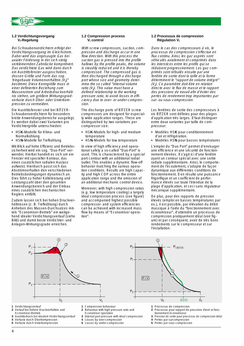
1.4 Electronic protection devices
Because of the especially highdemands concerning operational relia-bility with larger refrigeration compres-sors, the semihermetic models areequipped as standard with a Micro-
Processor controlledprotection device(HS.53: INT 69VSY-II/HS.64, HS74: INT389R).
Functions:❏ Thermal monitoring
of the winding tem-perature (6 PTCresistances)
❏ Phase sequence(direction of rota-tion) protection
❏ Discharge gas tem-perature protection(PTC)
❏ Monitoring phase symmetry for"HS.64", "HS.74"
❏ Restart time delay (against short cycling) for "HS.64", "HS.74"
❏ Monitoring oil flow (separate unit)
Faults and time delays can be fed to signal devices, over additional relayoutputs.The thermal monitoring function allowsoperation with either a lock-out or withautomatic reset.
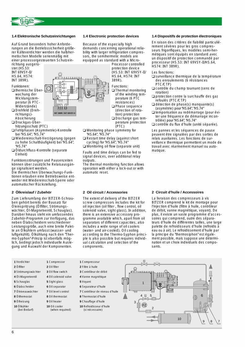
2 Oil circuit / Accessories
The extent of delivery of the BITZERscrew compressors includes the kit foroil injection (oil filter , flow control, oilsolenoid valve, sight glass). In addition,there is an extensive accessory pro-gramme available which, apart from oilseparators of different capacities, alsoincludes a wide range of oil coolers(water- and air-cooled). Oil coolingaccording to the Thermo-Syphon princi-ple is also possible but requires individ-ual calculation and selection of thecomponents.
1.4 Dispositifs de protection électroniques
En raison des critères de fiabilité particuliè-rement sévères pour les gros compres-seurs frigorifiques, les modèles semi-her-métiques sont équipés en standard avecun dispositif de protection commandé parprocesseur (HS.53: INT 69VSY-II/HS.64,HS74: INT 389R).
Les fonctions:❏ surveillance thermique de la température
des enroulements (6 résistancesPTC/CTP)
❏ contrôle du champ tournant (sens derotation)
❏ protection contre la surchauffe des gazrefoulés (PTC/CTP)
❏ détection de phase(s) manquante(s)(asymétrie) pour "HS.64", "HS.74"
❏ temporisation au redémarrage (pour évi-ter une fréquence de démarrage incon-trôlée) pour "HS.64", "HS.74"
❏ contrôle du flux d'huile (unité séparée).
Les pannes et les séquences de pausepeuvent être signalées par des sorties derelais auxiliaires. Les fonctions de sur-veillance thermique permettent un mode detravail avec réarmement manuel ou auto-matique.
2 Circuit d'huile / Accessoires
La livraison des compresseurs à vis BITZER comprend le kit de montage pourl'injection d'huile (filtre à huile, contrôleurde débit, vanne magnétique, voyant). Deplus, il existe un vaste programme d'acces-soires qui comprend, outre des sépara-teurs d'huile de différentes tailles, une largepalette de refroidisseurs d'huile (refroidis àeau ou à air). Le refroidissement d'huile parla principe du "thermosiphon" est égale-ment possible, mais suppose une détermi-nation et un choix individuels des compo-sants.
1.4 Elektronische Schutzeinrichtungen
Auf Grund besonders hoher Anforde-rungen an die Betriebssicherheit größe-rer Kälteverdichter werden die halbher-metischen Modelle serienmäßig miteiner prozessorgesteuerten Schutzein-richtung ausgerü-stet (HS.53: INT 69VSY-II/HS.64, HS74: INT 389R).
Funktionen:❏ thermische Über-
wachung derWicklungstem-peratur (6 PTC-Widerstände)
❏ Drehfeld (Dreh-richtungs)-Absicherung
❏ Druckgas-Über-hitzungsschutz (PTC)
❏ Fehlphasen (Asymmetrie)-Kontrollebei "HS.64", "HS.74"
❏ Wiedereinschalt-Verzögerung (gegenzu hohe Schalthäufigkeit) bei "HS.64","HS.74"
❏ Öldurchfluss-Kontrolle (separate Einheit)
Funktionsstörungen und Pausenzeitenkönnen über zusätzliche Relaisausgän-ge signalisiert werden.Die thermischen Überwachungs-Funk-tionen erlauben eine Betriebsweise ent-weder mit Wiedereinschalt-Sperre oderautomatischer Rückstellung.
2 Ölkreislauf / Zubehör
Zum Lieferumfang der BITZER-Schrau-ben gehört bereits der Bausatz fürÖleinspritzung (Ölfilter, Strömungs-wächter, Öl-Magnetventil, Schauglas).Darüber hinaus steht ein umfassendesZubehör-Programm zur Verfügung, dasneben Ölabscheidern verschiedenerLeistungsgröße, auch eine breite Palet-te an Ölkühlern umfasst (wasser- undluftgekühlt). Ölkühlung nach den "Ther-mo-Syphon"-Prinzip ist ebenfalls mög-lich, bedingt jedoch individuelle Ausle-gung und Auswahl der Komponenten.
T1
T2
SL
1
2
3
7
8
9
12345
L2 L3L1 PTC
INT 389R / INT 69VSY-II
FZ
6
10
2
3
4 5
1
89 7
6
1 Verdichter
2 Ölfilter
3 Strömungswächter
4 Öl-Magnetventil
5 Schauglas
6 Ölabscheider
7 Ölniveauwächter
8 Ölthemostat
9 Ölheizung
10 Ölkühler (bei Bedarf)
1 Compressor
2 Oil filter
3 Oil flow switch
4 Oil solenoid valve
5 Sight glass
6 Oil separator
7 Oil level control
8 Oil thermostat
9 Oil heater
10 Oil cooler(when required)
1 Compresseur
2 Filtre à huile
3 Contrôleur de débit
4 Vanne magnétique
5 Voyant
6 Separateur d'huile
7 Contrôleur de niveau d'huile
8 Thermostat d'huile
9 Chauffage d'huile
10 Refroidisseur d'huile (si nécessaire)
H S K B 6 4 6 1 - 4 0
H S K B 6 4 6 1 - 4 0
H S K B 6 4 6 1 - 4 0
H S K B 6 4 6 1 - 4 0
H S K B 6 4 6 1 - 4 0
H S K B 6 4 6 1 - 4 0
H S K B 6 4 6 1 - 4 0
4 Les applications possibles
Etendue des utilisations possibles❏ Systèmes individuels avec un seul com-
presseur*❏ Unités compactes pour des systèmes
assemblés en usine (Modèles HSKC etCS – voir prospectus SP-150 et SP-170)
❏ Centrales avec compresseurs en pa-rallèle*
❏ Systèmes à un étage (compresseur(s)unique(s) ou en parallèle) avec "Economiseur"
❏ Système à deux étages –compresseur(s) unique(s) ou en parallèle– basse pression
(Booster): Modèles HSKB– haute pression: Modèles HSK
* avec adjonction d'un séparateur d'huile, d'un refroidisseur d'huile ou autre accessoire suivant les besoins (voir Manuel SH-100).
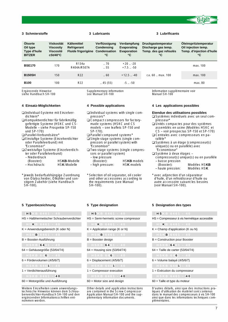
5 Typenbezeichnung
HS = Halbhermetischer Schraubenverdichter
Weitere Einzelheiten sowie anwendungs-technische Hinweise können dem Schrau-benverdichter-Handbuch SH-100 und denergänzenden Informationsschriften ent-nommen werden.
Other details and application instructionsare contained in the Screw CompressorApplication Manual SH-100 and the sup-plementary information documents.
K = Anwendungsbereich (K oder N)
B = Booster-Ausführung
64 = Gehäusegröße (53/64/74)
6 = Fördervolumen (4/5/6/7)
1 = Verdichterausführung
60 = Motorgröße und Ausführung
H S K B 6 4 6 1 - 4 0
H S K B 6 4 6 1 - 4 0
H S K B 6 4 6 1 - 4 0
H S K B 6 4 6 1 - 4 0
H S K B 6 4 6 1 - 4 0
H S K B 6 4 6 1 - 4 0
H S K B 6 4 6 1 - 4 0
5 Type designation
HS = Semi-hermetic screw compressor
K = Application range (K or N)
B = Booster design
64 = Housing size (53/64/74)
6 = Displacement (4/5/6/7)
1 = Compressor execution
60 = Motor size and design
H S K B 6 4 6 1 - 4 0
H S K B 6 4 6 1 - 4 0
H S K B 6 4 6 1 - 4 0
H S K B 6 4 6 1 - 4 0
H S K B 6 4 6 1 - 4 0
H S K B 6 4 6 1 - 4 0
H S K B 6 4 6 1 - 4 0
5 Designation des types
3 Schmierstoffe 3 Lubricants
HS = Compresseur à vis hermétique accessible
K = Champ d'application (K ou N)
B = Construction pour Booster
64 = Taille de carter (53/64/74)
6 = Volume balayé (4/5/6/7)
1 = Exécution du compresseur
60 = Taille et type du moteur
D'autres détails, ainsi que des instructions pra-tiques d'utilisation de matériel sont contenusdans le manuel des compresseurs à vis SH-100ainsi que dans les informations techniques com-plémentaires.
Ergänzende Hinweise siehe Handbuch SH-100
Supplementary information see Manual SH-100
Information supplémentaire voir Manuel SH-100
3 Lubrificants
4 Einsatz-Möglichkeiten
❏ Individual-Systeme mit Einzelver-dichtern*
❏ Kompaktverdichter für fabrikmäßiggefertigte Systeme (HSKC und CS-Modelle – siehe Prospekte SP-150und SP-170)
❏ Parallel-Verbundsätze*❏ Einstufige Systeme (Einzelverdichter
oder Parallelverbund) mit "Economiser"
❏ Zweistufige Systeme (Einzelverdich-ter oder Parallelverbund)– Niederdruck
(Booster): HSKB-Modelle– Hochdruck: HSK-Modelle
* jeweils bedarfsabhängige Zuordnungvon Ölabscheider, Ölkühler und son-stigem Zubehör (siehe Handbuch SH-100).
4 Possible applications
❏ Individual systems with single com-pressors*
❏ Compact compressors for factory-made systems (HSKC and CSmodels – see leaflets SP-150 and SP-170).
❏ Parallel compound systems*❏ Single-stage systems (single com-
pressors or parallel system) with "Economiser"
❏ Two-stage systems (single compres-sors or parallel system)– low pressure
(Booster): HSKB models– high pressure: HSK models
* Selection of oil separator, oil coolerand other accessoires according tothe requirements (see Manual SH-100).
7
ÖlsorteOil typeType d'huileBITZER
ÖleinspritztemperaturOil injection temp.Temp. d'injection d'huile
°C
DruckgastemperaturDischarge gas temp.Temp. des gaz refoulés
°C
VerdampfungEvaporatingEvaporation
°C
VerflüssigungCondensingCondensation
°C
KältemittelRefrigerantFluide frigorigène
ViskositätViscosityViscositécSt/40°C
BSE170
B150SH
B100
max. 100
max. 100
max. 80
ca. 60 .. max. 100
+20 .. -20+7.5 .. -50
+12.5 .. -40
-5 .. -50
.. 70
.. 55
.. 60
.. 45 (55)
R134aR404A/R507A
R22
R22
170
150
100

8
∆ t oh 20K
∆ t oh 20K
∆ t oh 10K
∆ t oh 20K
∆ t oh 10K
HSN
-50 -40 -10
10
20
30
40
50
60
Verf
lüss
igun
gste
mp
erat
ur
Con
den
sing
tem
per
atur
e t
c [°
C]
Tem
pér
atur
e d
e co
nden
stai
on
Verdampfung/Evaporation to [°C]
Vollastbetrieb/Full Load operation/Opération à pleine charge
∆ t oh 20K
∆ t oh 10K
-20 -10 0 1020
30
40
50
60
Verf
lüss
igun
gste
mp
erat
ur
Con
den
sing
tem
per
atur
e t
c [°
C]
Tem
pér
atur
e d
e co
nden
stai
on
Verdampfung/Evaporation to [°C]
Vollastbetrieb/Full Load operation/Opération à pleine charge
Verdampfung/Evaporation to [°C]
-50 -10-20-30-40
60
50
40
30
10
Leistungsregelung/Capacity regulation/Regulation de puissance
Verdampfung/Evaporation to [°C]
-20 100-10
70
60
50
40
30
20
Leistungsregelung/Capacity regulation/Regulation de puissance
Verdampfung/Evaporation to [°C]
-50 -20-30-40
50
40
30
20
Leistungsregelung/Capacity regulation/Regulation de puissance
Verf
lüss
igun
gste
mp
erat
ur
Con
den
sing
tem
per
atur
e t
c [°
C]
Tem
pér
atur
e d
e co
nden
stai
on
Verdampfung/Evaporation to [°C]
Vollastbetrieb/Full Load operation/Opération à pleine charge
Verf
lüss
igun
gste
mp
erat
ur
Con
den
sing
tem
per
atur
e t
c [°
C]
Tem
pér
atur
e d
e co
nden
stai
on
Verdampfung/Evaporation to [°C]
-20 20100-10
70
60
50
40
30
20
Vollastbetrieb/Full Load operation/Opération à pleine charge
R134a ∆ t oh 20K
∆ t oh 10K
R404AR507A
Verdampfung/Evaporation to [°C]
Leistungsregelung/Capacity regulation/Regulation de puissance
Verdampfung/Evaporation to [°C]
-20 100-10
60
50
40
30
20
10
Leistungsregelung/Capacity regulation/Regulation de puissance
-20 -10 0 10
10
20
30
40
50
60
Verf
lüss
igun
gste
mp
erat
ur
Con
den
sing
tem
per
atur
e t
c [°
C]
Tem
pér
atur
e d
e co
nden
stai
on
Verdampfung/Evaporation to [°C]
Vollastbetrieb/Full Load operation/Opération à pleine charge
R22
10
20
30
40
50
-50 -40 -30 -2010
-20-30
HSN
HSK HSK
HSK
HSK
-20 20100-10
70
60
50
40
30
20
∆ t oh 20K
∆ t oh 10K
HSK
70
20
HSN
HSK
HSN
∆ t oh 20K
∆ t oh 20K ∆ t oh 20K
∆ t oh 20K
6060
Einsatzgrenzen Application limits Champs d'application
1
1
1
1
1
Ölkühlung erforderlich, exakte Grenzen sieheBITZER-SoftwareMit ECONOMISER ist Leistungsregelung aufeine Stufe begrenzt (ca. 75 % Restleistung).Beide Regelstufen nur als Anlaufentlastung.
1
Oil cooling required, exact limits see BITZERsoftwareWith ECONOMISER capacity control is limi-ted to one stage (ca. 75% residual capacity).Full unloading only for start.
1
Refroidissement de l'huile nécessaire, limitesexactes voir logiciel BITZERAvec ECONOMISEUR, la régulation de puissanceest limitée à un étage (environ 75% puissance résiduelle). Les 2 étages de régulation uniquementpour démarrage à vide.
1

9
Verfl.-temp.
Cond.temp.
Temp. de Cond.
°C
Leistungswerte 50 Hzbezogen auf 10K Sauggas-Überhitzung;5K Flüssigkeits-Unterkühlung
Performance data 50 Hzbased on 10K suction superheat;5K liquid subcooling
Données de puissance 50 Hzse référant à surchauffe à l'aspiration de10K; 5K sous-refroid
Klima-/Normalbereich Air-conditioning-/Medium range Températures de climatisation et normales
VerdichterTyp
Compressortype
Compresseurtype
20 15 10 5 0 -5 -10 -15 -20 20 15 10 5 0 -5 -10 -15 -20Verdampfungstemperatur °C
KälteleistungRefrigerating capacityPuissance frigorifique
[Watt]Qo PeLeistungsaufnahme Power consumption Puissance absorbée
[kW]
Evaporation temperature °C Température d'évaporation °C
3040506070
3040506070
3040506070
3040506070
3040506070
3040506070
3040506070
3040506070
HSK5343-30
HSK5353-35
HSK5363-40
HSK6451-50
HSK6461-60
HSK7451-70
HSK7461-80
HSK7471-90
Für Betrieb mit R134a ist Polyolester-Öl(BSE170) erforderlich
Leistungsdaten für Betrieb bei tieferer Ver-dampfungstemperatur auf Anfrage.
Einsatzbereich und Informationen zu Ölkühlungsiehe Seite 8
For operation with R134a polyol-ester oil(BSE 170) is required.
Performance data for operation with lowerevaporating temperatures upon request.
For application range and information on oil coo-ling see page 8.
Pour le fonctionnement avec R134a il est nécessaire d'utiliser de l'huile polyolester (BSE 170).
Données de puissance pour fonctionnement àtempératures plus basses sur demande.
Champs d'application et information relative au refroidissement d'huile voir page 8.
1 1 1
2 2 2
2 2 2
R134a 1
Valeurs provisoiresTentative dataVorläufige Werte
47800 39050 31500 25000 19300 11,09 10,65 10,19 9,72 9,2375500 63100 52200 42850 34800 27800 21750 16490 13,66 13,18 12,70 12,20 11,69 11,17 10,64 10,09
79900 66900 55500 45700 37200 29850 23500 17950 13130 17,09 16,51 15,93 15,34 14,74 14,12 13,50 12,87 12,2268900 57300 47150 38400 30800 24200 18490 21,40 20,80 20,10 19,39 18,70 18,01 17,3356600 46500 37650 29950 23250 17400 26,80 26,20 25,50 24,80 24,10 23,40
59700 48800 39400 31250 24100 13,05 12,52 11,99 11,44 10,8694400 78800 65300 53600 43500 34750 27200 20600 16,07 15,51 14,94 14,35 13,75 13,14 12,52 11,87
99900 83600 69400 57100 46500 37300 29350 22450 16420 20,10 19,43 18,74 18,04 17,34 16,61 15,88 15,14 14,3886100 71600 58900 47950 38450 30250 23100 25,20 24,40 23,60 22,80 22,00 21,20 20,4070800 58100 47050 37450 29050 21750 31,50 30,80 30,00 29,20 28,30 27,50
70500 57600 46450 36850 28450 15,40 14,78 14,15 13,50 12,82111400 93000 77000 63200 51300 41000 32100 24300 18,97 18,30 17,63 16,94 16,23 15,51 14,77 14,01
117900 98700 81900 67400 54900 44000 34600 26500 19370 23,70 22,90 22,10 21,30 20,50 19,61 18,74 17,86 16,97101600 84400 69500 56600 45400 35700 27250 29,70 28,80 27,90 26,90 26,00 25,00 24,1083600 68600 55500 44200 34300 25650 37,20 36,40 35,40 34,40 33,40 32,50
84500 68800 55300 43900 34300 17,00 16,27 15,57 14,91 14,30134000 111500 92000 75200 60800 48450 38000 29200 22,40 21,60 20,80 20,10 19,40 18,76 18,16 17,62
141600 118100 97800 80200 65100 52100 41000 31550 23550 27,40 26,60 25,80 25,00 24,30 23,60 23,00 22,40 21,90122000 101100 83000 67400 54000 42450 32600 32,70 31,90 31,10 30,30 29,60 28,90 28,20101200 83000 67400 53900 42300 32400 39,10 38,30 37,50 36,80 36,00 35,20
99600 81000 65200 51800 40450 20,00 19,17 18,35 17,58 16,85157900 131400 108400 88600 71600 57100 44800 34400 26,40 25,50 24,50 23,70 22,90 22,10 21,40 20,80
166900 139200 115300 94600 76700 61400 48300 37200 27750 32,30 31,30 30,40 29,50 28,60 27,80 27,10 26,40 25,80143700 119200 97900 79500 63600 50000 38450 38,50 37,50 36,60 35,70 34,90 34,00 33,30119200 97900 79400 63500 49850 38200 46,10 45,20 44,20 43,30 42,40 41,50
115000 93500 75200 59700 46600 23,10 22,10 21,20 20,30 19,42183000 152200 125600 102700 83100 66200 52000 39850 30,60 29,50 28,50 27,50 26,50 25,60 24,80 24,00
194600 162500 134600 110400 89600 71800 56500 43500 32400 37,70 36,50 35,50 34,40 33,40 32,50 31,70 30,90 30,10169400 140500 115500 93900 75200 59200 45500 45,30 44,30 43,20 42,20 41,20 40,30 39,40142500 117100 95100 76200 59900 45950 55,00 54,00 53,00 52,00 51,00 50,00
131800 107200 86200 68400 53400 26,50 25,40 24,30 23,20 22,20209600 174400 144000 117700 95200 75900 59500 45650 35,10 33,80 32,60 31,50 30,40 29,40 28,40 27,60
223000 186200 154200 126500 102700 82300 64700 49800 37150 43,20 41,90 40,60 39,50 38,30 37,30 36,30 35,40 34,50194100 161000 132300 107500 86200 67800 52100 52,00 50,70 49,50 48,40 47,20 46,20 45,10163300 134200 109000 87300 68600 52700 63,10 61,90 60,70 59,60 58,40 57,30
149700 121800 98000 77700 60700 30,10 28,80 27,60 26,40 25,30238200 198200 163600 133700 108100 86300 67700 51900 39,90 38,40 37,10 35,80 34,50 33,40 32,30 31,30
253400 211600 175200 143800 116700 93500 73600 56600 42200 49,00 47,60 46,20 44,80 43,60 42,30 41,20 40,20 39,20220500 183000 150400 122200 97900 77100 59300 59,00 57,70 56,30 55,00 53,70 52,50 51,30185500 152500 123900 99200 78000 59800 71,70 70,30 69,00 67,70 66,40 65,10

Leistungswerte 50 Hzbezogen auf 20K Sauggas-Überhitzung;5K Flüssigkeits-Unterkühlung
Performance data 50 Hz based on 20K suction superheat; 5K liquid subcooling
Données de puissance 50 Hz se référant à surchauffe à l'aspiration de20K; 5K sous-refroid
Klima-/Normalbereich Air-conditioning-/Medium range Températures de climatisation et normales
VerdichterTyp
Compressortype
Compresseur type
7,5 5 0 -5 -10 -15 -20 7,5 5 0 -5 -10 -15 -20
Verfl.-temp.
Cond.temp.
Temp. de Cond.
°CVerdampfungstemperatur °C
KälteleistungRefrigerating capacityPuissance frigorifique
[Watt]Leistungsaufnahme Power consumptionPuissance absorbée
[kW]
Evaporation temperature °C Température d'évaporation °C
R404A ■ R507A
HSK5343-30
HSK5353-35
HSK5363-40
HSK6451-50
HSK6461-60
HSK7451-70
HSK7461-80
HSK7471-90
1
Qo Pe
Für Betrieb mit R404A, R507A ist Polyolester-Öl (BSE170) erforderlich
Leistungsdaten und Einsatzbereiche für Economiser-Betrieb auf Anfrage
Einsatzbereich und Informationen zu Ölkühlungsiehe Seite 8
For operation with R404A, R507A polyol-ester oil (BSE 170) is required.
Performance data and application ranges for Economiser operation upon request
For application range and information on oil cooling see page 8.
Pour le fonctionnement avec R404A, R507Ail est nécessaire d'utiliser de l'huilepolyolester (BSE 170).
Données de puissance et champs d'applicationpour une operation avec économiseur surdemande
Champs d'application et information relative au refroidissement d'huile voir page 8.
1 1
22 2
1
2 2
2
101500 93100 78100 65000 53600 43800 35300 15,73 16,12 16,71 17,03 17,04 16,72 16,0487900 80500 67200 55600 45500 36750 29150 22,10 21,90 21,60 21,10 20,50 19,61 18,4972900 66600 55100 45150 36400 28700 21900 27,80 27,20 26,20 25,20 24,10 22,70 20,90
126900 116400 97600 81200 67000 54800 44150 18,50 18,96 19,66 20,00 20,10 19,68 18,87109900 100600 84000 69500 56900 45950 36450 26,00 25,80 25,40 24,80 24,10 23,10 21,7091100 83200 68900 56400 45500 35900 27400 32,70 32,00 30,80 29,70 28,30 26,70 24,60
149700 137400 115100 95800 79100 64600 52100 21,80 22,40 23,20 23,60 23,70 23,20 22,30129700 118700 99100 82000 67100 54200 43000 30,60 30,40 29,90 29,30 28,40 27,20 25,70107500 98200 81300 66600 53700 42350 32300 38,60 37,80 36,40 35,00 33,40 31,50 29,10
183100 168000 140800 117200 96700 79000 63700 25,90 26,50 27,50 28,00 28,10 27,50 26,40158600 145200 121200 100200 82100 66300 52600 36,30 36,10 35,50 34,70 33,70 32,30 30,40131500 120100 99500 81400 65600 51800 39550 45,80 44,90 43,20 41,50 39,70 37,40 34,50
215800 198000 166000 138200 114000 93200 75100 30,50 31,30 32,40 33,10 33,10 32,50 31,10186900 171200 142800 118100 96700 78200 62000 42,80 42,50 41,80 40,90 39,70 38,10 35,90155000 141600 117200 96000 77400 61000 46600 54,00 52,90 50,90 48,90 46,80 44,10 40,60
251100 230500 193200 160800 132700 108400 87400 35,50 36,40 37,70 38,50 38,50 37,80 36,20217500 199200 166200 137500 112600 91000 72200 49,80 49,50 48,70 47,60 46,20 44,30 41,80180400 164700 136400 111700 90000 71000 54200 62,80 61,50 59,20 56,90 54,40 51,30 47,30
287800 264100 221300 184200 152000 124200 100200 40,70 41,70 43,20 44,10 44,10 43,30 41,50249200 228200 190400 157500 129000 104200 82700 57,10 56,70 55,80 54,60 52,90 50,70 47,80206700 188700 156300 127900 103200 81400 62100 71,90 70,50 67,90 65,30 62,30 58,80 54,20
327000 300100 251500 209300 172800 141100 113800 46,30 47,40 49,10 50,10 50,10 49,20 47,20283200 259400 216400 179000 146600 118400 94000 64,90 64,50 63,40 62,00 60,20 57,70 54,40234900 214500 177600 145400 117200 92500 70600 81,70 80,10 77,10 74,20 70,80 66,80 61,60
304050
304050
304050
304050
304050
304050
304050
304050
10 Valeurs provisoiresTentative dataVorläufige Werte

Low temperature rangeEconomiser operation
TiefkühlbereichEconomiser-Betrieb
R404A ■ R507A 1
VerdichterTyp
Compressortype
Compresseur type
Verfl.-temp.
Cond.temp.
Temp. de Cond.
°CVerdampfungstemperatur °C
KälteleistungRefrigerating capacityPuissance frigorifique
[Watt]Leistungsaufnahme Power consumptionPuissance absorbée
[kW]
Evaporation temperature °C Température d'évaporation °C
304050
304050
304050
304050
304050
304050
304050
304050
Für Betrieb mit R404A, R507A ist Polyolester-Öl (BSE170) erforderlich
Economiser-Betrieb: tcu = tm + 10K
Einsatzbereich und Informationen zu Ölkühlungsiehe Seite 8
For operation with R404A, R507A polyol-ester oil (BSE 170) is required.
Economiser operation: tcu = tm + 10K
For application range and information on oil cooling see page 8.
Pour le fonctionnement avec R404A, R507Ail est nécessaire d'utiliser de l'huile polyolester (BSE 170).
Fonctionnement avec "Economiseur": tcu = tm + 10K
Champs d'application et information relative au refro-idissement d'huile voir page 8.
1 1 1
2 2 2
HSN5343-20
HSN5353-25
HSN5363-30
HSN6451-40
HSN6461-50
HSN7451-60
HSN7461-70
HSN7471-75
Qo Pe
-10 -15 -20 -25 -30 -35 -40 -45 -10 -15 -20 -25 -30 -35 -40 -45
Leistungswerte 50 Hzbezogen auf 20K Sauggas-Überhitzung;mit Flüssigkeits-Unterkühlung
Performance data 50 Hzbased on 20K suction superheat; with liquid subcooling
Données de puissance 50 Hzse référant à surchauffe à l'aspiration de20K; avec sous-refroid
Basses températuresFonctionnement avee “Economiseur“
2 22
11Valeurs provisoiresTentative dataVorläufige Werte
41600 34650 28450 22950 18050 13720 17,35 16,59 15,79 14,95 14,04 13,0437750 31250 25400 20200 15500 11320 21,00 19,92 18,87 17,75 16,52 15,1332500 27300 21900 17000 12590 25,14 23,90 22,50 20,90 19,00
52000 43300 35550 28650 22550 17150 20,40 19,51 18,58 17,59 16,52 15,3547200 39100 31800 25200 19370 14150 24,70 23,40 22,20 20,90 19,44 17,8041600 34200 27400 21250 15740 29,60 28,20 26,50 24,60 22,40
61700 51700 42700 34700 27600 21250 24,10 23,00 21,90 20,80 19,49 18,1156400 47000 38500 30900 24050 17900 29,10 27,70 26,20 24,60 22,90 21,0050200 41550 33550 26400 19850 35,00 33,20 31,30 29,00 26,40
75000 62600 51500 41600 32800 25000 28,60 27,30 26,00 24,60 23,10 21,5068200 56600 46100 36700 28250 20700 34,50 32,80 31,10 29,20 27,20 24,9060300 49550 39800 31000 23050 41,50 39,40 37,10 34,50 31,30
89000 74600 61700 50200 40050 30950 33,70 32,20 30,70 29,00 27,30 25,3081400 68000 55800 44850 35000 26100 40,70 38,70 36,60 34,50 32,10 29,4072500 60100 48800 38450 29000 48,90 46,50 43,80 40,60 36,90
102900 85900 70600 57000 44950 34300 39,20 37,50 35,70 33,80 31,70 29,5093600 77600 63200 50300 38750 28400 47,40 45,00 42,60 40,10 37,30 34,2082600 67900 54600 42500 31600 56,90 54,10 50,90 47,20 42,90
118700 99500 82300 67000 53400 41250 44,90 42,90 40,90 38,70 36,30 33,80108600 90600 74400 59800 46650 34800 54,30 51,60 48,80 46,00 42,80 39,2096600 80100 65000 51300 38700 65,20 62,00 58,30 54,10 49,20
134900 113100 93500 76100 60700 46900 51,00 48,80 46,40 44,00 41,30 38,40123400 103000 84600 68000 53000 39550 61,70 58,60 55,50 52,20 48,60 44,50109800 91000 73900 58200 44000 74,10 70,40 66,30 61,50 55,90
2ECO 2ECO

Leistungswerte 50 Hzbezogen auf 10K Sauggas-Überhitzung;5K Flüssigkeits-Unterkühlung
Performance data 50 Hzbased on 10K suction superheat; 5K liquid subcooling
Données de puissance 50 Hz se référant à surchauffe à l'aspiration de10K; 5K sous-refroid
Klima-/Normalbereich Air-conditioning-/Medium range Températures de climatisation et normales
VerdichterTyp
Compressortype
Compresseur type
12,5 10 7,5 5 0 -5 -10 -15 -20 12,5 10 7,5 5 0 -5 -10 -15 -20
Verfl.-temp.
Cond.temp.
Temp. de Cond.
°CVerdampfungstemperatur °C
KälteleistungRefrigerating capacityPuissance frigorifique
[Watt]Leistungsaufnahme Power consumptionPuissance absorbée
[kW]
Evaporation temperature °C Température d'évaporation °C
HSK5343-30
HSK5353-35
HSK5363-40
HSK6451-50
HSK6461-60
HSK7451-70
HSK7461-80
HSK7471-90
Qo Pe
304050
304050
304050
304050
304050
304050
304050
304050
92300 84900 71500 59700 49350 40350 32600 18,70 18,14 17,07 16,08 15,16 14,30 13,5099000 91300 84000 77200 64800 53900 44300 36000 28750 23,50 22,90 22,20 21,60 20,30 19,19 18,13 17,18 16,3688000 81000 74500 68300 57100 47250 38600 31100 24500 27,60 26,80 26,10 25,40 24,10 22,90 21,80 20,90 20,00
115400 106100 89300 74600 61700 50400 40700 22,00 21,30 20,10 18,92 17,83 16,82 15,88123700 114100 105000 96500 81000 67300 55400 45000 35950 27,70 26,90 26,10 25,40 23,90 22,60 21,30 20,20 19,24109900 101300 93100 85400 71400 59100 48300 38850 30600 32,40 31,60 30,70 29,90 28,30 27,00 25,70 24,60 23,50
136100 125200 105400 88000 72800 59500 48050 26,00 25,20 23,70 22,30 21,00 19,85 18,74146000 134600 123900 113900 95600 79500 65400 53100 42400 32,70 31,70 30,80 29,90 28,20 26,60 25,20 23,90 22,70129700 119500 109800 100800 84300 69700 57000 45850 36100 38,30 37,20 36,20 35,30 33,40 31,80 30,30 29,00 27,80
163400 150600 127300 106800 88800 73100 59400 28,20 27,70 26,60 25,60 24,60 23,70 22,90176500 163100 150400 138400 116700 97500 80700 66000 53100 34,70 34,00 33,40 32,70 31,50 30,30 29,30 28,30 27,50158700 146300 134700 123700 103700 86000 70500 56800 44700 41,10 40,40 39,70 39,00 37,70 36,50 35,40 34,40 33,40
192600 177500 150000 125900 104700 86100 70000 33,30 32,60 31,30 30,10 29,00 28,00 27,00208100 192200 177200 163200 137500 114900 95100 77700 62600 40,90 40,10 39,30 38,50 37,10 35,80 34,50 33,40 32,40187000 172400 158700 145800 122200 101400 83000 66900 52700 48,50 47,60 46,80 46,00 44,50 43,00 41,70 40,50 39,40
227900 209500 176000 146600 121000 98700 79500 40,50 39,20 36,90 35,00 33,30 31,80 30,50243100 224000 206000 189100 158300 131400 107800 87400 69700 49,90 48,50 47,20 46,00 43,70 41,60 39,70 38,00 36,30217000 199700 183300 168000 140100 115600 94300 75700 59600 59,00 57,60 56,20 54,80 52,30 49,90 47,80 45,70 43,90
261200 240100 201700 168000 138600 113100 91100 46,40 44,90 42,30 40,10 38,20 36,50 34,90278600 256700 236000 216700 181400 150500 123500 100100 79900 57,20 55,60 54,10 52,70 50,10 47,70 45,50 43,50 41,60248700 228800 210100 192500 160500 132500 108000 86700 68300 67,60 65,90 64,40 62,80 59,90 57,20 54,70 52,40 50,30
296800 272800 229200 190900 157500 128500103500 52,70 51,10 48,10 45,50 43,40 41,40 39,70316600 291700 268200 246200 206200 171000 140400 113800 90800 65,00 63,20 61,50 59,80 56,90 54,20 51,70 49,50 47,30282600 260000 238700 218700 182400 150600 122700 98600 77600 76,80 74,90 73,10 71,40 68,10 65,00 62,20 59,50 57,10
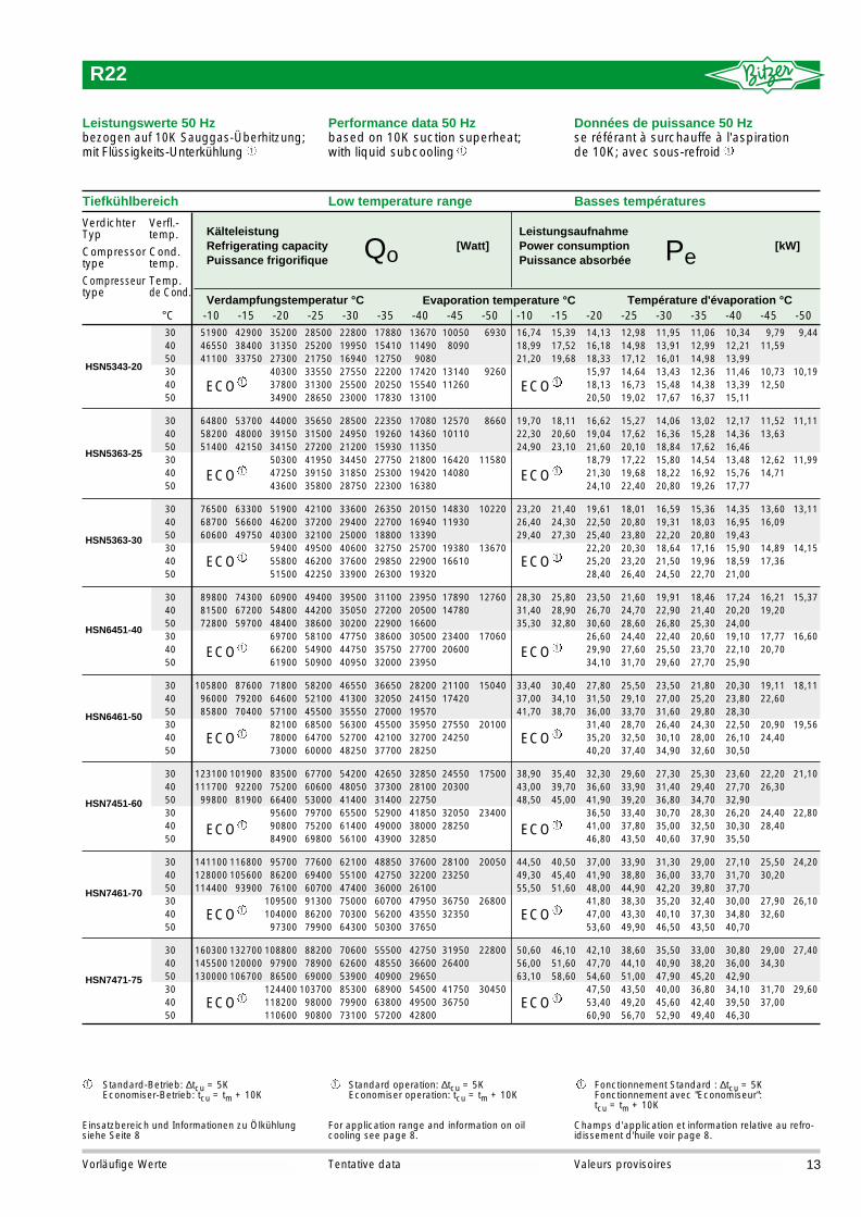
R22
Leistungsdaten und Einsatzbereiche für Economiser-Betrieb auf Anfrage
Einsatzbereich und Informationen zu Ölkühlungsiehe Seite 8
Performance data and application ranges for Economiser operation upon request
For application range and information on oil cooling see page 8.
Données de puissance et champs d'applicationpour une operation avec économiseur surdemande
Champs d'application et information relative au refro-idissement d'huile voir page 8.
1 1 1
1 1 1
12 Valeurs provisoiresTentative dataVorläufige Werte
51900 42900 35200 28500 22800 17880 13670 10050 6930 16,74 15,39 14,13 12,98 11,95 11,06 10,34 9,79 9,4446550 38400 31350 25200 19950 15410 11490 8090 18,99 17,52 16,18 14,98 13,91 12,99 12,21 11,5941100 33750 27300 21750 16940 12750 9080 21,20 19,68 18,33 17,12 16,01 14,98 13,99
40300 33550 27550 22200 17420 13140 9260 15,97 14,64 13,43 12,36 11,46 10,73 10,1937800 31300 25500 20250 15540 11260 18,13 16,73 15,48 14,38 13,39 12,5034900 28650 23000 17830 13100 20,50 19,02 17,67 16,37 15,11
64800 53700 44000 35650 28500 22350 17080 12570 8660 19,70 18,11 16,62 15,27 14,06 13,02 12,17 11,52 11,1158200 48000 39150 31500 24950 19260 14360 10110 22,30 20,60 19,04 17,62 16,36 15,28 14,36 13,6351400 42150 34150 27200 21200 15930 11350 24,90 23,10 21,60 20,10 18,84 17,62 16,46
50300 41950 34450 27750 21800 16420 11580 18,79 17,22 15,80 14,54 13,48 12,62 11,9947250 39150 31850 25300 19420 14080 21,30 19,68 18,22 16,92 15,76 14,7143600 35800 28750 22300 16380 24,10 22,40 20,80 19,26 17,77
76500 63300 51900 42100 33600 26350 20150 14830 10220 23,20 21,40 19,61 18,01 16,59 15,36 14,35 13,60 13,1168700 56600 46200 37200 29400 22700 16940 11930 26,40 24,30 22,50 20,80 19,31 18,03 16,95 16,0960600 49750 40300 32100 25000 18800 13390 29,40 27,30 25,40 23,80 22,20 20,80 19,43
59400 49500 40600 32750 25700 19380 13670 22,20 20,30 18,64 17,16 15,90 14,89 14,1555800 46200 37600 29850 22900 16610 25,20 23,20 21,50 19,96 18,59 17,3651500 42250 33900 26300 19320 28,40 26,40 24,50 22,70 21,00
89800 74300 60900 49400 39500 31100 23950 17890 12760 28,30 25,80 23,50 21,60 19,91 18,46 17,24 16,21 15,3781500 67200 54800 44200 35050 27200 20500 14780 31,40 28,90 26,70 24,70 22,90 21,40 20,20 19,2072800 59700 48400 38600 30200 22900 16600 35,30 32,80 30,60 28,60 26,80 25,30 24,00
69700 58100 47750 38600 30500 23400 17060 26,60 24,40 22,40 20,60 19,10 17,77 16,6066200 54900 44750 35750 27700 20600 29,90 27,60 25,50 23,70 22,10 20,7061900 50900 40950 32000 23950 34,10 31,70 29,60 27,70 25,90
105800 87600 71800 58200 46550 36650 28200 21100 15040 33,40 30,40 27,80 25,50 23,50 21,80 20,30 19,11 18,1196000 79200 64600 52100 41300 32050 24150 17420 37,00 34,10 31,50 29,10 27,00 25,20 23,80 22,6085800 70400 57100 45500 35550 27000 19570 41,70 38,70 36,00 33,70 31,60 29,80 28,30
82100 68500 56300 45500 35950 27550 20100 31,40 28,70 26,40 24,30 22,50 20,90 19,5678000 64700 52700 42100 32700 24250 35,20 32,50 30,10 28,00 26,10 24,4073000 60000 48250 37700 28250 40,20 37,40 34,90 32,60 30,50
123100 101900 83500 67700 54200 42650 32850 24550 17500 38,90 35,40 32,30 29,60 27,30 25,30 23,60 22,20 21,10111700 92200 75200 60600 48050 37300 28100 20300 43,00 39,70 36,60 33,90 31,40 29,40 27,70 26,3099800 81900 66400 53000 41400 31400 22750 48,50 45,00 41,90 39,20 36,80 34,70 32,90
95600 79700 65500 52900 41850 32050 23400 36,50 33,40 30,70 28,30 26,20 24,40 22,8090800 75200 61400 49000 38000 28250 41,00 37,80 35,00 32,50 30,30 28,4084900 69800 56100 43900 32850 46,80 43,50 40,60 37,90 35,50
141100 116800 95700 77600 62100 48850 37600 28100 20050 44,50 40,50 37,00 33,90 31,30 29,00 27,10 25,50 24,20128000 105600 86200 69400 55100 42750 32200 23250 49,30 45,40 41,90 38,80 36,00 33,70 31,70 30,20114400 93900 76100 60700 47400 36000 26100 55,50 51,60 48,00 44,90 42,20 39,80 37,70
109500 91300 75000 60700 47950 36750 26800 41,80 38,30 35,20 32,40 30,00 27,90 26,10104000 86200 70300 56200 43550 32350 47,00 43,30 40,10 37,30 34,80 32,6097300 79900 64300 50300 37650 53,60 49,90 46,50 43,50 40,70
160300 132700 108800 88200 70600 55500 42750 31950 22800 50,60 46,10 42,10 38,60 35,50 33,00 30,80 29,00 27,40145500 120000 97900 78900 62600 48550 36600 26400 56,00 51,60 47,70 44,10 40,90 38,20 36,00 34,30130000 106700 86500 69000 53900 40900 29650 63,10 58,60 54,60 51,00 47,90 45,20 42,90
124400 103700 85300 68900 54500 41750 30450 47,50 43,50 40,00 36,80 34,10 31,70 29,60118200 98000 79900 63800 49500 36750 53,40 49,20 45,60 42,40 39,50 37,00110600 90800 73100 57200 42800 60,90 56,70 52,90 49,40 46,30
Standard-Betrieb: ∆tcu = 5KEconomiser-Betrieb: tcu = tm + 10K
Einsatzbereich und Informationen zu Ölkühlungsiehe Seite 8
Standard operation: ∆tcu = 5KEconomiser operation: tcu = tm + 10K
For application range and information on oil cooling see page 8.
Fonctionnement Standard : ∆tcu = 5KFonctionnement avec "Economiseur": tcu = tm + 10K
Champs d'application et information relative au refro-idissement d'huile voir page 8.
1 1 1
HSN5343-20
HSN5363-25
HSN5363-30
HSN6451-40
HSN6461-50
HSN7451-60
HSN7461-70
HSN7471-75
Tiefkühlbereich
VerdichterTyp
Compressortype
Compresseur type
-10 -15 -20 -25 -30 -35 -40 -45 -50 -10 -15 -20 -25 -30 -35 -40 -45 -50
Verfl.-temp.
Cond.temp.
Temp. de Cond.
°C
Low temperature range Basses températures
Verdampfungstemperatur °C
KälteleistungRefrigerating capacityPuissance frigorifique
[Watt]Leistungsaufnahme Power consumptionPuissance absorbée
[kW]
Evaporation temperature °C Température d'évaporation °C
1ECO 1ECO
1ECO 1ECO
1ECO 1ECO
1ECO 1ECO
1ECO 1ECO
1ECO 1ECO
1ECO 1ECO
1ECO 1ECO
Leistungswerte 50 Hzbezogen auf 10K Sauggas-Überhitzung;mit Flüssigkeits-Unterkühlung
Performance data 50 Hzbased on 10K suction superheat; with liquid subcooling
Données de puissance 50 Hzse référant à surchauffe à l'aspirationde 10K; avec sous-refroid
304050304050
304050304050
304050304050
304050304050
304050304050
304050304050
304050304050
304050304050
R22
Qo Pe
1 1 1
13Valeurs provisoiresTentative dataVorläufige Werte

Leistungs-regelung
Capacitycontrol
Régulateurde puiss.
%
Strom-art
Electricalsupply
Genredecourant
RohranschlüsseDruckleitung Saugleitungmm Zoll mm Zoll
Pipe connectionsDischarge line Suction linemm inch mm inch
RaccordsConduite de refoul. Conduite d’aspir.
mm pouce mm pouce
Technische Daten Technical data Caractéristiques techniques
Nominalleistung ist nicht identisch mit dermax. Motorleistung. Für die Auslegung vonSchützen, Zuleitungen und Sicherungenmax. Betriebsstrom bzw. max. Leistungs-aufnahme berücksichtigen.
bei 2900 min-1 (50 Hz) /bei 3500 min-1 (60 Hz)
Effektive Leistungsstufen sind von denBetriebsbedingungen abhängigK-Modelle -10/45°C (ohne ECO)N-Modelle -35/40°C (ohne ECO)
Andere Spannungen und Stromarten auf Anfrage
1
2
4
3
43
Nominal power is not the same as maximum motor power. For the selection of contactors, cables and fuses the max. working current/max. power consumption must be considered
with 2900 min-1 (50 Hz) /with 3500 min-1 (60 Hz)
Effective capacity stages are dependent upon operating conditionsK-Modelle -10/45°C (without ECO)N-Modelle -35/40°C (withoutECO)
For other electrical supplies upon request
1
2
4
3
La puissance nominale n’est pas iden-tique à la puissance max. du moteur. Pour la sélection des contacteurs, des câbles d’alimentation et des fusibles, tenir compte du courant de service max. / de la puissance absorbée max.
à 2900 min-1 (50 Hz) /à 3500 min-1 (60 Hz)
Les étages de puissance effectifs dépen-dent des conditions de fonctionnement.K-Modelle -10/45°C (sans ECO)N-Modelle -35/40°C (sans ECO)
Autres tensions et types de courant sur demande
1
2
4
3
Verdichter-Typ
Compressortype
Compresseurtype
MotorNominal
MotorNominal
MoteurNominal
kW
Förder-volumen50 Hz
Displa-cement50 Hz
Volumebalayé50 Hz
m3/h
Gewicht
Weight
Poids
kg
max.Betriebsstrom
max.workingcurrent
Courantmax. enservice
A
max.Leistungsaufnahme
max.powerconsum.
Puissanceabsorbéemax.
kW
Anlauf-strom
Startingcurrent
Courantde dé-marrage
A Y/YY
HSK5343-30
HSN5343-20
HSK5353-35
HSN5353-25
HSK5363-40
HSN5363-30
HSK6451-50
HSN6451-40
HSK6461-60
HSK6461-50
HSK7451-70
HSN7451-60
HSK7461-80
HSN7461-70
HSK7471-90
HSN7471-75
HSKB6451-40
HSKB6461-40
HSKB7451-40
HSKB7461-40
HSKB7471-50
22
18.5
26
22
30
22
37
30
44
37
52
44
60
52
66
55
30
30
30
30
37
170
166
178
169
183
174
238
234
246
238
305
297
314
310
336
326
234
234
285
290
310
84
100
118
140
165
192
220
250
140
165
192
220
250
Förder-volumen60 Hz
Displa-cement60 Hz
Volumebalayé60 Hz
m3/h
101
121
142
168
198
232
266
302
168
198
232
266
302
42 15/8“
42 15/8“
42 15/8“
42 15/8“
42 15/8“
54 21/8“
54 21/8“
54 21/8“
42 15/8“
54 21/8“
54 21/8“
54 21/8“
54 21/8“
54 21/8“
54 21/8“
54 21/8“
76 31/8“
76 31/8“
76 31/8“
54 21/8“
76 31/8“
76 31/8“
100
75
50
47
37
56
44
65
50
79
65
98
79
124
98
144
124
162
144
65
65
79
31
24
36
28
42
32
50
40
65
50
75
65
85
75
92
85
40
40
50
75/218
62/201
92/266
75/218
109/311
92/266
206/355
187/313
267/449
206/355
290/485
267/449
350/585
290/485
423/686
350/585
187/313
187/313
206/355
100/90/70
100/85/55
100/85/60
100/80/45
100/75/50
100/70/40
➡➡
Boo
ster
1 2 2
14
400
V ±
10%
Y/Y
Y–3
–50H
z46
0 V
±10
% Y
/YY
–3–6
0Hz
Par
t Win
ding
DL
SL CR2
4M26x1,5
9M10
5
K1
360
305
526
A
50
158K2
F360E
112
239
233
202
324
71
ø17
407
190
88
1520
661 1/4''-12 UNF
1/8''-27 NPTF2 (LP)
1/8''-27 NPTF
1 (HP)1/8''-27 NPTF
3 (HP)
1/8''-27 NPTF
6
CR112
9
363
1/4"-18 NPTF71 (HP) 2 (LP)
3M26x1,5
4
DLSL1/8"-27 NPTF 1/4"-18 NPTF
CR2CR1
61/8"-27 NPTF
96
26
439
315
2754040183
400 141
221
282
143
59
765
179
148
370
5
8
ø21
DL
41/8"-27 NPTF
2 (LP)CR2SL
1/8"-27 NPTF1 (HP)
5
1/8"-27 NPTF 3 (HP)
1/8"-27 NPTF6
1 1/4"-12 UNF
71
10150
916
55
50
121 305
360
508
170 283
184 129
286
ø17
190
418
105
190
2030
M26x1,59
M10CR1
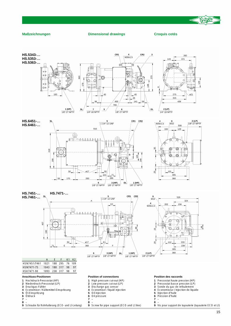
Maßzeichnungen
HS.7451-… HS.7471-…HS.7461-…
HS.6451-…HS.6461-…
HS.5343-…HS.5353-…HS.5363-…
Dimensional drawings Croquis cotés
15
Anschluss-Positionen1 Hochdruck-Pressostat (HP)2 Niederdruck-Pressostat (LP)3 Druckgas-Fühler4 Economiser / Kältemittel-Einspritzung5 Öl-Einspritzung6 Öldruck7 –8 –9 Schraube für Rohrhalterung (ECO- und LI-Leitung)
Position of connections1 High pressure cut-out (HP)2 Low pressure cut-out (LP)3 Discharge gas sensor4 Economiser / liquid injection5 Oil injection6 Oil pressure7 –8 –9 Screw for pipe support (ECO and LI line)
Position des raccords1 Pressostat haute pression (HP)2 Pressostat basse pression (LP)3 Sonde du gaz de refoulement4 Economiseur / injection de liquide5 Injection d’huile6 Pression d’huile7 –8 –9 Vis pour support de tuyauterie (tuyauterie ECO et Ll)
HSN7451/7461HSN7471-75HSK7471-90
102110431093
188188238
295317317
769898
A E F K11099797
K2

Änd
erun
gen
vorb
ehal
ten
/ Sub
ject
to c
hang
e / T
oute
s m
odifi
catio
ns r
ésér
vées
09.
00
Bitzer Kühlmaschinenbau GmbHP. O. Box 240
D-71044 Sindelfingen (Germany)Tel. +49(0)7031/932-0
Fax +49(0)7031/932-146+147http://www.bitzer.de • [email protected]