Embed Size (px)
Citation preview
ww
w.in
l.g
ov
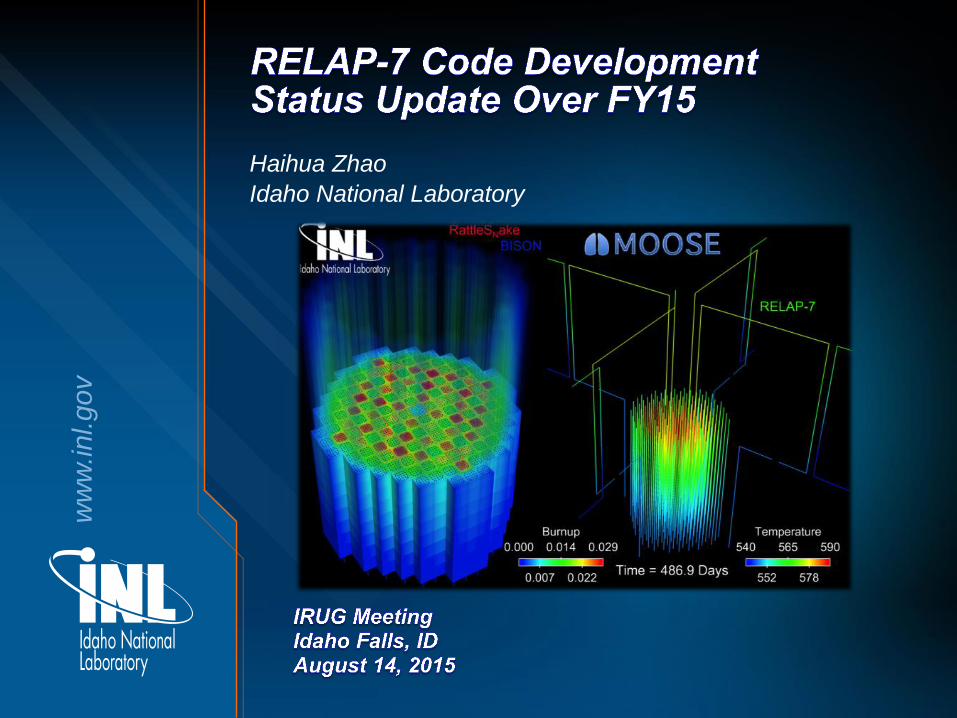
Haihua Zhao
Idaho National Laboratory

RELAP-7 Overview
• RELAP-7 is a project sponsored by US DOE to develop a new reactor system analysis code.
• RELAP-7 code is based on INL’s MOOSE (Multi-Physics Object-Oriented Simulation Environment) framework.
• RELAP-7 code mainly uses 0-D and 1-D models to simulate thermal hydraulics problems at system level.
• Additional capabilities and physics can be obtained by coupling with other MOOSE-based applications:
– RAVEN (GUI, UQ, and risk packages)
– RattleSnake (3-D neutron diffusion and transport code)
– BISON (3-D transient fuel performance code)
2

RELAP-7 Components
• Physical components are basic units: – A model is composed of a 3-D
network of 1-D physical components connected by 0-D components.
• There are three main types of components in RELAP-7:
– 1-D components, such as pipe, heat exchanger, and core channel, describe 1-D fluid flow model and additional heat conduction model.
– 0-D components for setting boundary conditions (BC).
– 0-D components describing special physics and connecting 1-D components.
– Additional models include 0-D point kinetics model, sub-channel model, etc.
A Simplified PWR model
Steady state result shown by
RAVEN GUI. 3
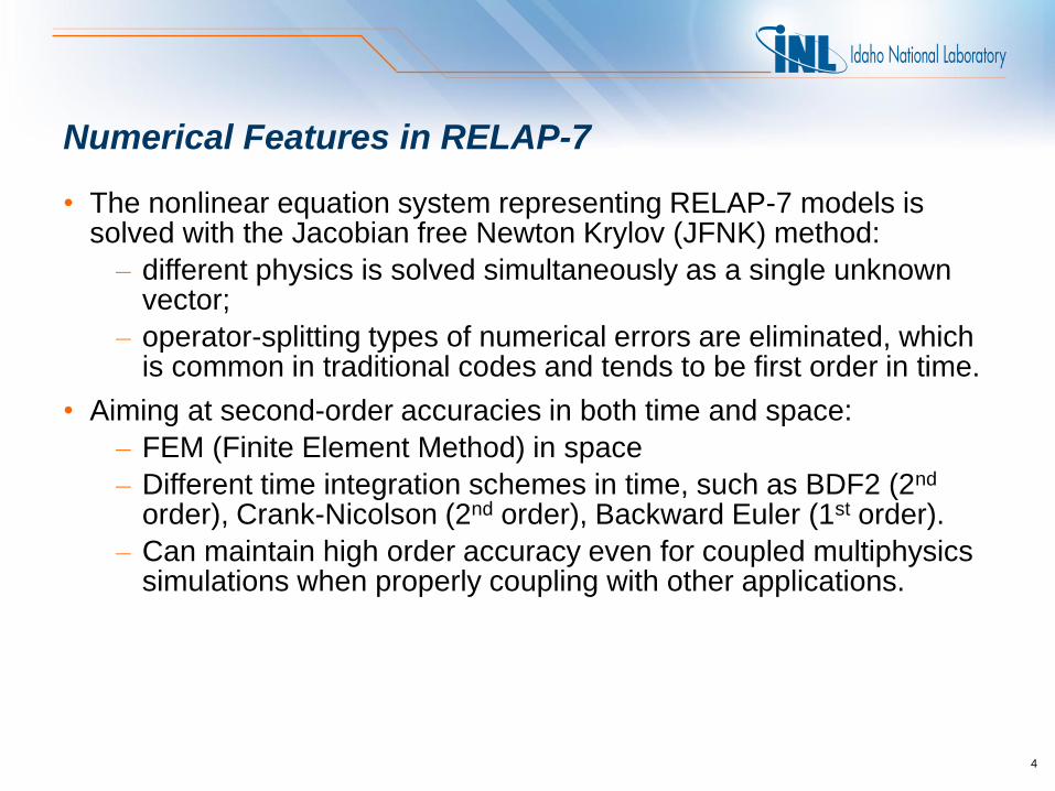
Numerical Features in RELAP-7
• The nonlinear equation system representing RELAP-7 models is solved with the Jacobian free Newton Krylov (JFNK) method:
– different physics is solved simultaneously as a single unknown vector;
– operator-splitting types of numerical errors are eliminated, which is common in traditional codes and tends to be first order in time.
• Aiming at second-order accuracies in both time and space:
– FEM (Finite Element Method) in space
– Different time integration schemes in time, such as BDF2 (2nd order), Crank-Nicolson (2nd order), Backward Euler (1st order).
– Can maintain high order accuracy even for coupled multiphysics simulations when properly coupling with other applications.
4

RELAP-7 Timeline
FY 2012 FY 2013 FY 2014 FY 2015 and beyond
Demonstration of a steady state PWR simulation
BWR SBO simulation on simplified system with relevant components
- Initial beta release
- Refined BWR SBO
- Comprehensive Verification & Validation (V&V) & Uncertainty Quantification (UQ)
- Delivering a large set of validating benchmarks
- 3 equation single phase - Heat structures - Basic components
-HEM & 7 equation two phase flow - Additional relevant components and physics for SBO
- Develop the full set of components to perform SBO for a BWR - Prepare the code for the initial beta release
- Develop and upgrade closure laws. Improve physical modeling of equation parameters - Extend the number of available components
5

Some Activities in the Past Year
• Adding IAPWS95 water/steam properties and interfaces
• Adding two phase closure models into two-pressure 7-Eq model
• Developing new components, such as accumulator and pressurizer
• Enabling preliminary coupling between RELAP-7, BISON and RattleSnake
• Performing system level numerical verification for a single phase loop
• Refining BWR SBO simulation
• Improving code software structures
6

Activity example 1: developing Accumulator component
7

8
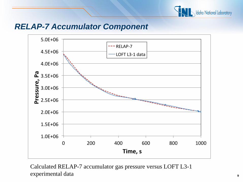
RELAP-7 Accumulator Component
• A new RELAP-7 Accumulator component has been developed recently:
Similar physical models as RELAP5
Including 30 equations describing
Mass, energy, and momentum conservations
Heat and mass transfer processes
Two shapes of tank: cylinder or sphere
Fully implicit 2nd order numerical method
• The model has been validated with LOFT experimental data (thanks to Paul Bayless for the data and test case).
Typical cylindrical accumulator (RELAP5/3D)
8
Steam and nitrogen
P
Tg
Liquid water
Tf
DzL
LfTK
LgTK
LL AL
ATK
vfL
vgL Pexit
g
QD
Typical spherical accumulator (RELAP5/3D)
9
RELAP-7 Accumulator Component
9
1.0E+06
1.5E+06
2.0E+06
2.5E+06
3.0E+06
3.5E+06
4.0E+06
4.5E+06
5.0E+06
0 200 400 600 800 1000
Pressure,P
a
Time,s
RELAP-7
LOFTL3-1data
Calculated RELAP-7 accumulator gas pressure versus LOFT L3-1
experimental data

10
RELAP-7 Accumulator Component
10
Calculated RELAP-7 accumulator water level versus LOFT L3-1
experimental data
Activity example 2: numerical verification of a single
phase nature circulation loop
11
Publications:
1. H. Zhao, L. Zou, H. Zhang, R. Martineau, “Numerical Verification of The RELAP-7 Core Channel
Single-Phase Model,” Proceedings of International Topical Meeting on Advances in Thermal
Hydraulics - 2014 (ATH '14), Reno, NV, USA, June 15-19, 2014.
2. H. Zhao, L. Zou, H. Zhang, R. Martineau, “Numerical Verification of RELAP-7 Model for a
Single Phase Natural Circulation Loop,” Vol. 112, 2015.
12
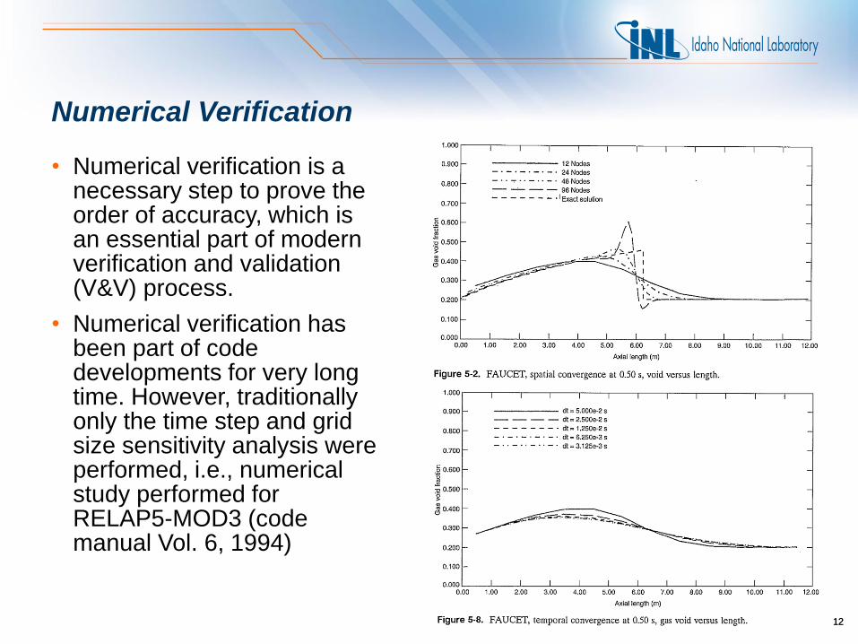
Numerical Verification
• Numerical verification is a necessary step to prove the order of accuracy, which is an essential part of modern verification and validation (V&V) process.
• Numerical verification has been part of code developments for very long time. However, traditionally only the time step and grid size sensitivity analysis were performed, i.e., numerical study performed for RELAP5-MOD3 (code manual Vol. 6, 1994)
12

13
Numerical Verification Cont.
• Numerical verification can be performed in a further step by calculating the convergence rates of the time integration scheme and spatial discretizing method.
• Strict numerical verification process is a very effective way to eliminate code bugs, which cause lower order errors, i.e.
– boundary condition errors,
– coupling errors often cause 0th order or 1st order errors.
• We have performed numerical verification work for the single phase core channel component model for both steady state and transient cases and verified the 2nd order accuracy in both time and space.
13
Spatial Convergence Study for Steady State Fuel
Pin Temperature
y=1.E+03x-2.E+001
10
100
2 4 8 16 32
Fueltemperatureabsoluteerrornorm
,K
Numberoffuelpinelements
Calculatederror
Trendline
14
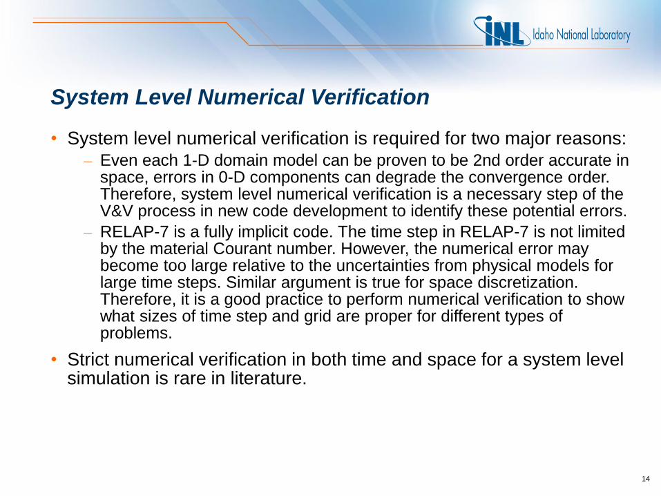
System Level Numerical Verification
• System level numerical verification is required for two major reasons: – Even each 1-D domain model can be proven to be 2nd order accurate in
space, errors in 0-D components can degrade the convergence order. Therefore, system level numerical verification is a necessary step of the V&V process in new code development to identify these potential errors.
– RELAP-7 is a fully implicit code. The time step in RELAP-7 is not limited by the material Courant number. However, the numerical error may become too large relative to the uncertainties from physical models for large time steps. Similar argument is true for space discretization. Therefore, it is a good practice to perform numerical verification to show what sizes of time step and grid are proper for different types of problems.
• Strict numerical verification in both time and space for a system level simulation is rare in literature.

15
Single Phase Natural Circulation Loop Model
• The loop is an imaginary scaled experiment with typical PWR 2 × 2 fuel rods as the heated section and a tube-shell type counter-current heat exchanger (HX) as the cooler section.
• The power is about 1% of the full power of the 4 fuel rods to simulate the typical decay heat.
• Same wall friction and heat transfer correlations from RELAP5 are used for the primary side. A very large number is used for the HX secondary heat transfer coefficient to simulate boiling heat transfer.
15
Schematic of the natural circulation loop
problem.

16
Peak Clad Temperature During the Transient
16

17
Mass Flow Rate Through the Core Channel During the Transient
17

18
Numerical Verification Method
• We only run the simulations to 200 s for the numerical verification work with several reasons:
– long enough to show accumulated time integration error;
– short enough to avoid the spatial error dominated by time effect;
– low simulation costs.
• Since it is almost impossible to derive an analytical solution for the problem, we use the solution with a very small time step (0.025 s) and a very small grid size (about 0.09 m) as the reference result to calculate numerical errors.
• Since the average mass flow rate through the core channel is the most important figure of merit (FOM) for natural circulation, we use it for numerical verification.

19
Spatial Convergence Rate for Mass Flow Rate
19
y=7.10E-03x1.91E+00
1.0E-04
1.0E-03
1.0E-02
1.0E-01
0.1 1 10
Rela
veErrorofMassFlowRate
Averageelementsize,m
MassFlowRate
Power(MassFlowRate)

20
Time Step Convergence Rate for Mass Flow Rate
20
y=9.07E-01x2.57E+00
1.0E-05
1.0E-04
1.0E-03
1.0E-02
1.0E-01
0.01 0.1 1 10
Rela
veErrorofMassFlowRate
TimeStep,[s]
MassFlowRate
Power(MassFlowRate)
Activity example 3: refined BWR SBO simulation
21
Publications:
1. H. Zhao, L. Zou, H. Zhang, R. Martineau, “A Strongly Coupled Reactor Core Isolation Cooling System
Model for Extended Station Black-Out Analyses,” Proceedings of the 16th International Topical Meeting on
Nuclear Reactor Thermal Hydraulics (NURETH-16), Hyatt Regency Chicago, USA, August 30-September
4, 2015.
2. H. Zhao, H. Zhang, L. Zou, D. Andrs, R. Martineau, “Demonstration of Fully Coupled Simplified Extended
Station Black-Out Accident Simulation with RELAP-7,” Proceedings of PHYSOR 2014 – The Role of
Reactor Physics Toward a Sustainable Future, Kyoto, Japan, September 28 – October 3, 2014.

Schematics of A Boiling Water Reactor Plant System Model for SBO Simulation
22

Simulation Results for Down Comer Water Level and RCIC Mass Flow Rates Through Turbine and Pump
23

Simulation Results for Mass Flow Rate Through SRVs and Dome Pressure
24
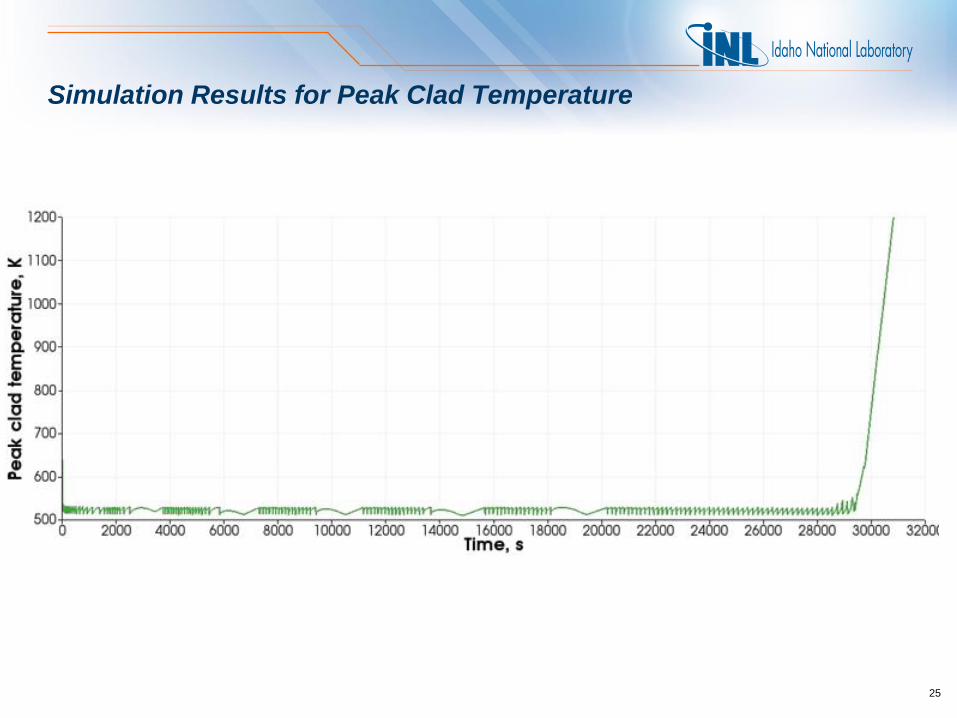
Simulation Results for Peak Clad Temperature
25

Summary
• The Beta release in December 2014 concludes the first stage of RELAP-7 development work which focused on establishing software framework, demonstration of fully implicit high order numerical methods and basic two phase flow models without complex closure models.
• The next stage of work will be more challenging:
– focus on putting specific models and two phase closure models from RELAP5, TRAC ,and TRACE into the code;
– Optimization of numerical methods;
– Verification and validation with SETs, component tests, and IETs.
26

BACKUP SLIDES
27

28
Mass Flow Rate Undershoot Problem
• This issue can be resolved by reducing the time step or by using the more stable first order Backward Euler method.
• This case reveals the complexity of performing time step convergence study for a complex system. The system has different physical time scale at different stages. Therefore, it is better to allow variable time step to follow the physics.
28
Mass flow rate undershoot problem for
larger time step