Embed Size (px)
Citation preview
Norman Hendrich
HADES Tutorial
version 0.90 — 15. Juli 2002

Contact:
University of HamburgDept. Computer ScienceNorman HendrichVogt-Koelln-Str. 30D-22527 HamburgGermany
version 0.9015. Juli 2002
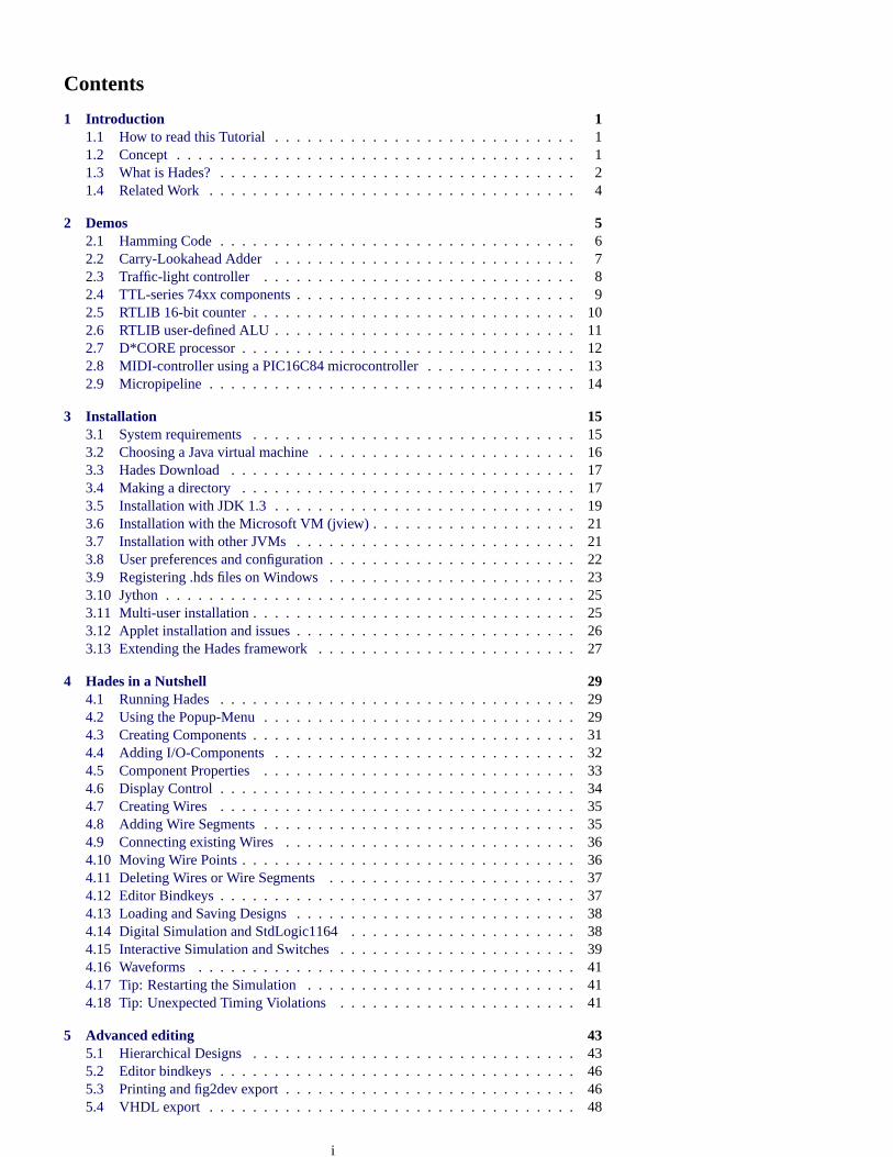
Contents
1 Introduction 11.1 How to read this Tutorial. . . . . . . . . . . . . . . . . . . . . . . . . . . . 11.2 Concept. . . . . . . . . . . . . . . . . . . . . . . . . . . . . . . . . . . . . 11.3 What is Hades?. . . . . . . . . . . . . . . . . . . . . . . . . . . . . . . . . 21.4 Related Work. . . . . . . . . . . . . . . . . . . . . . . . . . . . . . . . . . 4
2 Demos 52.1 Hamming Code. . . . . . . . . . . . . . . . . . . . . . . . . . . . . . . . . 62.2 Carry-Lookahead Adder. . . . . . . . . . . . . . . . . . . . . . . . . . . . 72.3 Traffic-light controller . . . . . . . . . . . . . . . . . . . . . . . . . . . . . 82.4 TTL-series 74xx components. . . . . . . . . . . . . . . . . . . . . . . . . . 92.5 RTLIB 16-bit counter. . . . . . . . . . . . . . . . . . . . . . . . . . . . . . 102.6 RTLIB user-defined ALU. . . . . . . . . . . . . . . . . . . . . . . . . . . . 112.7 D*CORE processor. . . . . . . . . . . . . . . . . . . . . . . . . . . . . . . 122.8 MIDI-controller using a PIC16C84 microcontroller. . . . . . . . . . . . . . 132.9 Micropipeline . . . . . . . . . . . . . . . . . . . . . . . . . . . . . . . . . .14
3 Installation 153.1 System requirements. . . . . . . . . . . . . . . . . . . . . . . . . . . . . . 153.2 Choosing a Java virtual machine. . . . . . . . . . . . . . . . . . . . . . . . 163.3 Hades Download. . . . . . . . . . . . . . . . . . . . . . . . . . . . . . . .173.4 Making a directory . . . . . . . . . . . . . . . . . . . . . . . . . . . . . . . 173.5 Installation with JDK 1.3. . . . . . . . . . . . . . . . . . . . . . . . . . . . 193.6 Installation with the Microsoft VM (jview). . . . . . . . . . . . . . . . . . . 213.7 Installation with other JVMs. . . . . . . . . . . . . . . . . . . . . . . . . . 213.8 User preferences and configuration. . . . . . . . . . . . . . . . . . . . . . . 223.9 Registering .hds files on Windows. . . . . . . . . . . . . . . . . . . . . . . 233.10 Jython. . . . . . . . . . . . . . . . . . . . . . . . . . . . . . . . . . . . . .253.11 Multi-user installation. . . . . . . . . . . . . . . . . . . . . . . . . . . . . . 253.12 Applet installation and issues. . . . . . . . . . . . . . . . . . . . . . . . . . 263.13 Extending the Hades framework. . . . . . . . . . . . . . . . . . . . . . . . 27
4 Hades in a Nutshell 294.1 Running Hades. . . . . . . . . . . . . . . . . . . . . . . . . . . . . . . . .294.2 Using the Popup-Menu. . . . . . . . . . . . . . . . . . . . . . . . . . . . . 294.3 Creating Components. . . . . . . . . . . . . . . . . . . . . . . . . . . . . . 314.4 Adding I/O-Components. . . . . . . . . . . . . . . . . . . . . . . . . . . . 324.5 Component Properties. . . . . . . . . . . . . . . . . . . . . . . . . . . . . 334.6 Display Control. . . . . . . . . . . . . . . . . . . . . . . . . . . . . . . . .344.7 Creating Wires . . . . . . . . . . . . . . . . . . . . . . . . . . . . . . . . .354.8 Adding Wire Segments. . . . . . . . . . . . . . . . . . . . . . . . . . . . . 354.9 Connecting existing Wires. . . . . . . . . . . . . . . . . . . . . . . . . . . 364.10 Moving Wire Points. . . . . . . . . . . . . . . . . . . . . . . . . . . . . . . 364.11 Deleting Wires or Wire Segments. . . . . . . . . . . . . . . . . . . . . . . 374.12 Editor Bindkeys. . . . . . . . . . . . . . . . . . . . . . . . . . . . . . . . .374.13 Loading and Saving Designs. . . . . . . . . . . . . . . . . . . . . . . . . . 384.14 Digital Simulation and StdLogic1164. . . . . . . . . . . . . . . . . . . . . 384.15 Interactive Simulation and Switches. . . . . . . . . . . . . . . . . . . . . . 394.16 Waveforms . . . . . . . . . . . . . . . . . . . . . . . . . . . . . . . . . . .414.17 Tip: Restarting the Simulation. . . . . . . . . . . . . . . . . . . . . . . . . 414.18 Tip: Unexpected Timing Violations. . . . . . . . . . . . . . . . . . . . . . 41
5 Advanced editing 435.1 Hierarchical Designs. . . . . . . . . . . . . . . . . . . . . . . . . . . . . . 435.2 Editor bindkeys. . . . . . . . . . . . . . . . . . . . . . . . . . . . . . . . .465.3 Printing and fig2dev export. . . . . . . . . . . . . . . . . . . . . . . . . . . 465.4 VHDL export . . . . . . . . . . . . . . . . . . . . . . . . . . . . . . . . . .48
i
6 Waveforms 516.1 Waveform types. . . . . . . . . . . . . . . . . . . . . . . . . . . . . . . . .526.2 Using the waveform viewer. . . . . . . . . . . . . . . . . . . . . . . . . . . 526.3 Searching waveform data. . . . . . . . . . . . . . . . . . . . . . . . . . . . 536.4 Saving and loading waveform data. . . . . . . . . . . . . . . . . . . . . . . 536.5 Scripting. . . . . . . . . . . . . . . . . . . . . . . . . . . . . . . . . . . . .54
7 Model libraries 557.1 Model library organization. . . . . . . . . . . . . . . . . . . . . . . . . . . 557.2 Browsing and accessing simulation components. . . . . . . . . . . . . . . . 557.3 Colibri Browser. . . . . . . . . . . . . . . . . . . . . . . . . . . . . . . . .567.4 Label component. . . . . . . . . . . . . . . . . . . . . . . . . . . . . . . .567.5 Interactive I/O. . . . . . . . . . . . . . . . . . . . . . . . . . . . . . . . . .577.6 VCC, GND, Pullup . . . . . . . . . . . . . . . . . . . . . . . . . . . . . . . 587.7 Basic and complex logic gates. . . . . . . . . . . . . . . . . . . . . . . . . 587.8 Flipflops. . . . . . . . . . . . . . . . . . . . . . . . . . . . . . . . . . . . .597.9 Register. . . . . . . . . . . . . . . . . . . . . . . . . . . . . . . . . . . . .597.10 ROM . . . . . . . . . . . . . . . . . . . . . . . . . . . . . . . . . . . . . .597.11 RTLIB . . . . . . . . . . . . . . . . . . . . . . . . . . . . . . . . . . . . . .617.12 TTL 74xx series models. . . . . . . . . . . . . . . . . . . . . . . . . . . . 637.13 System-level components. . . . . . . . . . . . . . . . . . . . . . . . . . . . 637.14 PIC 16C84 microcontroller. . . . . . . . . . . . . . . . . . . . . . . . . . . 647.15 MIPS IDT R3051 core. . . . . . . . . . . . . . . . . . . . . . . . . . . . . 64
8 Scripting and Stimuli 658.1 Java-written scripts. . . . . . . . . . . . . . . . . . . . . . . . . . . . . . . 658.2 Batch-mode simulation and circuit selftests. . . . . . . . . . . . . . . . . . 678.3 Jython. . . . . . . . . . . . . . . . . . . . . . . . . . . . . . . . . . . . . .708.4 Generating simulation stimuli. . . . . . . . . . . . . . . . . . . . . . . . . . 718.5 Stimuli files and class StimuliParser. . . . . . . . . . . . . . . . . . . . . . 73
9 Writing Components 759.1 Overview and Architecture. . . . . . . . . . . . . . . . . . . . . . . . . . . 759.2 Simulation Overview. . . . . . . . . . . . . . . . . . . . . . . . . . . . . . 779.3 Graphics: Static Symbols. . . . . . . . . . . . . . . . . . . . . . . . . . . . 809.4 A Simple Example: Basic AND2 Gate. . . . . . . . . . . . . . . . . . . . . 829.5 A D-Flipflop. . . . . . . . . . . . . . . . . . . . . . . . . . . . . . . . . . .869.6 Wakeup-Events: The Clock Generator. . . . . . . . . . . . . . . . . . . . . 879.7 Dynamic Symbols and Animation. . . . . . . . . . . . . . . . . . . . . . . 909.8 PropertySheet and SimObject User Interfaces. . . . . . . . . . . . . . . . . 929.9 Assignable. . . . . . . . . . . . . . . . . . . . . . . . . . . . . . . . . . . .949.10 DesignManager. . . . . . . . . . . . . . . . . . . . . . . . . . . . . . . . .949.11 DesignHierarchyNavigator. . . . . . . . . . . . . . . . . . . . . . . . . . . 95
10 FAQ, tips and tricks 9710.1 Frequently asked questions. . . . . . . . . . . . . . . . . . . . . . . . . . . 97
10.1.1 The documentation is wrong?. . . . . . . . . . . . . . . . . . . . . 9710.1.2 The editor hangs?. . . . . . . . . . . . . . . . . . . . . . . . . . . . 9710.1.3 The popup menu is dead. . . . . . . . . . . . . . . . . . . . . . . . 9710.1.4 How do I cancel a command?. . . . . . . . . . . . . . . . . . . . . 9710.1.5 I can’t get it running . . . . . . . . . . . . . . . . . . . . . . . . . . 9710.1.6 How to check whether my hades.jar archive is broken?. . . . . . . . 9810.1.7 I get a ClassNotFoundError. . . . . . . . . . . . . . . . . . . . . . 9810.1.8 The editor starts, but I cannot load design files. . . . . . . . . . . . 9810.1.9 The Java virtual machine crashes. . . . . . . . . . . . . . . . . . . . 9810.1.10 The editor crashes. . . . . . . . . . . . . . . . . . . . . . . . . . . 9910.1.11 I cannot double-click the hades.jar archive. . . . . . . . . . . . . . . 9910.1.12 I got an OutOfMemoryError. . . . . . . . . . . . . . . . . . . . . . 9910.1.13 What are those editor messages?. . . . . . . . . . . . . . . . . . . .10010.1.14 Missing components after loading a design. . . . . . . . . . . . . .100
ii
10.1.15 Editor prints hundreds of messages while loading. . . . . . . . . . . 10010.1.16 Something strange happened right now. . . . . . . . . . . . . . . .10010.1.17 ghost components, ghost signals. . . . . . . . . . . . . . . . . . . .10010.1.18 How can I disable the tooltips?. . . . . . . . . . . . . . . . . . . . .10010.1.19 Why is this object off-grid? Why won’t the cursor snap to the object?10110.1.20 Why can’t I connect a wire to this port?. . . . . . . . . . . . . . . .10110.1.21 Hades won’t let me delete an object. . . . . . . . . . . . . . . . . .10110.1.22 Why don’t the bindkeys work?. . . . . . . . . . . . . . . . . . . . .10110.1.23 I get timing violations from my flipflops. . . . . . . . . . . . . . . .10110.1.24 Why won’t the editor accept to rename a component/signal?. . . . . 10110.1.25 Why doesn’t the cursor represent the editor state?. . . . . . . . . . . 10110.1.26 Operation X is slow . . . . . . . . . . . . . . . . . . . . . . . . . .10110.1.27 Remote X11-Display is very slow. . . . . . . . . . . . . . . . . . .10110.1.28 The simulation is suddenly very slow. . . . . . . . . . . . . . . . .10210.1.29 GND, VCC, and Pullup components do not work. . . . . . . . . . . 10210.1.30 The simulator reports undefined values. . . . . . . . . . . . . . . .10210.1.31 How can I automatically restore editor settings?. . . . . . . . . . . . 10310.1.32 My waveforms get overwritten?. . . . . . . . . . . . . . . . . . . .10310.1.33 How can I edit a SimObject symbol?. . . . . . . . . . . . . . . . .103
10.2 Tips and tricks. . . . . . . . . . . . . . . . . . . . . . . . . . . . . . . . . .10310.2.1 What other programs are in hades.jar? How to run them?. . . . . . . 10310.2.2 User-settings in .hadesrc. . . . . . . . . . . . . . . . . . . . . . . .10410.2.3 How to enable or disable glow-mode for individual signals?. . . . . 10410.2.4 What can I do to debug my circuits?. . . . . . . . . . . . . . . . . .10410.2.5 I need a two-phase clock. . . . . . . . . . . . . . . . . . . . . . . .10410.2.6 How can I print my circuit schematics?. . . . . . . . . . . . . . . .10410.2.7 Printing problems. . . . . . . . . . . . . . . . . . . . . . . . . . . .10510.2.8 How can I export my circuit schematics via fig2dev?. . . . . . . . . 10510.2.9 I cannot initialize my circuit. . . . . . . . . . . . . . . . . . . . . .10510.2.10 Simulation does not appear deterministic. . . . . . . . . . . . . . .10510.2.11 I took a schematic from a book, but the circuit does not work. . . . . 10510.2.12 VHDL export. . . . . . . . . . . . . . . . . . . . . . . . . . . . . .106
10.3 Known bugs and features. . . . . . . . . . . . . . . . . . . . . . . . . . . .10610.3.1 How should I report bugs?. . . . . . . . . . . . . . . . . . . . . . .10610.3.2 Spurious objects displayed. . . . . . . . . . . . . . . . . . . . . . .10610.3.3 Repaint algorithm . . . . . . . . . . . . . . . . . . . . . . . . . . .10710.3.4 Repaint bugs, DirectDraw. . . . . . . . . . . . . . . . . . . . . . .10710.3.5 How to get rid of an unconnected signal?. . . . . . . . . . . . . . .10710.3.6 The ’run for’ simulator command may deadlock. . . . . . . . . . . . 107
Bibliography 109
A SetupManager properties 110A.1 Hades properties. . . . . . . . . . . . . . . . . . . . . . . . . . . . . . . .110A.2 jfig default properties. . . . . . . . . . . . . . . . . . . . . . . . . . . . . .113
B Index 115
iii
List of Figures
1 DCF77 radio controlled clock . . . . . . . . . . . . . . . . . . . . . . . . . 22 Hades software architecture. . . . . . . . . . . . . . . . . . . . . . . . . . . 33 Hamming code demonstration. . . . . . . . . . . . . . . . . . . . . . . . . 64 CLA adder . . . . . . . . . . . . . . . . . . . . . . . . . . . . . . . . . . . 75 Traffic-light controller . . . . . . . . . . . . . . . . . . . . . . . . . . . . . 86 TTL circuits . . . . . . . . . . . . . . . . . . . . . . . . . . . . . . . . . . . 97 RTLIB 16-bit counter. . . . . . . . . . . . . . . . . . . . . . . . . . . . . . 108 User-defined ALU . . . . . . . . . . . . . . . . . . . . . . . . . . . . . . . 119 D*CORE processor. . . . . . . . . . . . . . . . . . . . . . . . . . . . . . . 1210 MIDI controller with PIC16C84 microprocessor. . . . . . . . . . . . . . . . 1311 Micropipeline . . . . . . . . . . . . . . . . . . . . . . . . . . . . . . . . . .1412 Design directories (Linux). . . . . . . . . . . . . . . . . . . . . . . . . . . 1813 Design directories (Windows). . . . . . . . . . . . . . . . . . . . . . . . . 1914 Hades default properties. . . . . . . . . . . . . . . . . . . . . . . . . . . . 2315 Registering .hds as a new file type on Windows 98. . . . . . . . . . . . . . . 2416 Registering .hds as a new file type on Windows ME (German). . . . . . . . 2417 Editor popup menu. . . . . . . . . . . . . . . . . . . . . . . . . . . . . . . 3018 Creating a NAND2 gate. . . . . . . . . . . . . . . . . . . . . . . . . . . . . 3119 The D-latch components. . . . . . . . . . . . . . . . . . . . . . . . . . . . 3220 The clock generator with its property sheet. . . . . . . . . . . . . . . . . . . 3321 Selecting the magnetic grid. . . . . . . . . . . . . . . . . . . . . . . . . . . 3422 The D-latch with components and wires. . . . . . . . . . . . . . . . . . . . 3623 The stdlogic values and glow mode colors. . . . . . . . . . . . . . . . . . . 3924 The NOT and AND functions of the stdlogic system (IEEE 1164). . . . . . 3925 Interactive I/O components. . . . . . . . . . . . . . . . . . . . . . . . . . . 4026 D-Latch with probes . . . . . . . . . . . . . . . . . . . . . . . . . . . . . . 4127 1-bit adder. . . . . . . . . . . . . . . . . . . . . . . . . . . . . . . . . . . .4428 CLA block . . . . . . . . . . . . . . . . . . . . . . . . . . . . . . . . . . .4429 8-bit adder. . . . . . . . . . . . . . . . . . . . . . . . . . . . . . . . . . . .4530 Important bindkeys in Hades, sorted alphabetically. . . . . . . . . . . . . . 4731 Waveform viewer window . . . . . . . . . . . . . . . . . . . . . . . . . . . 5132 WaveStdLogicVector waveforms. . . . . . . . . . . . . . . . . . . . . . . . 5233 Colibri browser . . . . . . . . . . . . . . . . . . . . . . . . . . . . . . . . .5634 ROM with memory editor window. . . . . . . . . . . . . . . . . . . . . . . 6035 testbench for LFSR-based signature analysis. . . . . . . . . . . . . . . . . . 6836 Using StimuliGenerator to drive a D-latch circuit. . . . . . . . . . . . . . . 7337 Hades architecture overview. . . . . . . . . . . . . . . . . . . . . . . . . . 7538 simobject class hierarchy. . . . . . . . . . . . . . . . . . . . . . . . . . . . 7739 simulation kernel and events. . . . . . . . . . . . . . . . . . . . . . . . . . 7840 simulation event processing. . . . . . . . . . . . . . . . . . . . . . . . . . . 7941 simobject port and signal connections. . . . . . . . . . . . . . . . . . . . . 8042 package hades.symbols. . . . . . . . . . . . . . . . . . . . . . . . . . . . . 81
iv
1
1 Introduction
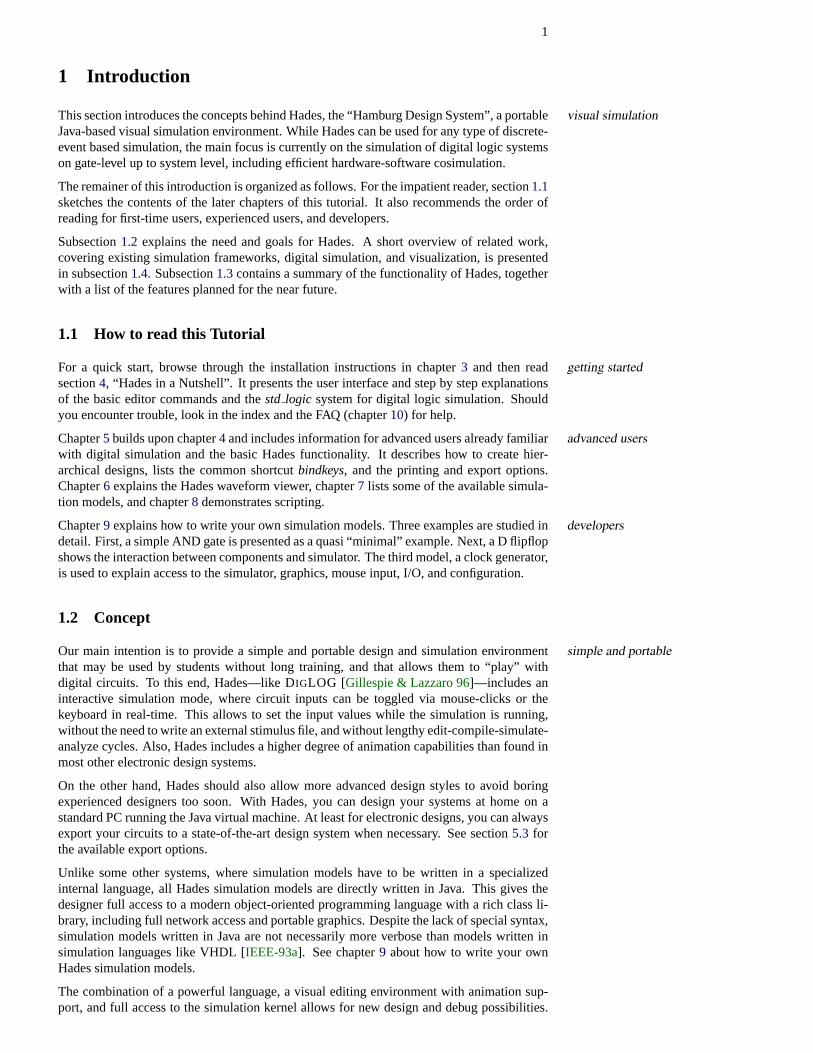
This section introduces the concepts behind Hades, the “Hamburg Design System”, a portablevisual simulationJava-based visual simulation environment. While Hades can be used for any type of discrete-event based simulation, the main focus is currently on the simulation of digital logic systemson gate-level up to system level, including efficient hardware-software cosimulation.
The remainer of this introduction is organized as follows. For the impatient reader, section1.1sketches the contents of the later chapters of this tutorial. It also recommends the order ofreading for first-time users, experienced users, and developers.
Subsection1.2 explains the need and goals for Hades. A short overview of related work,covering existing simulation frameworks, digital simulation, and visualization, is presentedin subsection1.4. Subsection1.3contains a summary of the functionality of Hades, togetherwith a list of the features planned for the near future.
1.1 How to read this Tutorial
For a quick start, browse through the installation instructions in chapter3 and then read getting startedsection4, “Hades in a Nutshell”. It presents the user interface and step by step explanationsof the basic editor commands and thestd logic system for digital logic simulation. Shouldyou encounter trouble, look in the index and the FAQ (chapter10) for help.
Chapter5 builds upon chapter4 and includes information for advanced users already familiaradvanced userswith digital simulation and the basic Hades functionality. It describes how to create hier-archical designs, lists the common shortcutbindkeys, and the printing and export options.Chapter6 explains the Hades waveform viewer, chapter7 lists some of the available simula-tion models, and chapter8 demonstrates scripting.
Chapter9 explains how to write your own simulation models. Three examples are studied indevelopersdetail. First, a simple AND gate is presented as a quasi “minimal” example. Next, a D flipflopshows the interaction between components and simulator. The third model, a clock generator,is used to explain access to the simulator, graphics, mouse input, I/O, and configuration.
1.2 Concept
Our main intention is to provide a simple and portable design and simulation environmentsimple and portablethat may be used by students without long training, and that allows them to “play” withdigital circuits. To this end, Hades—like DIGLOG [Gillespie & Lazzaro 96]—includes aninteractive simulation mode, where circuit inputs can be toggled via mouse-clicks or thekeyboard in real-time. This allows to set the input values while the simulation is running,without the need to write an external stimulus file, and without lengthy edit-compile-simulate-analyze cycles. Also, Hades includes a higher degree of animation capabilities than found inmost other electronic design systems.
On the other hand, Hades should also allow more advanced design styles to avoid boringexperienced designers too soon. With Hades, you can design your systems at home on astandard PC running the Java virtual machine. At least for electronic designs, you can alwaysexport your circuits to a state-of-the-art design system when necessary. See section5.3 forthe available export options.
Unlike some other systems, where simulation models have to be written in a specializedinternal language, all Hades simulation models are directly written in Java. This gives thedesigner full access to a modern object-oriented programming language with a rich class li-brary, including full network access and portable graphics. Despite the lack of special syntax,simulation models written in Java are not necessarily more verbose than models written insimulation languages like VHDL [IEEE-93a]. See chapter9 about how to write your ownHades simulation models.
The combination of a powerful language, a visual editing environment with animation sup-port, and full access to the simulation kernel allows for new design and debug possibilities.
2 1 INTRODUCTION
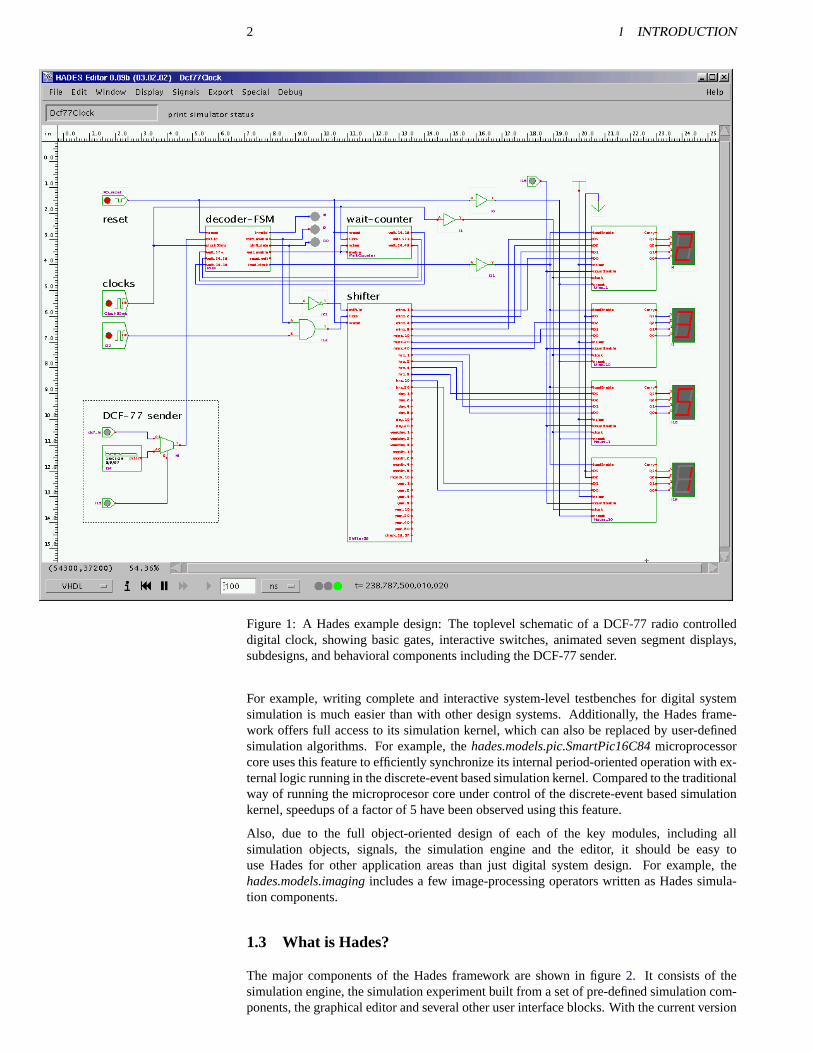
Figure 1: A Hades example design: The toplevel schematic of a DCF-77 radio controlleddigital clock, showing basic gates, interactive switches, animated seven segment displays,subdesigns, and behavioral components including the DCF-77 sender.
For example, writing complete and interactive system-level testbenches for digital systemsimulation is much easier than with other design systems. Additionally, the Hades frame-work offers full access to its simulation kernel, which can also be replaced by user-definedsimulation algorithms. For example, thehades.models.pic.SmartPic16C84microprocessorcore uses this feature to efficiently synchronize its internal period-oriented operation with ex-ternal logic running in the discrete-event based simulation kernel. Compared to the traditionalway of running the microprocesor core under control of the discrete-event based simulationkernel, speedups of a factor of 5 have been observed using this feature.
Also, due to the full object-oriented design of each of the key modules, including allsimulation objects, signals, the simulation engine and the editor, it should be easy touse Hades for other application areas than just digital system design. For example, thehades.models.imagingincludes a few image-processing operators written as Hades simula-tion components.
1.3 What is Hades?
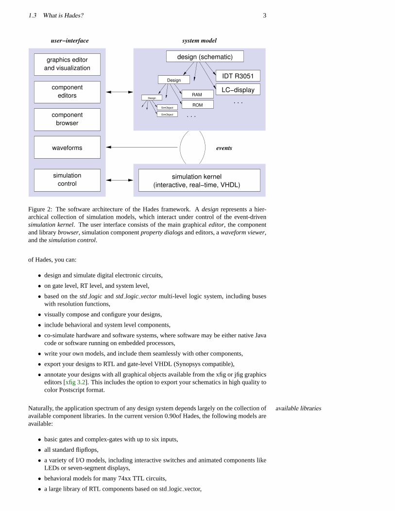
The major components of the Hades framework are shown in figure2. It consists of thesimulation engine, the simulation experiment built from a set of pre-defined simulation com-ponents, the graphical editor and several other user interface blocks. With the current version
1.3 What is Hades? 3
events
simulationcontrol
waveforms
editors
browser
and visualizationgraphics editor
system modeluser−interface
component
component
IDT R3051
ROM
RAM
Design
Design
SimObject
SimObject
. . .
. . .
simulation kernel(interactive, real−time, VHDL)
design (schematic)
LC−display
Figure 2: The software architecture of the Hades framework. Adesignrepresents a hier-archical collection of simulation models, which interact under control of the event-drivensimulation kernel. The user interface consists of the main graphicaleditor, the componentand librarybrowser, simulation componentproperty dialogsand editors, awaveform viewer,and thesimulation control.
of Hades, you can:
• design and simulate digital electronic circuits,
• on gate level, RT level, and system level,
• based on thestd logic andstd logic vectormulti-level logic system, including buseswith resolution functions,
• visually compose and configure your designs,
• include behavioral and system level components,
• co-simulate hardware and software systems, where software may be either native Javacode or software running on embedded processors,
• write your own models, and include them seamlessly with other components,
• export your designs to RTL and gate-level VHDL (Synopsys compatible),
• annotate your designs with all graphical objects available from the xfig or jfig graphicseditors [xfig 3.2]. This includes the option to export your schematics in high quality tocolor Postscript format.
Naturally, the application spectrum of any design system depends largely on the collection ofavailable librariesavailable component libraries. In the current version 0.90of Hades, the following models areavailable:
• basic gates and complex-gates with up to six inputs,
• all standard flipflops,
• a variety of I/O models, including interactive switches and animated components likeLEDs or seven-segment displays,
• behavioral models for many 74xx TTL circuits,
• a large library of RTL components based on stdlogic vector,

4 1 INTRODUCTION
• memories (RAM, ROM, microcode) with graphical memory editors,
• LC-display models, a text terminal (VT52/VT100), UART,
• interfaces to our state-machine editor applet,
• PIC16Cxxx and MIPS R3000 family microcontroller cores,
• LFSR- and BILBO-registers for circuit selftest and signature analysis.
At the moment, all models use a simplified generic timing as might be typical for a 1.0µmCMOS library. If necessary, subclasses with detailed timing data could be generated to modela specific ASIC library accurately. See chapter9 on how to write your own Hades simulationmodels.
1.4 Related Work
Some commercial general-purpose simulation environments are built upon special simula-ModSIM, KHOROStion languages. One example is the SIMGRAPHICS-II environment with its proprietarysimulation language called MODSIM-III [CACI 97]. Most tools, however, use standard pro-gramming languages like Modula, C/C++ or still FORTRAN for their simulation models, andprovide function or class libraries optimized for specific application areas. Perhaps the bestknown example is the KHOROS [Khoral 97] environment for the simulation and visualiza-tion of image processing tasks.
In electronic design automation, interactive schematics and layout editors have been aroundprofessionalEDA tools for years. However, most commercial design systems like Cadence’s Design Framework
[Cadence 97] or Synopsys VSS [Synopsys 97] are targeted towards professional design engi-neers. Therefore, they concentrate on functionality and performance, while ease of use is oflittle concern. Usually, support for interactive (instead of batch mode) simulation is limitedin these frameworks.
On the other hand, several public-domain and shareware tools intended for beginners areDigLOGavailable for the design and simulation of electronic circuits. A well known example are theDigLOG and AnaLOG simulators [Gillespie & Lazzaro 96] from the University of Berkeley.Both simulators use a simple visual editor and provide libraries for all standard componentsand most of the 74xx series. The simulation models are accurate and highly optimized, result-ing in high simulation performance. Behavioural or complex models, however, are difficultto write, because DiGLOG models use a very simple internal language, and support for hi-erarchical designs is limited. Also, the graphical capabilities are limited, because DigLOGuses a proprietary user interface without access to the standard GUI components.
Digsim [DIGSIM] is a digital simulator written injava which supports interactive simulationof simple gate-level circuits. However, support for more complex or hierarchical designs islimited.

5
2 Demos
This chapter presents a few Hades design examples, intended as an overview of the editor andsimulator features. The screenshots used in the following pages were taken on both Windowsand Linux systems, and use several windows managers, to prove the portability of the Hadessoftware.
The first example is a simple gate-level circuit, which illustrates interactive simulation andgate-levelglow-mode. The carry lookahead adder from [Hennessy & Patterson] shows how to use de-sign hierarchy and custom symbols. The next examples demonstrate the interactive state-machine editor and a typical 74xx series circuit.
Three examples are then used to explain the register-transfer level simulation models avail-register-transfer levelable in Hades. A simple 16-bit counter and a user-defined ALU show the individual com-ponents, while the third example presents a complete 16-bit microprocessor with micropro-grammed control, multiport register bank, and external memories.
Next, a MIDI controller based on a PIC16C84 microcontroller demonstrates hardware/soft-cosimulationware-cosimulation. Due to small number of pins on the microcontroller, the keypad anddisplay are multiplexed, which poses interesting problems for visualization.
Finally, an asynchronous micropipeline circuit is presented. The complex handshaking usedscriptingin the micropipeline is an excellent demonstration of the use of interactive simulation. Underthe hood, the simulation models for the C-gates and the registers were written in the Jythonscripting language.
Further design examples are used and explained in the later chapters. Archive files withmost of the examples presented here are available for download at the Hades homepage. Seesection3 for details on downloading.
6 2 DEMOS
2.1 Hamming Code
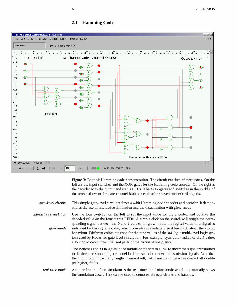
Figure 3: Four-bit Hamming code demonstration. The circuit consists of three parts. On theleft are the input switches and the XOR-gates for the Hamming code encoder. On the right isthe decoder with the output and status LEDs. The XOR-gates and switches in the middle ofthe screen allow to simulate channel faults on each of the seven transmitted signals.
This simple gate-level circuit realizes a 4-bit Hamming-code encoder and decoder. It demon-gate-level circuitsstrates the use of interactive simulation and the visualization with glow-mode.
Use the four switches on the left to set the input value for the encoder, and observe theinteractive simulationdecoded value on the four output LEDs. A simple click on the switch will toggle the corre-sponding signal between the0 and1 values. In glow-mode, the logical value of a signal isindicated by the signal’s color, which provides immediate visual feedback about the circuitglow-modebehaviour. Different colors are used for the nine values of thestd logic multi-level logic sys-tem used by Hades for gate level simulation. For example, cyan color indicates theX value,allowing to detect un-initialized parts of the circuit at one glance.
The switches and XOR-gates in the middle of the screen allow to invert the signal transmittedto the decoder, simulating a channel fault on each of the seven transmission signals. Note thatthe circuit will correct any single channel-fault, but is unable to detect or correct all double(or higher) faults.
Another feature of the simulator is the real-time simulation mode which intentionally slowsreal-time modethe simulation down. This can be used to demonstrate gate-delays and hazards.
2.2 Carry-Lookahead Adder 7
2.2 Carry-Lookahead Adder
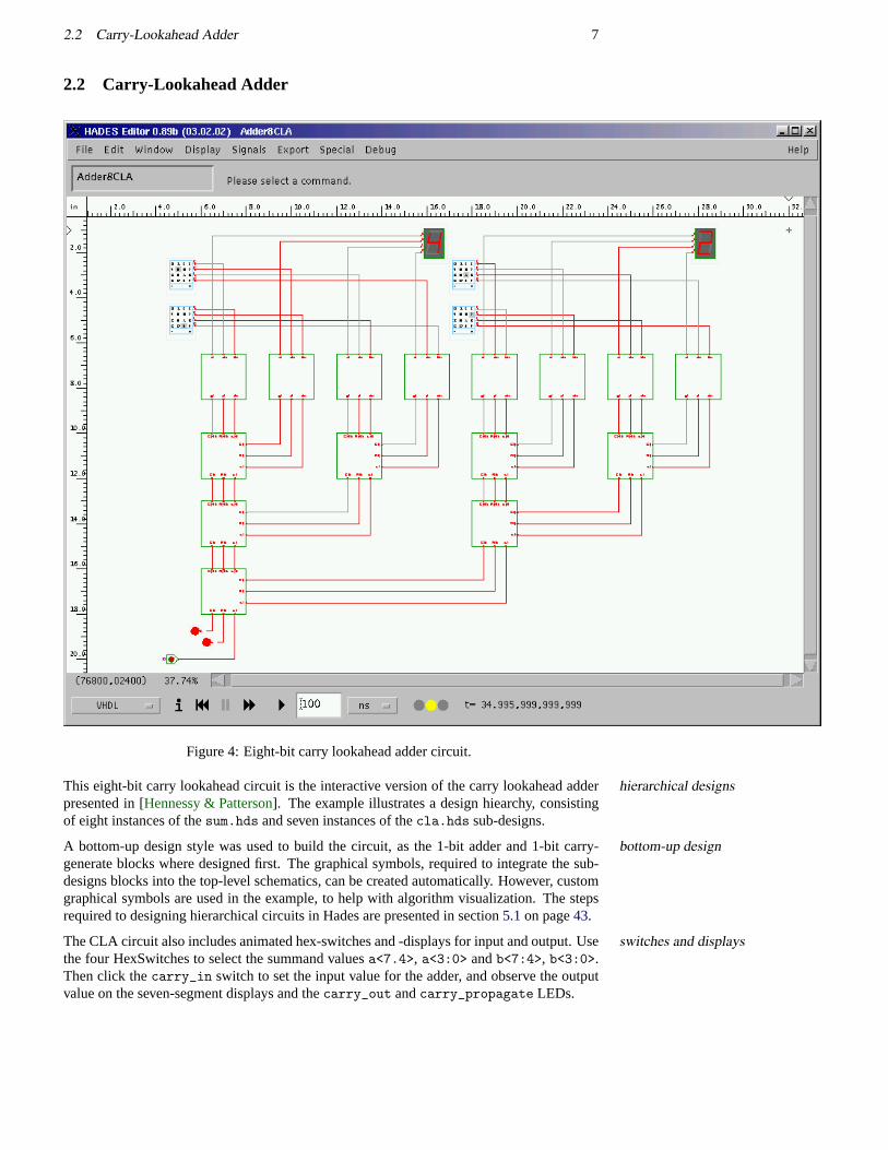
Figure 4: Eight-bit carry lookahead adder circuit.
This eight-bit carry lookahead circuit is the interactive version of the carry lookahead adderhierarchical designspresented in [Hennessy & Patterson]. The example illustrates a design hiearchy, consistingof eight instances of thesum.hds and seven instances of thecla.hds sub-designs.
A bottom-up design style was used to build the circuit, as the 1-bit adder and 1-bit carry-bottom-up designgenerate blocks where designed first. The graphical symbols, required to integrate the sub-designs blocks into the top-level schematics, can be created automatically. However, customgraphical symbols are used in the example, to help with algorithm visualization. The stepsrequired to designing hierarchical circuits in Hades are presented in section5.1on page43.
The CLA circuit also includes animated hex-switches and -displays for input and output. Useswitches and displaysthe four HexSwitches to select the summand valuesa<7.4>, a<3:0> andb<7:4>, b<3:0>.Then click thecarry_in switch to set the input value for the adder, and observe the outputvalue on the seven-segment displays and thecarry_out andcarry_propagate LEDs.
8 2 DEMOS
2.3 Traffic-light controller
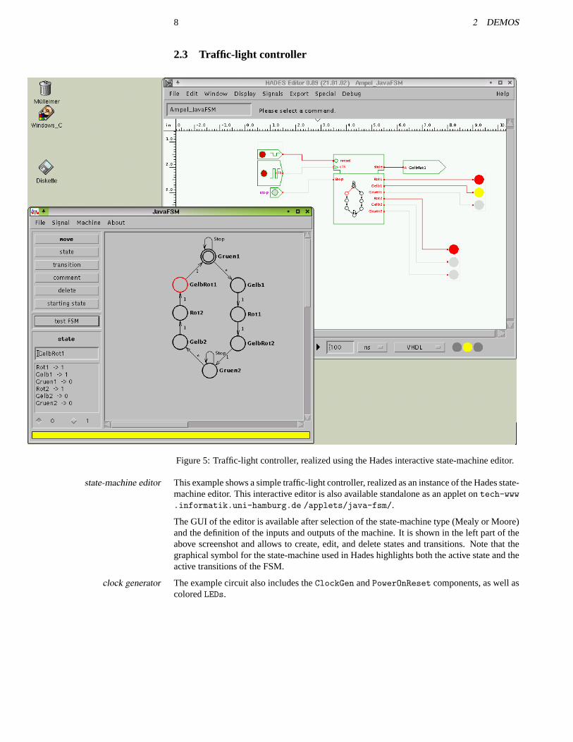
Figure 5: Traffic-light controller, realized using the Hades interactive state-machine editor.
This example shows a simple traffic-light controller, realized as an instance of the Hades state-state-machine editormachine editor. This interactive editor is also available standalone as an applet ontech-www.informatik.uni-hamburg.de /applets/java-fsm/.
The GUI of the editor is available after selection of the state-machine type (Mealy or Moore)and the definition of the inputs and outputs of the machine. It is shown in the left part of theabove screenshot and allows to create, edit, and delete states and transitions. Note that thegraphical symbol for the state-machine used in Hades highlights both the active state and theactive transitions of the FSM.
The example circuit also includes theClockGen andPowerOnReset components, as well asclock generatorcoloredLEDs.
2.4 TTL-series 74xx components 9
2.4 TTL-series 74xx components
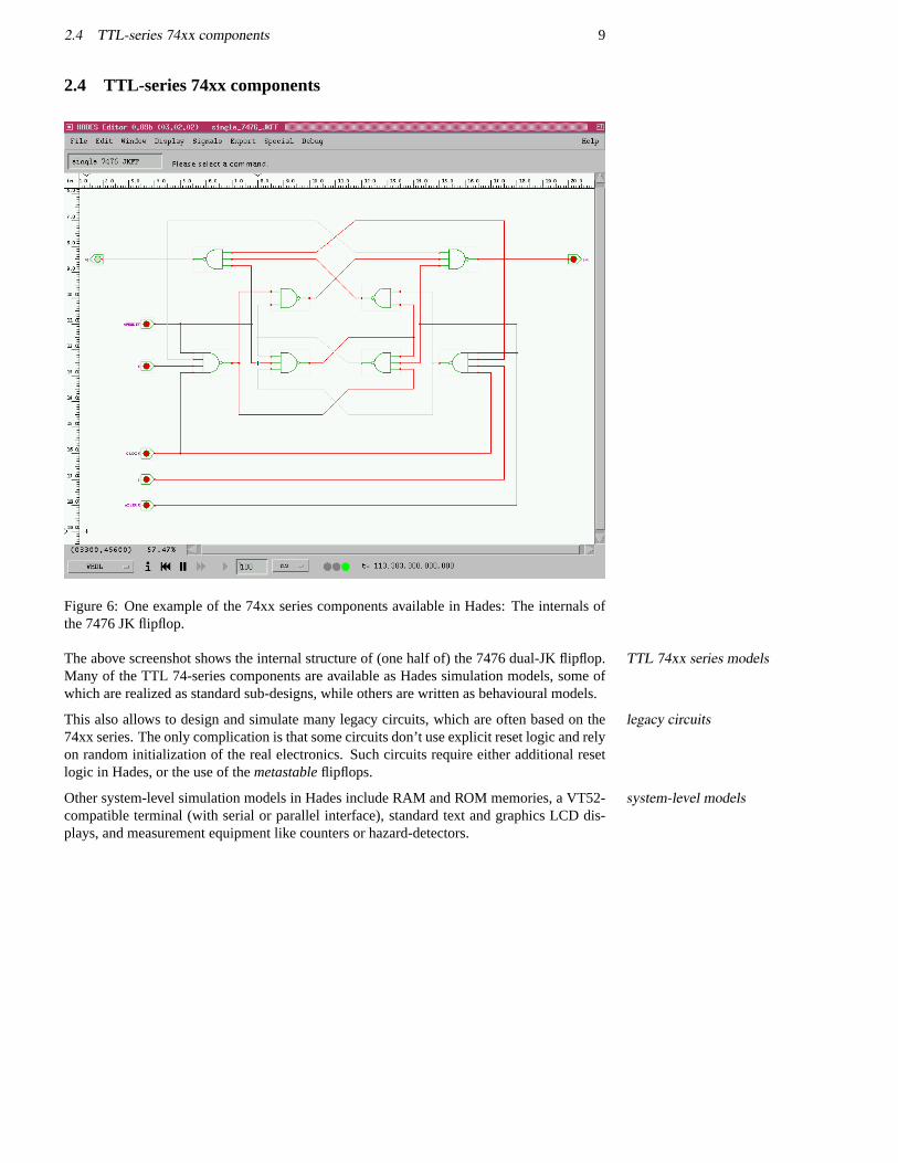
Figure 6: One example of the 74xx series components available in Hades: The internals ofthe 7476 JK flipflop.
The above screenshot shows the internal structure of (one half of) the 7476 dual-JK flipflop.TTL 74xx series modelsMany of the TTL 74-series components are available as Hades simulation models, some ofwhich are realized as standard sub-designs, while others are written as behavioural models.
This also allows to design and simulate many legacy circuits, which are often based on thelegacy circuits74xx series. The only complication is that some circuits don’t use explicit reset logic and relyon random initialization of the real electronics. Such circuits require either additional resetlogic in Hades, or the use of themetastableflipflops.
Other system-level simulation models in Hades include RAM and ROM memories, a VT52-system-level modelscompatible terminal (with serial or parallel interface), standard text and graphics LCD dis-plays, and measurement equipment like counters or hazard-detectors.
10 2 DEMOS
2.5 RTLIB 16-bit counter
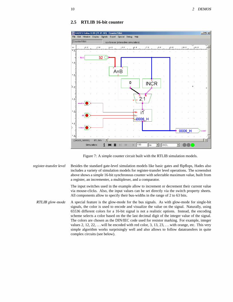
Figure 7: A simple counter circuit built with the RTLIB simulation models.
Besides the standard gate-level simulation models like basic gates and flipflops, Hades alsoregister-transfer levelincludes a variety of simulation models for register-transfer level operations. The screenshotabove shows a simple 16-bit synchronous counter with selectable maximum value, built froma register, an incrementer, a multiplexer, and a comparator.
The input switches used in the example allow to increment or decrement their current valuevia mouse-clicks. Also, the input values can be set directly via the switch property sheets.All components allow to specify their bus-widths in the range of 2 to 63 bits.
A special feature is the glow-mode for the bus signals. As with glow-mode for single-bitRTLIB glow-modesignals, the color is used to encode and visualize the value on the signal. Naturally, using65536 different colors for a 16-bit signal is not a realistic options. Instead, the encodingscheme selects a color based on the the last decimal digit of the integer value of the signal.The colors are chosen as the DIN/IEC code used for resistor marking. For example, integervalues 2, 12, 22, . . . will be encoded with red color, 3, 13, 23, . . . with orange, etc. This verysimple algorithm works surprisingly well and also allows to follow datatransfers in quitecomplex circuits (see below).
2.6 RTLIB user-defined ALU 11
2.6 RTLIB user-defined ALU
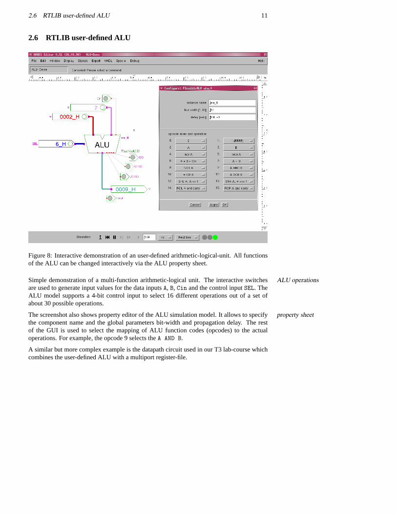
Figure 8: Interactive demonstration of an user-defined arithmetic-logical-unit. All functionsof the ALU can be changed interactively via the ALU property sheet.
Simple demonstration of a multi-function arithmetic-logical unit. The interactive switchesALU operationsare used to generate input values for the data inputsA, B, Cin and the control inputSEL. TheALU model supports a 4-bit control input to select 16 different operations out of a set ofabout 30 possible operations.
The screenshot also shows property editor of the ALU simulation model. It allows to specifyproperty sheetthe component name and the global parameters bit-width and propagation delay. The restof the GUI is used to select the mapping of ALU function codes (opcodes) to the actualoperations. For example, the opcode 9 selects theA AND B.
A similar but more complex example is the datapath circuit used in our T3 lab-course whichcombines the user-defined ALU with a multiport register-file.
12 2 DEMOS
2.7 D*CORE processor
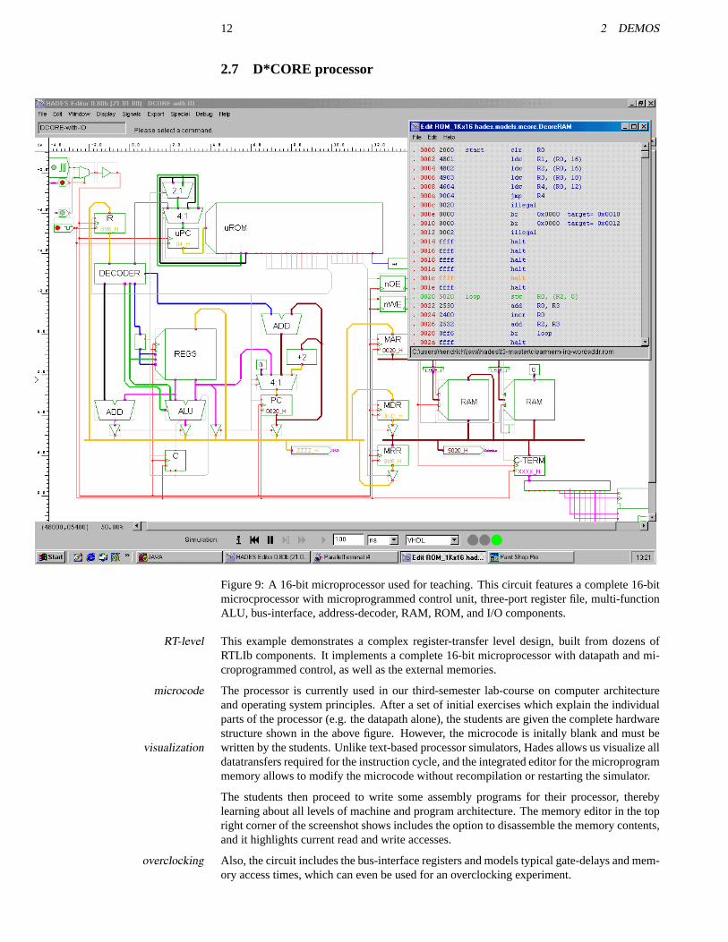
Figure 9: A 16-bit microprocessor used for teaching. This circuit features a complete 16-bitmicrocprocessor with microprogrammed control unit, three-port register file, multi-functionALU, bus-interface, address-decoder, RAM, ROM, and I/O components.
This example demonstrates a complex register-transfer level design, built from dozens ofRT-levelRTLIb components. It implements a complete 16-bit microprocessor with datapath and mi-croprogrammed control, as well as the external memories.
The processor is currently used in our third-semester lab-course on computer architecturemicrocodeand operating system principles. After a set of initial exercises which explain the individualparts of the processor (e.g. the datapath alone), the students are given the complete hardwarestructure shown in the above figure. However, the microcode is initally blank and must bewritten by the students. Unlike text-based processor simulators, Hades allows us visualize allvisualizationdatatransfers required for the instruction cycle, and the integrated editor for the microprogrammemory allows to modify the microcode without recompilation or restarting the simulator.
The students then proceed to write some assembly programs for their processor, therebylearning about all levels of machine and program architecture. The memory editor in the topright corner of the screenshot shows includes the option to disassemble the memory contents,and it highlights current read and write accesses.
Also, the circuit includes the bus-interface registers and models typical gate-delays and mem-overclockingory access times, which can even be used for an overclocking experiment.
2.8 MIDI-controller using a PIC16C84 microcontroller 13
2.8 MIDI-controller using a PIC16C84 microcontroller
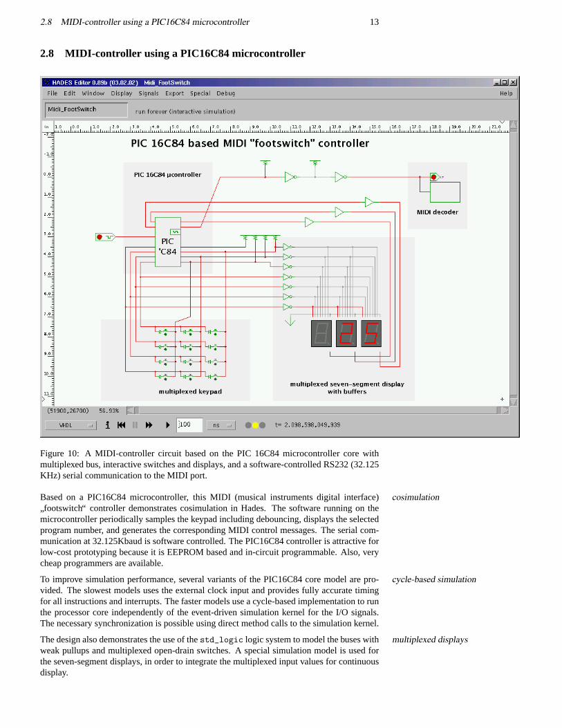
Figure 10: A MIDI-controller circuit based on the PIC 16C84 microcontroller core withmultiplexed bus, interactive switches and displays, and a software-controlled RS232 (32.125KHz) serial communication to the MIDI port.
Based on a PIC16C84 microcontroller, this MIDI (musical instruments digital interface)cosimulation
”footswitch“ controller demonstrates cosimulation in Hades. The software running on the
microcontroller periodically samples the keypad including debouncing, displays the selectedprogram number, and generates the corresponding MIDI control messages. The serial com-munication at 32.125Kbaud is software controlled. The PIC16C84 controller is attractive forlow-cost prototyping because it is EEPROM based and in-circuit programmable. Also, verycheap programmers are available.
To improve simulation performance, several variants of the PIC16C84 core model are pro-cycle-based simulationvided. The slowest models uses the external clock input and provides fully accurate timingfor all instructions and interrupts. The faster models use a cycle-based implementation to runthe processor core independently of the event-driven simulation kernel for the I/O signals.The necessary synchronization is possible using direct method calls to the simulation kernel.
The design also demonstrates the use of thestd_logic logic system to model the buses withmultiplexed displaysweak pullups and multiplexed open-drain switches. A special simulation model is used forthe seven-segment displays, in order to integrate the multiplexed input values for continuousdisplay.
14 2 DEMOS
2.9 Micropipeline
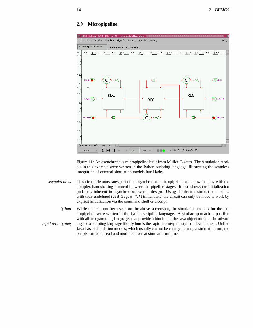
Figure 11: An asynchronous micropipeline built from Muller C-gates. The simulation mod-els in this example were written in the Jython scripting language, illustrating the seamlessintegration of external simulation models into Hades.
This circuit demonstrates part of an asynchronous micropipeline and allows to play with theasynchronouscomplex handshaking protocol between the pipeline stages. It also shows the initializationproblems inherent in asynchronous system design. Using the default simulation models,with their undefined (std_logic ’U’) initial state, the circuit can only be made to work byexplicit initialization via the command shell or a script.
While this can not been seen on the above screenshot, the simulation models for the mi-Jythoncropipeline were written in the Jython scripting language. A similar approach is possiblewith all programming languages that provide a binding to the Java object model. The advan-tage of a scripting language like Jython is the rapid prototyping style of development. Unlikerapid prototypingJava-based simulation models, which usually cannot be changed during a simulation run, thescripts can be re-read and modified even at simulator runtime.
15
3 Installation
This section presents all steps required to get the Hades editor and simulator to work. Itinstallation overviewfirst discusses the system requirements and the selection of a suitable Java virtual machine.Sections3.3and3.4describe the software download and the setup of a working directory foryour designs. Two examples show how to register the Hades.hds files as a new file typeon Windows systems. Finally, section3.11and3.10describe multi-user setup and the stpsJython insta
To get Hades running on your system, follow these steps:
1. check that your computer meets the system requirements.
2. verify that you have a suitable Java virtual machine, e.g. a version of JDK 1.3 or theMicrosoft VM.
3. visit the Hades homepage and download the software, documentation, and examples.
4. create a suitable working directory for the design examples and your own designs.
5. create script files to start the Hades editor with the correct options. You may also wantto register.hds design files with your operating system.
6. use the software. See the next chapter4 for a walk-through on a simple design example.
7. if you experience problems, see the FAQ (section10) for help.
The Hades editor can also be used as an applet in any fully Java 1.1 compatible web browser.applet compatibilityDue to the size of the Hades software, however, this works well in a high-bandwidth intranet,but is less suited to repeated modem download. Therefore, it might be nesessary to install thesimulator locally, even when using it as an applet. The details of applet installation are arediscussed in section3.12.
3.1 System requirements
Hades is written as a pure Java 1.1 program [Sun 97]. Therefore, Hades should run with- pure Javaout modification on every computer system that offers a Java 1.1 compatible Java virtualmachine (JVM). This includes PCs or workstations running either Windows 95/98/ME, Win-dows NT/2000/XP, or Linux, most commercial versions of Unix like Solaris or AIX, and theApple MacOS. In principle, Hades should also work on systems like fast PDAs and organizersif a JVM is available for that system.
Because of its user interface, which is centered around a graphical editor, a large and high-screen sizeresolution monitor is recommmended for running Hades. A display of 1024x768 pixelsshould be ok, but the higher the better. Depending on your font setup, some dialog win-dows may not fit on the screen at resolutions of 800x600 or lower. However, the simulatorcan also be run as a standalone application in text-mode without user interface if necessary.
For acceptable performance, a fast processor (Pentium, Athlon, PowerPC, UltraSPARC) andevents/second64 MBytes of main memory are recommended. A Pentium-II 300 system with 64 MBytesis more than adequate to run most of our educational designs. However, the simulation oflarger circuits with ten-thousands of gates may require 256MB of memory (or more). On amodern Pentium-IV or Athlon based PC with a current JVM, Hades performance can surpassone million simulated events per second. While Hades should also run on older hardware likea 486 or microSPARC processor, you probably won’t like the performance.
When running a simulation, Hades stresses many parts of the JVM and operating system,OS versionsespecially the graphics system due to frequent full-screen repaints, but also thread synchro-nization and memory management including garbage-collection. Problems resulting frombugs in old versions of the operating systems libraries can often be solved by upgrading.Note that no stable Java virtual machines are available for Windows 3.11 and older versionof Linux (e.g. kernels 2.0.x).
16 3 INSTALLATION
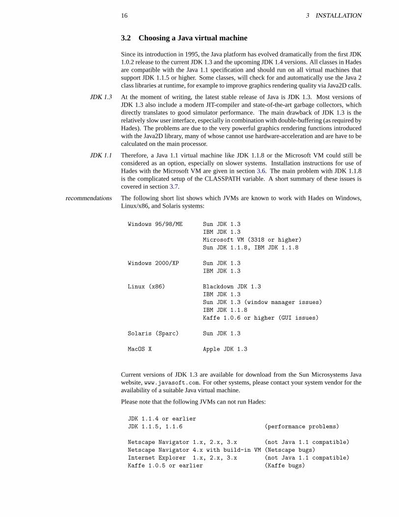
3.2 Choosing a Java virtual machine
Since its introduction in 1995, the Java platform has evolved dramatically from the first JDK1.0.2 release to the current JDK 1.3 and the upcoming JDK 1.4 versions. All classes in Hadesare compatible with the Java 1.1 specification and should run on all virtual machines thatsupport JDK 1.1.5 or higher. Some classes, will check for and automatically use the Java 2class libraries at runtime, for example to improve graphics rendering quality via Java2D calls.
At the moment of writing, the latest stable release of Java is JDK 1.3. Most versions ofJDK 1.3JDK 1.3 also include a modern JIT-compiler and state-of-the-art garbage collectors, whichdirectly translates to good simulator performance. The main drawback of JDK 1.3 is therelatively slow user interface, especially in combination with double-buffering (as required byHades). The problems are due to the very powerful graphics rendering functions introducedwith the Java2D library, many of whose cannot use hardware-acceleration and are have to becalculated on the main processor.
Therefore, a Java 1.1 virtual machine like JDK 1.1.8 or the Microsoft VM could still beJDK 1.1considered as an option, especially on slower systems. Installation instructions for use ofHades with the Microsoft VM are given in section3.6. The main problem with JDK 1.1.8is the complicated setup of the CLASSPATH variable. A short summary of these issues iscovered in section3.7.
The following short list shows which JVMs are known to work with Hades on Windows,recommendationsLinux/x86, and Solaris systems:
Windows 95/98/ME Sun JDK 1.3IBM JDK 1.3Microsoft VM (3318 or higher)Sun JDK 1.1.8, IBM JDK 1.1.8
Windows 2000/XP Sun JDK 1.3IBM JDK 1.3
Linux (x86) Blackdown JDK 1.3IBM JDK 1.3Sun JDK 1.3 (window manager issues)IBM JDK 1.1.8Kaffe 1.0.6 or higher (GUI issues)
Solaris (Sparc) Sun JDK 1.3
MacOS X Apple JDK 1.3
Current versions of JDK 1.3 are available for download from the Sun Microsystems Javawebsite,www.javasoft.com. For other systems, please contact your system vendor for theavailability of a suitable Java virtual machine.
Please note that the following JVMs can not run Hades:
JDK 1.1.4 or earlierJDK 1.1.5, 1.1.6 (performance problems)
Netscape Navigator 1.x, 2.x, 3.x (not Java 1.1 compatible)Netscape Navigator 4.x with build-in VM (Netscape bugs)Internet Explorer 1.x, 2.x, 3.x (not Java 1.1 compatible)Kaffe 1.0.5 or earlier (Kaffe bugs)
3.3 Hades Download 17
3.3 Hades Download
Unless you receive the Hades software on CDROM or magnetic media, please visit the HadesHades homepagehomepage,tech-www.informatik.uni-hamburg.de/applets/hades for information,design examples, and software download. Also, the website includes a few applet demosof Hades, which allows to test-drive the simulator directly in your browser.
First, use your favorite WWW-browser to download the software, which is packed into anhades.jarexecutable JAR/Zip-format archive file. Following the usual naming conventions, the fileshould be calledhades.jar, and that file is indeed available on our server. However, pleasedon’t download thehades.jar file directly, unless you are 100% sure that your browserunderstands about.jar files. Unfortunately, many Windows browsers are misconfiguredand seem to download.jar-files in text-mode, which destroys the archive contents. Thisproblem was reported against both Netscape and Internet Explorer.
Therefore, the recommended way to download the software is to download thehades.zip hades.zipfile instead. This is exactly the same file ashades.jar, but most browsers understand the.zip filename extension and use the necessary binary-mode for data transfer. After the down-load is finished, rename thehades.zip file to the correcthades.jar name.
(On Windows systems, ignore the explorer warning message that changing the filename may Windows troublesbe harmful, as restoring the correct file type association is the whole point of the renaming.If the Windows explorer does not print a warning message, you should carefully check theresulting file name. If thehide extensions for known file typessetting is active, renaming thehades.zip file to hades.jar in Explorer may result in something likehades.jar.zip. Ifyou suspect such a problem, use a command shell to rename the file).
After downloading,do not unpackthe archive file. Most current Java virtual machines workdo not unpack!much faster when accessing classes and resources from the packed archive file, instead ofloading hundreds of individual files. Also, the signatures and main-class attributes in thearchive will not work after unpacking.
However, if you suspect that thehades.jar file was damaged during download, you can useyour favorite packer tool to list the archive contents. For example, try to open the archive inWinZip, PowerArchiver, or use thejar-utility program from the JDK,jar tf hades.jar.This should print or list several hundred files.
The download area on the Hades homepage also offers some documentation and design ex-docs and examplesamples. All recent documentation files use the PDF document format, while older files areavailable in (compressed) Postscript format. The design examples archive files are in ZIP-format and should be downloadable with all current browsers.
3.4 Making a directory
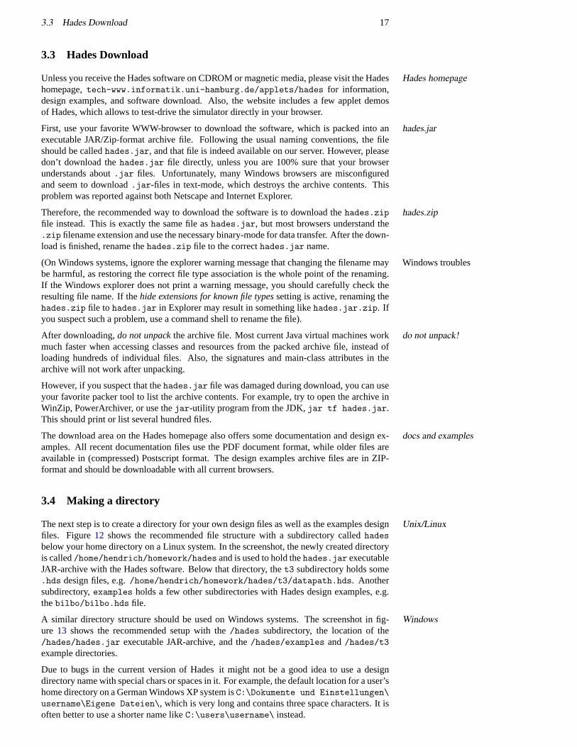
The next step is to create a directory for your own design files as well as the examples designUnix/Linuxfiles. Figure12 shows the recommended file structure with a subdirectory calledhadesbelow your home directory on a Linux system. In the screenshot, the newly created directoryis called/home/hendrich/homework/hades and is used to hold thehades.jar executableJAR-archive with the Hades software. Below that directory, thet3 subdirectory holds some.hds design files, e.g./home/hendrich/homework/hades/t3/datapath.hds. Anothersubdirectory,examples holds a few other subdirectories with Hades design examples, e.g.thebilbo/bilbo.hds file.
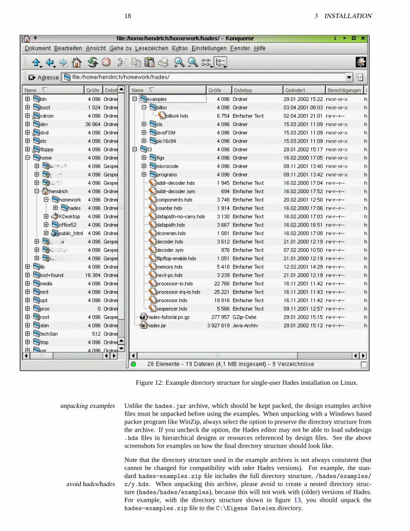
A similar directory structure should be used on Windows systems. The screenshot in fig-Windowsure 13 shows the recommended setup with the/hades subdirectory, the location of the/hades/hades.jar executable JAR-archive, and the/hades/examples and/hades/t3example directories.
Due to bugs in the current version of Hades it might not be a good idea to use a designdirectory name with special chars or spaces in it. For example, the default location for a user’shome directory on a German Windows XP system isC:\Dokumente und Einstellungen\username\Eigene Dateien\, which is very long and contains three space characters. It isoften better to use a shorter name likeC:\users\username\ instead.
18 3 INSTALLATION
Figure 12: Example directory structure for single-user Hades installation on Linux.
Unlike thehades.jar archive, which should be kept packed, the design examples archiveunpacking examplesfiles must be unpacked before using the examples. When unpacking with a Windows basedpacker program like WinZip, always select the option to preserve the directory structure fromthe archive. If you uncheck the option, the Hades editor may not be able to load subdesign.hds files in hierarchical designs or resources referenced by design files. See the abovescreenshots for examples on how the final directory structure should look like.
Note that the directory structure used in the example archives is not always consistent (butcannot be changed for compatibility with oder Hades versions). For example, the stan-dardhades-examples.zip file includes the full directory structure,/hades/examples/x/y.hds. When unpacking this archive, please avoid to create a nested directory struc-avoid hades/hadesture (hades/hades/examples), because this will not work with (older) versions of Hades.For example, with the directory structure shown in figure13, you should unpack thehades-examples.zip file to theC:\Eigene Dateien directory.
3.5 Installation with JDK 1.3 19
Figure 13: Example directory structure for single-user Hades installation on Windows.
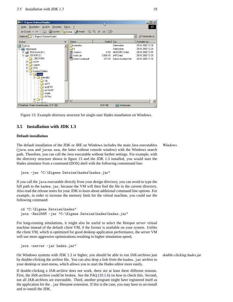
3.5 Installation with JDK 1.3
Default installation
The default installation of the JDK or JRE on Windows includes the main Java executablesWindows(java.exe andjavaw.exe, the latter without console window) with the Windows searchpath. Therefore, you can call the Java executable without further settings. For example, withthe directory structure shown in figure13 and the JDK 1.3 installed, you would start theHades simulator from a command (DOS) shell with the following commmand line:
java -jar "C:\Eigene Dateien\hades\hades.jar"
If you call thejava executable directly from your design directory, you can avoid to type thefull path to thehades.jar, because the VM will then find the file in the current directory.Also read the release notes for your JDK to learn about additional command line options. Forexample, in order to increase the memory limit for the virtual machine, you could use thefollowing command:
cd "C:\Eigene Dateien\hades"java -Xmx256M -jar "C:\Eigene Dateien\hades\hades.jar"
For long-running simulations, it might also be useful to select the Hotspotservervirtualmachine instead of the defaultclient VM, if the former is available on your system. Unlikethe client VM, which is optimized for good desktop application performance, the server VMwill use more aggressive optimizations resulting in higher simulation speed,
java -server -jar hades.jar"
On Windows systems with JDK 1.3 or higher, you should be able to run JAR-archives justdouble-clicking hades.jarby double-clicking the archive file. You can also drop a link from thehades.jar archive toyour desktop or start-menu, which allows you to start the Hades editor more easily.
If double-clicking a JAR-archive does not work, there are at least three different reasons.First, the JAR-archive could be broken. See the FAQ (10.1.6) on how to check this. Second,not all JAR-archives are executable. Third, another program might have registered itself asthe application for the.jar filename extension. If this is the case, you may have to un-installand re-install the JDK.
20 3 INSTALLATION
The situation on Linux and Unix platforms is a little bit more complicated, due to differencesUnix and Linuxbetween the vendor’s virtual machines and the directory structure used by your operating sys-tem. For example, the JDK 1.3 could be installed in/opt/jdk1.3, /opt/sfw/j2sdk1.3.1,/usr/lib/jdk1.3, etc.
If multiple versions of the JDK are installed, the JDK 1.3java executable will probably notbe included with the default user search path. In that case, simply use the absolute path toreference and call the JVM. For example,
cd /home/hendrich/homework/hades/usr/lib/jdk1.3.1/bin/java -jar hades.jar
Using the JDK extension package mechanism
Instead of manually setting the CLASSPATH environment variable, all versions of the JDKJava 2: extension packagessince 1.2.2 also support theJava 2 extension mechanism. Basically, the trick is that the JDKalso searches a special directory for.jar archives when looking for Java classes. Therefore,it is not necessary to use CLASSPATH for all JAR archives copied to that directory.
On current Windows and Unix versions of the JDK or JRE, this magic directory is calledJDKDIR/jre/lib/ext<JDKDIR>/jre/lib/ext and is initially empty after a default JDK or JRE installation(where<JDKDIR> means the base directory of the JDK installation, e.g.C:\jdk1.3.1 or/opt/j2sdk1.3.1). Just copy thehades.jar file into this directory and change the filepermission flags to allow read access for all users, if necessary. Note that theext directorymay only be writable for the system administrator on Unix or Linux systems. If you want touse Jython for scripting you may also want to copy thejython.jar to the ext directory, seesection3.10.
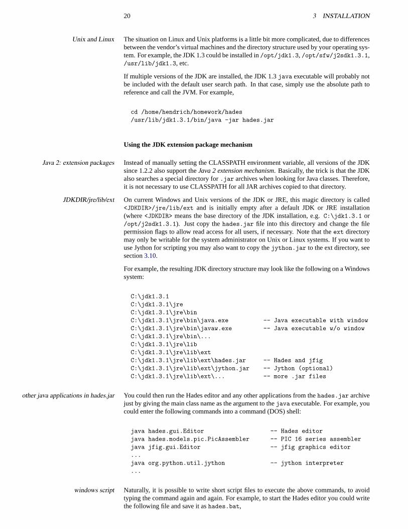
For example, the resulting JDK directory structure may look like the following on a Windowssystem:
C:\jdk1.3.1C:\jdk1.3.1\jreC:\jdk1.3.1\jre\binC:\jdk1.3.1\jre\bin\java.exe -- Java executable with windowC:\jdk1.3.1\jre\bin\javaw.exe -- Java executable w/o windowC:\jdk1.3.1\jre\bin\...C:\jdk1.3.1\jre\libC:\jdk1.3.1\jre\lib\extC:\jdk1.3.1\jre\lib\ext\hades.jar -- Hades and jfigC:\jdk1.3.1\jre\lib\ext\jython.jar -- Jython (optional)C:\jdk1.3.1\jre\lib\ext\... -- more .jar files
You could then run the Hades editor and any other applications from thehades.jar archiveother java applications in hades.jarjust by giving the main class name as the argument to thejava executable. For example, youcould enter the following commands into a command (DOS) shell:
java hades.gui.Editor -- Hades editorjava hades.models.pic.PicAssembler -- PIC 16 series assemblerjava jfig.gui.Editor -- jfig graphics editor...java org.python.util.jython -- jython interpreter...
Naturally, it is possible to write short script files to execute the above commands, to avoidwindows scripttyping the command again and again. For example, to start the Hades editor you could writethe following file and save it ashades.bat,
3.6 Installation with the Microsoft VM (jview) 21
rem file hades.batrem run the Hades editor with JDK (1.3), no CLASSPATH required,rem because hades.jar is in JDKDIR/jre/lib/ext/hades.jar,rem allow up to 256 MByte of memoryremjavaw -Xmx256M hades.gui.Editor
Here is a similar script for Unix. Set the execute permission (x) bits for the script file andUnixcopy it to one of the directories in your search path:
# hades.binjava -Xmx256M hades.gui.Editor -file $1
The obvious advantage of using the extension mechanism is that all classes in the exten-pro and contrasion packages are instantly useable by all Java applications, without any further complicatedCLASSPATH setup. The disadvantage is the possible conflict between classes installed lo-cally and the classes in the extension directory. Therefore, the extension mechanism shouldonly be used for stable packages, but not during development.
3.6 Installation with the Microsoft VM (jview)
Due to its excellent integration into the Windows system, the Microsoft Java virtual machineMicrosoft VMis still a good choice to run Hades on Windows 95/98/ME and Windows NT/2000 systems.Because the virtual machine is installed as part of the Internet Explorer setup, it is availableon many Windows systems. While the Microsoft VM only uses the JDK 1.1.4 Java specifi-cation, its JIT-compiler and garbage-collector are quite fast, and it offers excellent GUI per-formance, resulting in very fast repaints and animations when running Hades in glow-mode.Unfortunately, Microsoft has decided not to include its VM with Windows XP.
Please check that you are using version 3.318 or newer, because older versions will notversion issues and downloadwork with Hades. Just open a command shell and typejview. If the Microsoft VM isinstalled, this command will print a short help message which includes the version infor-mation. The Microsoft JVM install package is available via the Microsoft web site fromwww.microsoft.com/java/.
The command syntax forjview is similar to JDK but differs in the details. Most importantly,jview command syntaxthe Microsoft VM expects the/cp or/cp:a options to specify the directories or JAR-archiveswhich are searched for Java class files. The/cp:a means to append the specifed directory tothe jview classpath. For example, with the directory structure shown in figure13, you woulduse the following commands:
rem hades.batrem run the Hades editor with the Microsoft VMrem (version 3318 or greater recommended)remjview /cp:a "C:\Eigene Dateien\hades\hades.jar" hades.gui.Editor
Just substitute the path to yourhades.jar archive.
3.7 Installation with other JVMs
JDK 1.1.8 This is the last release version in the JDK 1.1 family of virtual machines. EvenJDK 1.1.8those Java applications which do not require the newer features of the Java 2 platform speci-fication, will usually run better with a recent version of the JDK 1.3.
There is, however, one exception, namely applications which rely on fast interactive full-screen graphics. Due to the less complex graphics in Java 1.1, double-buffered graphics isusually much faster with JDK 1.1.8 virtual machines than with JDK 1.2.x or even the latest
22 3 INSTALLATION
JDK 1.3.x versions, which directly translates to Hades redraw performance. Therefore, evenif the raw simulator performance of Hades may be much lower on JDK 1.1.8, the editor maystill seem faster. This effect becomes more noticable on slow graphics cards; for example,the JDK 1.3 rendering performance on older UltraSPARC workstations with TGX (8-bit)graphics adapters is dismal.
The main problem with using JDK 1.1.8 is the complex setup, which requires setting theCLASSPATH variable and differs for the JDK and JRE, the several JDK/JRE vendors, andthe use of the CLASSPATH environment variable or the-classpath command line option.The general principle is to include all application JAR-archives as well as the JDK runtimeJAR-archive in the CLASSPATH. For example,
# JDK 1.1.8 Unix/Linux with csh/tcshsetenv CLASSPATH /opt/jdk1.1.8/lib/classes.zipsetenv CLASSPATH ${CLASSPATH}:/home/hendrich/homework/hades.jar/opt/jdk1.1.8/bin/java -mx128M hades.gui.Editor
KAFFE This is a complete open-source Java 1.1 compatible virtual machine with inter-Kaffe VMpreter, JIT-compiler, and a full implementation of the standard Java libraries including AWTand RMI. See the project homepage atwww.kaffe.org for details.
Recent versions ofkaffe (1.0.6 or higher) should be able to run Hades. See thekaffedocumentation on your system for details on how to include thehades.jar into thekaffeCLASSPATH and how to run thekaffe tools. The simulator works well, at least for thesmaller design examples. However, you may experience user interface delays during garbagecollection and the redraw performance could be better. Also, some of the user interface codein Hades seems to expose bugs in thekaffe AWT implementation.
GCJ The Gnu compiler for Javaproject aims to create both a Java frontend for thegccnative compilationcompiler and an implementation of the standard Java libraries. See the project homepageat gcc.gnu.org/java/ for details. Thegcj tools allow to compile Java application tonative binaries with all usual compiler optimiziations, instead of relying on a virtual machineand a JIT compiler. While it is not clear whether static compilation really provides betterperformance, especially for long-running applications like Hades, it does reduce applicationstartup times and allows a lot of fine-tuning.
At the time of writing, thegcj compiler itself is working quite well and can compile all Hadesbut no AWT yetsource code. Unfortunately, the AWT window toolkit classes in thelibgcj support librariesare still incomplete and cannot be used to run Hades. Once thelibgcj project includes aworking AWT, it will be interesting to see how well a native-compiled Hades binary performs.
3.8 User preferences and configuration
At application startup, the Hades editor first reads a global configuration file included in theeditor startuphades.jar archive, and then searches for user-defined configuration files. This allows tochange the default configuration and editor behaviour to your preferences. Currently, theeditor uses the following sequence to read the configuration data. It first reads the defaultconfiguration from the file/hades/.hadesrc contained in thehades.jar archive. If abso-lutely necessary, you could use thejar tool from JDK 1.3 with the update option to changethe global configuration file inside thehades.jar. Next, the editor tries to read a file called.hadesrc in your home directory. Finally, it tries to read a.hadesrc file in the currentworking directory. This hierarchy means that you can have global (default) attributes, youruser preferences, and also local preferences for each Hades design or project.
For example, you can decide whether the simulator should start automatically after a designfile has been loaded, you can specify the initial window size and position, colors to be usedfor glow-mode, etc. See appendixA on page110 for the list of the available property keysand their default values.
3.9 Registering .hds files on Windows 23
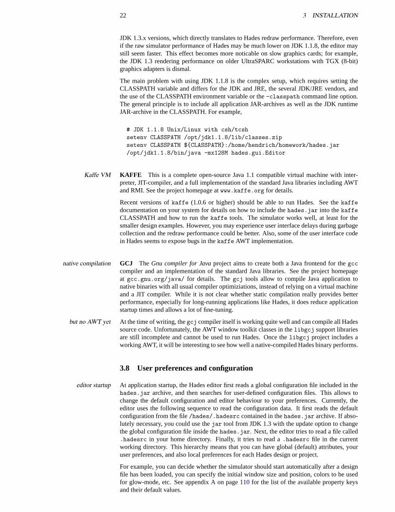
Figure 14: Screenshot of the Hades properties viewer, showing a few of the properties whichcontrol the editor and simulator startup behaviour.
To edit the configuration files, start the Hades editor and then selectMenu. Special. Showproperties. . . to open the properties viewer. The screenshot in figure14 shows the Hadesproperties viewer window, together with some property keys and values. The bottom partof the properties viewer window shows the filenames for your user- and local- (workingdirectory) properties files. Clicking on one of the buttons will export all properties fromthe dialog window to the corresponding file. Note that the propertiews viewer only exportsproperty keys whose values start with"hades" or "jfig". Naturally, you can also write andedit the.hadesrc startup files directly with your favorite editor.
3.9 Registering .hds files on Windows
If you prefer a document-oriented style of working, you may want to register a new file typefor Hades design files and to associate that file type with your JVM and the Hades editor.Upon double-clicking a.hds design file, your operating system would then start the Javavirtual machine, initialize the Hades editor and then load the design file into the editor.
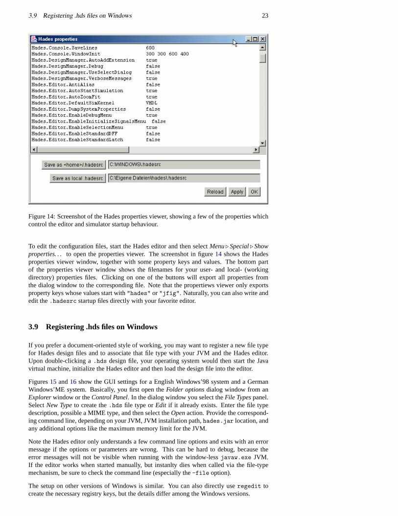
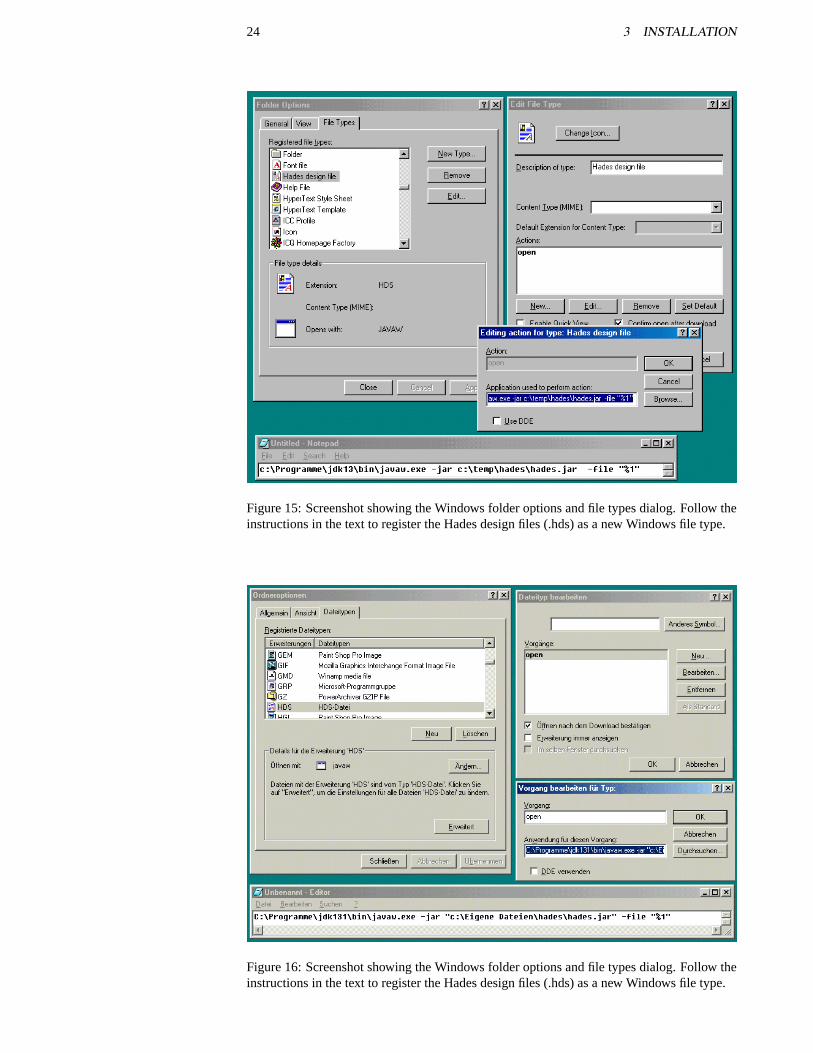
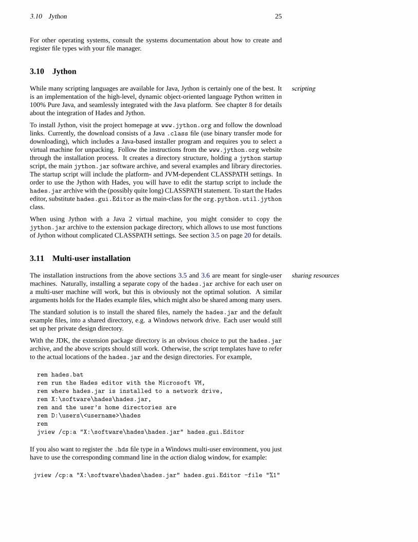
Figures15 and16 show the GUI settings for a English Windows’98 system and a GermanWindows’ME system. Basically, you first open theFolder optionsdialog window from anExplorerwindow or theControl Panel. In the dialog window you select theFile Typespanel.SelectNew Typeto create the.hds file type orEdit if it already exists. Enter the file typedescription, possible a MIME type, and then select theOpenaction. Provide the correspond-ing command line, depending on your JVM, JVM installation path,hades.jar location, andany additional options like the maximum memory limit for the JVM.
Note the Hades editor only understands a few command line options and exits with an errormessage if the options or parameters are wrong. This can be hard to debug, because theerror messages will not be visible when running with the window-lessjavaw.exe JVM.If the editor works when started manually, but instanlty dies when called via the file-typemechanism, be sure to check the command line (especially the-file option).
The setup on other versions of Windows is similar. You can also directly useregedit tocreate the necessary registry keys, but the details differ among the Windows versions.
24 3 INSTALLATION
Figure 15: Screenshot showing the Windows folder options and file types dialog. Follow theinstructions in the text to register the Hades design files (.hds) as a new Windows file type.
Figure 16: Screenshot showing the Windows folder options and file types dialog. Follow theinstructions in the text to register the Hades design files (.hds) as a new Windows file type.
3.10 Jython 25
For other operating systems, consult the systems documentation about how to create andregister file types with your file manager.
3.10 Jython
While many scripting languages are available for Java, Jython is certainly one of the best. Itscriptingis an implementation of the high-level, dynamic object-oriented language Python written in100% Pure Java, and seamlessly integrated with the Java platform. See chapter8 for detailsabout the integration of Hades and Jython.
To install Jython, visit the project homepage atwww.jython.org and follow the downloadlinks. Currently, the download consists of a Java.class file (use binary transfer mode fordownloading), which includes a Java-based installer program and requires you to select avirtual machine for unpacking. Follow the instructions from thewww.jython.org websitethrough the installation process. It creates a directory structure, holding ajython startupscript, the mainjython.jar software archive, and several examples and library directories.The startup script will include the platform- and JVM-dependent CLASSPATH settings. Inorder to use the Jython with Hades, you will have to edit the startup script to include thehades.jar archive with the (possibly quite long) CLASSPATH statement. To start the Hadeseditor, substitutehades.gui.Editor as the main-class for theorg.python.util.jythonclass.
When using Jython with a Java 2 virtual machine, you might consider to copy thejython.jar archive to the extension package directory, which allows to use most functionsof Jython without complicated CLASSPATH settings. See section3.5on page20 for details.
3.11 Multi-user installation
The installation instructions from the above sections3.5 and3.6 are meant for single-user sharing resourcesmachines. Naturally, installing a separate copy of thehades.jar archive for each user ona multi-user machine will work, but this is obviously not the optimal solution. A similararguments holds for the Hades example files, which might also be shared among many users.
The standard solution is to install the shared files, namely thehades.jar and the defaultexample files, into a shared directory, e.g. a Windows network drive. Each user would stillset up her private design directory.
With the JDK, the extension package directory is an obvious choice to put thehades.jararchive, and the above scripts should still work. Otherwise, the script templates have to referto the actual locations of thehades.jar and the design directories. For example,
rem hades.batrem run the Hades editor with the Microsoft VM,rem where hades.jar is installed to a network drive,rem X:\software\hades\hades.jar,rem and the user’s home directories arerem D:\users\<username>\hadesremjview /cp:a "X:\software\hades\hades.jar" hades.gui.Editor
If you also want to register the.hds file type in a Windows multi-user environment, you justhave to use the corresponding command line in theactiondialog window, for example:
jview /cp:a "X:\software\hades\hades.jar" hades.gui.Editor -file "%1"
26 3 INSTALLATION
3.12 Applet installation and issues
The Hades editor will also run as an applet in a fully Java 1.1 compatible browser. Unfortu-browsersnately, the default Java virtual machines in all versions of Netscape 2.x, 3.x, 4.x are brokenand will not work. On the other hand, the Microsoft VM in Internet Explorer works, butgetting the security settings right is version dependent. Therefore, you should use the JDK1.3 Java pluginas the JVM for running the Hades applet. This includes Mozilla, Netscape6, Netscape 4.78+ with the Java plugin, Internet Explorer with the Java plugin, and possiblyother browsers like Opera or Konqueror. See your browser documentation for details.
Note that the fullhades.zip archive file is currently over 3 MBytes in size. As the appletdownload timescode is downloaded each time the applet is started, this will only work in a fast intranet butnot via a modem connection. However, it is possible to create a much smaller archive file, ifyou do not need all simulation models or GUI components. The administrator for the appletwebserver will probably employ an optimized version.
Also, the applet server might use the new Java WebStart protocol, which supports a one-Java WebStarttime download the applet software, but checks for applet updates. If you plan to use theHades applet via a slow modem connection, you should install the WebStart support on yourcomputer.
The default security settings for JDK 1.3 applets restrict all access to files on your machine.security and file accessTherefore, the Hades editor applet cannot save your designs or resources to your system. Ifyou want to enable file access, you will have to change the.java.policy Java Policy filein your home directory. The JDK includes an extra program,policytool to edit the policyfile. If you don’t like the GUI of policytool, you can also edit the policy file directly withyour favorite text editor. However, the JVM SecurityManager is sensitive to syntax errors inthe policy file and will (silently) deny access to resources.
The following example shows how to allow full read, write, delete, and execute access to allpolicy filefiles on your local machine. Naturally, these settings are not recommended due to the securityproblems:
/* AUTOMATICALLY GENERATED ON Thu Oct 04 11:12:41 CEST 2001*//* DO NOT EDIT */
grant {permission java.io.FilePermission "<<ALL FILES>>",
"read, write, delete, execute";};
grant codeBase "file://" {permission java.io.FilePermission "<<ALL FILES>>",
"read, write, delete, execute";};
A much more secure way is to grant applet access only to applets from specified servers, andonly to specified files, for example:
grant codeBase "http://tech-www.informatik.uni-hamburg.de" {permission java.io.FilePermission "/home/hendrich/homework/hades/",
"read, write";};
Substitute the corresponding names for the applet server, the permissions (e.g. read only),and the files (e.g. your Hades design directory).
3.13 Extending the Hades framework 27
3.13 Extending the Hades framework
While the Hades framework includes the most common simulation models for digital systemsimulation, you might want to add new, specialized simulation models or even editing func-tions. Given the Java concept of dynamic class loading, it is not only possible but very easyto extend the framework with your own classes.
If you are using the JDK, you even have all the required tools, including thejavac Java JDK or IDE?compiler and thejar archiver. While the JDK tools are fine for small projects, you mayprefer to use your favorite integrated development enviroment (IDE). Popuplar examples ofJava IDEs are Netbeans/Forte, JBuilder, or VisualAge. Please consult the documentation foryour IDE about how to import existing Java classes and how to setup the build environment.Most IDEs provide the option to directly import Java classes and packages form JAR- orZIP-archive files. After the import, the class and source files should show up in your IDE’sclass browser.
If you are working with the JDK, the following setup has proven useful.
• Due to the Java class naming convention, it is possible to have a single root directoryfor all your Java projects. Create such a directory, if you don’t already have it, e.g.C:\users\hendrich\java (Windows) or/home/hendrich/java (Unix, Linux)
• Unpack thehades.ziparchive file into that directory. This will create several new sub-directories, namely thehades (simulation framework and models) andjfig (graphics)directories.
• Set theCLASSPATHenvironment variable to point to the root directory. That way,the Java virtual machine will be able to find and load all classes in your developmentdirectory tree. You may also want to include the current working directory, e.g.
set CLASSPATH=c:\users\hendrich\java;.
• Edit Java source files with your favorite editor:cd c:\users\hendrich\javaemacs hades\models\gates\Nand2.java
• Compile the Java sources with thejavaccompiler from the JDK or any other compati-ble Java compiler. For example, thejikes is much faster thanjavac.
javac hades\models\gates\Nand2.java
• On Unix platforms, you can use the Hadesmakefileas a template to automate the buildprocess. Just add new entries for all your new packages and classes.
Naturally, when using an IDE you would use its integrated debugger to test and debug yourdebuggingnew classes. Because all classes in thehades.ziparchive are compiled with full debug in-formation, this will also allow you to traceback and analyze errors that occur inside the coreHades classes. Debugging with the plain JDK is a little more difficult, because the debuggerincluded in the JDK is neither very powerful nor user-friendly. Therefore, it is often prefer-able to use an external Java debugger likejswat(www.bluemarsh.com/java/jswat) to analyzethe behaviour of your code.
When testing your new classes, it might also be useful to switch-on the debug messages (andexception traces) from the Hades editor. The corresponding flag can be set at runtime viacalling the staticsetEnabled()method in classjfig.utils.ExceptionTracer. From the editor,you can use the’!’ bindkey to toggle the status. Another way to activate the debug messagesis to start the editor with the-vv command line option,java hades.gui.Editor -vv.Some Hades classes additionally provide their own debug options. Check the list ofproperties in the editor, viamenu. special. show properties, and look for properties likeHades.DesignManager.VerboseMessages.
Unfortunately, the error and warning messages are not handled fully consistently throughoutthe Hades framework. Some classes will log their messages to the Hades console window(open via the editor menu,menu. special. show messages), while other messages are di-rectly written to the stdout and stderr output streams. To see all such messages, you shouldstart the Hades editor from a shell.

28 3 INSTALLATION
29
4 Hades in a Nutshell
This chapter introduces the basics of creating and running a Hades simulation, including themost common editing and simulation commands available via the Hades editor user inter-face. In order to present a simple but complete example, a D-latch flipflop circuit will beconstructed and simulated throughout the following sections. These topics are covered in thischapter:
• starting the editor
• loading a design or creating a new design
• basic editor settings like zoom or glow-mode
• adding simulation components to a design, for example logic gates, flipflops, switches
• wiring the components
• interactive simulation and simulation control
• using waveforms
4.1 Running Hades
Please install and start the Hades editor following the steps in the previous chapter, for exam-ple by double-clicking thehades.jar archive file. If everything goes well, the main editorwindow of Hades will appear on the screen after a few seconds.
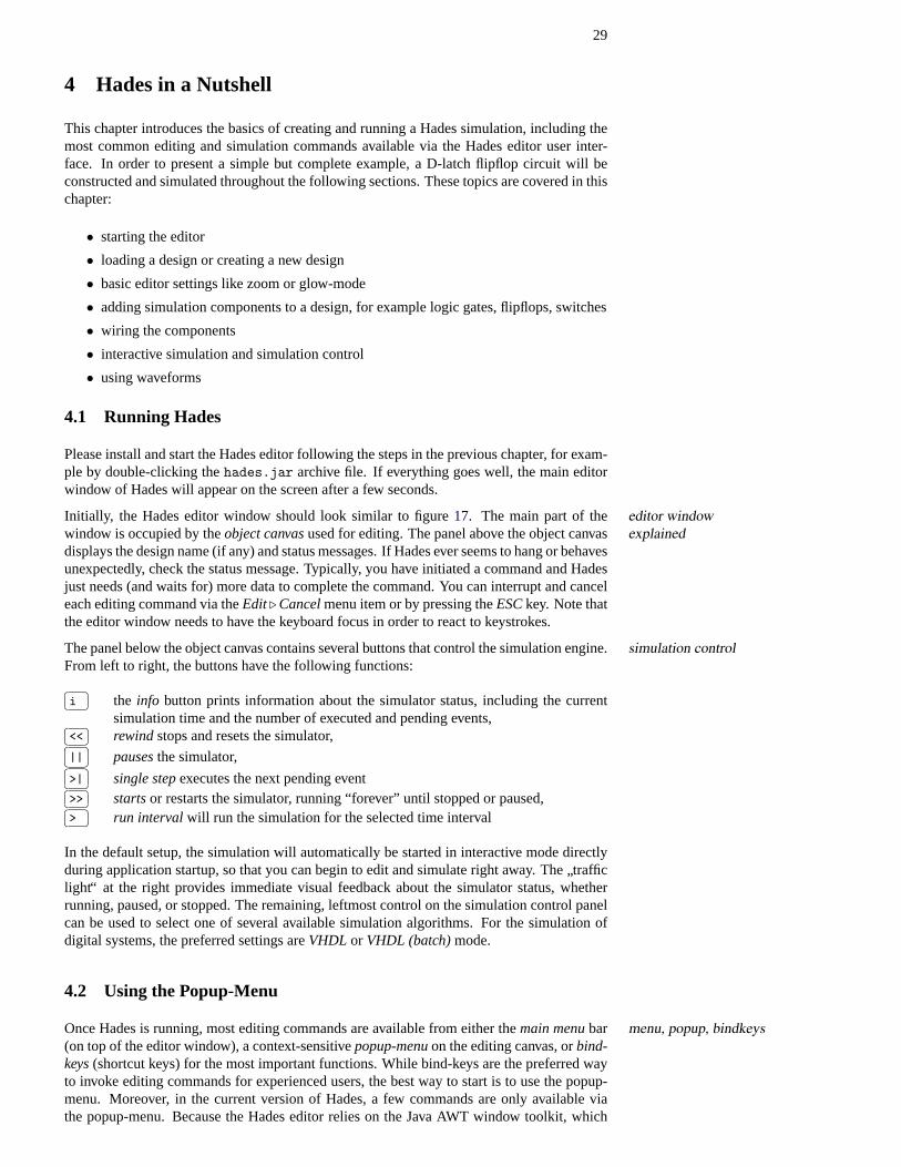
Initially, the Hades editor window should look similar to figure17. The main part of the editor windowexplainedwindow is occupied by theobject canvasused for editing. The panel above the object canvas
displays the design name (if any) and status messages. If Hades ever seems to hang or behavesunexpectedly, check the status message. Typically, you have initiated a command and Hadesjust needs (and waits for) more data to complete the command. You can interrupt and canceleach editing command via theEdit. Cancelmenu item or by pressing theESCkey. Note thatthe editor window needs to have the keyboard focus in order to react to keystrokes.
The panel below the object canvas contains several buttons that control the simulation engine.simulation controlFrom left to right, the buttons have the following functions:�� ��i the info button prints information about the simulator status, including the current
simulation time and the number of executed and pending events,�� ��<< rewindstops and resets the simulator,�� ��|| pausesthe simulator,�� ��>| single stepexecutes the next pending event�� ��>> startsor restarts the simulator, running “forever” until stopped or paused,�� ��> run intervalwill run the simulation for the selected time interval
In the default setup, the simulation will automatically be started in interactive mode directlyduring application startup, so that you can begin to edit and simulate right away. The
”traffic
light“ at the right provides immediate visual feedback about the simulator status, whetherrunning, paused, or stopped. The remaining, leftmost control on the simulation control panelcan be used to select one of several available simulation algorithms. For the simulation ofdigital systems, the preferred settings areVHDL or VHDL (batch)mode.
4.2 Using the Popup-Menu
Once Hades is running, most editing commands are available from either themain menubar menu, popup, bindkeys(on top of the editor window), a context-sensitivepopup-menuon the editing canvas, orbind-keys(shortcut keys) for the most important functions. While bind-keys are the preferred wayto invoke editing commands for experienced users, the best way to start is to use the popup-menu. Moreover, in the current version of Hades, a few commands are only available viathe popup-menu. Because the Hades editor relies on the Java AWT window toolkit, which
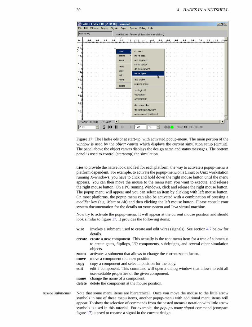
30 4 HADES IN A NUTSHELL
Figure 17: The Hades editor at start-up, with activated popup-menu. The main portion of thewindow is used by theobject canvaswhich displays the current simulation setup (circuit).The panel above the object canvas displays the design name and status messages. The bottompanel is used to control (start/stop) the simulation.
tries to provide the native look and feel for each platform, the way to activate a popup-menu isplatform dependent. For example, to activate the popup-menu on a Linux or Unix workstationrunning X-windows, you have to click and hold down the right mouse button until the menuappears. You can then move the mouse to the menu item you want to execute, and releasethe right mouse button. On a PC running Windows, click and release the right mouse button.The popup menu will appear and you can select an item by clicking with left mouse button.On most platforms, the popup menu can also be activated with a combination of pressing amodifierkey (e.g.Metaor Alt) and then clicking the left mouse button. Please consult yoursystem documentation for the details on your system and Java virtual machine.
Now try to activate the popup-menu. It will appear at the current mouse position and shouldlook similar to figure17. It provides the following items:
wire invokes a submenu used to create and edit wires (signals). See section4.7below fordetails.
create create a new component. This actually is the root menu item for a tree of submenusto create gates, flipflops, I/O components, subdesigns, and several other simulationobjects.
zoom activates a submenu that allows to change the current zoom factor.move move a component to a new position.copy copy a component and select a position for the copy.edit edit a component. This command will open a dialog window that allows to edit all
user-settable properties of the given component.name change the name of a component.delete delete the component at the mouse position.
Note that some menu items are hierarchical. Once you move the mouse to the little arrownested submenussymbols in one of these menu items, another popup-menu with additional menu items willappear. To show the selection of commands from the nested menus a notation with little arrowsymbols is used in this tutorial. For example, thepopup. name signalcommand (comparefigure17) is used to rename a signal in the current design.
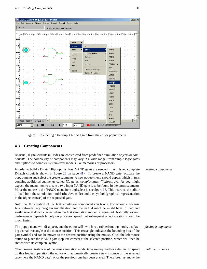
4.3 Creating Components 31
Figure 18: Selecting a two-input NAND gate from the editor popup-menu.
4.3 Creating Components
As usual, digital circuits in Hades are constructed from predefined simulation objects orcom-ponents. The complexity of components may vary in a wide range, from simple logic gatesand flipflops to complex system-level models like memories or processors.
In order to build a D-latch flipflop, just four NAND gates are needed. (the finished completecreating componentsD-latch circuit is shown in figure26 on page41). To create a NAND gate, activate thepopup-menu and select the create submenu. A new popup-menu should appear which in turncontains additional submenus calledIO, gates, complexgates, flipflops, etc. As you mightexpect, the menu item to create a two input NAND gate is to be found in thegatessubmenu.Move the mouse to theNAND2menu item and select it, see figure18. This instructs the editorto load both the simulation model (the Java code) and the symbol (graphical representationin the object canvas) of the requested gate.
Note that the creation of the first simulation component can take a few seconds, becauseJava enforces lazy program initialization and the virtual machine might have to load andverify several dozen classes when the first simulation model is requested. Naturally, overallperformance depends largely on processor speed, but subsequent object creation should bemuch faster.
The popup menu will disappear, and the editor will switch to a rubberbanding mode, display-placing componentsing a small rectangle at the mouse position. This rectangle indicates the bounding box of thegate symbol and can be moved to the desired position using the mouse. Click the left mousebutton to place the NAND gate (top left corner) at the selected position, which will then beshown with its complete symbol.
Often, several instances of the same simulation model type are required for a design. To speedmultiple instancesup this freqent operation, the editor will automatically create a new instance of the selectedtype (here the NAND gate), once the previous one has been placed. Therefore, just move the
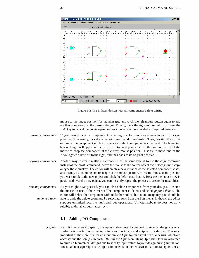
32 4 HADES IN A NUTSHELL
Figure 19: The D-latch design with all components before wiring
mouse to the target position for the next gate and click the left mouse button again to addanother component to the current design. Finally, click the right mouse button or press theESCkey to cancel thecreateoperation, as soon as you have created all required instances.
If you have dropped a component in a wrong position, you can always move it to a newmoving componentsposition. If necessary, cancel any ongoing command (likecreate). Then, position the mouseon one of the component symbol corners and selectpopup. movecommand. The boundingbox rectangle will appear at the mouse positon and you can move the component. Click themouse to drop the component at the current mouse position. Just try to move one of theNAND gates a little bit to the right, and then back to its original position.
Another way to create multiple components of the same type is to use thecopycommandcopying componentsinstead of thecreatecommand. Move the mouse to the source object and selectpopup. copyor type thec bindkey. The editor will create a new instance of the selected component class,and display its bounding box rectangle at the mouse position. Move the mouse to the positionyou want to place the new object and click the left mouse button. Because the mouse now ispositioned over the new object, you can instantly repeat the process to create the next object.
As you might have guessed, you can also delete components from your designs. Positiondeleting componentsthe mouse on one of the corners of the component to delete and selectpopup. delete. Theeditor will delete the component without further notice, but in an emergency you should beable to undo the delete command by selectingundofrom theEdit menu. In theory, the editorundo and redosupports unlimited recursiveundoandredooperations. Unfortunately,undodoes not workreliably under all circumstances yet.
4.4 Adding I/O-Components
Next, it is necessary to specify the inputs and outputs of your design. As most design systems,I/O pinsHades uses special components to indicate the inputs and outputs of a design. The mostimportant of these areIpin for an input pin andOpin for an output pin of a design, which areaccessed via thepopup. create. IO . Ipin andOpinmenu items. Ipin and Opin are also usedto build up hierarchical designs and to specify input values to your design during simulation.The D-latch design requires two Ipin components for the D (data) and C (clock) inputs, and an
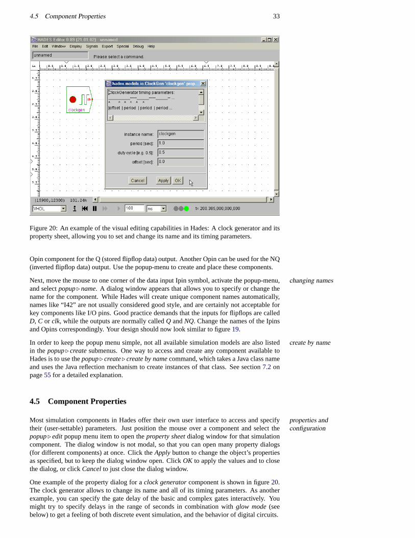
4.5 Component Properties 33
Figure 20: An example of the visual editing capabilities in Hades: A clock generator and itsproperty sheet, allowing you to set and change its name and its timing parameters.
Opin component for the Q (stored flipflop data) output. Another Opin can be used for the NQ(inverted flipflop data) output. Use the popup-menu to create and place these components.
Next, move the mouse to one corner of the data input Ipin symbol, activate the popup-menu,changing namesand selectpopup. name. A dialog window appears that allows you to specify or change thename for the component. While Hades will create unique component names automatically,names like “I42” are not usually considered good style, and are certainly not acceptable forkey components like I/O pins. Good practice demands that the inputs for flipflops are calledD, C or clk, while the outputs are normally calledQ andNQ. Change the names of the Ipinsand Opins correspondingly. Your design should now look similar to figure19.
In order to keep the popup menu simple, not all available simulation models are also listedcreate by namein the popup. createsubmenus. One way to access and create any component available toHades is to use thepopup. create. create by namecommand, which takes a Java class nameand uses the Java reflection mechanism to create instances of that class. See section7.2 onpage55 for a detailed explanation.
4.5 Component Properties
Most simulation components in Hades offer their own user interface to access and specifyproperties andconfigurationtheir (user-settable) parameters. Just position the mouse over a component and select the
popup. edit popup menu item to open theproperty sheetdialog window for that simulationcomponent. The dialog window is not modal, so that you can open many property dialogs(for different components) at once. Click theApplybutton to change the object’s propertiesas specified, but to keep the dialog window open. ClickOK to apply the values and to closethe dialog, or clickCancelto just close the dialog window.
One example of the property dialog for aclock generatorcomponent is shown in figure20.The clock generator allows to change its name and all of its timing parameters. As anotherexample, you can specify the gate delay of the basic and complex gates interactively. Youmight try to specify delays in the range of seconds in combination withglow mode(seebelow) to get a feeling of both discrete event simulation, and the behavior of digital circuits.
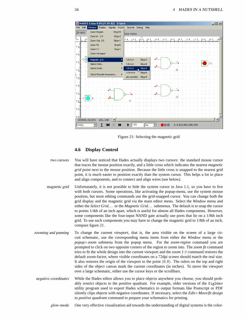
34 4 HADES IN A NUTSHELL
Figure 21: Selecting the magnetic grid
4.6 Display Control
You will have noticed that Hades actually displays two cursors: the standard mouse cursortwo cursorsthat traces the mouse position exactly, and a little cross which indicates the nearestmagneticgrid point next to the mouse position. Because the little cross is snapped to the nearest gridpoint, it is much easier to position exactly than the system cursor. This helps a lot to placeand align components, and to connect and align wires (see below).
Unfortunately, it is not possible to hide the system cursor in Java 1.1, so you have to livemagnetic gridwith both cursors. Some operations, like activating the popup-menu, use the system mouseposition, but most editing commands use the grid-snapped cursor. You can change both thegrid display and the magnetic grid via the main editor menu. Select theWindowmenu andeither theSelect Grid. . .or theMagnetic Grid. . .submenus. The default is to snap the cursorto points 1/4th of an inch apart, which is useful for almost all Hades components. However,some components like the four-input NAND gate actually use ports that lie on a 1/8th inchgrid. To use such components you may have to change the magnetic grid to 1/8th of an inch,compare figure21.
To change the currentviewport, that is, the area visible on the screen of a large cir-zooming and panningcuit schematic, use the corresponding menu items from either theWindow menu or thepopup. zoomsubmenu from the popup menu. For thezoom-regioncommand you areprompted to click on two opposite corners of the region to zoom into. Thezoom fitcommandtries to fit the whole design into the current viewport and thezoom 1:1command restores thedefault zoom-factor, where visible coordinates on a 72dpi screen should match the real size.It also restores the origin of the viewport to the point(0,0). The rulers on the top and rightsides of the object canvas mark the current coordinates (in inches). To move the viewportover a large schematic, either use the cursor keys or the scrollbars.
While the Hades editor allows you to place objects anywhere you choose, you should prob-negative coordinatesably restrict objects to the positive quadrant. For example, older versions of thefig2devutility program used to export Hades schematics to output formats like Postscript or PDFsilently clips objects with negative coordinates. If necessary, select theEdit. Move/fit designto positive quadrantcommand to prepare your schematics for printing.
One very effective visualization aid towards the understanding of digital systems is the color-glow-mode
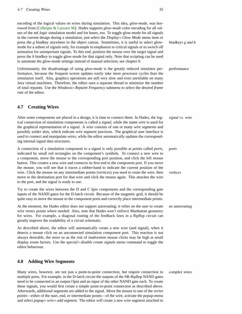
4.7 Creating Wires 35
encoding of the logical values on wires during simulation. This idea,glow-mode, was bor-rowed from [Gillespie & Lazzaro 96]. Hades supportsglow-modecolor encoding for all val-ues of thestd logic simulation model and for buses, too. To toggle glow-mode for all signalsin the current design during a simulation, just select theDisplay. Glow Modemenu item orpress theg bindkey anywhere in the object canvas. Sometimes, it is useful to select glow-bindkeys g and hmode for a subset of signals only, for example to emphasize to critical signals or to switch offanimation for unimportant signals. To this end, position the mouse over the target signal andpress theh bindkey to toggle glow-mode for that signal only. Note that scripting can be usedto automate the glow-mode settings instead of manual selection, see chapter8.
Unfortunately, the disadvantage of usingglow-modeis the greatly reduced simulator per-performanceformance, because the frequent screen updates easily take more processor cycles than thesimulation itself. Also, graphics operations are still very slow and even unreliable on manyJava virtual machines. Therefore, the editor uses a separate thread to minimize the numberof total repaints. Use theWindows. Repaint Frequencysubmenu to select the desiredframerateof the editor.
4.7 Creating Wires
After some components are placed in a design, it is time to connect them. In Hades, the log-signal vs. wireical connection of simulation components is called asignal, while the namewire is used forthe graphical representation of a signal. A wire consists of one or manywire segmentsandpossiblysolder dots, which indicatewire segmentjunctions. The graphical user interface isused to connect and manipulatewires, while the editor automatically updates the correspond-ing internal signal data structures.
A connection of a simulation component to a signal is only possible at points calledports, portsindicated by small red rectangles on the component’s symbols. To connect a new wire toa component, move the mouse to the corresponding port position, and click the left mousebutton. This creates a new wire and connects its first end to the component port. If you movethe mouse, you will see that it traces a rubber-band to indicate the current position of thewire. Click the mouse on any intermediate points (vertices) you need to route the wire, then verticesmove to the destination port for that wire and click the mouse again. This attaches the wireto the port, and the signal is ready to use.
Try to create the wires between theD andC Ipin components and the corresponding gateinputs of the NAND gates for the D-latch circuit. Because of the magnetic grid, it should bequite easy to move the mouse to the component ports and correctly place intermediate points.
At the moment, the Hades editor does not support autorouting; it relies on the user to createno autoroutingwire vertex points where needed. Also, note that Hades won’t enforce Manhattan geometryfor wires. For example, a diagonal routing of the feedback lines in a flipflop circuit cangreatly improve the readability of a circuit schematic.
As described above, the editor will automatically create a new wire (and signal), when itdetects a mouse click on an unconnected simulation component port. This reaction is notalways desirable, the more so as the risk of inadvertent mouse clicks may be high at smalldisplay zoom factors. Use thespecial. disable create signalsmenu command to toggle theeditor behaviour.
4.8 Adding Wire Segments
Many wires, however, are not just a point-to-point connection, but require connection tocomplex wiresmultiple ports. For example, in the D-latch circuit the outputs of the SR-flipflop NAND gatesneed to be connected to an output Opin and an input of the other NAND gate each. To createthese signals, you would first create a simple point-to-point connection as described above.Afterwards, additional segments are added to the signal. Move the mouse to one of thevertexpoints—either of the start, end, or intermediate points—of the wire, activate the popup-menuand selectpopup. wire. add segment. The editor will create a new wire segment attached to
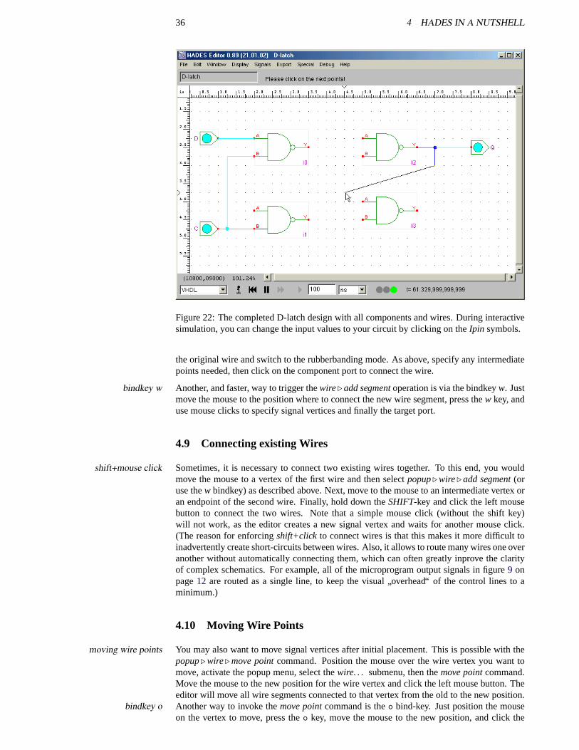
36 4 HADES IN A NUTSHELL
Figure 22: The completed D-latch design with all components and wires. During interactivesimulation, you can change the input values to your circuit by clicking on theIpin symbols.
the original wire and switch to the rubberbanding mode. As above, specify any intermediatepoints needed, then click on the component port to connect the wire.
Another, and faster, way to trigger thewire. add segmentoperation is via the bindkeyw. Justbindkey wmove the mouse to the position where to connect the new wire segment, press thew key, anduse mouse clicks to specify signal vertices and finally the target port.
4.9 Connecting existing Wires
Sometimes, it is necessary to connect two existing wires together. To this end, you wouldshift+mouse clickmove the mouse to a vertex of the first wire and then selectpopup. wire. add segment(oruse thew bindkey) as described above. Next, move to the mouse to an intermediate vertex oran endpoint of the second wire. Finally, hold down theSHIFT-key and click the left mousebutton to connect the two wires. Note that a simple mouse click (without the shift key)will not work, as the editor creates a new signal vertex and waits for another mouse click.(The reason for enforcingshift+click to connect wires is that this makes it more difficult toinadvertently create short-circuits between wires. Also, it allows to route many wires one overanother without automatically connecting them, which can often greatly inprove the clarityof complex schematics. For example, all of the microprogram output signals in figure9 onpage12 are routed as a single line, to keep the visual
”overhead“ of the control lines to a
minimum.)
4.10 Moving Wire Points
You may also want to move signal vertices after initial placement. This is possible with themoving wire pointspopup. wire. move pointcommand. Position the mouse over the wire vertex you want tomove, activate the popup menu, select thewire. . . submenu, then themove pointcommand.Move the mouse to the new position for the wire vertex and click the left mouse button. Theeditor will move all wire segments connected to that vertex from the old to the new position.Another way to invoke themove pointcommand is theo bind-key. Just position the mousebindkey oon the vertex to move, press theo key, move the mouse to the new position, and click the
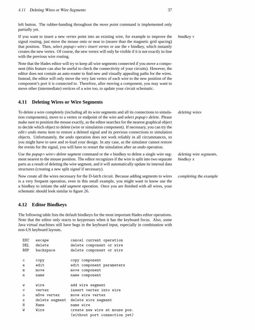
4.11 Deleting Wires or Wire Segments 37
left button. The rubber-banding throughout themove pointcommand is implemented onlypartially yet.
If you want to insert a newvertexpoint into an existing wire, for example to improve thebindkey vsignal routing, just move the mouse onto or near to (nearer than the magnetic grid spacing)that position. Then, selectpopup. wire. insert vertexor use thev bindkey, which instantlycreates the new vertex. Of course, the new vertex will only be visible if it is not exactly in-linewith the previous wire routing.
Note that the Hades editor will try to keep all wire segments connected if you move a compo-nent (this feature can also be useful to check the connectivity of your circuits). However, theeditor does not contain an auto-router to find new and visually appealing paths for the wires.Instead, the editor will only move the very last vertex of each wire to the new position of thecomponent’s port it is connected to. Therefore, after moving a component, you may want tomove other (intermediate) vertices of a wire too, to update your circuit schematic.
4.11 Deleting Wires or Wire Segments
To delete a wire completely (including all its wire segments and all its connections to simula-deleting wirestion components), move to a vertex or endpoint of the wire and selectpopup. delete. Pleasemake sure to position the mouse exactly, as the editor searches for the nearest graphical objectto decide which object to delete (wire or simulation component). If necessary, you can try theedit. undomenu item to restore a deleted signal and its previous connections to simulationobjects. Unfortunately, theundooperation does not work reliably in all circumstances, soyou might have to save and re-load your design. In any case, as the simulator cannot restorethe events for the signal, you will have to restart the simulation after anundooperation.
Use thepopup. wire. delete segmentcommand or thex bindkey to delete a single wire seg- deleting wire segments,bindkey xment nearest to the mouse position. The editor recognizes if the wire is split into two separate
parts as a result of deleting the wire segment, and it will automatically update its internal datastructures (creating a new splitsignal if necessary).
Now create all the wires necessary for the D-latch circuit. Because adding segments to wirescompleting the exampleis a very frequent operation, even in this small example, you might want to know use thew bindkey to initiate theadd segmentoperation. Once you are finished with all wires, yourschematic should look similar to figure26.
4.12 Editor Bindkeys
The following table lists the default bindkeys for the most important Hades editor operations.Note that the editor only reacts to keypresses when it has the keyboard focus. Also, someJava virtual machines still have bugs in the keyboard input, especially in combination withnon-US keyboard layouts.
ESC escape cancel current operationDEL delete delete component or wireBSP backspace delete component or wire
c copy copy componente edit edit component parametersm move move componentn name name component
w wire add wire segmentv vertex insert vertex into wireo mOve vertex move wire vertexx delete segment delete wire segmentN Name name wireW Wire create new wire at mouse pos.
(without port connection yet)
38 4 HADES IN A NUTSHELL
4.13 Loading and Saving Designs
This is a good time to save your design. At the moment, Hades stores design data as plainsaving designsASCII text files, one file perdesignor schematic, which means that you can also use yourfavorite text editor to view or modify the design files. Because you did not specify a namefor the design until now, you should selectSave As. . .from theFile menu which will openthe standard file selector dialog. Therefore, enter a suitable filename, e.g.dlatch.hds, andclick the OK button. For a larger project with many subdesigns, you might want to createand use subdirectories. By convention we use the extension.hds for Hades design files,which matches the German pronunciation of Hades. Moreover, we use filenames of the form.hds extensiondesignname.sym for the Hades symbol corresponding to a designdesignname.hds.
Once you have saved your design, the editor will remember the filename, so that you canuse theFile . Savemenu command to save the design again. TheSaveoperation doesnot overwrite the previous version of a design file, but automatically renames the exist-ing file before saving the current design. The naming pattern used for the backup files isdesignname.hds_<number>. For example, the first two backups ofdlatch.hdswill be calleddlatch.hds1 anddlatch.hds2. By the way, the default filename isunnamed.hds in the cur-rent working directory.
As you have saved your design now, you might as well try to read it back. Select theNewloading designsmenu item from theFile menu, which instructs Hades to delete all current editor objects andstart a new design. Now select theOpenmenu item from theFile menu, which again willopen a file selector dialog. Enter the file name for your D-latch design and clickOK.
Despite the overhead of parsing the design files and object creation, loading a small designfile should only take a few seconds on current PCs or workstations. Naturally, loading largerhierarchical circuits with many subdesigns and thousands of simulation components can takemuch longer, especially when the Java virtual machine runs short of memory and needs tostart garbage collections during circuit initialization.
4.14 Digital Simulation and StdLogic1164
While the Hades framework can be used for all types of discrete-event simulation, most ofmodeling issuesthe available simulation components circuit as well as the different simulation engines aretargeted towards digital circuit simulation. The goal of every simulation is to study the be-haviour of some real system from a set of idealised models. This allows for a variety ofdescriptions with greatly differing levels of abstraction and detail. One very successful ab-straction is switch-level simulation, where the complex, non-linear and time-continous be-haviour of electronical circuits is modeled with a set of discrete logical values that change atdiscrete times.
The most simple simulation model is the Boolean algrebra with its two logical values0 and1 and the well-known switching functions (AND, OR, etc.). Unfortunately, this model oftenis too restrained; for example it is impossible to model important situations like short-circuitsor undefined input values. Therefore, multi-level logic systems are often used to model andsimulate digital circuits. Several tools support a three-level model with the values0, 1, andX, where theX level is included to model undefined values during circuit initialization or toindicate errors like a bus with multiple confliciting drivers.
However, even more complex logic systems are required to model situations like open-std logiccollector output gates or buses with tri-state drivers and pullup resistors. Therefore, all gate-level simulation components in Hades use the de-facto industry standard logic model, thenine-valuedstd logic system [IEEE 93b] used in the VHDL simulation language [IEEE-93a].Please skip the next few paragraphs if you are already familiar with digital simulation and thestd logic multilevel logic.
Figure23 shows the nine logic values fromstd logic and their meanings; these are imple-mented in classhades.models.StdLogic1164together with the basic logical operations. Atthe start of a simulation, all signals and gates are initialized to theU state (undefined) inStdLogic1164. Because any logic gates will propagateU values if they receiveU values, the
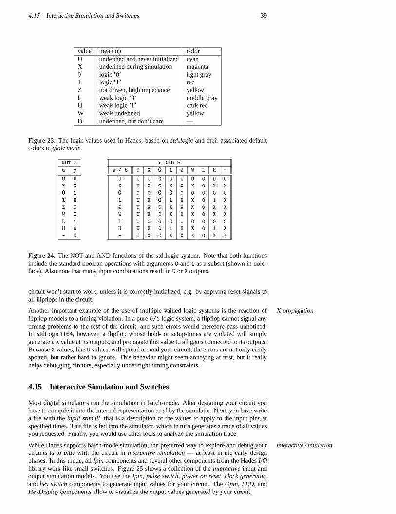
4.15 Interactive Simulation and Switches 39
value meaning colorU undefined and never initializedcyanX undefined during simulation magenta0 logic ’0’ light gray1 logic ’1’ redZ not driven, high impedance yellowL weak logic ’0’ middle grayH weak logic ’1’ dark redW weak undefined yellowD undefined, but don’t care —
Figure 23: The logic values used in Hades, based onstd logic and their associated defaultcolors inglow mode.
NOT a
a y
U U
X X
000 111111 000Z X
W X
L 1
H 0
- X
a AND b
a / b U X 000 111 Z W L H -
U U U 0 U U U 0 U U
X U X 0 X X X 0 X X
000 0 0 000 000 0 0 0 0 0
111 U X 000 111 X X 0 1 X
Z U X 0 X X X 0 X X
W U X 0 X X X 0 X X
L 0 0 0 0 0 0 0 0 0
H U X 0 1 X X 0 1 X
- U X 0 X X X 0 X X
Figure 24: The NOT and AND functions of the stdlogic system. Note that both functionsinclude the standard boolean operations with arguments0 and1 as a subset (shown in bold-face). Also note that many input combinations result inU or X outputs.
circuit won’t start to work, unless it is correctly initialized, e.g. by applying reset signals toall flipflops in the circuit.
Another important example of the use of multiple valued logic systems is the reaction ofX propagationflipflop models to a timing violation. In a pure0/1 logic system, a flipflop cannot signal anytiming problems to the rest of the circuit, and such errors would therefore pass unnoticed.In StdLogic1164, however, a flipflop whose hold- or setup-times are violated will simplygenerate aX value at its outputs, and propagate this value to all gates connected to its outputs.BecauseX values, likeU values, will spread around your circuit, the errors are not only easilyspotted, but rather hard to ignore. This behavior might seem annoying at first, but it reallyhelps debugging circuits, especially under tight timing constraints.
4.15 Interactive Simulation and Switches
Most digital simulators run the simulation in batch-mode. After designing your circuit youhave to compile it into the internal representation used by the simulator. Next, you have writea file with theinput stimuli, that is a description of the values to apply to the input pins atspecified times. This file is fed into the simulator, which in turn generates a trace of all valuesyou requested. Finally, you would use other tools to analyze the simulation trace.
While Hades supports batch-mode simulation, the preferred way to explore and debug yourinteractive simulationcircuits is toplay with the circuit in interactive simulation— at least in the early designphases. In this mode, allIpin components and several other components from the HadesI/Olibrary work like small switches. Figure25 shows a collection of theinteractiveinput andoutput simulation models. You use theIpin, pulse switch, power on reset, clock generator,andhex switchcomponents to generate input values for your circuit. TheOpin, LED, andHexDisplaycomponents allow to visualize the output values generated by your circuit.
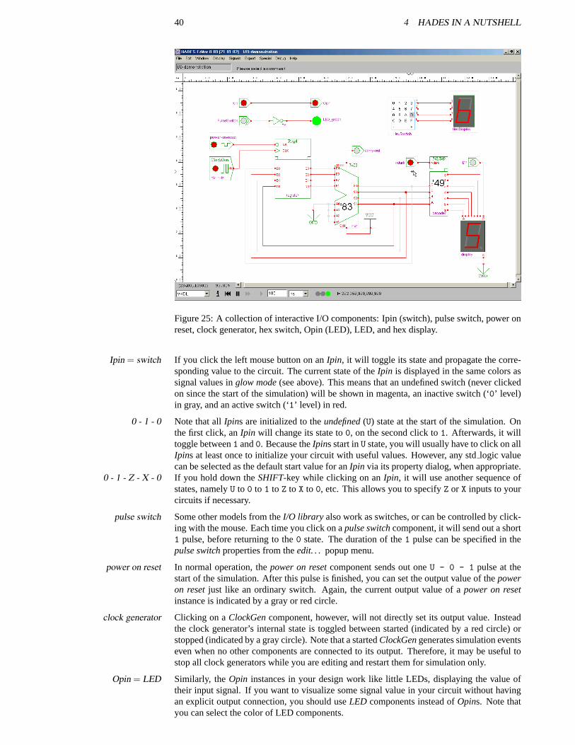
40 4 HADES IN A NUTSHELL
Figure 25: A collection of interactive I/O components: Ipin (switch), pulse switch, power onreset, clock generator, hex switch, Opin (LED), LED, and hex display.
If you click the left mouse button on anIpin, it will toggle its state and propagate the corre-Ipin = switchsponding value to the circuit. The current state of theIpin is displayed in the same colors assignal values inglow mode(see above). This means that an undefined switch (never clickedon since the start of the simulation) will be shown in magenta, an inactive switch (‘0’ level)in gray, and an active switch (‘1’ level) in red.
Note that allIpins are initialized to theundefined(U) state at the start of the simulation. On0 - 1 - 0the first click, anIpin will change its state to0, on the second click to1. Afterwards, it willtoggle between1 and0. Because theIpins start inU state, you will usually have to click on allIpins at least once to initialize your circuit with useful values. However, any stdlogic valuecan be selected as the default start value for anIpin via its property dialog, when appropriate.If you hold down theSHIFT-key while clicking on anIpin, it will use another sequence of0 - 1 - Z - X - 0states, namelyU to 0 to 1 to Z to X to 0, etc. This allows you to specifyZ or X inputs to yourcircuits if necessary.
Some other models from theI/O library also work as switches, or can be controlled by click-pulse switching with the mouse. Each time you click on apulse switchcomponent, it will send out a short1 pulse, before returning to the0 state. The duration of the1 pulse can be specified in thepulse switchproperties from theedit. . . popup menu.
In normal operation, thepower on resetcomponent sends out oneU - 0 - 1 pulse at thepower on resetstart of the simulation. After this pulse is finished, you can set the output value of thepoweron resetjust like an ordinary switch. Again, the current output value of apower on resetinstance is indicated by a gray or red circle.
Clicking on aClockGencomponent, however, will not directly set its output value. Insteadclock generatorthe clock generator’s internal state is toggled between started (indicated by a red circle) orstopped (indicated by a gray circle). Note that a startedClockGengenerates simulation eventseven when no other components are connected to its output. Therefore, it may be useful tostop all clock generators while you are editing and restart them for simulation only.
Similarly, theOpin instances in your design work like little LEDs, displaying the value ofOpin = LEDtheir input signal. If you want to visualize some signal value in your circuit without havingan explicit output connection, you should useLED components instead ofOpins. Note thatyou can select the color of LED components.
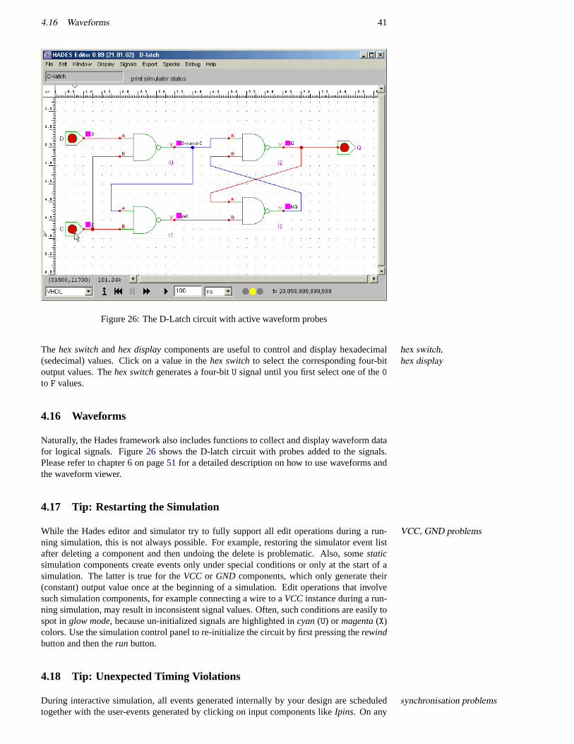
4.16 Waveforms 41
Figure 26: The D-Latch circuit with active waveform probes
The hex switchandhex displaycomponents are useful to control and display hexadecimalhex switch,hex display(sedecimal) values. Click on a value in thehex switchto select the corresponding four-bit
output values. Thehex switchgenerates a four-bitU signal until you first select one of the0to F values.
4.16 Waveforms
Naturally, the Hades framework also includes functions to collect and display waveform datafor logical signals. Figure26 shows the D-latch circuit with probes added to the signals.Please refer to chapter6 on page51 for a detailed description on how to use waveforms andthe waveform viewer.
4.17 Tip: Restarting the Simulation
While the Hades editor and simulator try to fully support all edit operations during a run-VCC, GND problemsning simulation, this is not always possible. For example, restoring the simulator event listafter deleting a component and then undoing the delete is problematic. Also, somestaticsimulation components create events only under special conditions or only at the start of asimulation. The latter is true for theVCC or GND components, which only generate their(constant) output value once at the beginning of a simulation. Edit operations that involvesuch simulation components, for example connecting a wire to aVCC instance during a run-ning simulation, may result in inconsistent signal values. Often, such conditions are easily tospot inglow mode, because un-initialized signals are highlighted incyan(U) or magenta(X)colors. Use the simulation control panel to re-initialize the circuit by first pressing therewindbutton and then therun button.
4.18 Tip: Unexpected Timing Violations
During interactive simulation, all events generated internally by your design are scheduledsynchronisation problemstogether with the user-events generated by clicking on input components likeIpins. On any

42 4 HADES IN A NUTSHELL
user-generated event, the current simulation time is used as its time stamp. this behaviour mayresult in unexpected faults in your simulation wheneven the events feeds the input of a flipflopor similar component, which might detect a setup- or hold-time violation with respect to itsclock signal. Usually, the flipflop will then generate aX value on its output which propagatesto the rest of the circuit.
If such a timing violation occurs, you may have to re-initialize the flipflops concerned or eventhe whole circuit, and to restart part of your simulation. Unfortunately, there is no simplesolution to this problem except to use batch-mode simulation, where all input changes occuron predefined times with respect to the simulation time. Note that real circuits also sufferfrom these timing problesm, because the timing of input changes can never be guaranteed.However, real flipflops won’t signal the timing problem with a definedX state, but may enteran undefinedmetastablestate with unpredictable duration and output value.
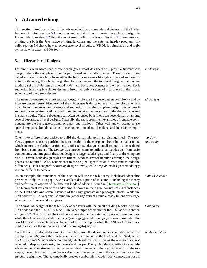
43
5 Advanced editing
This section introduces a few of the advanced editor commands and features of the Hadesframework. First, section5.1 motivates and explains how to create hierarchical designs inHades. Next, section5.2 lists the most useful editor bindkeys. Section5.3 demonstratesprinting via both the Java native printing functions and the external fig2dev program. Fi-nally, section5.4 shows how to export gate-level circuits to VHDL for simulation and logicsynthesis with external EDA tools.
5.1 Hierarchical Designs
For circuits with more than a few dozen gates, most designers will prefer ahierarchical subdesignsdesign, where the complete circuit is partitioned into smaller blocks. These blocks, oftencalledsubdesigns, are built from either the basic components like gates or nested subdesignsin turn. Obviously, the whole design then forms a tree with the top-level design at the root, anarbitrary set of subdesigns as internal nodes, and basic components as the tree’s leaves. Eachsubdesign is a complete Hades design in itself, but only it’ssymbolis displayed in the circuitschematic of the parent design.
The main advantages of a hierarchical design style are to reduce design complexity and toadvantagesincrease design reuse. First, each of the subdesigns is designed as a separate circuit, with amuch lower number of components and subdesigns than the complete design. Second, eachsubdesign can be simulated for itself, catching most errors very soon in the design cycle andin small circuits. Third, subdesigns can often be reused both in one top-level design or amongseveral separate top-level designs. Naturally, the most prominent examples of reusable com-ponents are the basic gates, complex gates, and flipflops. Other well-known examples arespecial registers, functional units like counters, encoders, decoders, and interface compo-nents.
Often, two different approaches to build the design hierarchy are distinguished. Thetop- top-downbottom-updownapproach starts to partition the specification of the complete circuit into smaller units,
which in turn are further partitioned, until each subdesign is small enough to be realizedfrom basic components. Thebottom-upapproach starts to build small subdesigns from basiccomponents, and integrates these subdesigns to larger subdesigns, and finally to the completecircuit. Often, both design styles are mixed, because several iterations through the designphases are required. Also, refinements to the original specification further tend to hide thedifferences. Hades supportsbottom-updesign directly, while atop-downdesign methodologyis more difficult to achieve.
As an example, the remainder of this section will use the 8-bit carry lookahead adder first8-bit CLA adderpresented in figure4 on page7. An excellent description of this circuit including the theoryand performance aspects of the different kinds of adders is found in [Hennessy & Patterson].The hierarchical version of the adder circuit shown in the figure consists of eight instancesof the 1-bit adder and seven instances of the carry generate and propagate block. While the8-bit adder is still a very small circuit, theflat design variant would already fill one very largeschematic with several dozen gates.
Thebottom updesign of the 8-bit CLA adder starts with the small building blocks, here the1-bit adder1-bit adder and the 1-bit CLA block. The very simple schematic for the 1-bit adder is shownin figure 27. The Ipin switches and connectors define the external inputsain, bin, andcin,while theOpin connectors define thesi (sum),gi (generate) andpi (propagate) outputs. Thetwo XOR gates calculate the one bit sum of the three inputs while the AND or OR gates areused to calculate thegi (generate) andpi (propagate) signals.
Once the above 1-bit adder circuit is complete, save the design under a suitable name, forsymbol creationexamplesum.hds, using theFile . Save asmenu command in the Hades editor. Next, selecttheEdit. Create Symboleditor command, which automatically creates thegraphical symbolrequired to display a subdesign in the toplevel design. The symbol data is written to a text filewhose name is constructed from the current design name and the.symextension. In the ex-ample, the symbol file forsum.hdsis calledsum.symand written to the same directory as thesum.hdsdesign file. The automatically created symbol file includes port connections for all
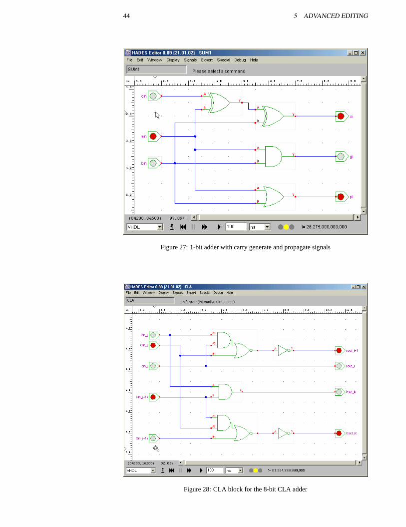
44 5 ADVANCED EDITING
Figure 27: 1-bit adder with carry generate and propagate signals
Figure 28: CLA block for the 8-bit CLA adder
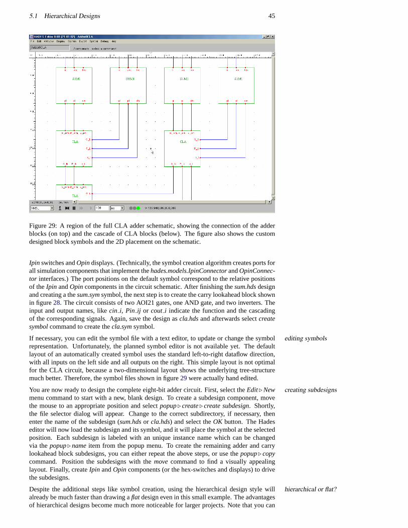
5.1 Hierarchical Designs 45
Figure 29: A region of the full CLA adder schematic, showing the connection of the adderblocks (on top) and the cascade of CLA blocks (below). The figure also shows the customdesigned block symbols and the 2D placement on the schematic.
Ipin switches andOpindisplays. (Technically, the symbol creation algorithm creates ports forall simulation components that implement thehades.models.IpinConnectorandOpinConnec-tor interfaces.) The port positions on the default symbol correspond to the relative positionsof theIpin andOpincomponents in the circuit schematic. After finishing thesum.hdsdesignand creating a thesum.symsymbol, the next step is to create the carry lookahead block shownin figure28. The circuit consists of two AOI21 gates, one AND gate, and two inverters. Theinput and output names, likecin i, Pin ij or cout i indicate the function and the cascadingof the corresponding signals. Again, save the design ascla.hdsand afterwards selectcreatesymbolcommand to create thecla.symsymbol.
If necessary, you can edit the symbol file with a text editor, to update or change the symbolediting symbolsrepresentation. Unfortunately, the planned symbol editor is not available yet. The defaultlayout of an automatically created symbol uses the standard left-to-right dataflow direction,with all inputs on the left side and all outputs on the right. This simple layout is not optimalfor the CLA circuit, because a two-dimensional layout shows the underlying tree-structuremuch better. Therefore, the symbol files shown in figure29were actually hand edited.
You are now ready to design the complete eight-bit adder circuit. First, select theEdit. New creating subdesignsmenu command to start with a new, blank design. To create a subdesign component, movethe mouse to an appropriate position and selectpopup. create. create subdesign. Shortly,the file selector dialog will appear. Change to the correct subdirectory, if necessary, thenenter the name of the subdesign (sum.hdsor cla.hds) and select theOK button. The Hadeseditor will now load the subdesign and its symbol, and it will place the symbol at the selectedposition. Each subdesign is labeled with an unique instance name which can be changedvia thepopup. nameitem from the popup menu. To create the remaining adder and carrylookahead block subdesigns, you can either repeat the above steps, or use thepopup. copycommand. Position the subdesigns with themovecommand to find a visually appealinglayout. Finally, createIpin andOpin components (or the hex-switches and displays) to drivethe subdesigns.
Despite the additional steps like symbol creation, using the hierarchical design style willhierarchical or flat?already be much faster than drawing aflat design even in this small example. The advantagesof hierarchical designs become much more noticeable for larger projects. Note that you can
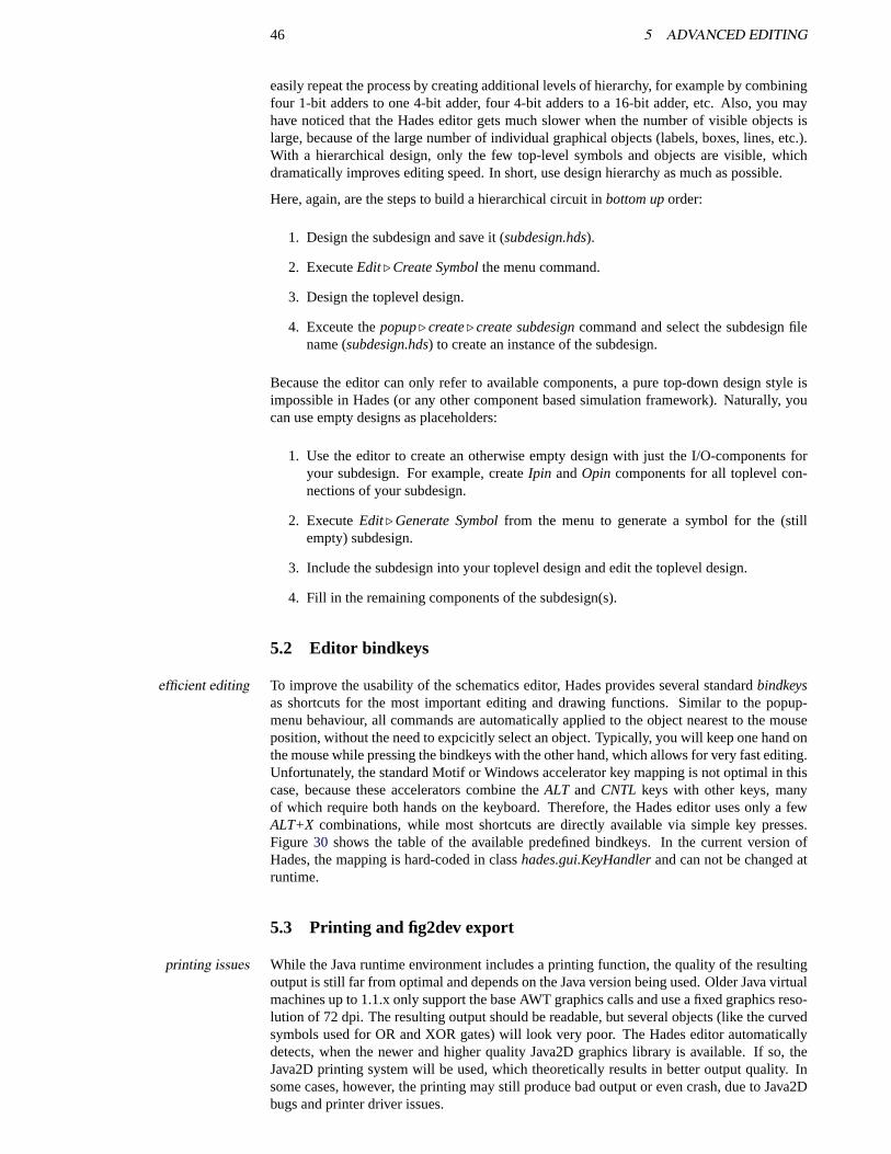
46 5 ADVANCED EDITING
easily repeat the process by creating additional levels of hierarchy, for example by combiningfour 1-bit adders to one 4-bit adder, four 4-bit adders to a 16-bit adder, etc. Also, you mayhave noticed that the Hades editor gets much slower when the number of visible objects islarge, because of the large number of individual graphical objects (labels, boxes, lines, etc.).With a hierarchical design, only the few top-level symbols and objects are visible, whichdramatically improves editing speed. In short, use design hierarchy as much as possible.
Here, again, are the steps to build a hierarchical circuit inbottom uporder:
1. Design the subdesign and save it (subdesign.hds).
2. ExecuteEdit. Create Symbolthe menu command.
3. Design the toplevel design.
4. Exceute thepopup. create. create subdesigncommand and select the subdesign filename (subdesign.hds) to create an instance of the subdesign.
Because the editor can only refer to available components, a pure top-down design style isimpossible in Hades (or any other component based simulation framework). Naturally, youcan use empty designs as placeholders:
1. Use the editor to create an otherwise empty design with just the I/O-components foryour subdesign. For example, createIpin andOpin components for all toplevel con-nections of your subdesign.
2. ExecuteEdit. Generate Symbolfrom the menu to generate a symbol for the (stillempty) subdesign.
3. Include the subdesign into your toplevel design and edit the toplevel design.
4. Fill in the remaining components of the subdesign(s).
5.2 Editor bindkeys
To improve the usability of the schematics editor, Hades provides several standardbindkeysefficient editingas shortcuts for the most important editing and drawing functions. Similar to the popup-menu behaviour, all commands are automatically applied to the object nearest to the mouseposition, without the need to expcicitly select an object. Typically, you will keep one hand onthe mouse while pressing the bindkeys with the other hand, which allows for very fast editing.Unfortunately, the standard Motif or Windows accelerator key mapping is not optimal in thiscase, because these accelerators combine theALT and CNTL keys with other keys, manyof which require both hands on the keyboard. Therefore, the Hades editor uses only a fewALT+X combinations, while most shortcuts are directly available via simple key presses.Figure 30 shows the table of the available predefined bindkeys. In the current version ofHades, the mapping is hard-coded in classhades.gui.KeyHandlerand can not be changed atruntime.
5.3 Printing and fig2dev export
While the Java runtime environment includes a printing function, the quality of the resultingprinting issuesoutput is still far from optimal and depends on the Java version being used. Older Java virtualmachines up to 1.1.x only support the base AWT graphics calls and use a fixed graphics reso-lution of 72 dpi. The resulting output should be readable, but several objects (like the curvedsymbols used for OR and XOR gates) will look very poor. The Hades editor automaticallydetects, when the newer and higher quality Java2D graphics library is available. If so, theJava2D printing system will be used, which theoretically results in better output quality. Insome cases, however, the printing may still produce bad output or even crash, due to Java2Dbugs and printer driver issues.
5.3 Printing and fig2dev export 47
Key Function0 set a signal to ’0’ level1 set a signal to ’1’ levelc copy a componente edit a component’s propertiesf zoom fitF zoom full (100%)g toggle glow mode (all signals)h toggle glow mode (one signal)I create an Ipin componentm move a componentM move a signal vertexN change a signal namen change a component nameo move a signal vertexO create an Opin componentp add a probe to a signalP delete a probe from a signalr force a redrawU undo the last commandv insert a new vertex into a wirew create a wire segment attached to a signal vertexW create a wire (possibly unconnected) at the mouse positionx delete a wire segmenty zoom out (71%)z zoom out, centered (71%)Z zoom in, centered (141%)BSP, DEL delete a component/wireESC interrupt and cancel any command
Figure 30: Important bindkeys in Hades, sorted alphabetically
To test the Java native printing, simply select theFile . Print menu command from the editormenu bar. This will open the platform specific print options dialog, which allows to selectthe printer, paper size and orientation, etc. Click theOK button in the dialog window to startthe printing.
The recommended way to print Hades schematics or to convert them into other graphicalFIG format,transfigformats is via the FIG-format export functions. The schematics editor relies on the graphical
objects provided by thejfig graphics editor class libraries. For example, the graphicalsymbolsfor logic gates are implemented as a subclass of theFigCompoundclass, which in turn col-lects several individual graphical objects like polylines, rectangles, or labels. See section9.3on page80 for an overview over the available graphics object classes. While several Hadesgraphics objects add support for animation, it is very easy to convert Hades schematics intoFIG graphics files, and you can use several external tools to further process the FIG files.The most important of these tools is probably thefig2devconverter program included in thetransfigprogram package. As the name indicates, thefig2devprogram reads a FIG file andtranslates this into one of several important output formats, including Postscript, Encapsu-lated Postscript, and PDF. Other options are LaTeX drawing commands, EPIC commands, orthe HP-GL language used to control plotter devices.
On most Unix and Linux machines, thefig2devprogram will usually be available as part fig2dev optionsof the default installation. The most recent version can be downloaded fromftp.x.org/con-trib/applications/drawingtools/transfig, if necessary. A pre-compiled binary for Windowsis available for download on thejfig homepage,tech-www.informatik.uni-hamburg.de. Runthefig2dev -helpcommand to list which output languages and options are supported by yourversion of fig2dev. For printing, you will probably select either Postscript-L ps or PDF-Lpdf format. For example, the following command converts thedlatch.figFIG file into encap-sulated Postscript, scaling to 33% of the original size:
48 5 ADVANCED EDITING
fig2dev -helpfig2dev -L eps -m 0.33 dlatch.fig > dlatch.ps
Several export options are directly available via the Hades editor user interface. Select theexport options dialogExport. Settingsmenu command to open the export options dialog window. This windowincludes user interface components to select the output format and several options for thefig2dev export. Usually you would fill in the options from top to bottom.
First, select the output language and the color options. The three settings control the conver-color optionssion of the Hades internal graphics to the intermediate FIG format file. The full color optionexports the current schematics without any color modification. The black and white optionsubstitutes the all colors used for component symbols and signals (even in glow-mode) withblack. This improves the image quality when using a b/w laser printer, where the defaultraster algorithm often result in too bright and low contrast for the full color schematics. Thethird option keeps the colors only for the input and output components (Ipins andOpins),while all other components and signals are rendered in black and white. This setting is some-times useful to produce a high-contrast b/w output which still allows to read input and outputvalues.
The remaining export options control the output page orientation, size, and offset. Use thesize, orientationA4, landscape, centeredbutton to rescale the current schematics to A4 paper size. Next, typein a filename or click thebrowseand use the file dialog to select the output filename. Finally,click theexport nowbutton to actually start the export process.
Note that the output filename does not change when you load a new design or press theexportFIG editingnowbutton many times. Always make sure to select a new filename unless you actually wantto overwrite a previously generated output file! The editor does not delete the intermediateFIG file created as the first step of the export process. This allows you to use a FIG editor likexfig or jfig to edit the graphics file, for example to include additional annotation, to highlightparts of the schematics, to change colors, or fonts, etc.
It is also possible to usefig2devas a filter to generate an output in one of several well-knownscreenshotsimage formats, including PPM, PCX, PNG, TIFF, and GIF. Please check your version offig2devto see which image formats are supported. Another way to generate a screenshot isthe editorExport. GIF menu command which translates the current object canvas 1:1 intoa GIF format image file. However, this command will only work if you have the requiredGIFEncoderclasses installed on your system (and included in the classpath setup). Due tolicensing issues around the GIF format, it is impossible to include theGIFEncoderclasses inthehades.jararchive.
5.4 VHDL export
As the main focus of Hades is on simulation, it does not include logic synthesis functions.VHDLWriterTherefore, you may want to export your circuits to another design system, for example to re-alize your design as an FPGA prototype. To this end, the packagehades.utils.vhdlincludes afew utility classes that allow to convert Hades design files into VHDL descriptions. The mainclass ishades.utils.vhdl.VHDLWriter, which reads a Hades design and writes an equivalentVHDL description including the full design hierarchy and structural (netlist) information.Naturally, due to the complexity involved, the automatic conversion of Java program code (asused by Hades simulation components into equivalent VHDL code is impossible. However,the export generates behavioral architectures for almost all gate-level components, which canthen be used for both VHDL simulation and logic synthesis.
At the moment, there is no user interface forVHDLWriter. Instead, you have to use theshell (or a script) to call the export. The export process generates one VHDL file per Hadesdesign and subdesign and one behavioral file per simulation component used. Therefore, theVHDLWriter expects the name of the VHDL working directory as its first argument, and thename of the (top-level) Hades design file as its second argument:
# Unix csh/tcsh example command# VhdlWriter <directory> <designname> [<classmapfile>]
5.4 VHDL export 49
#cd /home/joe/hades/examplessetenv CLASSPATH /home/joe/hades/hades.jarjava hades.utils.vhdl.VHDLWriter /tmp/dlatch dlatch.hds
Signal and component names in Hades designs may be of arbitraty length and can use thename manglingfull Unicode character set. The external name encoding in the.hdsdesign files uses the\uxxxx escape notation to represent such names in ASCII compatible files. When nec-essary, the utility classhades.utils.NameManglercan be used to encode or decode suchnames. On the other hand, names in VHDL are restricted to a subset of ASCII, are case-insensitive, length-limited, and certain character combinations (like a double underscore) areforbidden. Therefore, the conversion of Hades designs often requires a complex renamingof signal, component, and design names into valid and unique VHDL names. TheVHDL-Writer class uses a built-in algorithm to this end. The name mangling algorithm knows theVHDL language keywords and tries to detect and avoid name collisions if possibly, but thename mangling may result in very long VHDL names. See the class documentation for classhades.utils.vhdl.VHDLNameManglerfor details.
Unless you want to write your own VHDL packages with gate-level simulation models,library mappingyou may need to map the Hades component names to the names of the equivalent simula-tion models from your favorite VHDL library. This requires a mapping from Java class-names likehades.models.gates.Nand3or hades.models.flipflops.Dffrto VHDL names likeecpd10.NAND3or cmos7x.DFFR, but possibly also a mapping from Hades subdesign namesto VHDL package and entity names. Both mappings can be specified in a text file, whichis then added as the third command line parameter toVHDLWriter. The following linesare taken from the example mapping file,/hades/utils/vhdl/vhdl-classmap.txtincluded in thehades.jararchive:
# example Java classname to VHDL entity name mapping file.# Note that the Java class names do not carry an extension.#hades.models.gates.And2 gate_and2hades.models.gates.And3 gate_and3hades.models.gates.Inv inverterhades.models.gates.InvSmall inverter_smallhades.models.gates.Nand2 gate_nand2## and so on, e.g. some flipflops#hades.models.flipflops.Dffr dffrhades.models.flipflops.Latchr latchr## or hades.models.io components:#hades.models.io.ClockGen CLOCKGENhades.models.io.HexDisplay hex_displayhades.models.io.LED led## use the following to re-map Hades designs/subdesigns.# note that we map a file name (with .hds extension)# to VHDL names:#examples/simple/dlatch.hds examples_dlatch/hades/examples/dcf77/Shifter59.hds shifter_59
During the export process, theVHDLModelFactoryclass is used to actually generate VHDLVHDLModelFactorybehavioural descriptions for each of the simulation components. Currently,VHDLModelFac-tory supports the basic gates with up to four inputs (AND2..XOR), complex gates with up twosix inputs (AOI21..OAI33), and a few flipflops (DFF, DFFR, Latch, LatchR). Also included
50 5 ADVANCED EDITING
are theVCC, GND, andPullup connections, the configurableClockGenclock generator, andthe PowerOnResetreset pulse generator from thehades.models.iopackage. Naturally,Ipinswitches andOpin outputs are converted to the external interface in the design entity decla-ration. For other simulation components that are not implemented inVHDLModelFactory,a valid VHDL entity declaration is automatically generated from the HadesSimObjectportinformation, and an empty VHDL architecture is written.
For example, the following VHDL description is created for ahades.models.gates.Nand2:
-- VHDL for Nand2: /D-latch/i3
library IEEE;use IEEE.std_logic_1164.all;
entity hades_models_gates_Nand2 isport (
Y : out std_logic_1164;A : in std_logic_1164;B : in std_logic_1164
);end hades_models_gates_Nand2;
architecture SIMPLE of hades_models_gates_Nand2 isbeginY <= not (A and B);
end SIMPLE;
configuration cfg_hades_models_gates_Nand2of hades_models_gates_Nand2 isfor SIMPLEend for;
end cfg_hades_models_gates_Nand2;
To include a VHDL export option into your own Java written simulation models, you haveVHDLExportableto implement thehades.utils.vhdl.VHDLExportableinterface and implement its methods likewriteEntity(), writeArchitecture()etc. During the VHDL export,VHDLModelFactorywillcheck whether a simulation component implementsVHDLExportableand call the corre-sponding methods to generate the VHDL instead of using its default implementation.
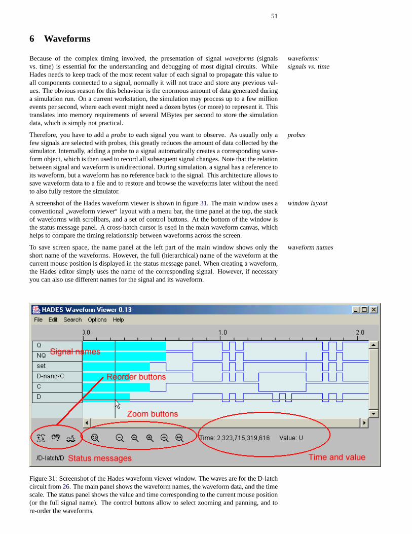
51
6 Waveforms
Because of the complex timing involved, the presentation of signalwaveforms(signals waveforms:signals vs. timevs. time) is essential for the understanding and debugging of most digital circuits. While
Hades needs to keep track of the most recent value of each signal to propagate this value toall components connected to a signal, normally it will not trace and store any previous val-ues. The obvious reason for this behaviour is the enormous amount of data generated duringa simulation run. On a current workstation, the simulation may process up to a few millionevents per second, where each event might need a dozen bytes (or more) to represent it. Thistranslates into memory requirements of several MBytes per second to store the simulationdata, which is simply not practical.
Therefore, you have to add aprobe to each signal you want to observe. As usually only aprobesfew signals are selected with probes, this greatly reduces the amount of data collected by thesimulator. Internally, adding a probe to a signal automatically creates a corresponding wave-form object, which is then used to record all subsequent signal changes. Note that the relationbetween signal and waveform is unidirectional. During simulation, a signal has a reference toits waveform, but a waveform has no reference back to the signal. This architecture allows tosave waveform data to a file and to restore and browse the waveforms later without the needto also fully restore the simulator.
A screenshot of the Hades waveform viewer is shown in figure31. The main window uses a window layoutconventional
”waveform viewer“ layout with a menu bar, the time panel at the top, the stack
of waveforms with scrollbars, and a set of control buttons. At the bottom of the window isthe status message panel. A cross-hatch cursor is used in the main waveform canvas, whichhelps to compare the timing relationship between waveforms across the screen.
To save screen space, the name panel at the left part of the main window shows only thewaveform namesshort name of the waveforms. However, the full (hierarchical) name of the waveform at thecurrent mouse position is displayed in the status message panel. When creating a waveform,the Hades editor simply uses the name of the corresponding signal. However, if necessaryyou can also use different names for the signal and its waveform.
Figure 31: Screenshot of the Hades waveform viewer window. The waves are for the D-latchcircuit from26. The main panel shows the waveform names, the waveform data, and the timescale. The status panel shows the value and time corresponding to the current mouse position(or the full signal name). The control buttons allow to select zooming and panning, and tore-order the waveforms.
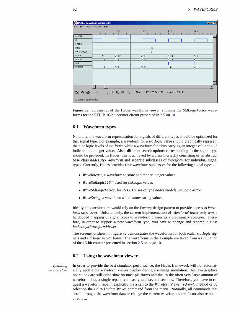
52 6 WAVEFORMS
Figure 32: Screenshot of the Hades waveform viewer, showing theStdLogicVectorwave-forms for the RTLIB 16-bit counter circuit presented in2.5on10.
6.1 Waveform types
Naturally, the waveform represenation for signals of different types should be optimized forthat signal type. For example, a waveform for astd logic value should graphically representthe nine logic levels ofstd logic, while a waveform for a bus carrying an integer value shouldindicate this integer value. Also, different search options corresponding to the signal typeshould be provided. In Hades, this is achieved by a class hierarchy consisting of an abstractbase classhades.styx.Waveformand separate subclasses ofWaveformfor individual signaltypes. Currently, Hades provides four waveform subclasses for the following signal types:
• WaveInteger, a waveform to store and render integer values
• WaveStdLogic1164, used forstd logic values
• WaveStdLogicVector, for RTLIBbuses of typehades.models.StdLogicVector.
• WaveString, a waveform which stores string values.
Ideally, this architecture would rely on theFactorydesign pattern to provide access toWave-form subclasses. Unfortunately, the current implementation ofWaveformVieweronly uses ahardcoded mapping of signal types to waveform classes as a preliminary solution. There-fore, in order to support a new waveform type, you have to change and recompile classhades.styx.WaveformViewer.
The screenshot shown in figure32 demonstrates the waveforms for both scalarstd logic sig-nals andstd logic vectorbuses. The waveforms in the example are taken from a simulationof the 16-bit counter presented in section2.5on page10.
6.2 Using the waveform viewer
In order to provide the best simulator performance, the Hades framework will not automat-repaintingmay be slow ically update the waveform viewer display during a running simulation. As Java graphics
operations are still quite slow on most platforms and due to the often very large amount ofwaveform data, a single repaint can easily take several seconds. Therefore, you have to re-quest a waveform repaint explicitly via a call to theWaveformViewer.redraw()method or byselection theEdit. Update Wavescommand from the menu. Naturally, all commands thatscroll throught the waveform data or change the current waveform zoom factor also result ina redraw.
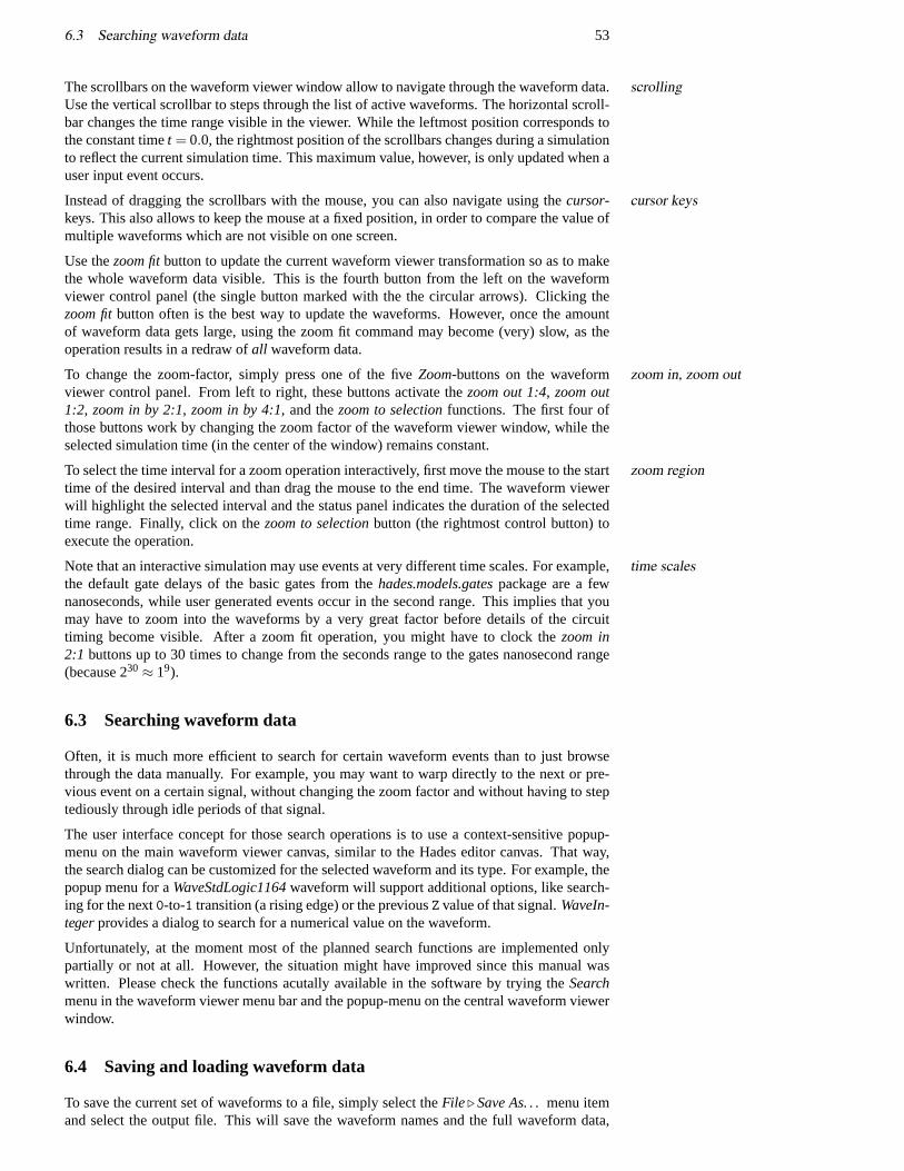
6.3 Searching waveform data 53
The scrollbars on the waveform viewer window allow to navigate through the waveform data.scrollingUse the vertical scrollbar to steps through the list of active waveforms. The horizontal scroll-bar changes the time range visible in the viewer. While the leftmost position corresponds tothe constant timet = 0.0, the rightmost position of the scrollbars changes during a simulationto reflect the current simulation time. This maximum value, however, is only updated when auser input event occurs.
Instead of dragging the scrollbars with the mouse, you can also navigate using thecursor- cursor keyskeys. This also allows to keep the mouse at a fixed position, in order to compare the value ofmultiple waveforms which are not visible on one screen.
Use thezoom fitbutton to update the current waveform viewer transformation so as to makethe whole waveform data visible. This is the fourth button from the left on the waveformviewer control panel (the single button marked with the the circular arrows). Clicking thezoom fitbutton often is the best way to update the waveforms. However, once the amountof waveform data gets large, using the zoom fit command may become (very) slow, as theoperation results in a redraw ofall waveform data.
To change the zoom-factor, simply press one of the fiveZoom-buttons on the waveform zoom in, zoom outviewer control panel. From left to right, these buttons activate thezoom out 1:4, zoom out1:2, zoom in by 2:1, zoom in by 4:1, and thezoom to selectionfunctions. The first four ofthose buttons work by changing the zoom factor of the waveform viewer window, while theselected simulation time (in the center of the window) remains constant.
To select the time interval for a zoom operation interactively, first move the mouse to the startzoom regiontime of the desired interval and than drag the mouse to the end time. The waveform viewerwill highlight the selected interval and the status panel indicates the duration of the selectedtime range. Finally, click on thezoom to selectionbutton (the rightmost control button) toexecute the operation.
Note that an interactive simulation may use events at very different time scales. For example,time scalesthe default gate delays of the basic gates from thehades.models.gatespackage are a fewnanoseconds, while user generated events occur in the second range. This implies that youmay have to zoom into the waveforms by a very great factor before details of the circuittiming become visible. After a zoom fit operation, you might have to clock thezoom in2:1 buttons up to 30 times to change from the seconds range to the gates nanosecond range(because 230≈ 19).
6.3 Searching waveform data
Often, it is much more efficient to search for certain waveform events than to just browsethrough the data manually. For example, you may want to warp directly to the next or pre-vious event on a certain signal, without changing the zoom factor and without having to steptediously through idle periods of that signal.
The user interface concept for those search operations is to use a context-sensitive popup-menu on the main waveform viewer canvas, similar to the Hades editor canvas. That way,the search dialog can be customized for the selected waveform and its type. For example, thepopup menu for aWaveStdLogic1164waveform will support additional options, like search-ing for the next0-to-1 transition (a rising edge) or the previousZ value of that signal.WaveIn-tegerprovides a dialog to search for a numerical value on the waveform.
Unfortunately, at the moment most of the planned search functions are implemented onlypartially or not at all. However, the situation might have improved since this manual waswritten. Please check the functions acutally available in the software by trying theSearchmenu in the waveform viewer menu bar and the popup-menu on the central waveform viewerwindow.
6.4 Saving and loading waveform data
To save the current set of waveforms to a file, simply select theFile . Save As. . .menu itemand select the output file. This will save the waveform names and the full waveform data,
54 6 WAVEFORMS
but no references to the Hades editor or simulator. This means that the waveform data canbe restored for displaying, but not for simulation. SelectFile . Load. . . to load a previouslysaved set of waveform data.
6.5 Scripting
When using waveforms to debug or demonstrate a circuit, it is often necessary to select thesame set of probes for several runs of the simulator, which can become very cumbersome viathe GUI. Instead, you may want to automate this task by scripting. For details about scriptingthe Hades editor and simulator with Java or Jython see section8 on page65. The followingcode example shows the principle of selecting probes via a Jython script:
# Jython/Python script for waveform initialization...
# create an editor and load a design into the editor#from hades.gui import Editoreditor = Editor()editor.doOpenDesign( "designname.hds", 1 )
# create probes for selected signals#design = editor.getDesign()signalNames = [ ’D’, ’C’, ’i1.y’, ’i0.y’, ’Q’, ’NQ’ ]for i in range( len( signalNames )):
signal = design.getSignal( signalNames[i] )if (signal != None):
editor.addProbeToSignal( signalNames[i] )
# create and show the waveform viewer#editor.doShowWaves()waveformViewer = editor.getWaveformViewer()waveformViewer.setBounds( 450, 50, 500, 400 )...
# update waveform viewer display#waveformViewer.updateTrafo()waveformViewer.getWaveCanvas().zoomFit()waveformViewer.redraw()...
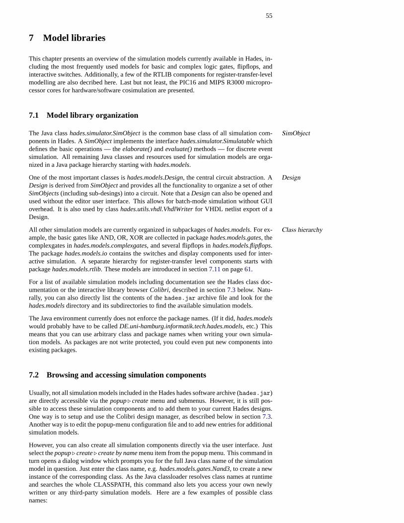
55
7 Model libraries
This chapter presents an overview of the simulation models currently available in Hades, in-cluding the most frequently used models for basic and complex logic gates, flipflops, andinteractive switches. Additionally, a few of the RTLIB components for register-transfer-levelmodelling are also decribed here. Last but not least, the PIC16 and MIPS R3000 micropro-cessor cores for hardware/software cosimulation are presented.
7.1 Model library organization
The Java classhades.simulator.SimObjectis the common base class of all simulation com-SimObjectponents in Hades. ASimObjectimplements the interfacehades.simulator.Simulatablewhichdefines the basic operations — theelaborate()andevaluate()methods — for discrete eventsimulation. All remaining Java classes and resources used for simulation models are orga-nized in a Java package hierarchy starting withhades.models.
One of the most important classes ishades.models.Design, the central circuit abstraction. A DesignDesignis derived fromSimObjectand provides all the functionality to organize a set of otherSimObjects(including sub-desings) into a circuit. Note that aDesigncan also be opened andused without the editor user interface. This allows for batch-mode simulation without GUIoverhead. It is also used by classhades.utils.vhdl.VhdlWriterfor VHDL netlist export of aDesign.
All other simulation models are currently organized in subpackages ofhades.models. For ex- Class hierarchyample, the basic gates like AND, OR, XOR are collected in packagehades.models.gates, thecomplexgates inhades.models.complexgates, and several flipflops inhades.models.flipflops.The packagehades.models.iocontains the switches and display components used for inter-active simulation. A separate hierarchy for register-transfer level components starts withpackagehades.models.rtlib. These models are introduced in section7.11on page61.
For a list of available simulation models including documentation see the Hades class doc-umentation or the interactive library browserColibri, described in section7.3 below. Natu-rally, you can also directly list the contents of thehades.jar archive file and look for thehades.modelsdirectory and its subdirectories to find the available simulation models.
The Java environment currently does not enforce the package names. (If it did,hades.modelswould probably have to be calledDE.uni-hamburg.informatik.tech.hades.models, etc.) Thismeans that you can use arbitrary class and package names when writing your own simula-tion models. As packages are not write protected, you could even put new components intoexisting packages.
7.2 Browsing and accessing simulation components
Usually, not all simulation models included in the Hades hades software archive (hades.jar)are directly accessible via thepopup. createmenu and submenus. However, it is still pos-sible to access these simulation components and to add them to your current Hades designs.One way is to setup and use the Colibri design manager, as described below in section7.3.Another way is to edit the popup-menu configuration file and to add new entries for additionalsimulation models.
However, you can also create all simulation components directly via the user interface. Justselect thepopup. create. create by namemenu item from the popup menu. This command inturn opens a dialog window which prompts you for the full Java class name of the simulationmodel in question. Just enter the class name, e.g.hades.models.gates.Nand3, to create a newinstance of the corresponding class. As the Java classloader resolves class names at runtimeand searches the whole CLASSPATH, this command also lets you access your own newlywritten or any third-party simulation models. Here are a few examples of possible classnames:
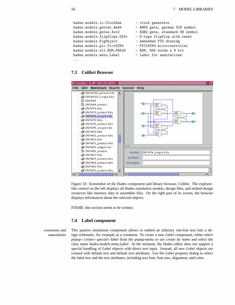
56 7 MODEL LIBRARIES
hades.models.io.ClockGen - clock generatorhades.models.gatter.And4 - AND4 gate, german DIN symbolhades.models.gates.Xor2 - XOR2 gate, standard US symbolhades.models.flipflops.Dffr - D-type flipflop with resethades.models.FigObject - embedded FIG drawinghades.models.pic.Pic16C84 - PIC16C84 microcontrollerhades.models.rtl.ROM_64Kx8 - ROM, 64K words a 8 bithades.models.meta.Label - label for annotations...
7.3 Colibri Browser
Figure 33: Screenshot of the Hades component and library browser, Colibri. The explorer-like control on the left displays all Hades simulation models, design files, and related designresources like memory data or assembler files. On the right part of its screen, the browserdisplays information about the selected objects.
FIXME: this section needs to be written.
7.4 Label component
This passive simulation component allows to embed an arbitrary one-line text into a de-comments andannotations sign schematic, for example as a comment. To create a newLabelcomponent, either select
popup. create. special. label from the popup-menu or usecreate by nameand select theclass namehades.models.meta.Label. At the moment, the Hades editor does not support aspecial handling ofLabel objects with direct text input. Instead, all newLabel objects arecreated with default text and default text attributes. Use theLabelproperty dialog to selectthe label text and the text attributes, including text font, font size, alignment, and color.
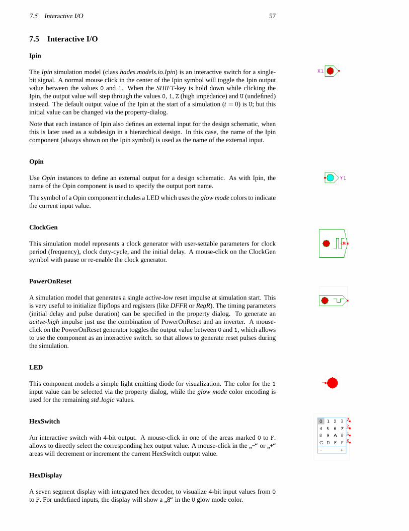
7.5 Interactive I/O 57
7.5 Interactive I/O
Ipin
The Ipin simulation model (classhades.models.io.Ipin) is an interactive switch for a single-bit signal. A normal mouse click in the center of the Ipin symbol will toggle the Ipin outputvalue between the values0 and1. When theSHIFT-key is hold down while clicking theIpin, the output value will step through the values0, 1, Z (high impedance) andU (undefined)instead. The default output value of the Ipin at the start of a simulation (t = 0) is U; but thisinitial value can be changed via the property-dialog.
Note that each instance of Ipin also defines an external input for the design schematic, whenthis is later used as a subdesign in a hierarchical design. In this case, the name of the Ipincomponent (always shown on the Ipin symbol) is used as the name of the external input.
Opin
UseOpin instances to define an external output for a design schematic. As with Ipin, thename of the Opin component is used to specify the output port name.
The symbol of a Opin component includes a LED which uses theglow modecolors to indicatethe current input value.
ClockGen
This simulation model represents a clock generator with user-settable parameters for clockperiod (frequency), clock duty-cycle, and the initial delay. A mouse-click on the ClockGensymbol with pause or re-enable the clock generator.
PowerOnReset
A simulation model that generates a singleactive-lowreset impulse at simulation start. Thisis very useful to initialize flipflops and registers (likeDFFRor RegR). The timing parameters(initial delay and pulse duration) can be specified in the property dialog. To generate anacitve-highimpulse just use the combination of PowerOnReset and an inverter. A mouse-click on the PowerOnReset generator toggles the output value between0 and1, which allowsto use the component as an interactive switch. so that allows to generate reset pulses duringthe simulation.
LED
This component models a simple light emitting diode for visualization. The color for the1input value can be selected via the property dialog, while theglow modecolor encoding isused for the remainingstd logic values.
HexSwitch
An interactive switch with 4-bit output. A mouse-click in one of the areas marked0 to F.allows to directly select the corresponding hex output value. A mouse-click in the
”-“ or
”+“
areas will decrement or increment the current HexSwitch output value.
HexDisplay
A seven segment display with integrated hex decoder, to visualize 4-bit input values from0to F. For undefined inputs, the display will show a
”8“ in theU glow mode color.
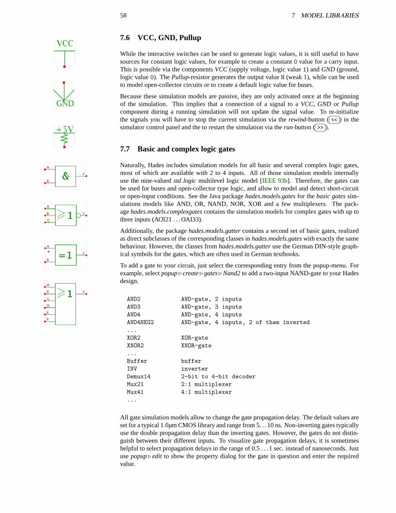
58 7 MODEL LIBRARIES
7.6 VCC, GND, Pullup
While the interactive switches can be used to generate logic values, it is still useful to havesources for constant logic values, for example to create a constant0 value for a carry input.This is possible via the componentsVCC (supply voltage, logic value1) andGND (ground,logic value0). ThePullup-resistor generates the output valueH (weak 1), while can be usedto model open-collector circuits or to create a default logic value for buses.
Because these simulation models are passive, they are only activated once at the beginningof the simulation. This implies that a connection of a signal to aVCC, GND or Pullupcomponent during a running simulation will not update the signal value. To re-initializethe signals you will have to stop the current simulation via therewind-button (
�� ��<< ) in thesimulator control panel and the to restart the simulation via therun-button (
�� ��>> ).
7.7 Basic and complex logic gates
Naturally, Hades includes simulation models for all basic and several complex logic gates,most of which are available with 2 to 4 inputs. All of those simulation models internallyuse the nine-valuedstd logic multilevel logic model [IEEE 93b]. Therefore, the gates canbe used for buses and open-collector type logic, and allow to model and detect short-circuitor open-input conditions. See the Java packagehades.models.gatesfor thebasic gatessim-ulations models like AND, OR, NAND, NOR, XOR and a few multiplexers. The pack-agehades.models.complexgatescontains the simulation models for complex gates with up tothree inputs (AOI21 . . . OAI33).
Additionally, the packagehades.models.gattercontains a second set of basic gates, realizedas direct subclasses of the corresponding classes inhades.models.gateswith exactly the samebehaviour. However, the classes fromhades.models.gatteruse the German DIN-style graph-ical symbols for the gates, which are often used in German textbooks.
To add a gate to your circuit, just select the corresponding entry from the popup-menu. Forexample, selectpopup. create. gates. Nand2to add a two-input NAND-gate to your Hadesdesign.
AND2 AND-gate, 2 inputsAND3 AND-gate, 3 inputsAND4 AND-gate, 4 inputsAND4NEG2 AND-gate, 4 inputs, 2 of them inverted...XOR2 XOR-gateXNOR2 XNOR-gate...Buffer bufferINV inverterDemux14 2-bit to 4-bit decoderMux21 2:1 multiplexerMux41 4:1 multiplexer...
All gate simulation models allow to change the gate propagation delay. The default values areset for a typical 1.0µm CMOS library and range from 5. . . 10 ns. Non-inverting gates typicallyuse the double propagation delay than the inverting gates. However, the gates do not distin-guish between their different inputs. To visualize gate propagation delays, it is sometimeshelpful to select propagation delays in the range of 0.5 . . . 1 sec. instead of nanoseconds. Justusepopup. edit to show the property dialog for the gate in question and enter the requiredvalue.
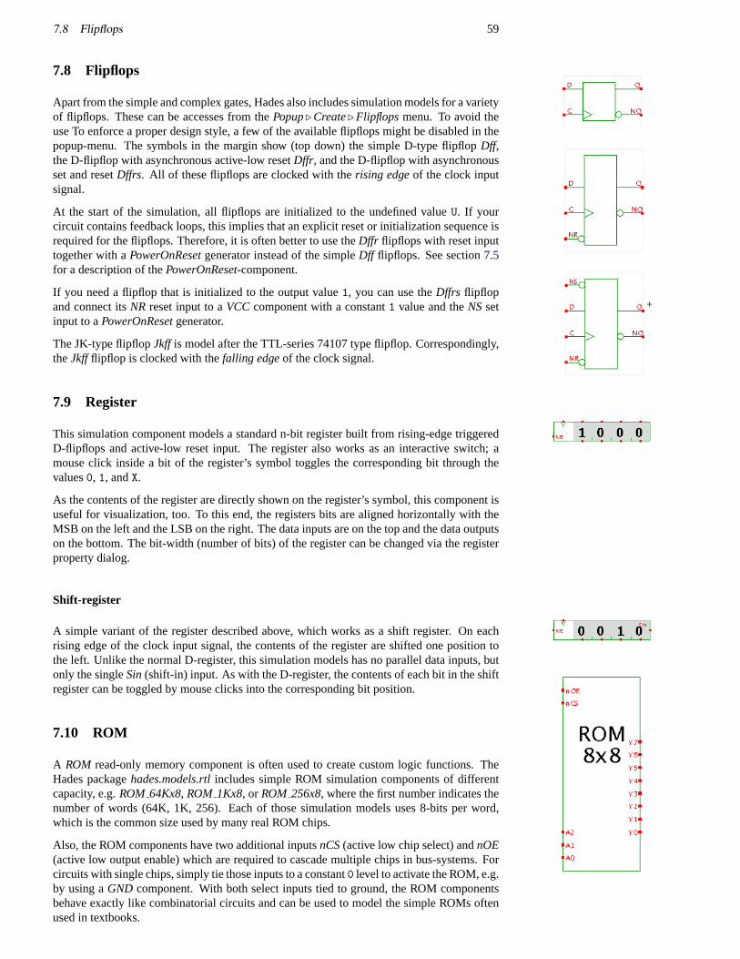
7.8 Flipflops 59
7.8 Flipflops
Apart from the simple and complex gates, Hades also includes simulation models for a varietyof flipflops. These can be accesses from thePopup. Create. Flipflopsmenu. To avoid theuse To enforce a proper design style, a few of the available flipflops might be disabled in thepopup-menu. The symbols in the margin show (top down) the simple D-type flipflopDff,the D-flipflop with asynchronous active-low resetDffr, and the D-flipflop with asynchronousset and resetDffrs. All of these flipflops are clocked with therising edgeof the clock inputsignal.
At the start of the simulation, all flipflops are initialized to the undefined valueU. If yourcircuit contains feedback loops, this implies that an explicit reset or initialization sequence isrequired for the flipflops. Therefore, it is often better to use theDffr flipflops with reset inputtogether with aPowerOnResetgenerator instead of the simpleDff flipflops. See section7.5for a description of thePowerOnReset-component.
If you need a flipflop that is initialized to the output value1, you can use theDffrs flipflopand connect itsNR reset input to aVCCcomponent with a constant1 value and theNSsetinput to aPowerOnResetgenerator.
The JK-type flipflopJkff is model after the TTL-series 74107 type flipflop. Correspondingly,theJkffflipflop is clocked with thefalling edgeof the clock signal.
7.9 Register
This simulation component models a standard n-bit register built from rising-edge triggeredD-flipflops and active-low reset input. The register also works as an interactive switch; amouse click inside a bit of the register’s symbol toggles the corresponding bit through thevalues0, 1, andX.
As the contents of the register are directly shown on the register’s symbol, this component isuseful for visualization, too. To this end, the registers bits are aligned horizontally with theMSB on the left and the LSB on the right. The data inputs are on the top and the data outputson the bottom. The bit-width (number of bits) of the register can be changed via the registerproperty dialog.
Shift-register
A simple variant of the register described above, which works as a shift register. On eachrising edge of the clock input signal, the contents of the register are shifted one position tothe left. Unlike the normal D-register, this simulation models has no parallel data inputs, butonly the singleSin(shift-in) input. As with the D-register, the contents of each bit in the shiftregister can be toggled by mouse clicks into the corresponding bit position.
7.10 ROM
A ROM read-only memory component is often used to create custom logic functions. TheHades packagehades.models.rtlincludes simple ROM simulation components of differentcapacity, e.g.ROM 64Kx8, ROM 1Kx8, or ROM 256x8, where the first number indicates thenumber of words (64K, 1K, 256). Each of those simulation models uses 8-bits per word,which is the common size used by many real ROM chips.
Also, the ROM components have two additional inputsnCS(active low chip select) andnOE(active low output enable) which are required to cascade multiple chips in bus-systems. Forcircuits with single chips, simply tie those inputs to a constant0 level to activate the ROM, e.g.by using aGND component. With both select inputs tied to ground, the ROM componentsbehave exactly like combinatorial circuits and can be used to model the simple ROMs oftenused in textbooks.
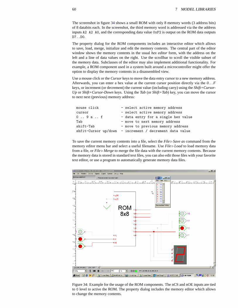
60 7 MODEL LIBRARIES
The screenshot in figure34 shows a small ROM with only 8 memory words (3 address bits)of 8 databits each. In the screenshot, the third memory word is addressed via the the addressinputsA2 A2 A0, and the corresponding data value0xF2 is output on the ROM data outputsD7..D0.
The property dialog for the ROM components includes an interactive editor which allowsto save, load, merge, initialize and edit the memory contents. The central part of the editorwindow shows the memory contents in the usualhex editorform, with the address on theleft and a line of data values on the right. Use the scrollbar to scroll the visible subset ofthe memory data. Subclasses of the editor may also implement additional functionality. Forexample, a ROM component used in a system built around a microcontroller might offer theoption to display the memory contents in a disassembled view.
Use a mouse click or theCursorkeys to move the data entry cursor to a new memory address.Afterwards, you can enter a hex value at the current cursor position directly via the0. . .Fkeys, or increment (or decrement) the current value (including carry) using theShift+Cursor-Up or Shift+Cursor-Downkeys. Using theTab (or Shift+Tab) key, you can move the cursorto next next (previous) memory address:
mouse click - select active memory addresscursor - select active memory address0 .. 9 a .. f - data entry for a single hex valueTab - move to next memory addressshift-Tab - move to previous memory addressshfit-Cursor up/down - increment / decrement data value
To save the current memory contents into a file, select theFile . Save ascommand from thememory editor menu bar and select a useful filename. UseFile . Load to load memory datafrom a file, orFile . Mergeto merge the file data with the current memory contents. Becausethe memory data is stored in standard text files, you can also edit those files with your favoritetext editor, or use a program to automatically generate memory data files.
Figure 34: Example for the usage of the ROM components. The nCS and nOE inputs are tiedto 0 level to active the ROM. The property dialog includes the memory editor which allowsto change the memory contents.
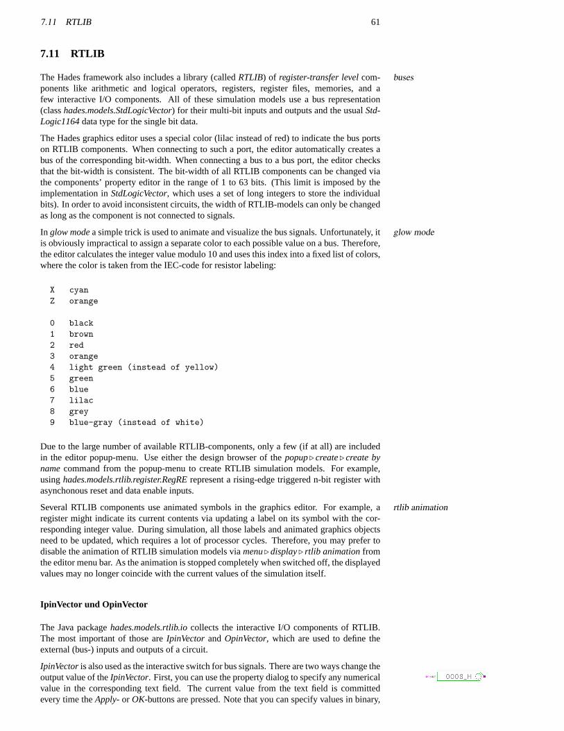
7.11 RTLIB 61
7.11 RTLIB
The Hades framework also includes a library (calledRTLIB) of register-transfer levelcom- busesponents like arithmetic and logical operators, registers, register files, memories, and afew interactive I/O components. All of these simulation models use a bus representation(classhades.models.StdLogicVector) for their multi-bit inputs and outputs and the usualStd-Logic1164data type for the single bit data.
The Hades graphics editor uses a special color (lilac instead of red) to indicate the bus portson RTLIB components. When connecting to such a port, the editor automatically creates abus of the corresponding bit-width. When connecting a bus to a bus port, the editor checksthat the bit-width is consistent. The bit-width of all RTLIB components can be changed viathe components’ property editor in the range of 1 to 63 bits. (This limit is imposed by theimplementation inStdLogicVector, which uses a set of long integers to store the individualbits). In order to avoid inconsistent circuits, the width of RTLIB-models can only be changedas long as the component is not connected to signals.
In glow modea simple trick is used to animate and visualize the bus signals. Unfortunately, itglow modeis obviously impractical to assign a separate color to each possible value on a bus. Therefore,the editor calculates the integer value modulo 10 and uses this index into a fixed list of colors,where the color is taken from the IEC-code for resistor labeling:
X cyanZ orange
0 black1 brown2 red3 orange4 light green (instead of yellow)5 green6 blue7 lilac8 grey9 blue-gray (instead of white)
Due to the large number of available RTLIB-components, only a few (if at all) are includedin the editor popup-menu. Use either the design browser of thepopup. create. create bynamecommand from the popup-menu to create RTLIB simulation models. For example,usinghades.models.rtlib.register.RegRErepresent a rising-edge triggered n-bit register withasynchonous reset and data enable inputs.
Several RTLIB components use animated symbols in the graphics editor. For example, artlib animationregister might indicate its current contents via updating a label on its symbol with the cor-responding integer value. During simulation, all those labels and animated graphics objectsneed to be updated, which requires a lot of processor cycles. Therefore, you may prefer todisable the animation of RTLIB simulation models viamenu. display. rtlib animationfromthe editor menu bar. As the animation is stopped completely when switched off, the displayedvalues may no longer coincide with the current values of the simulation itself.
IpinVector und OpinVector
The Java packagehades.models.rtlib.iocollects the interactive I/O components of RTLIB.The most important of those areIpinVectorandOpinVector, which are used to define theexternal (bus-) inputs and outputs of a circuit.
IpinVectoris also used as the interactive switch for bus signals. There are two ways change theoutput value of theIpinVector. First, you can use the property dialog to specify any numericalvalue in the corresponding text field. The current value from the text field is committedevery time theApply- or OK-buttons are pressed. Note that you can specify values in binary,
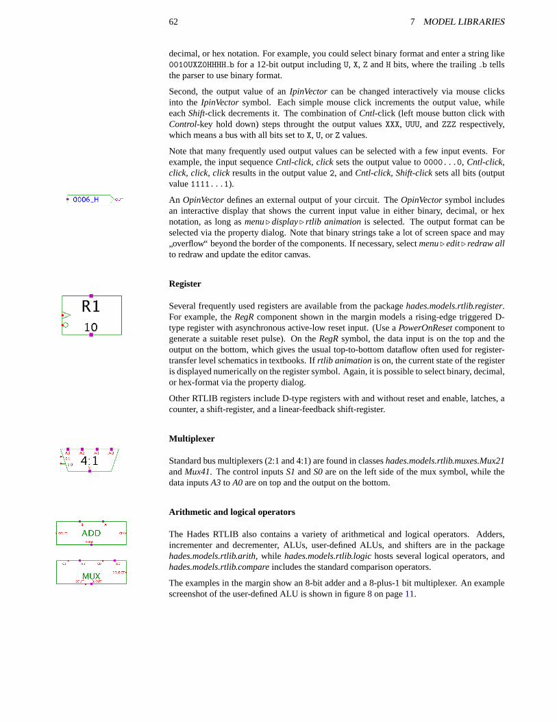
62 7 MODEL LIBRARIES
decimal, or hex notation. For example, you could select binary format and enter a string like0010UXZ0HHHH b for a 12-bit output includingU, X, Z andH bits, where the trailingb tellsthe parser to use binary format.
Second, the output value of anIpinVector can be changed interactively via mouse clicksinto the IpinVector symbol. Each simple mouse click increments the output value, whileeachShift-click decrements it. The combination ofCntl-click (left mouse button click withControl-key hold down) steps throught the output valuesXXX, UUU, andZZZ respectively,which means a bus with all bits set toX, U, or Z values.
Note that many frequently used output values can be selected with a few input events. Forexample, the input sequenceCntl-click, clicksets the output value to0000...0, Cntl-click,click, click, clickresults in the output value2, andCntl-click, Shift-clicksets all bits (outputvalue1111...1).
An OpinVectordefines an external output of your circuit. TheOpinVectorsymbol includesan interactive display that shows the current input value in either binary, decimal, or hexnotation, as long asmenu. display. rtlib animation is selected. The output format can beselected via the property dialog. Note that binary strings take a lot of screen space and may
”overflow“ beyond the border of the components. If necessary, selectmenu. edit. redraw all
to redraw and update the editor canvas.
Register
Several frequently used registers are available from the packagehades.models.rtlib.register.For example, theRegRcomponent shown in the margin models a rising-edge triggered D-type register with asynchronous active-low reset input. (Use aPowerOnResetcomponent togenerate a suitable reset pulse). On theRegRsymbol, the data input is on the top and theoutput on the bottom, which gives the usual top-to-bottom dataflow often used for register-transfer level schematics in textbooks. Ifrtlib animationis on, the current state of the registeris displayed numerically on the register symbol. Again, it is possible to select binary, decimal,or hex-format via the property dialog.
Other RTLIB registers include D-type registers with and without reset and enable, latches, acounter, a shift-register, and a linear-feedback shift-register.
Multiplexer
Standard bus multiplexers (2:1 and 4:1) are found in classeshades.models.rtlib.muxes.Mux21andMux41. The control inputsS1andS0are on the left side of the mux symbol, while thedata inputsA3 to A0are on top and the output on the bottom.
Arithmetic and logical operators
The Hades RTLIB also contains a variety of arithmetical and logical operators. Adders,incrementer and decrementer, ALUs, user-defined ALUs, and shifters are in the packagehades.models.rtlib.arith, while hades.models.rtlib.logichosts several logical operators, andhades.models.rtlib.compareincludes the standard comparison operators.
The examples in the margin show an 8-bit adder and a 8-plus-1 bit multiplexer. An examplescreenshot of the user-defined ALU is shown in figure8 on page11.
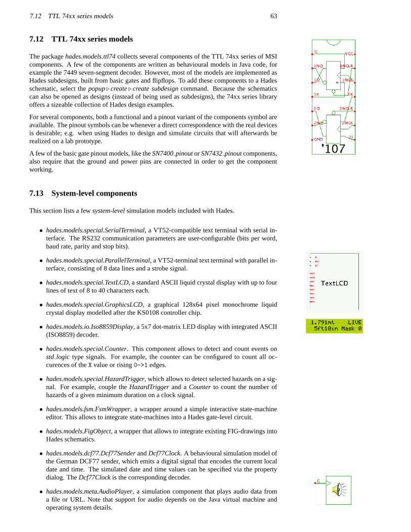
7.12 TTL 74xx series models 63
7.12 TTL 74xx series models
The packagehades.models.ttl74collects several components of the TTL 74xx series of MSIcomponents. A few of the components are written as behavioural models in Java code, forexample the 7449 seven-segment decoder. However, most of the models are implemented asHades subdesigns, built from basic gates and flipflops. To add these components to a Hadesschematic, select thepopup. create. create subdesigncommand. Because the schematicscan also be opened as designs (instead of being used as subdesigns), the 74xx series libraryoffers a sizeable collection of Hades design examples.
For several components, both a functional and a pinout variant of the components symbol areavailable. The pinout symbols can be whenever a direct correspondence with the real devicesis desirable; e.g. when using Hades to design and simulate circuits that will afterwards berealized on a lab prototype.
A few of the basic gate pinout models, like theSN7400pinoutorSN7432pinoutcomponents,also require that the ground and power pins are connected in order to get the componentworking.
7.13 System-level components
This section lists a fewsystem-levelsimulation models included with Hades.
• hades.models.special.SerialTerminal, a VT52-compatible text terminal with serial in-terface. The RS232 communication parameters are user-configurable (bits per word,baud rate, parity and stop bits).
• hades.models.special.ParallelTerminal, a VT52-terminal text terminal with parallel in-terface, consisting of 8 data lines and a strobe signal.
• hades.models.special.TextLCD, a standard ASCII liquid crystal display with up to fourlines of text of 8 to 40 characters each.
• hades.models.special.GraphicsLCD, a graphical 128x64 pixel monochrome liquidcrystal display modelled after the KS0108 controller chip.
• hades.models.io.Iso8859Display, a 5x7 dot-matrix LED display with integrated ASCII(ISO8859) decoder.
• hades.models.special.Counter. This component allows to detect and count events onstd logic type signals. For example, the counter can be configured to count all oc-curences of theX value or rising0->1 edges.
• hades.models.special.HazardTrigger, which allows to detect selected hazards on a sig-nal. For example, couple theHazardTriggerand aCounterto count the number ofhazards of a given minimum duration on a clock signal.
• hades.models.fsm.FsmWrapper, a wrapper around a simple interactive state-machineeditor. This allows to integrate state-machines into a Hades gate-level circuit.
• hades.models.FigObject, a wrapper that allows to integrate existing FIG-drawings intoHades schematics.
• hades.models.dcf77.Dcf77SenderandDcf77Clock. A behavioural simulation model ofthe German DCF77 sender, which emits a digital signal that encodes the current localdate and time. The simulated date and time values can be specified via the propertydialog. TheDcf77Clockis the corresponding decoder.
• hades.models.meta.AudioPlayer, a simulation component that plays audio data froma file or URL. Note that support for audio depends on the Java virtual machine andoperating system details.
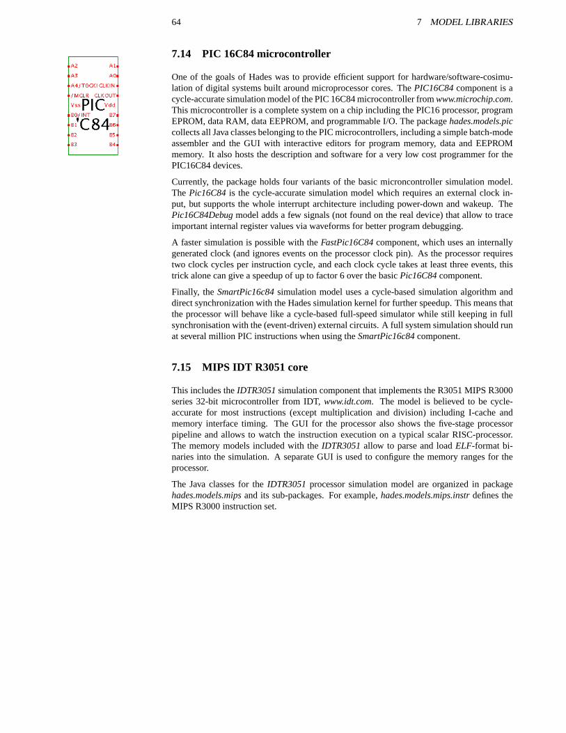
64 7 MODEL LIBRARIES
7.14 PIC 16C84 microcontroller
One of the goals of Hades was to provide efficient support for hardware/software-cosimu-lation of digital systems built around microprocessor cores. ThePIC16C84component is acycle-accurate simulation model of the PIC 16C84 microcontroller fromwww.microchip.com.This microcontroller is a complete system on a chip including the PIC16 processor, programEPROM, data RAM, data EEPROM, and programmable I/O. The packagehades.models.piccollects all Java classes belonging to the PIC microcontrollers, including a simple batch-modeassembler and the GUI with interactive editors for program memory, data and EEPROMmemory. It also hosts the description and software for a very low cost programmer for thePIC16C84 devices.
Currently, the package holds four variants of the basic microncontroller simulation model.The Pic16C84is the cycle-accurate simulation model which requires an external clock in-put, but supports the whole interrupt architecture including power-down and wakeup. ThePic16C84Debugmodel adds a few signals (not found on the real device) that allow to traceimportant internal register values via waveforms for better program debugging.
A faster simulation is possible with theFastPic16C84component, which uses an internallygenerated clock (and ignores events on the processor clock pin). As the processor requirestwo clock cycles per instruction cycle, and each clock cycle takes at least three events, thistrick alone can give a speedup of up to factor 6 over the basicPic16C84component.
Finally, theSmartPic16c84simulation model uses a cycle-based simulation algorithm anddirect synchronization with the Hades simulation kernel for further speedup. This means thatthe processor will behave like a cycle-based full-speed simulator while still keeping in fullsynchronisation with the (event-driven) external circuits. A full system simulation should runat several million PIC instructions when using theSmartPic16c84component.
7.15 MIPS IDT R3051 core
This includes theIDTR3051simulation component that implements the R3051 MIPS R3000series 32-bit microcontroller from IDT,www.idt.com. The model is believed to be cycle-accurate for most instructions (except multiplication and division) including I-cache andmemory interface timing. The GUI for the processor also shows the five-stage processorpipeline and allows to watch the instruction execution on a typical scalar RISC-processor.The memory models included with theIDTR3051allow to parse and loadELF-format bi-naries into the simulation. A separate GUI is used to configure the memory ranges for theprocessor.
The Java classes for theIDTR3051processor simulation model are organized in packagehades.models.mipsand its sub-packages. For example,hades.models.mips.instrdefines theMIPS R3000 instruction set.
65
8 Scripting and Stimuli
While the interactive simulation mode with its direct control and immediate feedback via theautomationuser interface is one of the advantages of the Hades framework, the simulation and debuggingor more complex circuits can profit greatly from scripting. Also, scripting allows to executemethods which are not accessible directly via the user interface. For example, the setup andselection of probes to watch important signals with waveforms is a tiresome operation whichcan easily be automated.
Of coure, every scripting language with a Java binding can be used to control and automatelanguagesthe Hades framework, including JavaScript, EcmaScript, Tcl, or the BeanShell. However, thefollowing sections will concentrate on just two languages, namely Java and Jython. First, afew code-examples explain how to control the Hades simulator and editor from user-suppliedJava classes. Second, a Jython-script is presented to show the excellent integration of Jythoncode into the Java runtime environment.
8.1 Java-written scripts
The easiest way to control the Hades framework including editor and simulator is to write ad-pure-Javaditional Java classes, one of which is then used as the main program. The obvious advantageof this technique is that only one source language is used and there is no need for additionalruntime support, except possibly for the Java virtual machine CLASSPATH setup. Also, theperformance of Java code should be better than that of interpreted scripting languages. On thedown side, Java code is compiled and only very few runtime environments allow to changeJava code on-the-fly.
The following code example illustrates the basic concepts of using Java to script the Hadessimulator and editor. The new class,RunHadesDemo, is used to setup and create a Hadeseditor and to run a simple simulation. The first code snippet presents the new class and itsmain()method. As usual, a fewimport statements indicate what classes are used and help toavoid typing the fully-qualified class names:
/* RunHadesDemo.java - run and control a Hades simulation** set CLASSPATH to include "hades.jar" and "RunHadesDemo.class",* then start with "java RunHadesDemo"*/import jfig.utils.SetupManager; // properties managementimport hades.gui.*; // Editor and GUI stuffimport hades.models.Design;import hades.models.Const1164; // std_logic constantsimport hades.models.io.Ipin; // switches
public class RunHadesDemo {public static void main( String argv[] ) {
...}
}
The following few lines of code are used to initialize the simulator and editor setup from theSetupManagerglobal, user, and local properties resource-files. Naturally, properties can also be set from theJava code itself:
public static void main( String argv[] ) {SetupManager.loadGlobalProperties( "hades/.hadesrc" );SetupManager.loadUserProperties( ".hadesrc" );SetupManager.loadLocalProperties( ".hadesrc" );
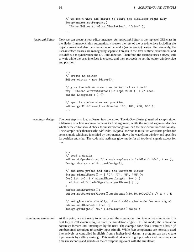
66 8 SCRIPTING AND STIMULI
// we don’t want the editor to start the simulator right awaySetupManager.setProperty("Hades.Editor.AutoStartSimulation", "false" );
...
Now we can create a new editor instance. Ashades.gui.Editoris the toplevel GUI class inhades.gui.Editorthe Hades framework, this automatically creates the rest of the user-interface including theobject canvas, and also the simulation kernel and a (so far empty) design. Unfortunately, theuser-interface classes are managed by separate Threads in the Java runtime environment andit is difficult to synchronize the GUI initialization. Therefore, the example uses asleep()callto wait while the user interface is created, and then proceeds to set the editor window sizeand position:
...// create an editorEditor editor = new Editor();
// give the editor some time to initialize itselftry { Thread.currentThread().sleep( 2000 ); } // msec.catch( Exception e ) {}
// specify window size and positioneditor.getEditFrame().setBounds( 100, 100, 700, 500 );...
The next step is to load aDesigninto the editor. ThedoOpenDesign()method accepts eitheropening a designa filename or a Java resource name as its first argument, while the second argument decideswhether the editor should check for unsaved changes or load the new circuit unconditionally.The example code then uses theaddProbeToSignal()method to initialize waveform probes forsome signals which are identified by their names, shows the waveform window and specifiesits position and size. The code also activates glow-mode for all top-level signals except forone:
...// load a designeditor.doOpenDesign( "/hades/examples/simple/dlatch.hds", true );Design design = editor.getDesign();
// add some probes and show the waveform viewerString signalNames[] = { "D", "C", "Q", "NQ" };for( int i=0; i < signalNames.length; i++ ) {editor.addProbeToSignal( signalNames[i] );
}editor.doShowWaves();editor.getWaveformViewer().setBounds(450,50,500,400); // x y w h
// set glow mode globally, then disable glow mode for one signaleditor.setGlowMode( true );design.getSignal( "NQ" ).setGlowMode( false );
At this point, we are ready to actually run the simulation. For interactive simulation it isrunning the simulationbest to just callrunForever() to start the simulation engine. In this mode, the simulationcontinues forever until interrupted by the user. The example code also illustrates a basic (ifcumbersome) technique to specify input stimuli. WhileIpin components are normally usedinteractively or controlled implicitly from a higher-level design, a program can also createinput events by callingassign(). This method takes a string input value and the simulationtime (in seconds) and schedules the corresponding event with the simulator:
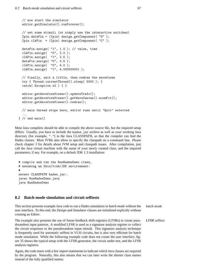
8.2 Batch-mode simulation and circuit selftests 67
// now start the simulatoreditor.getSimulator().runForever();
// set some stimuli (or simply use the interactive switches)Ipin dataPin = (Ipin) design.getComponent( "D" );Ipin clkPin = (Ipin) design.getComponent( "C" );
dataPin.assign( "1", 1.0 ); // value, timeclkPin.assign( "0", 2.0 );clkPin.assign( "1", 2.5 );dataPin.assign( "0", 3.5 );clkPin.assign( "0", 4.0 );clkPin.assign( "1", 4.000000001 );
// finally, wait a little, then redraw the waveformstry { Thread.currentThread().sleep( 5000 ); }catch( Exception e2 ) { }
editor.getWaveformViewer().updateTrafo();editor.getWaveformViewer().getWaveCanvas().zoomFit();editor.getWaveformViewer().redraw();
// main thread stops here, editor runs until "Quit" selected...
} // end main()
Most Java compilers should be able to compile the above source file, but the required setupdiffers. Usually, you have to include thehades.jar archive as well as your working Javadirectory (for example,".") in the Java CLASSPATH, so that the compiler can find theHades classes. Most JVMs also allow to specify the classpath on a command line. Pleasecheck chapter3 for details about JVM setup and classpath issues. After compilation, justcall the Java virtual machine with the name of your newly created class, and the requiredparameters, if any. For example, on a default JDK 1.3 installation:
# compile and run the RunHadesDemo class,# assuming an Unix/tcsh/JDK environment:#setenv CLASSPATH hades.jar:.javac RunHadesDemo.javajava RunHadesDemo
8.2 Batch-mode simulation and circuit selftests
This section presents example Java code to run a Hades simulation inbatch-modewithout the batch-modeuser interface. To this end, theDesignandSimulatorclasses are initialized explicitly withoutcreating anEditor.
The example also presents the use of linear-feedback shift-registers (LFSRs) to create pseu-LFSR selftestdorandom input patterns. A modified LFSR is used as a signature analysis register to collectthe circuit responses to the pseudorandom input stimuli. This signature analysis techniqueis frequently used for automatic selftest in VLSI circuits, but is also very efficient for batchmode simulation. While the following example code does not create the user interface, fig-ure35shows the typical setup with the LFSR-generator, the circuit under test, and the LFSRanalysis registers.
Again, the code starts with a fewimportstatements to indicate which Java classes are requiredby the program. Naturally, this also means that we can later write the shorter class namesinstead of the fully qualified names:
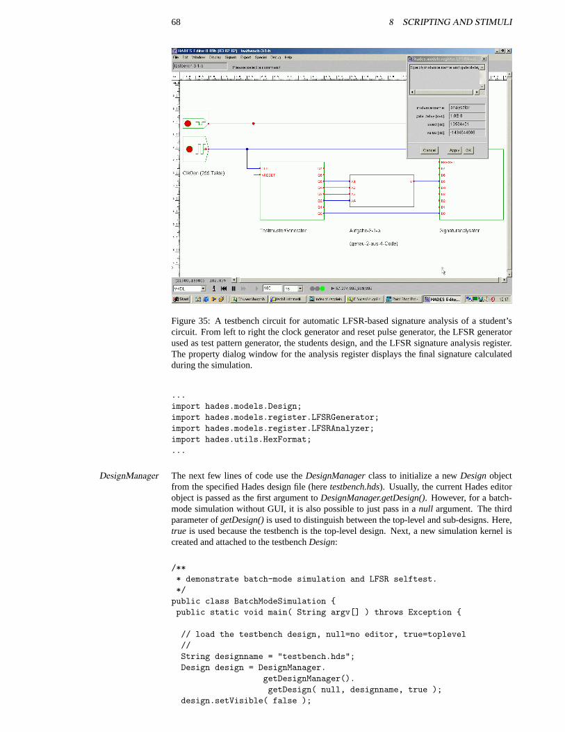
68 8 SCRIPTING AND STIMULI
Figure 35: A testbench circuit for automatic LFSR-based signature analysis of a student’scircuit. From left to right the clock generator and reset pulse generator, the LFSR generatorused as test pattern generator, the students design, and the LFSR signature analysis register.The property dialog window for the analysis register displays the final signature calculatedduring the simulation.
...import hades.models.Design;import hades.models.register.LFSRGenerator;import hades.models.register.LFSRAnalyzer;import hades.utils.HexFormat;...
The next few lines of code use theDesignManagerclass to initialize a newDesignobjectDesignManagerfrom the specified Hades design file (heretestbench.hds). Usually, the current Hades editorobject is passed as the first argument toDesignManager.getDesign(). However, for a batch-mode simulation without GUI, it is also possible to just pass in anull argument. The thirdparameter ofgetDesign()is used to distinguish between the top-level and sub-designs. Here,true is used because the testbench is the top-level design. Next, a new simulation kernel iscreated and attached to the testbenchDesign:
/*** demonstrate batch-mode simulation and LFSR selftest.*/public class BatchModeSimulation {public static void main( String argv[] ) throws Exception {
// load the testbench design, null=no editor, true=toplevel//String designname = "testbench.hds";Design design = DesignManager.
getDesignManager().getDesign( null, designname, true );
design.setVisible( false );
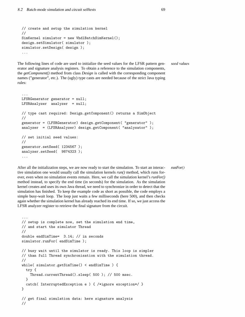
8.2 Batch-mode simulation and circuit selftests 69
// create and setup the simulation kernel//SimKernel simulator = new VhdlBatchSimKernel();design.setSimulator( simulator );simulator.setDesign( design );...
The following lines of code are used to initialize the seed values for the LFSR pattern gen-seed valueserator and signature analysis registers. To obtain a reference to the simulation components,thegetComponent()method from classDesignis called with the corresponding componentnames (”generator”, etc.). The (ugly) type casts are needed because of the strict Java typingrules:
...LFSRGenerator generator = null;LFSRAnalyzer analyzer = null;
// type cast required: Design.getComponent() returns a SimObject//generator = (LFSRGenerator) design.getComponent( "generator" );analyzer = (LFSRAnalyzer) design.getComponent( "analysator" );
// set initial seed values://generator.setSeed( 1234567 );analyzer.setSeed( 9874323 );...
After all the initialization steps, we are now ready to start the simulation. To start an interac-runFor()tive simulation one would usually call the simulation kernelsrun() method, which runs for-ever, even when no simulation events remain. Here, we call the simulation kernel’srunFor()method instead, to specify the end time (in seconds) for the simulation. As the simulationkernel creates and uses its own Java thread, we need to synchronize in order to detect that thesimulation has finished. To keep the example code as short as possible, the code employs asimple busy-wait loop. The loop just waits a few milliseconds (here 500), and then checksagain whether the simulation kernel has already reached its end time. If so, we just access theLFSR analyzer register to retrieve the final signature from the circuit.
...// setup is complete now, set the simulation end time,// and start the simulator Thread//double endSimTime= 3.14; // in secondssimulator.runFor( endSimTime );
// busy wait until the simulator is ready. This loop is simpler// than full Thread synchronisation with the simulation thread.//while( simulator.getSimTime() < endSimTime ) {try {Thread.currentThread().sleep( 500 ); // 500 msec.
}catch( InterruptedException e ) { /*ignore exception*/ }
}
// get final simulation data: here signature analysis//
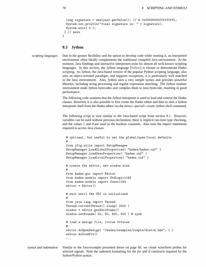
70 8 SCRIPTING AND STIMULI
long signature = analyzer.getValue(); // & 0x00000000ffffffffL;System.out.println("final signature is: " + signature);System.exit( 0 );
} // main}
8.3 Jython
Due to the greater flexibility and the option to develop code while running it, an interpretedscripting languagesenvironment often ideally complements the traditional compiled Java environment. At themoment, Java bindings and interactive interpreters exist for almost all well-known scriptinglanguages. In this section, the Jython language [Jython] is chosen to demonstrate Hadesscripting. As Jython, the Java-based version of the popular Python scripting language, alsouses an object-oriented paradigm, and supports exceptions, it is particularly well matchedto the Java environment. Also, Jython uses a very simple syntax and provides powerfullibraries, including string processing and regular expression matching. The Jython runtimeenvironment reads Jython bytecodes and compiles them to Java bytecode, resulting in goodperformance.
The following code assumes that the Jython interpreter is used to load and control the Hadesclasses. However, it is also possible to first create the Hades editor and then to start a Jythoninterpreter shell from the Hades editor via themenu. special. create Jython shellcommand.
The following script is very similar to the Java-based script from section8.1. However,variables can be used without previous declaration, there is implicit run-time type checking,and the values1 and0 are used as the boolean constants. Also note theimport statementsrequired to access Java classes:
# optional, but useful to set the global/user/local defaults#from jfig.utils import SetupManagerSetupManager.loadGlobalProperties( "hades/hades.cnf" )SetupManager.loadUserProperties( "hades.cnf" )SetupManager.loadLocalProperties( "hades.cnf" )
# create the editor, set window size#from hades.gui import Editorfrom hades.models import StdLogic1164from hades.models import Const1164editor = Editor()
# wait until the GUI is initialized#from java.lang import ThreadThread.currentThread().sleep( 2000 )window = editor.getEditFrame()window.setBounds( 50, 50, 600, 500 ) # xywh
# load a design file, 1=true 0=false#editor.doOpenDesign( "/hades/examples/simple/dlatch.hds", 1 )editor.doZoomFit()...
Similar to the Java-example presented above on page66, we create waveform probes forsyntax and indentationselected signals. Note the indented formatting for thefor and if constructs required by theJython/Python syntax:
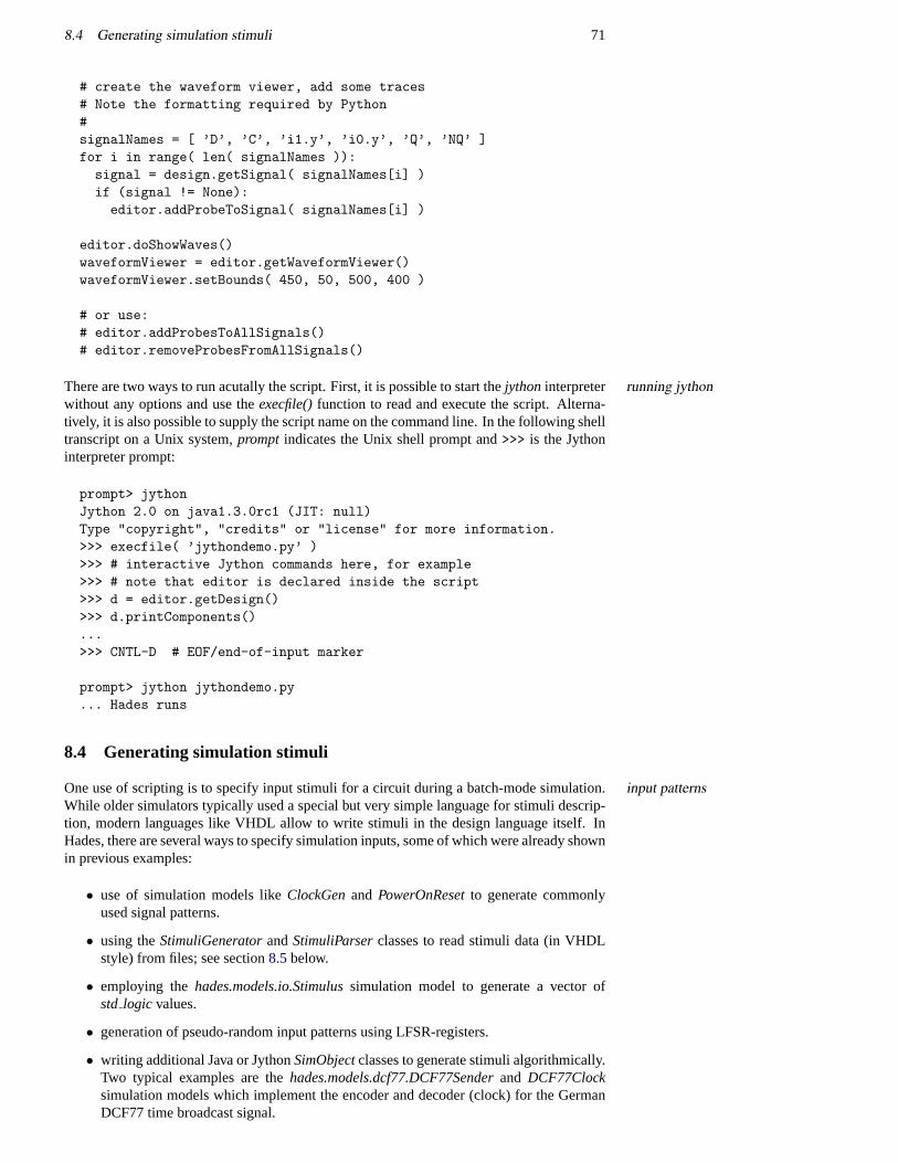
8.4 Generating simulation stimuli 71
# create the waveform viewer, add some traces# Note the formatting required by Python#signalNames = [ ’D’, ’C’, ’i1.y’, ’i0.y’, ’Q’, ’NQ’ ]for i in range( len( signalNames )):signal = design.getSignal( signalNames[i] )if (signal != None):editor.addProbeToSignal( signalNames[i] )
editor.doShowWaves()waveformViewer = editor.getWaveformViewer()waveformViewer.setBounds( 450, 50, 500, 400 )
# or use:# editor.addProbesToAllSignals()# editor.removeProbesFromAllSignals()
There are two ways to run acutally the script. First, it is possible to start thejythoninterpreter running jythonwithout any options and use theexecfile()function to read and execute the script. Alterna-tively, it is also possible to supply the script name on the command line. In the following shelltranscript on a Unix system,prompt indicates the Unix shell prompt and>>> is the Jythoninterpreter prompt:
prompt> jythonJython 2.0 on java1.3.0rc1 (JIT: null)Type "copyright", "credits" or "license" for more information.>>> execfile( ’jythondemo.py’ )>>> # interactive Jython commands here, for example>>> # note that editor is declared inside the script>>> d = editor.getDesign()>>> d.printComponents()...>>> CNTL-D # EOF/end-of-input marker
prompt> jython jythondemo.py... Hades runs
8.4 Generating simulation stimuli
One use of scripting is to specify input stimuli for a circuit during a batch-mode simulation.input patternsWhile older simulators typically used a special but very simple language for stimuli descrip-tion, modern languages like VHDL allow to write stimuli in the design language itself. InHades, there are several ways to specify simulation inputs, some of which were already shownin previous examples:
• use of simulation models likeClockGenand PowerOnResetto generate commonlyused signal patterns.
• using theStimuliGeneratorandStimuliParserclasses to read stimuli data (in VHDLstyle) from files; see section8.5below.
• employing thehades.models.io.Stimulussimulation model to generate a vector ofstd logic values.
• generation of pseudo-random input patterns using LFSR-registers.
• writing additional Java or JythonSimObjectclasses to generate stimuli algorithmically.Two typical examples are thehades.models.dcf77.DCF77Senderand DCF77Clocksimulation models which implement the encoder and decoder (clock) for the GermanDCF77 time broadcast signal.
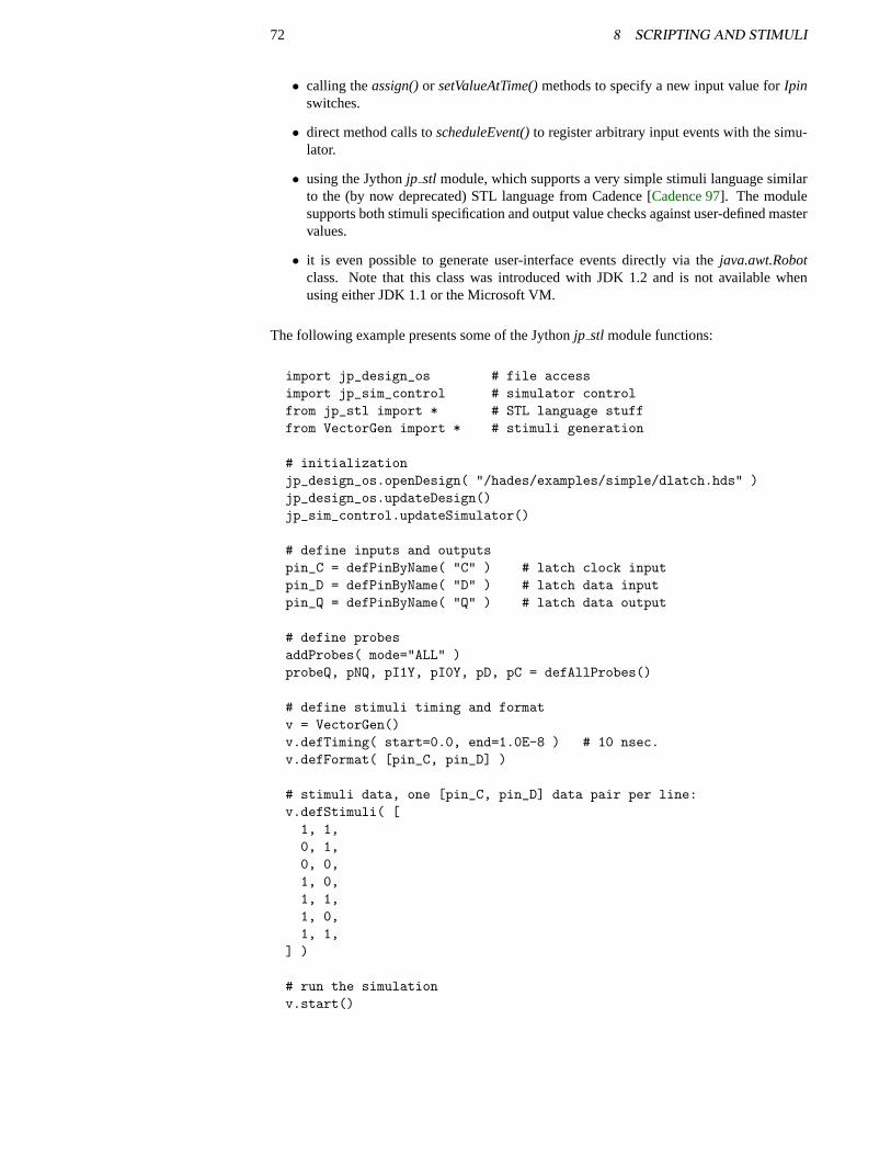
72 8 SCRIPTING AND STIMULI
• calling theassign()or setValueAtTime()methods to specify a new input value forIpinswitches.
• direct method calls toscheduleEvent()to register arbitrary input events with the simu-lator.
• using the Jythonjp stl module, which supports a very simple stimuli language similarto the (by now deprecated) STL language from Cadence [Cadence 97]. The modulesupports both stimuli specification and output value checks against user-defined mastervalues.
• it is even possible to generate user-interface events directly via thejava.awt.Robotclass. Note that this class was introduced with JDK 1.2 and is not available whenusing either JDK 1.1 or the Microsoft VM.
The following example presents some of the Jythonjp stl module functions:
import jp_design_os # file accessimport jp_sim_control # simulator controlfrom jp_stl import * # STL language stufffrom VectorGen import * # stimuli generation
# initializationjp_design_os.openDesign( "/hades/examples/simple/dlatch.hds" )jp_design_os.updateDesign()jp_sim_control.updateSimulator()
# define inputs and outputspin_C = defPinByName( "C" ) # latch clock inputpin_D = defPinByName( "D" ) # latch data inputpin_Q = defPinByName( "Q" ) # latch data output
# define probesaddProbes( mode="ALL" )probeQ, pNQ, pI1Y, pI0Y, pD, pC = defAllProbes()
# define stimuli timing and formatv = VectorGen()v.defTiming( start=0.0, end=1.0E-8 ) # 10 nsec.v.defFormat( [pin_C, pin_D] )
# stimuli data, one [pin_C, pin_D] data pair per line:v.defStimuli( [1, 1,0, 1,0, 0,1, 0,1, 1,1, 0,1, 1,
] )
# run the simulationv.start()
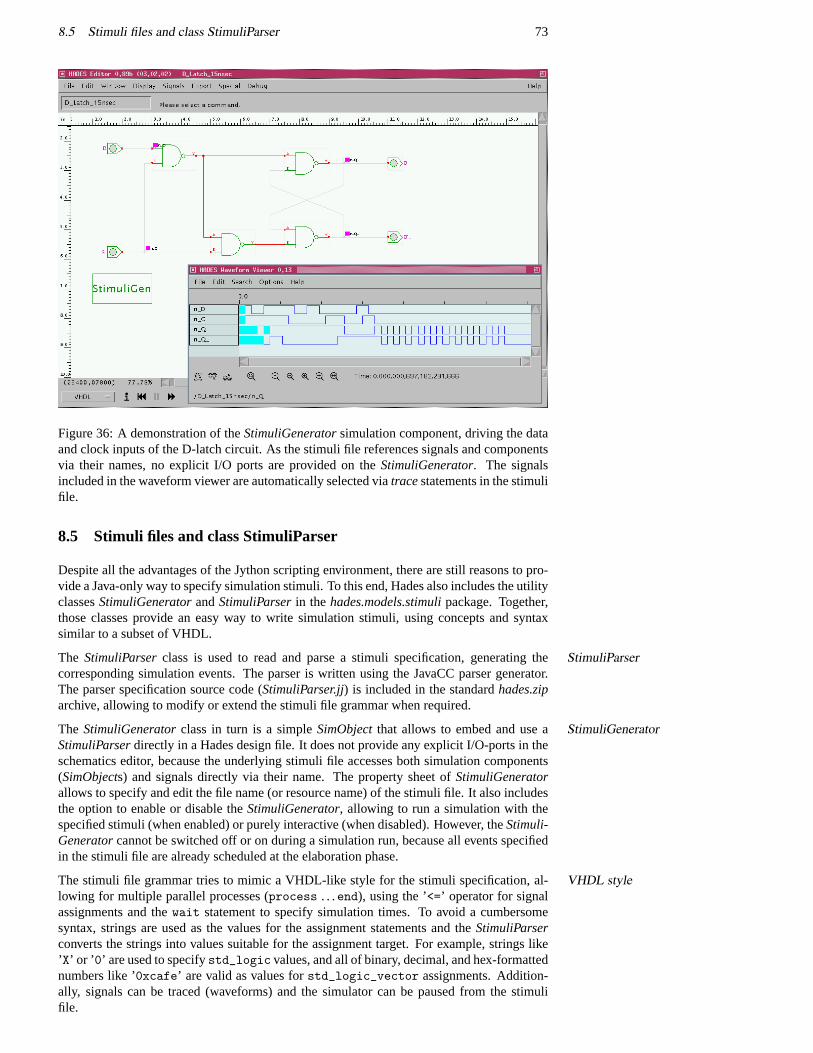
8.5 Stimuli files and class StimuliParser 73
Figure 36: A demonstration of theStimuliGeneratorsimulation component, driving the dataand clock inputs of the D-latch circuit. As the stimuli file references signals and componentsvia their names, no explicit I/O ports are provided on theStimuliGenerator. The signalsincluded in the waveform viewer are automatically selected viatracestatements in the stimulifile.
8.5 Stimuli files and class StimuliParser
Despite all the advantages of the Jython scripting environment, there are still reasons to pro-vide a Java-only way to specify simulation stimuli. To this end, Hades also includes the utilityclassesStimuliGeneratorandStimuliParserin the hades.models.stimulipackage. Together,those classes provide an easy way to write simulation stimuli, using concepts and syntaxsimilar to a subset of VHDL.
The StimuliParserclass is used to read and parse a stimuli specification, generating theStimuliParsercorresponding simulation events. The parser is written using the JavaCC parser generator.The parser specification source code (StimuliParser.jj) is included in the standardhades.ziparchive, allowing to modify or extend the stimuli file grammar when required.
The StimuliGeneratorclass in turn is a simpleSimObjectthat allows to embed and use aStimuliGeneratorStimuliParserdirectly in a Hades design file. It does not provide any explicit I/O-ports in theschematics editor, because the underlying stimuli file accesses both simulation components(SimObjects) and signals directly via their name. The property sheet ofStimuliGeneratorallows to specify and edit the file name (or resource name) of the stimuli file. It also includesthe option to enable or disable theStimuliGenerator, allowing to run a simulation with thespecified stimuli (when enabled) or purely interactive (when disabled). However, theStimuli-Generatorcannot be switched off or on during a simulation run, because all events specifiedin the stimuli file are already scheduled at the elaboration phase.
The stimuli file grammar tries to mimic a VHDL-like style for the stimuli specification, al-VHDL stylelowing for multiple parallel processes (process . . .end), using the ’<=’ operator for signalassignments and thewait statement to specify simulation times. To avoid a cumbersomesyntax, strings are used as the values for the assignment statements and theStimuliParserconverts the strings into values suitable for the assignment target. For example, strings like’X’ or ’ 0’ are used to specifystd_logic values, and all of binary, decimal, and hex-formattednumbers like ’0xcafe’ are valid as values forstd_logic_vector assignments. Addition-ally, signals can be traced (waveforms) and the simulator can be paused from the stimulifile.
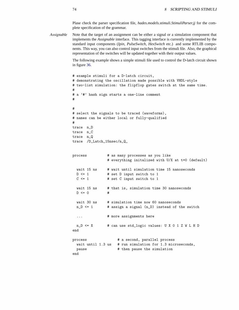
74 8 SCRIPTING AND STIMULI
Plase check the parser specification file,hades.models.stimuli.StimuliParser.jjfor the com-plete specification of the grammar.
Note that the target of an assignment can be either a signal or a simulation component thatAssignableimplements theAssignableinterface. This tagging interface is currently implemented by thestandard input components (Ipin, PulseSwitch, HexSwitchetc.) and some RTLIB compo-nents. This way, you can also control input switches from the stimuli file. Also, the graphicalrepresentation of the switches will be updated together with their output values.
The following example shows a simple stimuli file used to control the D-latch circuit shownin figure36.
# example stimuli for a D-latch circuit,# demonstrating the oscillation made possible with VHDL-style# two-list simulation: the flipflop gates switch at the same time.## a ’#’ hash sign starts a one-line comment#
## select the signals to be traced (waveforms),# names can be either local or fully-qualified#trace n_Dtrace n_Ctrace n_Qtrace /D_Latch_15nsec/n_Q_
process # as many processes as you like# everything initalized with U/X at t=0 (default)
wait 15 ns # wait until simulation time 15 nanosecondsD <= 1 # set D input switch to 1C <= 1 # set C input switch to 1
wait 15 ns # that is, simulation time 30 nanosecondsD <= 0 #
wait 30 ns # simulation time now 60 nanosecondsn_D <= 1 # assign a signal (n_D) instead of the switch
... # more assignments here
n_D <= X # can use std_logic values: U X 0 1 Z W L H Dend
process # a second, parallel processwait until 1.3 us # run simulation for 1.3 microseconds,pause # then pause the simulation
end
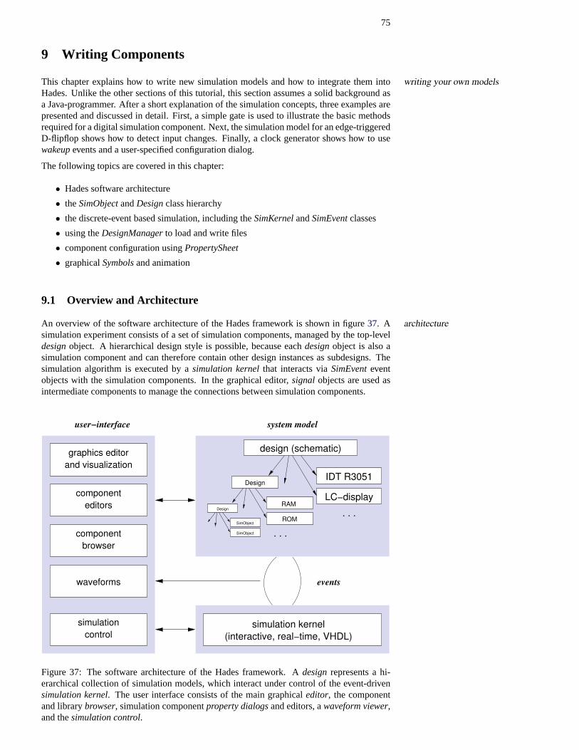
75
9 Writing Components
This chapter explains how to write new simulation models and how to integrate them intowriting your own modelsHades. Unlike the other sections of this tutorial, this section assumes a solid background asa Java-programmer. After a short explanation of the simulation concepts, three examples arepresented and discussed in detail. First, a simple gate is used to illustrate the basic methodsrequired for a digital simulation component. Next, the simulation model for an edge-triggeredD-flipflop shows how to detect input changes. Finally, a clock generator shows how to usewakeupevents and a user-specified configuration dialog.
The following topics are covered in this chapter:
• Hades software architecture
• theSimObjectandDesignclass hierarchy
• the discrete-event based simulation, including theSimKernelandSimEventclasses
• using theDesignManagerto load and write files
• component configuration usingPropertySheet
• graphicalSymbolsand animation
9.1 Overview and Architecture
An overview of the software architecture of the Hades framework is shown in figure37. A architecturesimulation experiment consists of a set of simulation components, managed by the top-leveldesignobject. A hierarchical design style is possible, because eachdesignobject is also asimulation component and can therefore contain other design instances as subdesigns. Thesimulation algorithm is executed by asimulation kernelthat interacts viaSimEventeventobjects with the simulation components. In the graphical editor,signal objects are used asintermediate components to manage the connections between simulation components.
events
simulationcontrol
waveforms
editors
browser
and visualizationgraphics editor
system modeluser−interface
component
component
IDT R3051
ROM
RAM
Design
Design
SimObject
SimObject
. . .
. . .
simulation kernel(interactive, real−time, VHDL)
design (schematic)
LC−display
Figure 37: The software architecture of the Hades framework. Adesignrepresents a hi-erarchical collection of simulation models, which interact under control of the event-drivensimulation kernel. The user interface consists of the main graphicaleditor, the componentand librarybrowser, simulation componentproperty dialogsand editors, awaveform viewer,and thesimulation control.
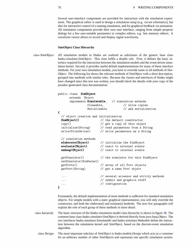
76 9 WRITING COMPONENTS
Several user-interface components are provided for interaction with the simulation experi-ment. The graphicaleditor is used to design a simulation setup (e.g. circuit schematics), butalso for interactive control of a running simulation, and for graphical feedback via animation.All simulation components provide their own user interface, ranging from simple propertydialogs for a few user-settable parameters to complex editors, e.g. hex memory editors. Awaveform viewer allows to record and display signal waveforms.
SimObject Class Hierarchy
All simulation models in Hades are realized as subclasses of the generic base classclass SimObjecthades.simulator.SimObject. This class fulfils a double role. First, it defines the basic in-terface required for the interaction between the simulation models and the event-driven simu-lation kernel. Second, it provides useful default implementations for many of these interfacemethods. For your own simulation models, you have to override some or all methods ofSim-Object. The following list shows the relevant methods ofSimObjectwith a short description,grouped into methods with similar roles. Because the classes and interfaces of Hades mighthave changed since this text was written, you should check the details with your copy of thejavadoc-generated class documentation:
public class SimObjectSimObjectSimObjectextends Objectimplements SimulatableSimulatableSimulatable, // simulation methods
Cloneable, // allow copiesSerializable // and serialization
{{{// object creation and initializationSimObject()SimObject()SimObject() // the default constructorcopy() // get a copy of this objectinitialize(String) // read parameters from a Stringwrite(PrintWriter) // write parameters as a String
// simulation methodselaborate(Object)elaborate(Object)elaborate(Object) // initialize the SimObjectevaluate(Object)evaluate(Object)evaluate(Object) // react to external eventswakeup(Object)wakeup(Object)wakeup(Object) // react to internal events
getSimulator() // the simulator for this SimObjectsetSimulator(SimKernel)getPorts() // array of all Port objectsgetPort(String) // get a name Port object
... // several accessor and utility methods
... // symbol and graphics stuff
... // configuration}}}
Fortunately, the default implementation of most methods is sufficient for standard simulationobjects. For simple models with a static graphical representation, you will only override theconstructor, and both theelaborate()andevaluate()methods. The next few paragraphs willexplain the role of each group of these methods in more detail.
The basic structure of the Hades simulation model class hierarchy is shown in figure38. Theclass hierarchycommon base classhades.simulator.SimObjectis derived directly fromjava.lang.Object. Thetwo interfaceshades.simulator.Simulatableandhades.simulator.Wakeabledefine the interac-tion between the simulation kernel andSimObject, based on the discrete-event simulationalgorithm.
The most important subclass ofSimObjectis hades.models.Designwhich acts as a containerclass Designfor an arbitrary number of otherSimObjectsand represents one specific simulation system.
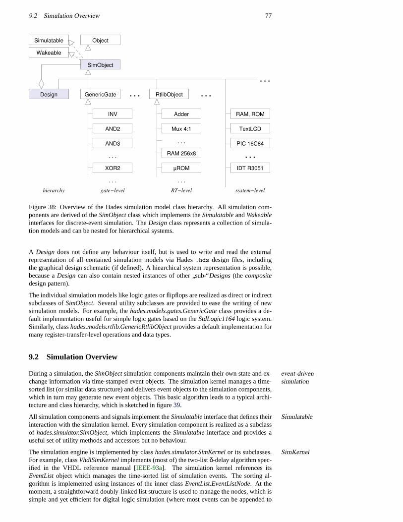
9.2 Simulation Overview 77
XOR2
INV
RAM 256x8
µROM
AND3
Adder
Mux 4:1AND2
GenericGate
. . .
. . .
. . .
. . .
PIC 16C84
TextLCD
ObjectSimulatable
Wakeable
IDT R3051
RtlibObject
hierarchy system−levelRT−levelgate−level
RAM, ROM
Design
SimObject
. . . . . .
. . .
. . .
Figure 38: Overview of the Hades simulation model class hierarchy. All simulation com-ponents are derived of theSimObjectclass which implements theSimulatableandWakeableinterfaces for discrete-event simulation. TheDesignclass represents a collection of simula-tion models and can be nested for hierarchical systems.
A Designdoes not define any behaviour itself, but is used to write and read the externalrepresentation of all contained simulation models via Hades.hds design files, includingthe graphical design schematic (if defined). A hiearchical system representation is possible,because aDesigncan also contain nested instances of other
”sub-“Designs(the composite
design pattern).
The individual simulation models like logic gates or flipflops are realized as direct or indirectsubclasses ofSimObject. Several utility subclasses are provided to ease the writing of newsimulation models. For example, thehades.models.gates.GenericGateclass provides a de-fault implementation useful for simple logic gates based on theStdLogic1164logic system.Similarly, classhades.models.rtlib.GenericRtlibObjectprovides a default implementation formany register-transfer-level operations and data types.
9.2 Simulation Overview
During a simulation, theSimObjectsimulation components maintain their own state and ex-event-drivensimulationchange information via time-stamped event objects. The simulation kernel manages a time-
sorted list (or similar data structure) and delivers event objects to the simulation components,which in turn may generate new event objects. This basic algorithm leads to a typical archi-tecture and class hierarchy, which is sketched in figure39.
All simulation components and signals implement theSimulatableinterface that defines their Simulatableinteraction with the simulation kernel. Every simulation component is realized as a subclassof hades.simulator.SimObject, which implements theSimulatableinterface and provides auseful set of utility methods and accessors but no behaviour.
The simulation engine is implemented by classhades.simulator.SimKernelor its subclasses. SimKernelFor example, classVhdlSimKernelimplements (most of) the two-listδ-delay algorithm spec-ified in the VHDL reference manual [IEEE-93a]. The simulation kernel references itsEventListobject which manages the time-sorted list of simulation events. The sorting al-gorithm is implemented using instances of the inner classEventList.EventListNode. At themoment, a straightforward doubly-linked list structure is used to manage the nodes, which issimple and yet efficient for digital logic simulation (where most events can be appended to
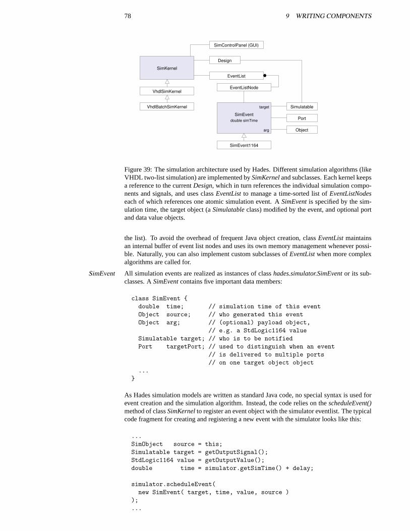
78 9 WRITING COMPONENTS
Object
Simulatable
SimEvent1164
EventListNode
SimKernel
Design
VhdlBatchSimKernel
VhdlSimKernel
EventList
SimControlPanel (GUI)
Port
arg
target
double simTimeSimEvent
Figure 39: The simulation architecture used by Hades. Different simulation algorithms (likeVHDL two-list simulation) are implemented bySimKerneland subclasses. Each kernel keepsa reference to the currentDesign, which in turn references the individual simulation compo-nents and signals, and uses classEventListto manage a time-sorted list ofEventListNodeseach of which references one atomic simulation event. ASimEventis specified by the sim-ulation time, the target object (aSimulatableclass) modified by the event, and optional portand data value objects.
the list). To avoid the overhead of frequent Java object creation, classEventListmaintainsan internal buffer of event list nodes and uses its own memory management whenever possi-ble. Naturally, you can also implement custom subclasses ofEventListwhen more complexalgorithms are called for.
All simulation events are realized as instances of classhades.simulator.SimEventor its sub-SimEventclasses. ASimEventcontains five important data members:
class SimEvent {double time; // simulation time of this eventObject source; // who generated this eventObject arg; // (optional) payload object,
// e.g. a StdLogic1164 valueSimulatable target; // who is to be notifiedPort targetPort; // used to distinguish when an event
// is delivered to multiple ports// on one target object object
...}
As Hades simulation models are written as standard Java code, no special syntax is used forevent creation and the simulation algorithm. Instead, the code relies on thescheduleEvent()method of classSimKernelto register an event object with the simulator eventlist. The typicalcode fragment for creating and registering a new event with the simulator looks like this:
...SimObject source = this;Simulatable target = getOutputSignal();StdLogic1164 value = getOutputValue();double time = simulator.getSimTime() + delay;
simulator.scheduleEvent(new SimEvent( target, time, value, source )
);...
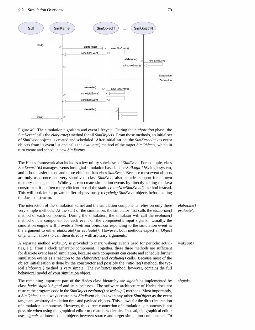
9.2 Simulation Overview 79
...
Elaboration
Simulation
SimObject1 SimObjectNSimKernelGUI
start() elaborate()
scheduleEvent()
new SimEvent()
stop()
new SimEvent()
scheduleEvent()
scheduleEvent()
evaluate()
elaborate()new SimEvent()
scheduleEvent()
evaluate()
Figure 40: The simulation algorithm and event lifecycle. During theelaborationphase, theSimKernelcalls theelaborate()method for allSimObjects. From those methods, an initial setof SimEventobjects is created and scheduled. After initialization, theSimKerneltakes eventobjects from its event list and calls theevaluate()method of the targetSimObjects, which inturn create and schedule newSimEvents.
The Hades framework also includes a few utility subclasses ofSimEvent. For example, classSimEvent1164manages events for digital simulation based on theStdLogic1164logic system,and is both easier to use and more efficient than classSimEvent. Because most event objectsare only used once and very shortlived, classSimEventalso includes support for its ownmemory management. While you can create simulation events by directly calling the Javaconstructor, it is often more efficient to call the staticcreateNewSimEvent()method instead.This will look into a private buffer of previouslyrecycled() SimEventobjects before callingthe Java constructor.
The interaction of the simulation kernel and the simulation components relies on only threeelaborate()evaluate()very simple methods. At the start of the simulation, the simulator first calls theelaborate()
method of each component. During the simulation, the simulator will call theevaluate()method of the component for each event on the component’s input signals. Usually, thesimulation engine will provide aSimEventobject corresponding to the simulation event asthe argument to eitherelaborate()or evaluate(). However, both methods expect anObjectonly, which allows to call them directly with arbitrary arguments.
A separate methodwakeup()is provided to mark wakeup events used for periodic activi-wakeup()ties, e.g. from a clock generator component. Together, these three methods are sufficientfor discrete event based simulation, because each component can create and schedule furthersimulation events as a reaction to theelaborate()andevaluate()calls. Because most of theobject initialization is done by the constructor and possibly theinitialize() method, the typ-ical elaborate()method is very simple. Theevaluate()method, however, contains the fullbehavioral model of your simulation object.
The remaining important part of the Hades class hierarchy aresignalsas implemented by signalsclasshades.signals.Signaland its subclasses. The software architecture of Hades does notrestrict the program code in theSimObject evaluate()orwakeup()methods. Most importantly,a SimObjectcan always create newSimEventobjects with any otherSimObjectas the eventtarget and arbitrary simulation time and payload objects. This allows for the direct interactionof simulation components. However, this direct connection of simulation components is notpossible when using the graphical editor to create new circuits. Instead, the graphical editorusessignalsas intermediate objects between source and target simulation components. To
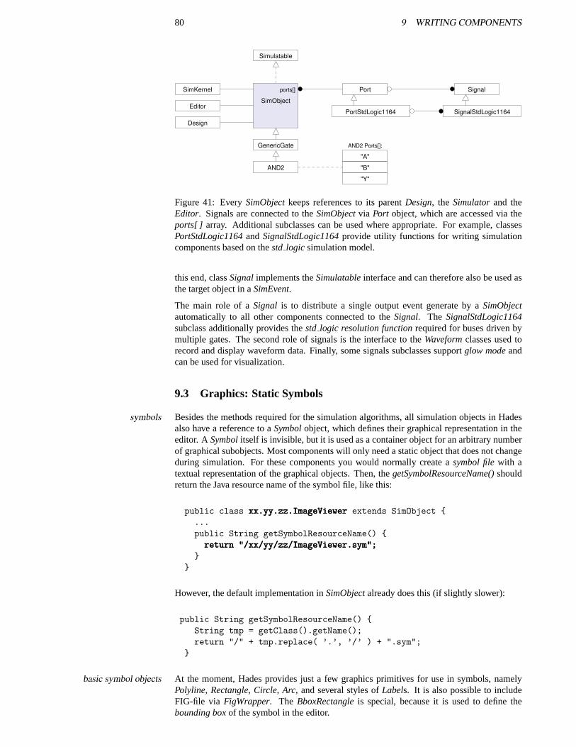
80 9 WRITING COMPONENTS
SimKernel
Simulatable
GenericGate
Editor
AND2
Port
Design
Signal
SignalStdLogic1164
"Y"
PortStdLogic1164
"A"
"B"
SimObject
ports[]
AND2 Ports[]:
Figure 41: EverySimObjectkeeps references to its parentDesign, the Simulatorand theEditor. Signals are connected to theSimObjectvia Port object, which are accessed via theports[ ] array. Additional subclasses can be used where appropriate. For example, classesPortStdLogic1164andSignalStdLogic1164provide utility functions for writing simulationcomponents based on thestd logic simulation model.
this end, classSignalimplements theSimulatableinterface and can therefore also be used asthe target object in aSimEvent.
The main role of aSignal is to distribute a single output event generate by aSimObjectautomatically to all other components connected to theSignal. The SignalStdLogic1164subclass additionally provides thestd logic resolution functionrequired for buses driven bymultiple gates. The second role of signals is the interface to theWaveformclasses used torecord and display waveform data. Finally, some signals subclasses supportglow modeandcan be used for visualization.
9.3 Graphics: Static Symbols
Besides the methods required for the simulation algorithms, all simulation objects in Hadessymbolsalso have a reference to aSymbolobject, which defines their graphical representation in theeditor. ASymbolitself is invisible, but it is used as a container object for an arbitrary numberof graphical subobjects. Most components will only need a static object that does not changeduring simulation. For these components you would normally create asymbol filewith atextual representation of the graphical objects. Then, thegetSymbolResourceName()shouldreturn the Java resource name of the symbol file, like this:
public class xx.yy.zz.ImageViewerxx.yy.zz.ImageViewerxx.yy.zz.ImageViewer extends SimObject {...public String getSymbolResourceName() {return "/xx/yy/zz/ImageViewer.sym";return "/xx/yy/zz/ImageViewer.sym";return "/xx/yy/zz/ImageViewer.sym";
}}
However, the default implementation inSimObjectalready does this (if slightly slower):
public String getSymbolResourceName() {String tmp = getClass().getName();return "/" + tmp.replace( ’.’, ’/’ ) + ".sym";
}
At the moment, Hades provides just a few graphics primitives for use in symbols, namelybasic symbol objectsPolyline, Rectangle, Circle, Arc, and several styles ofLabels. It is also possible to includeFIG-file via FigWrapper. The BboxRectangleis special, because it is used to define thebounding boxof the symbol in the editor.
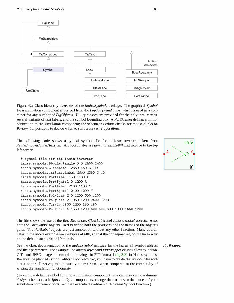
9.3 Graphics: Static Symbols 81
hades.symbols
jfig.objects
InstanceLabel
Label
PortSymbol
ImageObject
FigWrapper
FigObject
ClassLabel
PortLabel
FigText
FigBaseobject
SimObject
BboxRectangle
FigCompound
Symbol
Figure 42: Class hierarchy overview of thehades.symbolspackage. The graphicalSymbolfor a simulation component is derived from theFigCompoundclass, which is used as a con-tainer for any number ofFigObjects. Utility classes are provided for the polylines, circles,several variants of text labels, and the symbol bounding box. APortSymboldefines a pin forconnection to the simulation component; the schematics editor checks for mouse-clicks onPortSymbolpositions to decide when to startcreate wireoperations.
The following code shows a typical symbol file for a basic inverter, taken from/hades/models/gates/Inv.sym. All coordinates are given in inch/2400 and relative to the topleft corner:
# symbol file for the basic inverterhades.symbols.BboxRectangle 0 0 2400 2400hades.symbols.ClassLabel 2350 450 3 INVhades.symbols.InstanceLabel 2350 2350 3 i0hades.symbols.PortLabel 150 1130 Ahades.symbols.PortSymbol 0 1200 Ahades.symbols.PortLabel 2100 1130 Yhades.symbols.PortSymbol 2400 1200 Yhades.symbols.Polyline 2 0 1200 600 1200hades.symbols.Polyline 2 1950 1200 2400 1200hades.symbols.Circle 1800 1200 150 150hades.symbols.Polyline 4 1650 1200 600 600 600 1800 1650 1200
The file shows the use of theBboxRectangle, ClassLabeland InstanceLabelobjects. Also,note thePortSymbolobjects, used to define both the positions and the names of the object’sports. ThePortLabelobjects are just annotation without any other function. Many coordi-nates in the above example are multiples of 600, so that the corresponding points lie exactlyon the default snap grid of 1/4th inch.
See the class documentation of thehades.symbolpackage for the list of all symbol objects FigWrapperand their parameters. For example, theImageObjectandFigWrapperclasses allow to includeGIF- and JPEG-images or complete drawings in FIG-format [xfig 3.2] in Hades symbols.Because the planned symbol editor is not ready yet, you have to create the symbol files witha text editor. However, this is usually a simple task when compared to the complexity ofwriting the simulation functionality.
(To create a default symbol for a new simulation component, you can also create a dummydesignschematic, addIpin andOpin components, change their names to the names of yoursimulation component ports, and then execute the editorEdit. Create Symbolfunction.)
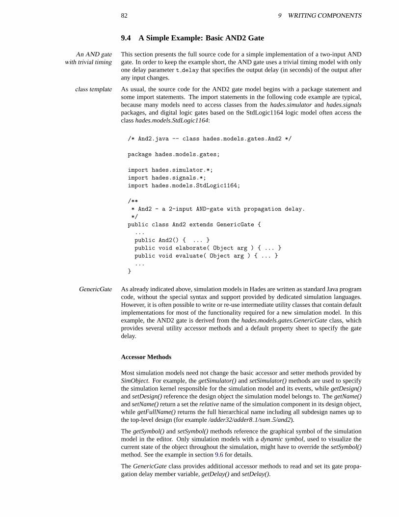
82 9 WRITING COMPONENTS
9.4 A Simple Example: Basic AND2 Gate
This section presents the full source code for a simple implementation of a two-input ANDAn AND gatewith trivial timing gate. In order to keep the example short, the AND gate uses a trivial timing model with only
one delay parametert delay that specifies the output delay (in seconds) of the output afterany input changes.
As usual, the source code for the AND2 gate model begins with a package statement andclass templatesome import statements. The import statements in the following code example are typical,because many models need to access classes from thehades.simulatorand hades.signalspackages, and digital logic gates based on the StdLogic1164 logic model often access theclasshades.models.StdLogic1164:
/* And2.java -- class hades.models.gates.And2 */
package hades.models.gates;
import hades.simulator.*;import hades.signals.*;import hades.models.StdLogic1164;
/*** And2 - a 2-input AND-gate with propagation delay.*/
public class And2 extends GenericGate {...public And2() { ... }public void elaborate( Object arg ) { ... }public void evaluate( Object arg ) { ... }...
}
As already indicated above, simulation models in Hades are written as standard Java programGenericGatecode, without the special syntax and support provided by dedicated simulation languages.However, it is often possible to write or re-use intermediate utility classes that contain defaultimplementations for most of the functionality required for a new simulation model. In thisexample, the AND2 gate is derived from thehades.models.gates.GenericGateclass, whichprovides several utility accessor methods and a default property sheet to specify the gatedelay.
Accessor Methods
Most simulation models need not change the basic accessor and setter methods provided bySimObject. For example, thegetSimulator()andsetSimulator()methods are used to specifythe simulation kernel responsible for the simulation model and its events, whilegetDesign()andsetDesign()reference the design object the simulation model belongs to. ThegetName()andsetName()return a set therelativename of the simulation component in its design object,while getFullName()returns the full hierarchical name including all subdesign names up tothe top-level design (for example/adder32/adder81/sum5/and2).
ThegetSymbol()andsetSymbol()methods reference the graphical symbol of the simulationmodel in the editor. Only simulation models with adynamic symbol, used to visualize thecurrent state of the object throughout the simulation, might have to override thesetSymbol()method. See the example in section9.6for details.
TheGenericGateclass provides additional accessor methods to read and set its gate propa-gation delay member variable,getDelay()andsetDelay().
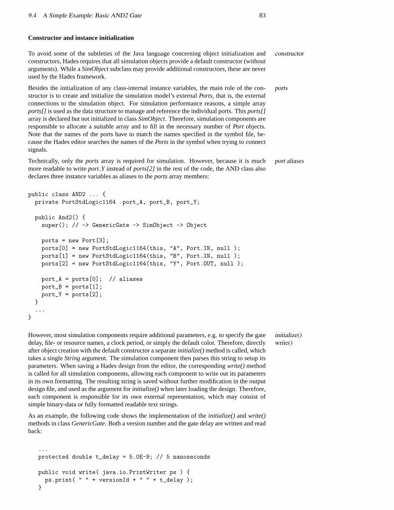
9.4 A Simple Example: Basic AND2 Gate 83
Constructor and instance initialization
To avoid some of the subtleties of the Java language concerning object initialization andconstructorconstructors, Hades requires that all simulation objects provide a default constructor (withoutarguments). While aSimObjectsubclass may provide additional constructors, these are neverused by the Hades framework.
Besides the initialization of any class-internal instance variables, the main role of the con-portsstructor is to create and initialize the simulation model’s externalPorts, that is, the externalconnections to the simulation object. For simulation performance reasons, a simple arrayports[] is used as the data structure to manage and reference the individual ports. Thisports[]array is declared but not initialized in classSimObject. Therefore, simulation components areresponsible to allocate a suitable array and to fill in the necessary number ofPort objects.Note that the names of the ports have to match the names specified in the symbol file, be-cause the Hades editor searches the names of thePorts in the symbol when trying to connectsignals.
Technically, only theports array is required for simulation. However, because it is muchport aliasesmore readable to writeport Y instead ofports[2] in the rest of the code, the AND class alsodeclares three instance variables as aliases to theportsarray members:
public class AND2 ... {private PortStdLogic1164 port_A, port_B, port_Y;
public And2() {super(); // -> GenericGate -> SimObject -> Object
ports = new Port[3];ports[0] = new PortStdLogic1164(this, "A", Port.IN, null );ports[1] = new PortStdLogic1164(this, "B", Port.IN, null );ports[2] = new PortStdLogic1164(this, "Y", Port.OUT, null );
port_A = ports[0]; // aliasesport_B = ports[1];port_Y = ports[2];
}...
}
However, most simulation components require additional parameters, e.g. to specify the gateinitialize()write()delay, file- or resource names, a clock period, or simply the default color. Therefore, directly
after object creation with the default constructor a separateinitialize() method is called, whichtakes a singleStringargument. The simulation component then parses this string to setup itsparameters. When saving a Hades design from the editor, the correspondingwrite() methodis called for all simulation components, allowing each component to write out its parametersin its own formatting. The resulting string is saved without further modification in the outputdesign file, and used as the argument forinitialize() when later loading the design. Therefore,each component is responsible for its own external representation, which may consist ofsimple binary-data or fully formatted readable text strings.
As an example, the following code shows the implementation of theinitialize() andwrite()methods in classGenericGate. Both a version number and the gate delay are written and readback:
...protected double t_delay = 5.0E-9; // 5 nanoseconds
public void write( java.io.PrintWriter ps ) {ps.print( " " + versionId + " " + t_delay );
}
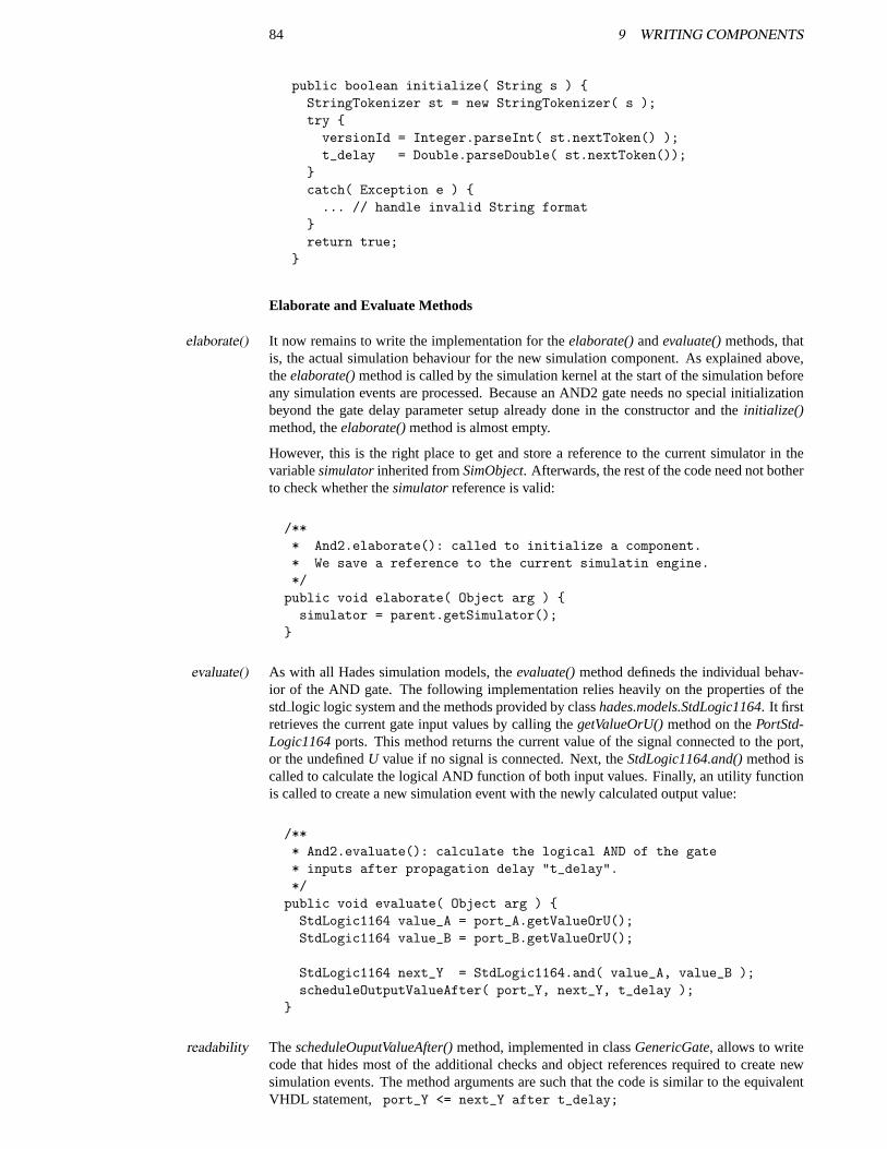
84 9 WRITING COMPONENTS
public boolean initialize( String s ) {StringTokenizer st = new StringTokenizer( s );try {versionId = Integer.parseInt( st.nextToken() );t_delay = Double.parseDouble( st.nextToken());
}catch( Exception e ) {... // handle invalid String format
}return true;
}
Elaborate and Evaluate Methods
It now remains to write the implementation for theelaborate()andevaluate()methods, thatelaborate()is, the actual simulation behaviour for the new simulation component. As explained above,theelaborate()method is called by the simulation kernel at the start of the simulation beforeany simulation events are processed. Because an AND2 gate needs no special initializationbeyond the gate delay parameter setup already done in the constructor and theinitialize()method, theelaborate()method is almost empty.
However, this is the right place to get and store a reference to the current simulator in thevariablesimulatorinherited fromSimObject. Afterwards, the rest of the code need not botherto check whether thesimulatorreference is valid:
/*** And2.elaborate(): called to initialize a component.* We save a reference to the current simulatin engine.*/public void elaborate( Object arg ) {simulator = parent.getSimulator();
}
As with all Hades simulation models, theevaluate()method defineds the individual behav-evaluate()ior of the AND gate. The following implementation relies heavily on the properties of thestd logic logic system and the methods provided by classhades.models.StdLogic1164. It firstretrieves the current gate input values by calling thegetValueOrU()method on thePortStd-Logic1164ports. This method returns the current value of the signal connected to the port,or the undefinedU value if no signal is connected. Next, theStdLogic1164.and()method iscalled to calculate the logical AND function of both input values. Finally, an utility functionis called to create a new simulation event with the newly calculated output value:
/*** And2.evaluate(): calculate the logical AND of the gate* inputs after propagation delay "t_delay".*/public void evaluate( Object arg ) {StdLogic1164 value_A = port_A.getValueOrU();StdLogic1164 value_B = port_B.getValueOrU();
StdLogic1164 next_Y = StdLogic1164.and( value_A, value_B );scheduleOutputValueAfter( port_Y, next_Y, t_delay );
}
ThescheduleOuputValueAfter()method, implemented in classGenericGate, allows to writereadabilitycode that hides most of the additional checks and object references required to create newsimulation events. The method arguments are such that the code is similar to the equivalentVHDL statement, port_Y <= next_Y after t_delay;
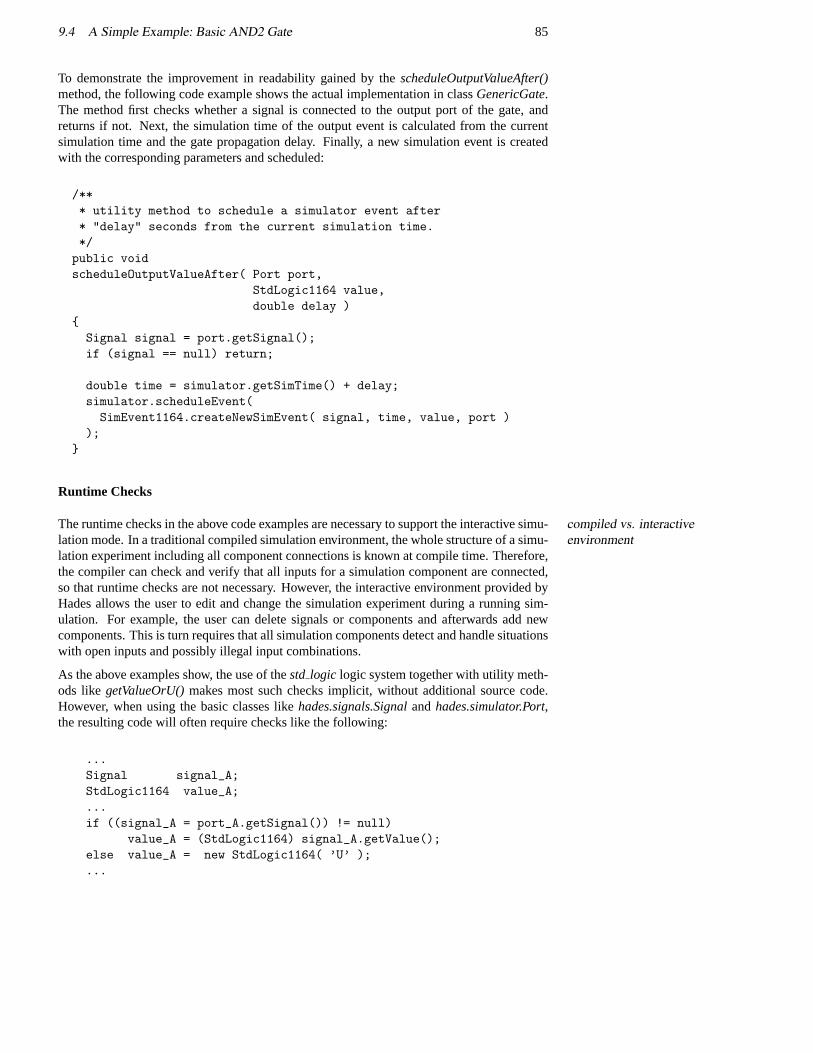
9.4 A Simple Example: Basic AND2 Gate 85
To demonstrate the improvement in readability gained by thescheduleOutputValueAfter()method, the following code example shows the actual implementation in classGenericGate.The method first checks whether a signal is connected to the output port of the gate, andreturns if not. Next, the simulation time of the output event is calculated from the currentsimulation time and the gate propagation delay. Finally, a new simulation event is createdwith the corresponding parameters and scheduled:
/*** utility method to schedule a simulator event after* "delay" seconds from the current simulation time.*/
public voidscheduleOutputValueAfter( Port port,
StdLogic1164 value,double delay )
{Signal signal = port.getSignal();if (signal == null) return;
double time = simulator.getSimTime() + delay;simulator.scheduleEvent(SimEvent1164.createNewSimEvent( signal, time, value, port )
);}
Runtime Checks
The runtime checks in the above code examples are necessary to support the interactive simu-compiled vs. interactiveenvironmentlation mode. In a traditional compiled simulation environment, the whole structure of a simu-
lation experiment including all component connections is known at compile time. Therefore,the compiler can check and verify that all inputs for a simulation component are connected,so that runtime checks are not necessary. However, the interactive environment provided byHades allows the user to edit and change the simulation experiment during a running sim-ulation. For example, the user can delete signals or components and afterwards add newcomponents. This is turn requires that all simulation components detect and handle situationswith open inputs and possibly illegal input combinations.
As the above examples show, the use of thestd logic logic system together with utility meth-ods likegetValueOrU()makes most such checks implicit, without additional source code.However, when using the basic classes likehades.signals.Signalandhades.simulator.Port,the resulting code will often require checks like the following:
...Signal signal_A;StdLogic1164 value_A;...if ((signal_A = port_A.getSignal()) != null)
value_A = (StdLogic1164) signal_A.getValue();else value_A = new StdLogic1164( ’U’ );...
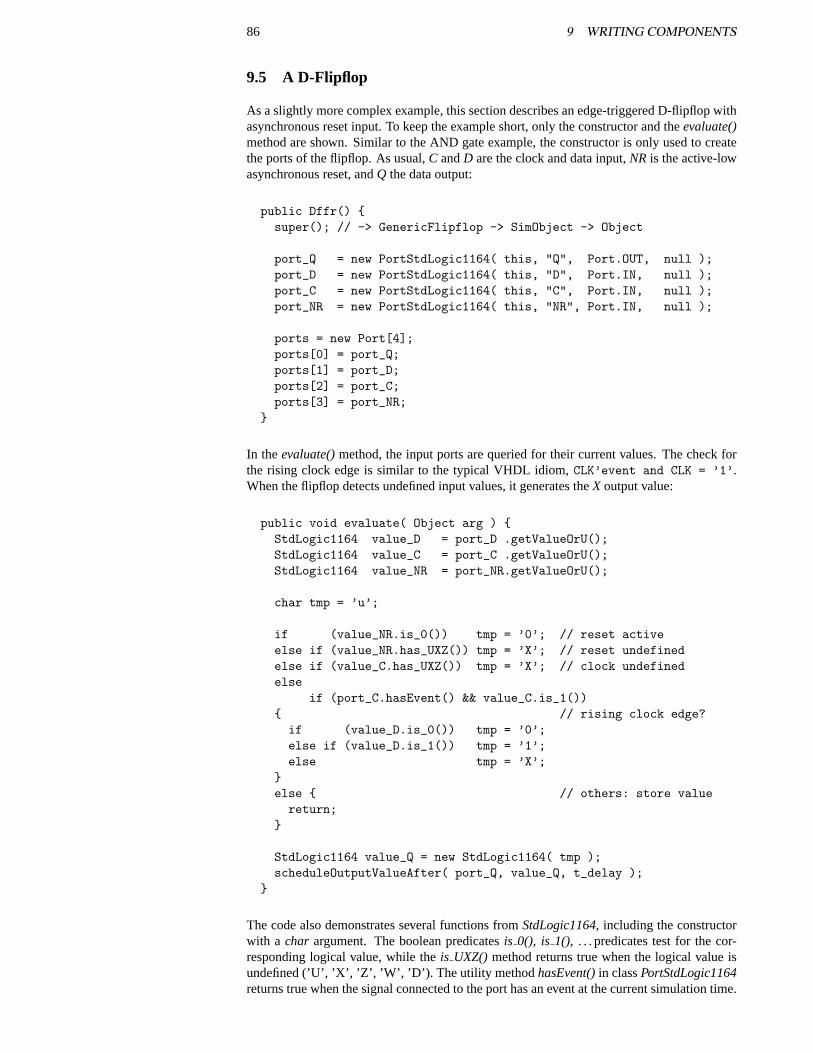
86 9 WRITING COMPONENTS
9.5 A D-Flipflop
As a slightly more complex example, this section describes an edge-triggered D-flipflop withasynchronous reset input. To keep the example short, only the constructor and theevaluate()method are shown. Similar to the AND gate example, the constructor is only used to createthe ports of the flipflop. As usual,C andD are the clock and data input,NR is the active-lowasynchronous reset, andQ the data output:
public Dffr() {super(); // -> GenericFlipflop -> SimObject -> Object
port_Q = new PortStdLogic1164( this, "Q", Port.OUT, null );port_D = new PortStdLogic1164( this, "D", Port.IN, null );port_C = new PortStdLogic1164( this, "C", Port.IN, null );port_NR = new PortStdLogic1164( this, "NR", Port.IN, null );
ports = new Port[4];ports[0] = port_Q;ports[1] = port_D;ports[2] = port_C;ports[3] = port_NR;
}
In theevaluate()method, the input ports are queried for their current values. The check forthe rising clock edge is similar to the typical VHDL idiom,CLK’event and CLK = ’1’.When the flipflop detects undefined input values, it generates theX output value:
public void evaluate( Object arg ) {StdLogic1164 value_D = port_D .getValueOrU();StdLogic1164 value_C = port_C .getValueOrU();StdLogic1164 value_NR = port_NR.getValueOrU();
char tmp = ’u’;
if (value_NR.is_0()) tmp = ’0’; // reset activeelse if (value_NR.has_UXZ()) tmp = ’X’; // reset undefinedelse if (value_C.has_UXZ()) tmp = ’X’; // clock undefinedelse
if (port_C.hasEvent() && value_C.is_1()){ // rising clock edge?
if (value_D.is_0()) tmp = ’0’;else if (value_D.is_1()) tmp = ’1’;else tmp = ’X’;
}else { // others: store value
return;}
StdLogic1164 value_Q = new StdLogic1164( tmp );scheduleOutputValueAfter( port_Q, value_Q, t_delay );
}
The code also demonstrates several functions fromStdLogic1164, including the constructorwith a char argument. The boolean predicatesis 0(), is 1(), . . . predicates test for the cor-responding logical value, while theis UXZ() method returns true when the logical value isundefined (’U’, ’X’, ’Z’, ’W’, ’D’). The utility method hasEvent()in classPortStdLogic1164returns true when the signal connected to the port has an event at the current simulation time.
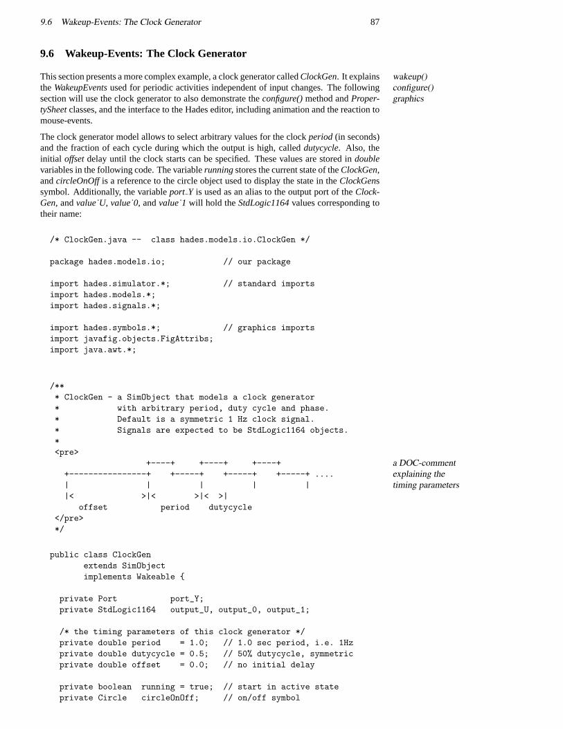
9.6 Wakeup-Events: The Clock Generator 87
9.6 Wakeup-Events: The Clock Generator
This section presents a more complex example, a clock generator calledClockGen. It explains wakeup()configure()graphics
theWakeupEventsused for periodic activities independent of input changes. The followingsection will use the clock generator to also demonstrate theconfigure()method andProper-tySheetclasses, and the interface to the Hades editor, including animation and the reaction tomouse-events.
The clock generator model allows to select arbitrary values for the clockperiod(in seconds)and the fraction of each cycle during which the output is high, calleddutycycle. Also, theinitial offsetdelay until the clock starts can be specified. These values are stored indoublevariables in the following code. The variablerunningstores the current state of theClockGen,andcircleOnOffis a reference to the circle object used to display the state in theClockGenssymbol. Additionally, the variableport Y is used as an alias to the output port of theClock-Gen, andvalue˙U, value˙0, andvalue˙1will hold the StdLogic1164values corresponding totheir name:
/* ClockGen.java -- class hades.models.io.ClockGen */
package hades.models.io; // our package
import hades.simulator.*; // standard importsimport hades.models.*;import hades.signals.*;
import hades.symbols.*; // graphics importsimport javafig.objects.FigAttribs;import java.awt.*;
/*** ClockGen - a SimObject that models a clock generator* with arbitrary period, duty cycle and phase.* Default is a symmetric 1 Hz clock signal.* Signals are expected to be StdLogic1164 objects.*<pre>
+----+ +----+ +----+ a DOC-commentexplaining thetiming parameters
+----------------+ +-----+ +-----+ +-----+ ....| | | | ||< >|< >|< >|
offset period dutycycle</pre>*/
public class ClockGenextends SimObjectimplements Wakeable {
private Port port_Y;private StdLogic1164 output_U, output_0, output_1;
/* the timing parameters of this clock generator */private double period = 1.0; // 1.0 sec period, i.e. 1Hzprivate double dutycycle = 0.5; // 50% dutycycle, symmetricprivate double offset = 0.0; // no initial delay
private boolean running = true; // start in active stateprivate Circle circleOnOff; // on/off symbol
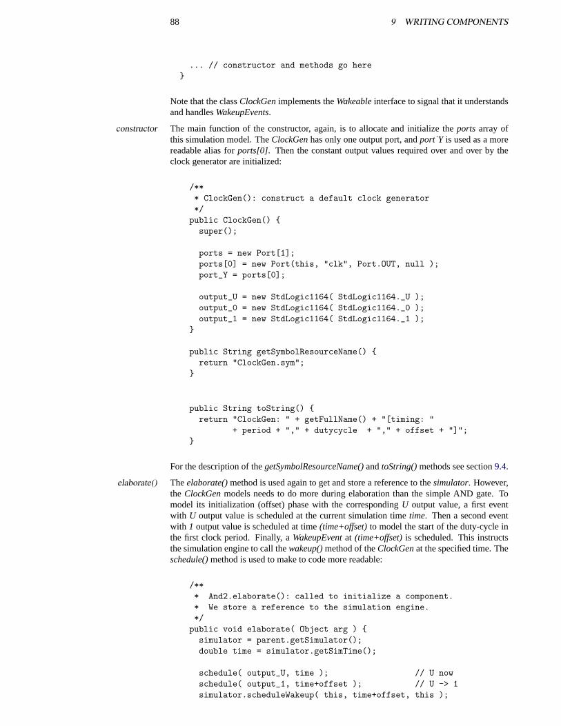
88 9 WRITING COMPONENTS
... // constructor and methods go here}
Note that the classClockGenimplements theWakeableinterface to signal that it understandsand handlesWakeupEvents.
The main function of the constructor, again, is to allocate and initialize theports array ofconstructorthis simulation model. TheClockGenhas only one output port, andport˙Y is used as a morereadable alias forports[0]. Then the constant output values required over and over by theclock generator are initialized:
/*** ClockGen(): construct a default clock generator*/
public ClockGen() {super();
ports = new Port[1];ports[0] = new Port(this, "clk", Port.OUT, null );port_Y = ports[0];
output_U = new StdLogic1164( StdLogic1164._U );output_0 = new StdLogic1164( StdLogic1164._0 );output_1 = new StdLogic1164( StdLogic1164._1 );
}
public String getSymbolResourceName() {return "ClockGen.sym";
}
public String toString() {return "ClockGen: " + getFullName() + "[timing: "
+ period + "," + dutycycle + "," + offset + "]";}
For the description of thegetSymbolResourceName()andtoString()methods see section9.4.
Theelaborate()method is used again to get and store a reference to thesimulator. However,elaborate()the ClockGenmodels needs to do more during elaboration than the simple AND gate. Tomodel its initialization (offset) phase with the correspondingU output value, a first eventwith U output value is scheduled at the current simulation timetime. Then a second eventwith 1 output value is scheduled at time(time+offset)to model the start of the duty-cycle inthe first clock period. Finally, aWakeupEventat (time+offset)is scheduled. This instructsthe simulation engine to call thewakeup()method of theClockGenat the specified time. Theschedule()method is used to make to code more readable:
/*** And2.elaborate(): called to initialize a component.* We store a reference to the simulation engine.*/
public void elaborate( Object arg ) {simulator = parent.getSimulator();double time = simulator.getSimTime();
schedule( output_U, time ); // U nowschedule( output_1, time+offset ); // U -> 1simulator.scheduleWakeup( this, time+offset, this );
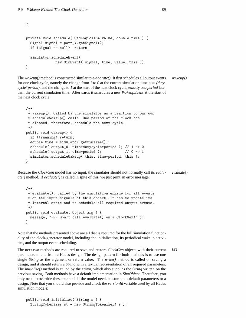
9.6 Wakeup-Events: The Clock Generator 89
}
private void schedule( StdLogic1164 value, double time ) {Signal signal = port_Y.getSignal();if (signal == null) return;
simulator.scheduleEvent(new SimEvent( signal, time, value, this ));
}
Thewakeup()method is constructed similar toelaborate(). It first schedules all output events wakeup()for one clock cycle, namely the change from1 to 0 at the current simulation time plus(duty-cycle*period), and the change to1 at the start of the next clock cycle, exactly oneperiodlaterthan the current simulation time. Afterwards it schedules a newWakeupEventat the start ofthe next clock cycle:
/*** wakeup(): Called by the simulator as a reaction to our own* scheduleWakeup()-calls. One period of the clock has* elapsed, therefore, schedule the next cycle.*/public void wakeup() {if (!running) return;double time = simulator.getSimTime();schedule( output_0, time+dutycycle*period ); // 1 -> 0schedule( output_1, time+period ); // 0 -> 1simulator.scheduleWakeup( this, time+period, this );
}
Because theClockGenmodel has no input, the simulator should not normally call itsevalu- evaluate()ate()method. Ifevaluate()is called in spite of this, we just print an error message:
/*** evaluate(): called by the simulation engine for all events* on the input signals of this object. It has to update its* internal state and to schedule all required output events.*/public void evaluate( Object arg ) {message( "-E- Don’t call evaluate() on a ClockGen!" );
}
Note that the methods presented above are all that is required for the full simulation function-ality of the clock-generator model, including the initialization, its periodical wakeup activi-ties, and the output event scheduling.
The next two methods are required to save and restoreClockGenobjects with their current I/Oparameters to and from a Hades design. The design pattern for both methods is to use onesingle String as the argument or return value. Thewrite() method is called on saving adesign, and it should return aStringwith a textual representation of all required parameters.The initialize() method is called by the editor, which also supplies theStringwritten on theprevious saving. Both methods have a default implementation inSimObject. Therefore, youonly need to override these methods if the model needs to store non-default parameters to adesign. Note that you should also provide and check theversionIdvariable used by all Hadessimulation models:
public void initialize( String s ) {StringTokenizer st = new StringTokenizer( s );
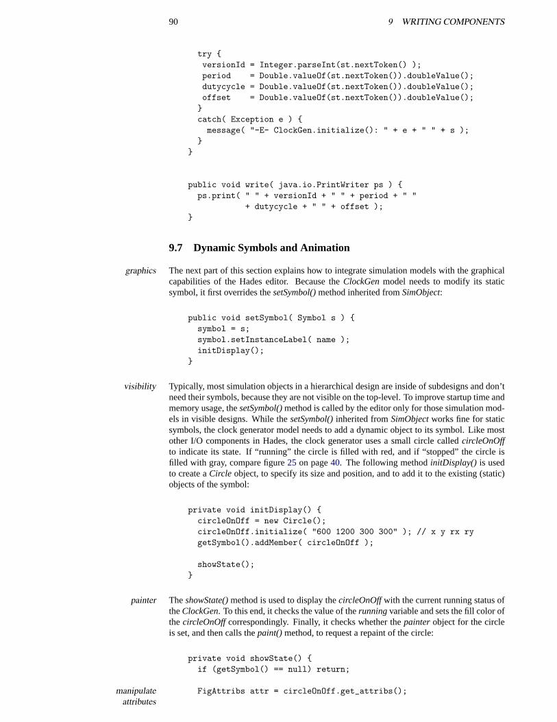
90 9 WRITING COMPONENTS
try {versionId = Integer.parseInt(st.nextToken() );period = Double.valueOf(st.nextToken()).doubleValue();dutycycle = Double.valueOf(st.nextToken()).doubleValue();offset = Double.valueOf(st.nextToken()).doubleValue();}catch( Exception e ) {message( "-E- ClockGen.initialize(): " + e + " " + s );
}}
public void write( java.io.PrintWriter ps ) {ps.print( " " + versionId + " " + period + " "
+ dutycycle + " " + offset );}
9.7 Dynamic Symbols and Animation
The next part of this section explains how to integrate simulation models with the graphicalgraphicscapabilities of the Hades editor. Because theClockGenmodel needs to modify its staticsymbol, it first overrides thesetSymbol()method inherited fromSimObject:
public void setSymbol( Symbol s ) {symbol = s;symbol.setInstanceLabel( name );initDisplay();
}
Typically, most simulation objects in a hierarchical design are inside of subdesigns and don’tvisibilityneed their symbols, because they are not visible on the top-level. To improve startup time andmemory usage, thesetSymbol()method is called by the editor only for those simulation mod-els in visible designs. While thesetSymbol()inherited fromSimObjectworks fine for staticsymbols, the clock generator model needs to add a dynamic object to its symbol. Like mostother I/O components in Hades, the clock generator uses a small circle calledcircleOnOffto indicate its state. If “running” the circle is filled with red, and if “stopped” the circle isfilled with gray, compare figure25 on page40. The following methodinitDisplay() is usedto create aCircle object, to specify its size and position, and to add it to the existing (static)objects of the symbol:
private void initDisplay() {circleOnOff = new Circle();circleOnOff.initialize( "600 1200 300 300" ); // x y rx rygetSymbol().addMember( circleOnOff );
showState();}
TheshowState()method is used to display thecircleOnOffwith the current running status ofpaintertheClockGen. To this end, it checks the value of therunningvariable and sets the fill color ofthecircleOnOffcorrespondingly. Finally, it checks whether thepainterobject for the circleis set, and then calls thepaint()method, to request a repaint of the circle:
private void showState() {if (getSymbol() == null) return;
FigAttribs attr = circleOnOff.get_attribs();manipulateattributes
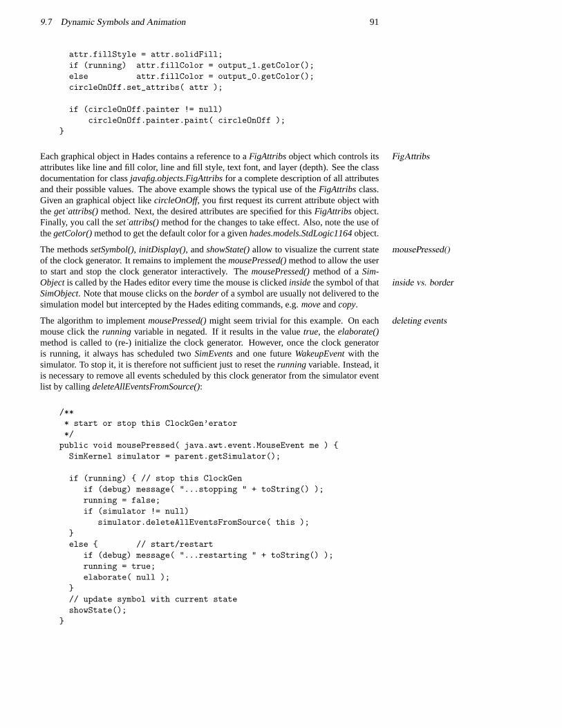
9.7 Dynamic Symbols and Animation 91
attr.fillStyle = attr.solidFill;if (running) attr.fillColor = output_1.getColor();else attr.fillColor = output_0.getColor();circleOnOff.set_attribs( attr );
if (circleOnOff.painter != null)circleOnOff.painter.paint( circleOnOff );
}
Each graphical object in Hades contains a reference to aFigAttribs object which controls its FigAttribsattributes like line and fill color, line and fill style, text font, and layer (depth). See the classdocumentation for classjavafig.objects.FigAttribsfor a complete description of all attributesand their possible values. The above example shows the typical use of theFigAttribs class.Given an graphical object likecircleOnOff, you first request its current attribute object withtheget˙attribs()method. Next, the desired attributes are specified for thisFigAttribs object.Finally, you call theset˙attribs()method for the changes to take effect. Also, note the use ofthegetColor()method to get the default color for a givenhades.models.StdLogic1164object.
The methodssetSymbol(), initDisplay(), andshowState()allow to visualize the current state mousePressed()of the clock generator. It remains to implement themousePressed()method to allow the userto start and stop the clock generator interactively. ThemousePressed()method of aSim-Objectis called by the Hades editor every time the mouse is clickedinsidethe symbol of that inside vs. borderSimObject. Note that mouse clicks on theborderof a symbol are usually not delivered to thesimulation model but intercepted by the Hades editing commands, e.g.moveandcopy.
The algorithm to implementmousePressed()might seem trivial for this example. On eachdeleting eventsmouse click therunning variable in negated. If it results in the valuetrue, theelaborate()method is called to (re-) initialize the clock generator. However, once the clock generatoris running, it always has scheduled twoSimEventsand one futureWakeupEventwith thesimulator. To stop it, it is therefore not sufficient just to reset therunningvariable. Instead, itis necessary to remove all events scheduled by this clock generator from the simulator eventlist by callingdeleteAllEventsFromSource():
/*** start or stop this ClockGen’erator*/public void mousePressed( java.awt.event.MouseEvent me ) {SimKernel simulator = parent.getSimulator();
if (running) { // stop this ClockGenif (debug) message( "...stopping " + toString() );running = false;if (simulator != null)
simulator.deleteAllEventsFromSource( this );}else { // start/restart
if (debug) message( "...restarting " + toString() );running = true;elaborate( null );
}// update symbol with current stateshowState();
}
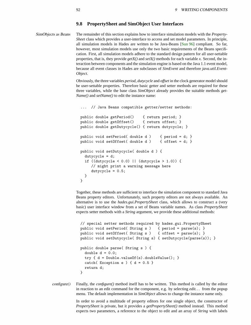
92 9 WRITING COMPONENTS
9.8 PropertySheet and SimObject User Interfaces
The remainder of this section explains how to interface simulation models with theProperty-SimObjects as BeansSheetclass which provides a user-interface to access and set model parameters. In principle,all simulation models in Hades are written to be Java-Beans [Sun 96] compliant. So far,however, most simulation models use only the two basic requirements of the Beans specifi-cation. First, all simulation models adhere to the standard design pattern for all user-settableproperties, that is, they providegetX()andsetX()methods for each variablex. Second, the in-teraction between components and the simulation engine is based on the Java 1.1 event model,because all event classes in Hades are subclasses ofSimEventand thereforejava.util.Event-Object.
Obviously, the three variablesperiod, dutycycleandoffsetin the clock generator model shouldbe user-settable properties. Therefore basic getter and setter methods are required for thesethree variables, while the base classSimObjectalready provides the suitable methodsget-Name()andsetName()to edit the instance name:
... // Java Beans compatible getter/setter methods:
public double getPeriod() { return period; }public double getOffset() { return offset; }public double getDutycycle() { return dutycycle; }
public void setPeriod( double d ) { period = d; }public void setOffset( double d ) { offset = d; }
public void setDutycycle( double d ) {dutycycle = d;if ((dutycycle < 0.0) || (dutycycle > 1.0)) {
// might print a warning message heredutycycle = 0.5;
}}
Together, these methods are sufficient to interface the simulation component to standard JavaBeans property editors. Unfortunately, such property editors are not always available. Analternative is to use thehades.gui.PropertySheetclass, which allows to construct a (verybasic) user interface window from a set of Beans variable names. As classPropertySheetexpects setter methods with aStringargument, we provide these additional methods:
// special setter methods required by hades.gui.PropertySheetpublic void setPeriod( String s ) { period = parse(s); }public void setOffset( String s ) { offset = parse(s); }public void setDutycycle( String s) { setDutycycle(parse(s)); }
public double parse( String s ) {double d = 0.0;try { d = Double.valueOf(s).doubleValue(); }catch( Exception e ) { d = 0.5 }return d;
}
Finally, theconfigure()method itself has to be written. This method is called by the editorconfigure()in reaction to an edit command for the component, e.g. by selectingedit. . . from the popupmenu. The default implementation inSimObjectallows to change the instance name only.
In order to avoid a multitude of property editors for one single object, the constructor ofPropertySheetis private, but it provides agetPropertySheet()method instead. This methodexpects two parameters, a reference to the object to edit and an array ofString with labels
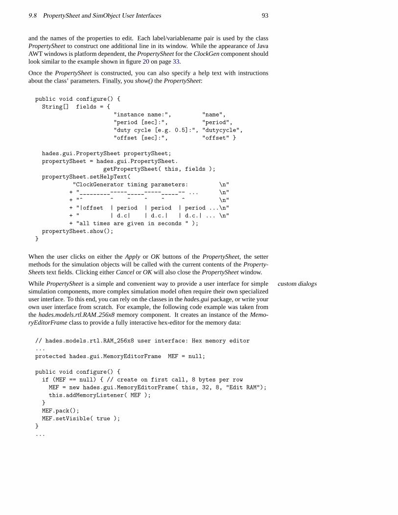
9.8 PropertySheet and SimObject User Interfaces 93
and the names of the properties to edit. Each label/variablename pair is used by the classPropertySheetto construct one additional line in its window. While the appearance of JavaAWT windows is platform dependent, thePropertySheetfor theClockGencomponent shouldlook similar to the example shown in figure20on page33.
Once thePropertySheetis constructed, you can also specify a help text with instructionsabout the class’ parameters. Finally, youshow()thePropertySheet:
public void configure() {String[] fields = {
"instance name:", "name","period [sec]:", "period","duty cycle [e.g. 0.5]:", "dutycycle","offset [sec]:", "offset" }
hades.gui.PropertySheet propertySheet;propertySheet = hades.gui.PropertySheet.
getPropertySheet( this, fields );propertySheet.setHelpText(
"ClockGenerator timing parameters: \n"+ "_________-----_____-----_____-- ... \n"+ "^ ^ ^ ^ ^ ^ \n"+ "|offset | period | period | period ...\n"+ " | d.c| | d.c.| | d.c.| ... \n"+ "all times are given in seconds " );
propertySheet.show();}
When the user clicks on either theApply or OK buttons of thePropertySheet, the settermethods for the simulation objects will be called with the current contents of theProperty-Sheets text fields. Clicking eitherCancelor OK will also close thePropertySheetwindow.
While PropertySheetis a simple and convenient way to provide a user interface for simplecustom dialogssimulation components, more complex simulation model often require their own specializeduser interface. To this end, you can rely on the classes in thehades.guipackage, or write yourown user interface from scratch. For example, the following code example was taken fromthe hades.models.rtl.RAM256x8memory component. It creates an instance of theMemo-ryEditorFrameclass to provide a fully interactive hex-editor for the memory data:
// hades.models.rtl.RAM_256x8 user interface: Hex memory editor...protected hades.gui.MemoryEditorFrame MEF = null;
public void configure() {if (MEF == null) { // create on first call, 8 bytes per rowMEF = new hades.gui.MemoryEditorFrame( this, 32, 8, "Edit RAM");this.addMemoryListener( MEF );
}MEF.pack();MEF.setVisible( true );
}...
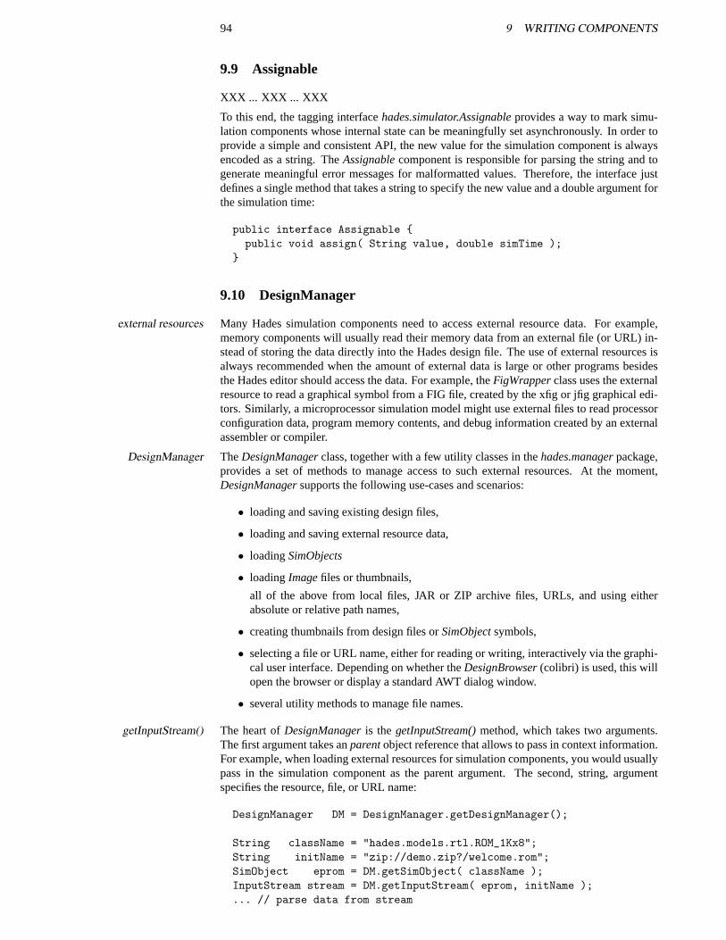
94 9 WRITING COMPONENTS
9.9 Assignable
XXX ... XXX ... XXX
To this end, the tagging interfacehades.simulator.Assignableprovides a way to mark simu-lation components whose internal state can be meaningfully set asynchronously. In order toprovide a simple and consistent API, the new value for the simulation component is alwaysencoded as a string. TheAssignablecomponent is responsible for parsing the string and togenerate meaningful error messages for malformatted values. Therefore, the interface justdefines a single method that takes a string to specify the new value and a double argument forthe simulation time:
public interface Assignable {public void assign( String value, double simTime );
}
9.10 DesignManager
Many Hades simulation components need to access external resource data. For example,external resourcesmemory components will usually read their memory data from an external file (or URL) in-stead of storing the data directly into the Hades design file. The use of external resources isalways recommended when the amount of external data is large or other programs besidesthe Hades editor should access the data. For example, theFigWrapperclass uses the externalresource to read a graphical symbol from a FIG file, created by the xfig or jfig graphical edi-tors. Similarly, a microprocessor simulation model might use external files to read processorconfiguration data, program memory contents, and debug information created by an externalassembler or compiler.
TheDesignManagerclass, together with a few utility classes in thehades.managerpackage,DesignManagerprovides a set of methods to manage access to such external resources. At the moment,DesignManagersupports the following use-cases and scenarios:
• loading and saving existing design files,
• loading and saving external resource data,
• loadingSimObjects
• loadingImagefiles or thumbnails,
all of the above from local files, JAR or ZIP archive files, URLs, and using eitherabsolute or relative path names,
• creating thumbnails from design files orSimObjectsymbols,
• selecting a file or URL name, either for reading or writing, interactively via the graphi-cal user interface. Depending on whether theDesignBrowser(colibri) is used, this willopen the browser or display a standard AWT dialog window.
• several utility methods to manage file names.
The heart ofDesignManageris thegetInputStream()method, which takes two arguments.getInputStream()The first argument takes anparentobject reference that allows to pass in context information.For example, when loading external resources for simulation components, you would usuallypass in the simulation component as the parent argument. The second, string, argumentspecifies the resource, file, or URL name:
DesignManager DM = DesignManager.getDesignManager();
String className = "hades.models.rtl.ROM_1Kx8";String initName = "zip://demo.zip?/welcome.rom";SimObject eprom = DM.getSimObject( className );InputStream stream = DM.getInputStream( eprom, initName );... // parse data from stream
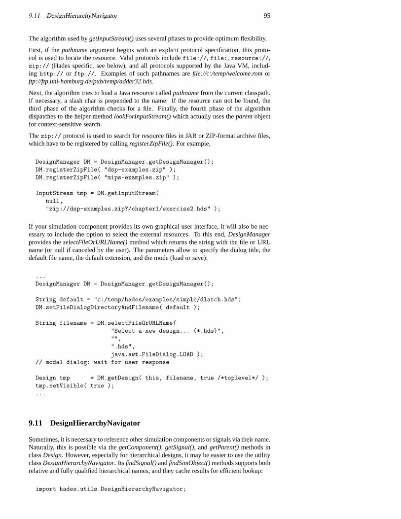
9.11 DesignHierarchyNavigator 95
The algorithm used bygetInputStream()uses several phases to provide optimum flexibility.
First, if the pathnameargument begins with an explicit protocol specification, this proto-col is used to locate the resource. Valid protocols includefile://, file:, resource://,zip:// (Hades specific, see below), and all protocols supported by the Java VM, includ-ing http:// or ftp://. Examples of such pathnames arefile://c:/temp/welcome.romorftp://ftp.uni-hamburg.de/pub/temp/adder32.hds.
Next, the algorithm tries to load a Java resource calledpathnamefrom the current classpath.If necessary, a slash char is prepended to the name. If the resource can not be found, thethird phase of the algorithm checks for a file. Finally, the fourth phase of the algorithmdispatches to the helper methodlookForInputStream()which actually uses theparentobjectfor context-sensitive search.
Thezip:// protocol is used to search for resource files in JAR or ZIP-format archive files,which have to be registered by callingregisterZipFile(). For example,
DesignManager DM = DesignManager.getDesignManager();DM.registerZipFile( "dsp-examples.zip" );DM.registerZipFile( "mips-examples.zip" );
InputStream tmp = DM.getInputStream(null,"zip://dsp-examples.zip?/chapter1/exercise2.hds" );
If your simulation component provides its own graphical user interface, it will also be nec-essary to include the option to select the external resources. To this end,DesignManagerprovides theselectFileOrURLName()method which returns the string with the file or URLname (or null if canceled by the user). The parameters allow to specify the dialog title, thedefault file name, the default extension, and the mode (load or save):
...DesignManager DM = DesignManager.getDesignManager();
String default = "c:/temp/hades/examples/simple/dlatch.hds";DM.setFileDialogDirectoryAndFilename( default );
String filename = DM.selectFileOrURLName("Select a new design... (*.hds)","",".hds",java.awt.FileDialog.LOAD );
// modal dialog: wait for user response
Design tmp = DM.getDesign( this, filename, true /*toplevel*/ );tmp.setVisible( true );...
9.11 DesignHierarchyNavigator
Sometimes, it is necessary to reference other simulation components or signals via their name.Naturally, this is possible via thegetComponent(), getSignal(), andgetParent()methods inclassDesign. However, especially for hierarchical designs, it may be easier to use the utilityclassDesignHierarchyNavigator. ItsfindSignal()andfindSimObject()methods supports bothrelative and fully qualified hierarchical names, and they cache results for efficient lookup:
import hades.utils.DesignHierarchyNavigator;

96 9 WRITING COMPONENTS
...DesignHierachyNavigator navigator
= new DesignHierarchyNavigator( design );
Signal signal = navigator.findSignal( "/uut/adder8/cla4/cout" );SimObject obj = navigator.findSimObject( "clockgen" );...
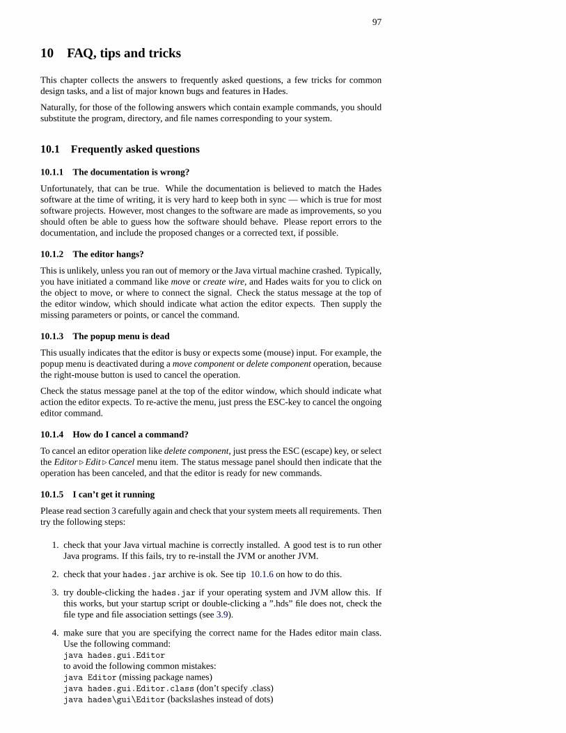
97
10 FAQ, tips and tricks
This chapter collects the answers to frequently asked questions, a few tricks for commondesign tasks, and a list of major known bugs and features in Hades.
Naturally, for those of the following answers which contain example commands, you shouldsubstitute the program, directory, and file names corresponding to your system.
10.1 Frequently asked questions
10.1.1 The documentation is wrong?
Unfortunately, that can be true. While the documentation is believed to match the Hadessoftware at the time of writing, it is very hard to keep both in sync — which is true for mostsoftware projects. However, most changes to the software are made as improvements, so youshould often be able to guess how the software should behave. Please report errors to thedocumentation, and include the proposed changes or a corrected text, if possible.
10.1.2 The editor hangs?
This is unlikely, unless you ran out of memory or the Java virtual machine crashed. Typically,you have initiated a command likemoveor create wire, and Hades waits for you to click onthe object to move, or where to connect the signal. Check the status message at the top ofthe editor window, which should indicate what action the editor expects. Then supply themissing parameters or points, or cancel the command.
10.1.3 The popup menu is dead
This usually indicates that the editor is busy or expects some (mouse) input. For example, thepopup menu is deactivated during amove componentor delete componentoperation, becausethe right-mouse button is used to cancel the operation.
Check the status message panel at the top of the editor window, which should indicate whataction the editor expects. To re-active the menu, just press the ESC-key to cancel the ongoingeditor command.
10.1.4 How do I cancel a command?
To cancel an editor operation likedelete component, just press the ESC (escape) key, or selecttheEditor. Edit. Cancelmenu item. The status message panel should then indicate that theoperation has been canceled, and that the editor is ready for new commands.
10.1.5 I can’t get it running
Please read section3 carefully again and check that your system meets all requirements. Thentry the following steps:
1. check that your Java virtual machine is correctly installed. A good test is to run otherJava programs. If this fails, try to re-install the JVM or another JVM.
2. check that yourhades.jar archive is ok. See tip10.1.6on how to do this.
3. try double-clicking thehades.jar if your operating system and JVM allow this. Ifthis works, but your startup script or double-clicking a ”.hds” file does not, check thefile type and file association settings (see3.9).
4. make sure that you are specifying the correct name for the Hades editor main class.Use the following command:java hades.gui.Editorto avoid the following common mistakes:java Editor (missing package names)java hades.gui.Editor.class (don’t specify .class)java hades\gui\Editor (backslashes instead of dots)
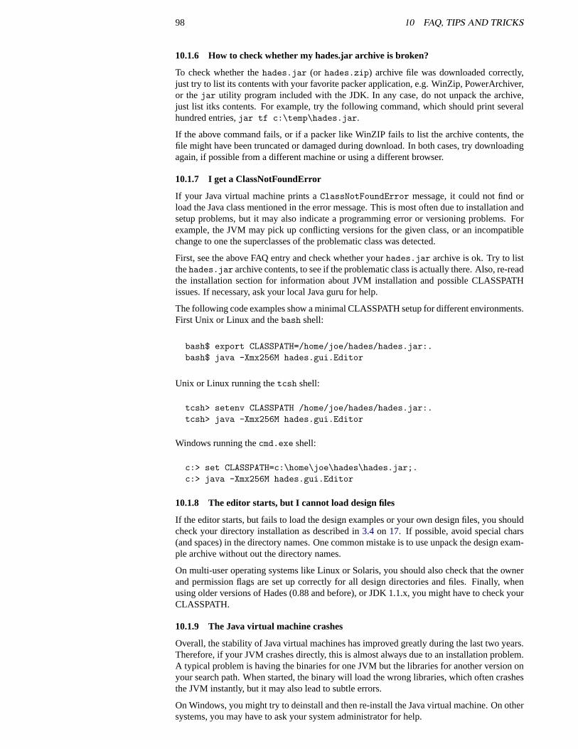
98 10 FAQ, TIPS AND TRICKS
10.1.6 How to check whether my hades.jar archive is broken?
To check whether thehades.jar (or hades.zip) archive file was downloaded correctly,just try to list its contents with your favorite packer application, e.g. WinZip, PowerArchiver,or thejar utility program included with the JDK. In any case, do not unpack the archive,just list itks contents. For example, try the following command, which should print severalhundred entries,jar tf c:\temp\hades.jar.
If the above command fails, or if a packer like WinZIP fails to list the archive contents, thefile might have been truncated or damaged during download. In both cases, try downloadingagain, if possible from a different machine or using a different browser.
10.1.7 I get a ClassNotFoundError
If your Java virtual machine prints aClassNotFoundError message, it could not find orload the Java class mentioned in the error message. This is most often due to installation andsetup problems, but it may also indicate a programming error or versioning problems. Forexample, the JVM may pick up conflicting versions for the given class, or an incompatiblechange to one the superclasses of the problematic class was detected.
First, see the above FAQ entry and check whether yourhades.jar archive is ok. Try to listthehades.jar archive contents, to see if the problematic class is actually there. Also, re-readthe installation section for information about JVM installation and possible CLASSPATHissues. If necessary, ask your local Java guru for help.
The following code examples show a minimal CLASSPATH setup for different environments.First Unix or Linux and thebash shell:
bash$ export CLASSPATH=/home/joe/hades/hades.jar:.bash$ java -Xmx256M hades.gui.Editor
Unix or Linux running thetcsh shell:
tcsh> setenv CLASSPATH /home/joe/hades/hades.jar:.tcsh> java -Xmx256M hades.gui.Editor
Windows running thecmd.exe shell:
c:> set CLASSPATH=c:\home\joe\hades\hades.jar;.c:> java -Xmx256M hades.gui.Editor
10.1.8 The editor starts, but I cannot load design files
If the editor starts, but fails to load the design examples or your own design files, you shouldcheck your directory installation as described in3.4 on 17. If possible, avoid special chars(and spaces) in the directory names. One common mistake is to use unpack the design exam-ple archive without out the directory names.
On multi-user operating systems like Linux or Solaris, you should also check that the ownerand permission flags are set up correctly for all design directories and files. Finally, whenusing older versions of Hades (0.88 and before), or JDK 1.1.x, you might have to check yourCLASSPATH.
10.1.9 The Java virtual machine crashes
Overall, the stability of Java virtual machines has improved greatly during the last two years.Therefore, if your JVM crashes directly, this is almost always due to an installation problem.A typical problem is having the binaries for one JVM but the libraries for another version onyour search path. When started, the binary will load the wrong libraries, which often crashesthe JVM instantly, but it may also lead to subtle errors.
On Windows, you might try to deinstall and then re-install the Java virtual machine. On othersystems, you may have to ask your system administrator for help.
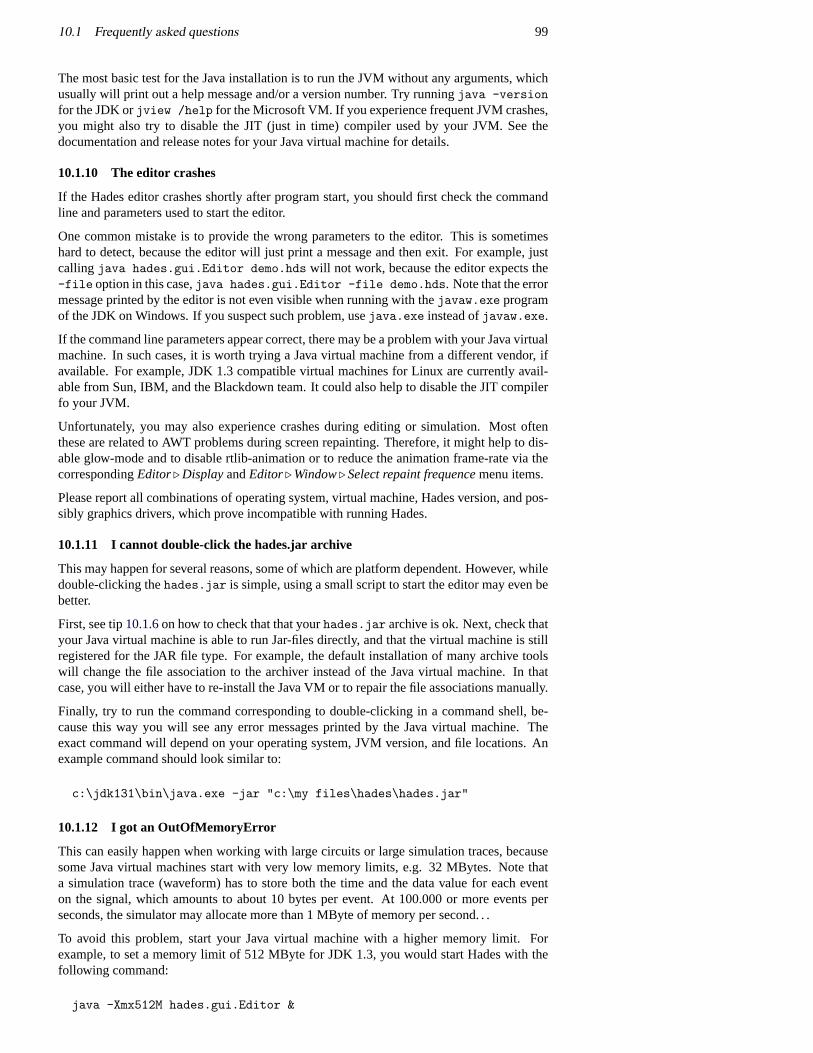
10.1 Frequently asked questions 99
The most basic test for the Java installation is to run the JVM without any arguments, whichusually will print out a help message and/or a version number. Try runningjava -versionfor the JDK orjview /help for the Microsoft VM. If you experience frequent JVM crashes,you might also try to disable the JIT (just in time) compiler used by your JVM. See thedocumentation and release notes for your Java virtual machine for details.
10.1.10 The editor crashes
If the Hades editor crashes shortly after program start, you should first check the commandline and parameters used to start the editor.
One common mistake is to provide the wrong parameters to the editor. This is sometimeshard to detect, because the editor will just print a message and then exit. For example, justcalling java hades.gui.Editor demo.hds will not work, because the editor expects the-file option in this case,java hades.gui.Editor -file demo.hds. Note that the errormessage printed by the editor is not even visible when running with thejavaw.exe programof the JDK on Windows. If you suspect such problem, usejava.exe instead ofjavaw.exe.
If the command line parameters appear correct, there may be a problem with your Java virtualmachine. In such cases, it is worth trying a Java virtual machine from a different vendor, ifavailable. For example, JDK 1.3 compatible virtual machines for Linux are currently avail-able from Sun, IBM, and the Blackdown team. It could also help to disable the JIT compilerfo your JVM.
Unfortunately, you may also experience crashes during editing or simulation. Most oftenthese are related to AWT problems during screen repainting. Therefore, it might help to dis-able glow-mode and to disable rtlib-animation or to reduce the animation frame-rate via thecorrespondingEditor. DisplayandEditor. Window. Select repaint frequencemenu items.
Please report all combinations of operating system, virtual machine, Hades version, and pos-sibly graphics drivers, which prove incompatible with running Hades.
10.1.11 I cannot double-click the hades.jar archive
This may happen for several reasons, some of which are platform dependent. However, whiledouble-clicking thehades.jar is simple, using a small script to start the editor may even bebetter.
First, see tip10.1.6on how to check that that yourhades.jar archive is ok. Next, check thatyour Java virtual machine is able to run Jar-files directly, and that the virtual machine is stillregistered for the JAR file type. For example, the default installation of many archive toolswill change the file association to the archiver instead of the Java virtual machine. In thatcase, you will either have to re-install the Java VM or to repair the file associations manually.
Finally, try to run the command corresponding to double-clicking in a command shell, be-cause this way you will see any error messages printed by the Java virtual machine. Theexact command will depend on your operating system, JVM version, and file locations. Anexample command should look similar to:
c:\jdk131\bin\java.exe -jar "c:\my files\hades\hades.jar"
10.1.12 I got an OutOfMemoryError
This can easily happen when working with large circuits or large simulation traces, becausesome Java virtual machines start with very low memory limits, e.g. 32 MBytes. Note thata simulation trace (waveform) has to store both the time and the data value for each eventon the signal, which amounts to about 10 bytes per event. At 100.000 or more events perseconds, the simulator may allocate more than 1 MByte of memory per second. . .
To avoid this problem, start your Java virtual machine with a higher memory limit. Forexample, to set a memory limit of 512 MByte for JDK 1.3, you would start Hades with thefollowing command:
java -Xmx512M hades.gui.Editor &
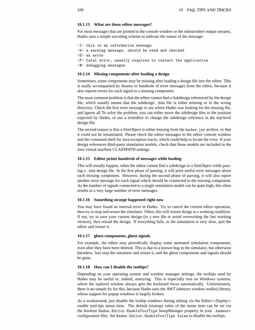
100 10 FAQ, TIPS AND TRICKS
10.1.13 What are those editor messages?
For most messages that are printed to the console window or the stdout/stderr output streams,Hades uses a simple encoding scheme to indicate the nature of the message:
-I- this is an information message-W- a warning message, should be read and checked-E- an error-F- fatal error, usually requires to restart the application-#- debugging messages
10.1.14 Missing components after loading a design
Sometimes, some components may be missing after loading a design file into the editor. Thisis usally accompanied by dozens or hundreds of error messages from the editor, because italso reports errors for each signal to a missing component.
The most common problem is that the editor cannot find a Subdesign referenced by the designfile, which usually means that the subdesign.hds file is either missing or in the wrongdirectory. Check the first error message to see where Hades was looking for the missing file,and ignore all To solve the problem, you can either move the subdesign files to the positionexpected by Hades, or use a texteditor to change the subdesign reference in the top-leveldesign file.
The second reason is that a SimObject is either missing from thehades.jar archive, or thatit could not be instantiated. Please check the editor messages in the editor console windowand the command shell for Java exception traces, which could help to locate the error. If yourdesign references third-party simulation models, check that those models are included in theJava virtual machine CLASSPATH settings.
10.1.15 Editor prints hundreds of messages while loading
This will usually happen, when the editor cannot find a subdesign or a SimObject while pars-ing a.hds design file. In the first phase of parsing, it will print useful error messages abouteach missing component. However, during the second phase of parsing, it will also reportanother error message for each signal which should be connected to the missing component.As the number of signals connected to a single simulation model can be quite high, this oftenresults in a very large number of error messages.
10.1.16 Something strange happened right now
You may have found an internal error in Hades. Try to cancel the current editor operation,then try to stop and restart the simulator. Often, this will restore things to a working condition.If not, try to save your current design (to a new file to avoid overwriting the last workingversion), then reload the design. If everything fails, or the simulation is very slow, quit theeditor and restart it.
10.1.17 ghost components, ghost signals
For example, the editor may periodically display some animated simulation components,even after they have been deleted. This is due to a known bug in the simulator, but otherwiseharmless. Just stop the simulator and restart it, and the ghost components and signals shouldbe gone.
10.1.18 How can I disable the tooltips?
Depending on your operating system and window manager settings, the tooltips used byHades may be useful or, indeed, annoying. This is especially true on Windows systems,where the toplevel window always gets the keyboard focus automatically. Unfortunately,there is no simple fix for this, because Hades uses the AWT (abstract window toolkit) library,whose support for popup windows is largely broken.
As a workaround, just disable the tooltip windows during editing via theEditor. Display.enable tool-tipsmenu item. The default (startup) value of the menu item can be set viathe booleanHades.Editor.EnableToolTips SetupManager property in your.hadesrcconfiguration files. SetHades.Editor.EnableToolTips false to disable the tooltips.
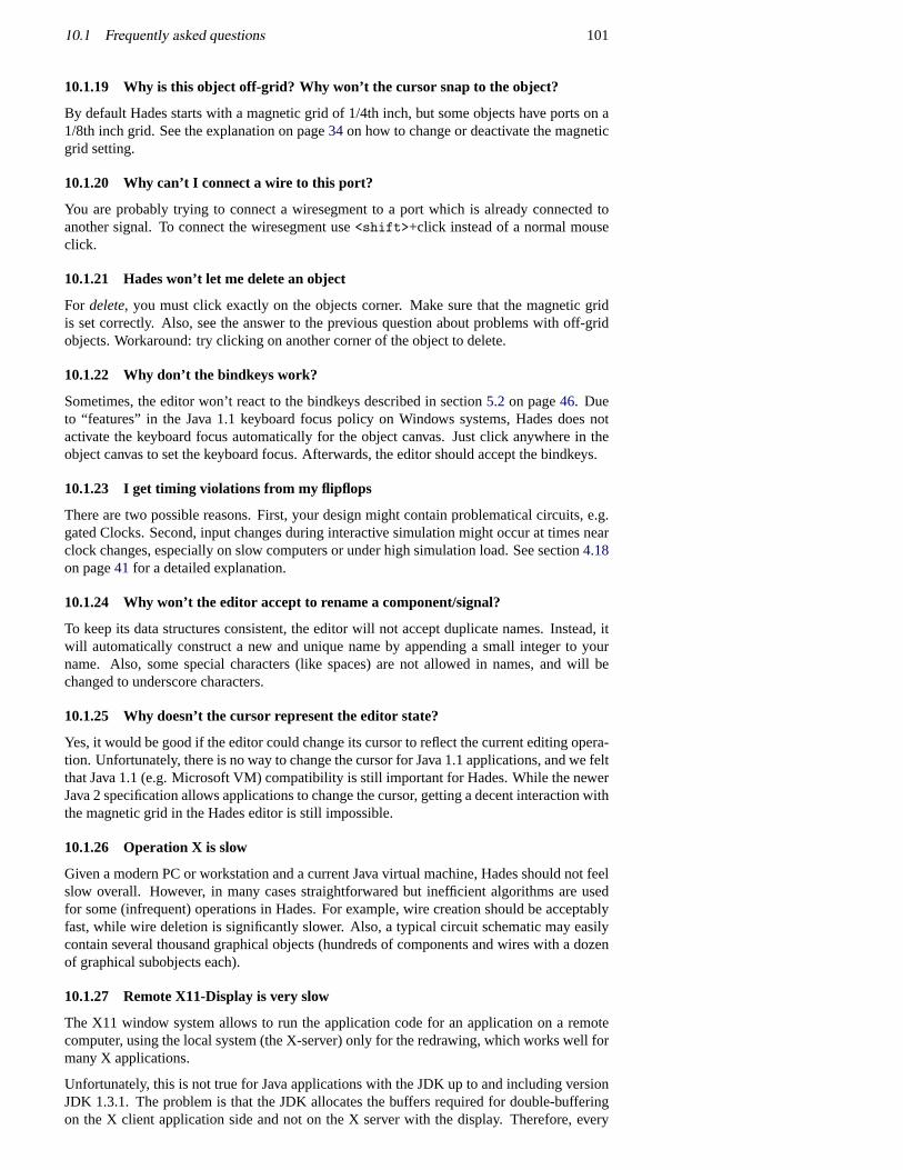
10.1 Frequently asked questions 101
10.1.19 Why is this object off-grid? Why won’t the cursor snap to the object?
By default Hades starts with a magnetic grid of 1/4th inch, but some objects have ports on a1/8th inch grid. See the explanation on page34 on how to change or deactivate the magneticgrid setting.
10.1.20 Why can’t I connect a wire to this port?
You are probably trying to connect a wiresegment to a port which is already connected toanother signal. To connect the wiresegment use<shift>+click instead of a normal mouseclick.
10.1.21 Hades won’t let me delete an object
For delete, you must click exactly on the objects corner. Make sure that the magnetic gridis set correctly. Also, see the answer to the previous question about problems with off-gridobjects. Workaround: try clicking on another corner of the object to delete.
10.1.22 Why don’t the bindkeys work?
Sometimes, the editor won’t react to the bindkeys described in section5.2 on page46. Dueto “features” in the Java 1.1 keyboard focus policy on Windows systems, Hades does notactivate the keyboard focus automatically for the object canvas. Just click anywhere in theobject canvas to set the keyboard focus. Afterwards, the editor should accept the bindkeys.
10.1.23 I get timing violations from my flipflops
There are two possible reasons. First, your design might contain problematical circuits, e.g.gated Clocks. Second, input changes during interactive simulation might occur at times nearclock changes, especially on slow computers or under high simulation load. See section4.18on page41 for a detailed explanation.
10.1.24 Why won’t the editor accept to rename a component/signal?
To keep its data structures consistent, the editor will not accept duplicate names. Instead, itwill automatically construct a new and unique name by appending a small integer to yourname. Also, some special characters (like spaces) are not allowed in names, and will bechanged to underscore characters.
10.1.25 Why doesn’t the cursor represent the editor state?
Yes, it would be good if the editor could change its cursor to reflect the current editing opera-tion. Unfortunately, there is no way to change the cursor for Java 1.1 applications, and we feltthat Java 1.1 (e.g. Microsoft VM) compatibility is still important for Hades. While the newerJava 2 specification allows applications to change the cursor, getting a decent interaction withthe magnetic grid in the Hades editor is still impossible.
10.1.26 Operation X is slow
Given a modern PC or workstation and a current Java virtual machine, Hades should not feelslow overall. However, in many cases straightforwared but inefficient algorithms are usedfor some (infrequent) operations in Hades. For example, wire creation should be acceptablyfast, while wire deletion is significantly slower. Also, a typical circuit schematic may easilycontain several thousand graphical objects (hundreds of components and wires with a dozenof graphical subobjects each).
10.1.27 Remote X11-Display is very slow
The X11 window system allows to run the application code for an application on a remotecomputer, using the local system (the X-server) only for the redrawing, which works well formany X applications.
Unfortunately, this is not true for Java applications with the JDK up to and including versionJDK 1.3.1. The problem is that the JDK allocates the buffers required for double-bufferingon the X client application side and not on the X server with the display. Therefore, every
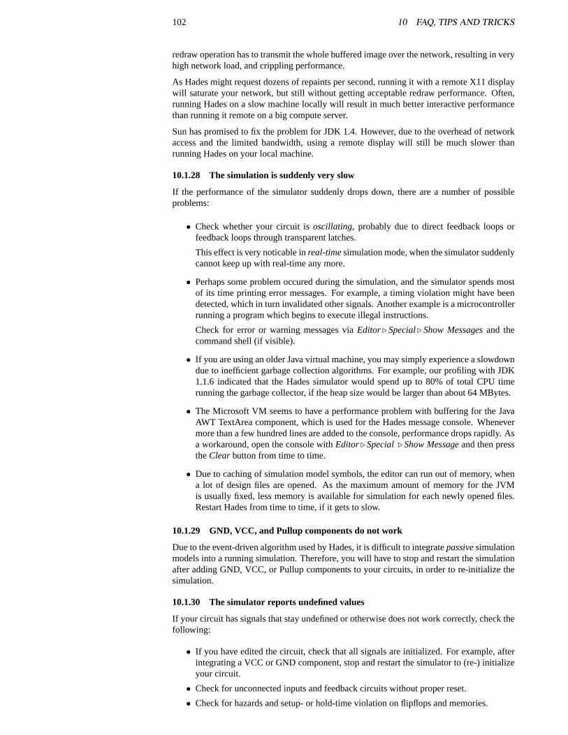
102 10 FAQ, TIPS AND TRICKS
redraw operation has to transmit the whole buffered image over the network, resulting in veryhigh network load, and crippling performance.
As Hades might request dozens of repaints per second, running it with a remote X11 displaywill saturate your network, but still without getting acceptable redraw performance. Often,running Hades on a slow machine locally will result in much better interactive performancethan running it remote on a big compute server.
Sun has promised to fix the problem for JDK 1.4. However, due to the overhead of networkaccess and the limited bandwidth, using a remote display will still be much slower thanrunning Hades on your local machine.
10.1.28 The simulation is suddenly very slow
If the performance of the simulator suddenly drops down, there are a number of possibleproblems:
• Check whether your circuit isoscillating, probably due to direct feedback loops orfeedback loops through transparent latches.
This effect is very noticable inreal-timesimulation mode, when the simulator suddenlycannot keep up with real-time any more.
• Perhaps some problem occured during the simulation, and the simulator spends mostof its time printing error messages. For example, a timing violation might have beendetected, which in turn invalidated other signals. Another example is a microcontrollerrunning a program which begins to execute illegal instructions.
Check for error or warning messages viaEditor. Special. Show Messagesand thecommand shell (if visible).
• If you are using an older Java virtual machine, you may simply experience a slowdowndue to inefficient garbage collection algorithms. For example, our profiling with JDK1.1.6 indicated that the Hades simulator would spend up to 80% of total CPU timerunning the garbage collector, if the heap size would be larger than about 64 MBytes.
• The Microsoft VM seems to have a performance problem with buffering for the JavaAWT TextArea component, which is used for the Hades message console. Whenevermore than a few hundred lines are added to the console, performance drops rapidly. Asa workaround, open the console withEditor. Special. Show Messageand then presstheClearbutton from time to time.
• Due to caching of simulation model symbols, the editor can run out of memory, whena lot of design files are opened. As the maximum amount of memory for the JVMis usually fixed, less memory is available for simulation for each newly opened files.Restart Hades from time to time, if it gets to slow.
10.1.29 GND, VCC, and Pullup components do not work
Due to the event-driven algorithm used by Hades, it is difficult to integratepassivesimulationmodels into a running simulation. Therefore, you will have to stop and restart the simulationafter adding GND, VCC, or Pullup components to your circuits, in order to re-initialize thesimulation.
10.1.30 The simulator reports undefined values
If your circuit has signals that stay undefined or otherwise does not work correctly, check thefollowing:
• If you have edited the circuit, check that all signals are initialized. For example, afterintegrating a VCC or GND component, stop and restart the simulator to (re-) initializeyour circuit.
• Check for unconnected inputs and feedback circuits without proper reset.
• Check for hazards and setup- or hold-time violation on flipflops and memories.
10.2 Tips and tricks 103
• Check for undefined or short-circuit conditions on buses.
• Make sure that registers and memories are properly initialized via loading of initialmemory contents, or via expliciat initialization sequences.
• See section10.2.4for some tips on debugging.
10.1.31 How can I automatically restore editor settings?
First of all, try to set the corresponding values for the SetupManager properties in the.hadesrc configuration file. See sectionA for details.
If you want to customize other settings, you could use either a scripting language or write asmall initialization class in Java.
10.1.32 My waveforms get overwritten?
Currently, all data for waveforms is stored in memory. As the simulator may easily execute100.000 events per second, and the raw data for each event consists of a time value (8 bytes)and a data value (1 to 30 bytes), using waveforms may require more than one 1 MByte ofmemory per second.
While more memory is available, the waveforms will store all events. Once the availablememory is exhausted, the waveform classes will periodically overwrite the oldest data inorder to make room for the newer data. Due to the multithreaded nature of Java, even thisalgorithm can’t always prevent premature OutOfMemoryErrors.
If you want to preserve the older waveform data, you should run the simulation only for sometime, pause the simulation, and the save the waveform data to a file, before continuing withthe simulation.
10.1.33 How can I edit a SimObject symbol?
As Hades does not have a graphical symbol editor, you will have to write the symbol file foryour own simulation models with a text editor. See section9.3 on 80 for an examplanationand an example.
10.2 Tips and tricks
10.2.1 What other programs are in hades.jar? How to run them?
One of the advantages of object-oriented programming and the Java object model is thatevery class can be used as an application, if only it provides its ownmain() method. Notsurprisingly, many classes in Hades have their ownmain() and can be run as the main class.However, all classes are packed into thehades.jar archive file, which only provides a singlemain-class (namely,hades.gui.Editor).
To access and run the other classes insidehades.jar, you have to use a command shell tocall the Java virtual machine with the corresponding parameters. When called without furtherparameters, Most of the classes will print a short usage message.
Some of the useful classes insidehades.jar:
• jfig.gui.Editor theJFIG graphics editor.
• hades.models.pic.PicAssembler a command line assembler for the PIC 16family of microcontrollers which creates raw.rom or Intel HEX .hex files. The as-sembler accepts many MPASM assembler files directly of with only minor changes.
• hades.utils.NameMangler The tool used by Hades to encode Unicode charactersfor use in the.hds and.sym design and symbol files. Use the command line versionto encode or decode strings manually.
• hades.utils.vhdl.VHDLWriter A command line tool to convert Hades designfiles into a VHDL netlist, preserving the design hierarchy. Note that the convertercannot generate VHDL simulation models for most of the complex Hades simulationmodels. Currently, it only understands several gate-level models, including basic gates,complex gates, flipflops, and clock generator.

104 10 FAQ, TIPS AND TRICKS
10.2.2 User-settings in .hadesrc
See the description in section3.8 on how to customize the Hades editor and tools via the.hadesrc configuration files. AppendixA lists all configuration properties together withtheir default values.
10.2.3 How to enable or disable glow-mode for individual signals?
This is possible via theh bindkey in the editor. Move to cursor to a vertex of the signal inquestion, then press theh key to toggle glow-mode for that signal.
Naturally, you can also enable or disable glow-mode for each signal via explicit method callsto signal.setGlowMode(). See the examples in section8 on page65.
10.2.4 What can I do to debug my circuits?
• Activate glow-mode and interactive simulation to play with your circuit. Watch out forundefined signals (cyan and magenta colors).
• Add probes to all relevant signals and watch the signal traces in the waveform viewer.Check all signals which carryU or X values carefully. Also note that floating signals (Zvalue) are not a good idea. Consider adding pullup components to buses.
• Check the editor message console for all warning and error messages like flipflop tim-ing violations, missing memory initialization data files, or even simulator internal er-rors.
• SelectEditor. Special. Check designmenu item and read the messages in the consolewindow. The editor will report all unconnected (open) inputs, short-circuit outputs, etc.
• Usedesign for testmethods, like including extra reset inputs, extra status-outputs, orbuilt-in-selftest logic.
• Add measurement equipmentto strategic signals in your circuit. For example, try ahades.models.special.HazardTrigger or ahades.models.special.Counterto detect hazards or to count events on a signal.
• As a last resort, try to single-step the simulator through your circuit, and periodicallyuse the debug menu items likeEditor. Debug. Print eventlistto print internal sim-ulator state. This will not usually be necessary, except when debugging your ownJava-written simulation models.
10.2.5 I need a two-phase clock
To create a two-phase clock, just create twoClockGencomponents with the same clock pe-riod, the corresponding values for the duty cycle, and finally set the offset of one of the clocksto achieve the desired effect. For example, to create a non-overlapping 10 MHz clock withwaveforms “_1__” and “___1”, specify periods of 100 nsec., a dutycycle of 0.25 (25%) andoffsets of 0 nsec. and 50 nsec., respectively.
Naturally, you could also create a simple state machine subdesign to create multiple clocksfrom a single clock input.
10.2.6 How can I print my circuit schematics?
Just try theEditor. File . Print menu item. This will use the Java printing API to accessthe default printer(s) on your system. It will also change the zoom-factor of your currentschematic to A4 landscape paper and request a full redraw. If you select landscape paper inthe printer options dialog, you circuit should fit on the paper. Due to limitations in the Javaprinting API, however, the quality of the printing is not optimal. While texts and straightlines may be ok, arcs and spline objects are very jagged.
For high quality prints, you may prefer to export your schematics to FIG format, and then usethe fig2dev converter to produce high-quality Postscript, see below.
10.2 Tips and tricks 105
10.2.7 Printing problems
Currently, Hades uses the Java 1.1 API to access a printer, which results in suboptimalprint quality and is not very reliable. Also, there is a bug in the Hades graphics code,which prevents printing on some JDK 1.3 virtual machine, due to a conflict between Java2Denabled screen rendering and non-Java2D printer rendering. If you get exceptions whileprinting on a JDK 1.3 virtual machine, you might try to disable Java2D support via thejfig.allowJava2D SetupManager property in your.hadesrc file.
10.2.8 How can I export my circuit schematics via fig2dev?
As the Hades graphics editor is based on theJFIG graphics code, it is possible to exportcircuit schematics to the FIG file format, which can then also be edited with thexfig pro-gram available on many Unix/Linux systems, or thejfig.gui.Editor class included in thehades.jar archive.
Among the many programs that support the FIG format is thefig2dev format converter,which allows to convert FIG files into several image formats, HP GL, LATEX drawing com-mands, or high-quality Postscript. Iffig2dev is not installed on your system, you can down-load the sources fromftp.x.org. Contact your system vendor for pre-built binaries for Unixand Linux systems. A binary for Windows is available from theJFIG home page,tech-www.informatik.uni-hamburg.de /applets/jfig/.
In the editor, select theEditor. Export. Settings. . . menu item, which opens the exportoptions dialog. First, select whether you want color or black-and-white export (which mightbe better for printing on b/w printers). Next, fill in the remaining options and selectExportNow.
10.2.9 I cannot initialize my circuit
For well designed circuits with proper reset logic, there should be no problem. However,if you try to simulate legacy circuits you may experience difficulties in getting your cir-cuit to work. This is due to the simulation semantics and the industry standard nine-valuedstd_logic logic system used by Hades for gate-level simulations. All gates and flipflopswill start and stay in the specialU state, until all inputs are well-defined. Use switches or thePowerOnReset component to generate valid reset impulses after starting the simulation.
10.2.10 Simulation does not appear deterministic
This depends on your simulator settings and the simulation models used in your circuits.
When using the VHDL-based simulation kernel with its two-list algorithm (classhades.simulator.VhdlSimKernel), the simulation should be deterministic, as multiple instan-taneous events are deferred until the next delta-cycle. Events occuring in one delta-cycle areexecuted in random order, but this should not influence the final simulation state.
On the other hand, when using the simpler one-list simulation kernels, the simulation statedoes depend on the (random) ordering of events. For example, a basic NOR-flipflop willnever oscillate with this algorithm, because one gate will be evaluated first.
Note that some simulation models intentionally include random behaviour. For example, themetastable DFF flipflop will not generateU or X output values, when undefined input signalsor a timing violation are detected. Instead, the metastable flipflop will enter a random0 or 1state after a random delay.
10.2.11 I took a schematic from a book, but the circuit does not work
Unfortunately, this can happen, and there are several reasons for it. First of all, it is verydifficult to write a 100% error-free book, and it is even more difficult to get all the graphicsand figures correct. Therefore, the schematic you copied may simply have a few small errors.
Second, figures usually serve to illustrate a certain idea. This in turn leads to a compromisebetween a nice and easily understandable figure, or a very complex figure with all the gorydetails. Many authors, especially in textbooks, prefer the readable variant.
106 10 FAQ, TIPS AND TRICKS
Third, the function of a circuit often depends on technological constraints. For example,many legacy TTL circuits don’t include complex reset logic, because real TTL devices willbehave as expected by the designer. The same circuit in CMOS technology, however, mayenter undefined states or even a latch-up.
Fourth, while the simulation models are written to accurately model the behaviour of realdevices, there are certain differences. For example, theU andX states of thestd_logiclogic model are a simple means to model undefined logic states. However, circuits withoutproper reset logic will not be useable withstd_logic, unless explicit manual initializationsequences are used.
While this is not recommended, you might use the specialmetastableflipflops models fromthehades.models.flipflopspackage to model legacy circuits or other circuits with broken resetlogic. These simulation components,DffMetastableandLatchMetastablebehave differentlyfrom the usualDff or Latchmodels. They never generate the undefinedX or U output values,even when some inputs are undefined or a timing violation is detected. Instead, these flipflopsuse a random number to generate a random0 or 1 output in such conditions, and anotherrandom number is used to generate a random gate-delay (with may be up to 50 times longerthan the default gate-delay).
10.2.12 VHDL export
Netlist export of Hades designs to VHDL format is possible. This currently supports hi-erarchical designs and includes a name-mangling scheme which converts Hades signal andcomponent names to unique but still readable VHDL names. Try running thehades.utils.vhdl.VhdlWriter from thehades.jar archive and read the help message for the com-mand syntax and options.
TheVhdlWriter will write all entity declarations and defaultarchitecture blocks forall Hades schematics. It also includes support to write defaultarchitectures for gate-levelcomponents like simple and complex gates, several flipflops, clock generator and power-on-reset. Naturally, it can not translate arbitraty Java code to corresponding VHDL architectures.
So far, the export functions have only be tested with a few designs, and only with the Syn-opsys VSS simulator. Support for other simulators may require some changes in the namemangling.
10.3 Known bugs and features
10.3.1 How should I report bugs?
To report a bug send an email [email protected].
However, you might first check that the bug is actually a Hades bug instead of a knownproblem of your Java virtual machine. For example, several redraw problems are known forJava applications when running with JDK 1.2.x or JDK 1.3.x. See the release documentationfor your Java virtual machine for details.
Your mail should include your operating system and version, Java virtual machine and ver-sion, Hades version, CLASSPATH settings,.hadesrc property values, and the detailed errormessage, including stack traces. Usejava -version to print out your JDK version infor-mation. (For example, a useful message might include the following information: WindowsXP home, JDK 1.3.102, Hades 0.89b, no CLASSPATH set, default .hadesrc).
For multiple related errors, only report the first one. If possible, include all required.hdsdesign files and detailed instructions on how to reproduce the bug or (even better) a script filewhich demonstrates it.
10.3.2 Spurious objects displayed
When deleting a component like thehades.models.dcf77.Dcf77Clock generator, whichrepeatedly updates itself, the redraw thread may keep a reference to the delete component,which will the re-appear on the editor canvas.
To avoid this problem, stop and restart the simulator after deleting such component(s).

10.3 Known bugs and features 107
10.3.3 Repaint algorithm
The redraw algorithm used by Hades relies on a separate Thread for asynchronous repaints.However, due to the overhead of object synchronisation in Java, the editor does not fullysynchronize the simulation and the redrawing.
This means that the simulation continues to run even while a repaint is in progress. This maylead to inconsistent display for those objects, whose state changed during a repaint operation.
To get a static and fully consistent display, pause the simulation and wait for the next repaintoperation. It is also possible to request a full repaint via theEditor. Edit. Repaint allmenuitem.
10.3.4 Repaint bugs, DirectDraw
To improve performance, Hades uses a complex buffering scheme for screen redrawing. De-pending on the number of objects that require redrawing, either the whole offscreen buffer,parts of the offscreen buffer, or only the corresponding objects are drawn.
Unfortunately, this algorithm can trigger a known bug in JDK 1.3.x on Windows, where theJDK mixes Windows GDI and DirectDraw calls for redrawing. If you experience frequentredraw problems on a Windows system with JDK 1.3.x, try to call the Java virtual machinewith thejava -Dsun.java2d.noddraw hades.gui.Editor option. This will disable Di-rectDraw acceleration and should improve stability at the cost of performance.
On Linux and Solaris systems, the Java AWT toolkit is known for a lot of windowmanagerrelated problems. For example, windows may appear in the wrong size, with zero size, oreven outside the visible screen. The only known workaround in such cases is to try a differentcombination of Java virtual machine and window manager.
To repaint the whole editor user interface, select theEditor. Edit. Repaint allmenu item, orpress the CNTL-A bindkey on the main editor canvas.
10.3.5 How to get rid of an unconnected signal?
When opening a design file, the editor will check the design and detect several kinds of errors,including signals which are not connected to any simulation components. Unfortunately, suchsignals also don’t usually have wire segments, and can therefore not be selected or deletedvia the graphical editor. Currently, the only way to get rid of such unconnected signal is toedit the.hds design file with a text editor.
10.3.6 The ’run for’ simulator command may deadlock
The current version ofhades.simulator.VhdlSimKernel has a bug, which stops the sim-ulator after executing arun for simulator command instead of pausing it. This means that thesimulation cannot be continued.
Workaround: use therun command or specify a larger interval for therun for command.

108 10 FAQ, TIPS AND TRICKS
REFERENCES 109
References
[Cadence 97]Design Framework II 4.41 User Manual, Cadence Design Systems, Inc., SanJose, CA, USA, 1997
[DIGSIM] X.Y.Z. DIGSIM
[Gillespie & Lazzaro 96]D. Gillespie and J. Lazzaro,DigLOG and AnaLOG, Caltech VLSICAD Tools, California Institute of Technology, 1996ftp://ftp.pcmp.caltech.edu/pub/chipmunk/
[IEEE-87] IEEE Standard VHDL Hardware Description Language Reference Manual,IEEE Std 1076-1987, 1988
[IEEE-93a] IEEE Standard VHDL Hardware Description Language Reference Manual,IEEE Std 11xx-1993, 1993
[IEEE 93b] IEEE Standard Multivalue Logic System for VHDL Model Interoperability,Standard IEEE 1164-1993, 1993
[Jython] The Jython language homepage,www.jython.org
[Hendrich 97] N. Hendrich,HADES — A Java-based visual simulation environment, Fach-bereich Informatik, Universitat Hamburg, 1997
[Khoral 97] KHOROS 2.2, Khoral Research Inc., Albuquerque, New Mexico, US, 1997
[CACI 97] CACI, SIMGRAPHICS-II User’s Manual, CACI Products Company, La Jolla,CA, 1997
[Sun 95] The Java Whitepaper, Sun Microsystems, Mountain View, CA., 1995
[Sun 96] Java Beans Specification, version 1.0, Sun Microsystems, Mountain View, CA.,1996http://java.sun.com/beans
[Sun 97] Sun 100% pure Java initiative, Sun Microsystems, Mountain View, CA., 1997http://java.sun.com/purejava/
[Synopsys 97]Synopsys VSS 3.5a user manual, Synopsys Inc., Mountain View, CA, 1997
[xfig 3.2] Supoj Sutanthavibul, Paul King, Brian Smith,XFIG — Facility for InteractiveGeneration of figures under X11, Lawrence Berkeley Laboratory, CA, 1996
[Hennessy & Patterson]J.L. Hennessay and D.A. Patterson, Computer architecture, thehardware/software-interface, Morgan-Kaufmann, 199X
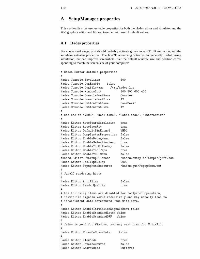
110 A SETUPMANAGER PROPERTIES
A SetupManager properties
This section lists the user-settable properties for both the Hades editor and simulator and theJFIG graphics editor and library, together with useful default values.
A.1 Hades properties
For educational usage, you should probably activate glow-mode, RTLIB animation, and thesimulator autostart properties. The Java2D antialising option is not generally useful duringsimulation, but can improve screenshots. Set the default window size and position corre-sponding to match the screen size of your computer:
# Hades Editor default properties#Hades.Console.SaveLines 600Hades.Console.LogEnable falseHades.Console.LogfileName /tmp/hades.logHades.Console.WindowInit 300 300 600 400Hades.Console.ConsoleFontName CourierHades.Console.ConsoleFontSize 12Hades.Console.ButtonFontName SansSerifHades.Console.ButtonFontSize 12## use one of "VHDL", "Real time", "Batch mode", "Interactive"#Hades.Editor.AutoStartSimulation trueHades.Editor.AutoZoomFit trueHades.Editor.DefaultSimKernel VHDLHades.Editor.DumpSystemProperties falseHades.Editor.EnableDebugMenu falseHades.Editor.EnableSelectionMenu trueHades.Editor.EnableTipOfTheDay falseHades.Editor.EnableToolTips trueHades.Editor.EnableVHDLMenu false#Hades.Editor.StartupFilename /hades/examples/simple/jkff.hdsHades.Editor.ToolTipsDelay 2000Hades.Editor.PopupMenuResource /hades/gui/PopupMenu.txt## Java2D rendering hints#Hades.Editor.AntiAlias falseHades.Editor.RenderQuality true## the following items are disabled for foolproof operation;# initialize signals works recursively and may usually lead to# inconsistent data structures: use with care.#Hades.Editor.EnableInitializeSignalsMenu falseHades.Editor.EnableStandardLatch falseHades.Editor.EnableStandardDFF false## false is good for Windows, you may want true for Unix/X11:#Hades.Editor.FocusOnMouseEnter false#Hades.Editor.GlowMode trueHades.Editor.InverseCanvas falseHades.Editor.RedrawMode Buffered
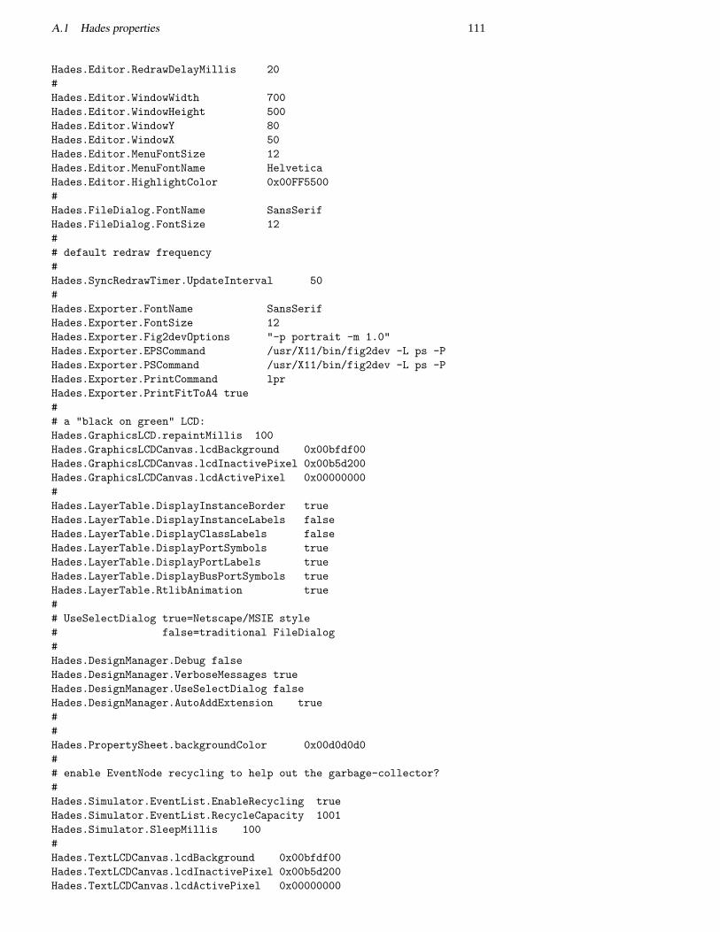
A.1 Hades properties 111
Hades.Editor.RedrawDelayMillis 20#Hades.Editor.WindowWidth 700Hades.Editor.WindowHeight 500Hades.Editor.WindowY 80Hades.Editor.WindowX 50Hades.Editor.MenuFontSize 12Hades.Editor.MenuFontName HelveticaHades.Editor.HighlightColor 0x00FF5500#Hades.FileDialog.FontName SansSerifHades.FileDialog.FontSize 12## default redraw frequency#Hades.SyncRedrawTimer.UpdateInterval 50#Hades.Exporter.FontName SansSerifHades.Exporter.FontSize 12Hades.Exporter.Fig2devOptions "-p portrait -m 1.0"Hades.Exporter.EPSCommand /usr/X11/bin/fig2dev -L ps -PHades.Exporter.PSCommand /usr/X11/bin/fig2dev -L ps -PHades.Exporter.PrintCommand lprHades.Exporter.PrintFitToA4 true## a "black on green" LCD:Hades.GraphicsLCD.repaintMillis 100Hades.GraphicsLCDCanvas.lcdBackground 0x00bfdf00Hades.GraphicsLCDCanvas.lcdInactivePixel 0x00b5d200Hades.GraphicsLCDCanvas.lcdActivePixel 0x00000000#Hades.LayerTable.DisplayInstanceBorder trueHades.LayerTable.DisplayInstanceLabels falseHades.LayerTable.DisplayClassLabels falseHades.LayerTable.DisplayPortSymbols trueHades.LayerTable.DisplayPortLabels trueHades.LayerTable.DisplayBusPortSymbols trueHades.LayerTable.RtlibAnimation true## UseSelectDialog true=Netscape/MSIE style# false=traditional FileDialog#Hades.DesignManager.Debug falseHades.DesignManager.VerboseMessages trueHades.DesignManager.UseSelectDialog falseHades.DesignManager.AutoAddExtension true##Hades.PropertySheet.backgroundColor 0x00d0d0d0## enable EventNode recycling to help out the garbage-collector?#Hades.Simulator.EventList.EnableRecycling trueHades.Simulator.EventList.RecycleCapacity 1001Hades.Simulator.SleepMillis 100#Hades.TextLCDCanvas.lcdBackground 0x00bfdf00Hades.TextLCDCanvas.lcdInactivePixel 0x00b5d200Hades.TextLCDCanvas.lcdActivePixel 0x00000000
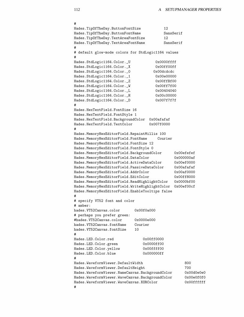
112 A SETUPMANAGER PROPERTIES
#Hades.TipOfTheDay.ButtonFontSize 12Hades.TipOfTheDay.ButtonFontName SansSerifHades.TipOfTheDay.TextAreaFontSize 12Hades.TipOfTheDay.TextAreaFontName SansSerif## default glow-mode colors for StdLogic1164 values#Hades.StdLogic1164.Color._U 0x0000ffffHades.StdLogic1164.Color._X 0x00ff00ffHades.StdLogic1164.Color._0 0x00dcdcdcHades.StdLogic1164.Color._1 0x00e00000Hades.StdLogic1164.Color._Z 0x00ffBf00Hades.StdLogic1164.Color._W 0x00ff7f00Hades.StdLogic1164.Color._L 0x00404040Hades.StdLogic1164.Color._H 0x00c00000Hades.StdLogic1164.Color._D 0x007f7f7f#Hades.HexTextField.FontSize 16Hades.HexTextField.FontStyle 1Hades.HexTextField.BackgroundColor 0x00afafafHades.HexTextField.TextColor 0x007f0000#Hades.MemoryHexEditorField.RepaintMillis 100Hades.MemoryHexEditorField.FontName CourierHades.MemoryHexEditorField.FontSize 12Hades.MemoryHexEditorField.FontStyle 0Hades.MemoryHexEditorField.BackgroundColor 0x00efefefHades.MemoryHexEditorField.DataColor 0x000000afHades.MemoryHexEditorField.ActiveDataColor 0x00ef0000Hades.MemoryHexEditorField.PassiveDataColor 0x00afafafHades.MemoryHexEditorField.AddrColor 0x00af0000Hades.MemoryHexEditorField.EditColor 0x00ff8000Hades.MemoryHexEditorField.ReadHighlightColor 0x0000bf00Hades.MemoryHexEditorField.WriteHighlightColor 0x00ef00cfHades.MemoryHexEditorField.EnableTooltips false## specify VT52 font and color# amber:hades.VT52Canvas.color 0x00f0a000# perhaps you prefer green:#hades.VT52Canvas.color 0x0000e000hades.VT52Canvas.fontName Courierhades.VT52Canvas.fontSize 10#Hades.LED.Color.red 0x00ff0000Hades.LED.Color.green 0x0000ff00Hades.LED.Color.yellow 0x00ffff00Hades.LED.Color.blue 0x000000ff#Hades.WaveformViewer.DefaultWidth 800Hades.WaveformViewer.DefaultHeight 700Hades.WaveformViewer.NameCanvas.BackgroundColor 0x00d0e0e0Hades.WaveformViewer.WaveCanvas.BackgroundColor 0x00e0f0f0Hades.WaveformViewer.WaveCanvas.XORColor 0x00ffffff#
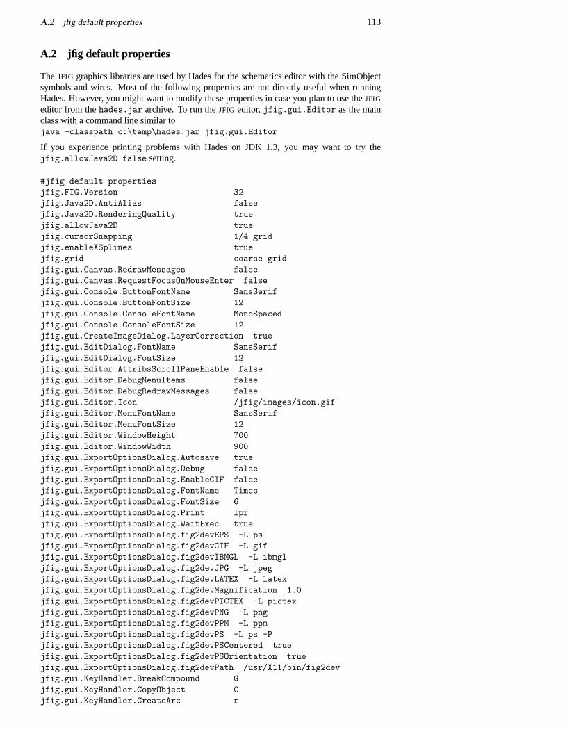
A.2 jfig default properties 113
A.2 jfig default properties
The JFIG graphics libraries are used by Hades for the schematics editor with the SimObjectsymbols and wires. Most of the following properties are not directly useful when runningHades. However, you might want to modify these properties in case you plan to use theJFIG
editor from thehades.jar archive. To run theJFIG editor,jfig.gui.Editor as the mainclass with a command line similar tojava -classpath c:\temp\hades.jar jfig.gui.Editor
If you experience printing problems with Hades on JDK 1.3, you may want to try thejfig.allowJava2D false setting.
#jfig default propertiesjfig.FIG.Version 32jfig.Java2D.AntiAlias falsejfig.Java2D.RenderingQuality truejfig.allowJava2D truejfig.cursorSnapping 1/4 gridjfig.enableXSplines truejfig.grid coarse gridjfig.gui.Canvas.RedrawMessages falsejfig.gui.Canvas.RequestFocusOnMouseEnter falsejfig.gui.Console.ButtonFontName SansSerifjfig.gui.Console.ButtonFontSize 12jfig.gui.Console.ConsoleFontName MonoSpacedjfig.gui.Console.ConsoleFontSize 12jfig.gui.CreateImageDialog.LayerCorrection truejfig.gui.EditDialog.FontName SansSerifjfig.gui.EditDialog.FontSize 12jfig.gui.Editor.AttribsScrollPaneEnable falsejfig.gui.Editor.DebugMenuItems falsejfig.gui.Editor.DebugRedrawMessages falsejfig.gui.Editor.Icon /jfig/images/icon.gifjfig.gui.Editor.MenuFontName SansSerifjfig.gui.Editor.MenuFontSize 12jfig.gui.Editor.WindowHeight 700jfig.gui.Editor.WindowWidth 900jfig.gui.ExportOptionsDialog.Autosave truejfig.gui.ExportOptionsDialog.Debug falsejfig.gui.ExportOptionsDialog.EnableGIF falsejfig.gui.ExportOptionsDialog.FontName Timesjfig.gui.ExportOptionsDialog.FontSize 6jfig.gui.ExportOptionsDialog.Print lprjfig.gui.ExportOptionsDialog.WaitExec truejfig.gui.ExportOptionsDialog.fig2devEPS -L psjfig.gui.ExportOptionsDialog.fig2devGIF -L gifjfig.gui.ExportOptionsDialog.fig2devIBMGL -L ibmgljfig.gui.ExportOptionsDialog.fig2devJPG -L jpegjfig.gui.ExportOptionsDialog.fig2devLATEX -L latexjfig.gui.ExportOptionsDialog.fig2devMagnification 1.0jfig.gui.ExportOptionsDialog.fig2devPICTEX -L pictexjfig.gui.ExportOptionsDialog.fig2devPNG -L pngjfig.gui.ExportOptionsDialog.fig2devPPM -L ppmjfig.gui.ExportOptionsDialog.fig2devPS -L ps -Pjfig.gui.ExportOptionsDialog.fig2devPSCentered truejfig.gui.ExportOptionsDialog.fig2devPSOrientation truejfig.gui.ExportOptionsDialog.fig2devPath /usr/X11/bin/fig2devjfig.gui.KeyHandler.BreakCompound Gjfig.gui.KeyHandler.CopyObject Cjfig.gui.KeyHandler.CreateArc r
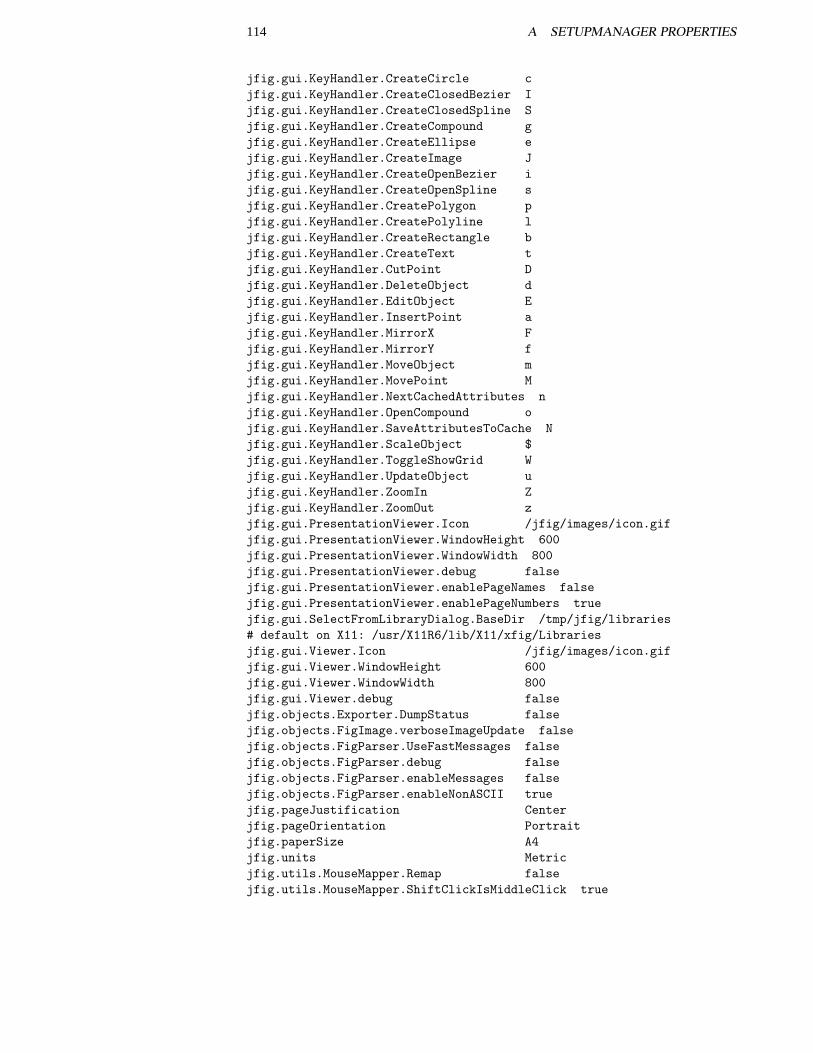
114 A SETUPMANAGER PROPERTIES
jfig.gui.KeyHandler.CreateCircle cjfig.gui.KeyHandler.CreateClosedBezier Ijfig.gui.KeyHandler.CreateClosedSpline Sjfig.gui.KeyHandler.CreateCompound gjfig.gui.KeyHandler.CreateEllipse ejfig.gui.KeyHandler.CreateImage Jjfig.gui.KeyHandler.CreateOpenBezier ijfig.gui.KeyHandler.CreateOpenSpline sjfig.gui.KeyHandler.CreatePolygon pjfig.gui.KeyHandler.CreatePolyline ljfig.gui.KeyHandler.CreateRectangle bjfig.gui.KeyHandler.CreateText tjfig.gui.KeyHandler.CutPoint Djfig.gui.KeyHandler.DeleteObject djfig.gui.KeyHandler.EditObject Ejfig.gui.KeyHandler.InsertPoint ajfig.gui.KeyHandler.MirrorX Fjfig.gui.KeyHandler.MirrorY fjfig.gui.KeyHandler.MoveObject mjfig.gui.KeyHandler.MovePoint Mjfig.gui.KeyHandler.NextCachedAttributes njfig.gui.KeyHandler.OpenCompound ojfig.gui.KeyHandler.SaveAttributesToCache Njfig.gui.KeyHandler.ScaleObject $jfig.gui.KeyHandler.ToggleShowGrid Wjfig.gui.KeyHandler.UpdateObject ujfig.gui.KeyHandler.ZoomIn Zjfig.gui.KeyHandler.ZoomOut zjfig.gui.PresentationViewer.Icon /jfig/images/icon.gifjfig.gui.PresentationViewer.WindowHeight 600jfig.gui.PresentationViewer.WindowWidth 800jfig.gui.PresentationViewer.debug falsejfig.gui.PresentationViewer.enablePageNames falsejfig.gui.PresentationViewer.enablePageNumbers truejfig.gui.SelectFromLibraryDialog.BaseDir /tmp/jfig/libraries# default on X11: /usr/X11R6/lib/X11/xfig/Librariesjfig.gui.Viewer.Icon /jfig/images/icon.gifjfig.gui.Viewer.WindowHeight 600jfig.gui.Viewer.WindowWidth 800jfig.gui.Viewer.debug falsejfig.objects.Exporter.DumpStatus falsejfig.objects.FigImage.verboseImageUpdate falsejfig.objects.FigParser.UseFastMessages falsejfig.objects.FigParser.debug falsejfig.objects.FigParser.enableMessages falsejfig.objects.FigParser.enableNonASCII truejfig.pageJustification Centerjfig.pageOrientation Portraitjfig.paperSize A4jfig.units Metricjfig.utils.MouseMapper.Remap falsejfig.utils.MouseMapper.ShiftClickIsMiddleClick true
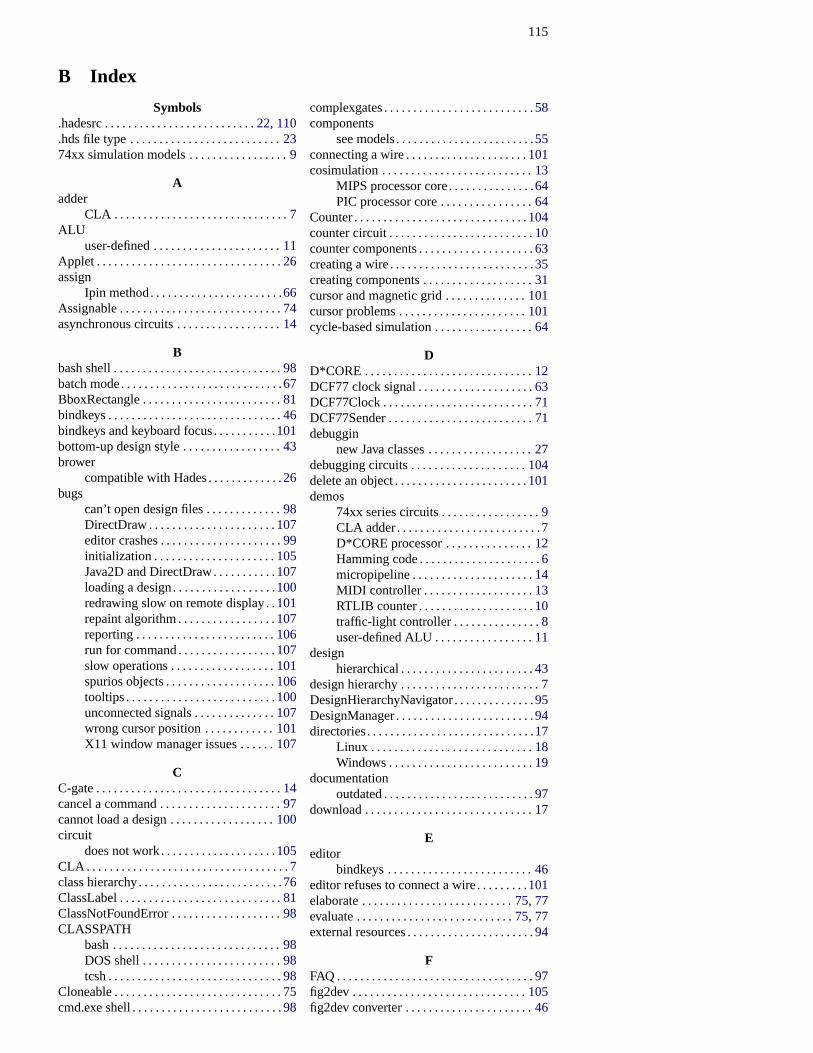
115
B Index
Symbols.hadesrc . . . . . . . . . . . . . . . . . . . . . . . . . .22, 110.hds file type . . . . . . . . . . . . . . . . . . . . . . . . . .2374xx simulation models . . . . . . . . . . . . . . . . .9
Aadder
CLA . . . . . . . . . . . . . . . . . . . . . . . . . . . . . .7ALU
user-defined . . . . . . . . . . . . . . . . . . . . . .11Applet . . . . . . . . . . . . . . . . . . . . . . . . . . . . . . . .26assign
Ipin method. . . . . . . . . . . . . . . . . . . . . . .66Assignable . . . . . . . . . . . . . . . . . . . . . . . . . . . .74asynchronous circuits . . . . . . . . . . . . . . . . . .14
Bbash shell . . . . . . . . . . . . . . . . . . . . . . . . . . . . .98batch mode. . . . . . . . . . . . . . . . . . . . . . . . . . . .67BboxRectangle . . . . . . . . . . . . . . . . . . . . . . . .81bindkeys . . . . . . . . . . . . . . . . . . . . . . . . . . . . . .46bindkeys and keyboard focus. . . . . . . . . . .101bottom-up design style . . . . . . . . . . . . . . . . .43brower
compatible with Hades. . . . . . . . . . . . .26bugs
can’t open design files . . . . . . . . . . . . .98DirectDraw . . . . . . . . . . . . . . . . . . . . . .107editor crashes . . . . . . . . . . . . . . . . . . . . .99initialization . . . . . . . . . . . . . . . . . . . . .105Java2D and DirectDraw. . . . . . . . . . .107loading a design. . . . . . . . . . . . . . . . . .100redrawing slow on remote display . .101repaint algorithm . . . . . . . . . . . . . . . . .107reporting . . . . . . . . . . . . . . . . . . . . . . . .106run for command . . . . . . . . . . . . . . . . .107slow operations . . . . . . . . . . . . . . . . . .101spurios objects . . . . . . . . . . . . . . . . . . .106tooltips . . . . . . . . . . . . . . . . . . . . . . . . . .100unconnected signals . . . . . . . . . . . . . .107wrong cursor position . . . . . . . . . . . .101X11 window manager issues . . . . . .107
CC-gate . . . . . . . . . . . . . . . . . . . . . . . . . . . . . . . .14cancel a command . . . . . . . . . . . . . . . . . . . . .97cannot load a design . . . . . . . . . . . . . . . . . .100circuit
does not work . . . . . . . . . . . . . . . . . . . .105CLA . . . . . . . . . . . . . . . . . . . . . . . . . . . . . . . . . . .7class hierarchy. . . . . . . . . . . . . . . . . . . . . . . . .76ClassLabel . . . . . . . . . . . . . . . . . . . . . . . . . . . .81ClassNotFoundError . . . . . . . . . . . . . . . . . . .98CLASSPATH
bash . . . . . . . . . . . . . . . . . . . . . . . . . . . . .98DOS shell . . . . . . . . . . . . . . . . . . . . . . . .98tcsh . . . . . . . . . . . . . . . . . . . . . . . . . . . . . .98
Cloneable . . . . . . . . . . . . . . . . . . . . . . . . . . . . .75cmd.exe shell . . . . . . . . . . . . . . . . . . . . . . . . . .98
complexgates . . . . . . . . . . . . . . . . . . . . . . . . . .58components
see models. . . . . . . . . . . . . . . . . . . . . . . .55connecting a wire . . . . . . . . . . . . . . . . . . . . .101cosimulation . . . . . . . . . . . . . . . . . . . . . . . . . .13
MIPS processor core. . . . . . . . . . . . . . .64PIC processor core . . . . . . . . . . . . . . . .64
Counter . . . . . . . . . . . . . . . . . . . . . . . . . . . . . .104counter circuit . . . . . . . . . . . . . . . . . . . . . . . . .10counter components . . . . . . . . . . . . . . . . . . . .63creating a wire . . . . . . . . . . . . . . . . . . . . . . . . .35creating components . . . . . . . . . . . . . . . . . . .31cursor and magnetic grid . . . . . . . . . . . . . .101cursor problems . . . . . . . . . . . . . . . . . . . . . .101cycle-based simulation . . . . . . . . . . . . . . . . .64
DD*CORE . . . . . . . . . . . . . . . . . . . . . . . . . . . . .12DCF77 clock signal . . . . . . . . . . . . . . . . . . . .63DCF77Clock . . . . . . . . . . . . . . . . . . . . . . . . . .71DCF77Sender . . . . . . . . . . . . . . . . . . . . . . . . .71debuggin
new Java classes . . . . . . . . . . . . . . . . . .27debugging circuits . . . . . . . . . . . . . . . . . . . .104delete an object . . . . . . . . . . . . . . . . . . . . . . .101demos
74xx series circuits . . . . . . . . . . . . . . . . .9CLA adder. . . . . . . . . . . . . . . . . . . . . . . . .7D*CORE processor . . . . . . . . . . . . . . .12Hamming code . . . . . . . . . . . . . . . . . . . . .6micropipeline . . . . . . . . . . . . . . . . . . . . .14MIDI controller . . . . . . . . . . . . . . . . . . .13RTLIB counter . . . . . . . . . . . . . . . . . . . .10traffic-light controller . . . . . . . . . . . . . . .8user-defined ALU . . . . . . . . . . . . . . . . .11
designhierarchical . . . . . . . . . . . . . . . . . . . . . . .43
design hierarchy . . . . . . . . . . . . . . . . . . . . . . . .7DesignHierarchyNavigator . . . . . . . . . . . . . .95DesignManager . . . . . . . . . . . . . . . . . . . . . . . .94directories. . . . . . . . . . . . . . . . . . . . . . . . . . . . .17
Linux . . . . . . . . . . . . . . . . . . . . . . . . . . . .18Windows . . . . . . . . . . . . . . . . . . . . . . . . .19
documentationoutdated . . . . . . . . . . . . . . . . . . . . . . . . . .97
download . . . . . . . . . . . . . . . . . . . . . . . . . . . . .17
Eeditor
bindkeys . . . . . . . . . . . . . . . . . . . . . . . . .46editor refuses to connect a wire. . . . . . . . .101elaborate . . . . . . . . . . . . . . . . . . . . . . . . . .75, 77evaluate . . . . . . . . . . . . . . . . . . . . . . . . . . .75, 77external resources . . . . . . . . . . . . . . . . . . . . . .94
FFAQ . . . . . . . . . . . . . . . . . . . . . . . . . . . . . . . . . .97fig2dev . . . . . . . . . . . . . . . . . . . . . . . . . . . . . .105fig2dev converter . . . . . . . . . . . . . . . . . . . . . .46
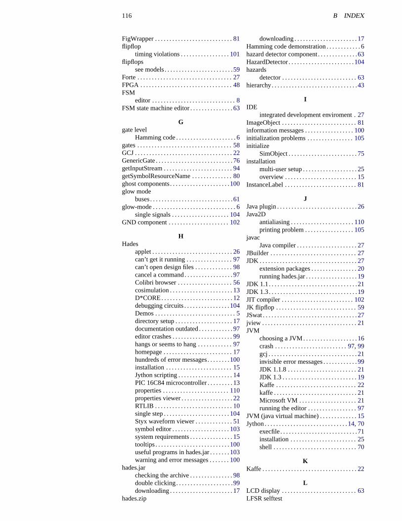
116 B INDEX
FigWrapper . . . . . . . . . . . . . . . . . . . . . . . . . . .81flipflop
timing violations . . . . . . . . . . . . . . . . .101flipflops
see models. . . . . . . . . . . . . . . . . . . . . . . .59Forte . . . . . . . . . . . . . . . . . . . . . . . . . . . . . . . . .27FPGA . . . . . . . . . . . . . . . . . . . . . . . . . . . . . . . .48FSM
editor . . . . . . . . . . . . . . . . . . . . . . . . . . . . .8FSM state machine editor . . . . . . . . . . . . . . .63
Ggate level
Hamming code . . . . . . . . . . . . . . . . . . . . .6gates . . . . . . . . . . . . . . . . . . . . . . . . . . . . . . . . .58GCJ . . . . . . . . . . . . . . . . . . . . . . . . . . . . . . . . . .22GenericGate . . . . . . . . . . . . . . . . . . . . . . . . . . .76getInputStream . . . . . . . . . . . . . . . . . . . . . . . .94getSymbolResourceName . . . . . . . . . . . . . .80ghost components. . . . . . . . . . . . . . . . . . . . .100glow mode
buses. . . . . . . . . . . . . . . . . . . . . . . . . . . . .61glow-mode . . . . . . . . . . . . . . . . . . . . . . . . . . . . .6
single signals . . . . . . . . . . . . . . . . . . . .104GND component . . . . . . . . . . . . . . . . . . . . .102
HHades
applet . . . . . . . . . . . . . . . . . . . . . . . . . . . .26can’t get it running . . . . . . . . . . . . . . . .97can’t open design files . . . . . . . . . . . . .98cancel a command . . . . . . . . . . . . . . . . .97Colibri browser . . . . . . . . . . . . . . . . . . .56cosimulation . . . . . . . . . . . . . . . . . . . . . .13D*CORE . . . . . . . . . . . . . . . . . . . . . . . . .12debugging circuits . . . . . . . . . . . . . . . .104Demos . . . . . . . . . . . . . . . . . . . . . . . . . . . .5directory setup . . . . . . . . . . . . . . . . . . . .17documentation outdated . . . . . . . . . . . .97editor crashes . . . . . . . . . . . . . . . . . . . . .99hangs or seems to hang . . . . . . . . . . . .97homepage . . . . . . . . . . . . . . . . . . . . . . . .17hundreds of error messages. . . . . . . .100installation . . . . . . . . . . . . . . . . . . . . . . .15Jython scripting . . . . . . . . . . . . . . . . . . .14PIC 16C84 microcontroller . . . . . . . . .13properties . . . . . . . . . . . . . . . . . . . . . . .110properties viewer . . . . . . . . . . . . . . . . . .22RTLIB . . . . . . . . . . . . . . . . . . . . . . . . . . .10single step . . . . . . . . . . . . . . . . . . . . . . .104Styx waveform viewer . . . . . . . . . . . . .51symbol editor . . . . . . . . . . . . . . . . . . . .103system requirements . . . . . . . . . . . . . . .15tooltips . . . . . . . . . . . . . . . . . . . . . . . . . .100useful programs in hades.jar . . . . . . .103warning and error messages . . . . . . .100
hades.jarchecking the archive . . . . . . . . . . . . . . .98double clicking. . . . . . . . . . . . . . . . . . . .99downloading . . . . . . . . . . . . . . . . . . . . . .17
hades.zip
downloading . . . . . . . . . . . . . . . . . . . . . .17Hamming code demonstration . . . . . . . . . . . .6hazard detector component. . . . . . . . . . . . . .63HazardDetector . . . . . . . . . . . . . . . . . . . . . . .104hazards
detector . . . . . . . . . . . . . . . . . . . . . . . . . .63hierarchy. . . . . . . . . . . . . . . . . . . . . . . . . . . . . .43
IIDE
integrated development enviroment .27ImageObject . . . . . . . . . . . . . . . . . . . . . . . . . .81information messages . . . . . . . . . . . . . . . . .100initialization problems . . . . . . . . . . . . . . . .105initialize
SimObject . . . . . . . . . . . . . . . . . . . . . . . .75installation
multi-user setup . . . . . . . . . . . . . . . . . . .25overview . . . . . . . . . . . . . . . . . . . . . . . . .15
InstanceLabel . . . . . . . . . . . . . . . . . . . . . . . . .81
JJava plugin . . . . . . . . . . . . . . . . . . . . . . . . . . . .26Java2D
antialiasing . . . . . . . . . . . . . . . . . . . . . .110printing problem . . . . . . . . . . . . . . . . .105
javacJava compiler . . . . . . . . . . . . . . . . . . . . .27
JBuilder . . . . . . . . . . . . . . . . . . . . . . . . . . . . . .27JDK . . . . . . . . . . . . . . . . . . . . . . . . . . . . . . . . . .27
extension packages . . . . . . . . . . . . . . . .20running hades.jar . . . . . . . . . . . . . . . . . .19
JDK 1.1. . . . . . . . . . . . . . . . . . . . . . . . . . . . . . .21JDK 1.3. . . . . . . . . . . . . . . . . . . . . . . . . . . . . . .19JIT compiler . . . . . . . . . . . . . . . . . . . . . . . . .102JK flipflop . . . . . . . . . . . . . . . . . . . . . . . . . . . .59JSwat . . . . . . . . . . . . . . . . . . . . . . . . . . . . . . . . .27jview . . . . . . . . . . . . . . . . . . . . . . . . . . . . . . . . .21JVM
choosing a JVM. . . . . . . . . . . . . . . . . . .16crash . . . . . . . . . . . . . . . . . . . . . . . . .97, 99gcj . . . . . . . . . . . . . . . . . . . . . . . . . . . . . . .21invisible error messages . . . . . . . . . . . .99JDK 1.1.8 . . . . . . . . . . . . . . . . . . . . . . . .21JDK 1.3 . . . . . . . . . . . . . . . . . . . . . . . . . .19Kaffe . . . . . . . . . . . . . . . . . . . . . . . . . . . .22kaffe . . . . . . . . . . . . . . . . . . . . . . . . . . . . .21Microsoft VM . . . . . . . . . . . . . . . . . . . .21running the editor . . . . . . . . . . . . . . . . .97
JVM (java virtual machine) . . . . . . . . . . . . .15Jython . . . . . . . . . . . . . . . . . . . . . . . . . . . . .14, 70
execfile . . . . . . . . . . . . . . . . . . . . . . . . . . .71installation . . . . . . . . . . . . . . . . . . . . . . .25shell . . . . . . . . . . . . . . . . . . . . . . . . . . . . .70
KKaffe . . . . . . . . . . . . . . . . . . . . . . . . . . . . . . . . .22
LLCD display . . . . . . . . . . . . . . . . . . . . . . . . . .63LFSR selftest
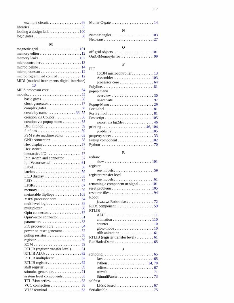
117
example circuit . . . . . . . . . . . . . . . . . . . .68libraries . . . . . . . . . . . . . . . . . . . . . . . . . . . . . . .55loading a design fails . . . . . . . . . . . . . . . . . .100logic gates . . . . . . . . . . . . . . . . . . . . . . . . . . . .58
Mmagnetic grid . . . . . . . . . . . . . . . . . . . . . . . .101memory editor . . . . . . . . . . . . . . . . . . . . . . . . .12memory leaks . . . . . . . . . . . . . . . . . . . . . . . .102microcontroller . . . . . . . . . . . . . . . . . . . . . . . .13micropipeline . . . . . . . . . . . . . . . . . . . . . . . . .14microprocessor . . . . . . . . . . . . . . . . . . . . . . . .12microprogrammed control . . . . . . . . . . . . . .12MIDI (musical instruments digital interface)
13MIPS processor core . . . . . . . . . . . . . . . . . . .64models. . . . . . . . . . . . . . . . . . . . . . . . . . . . . . . .55
basic gates . . . . . . . . . . . . . . . . . . . . . . . .58clock generator. . . . . . . . . . . . . . . . . . . .57complex gates. . . . . . . . . . . . . . . . . . . . .58create by name . . . . . . . . . . . . . . . .33, 55creation via Colibri . . . . . . . . . . . . . . . .56creation via popup menu . . . . . . . . . . .55DFF flipflop . . . . . . . . . . . . . . . . . . . . . .59flipflops . . . . . . . . . . . . . . . . . . . . . . . . . .59FSM state machine editor . . . . . . . . . .63GND connection . . . . . . . . . . . . . . . . . .58Hex display . . . . . . . . . . . . . . . . . . . . . . .57Hex switch . . . . . . . . . . . . . . . . . . . . . . .57interactive I/O . . . . . . . . . . . . . . . . . . . .57Ipin switch and connector . . . . . . . . . .57IpinVector switch . . . . . . . . . . . . . . . . .61Label . . . . . . . . . . . . . . . . . . . . . . . . . . . .56latches . . . . . . . . . . . . . . . . . . . . . . . . . . .59LCD display . . . . . . . . . . . . . . . . . . . . . .63LED . . . . . . . . . . . . . . . . . . . . . . . . . . . . .57LFSRs . . . . . . . . . . . . . . . . . . . . . . . . . . .67memory . . . . . . . . . . . . . . . . . . . . . . . . . .59metastable flipflops . . . . . . . . . . . . . . .105MIPS processor core. . . . . . . . . . . . . . .64multilevel logic . . . . . . . . . . . . . . . . . . .38multiplexer . . . . . . . . . . . . . . . . . . . . . . .58Opin connector. . . . . . . . . . . . . . . . . . . .57OpinVector connector . . . . . . . . . . . . . .61parameters . . . . . . . . . . . . . . . . . . . . . . . .33PIC processor core . . . . . . . . . . . . . . . .64power on reset generator . . . . . . . . . . .57pullup resistor. . . . . . . . . . . . . . . . . . . . .58register . . . . . . . . . . . . . . . . . . . . . . . . . . .59ROM . . . . . . . . . . . . . . . . . . . . . . . . . . . .59RTLIB (register transfer level) . . . . . .61RTLIB ALUs . . . . . . . . . . . . . . . . . . . . .62RTLIB multiplexer . . . . . . . . . . . . . . . .62RTLIB register . . . . . . . . . . . . . . . . . . . .62shift register . . . . . . . . . . . . . . . . . . . . . .59stimulus generator . . . . . . . . . . . . . . . . .71system level components . . . . . . . . . . .63TTL 74xx series. . . . . . . . . . . . . . . . . . .63VCC connection . . . . . . . . . . . . . . . . . .58VT52 terminal . . . . . . . . . . . . . . . . . . . .63
Muller C-gate . . . . . . . . . . . . . . . . . . . . . . . . .14
NNameMangler . . . . . . . . . . . . . . . . . . . . . . . .103Netbeans . . . . . . . . . . . . . . . . . . . . . . . . . . . . . .27
Ooff-grid objects . . . . . . . . . . . . . . . . . . . . . . .101OutOfMemoryError . . . . . . . . . . . . . . . . . . . .99
PPIC
16C84 microcontroller . . . . . . . . . . . . .13Assembler . . . . . . . . . . . . . . . . . . . . . . .103processor core . . . . . . . . . . . . . . . . . . . .64
Polyline. . . . . . . . . . . . . . . . . . . . . . . . . . . . . . .81popup menu
overview . . . . . . . . . . . . . . . . . . . . . . . . .30re-activate . . . . . . . . . . . . . . . . . . . . . . . .97
Popup-Menu . . . . . . . . . . . . . . . . . . . . . . . . . .29PortLabel . . . . . . . . . . . . . . . . . . . . . . . . . . . . .81PortSymbol . . . . . . . . . . . . . . . . . . . . . . . . . . .81Postscript . . . . . . . . . . . . . . . . . . . . . . . . . . . .105
export via fig2dev . . . . . . . . . . . . . . . . .46printing . . . . . . . . . . . . . . . . . . . . . . . . . .46, 104
problems . . . . . . . . . . . . . . . . . . . . . . . .105property sheet . . . . . . . . . . . . . . . . . . . . . . . . .33Pullup component . . . . . . . . . . . . . . . . . . . .102Python . . . . . . . . . . . . . . . . . . . . . . . . . . . . . . . .70
Rredraw
slow . . . . . . . . . . . . . . . . . . . . . . . . . . . .101register
see models. . . . . . . . . . . . . . . . . . . . . . . .59register transfer level
see models. . . . . . . . . . . . . . . . . . . . . . . .61renaming a component or signal . . . . . . . .101reset problems . . . . . . . . . . . . . . . . . . . . . . . .105resource files . . . . . . . . . . . . . . . . . . . . . . . . . .94Robot
java.awt.Robot class . . . . . . . . . . . . . . .72ROM component . . . . . . . . . . . . . . . . . . . . . .59RTLIB
ALU . . . . . . . . . . . . . . . . . . . . . . . . . . . . .11animation . . . . . . . . . . . . . . . . . . . . . . .110counter . . . . . . . . . . . . . . . . . . . . . . . . . . .10glow-mode . . . . . . . . . . . . . . . . . . . . . . .10rtlib animation . . . . . . . . . . . . . . . . . . . .61
RTLIB (register transfer level) . . . . . . . . . .61RunHadesDemo . . . . . . . . . . . . . . . . . . . . . . .65
Sscripting . . . . . . . . . . . . . . . . . . . . . . . . . . . . . .65
Java . . . . . . . . . . . . . . . . . . . . . . . . . . . . . .65Jython . . . . . . . . . . . . . . . . . . . . . . . .14, 70selftest . . . . . . . . . . . . . . . . . . . . . . . . . . .67stimuli . . . . . . . . . . . . . . . . . . . . . . . . . . .71StimuliParser . . . . . . . . . . . . . . . . . . . . .73
selftestLFSR based . . . . . . . . . . . . . . . . . . . . . .67
Serializable . . . . . . . . . . . . . . . . . . . . . . . . . . .75
118 B INDEX
SetupManager . . . . . . . . . . . . . . . . . . . .65, 110signals
adding wire segments . . . . . . . . . . . . . .35cannot create. . . . . . . . . . . . . . . . . . . . . .35connecting wires . . . . . . . . . . . . . . . . . .36creating wires . . . . . . . . . . . . . . . . . . . . .35disable create signals . . . . . . . . . . . . . .35move wire points . . . . . . . . . . . . . . . . . .36
SimObjectclass hierarchy . . . . . . . . . . . . . . . . . . . .76constructor . . . . . . . . . . . . . . . . . . . . . . .83elaborate . . . . . . . . . . . . . . . . . . . . . . . . .77evaluate . . . . . . . . . . . . . . . . . . . . . . . . . .77external resources . . . . . . . . . . . . . . . . .94methods . . . . . . . . . . . . . . . . . . . . . . . . . .75overview . . . . . . . . . . . . . . . . . . . . . . . . .75symbol . . . . . . . . . . . . . . . . . . . . . . . . . . .80
SimObjectNotFoundException . . . . . . . . .100Simulatable . . . . . . . . . . . . . . . . . . . . . . . .75, 76simulation
batch-mode . . . . . . . . . . . . . . . . . . . . . . .67in-deterministic . . . . . . . . . . . . . . . . . .105slow . . . . . . . . . . . . . . . . . . . . . . . . . . . .102vs. real circuits . . . . . . . . . . . . . . . . . .105
simulation modelssee models. . . . . . . . . . . . . . . . . . . . . . . .55
simulatoralgorithms . . . . . . . . . . . . . . . . . . . . . . . .29autostart property . . . . . . . . . . . . . . . .110cycle-based . . . . . . . . . . . . . . . . . . . . . . .64event-driven . . . . . . . . . . . . . . . . . . . . . .64fast synchronization . . . . . . . . . . . . . . .64runForever . . . . . . . . . . . . . . . . . . . . . . . .66VHDL . . . . . . . . . . . . . . . . . . . . . . . . . . .29
slow operations . . . . . . . . . . . . . . . . . . . . . . .101state machine editor . . . . . . . . . . . . . . . . . . . . .8std logic . . . . . . . . . . . . . . . . . . . . . . . . . . .38, 58std logic vector . . . . . . . . . . . . . . . . . . . . . . . .61StimuliGenerator . . . . . . . . . . . . . . . . . . . . . .73StimuliParser . . . . . . . . . . . . . . . . . . . . . . . . . .73Stimulus . . . . . . . . . . . . . . . . . . . . . . . . . . . . . .71STL
stimuli language . . . . . . . . . . . . . . . . . .72Symbol
SimObject graphical representation .80symbol file . . . . . . . . . . . . . . . . . . . . . . . . . . . .80Synopsys VSS. . . . . . . . . . . . . . . . . . . . . . . .106system requirements . . . . . . . . . . . . . . . . . . .15
Ttcsh shell . . . . . . . . . . . . . . . . . . . . . . . . . . . . . .98TGX (slow graphics) . . . . . . . . . . . . . . . . . . .21Thread
synchronisation . . . . . . . . . . . . . . . . . . .67timing violations
unexpected . . . . . . . . . . . . . . . . . . . . . . .41Tips . . . . . . . . . . . . . . . . . . . . . . . . . . . . . . . . . .97
tooltipsdisable . . . . . . . . . . . . . . . . . . . . . . . . . .100
top-down design style . . . . . . . . . . . . . . . . . .43traffic-light example . . . . . . . . . . . . . . . . . . . . .8Tricks . . . . . . . . . . . . . . . . . . . . . . . . . . . . . . . .97TTL circuits . . . . . . . . . . . . . . . . . . . . . . . . . . .63TTL series simulation models . . . . . . . . . . . .9two-phase clock . . . . . . . . . . . . . . . . . . . . . .104
Uundefined values . . . . . . . . . . . . . . . . . . . . . .102user preferences . . . . . . . . . . . . . . . . . . . . . . .22
VVCC component . . . . . . . . . . . . . . . . . . . . . .102VHDL
export . . . . . . . . . . . . . . . . . . . . . . .48, 106name mangling. . . . . . . . . . . . . . . . . . . .49std logic . . . . . . . . . . . . . . . . . . . .6, 38, 58std logic vector . . . . . . . . . . . . . . . . . . .61stimuli specification . . . . . . . . . . . . . . .73
VHDLExportable . . . . . . . . . . . . . . . . . . . . . .50VHDLModelFactory . . . . . . . . . . . . . . . . . . .49VHDLWriter. . . . . . . . . . . . . . . . . . . . . .48, 106VisualAge. . . . . . . . . . . . . . . . . . . . . . . . . . . . .27VT52 terminal
parallel interface . . . . . . . . . . . . . . . . . .63serial interface . . . . . . . . . . . . . . . . . . . .63
Wwaekup . . . . . . . . . . . . . . . . . . . . . . . . . . . . . . .75Wakeable . . . . . . . . . . . . . . . . . . . . . . . . . . . . .76wakeup . . . . . . . . . . . . . . . . . . . . . . . . . . . . . . .77warning messages . . . . . . . . . . . . . . . . . . . .100waveform viewer . . . . . . . . . . . . . . . . . . . . . .51
usage . . . . . . . . . . . . . . . . . . . . . . . . . . . .52waveforms
saving and loading . . . . . . . . . . . . . . . .53scripting . . . . . . . . . . . . . . . . . . . . . . . . . .54searching . . . . . . . . . . . . . . . . . . . . . . . . .53types . . . . . . . . . . . . . . . . . . . . . . . . . . . . .52
windowsize and position . . . . . . . . . . . . . . . . .110
Windows.hds file type . . . . . . . . . . . . . . . . . . . . . .23explorer troubles . . . . . . . . . . . . . . . . . .17
writeSimObject . . . . . . . . . . . . . . . . . . . . . . . .75
XX11
slow (remote display) . . . . . . . . . . . . .101window manager issues . . . . . . . . . . .107
Zzip: protocol . . . . . . . . . . . . . . . . . . . . . . . . . .95