Embed Size (px)
Citation preview
HabitOwner’s Manual Supplement
READ THIS SUPPLEMENT AND YOUR CANNONDALE BICYCLE OWNER’S MANUAL. Both contain important safety information. Keep both for future reference.
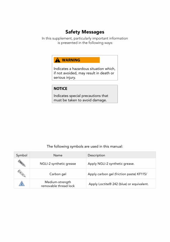
Safety MessagesIn this supplement, particularly important information
is presented in the following ways:
Indicates a hazardous situation which, if not avoided, may result in death or serious injury.
NOTICE
Indicates special precautions that must be taken to avoid damage.
The following symbols are used in this manual:
Symbol Name DescriptionNGLI-2 NGLI-2 synthetic grease Apply NGLI-2 synthetic grease.
CRB-GEL Carbon gel Apply carbon gel (friction paste) KF115/
2 Medium-strength removable thread lock Apply Loctite® 242 (blue) or equivalent.
1134938 Rev 1.
EnglishHabit - Owners Manual Supplement
CONTENTSSafety Information ............................2-6
Technical Information ......................7-27
Replacement Parts ........................28-29
Tightening Torques ............................ 30
Maintenance ....................................... 31
Notes .................................................. 32
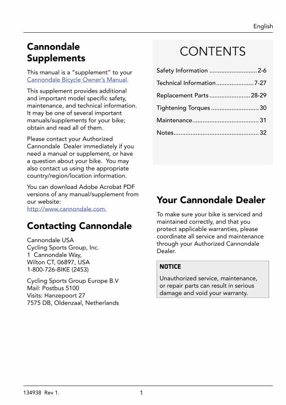
Cannondale Supplements This manual is a “supplement” to your Cannondale Bicycle Owner’s Manual.
This supplement provides additional and important model specific safety, maintenance, and technical information. It may be one of several important manuals/supplements for your bike; obtain and read all of them.
Please contact your Authorized Cannondale Dealer immediately if you need a manual or supplement, or have a question about your bike. You may also contact us using the appropriate country/region/location information.
You can download Adobe Acrobat PDF versions of any manual/supplement from our website: http://www.cannondale.com.
Contacting CannondaleCannondale USA Cycling Sports Group, Inc. 1 Cannondale Way, Wilton CT, 06897, USA 1-800-726-BIKE (2453)
Cycling Sports Group Europe B.V Mail: Postbus 5100 Visits: Hanzepoort 27 7575 DB, Oldenzaal, Netherlands
Your Cannondale DealerTo make sure your bike is serviced and maintained correctly, and that you protect applicable warranties, please coordinate all service and maintenance through your Authorized Cannondale Dealer.
NOTICE
Unauthorized service, maintenance, or repair parts can result in serious damage and void your warranty.
2134938 Rev 1.
EnglishHabit - Owners Manual Supplement
SAFETY INFORMATION
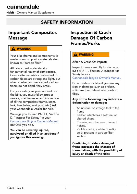
Important Composites Message
Your bike (frame and components) is made from composite materials also known as “carbon fiber.”
All riders must understand a fundamental reality of composites. Composite materials constructed of carbon fibers are strong and light, but when crashed or overloaded, carbon fibers do not bend, they break.
For your safety, as you own and use the bike, you must follow proper service, maintenance, and inspection of all the composites (frame, stem, fork, handlebar, seat post, etc.) Ask your Cannondale Dealer for help.
We urge you to read PART II, Section D. “Inspect For Safety” in your Cannondale Bicycle Owner’s Manual BEFORE you ride.
You can be severely injured, paralyzed or killed in an accident if you ignore this warning.
Inspection & Crash Damage Of Carbon Frames/Forks
After A Crash Or Impact:
Inspect frame carefully for damage (See PART II, Section D. Inspect For Safety in your Cannondale Bicycle Owner’s Manual.
Do not ride your bike if you see any sign of damage, such as broken, splintered, or delaminated carbon fiber.
Any of the following may indicate a delamination or damage:
· An unusual or strange feel to the frame
· Carbon which has a soft feel or altered shape
· Creaking or other unexplained noises,
· Visible cracks, a white or milky color present in carbon fiber section
Continuing to ride a damaged frame increases the chances of frame failure, with the possibility of injury or death of the rider.
3134938 Rev 1.
EnglishHabit - Owners Manual Supplement
Intended Use
The intended use of all models is ASTM CONDITION 4, All-Mountain.
Understand your bike and its intended use. Using your bike the wrong way is dangerous.
Please read your Cannondale Bicycle Owner’s Manual for more information about Intended Use and Conditions 1-5.
Servicing
This supplement may include procedures beyond the scope of general mechanical aptitude.
Special tools, skills, and knowledge may be required. Improper mechanical work increases the risk of an accident. Any bicycle accident has risk of serious injury, paralysis or death.
To minimize risk we strongly recommend that owners always have mechanical work done by an Authorized Cannondale Dealer.
4134938 Rev 1.
.
EnglishHabit - Owners Manual Supplement
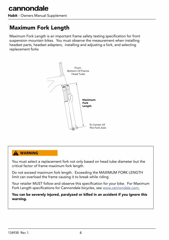
Maximum Fork LengthMaximum Fork Length is an important frame safety testing specification for front suspension mountain bikes. You must observe the measurement when installing headset parts, headset adapters, installing and adjusting a fork, and selecting replacement forks
You must select a replacement fork not only based on head tube diameter but the critical factor of frame maximum fork length.
Do not exceed maximum fork length. Exceeding the MAXIMUM FORK LENGTH limit can overload the frame causing it to break while riding.
Your retailer MUST follow and observe this specification for your bike. For Maximum Fork Length specifications for Cannondale bicycles, see www.cannondale.com.
You can be severely injured, paralyzed or killed in an accident if you ignore this warning.
To Center Of The Fork Axle
From Bottom Of Frame
Head Tube
MaximumForkLength
5134938 Rev 1.
EnglishHabit - Owners Manual Supplement
Tire Size x Maximum Width
Observe the Tire Size x Maximum Width for your bike found in the “Specifications” page of this manual.
Mounting the wrong size tires can result in the tires hitting the fork or frame when riding. If this happens, you can lose control of your bike and you can be thrown off, a moving tire can be stopped because it touches the fork or frame.
Do not mount oversized tires, ones that rub or hit the fork or frame, ones that result in too little clearance, or ones that can hit the fork or frame when the suspension is fully compressed or when riding.
Take care that the tires you select are compatible with your bike’s fork or frame design. Also, be sure to follow the manufacturer’s recommendations of your front fork and rear shocks.
When you are considering tires for your bike consider...
The actual measured size of a tire may be different than its sidewall marking. Each time you mount a new tire, take the time to inspect the actual clearance between the rotating tire and all parts of the frame. The U.S. Consumer Product Safety Commission (CPSC) requires at least 1/16” (1.6 mm) tire clearance from any part of the bike. Allowing for lateral rim flex and a wheel or rim that is out-of-true will likely mean choosing a rear tire that provides even more clearance than the CPSC recommends.
Ask your dealer for the right tires for your bike and its particular components!
You can be severely injured, paralyzed or killed in an accident if you ignore this warning.
6134938 Rev 1.
EnglishHabit - Owners Manual Supplement
Minimum Seat Post Insert
Make sure at least 100 mm of the seat post is inserted into the frame at all times.
Failure to insert the seat post at least 100 mm can place a very high stress on the seat tube top tube junction causing the frame to fail while riding.
Remove the seat post. Measure 100 mm from the bottom of the seat post. Use a permanent marker to mark the post at 100 mm.
When adjusting the seat post height in the seat tube, never adjust the seat post so that the line you mark is above the top edge of the seat tube.
You must also be aware that bicycle seat posts are permanently marked by the manufacturer with a “minimum insert” line on the seat post itself. You must not rely on this marking as an indication of the proper minimum seat post insertion depth.
You can be severely injured, paralyzed or killed in an accident if you ignore this warning.
Rear Shocks
Select only compatible shocks and forks for your bike. Do not modify your bike in any way to mount one.
Have your shock or fork installed by a professional bike mechanic
Riding with the wrong rear shock can damage the frame. You could have a serious accident. Make sure the total travel, eye-to-eye length, and stroke length of the rear shock you select meet the “Specifications” listed in this manual.
When selecting different shocks or forks for your bike, make sure that the shock or fork you select is compatible with your bike’s design and how you will use your bike.
You can be severely injured, paralyzed or killed in an accident if you ignore this warning.
7134938 Rev 1.
EnglishHabit - Owners Manual Supplement
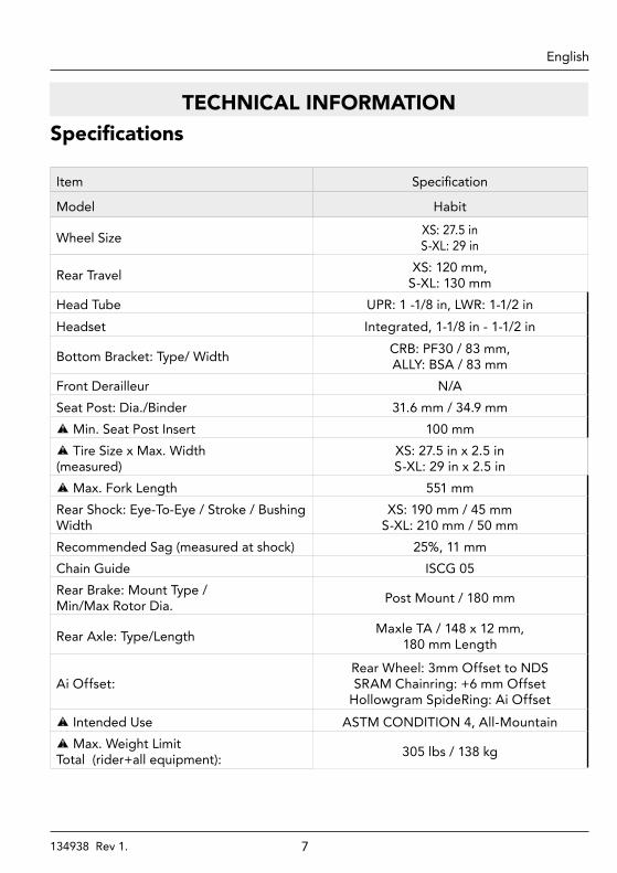
TECHNICAL INFORMATIONSpecifications
Item Specification
Model Habit
Wheel Size XS: 27.5 inS-XL: 29 in
Rear Travel XS: 120 mm, S-XL: 130 mm
Head Tube UPR: 1 -1/8 in, LWR: 1-1/2 inHeadset Integrated, 1-1/8 in - 1-1/2 in
Bottom Bracket: Type/ Width CRB: PF30 / 83 mm, ALLY: BSA / 83 mm
Front Derailleur N/ASeat Post: Dia./Binder 31.6 mm / 34.9 mm
Min. Seat Post Insert 100 mm Tire Size x Max. Width
(measured) XS: 27.5 in x 2.5 in S-XL: 29 in x 2.5 in
Max. Fork Length 551 mmRear Shock: Eye-To-Eye / Stroke / Bushing Width
XS: 190 mm / 45 mmS-XL: 210 mm / 50 mm
Recommended Sag (measured at shock) 25%, 11 mmChain Guide ISCG 05Rear Brake: Mount Type / Min/Max Rotor Dia. Post Mount / 180 mm
Rear Axle: Type/Length Maxle TA / 148 x 12 mm, 180 mm Length
Ai Offset:Rear Wheel: 3mm Offset to NDS SRAM Chainring: +6 mm Offset
Hollowgram SpideRing: Ai Offset Intended Use ASTM CONDITION 4, All-Mountain Max. Weight Limit
Total (rider+all equipment): 305 lbs / 138 kg
8134938 Rev 1.
EnglishHabit - Owners Manual Supplement
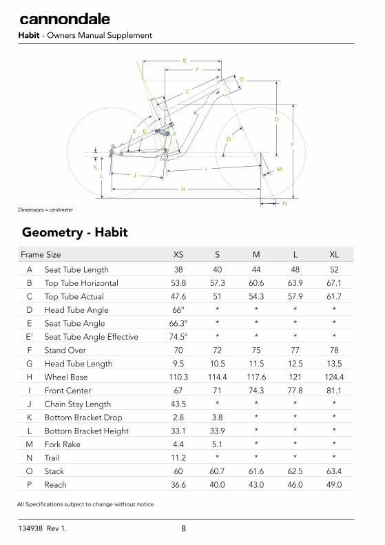
Frame Size XS S M L XL
A Seat Tube Length 38 40 44 48 52
B Top Tube Horizontal 53.8 57.3 60.6 63.9 67.1
C Top Tube Actual 47.6 51 54.3 57.9 61.7
D Head Tube Angle 66° * * * *
E Seat Tube Angle 66.3° * * * *
E1 Seat Tube Angle Effective 74.5° * * * *
F Stand Over 70 72 75 77 78
G Head Tube Length 9.5 10.5 11.5 12.5 13.5
H Wheel Base 110.3 114.4 117.6 121 124.4
I Front Center 67 71 74.3 77.8 81.1
J Chain Stay Length 43.5 * * * *
K Bottom Bracket Drop 2.8 3.8 * * *
L Bottom Bracket Height 33.1 33.9 * * *
M Fork Rake 4.4 5.1 * * *
N Trail 11.2 * * * *
O Stack 60 60.7 61.6 62.5 63.4
P Reach 36.6 40.0 43.0 46.0 49.0
Geometry - Habit
G
O
BP
DE
L J
H
I
A
K M
F
N
E’
C
All Specifications subject to change without notice.
Dimensions = centimeter
9134938 Rev 1.
EnglishHabit - Owners Manual Supplement
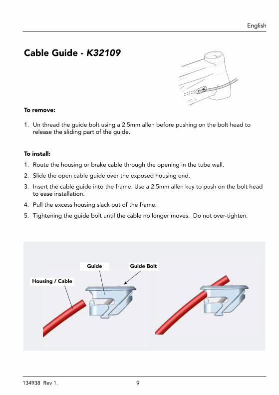
To remove:
1. Un thread the guide bolt using a 2.5mm allen before pushing on the bolt head to release the sliding part of the guide.
To install:
1. Route the housing or brake cable through the opening in the tube wall.
2. Slide the open cable guide over the exposed housing end.
3. Insert the cable guide into the frame. Use a 2.5mm allen key to push on the bolt head to ease installation.
4. Pull the excess housing slack out of the frame.
5. Tightening the guide bolt until the cable no longer moves. Do not over-tighten.
Cable Guide - K32109
Guide BoltGuide
Housing / Cable
10134938 Rev 1.
EnglishHabit - Owners Manual Supplement
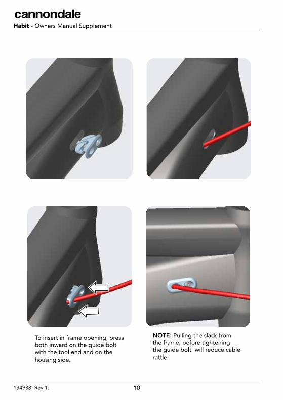
To insert in frame opening, press both inward on the guide bolt with the tool end and on the housing side.
NOTE: Pulling the slack from the frame, before tightening the guide bolt will reduce cable rattle.
11134938 Rev 1.
EnglishHabit - Owners Manual Supplement
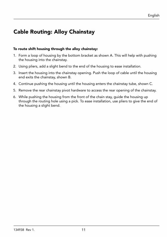
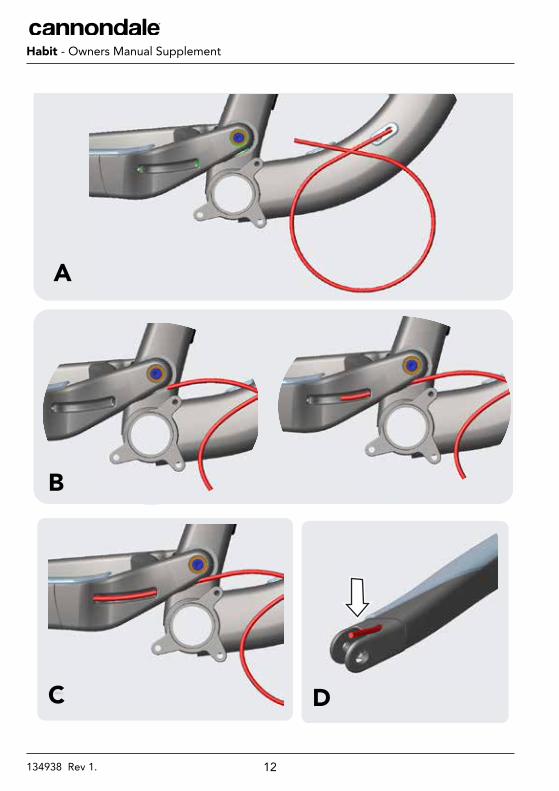
To route shift housing through the alloy chainstay:
1. Form a loop of housing by the bottom bracket as shown A. This will help with pushing the housing into the chainstay.
2. Using pliers, add a slight bend to the end of the housing to ease installation.
3. Insert the housing into the chainstay opening. Push the loop of cable until the housing end exits the chainstay, shown B.
4. Continue pushing the housing until the housing enters the chainstay tube, shown C.
5. Remove the rear chainstay pivot hardware to access the rear opening of the chainstay.
6. While pushing the housing from the front of the chain stay, guide the housing up through the routing hole using a pick. To ease installation, use pliers to give the end of the housing a slight bend.
Cable Routing: Alloy Chainstay
12134938 Rev 1.
EnglishHabit - Owners Manual Supplement
A
B
C D
13134938 Rev 1.
EnglishHabit - Owners Manual Supplement
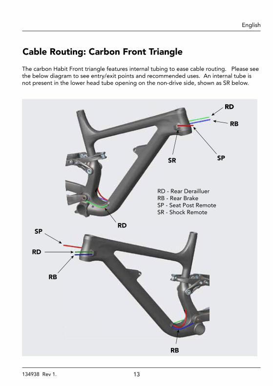
The carbon Habit Front triangle features internal tubing to ease cable routing. Please see the below diagram to see entry/exit points and recommended uses. An internal tube is not present in the lower head tube opening on the non-drive side, shown as SR below.
Cable Routing: Carbon Front Triangle
RDRD
RB
SPSR
RD
RD
RB
SP
RB
RD - Rear DerailluerRB - Rear BrakeSP - Seat Post RemoteSR - Shock Remote
14134938 Rev 1.
EnglishHabit - Owners Manual Supplement
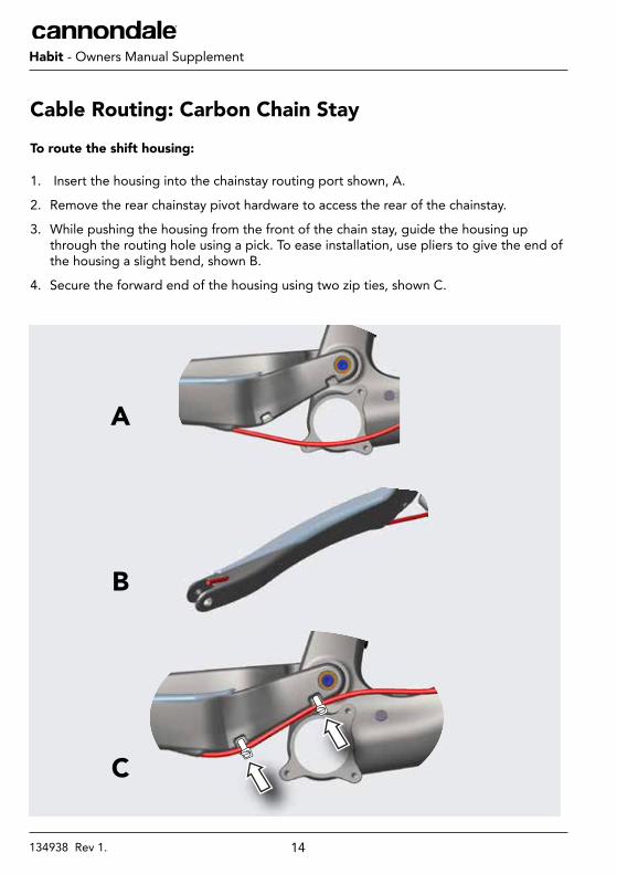
To route the shift housing:
1. Insert the housing into the chainstay routing port shown, A.
2. Remove the rear chainstay pivot hardware to access the rear of the chainstay.
3. While pushing the housing from the front of the chain stay, guide the housing up through the routing hole using a pick. To ease installation, use pliers to give the end of the housing a slight bend, shown B.
4. Secure the forward end of the housing using two zip ties, shown C.
Cable Routing: Carbon Chain Stay
A
B
C
15134938 Rev 1.
EnglishHabit - Owners Manual Supplement
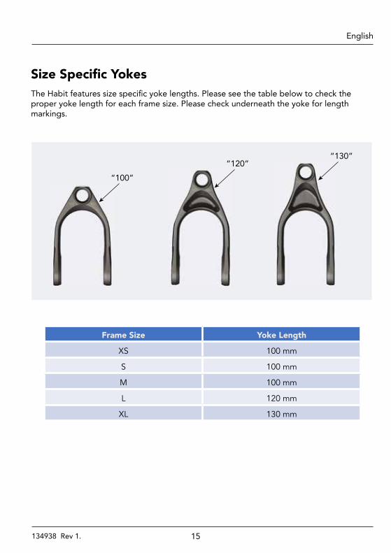
Size Specific YokesThe Habit features size specific yoke lengths. Please see the table below to check the proper yoke length for each frame size. Please check underneath the yoke for length markings.
“100”“120”
“130”
Frame Size Yoke Length
XS 100 mm
S 100 mm
M 100 mm
L 120 mm
XL 130 mm
16134938 Rev 1.
EnglishHabit - Owners Manual Supplement
NGLI-2
215 N·m
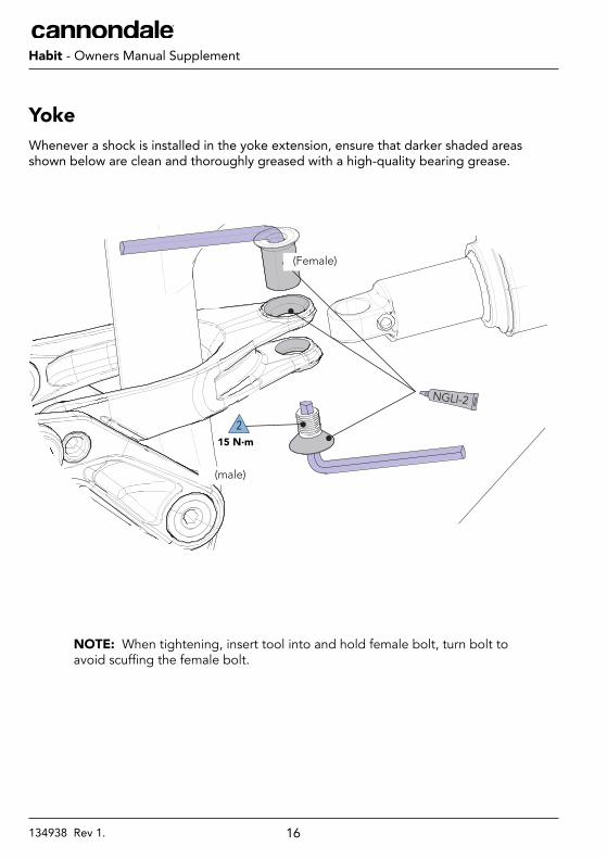
YokeWhenever a shock is installed in the yoke extension, ensure that darker shaded areas shown below are clean and thoroughly greased with a high-quality bearing grease.
NOTE: When tightening, insert tool into and hold female bolt, turn bolt to avoid scuffing the female bolt.
(Female)
(male)
17134938 Rev 1.
EnglishHabit - Owners Manual Supplement
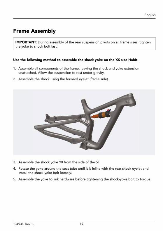
Frame Assembly
IMPORTANT: During assembly of the rear suspension pivots on all frame sizes, tighten the yoke to shock bolt last.
Use the following method to assemble the shock yoke on the XS size Habit:
1. Assemble all components of the frame, leaving the shock and yoke extension unattached. Allow the suspension to rest under gravity.
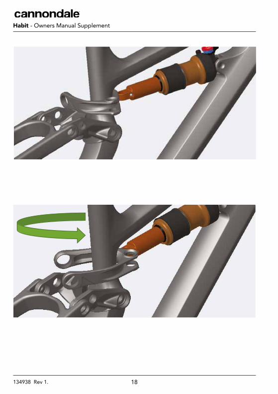
2. Assemble the shock using the forward eyelet (frame side).
3. Assemble the shock yoke 90 from the side of the ST.
4. Rotate the yoke around the seat tube until it is inline with the rear shock eyelet and install the shock-yoke bolt loosely.
5. Assemble the yoke to link hardware before tightening the shock-yoke bolt to torque.
18134938 Rev 1.
EnglishHabit - Owners Manual Supplement
19134938 Rev 1.
EnglishHabit - Owners Manual Supplement
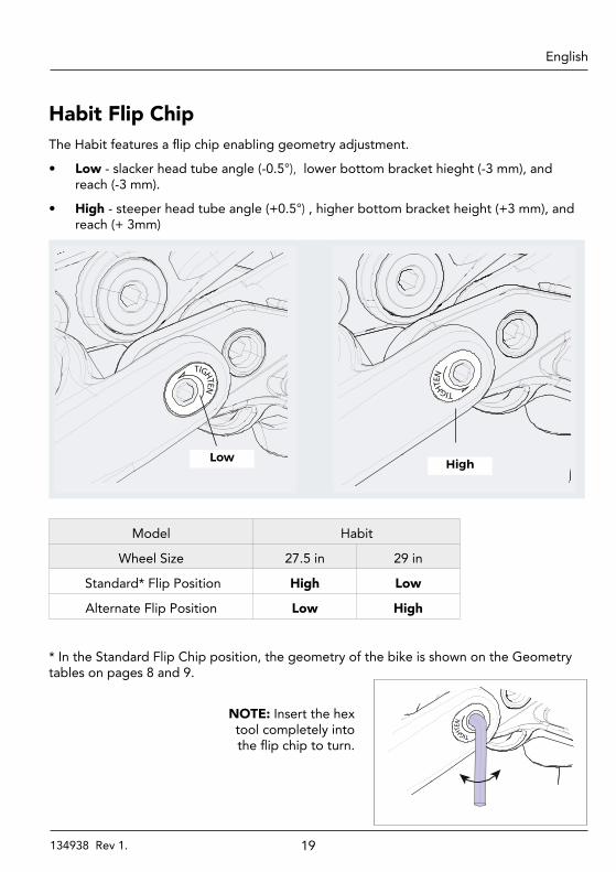
Habit Flip ChipThe Habit features a flip chip enabling geometry adjustment.
• Low - slacker head tube angle (-0.5°), lower bottom bracket hieght (-3 mm), and reach (-3 mm).
• High - steeper head tube angle (+0.5°) , higher bottom bracket height (+3 mm), and reach (+ 3mm)
TIGHTEN
TIGHTEN
High Low
Model Habit
Wheel Size 27.5 in 29 in
Standard* Flip Position High Low
Alternate Flip Position Low High
* In the Standard Flip Chip position, the geometry of the bike is shown on the Geometry tables on pages 8 and 9.
NOTE: Insert the hex tool completely into the flip chip to turn.
TIGHTEN
20134938 Rev 1.
EnglishHabit - Owners Manual Supplement
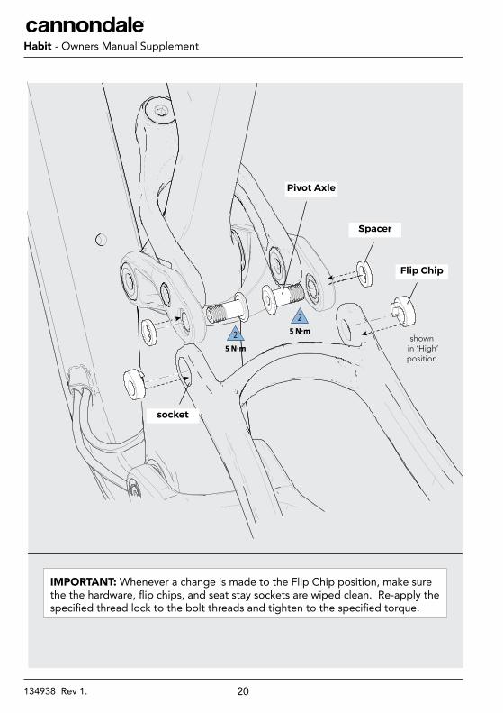
25 N·m2
5 N·m
Pivot Axle
Spacer
Flip Chip
IMPORTANT: Whenever a change is made to the Flip Chip position, make sure the the hardware, flip chips, and seat stay sockets are wiped clean. Re-apply the specified thread lock to the bolt threads and tighten to the specified torque.
shown in ‘High’ position
socket
21134938 Rev 1.
EnglishHabit - Owners Manual Supplement
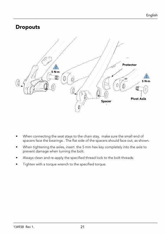
• When connecting the seat stays to the chain stay, make sure the small end of spacers face the bearings . The flat side of the spacers should face out, as shown.
• When tightening the axles, insert the 5 mm hex key completely into the axle to prevent damage when turning the bolt.
• Always clean and re-apply the specified thread lock to the bolt threads.
• Tighten with a torque wrench to the specified torque.
Dropouts
25 N·m
25 N·m
Pivot AxleSpacer
Protector
22134938 Rev 1.
EnglishHabit - Owners Manual Supplement
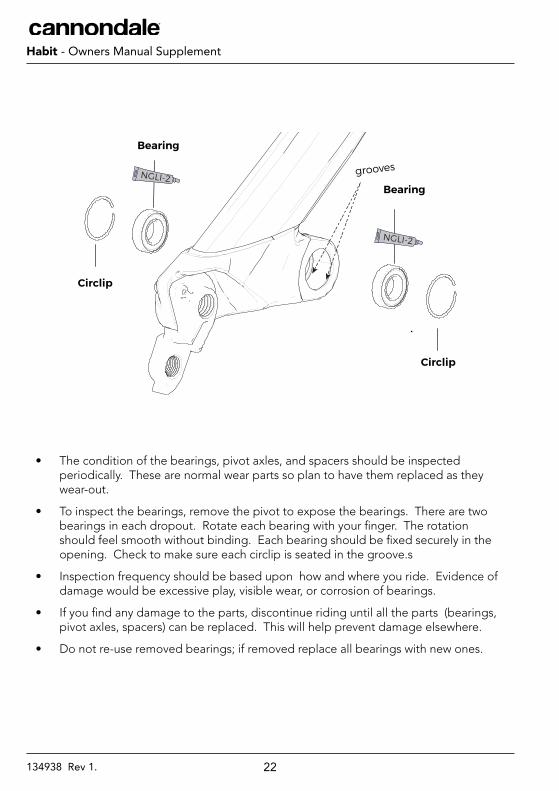
• The condition of the bearings, pivot axles, and spacers should be inspected periodically. These are normal wear parts so plan to have them replaced as they wear-out.
• To inspect the bearings, remove the pivot to expose the bearings. There are two bearings in each dropout. Rotate each bearing with your finger. The rotation should feel smooth without binding. Each bearing should be fixed securely in the opening. Check to make sure each circlip is seated in the groove.s
• Inspection frequency should be based upon how and where you ride. Evidence of damage would be excessive play, visible wear, or corrosion of bearings.
• If you find any damage to the parts, discontinue riding until all the parts (bearings, pivot axles, spacers) can be replaced. This will help prevent damage elsewhere.
• Do not re-use removed bearings; if removed replace all bearings with new ones.
NGLI-2
NGLI-2
Bearing
Circlip
Bearing
Circlip
grooves
23134938 Rev 1.
EnglishHabit - Owners Manual Supplement
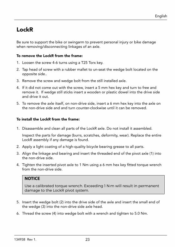
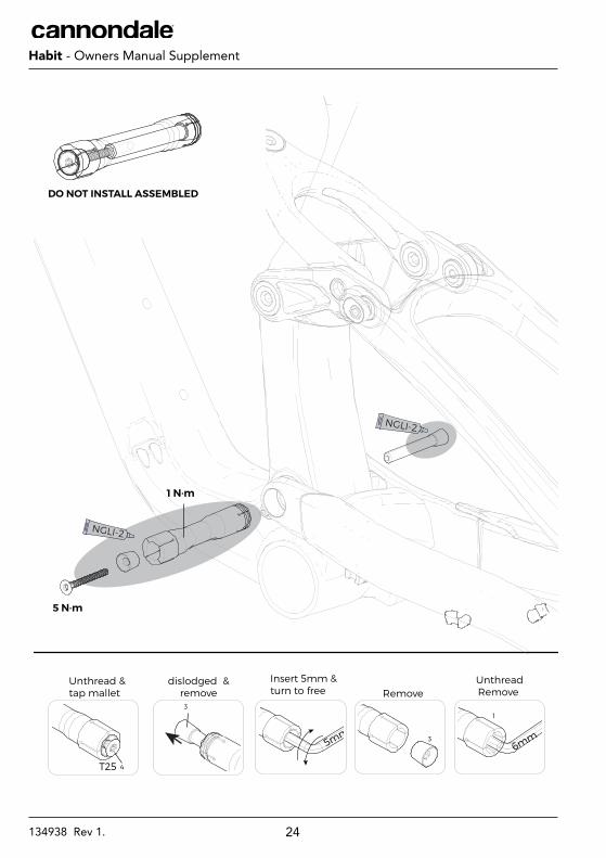
LockR
Be sure to support the bike or swingarm to prevent personal injury or bike damage when removing/disconnecting linkages of an axle.
To remove the LockR from the frame:
1. Loosen the screw 4-6 turns using a T25 Torx key.
2. Tap head of screw with a rubber mallet to un-seat the wedge bolt located on the opposite side..
3. Remove the screw and wedge bolt from the still installed axle.
4. If it did not come out with the screw, insert a 5 mm hex key and turn to free and remove it. If wedge still sticks insert a wooden or plastic dowel into the drive side and drive it out.
5. To remove the axle itself, on non-drive side, insert a 6 mm hex key into the axle on the non-drive side and and turn counter-clockwise until it can be removed.
To install the LockR from the frame:
1. Disassemble and clean all parts of the LockR axle. Do not install it assembled.
Inspect the parts for damage (burrs, scratches, deformity, wear). Replace the entire LockR assembly if any damage is found.
2. Apply a light coating of a high-quality bicycle bearing grease to all parts.
3. Align the linkage and bearing and insert the threaded end of the pivot axle (1) into the non-drive side.
4. Tighten the inserted pivot axle to 1 Nm using a 6 mm hex key fitted torque wrench from the non-drive side.
NOTICE
Use a calibrated torque wrench. Exceeding 1 N·m will result in permanent damage to the LockR pivot system.
5. Insert the wedge bolt (2) into the drive side of the axle and insert the small end of the wedge (3) into the non-drive side axle head.
6. Thread the screw (4) into wedge bolt with a wrench and tighten to 5.0 Nm.
24134938 Rev 1.
EnglishHabit - Owners Manual Supplement
Unthread &tap mallet
dislodged & remove
4
3
Insert 5mm &turn to free
5mm 3
Remove
6mm
UnthreadRemove
1
T25
NGLI-2
NGLI-2
5 N·m
1 N·m
DO NOT INSTALL ASSEMBLED
25134938 Rev 1.
EnglishHabit - Owners Manual Supplement
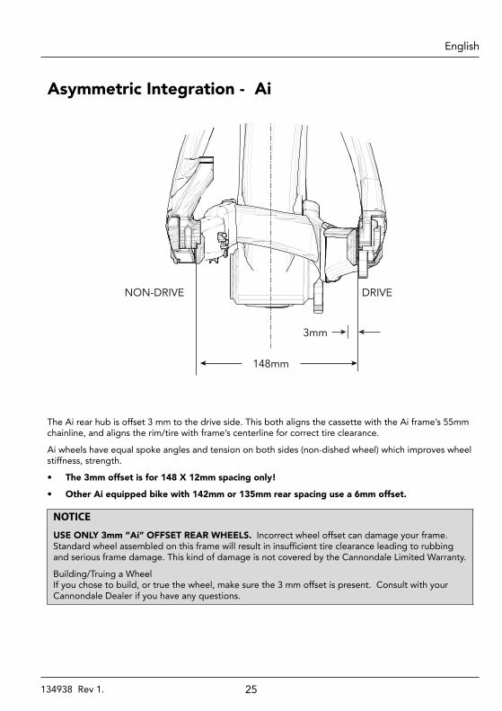
The Ai rear hub is offset 3 mm to the drive side. This both aligns the cassette with the Ai frame’s 55mm chainline, and aligns the rim/tire with frame’s centerline for correct tire clearance.
Ai wheels have equal spoke angles and tension on both sides (non-dished wheel) which improves wheel stiffness, strength.
• The 3mm offset is for 148 X 12mm spacing only!
• Other Ai equipped bike with 142mm or 135mm rear spacing use a 6mm offset.
NOTICE
USE ONLY 3mm “Ai” OFFSET REAR WHEELS. Incorrect wheel offset can damage your frame. Standard wheel assembled on this frame will result in insufficient tire clearance leading to rubbing and serious frame damage. This kind of damage is not covered by the Cannondale Limited Warranty.
Building/Truing a Wheel If you chose to build, or true the wheel, make sure the 3 mm offset is present. Consult with your Cannondale Dealer if you have any questions.
Asymmetric Integration - Ai
NON-DRIVE
3mm
148mm
DRIVE
26134938 Rev 1.
EnglishHabit - Owners Manual Supplement
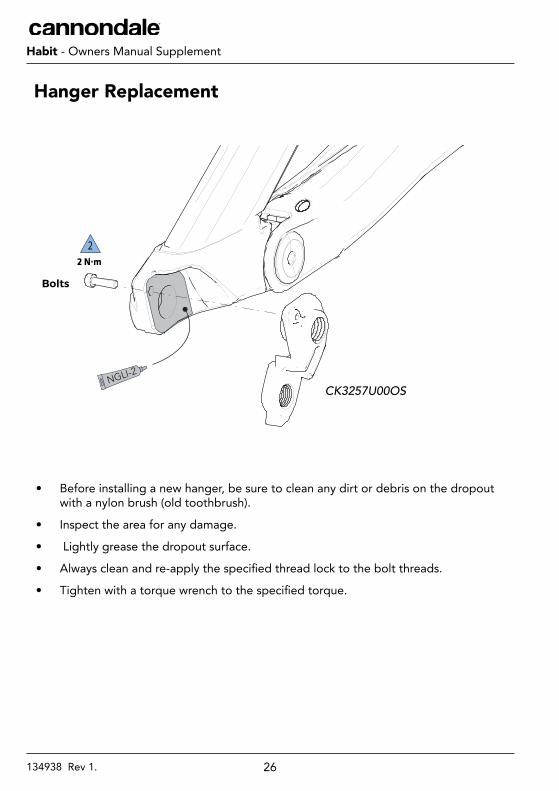
• Before installing a new hanger, be sure to clean any dirt or debris on the dropout with a nylon brush (old toothbrush).
• Inspect the area for any damage.
• Lightly grease the dropout surface.
• Always clean and re-apply the specified thread lock to the bolt threads.
• Tighten with a torque wrench to the specified torque.
NGLI-2
22 N·m
CK3257U00OS
Hanger Replacement
Bolts
27134938 Rev 1.
EnglishHabit - Owners Manual Supplement
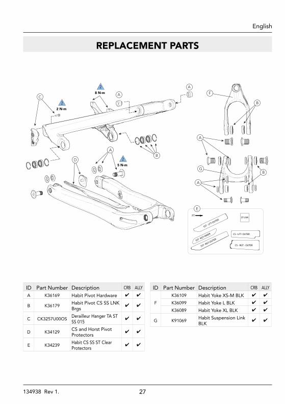
REPLACEMENT PARTS
P
25 N·m
34.9 mm
L
NGLI-2
1 N·m
5 N·m
M
ON
A
27 N·m
25 N·m
B
C
22 N·m
A
A
27 N·m
212 N·m
H
AA
I
I
K
F
B
BG
D
J
A
A
SST - LFT-OUTER
SST -RGT-INNER
SST -RGT-OUTER
CS - RGT - OUTER
CS - LFT- OUTER
ST-LNK
E
FT
E
28 N·m
215 N·m
NGLI-2
ID Part Number Description CRB ALLYA K36169 Habit Pivot Hardware ✔ ✔
B K36179 Habit Pivot CS SS LNK Brgs
✔ ✔
C CK3257U00OS Derailleur Hanger TA ST SS 015
✔ ✔
D K34129 CS and Horst Pivot Protectors
✔ ✔
E K34239 Habit CS SS ST Clear Protectors
✔ ✔
ID Part Number Description CRB ALLY
FK36109 Habit Yoke XS-M BLK ✔ ✔
K36099 Habit Yoke L BLK ✔ ✔
K36089 Habit Yoke XL BLK ✔ ✔
G K91069 Habit Suspension Link BLK
✔ ✔
28134938 Rev 1.
EnglishHabit - Owners Manual Supplement
P
25 N·m
34.9 mm
L
NGLI-2
1 N·m
5 N·m
M
ON
A
27 N·m
25 N·m
B
C
22 N·m
A
A
27 N·m
212 N·m
H
AA
I
I
K
F
B
BG
D
J
A
A
SST - LFT-OUTER
SST -RGT-INNER
SST -RGT-OUTER
CS - RGT - OUTER
CS - LFT- OUTER
ST-LNK
E
FT
E
28 N·m
215 N·m
NGLI-2
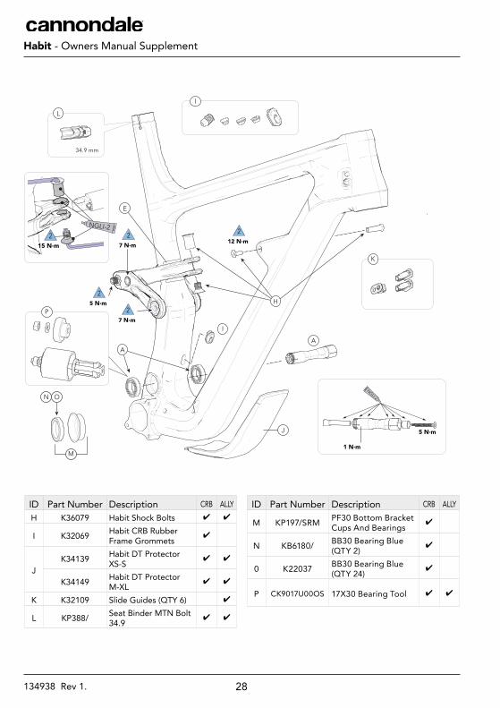
ID Part Number Description CRB ALLYH K36079 Habit Shock Bolts ✔ ✔
I K32069 Habit CRB Rubber Frame Grommets
✔
JK34139 Habit DT Protector
XS-S✔ ✔
K34149 Habit DT Protector M-XL
✔ ✔
K K32109 Slide Guides (QTY 6) ✔
L KP388/ Seat Binder MTN Bolt 34.9
✔ ✔
ID Part Number Description CRB ALLY
M KP197/SRM PF30 Bottom Bracket Cups And Bearings
✔
N KB6180/ BB30 Bearing Blue (QTY 2)
✔
0 K22037 BB30 Bearing Blue (QTY 24)
✔
P CK9017U00OS 17X30 Bearing Tool ✔ ✔
29134938 Rev 1.
EnglishHabit - Owners Manual Supplement
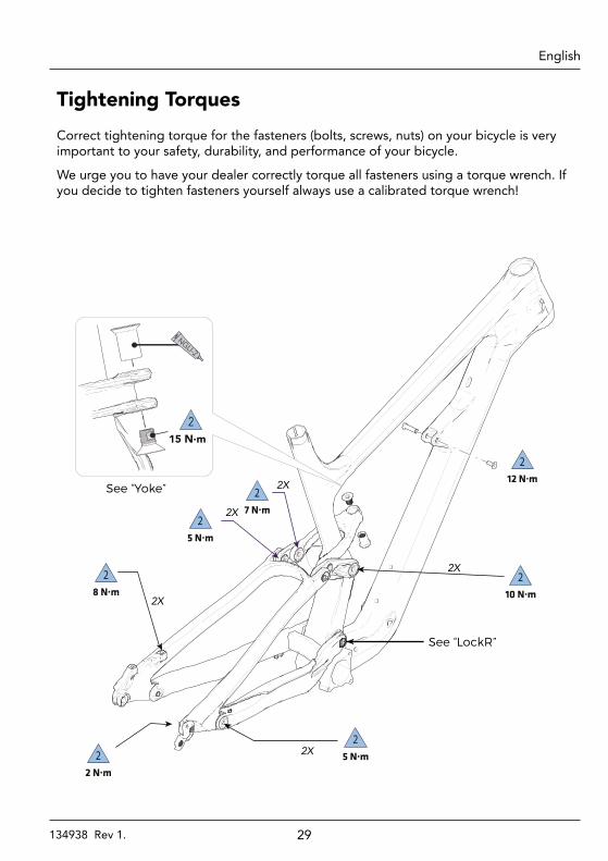
212 N·m
2X
See “LockR”
210 N·m
25 N·m
27 N·m
25 N·m2
2 N·m
28 N·m
2X
2X
2X
2X
215 N·m
NGLI-2
See “Yoke”
Correct tightening torque for the fasteners (bolts, screws, nuts) on your bicycle is very important to your safety, durability, and performance of your bicycle.
We urge you to have your dealer correctly torque all fasteners using a torque wrench. If you decide to tighten fasteners yourself always use a calibrated torque wrench!
Tightening Torques
30134938 Rev 1.
EnglishHabit - Owners Manual Supplement
MAINTENANCE
Any part of a poorly maintained bike can break or malfunction leading to an accident where you can be killed, severely injured or paralyzed.
Frequent checks are necessary to identify the problems that can lead to an accident. See “Inspect For Safety” in your Cannondale Bicycle Owners Manual.
The following table lists only supplemental maintenance items. Please consult your Cannondale Bicycle Owner’s Manual for more information on basic bike maintenance.
Item Frequency
Cable Routing - Make sure control cables are in place, undamaged and attached securely.
Frame Protection - Check the various frame protectors (downtube, headtube, chainstay, swingarm on your bike. Make sure they are in place and in good condition.
Before first ride
Damage Inspection - Clean and visually inspect entire bike frame/swing arm/linkage assembly for cracks or damage.
Before and after each ride
Check Tightening Torques - In addition to other component specific tightening torques for your bike. tighten according to the “Tightening Torques” information listed in this supplement.
Every few rides
Disassemble, clean, inspect, re-grease, replace worn or damaged parts in the following assemblies:
• Shock Link/Yoke • Pivot Axles • Frame Pivot Bearings
In wet, muddy, sandy conditions every 25 hrs.
In dry, conditions every 50 hrs.
Fork and Shock- Consult the manufacturer’s owner’s manual for maintenance requirements.
31134938 Rev 1.
EnglishHabit - Owners Manual Supplement
Use this page to write /record important information about your bike : (e.g. maintenance history, dealer contact information, settings, etc.)
NOTES

WWW.CANNONDALE.COM© 2019 Cycling Sports GroupHabit Owner’s Manual Supplement 134938 Rev. 1
CANNONDALE USACycling Sports Group, Inc.1 Cannondale Way, Wilton CT, 06897, USA1-800-726-BIKE (2453)www.cannondale.com
CANNONDALE EUROPECycling Sports Group Europe, B.V.Hanzepoort 27, 7575 DB, [email protected]
CANNONDALE UKCycling Sports GroupVantage Way, The Fulcrum, Poole, Dorset, BH12 4NU+44 (0)[email protected]
![CaseReport Habit Breaking Appliance for Multiple Corrections · Habit Breaking Appliance for Multiple Corrections ... removable habit breaking appliances [15, 16]. Hence, habit breaking](https://img.pdfslide.us/doc/110x75/5f15893424a8522d646af1b7/casereport-habit-breaking-appliance-for-multiple-corrections-habit-breaking-appliance.jpg)