Embed Size (px)
Citation preview
V1.0
CONTENTS
AERIAL IMAGING SOLUTION
02 INTRODUCTION03 ST24/ST12 OVERVIEW04 SPECIFICATIONS05 NOTICES AND WARNINGS06 GENERAL SAFETY PRECAUTIONS AND WARNINGS08 DISCLAIMER09 BATTERY WARNINGS AND USAGE GUIDELINES10 CHARGING THE LIPO FLIGHT BATTERY11 CHARGING THE LI-ION ST24 BATTERY11 CHARGING THE LI-ION ST12 BATTERY12 ASSEMBLING THE H92013 FLIGHT CONTROLS14 CONTROL RATE KNOB14 FLIGHT MODES17 INSTALLING THE GB603 GIMBAL AND CAMERA17 ATTACHING CGO4 GIMBAL CAMERA TO MULTICOPTER19 LED STATUS INDICATION20 PREPARING TO FLY20 FLYING21 COMPASS CALIBRATION23 BINDING (SINGLE MODE)24 CAMERA CONTROLS (SINGLE MODE)25 BINDING (TEAM MODE)27 CAMERA CONTROLS (TEAM MODE)
GROUND IMAGING SYSTEM
28 INTRODUCTION28 SPECIFICATIONS29 BATTERY WARNINGS AND USAGE GUIDELINES30 CHARGING THE BATTERY31 WARNINGS31 INSTALLING THE PROACTION™ BATTERY31 ATTACHING THE GB603 TO THE PROACTION™32 FOR THE SONY® α7 CAMERA32 ATTACHING CGO4 GIMBAL CAMERA TO PROACTION33 POWERING ON/OFF33 PROACTION™ CONTROLS34 Panasonic® GH4 CAMERA APP34 SONY® α7 CAMERA APP35 CGO4 GIMBAL CAMERA APP35 ATTACHING A MOBILE DEVICE TO THE PROACTION™35 WARRANTY INFORMATION36 OVERVIEW37 CERTIFICATION INFORMATION
AERIAL IMAGING SOLUTION
INTRODUCTION
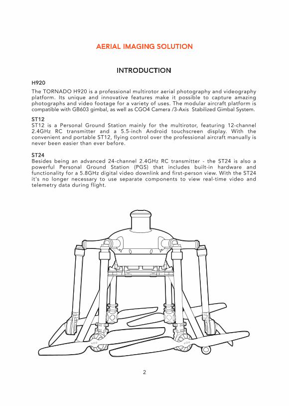
H920The TORNADO H920 is a professional multirotor aerial photography and videography platform. Its unique and innovative features make it possible to capture amazing photographs and video footage for a variety of uses. The modular aircraft platform is compatible with GB603 gimbal, as well as CGO4 Camera /3-Axis Stabilized Gimbal System.
ST12 ST12 is a Personal Ground Station mainly for the multirotor, featuring 12-channel 2.4GHz RC transmitter and a 5.5-inch Android touchscreen display. With the convenient and portable ST12, flying control over the professional aircraft manually is never been easier than ever before.
ST24Besides being an advanced 24-channel 2.4GHz RC transmitter - the ST24 is also a powerful Personal Ground Station (PGS) that includes built-in hardware and functionality for a 5.8GHz digital video downlink and first-person view. With the ST24 it's no longer necessary to use separate components to view real-time video and telemetry data during flight.
2
3
1
23
54
6
7
814
9
10
11
12
13
TS01
TS02
TS03
TS04
00 : 35 : 25 System Setting Channel Setting Model Select
9 25.0 V
TS05
TS06
TS07
TS08
GPS
VOL
FSK
WiFi
CHA
POS
CHA
POS
Pitch 0˚Roll 120˚
D/R 0˚20
10
10
0 0
0.0KPH
1 KM
0
-10
-10-20 -2020
0
20
10
10
00
0
-10
-20 -20 -10 20
0
15 16
15
6
7
8
9
10
2 34
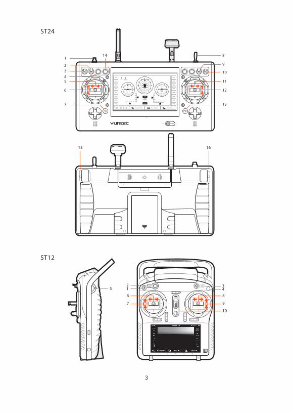
ST24
ST12

GB603 SINGLE OPERATOR MODE / ST241 Motor Start/Stop Button2 Gimbal Yaw Mode (Follow Mode/Global Mode)3 Gimbal Pitch Mode (Angle Mode/ Velocity Mode)4 Gimbal YAW Control5 Rudder/Yaw Control (Mode 2 and Mode 1)6 Throttle/Altitude Control ( Mode 2) Elevator/pitch control (Mode 1)7 Take Still Photo Button8 Landing Gear Switch9 GPS Switch10 Flight Mode Selection Switch11 Aileron/Roll Control (Mode 2 and Mode 1)12 Elevator/Pitch Control (Mode 2) Throttle/Altitude Control (Mode 1)13 Start/Stop Video Recording Button14 Proportional Control Rate Knob16 Gimbal Pitch Angle/Position Control Slider
GB603 TEAM MODE (Pilot) / ST12
1. Landing Gear Switch2. Motor Start/Stop Button3. Flight Mode Selection Switch4. GPS Knob5. Proportional Control Rate Slider6. Rudder/Yaw Control (for Mode 2 and Mode 1)7. Throttle/Altitude Control (for Mode 2) Elevator/Pitch Control (for Mode 1)8. Aileron/Roll Control (for Mode 2 and Mode 1)9. Elevator/Pitch Control (for Mode 2) Throttle/Altitude Control (for Mode 1)10 Power Switch GB603 TEAM MODE (Camera Man) / ST24
2 Gimbal Yaw Mode -FOLLOW (yaw can’t be controlled) -FOLLOW (yaw can be controlled) -Global 3 Gimbal Pitch Mode (Angle Mode/Velocity Mode)7 Still Photo Button11 Gimbal Yaw control stick12 Gimbal Pitch control stick (in Velocity mode)13 Start/Stop Video Recording Button16 Gimbal Pitch Angle/Position Control Slider in Gimbal Pitch Angle mode
CGO4 SINGLE OPERATOR MODE / ST24
1 Motor Start/Stop Button2 Gimbal Yaw Mode (Follow Mode/Global Mode)3 Gimbal Pitch Mode (Angle Mode/Velocity Mode)4 GIMBAL YAW Control5 Rudder/Yaw Control (Mode 2 and Mode 1)6 Throttle/Altitude Control (Mode 2) Elevator/pitch control (Mode 1)7 Take Still Photo Button8 Landing Gear Switch9 GPS Switch10 Flight Mode Selection Switch11 Aileron/Roll Control (Mode 2 and Mode 1)12 Elevator/Pitch Control (Mode 2) Throttle/Altitude Control (Mode 1)13 Start/Stop Video Recording Button14 Proportional Control Rate Knob15 CGO4 Zoom In/Out Control Slider16 Gimbal Pitch Angle/Position Control Slider
CGO4 TEAM MODE (Pilot) / ST12
1. Landing Gear Switch2. Motor Start/Stop Button3. Flight Mode Selection Switch4. GPS Knob5. Proportional Control Rate Slider6. Rudder/Yaw Control (for Mode 2 and Mode 1)7. Throttle/Altitude Control (for Mode 2) Elevator/Pitch Control (for Mode 1)8. Aileron/Roll Control (for Mode 2 and Mode 1)9. Elevator/Pitch Control (for Mode 2) Throttle/Altitude Control (for Mode 1)10 Power Switch
CGO4 TEAM MODE (Camera Man) / ST24
2 Gimbal Yaw Mode -FOLLOW (yaw can’t be controlled) -FOLLOW (yaw can be controlled) -Global3 Gimbal Pitch Mode (Angle Mode/Velocity Mode)7 Take Still Photo Button 11 Gimbal Yaw control stick12 Gimbal Pitch control stick13 Start/Stop Video Recording Button15 CGO4 ZOOM16 Gimbal Pitch Angle/Position Control Slider in Gimbal Pitch Angle mode
The default mode is Mode 2. The mode can be shifted in System Setting on the main interface of ST24 remote controller and Flight setting of ST12 remote controller.
SPECIFICATIONS
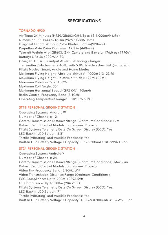
TORNADO H920Air Time: 24 Minutes (H920/GB603/GH4/3pcs 6S 4,000mAh LiPo)Dimension: 38.1x33.4x18.1in (969x849x461mm)Diagonal Length Without Rotor Blades: 36.2 in(920mm)Propeller/Main Rotor Diameter: 17.3 in (440mm)Take-off Weight with GB603, GH4 Camera and Battery: 176.0 oz (4990g)Battery: LiPo 6s 4000mAh 8CCharger: 100W 2 x output AC-DC Balancing ChargerTransmitter: 24-channel 2.4GHz with 5.8GHz video downlink (included)Flight Modes: Smart, Angle and Home ModesMaximum Flying Height (Absolute altitude): 4000m (13123 ft)Maximum Flying Height (Relative altitude): 122m(400 ft)Maximum Rotation Rate: 100°/sMaximum Roll Angle: 35°Maximum Horizontal Speed (GPS ON): 40km/hRadio Control Frequency Band: 2.4GHzOperating Temperature Range: ﹣10℃ to 50℃
ST12 PERSONAL GROUND STATIONOperating System:Android™Number of Channels: 12Control Transmission Distance/Range (Optimum Condition): 1kmRobust Radio Control Modulation: Yuneec ProtocolFlight Systems Telemetry Data On Screen Display (OSD): YesLED Backlit LCD Screen: 5.5”Tactile (Vibrating) and Audible Feedback: YesBuilt-In LiPo Battery Voltage / Capacity: 3.6V 5200mAh 18.72Wh Li-ion
ST24 PERSONAL GROUND STATIONOperating System: Android™Number of Channels: 24Control Transmission Distance/Range (Optimum Conditions): Max 2kmRobust Radio Control Modulation: Yuneec ProtocolVideo link Frequency Band: 5.8GHz WiFiVideo Transmission Distance/Range (Optimum Conditions):FCC Compliance: Up to 700m(2296.59ft)CE Compliance: Up to 300m (984.25 ft)Flight Systems Telemetry Data On Screen Display (OSD): YesLED Backlit LCD Screen: 7”Tactile (Vibrating) and Audible Feedback: YesBuilt-In LiPo Battery Voltage / Capacity: 1S 3.6V 8700mAh 31.32Wh Li-ion
NOTICES AND WARNINGS
IMPORTANT NOTE: All safety precautions and warnings, instructions, warranties and other collateral information is subject to change at the sole discretion of Yuneec. For the most up-to-date information please visit the corresponding product page at www.Yuneec.com or contact the nearest Yuneec office or authorized distributor.The following special language terms are used throughout the product literature to indicate various levels of potential harm when operating this product:NOTICE: Procedures, which if not properly followed, create a possibility of property damage and/or little to no possibility of injury.CAUTION: Procedures, which if not properly followed, create the probability of property damage and/or a possibility of serious injury.WARNING: Procedures, which if not properly followed, create the probability of property damage, collateral damage and/or serious injury or create a high probability of superficial injury.WARNING: Read the ENTIRE quick start guide and instruction manual to become familiar with the features of the product before operating. Failure to operate the product correctly can result in damage to the product, property and/or cause serious injury.WARNING: This is a sophisticated consumer product. It must be operated with caution and common sense, and requires some basic mechanical ability.Failure to operate this product in a safe and responsible manner could result in damage to the product, property and/or cause serious injury. This product is not intended for use by children without direct adult supervision. Do not use with incompatible components or alter this product in any way outside of the instructions provided by Yuneec. The quick start guide and instruction manual contain instructions for safety, operation and maintenance. It is essential to read and follow all the instructions and warnings prior to assembly, setup and/or use in order to operate the product correctly and avoid damage or serious injury.AGE RECOMMENDATION: NOT FOR CHILDREN UNDER 14 YEARS. THIS IS NOT A TOY.
GENERAL SAFETY PRECAUTIONS AND WARNINGS
WARNING: Failure to use this product in the intended manner as described in the quick start guide and instruction manual can result in damage to the product, property and/or cause serious injury. A Radio Controlled (RC) multirotor aircraft, APV platform, drone, etc. is not a toy! If misused it can cause serious bodily harm and damage to property.WARNING: As the user of this product you are solely and entirely responsible for operating it in a manner that does not endanger yourself and others or result in damage to the product or the property of others.• Keep your hands, face and other parts of your body away from the spinning propellers/rotor blades and other moving parts at all times. Keep items that could impact or become entangled away from the propellers/rotor blades including debris, parts, tools, loose clothing, etc.• Always operate your aircraft in open areas that are free from people, vehicles and other obstructions. Never fly near or above crowds, airports or buildings.• To ensure proper operation and safe flight performance never attempt to operate your aircraft nearby buildings or other obstructions that do not offer a clear view of the sky and can restrict GPS reception.• Do not attempt to operate your aircraft in areas with potential magnetic and/or radio interference including areas nearby broadcast towers, power transmission stations, high voltage power lines, electrical storms, etc.• Always keep a safe distance in all directions around your aircraft to avoid collisions and/or injury. This aircraft is controlled by a radio signal subject to interference from many sources outside your control. Interference can cause momentary loss of control.• To ensure proper and safe operation of the automatic landing function in Home Mode you must start the motors with the aircraft in a position that has at least 10 feet (approximately 3 meters) of clear and open space around it and achieve a proper GPS lock.• Do not attempt to operate your aircraft with any worn and/or damaged components, parts, etc. (including, but not limited to, damaged propellers/rotor blades, old batteries, etc.).• Never operate your aircraft in poor or severe weather conditions including heavy winds, precipitation, lightning, etc.• Always operate your aircraft starting with a fully charged battery. Always land as soon as possible after the first level low voltage battery warning or land immediately after the second level low voltage battery warning (as indicated by the vibrations and audible alerts from the transmitter/personal ground station).• Always operate your aircraft when the voltage of the battery in the transmitter/personal ground station is in a safe range (as indicated by the battery charge status icon on the screen of the transmitter/personal ground station).• Always keep the aircraft in clear line of sight and under control, and keep the transmitter/personal ground station powered on while the aircraft is powered on.• Always move the throttle control stick down fully and turn off the motors in the event the propellers/rotor blades come into contact with any objects.• Always allow components and parts to cool after use before touching them and flying again.• Always remove batteries after use and store/transport them per the corresponding guidelines.• Avoid water exposure to all electronic components, parts, etc. not specifically designed and protected for use in water. Moisture causes damage to electronic components and parts.• Never place any portion of the aircraft or any related accessories, components or parts in your mouth as doing so could cause serious injury or even death.• Always keep chemicals, small parts and electronic components out of the reach of children.• Carefully follow the instructions and warnings included with this aircraft and any related accessories, components or parts (including, but not limited to, chargers, rechargeable batteries, etc.).CAUTION: The electronic speed controls (ESCs) installed in the TORNADO are not compatible with any other product, and the TORNADO is not compatible with any other ESCs. Use of any other ESCs in the TORNADO will cause a crash, which may result in damage to the product, property and/or cause serious injury.
4
NOTICES AND WARNINGS
IMPORTANT NOTE: All safety precautions and warnings, instructions, warranties and other collateral information is subject to change at the sole discretion of Yuneec. For the most up-to-date information please visit the corresponding product page at www.Yuneec.com or contact the nearest Yuneec office or authorized distributor.The following special language terms are used throughout the product literature to indicate various levels of potential harm when operating this product:NOTICE: Procedures, which if not properly followed, create a possibility of property damage and/or little to no possibility of injury.CAUTION: Procedures, which if not properly followed, create the probability of property damage and/or a possibility of serious injury.WARNING: Procedures, which if not properly followed, create the probability of property damage, collateral damage and/or serious injury or create a high probability of superficial injury.WARNING: Read the ENTIRE quick start guide and instruction manual to become familiar with the features of the product before operating. Failure to operate the product correctly can result in damage to the product, property and/or cause serious injury.WARNING: This is a sophisticated consumer product. It must be operated with caution and common sense, and requires some basic mechanical ability.Failure to operate this product in a safe and responsible manner could result in damage to the product, property and/or cause serious injury. This product is not intended for use by children without direct adult supervision. Do not use with incompatible components or alter this product in any way outside of the instructions provided by Yuneec. The quick start guide and instruction manual contain instructions for safety, operation and maintenance. It is essential to read and follow all the instructions and warnings prior to assembly, setup and/or use in order to operate the product correctly and avoid damage or serious injury.AGE RECOMMENDATION: NOT FOR CHILDREN UNDER 14 YEARS. THIS IS NOT A TOY.
GENERAL SAFETY PRECAUTIONS AND WARNINGS
WARNING: Failure to use this product in the intended manner as described in the quick start guide and instruction manual can result in damage to the product, property and/or cause serious injury. A Radio Controlled (RC) multirotor aircraft, APV platform, drone, etc. is not a toy! If misused it can cause serious bodily harm and damage to property.WARNING: As the user of this product you are solely and entirely responsible for operating it in a manner that does not endanger yourself and others or result in damage to the product or the property of others.• Keep your hands, face and other parts of your body away from the spinning propellers/rotor blades and other moving parts at all times. Keep items that could impact or become entangled away from the propellers/rotor blades including debris, parts, tools, loose clothing, etc.• Always operate your aircraft in open areas that are free from people, vehicles and other obstructions. Never fly near or above crowds, airports or buildings.• To ensure proper operation and safe flight performance never attempt to operate your aircraft nearby buildings or other obstructions that do not offer a clear view of the sky and can restrict GPS reception.• Do not attempt to operate your aircraft in areas with potential magnetic and/or radio interference including areas nearby broadcast towers, power transmission stations, high voltage power lines, electrical storms, etc.• Always keep a safe distance in all directions around your aircraft to avoid collisions and/or injury. This aircraft is controlled by a radio signal subject to interference from many sources outside your control. Interference can cause momentary loss of control.• To ensure proper and safe operation of the automatic landing function in Home Mode you must start the motors with the aircraft in a position that has at least 10 feet (approximately 3 meters) of clear and open space around it and achieve a proper GPS lock.• Do not attempt to operate your aircraft with any worn and/or damaged components, parts, etc. (including, but not limited to, damaged propellers/rotor blades, old batteries, etc.).• Never operate your aircraft in poor or severe weather conditions including heavy winds, precipitation, lightning, etc.• Always operate your aircraft starting with a fully charged battery. Always land as soon as possible after the first level low voltage battery warning or land immediately after the second level low voltage battery warning (as indicated by the vibrations and audible alerts from the transmitter/personal ground station).• Always operate your aircraft when the voltage of the battery in the transmitter/personal ground station is in a safe range (as indicated by the battery charge status icon on the screen of the transmitter/personal ground station).• Always keep the aircraft in clear line of sight and under control, and keep the transmitter/personal ground station powered on while the aircraft is powered on.• Always move the throttle control stick down fully and turn off the motors in the event the propellers/rotor blades come into contact with any objects.• Always allow components and parts to cool after use before touching them and flying again.• Always remove batteries after use and store/transport them per the corresponding guidelines.• Avoid water exposure to all electronic components, parts, etc. not specifically designed and protected for use in water. Moisture causes damage to electronic components and parts.• Never place any portion of the aircraft or any related accessories, components or parts in your mouth as doing so could cause serious injury or even death.• Always keep chemicals, small parts and electronic components out of the reach of children.• Carefully follow the instructions and warnings included with this aircraft and any related accessories, components or parts (including, but not limited to, chargers, rechargeable batteries, etc.).CAUTION: The electronic speed controls (ESCs) installed in the TORNADO are not compatible with any other product, and the TORNADO is not compatible with any other ESCs. Use of any other ESCs in the TORNADO will cause a crash, which may result in damage to the product, property and/or cause serious injury.
5
NOTICES AND WARNINGS
IMPORTANT NOTE: All safety precautions and warnings, instructions, warranties and other collateral information is subject to change at the sole discretion of Yuneec. For the most up-to-date information please visit the corresponding product page at www.Yuneec.com or contact the nearest Yuneec office or authorized distributor.The following special language terms are used throughout the product literature to indicate various levels of potential harm when operating this product:NOTICE: Procedures, which if not properly followed, create a possibility of property damage and/or little to no possibility of injury.CAUTION: Procedures, which if not properly followed, create the probability of property damage and/or a possibility of serious injury.WARNING: Procedures, which if not properly followed, create the probability of property damage, collateral damage and/or serious injury or create a high probability of superficial injury.WARNING: Read the ENTIRE quick start guide and instruction manual to become familiar with the features of the product before operating. Failure to operate the product correctly can result in damage to the product, property and/or cause serious injury.WARNING: This is a sophisticated consumer product. It must be operated with caution and common sense, and requires some basic mechanical ability.Failure to operate this product in a safe and responsible manner could result in damage to the product, property and/or cause serious injury. This product is not intended for use by children without direct adult supervision. Do not use with incompatible components or alter this product in any way outside of the instructions provided by Yuneec. The quick start guide and instruction manual contain instructions for safety, operation and maintenance. It is essential to read and follow all the instructions and warnings prior to assembly, setup and/or use in order to operate the product correctly and avoid damage or serious injury.AGE RECOMMENDATION: NOT FOR CHILDREN UNDER 14 YEARS. THIS IS NOT A TOY.
GENERAL SAFETY PRECAUTIONS AND WARNINGS
WARNING: Failure to use this product in the intended manner as described in the quick start guide and instruction manual can result in damage to the product, property and/or cause serious injury. A Radio Controlled (RC) multirotor aircraft, APV platform, drone, etc. is not a toy! If misused it can cause serious bodily harm and damage to property.WARNING: As the user of this product you are solely and entirely responsible for operating it in a manner that does not endanger yourself and others or result in damage to the product or the property of others.• Keep your hands, face and other parts of your body away from the spinning propellers/rotor blades and other moving parts at all times. Keep items that could impact or become entangled away from the propellers/rotor blades including debris, parts, tools, loose clothing, etc.• Always operate your aircraft in open areas that are free from people, vehicles and other obstructions. Never fly near or above crowds, airports or buildings.• To ensure proper operation and safe flight performance never attempt to operate your aircraft nearby buildings or other obstructions that do not offer a clear view of the sky and can restrict GPS reception.• Do not attempt to operate your aircraft in areas with potential magnetic and/or radio interference including areas nearby broadcast towers, power transmission stations, high voltage power lines, electrical storms, etc.• Always keep a safe distance in all directions around your aircraft to avoid collisions and/or injury. This aircraft is controlled by a radio signal subject to interference from many sources outside your control. Interference can cause momentary loss of control.• To ensure proper and safe operation of the automatic landing function in Home Mode you must start the motors with the aircraft in a position that has at least 10 feet (approximately 3 meters) of clear and open space around it and achieve a proper GPS lock.• Do not attempt to operate your aircraft with any worn and/or damaged components, parts, etc. (including, but not limited to, damaged propellers/rotor blades, old batteries, etc.).• Never operate your aircraft in poor or severe weather conditions including heavy winds, precipitation, lightning, etc.• Always operate your aircraft starting with a fully charged battery. Always land as soon as possible after the first level low voltage battery warning or land immediately after the second level low voltage battery warning (as indicated by the vibrations and audible alerts from the transmitter/personal ground station).• Always operate your aircraft when the voltage of the battery in the transmitter/personal ground station is in a safe range (as indicated by the battery charge status icon on the screen of the transmitter/personal ground station).• Always keep the aircraft in clear line of sight and under control, and keep the transmitter/personal ground station powered on while the aircraft is powered on.• Always move the throttle control stick down fully and turn off the motors in the event the propellers/rotor blades come into contact with any objects.• Always allow components and parts to cool after use before touching them and flying again.• Always remove batteries after use and store/transport them per the corresponding guidelines.• Avoid water exposure to all electronic components, parts, etc. not specifically designed and protected for use in water. Moisture causes damage to electronic components and parts.• Never place any portion of the aircraft or any related accessories, components or parts in your mouth as doing so could cause serious injury or even death.• Always keep chemicals, small parts and electronic components out of the reach of children.• Carefully follow the instructions and warnings included with this aircraft and any related accessories, components or parts (including, but not limited to, chargers, rechargeable batteries, etc.).CAUTION: The electronic speed controls (ESCs) installed in the TORNADO are not compatible with any other product, and the TORNADO is not compatible with any other ESCs. Use of any other ESCs in the TORNADO will cause a crash, which may result in damage to the product, property and/or cause serious injury.
6
THE TORNADO H920 RTF CONTENTS
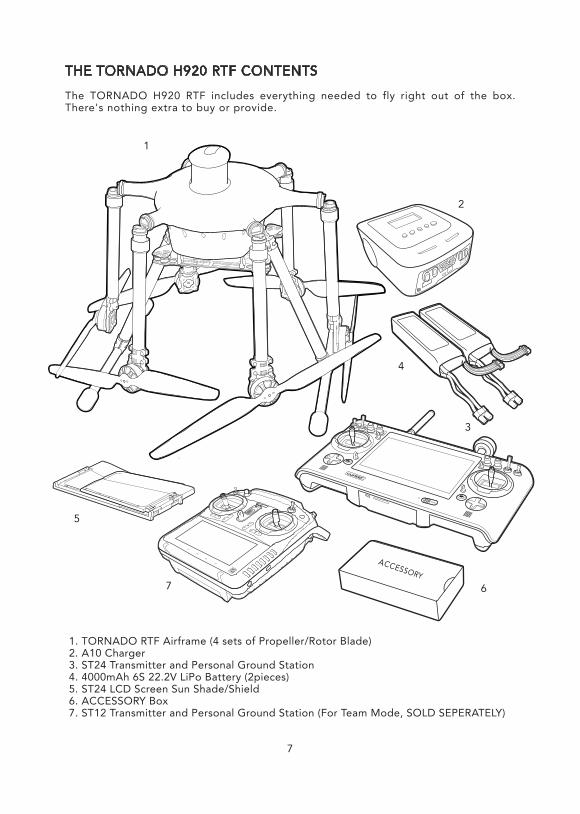
The TORNADO H920 RTF includes everything needed to fly right out of the box. There's nothing extra to buy or provide.
NOTICES AND WARNINGS
IMPORTANT NOTE: All safety precautions and warnings, instructions, warranties and other collateral information is subject to change at the sole discretion of Yuneec. For the most up-to-date information please visit the corresponding product page at www.Yuneec.com or contact the nearest Yuneec office or authorized distributor.The following special language terms are used throughout the product literature to indicate various levels of potential harm when operating this product:NOTICE: Procedures, which if not properly followed, create a possibility of property damage and/or little to no possibility of injury.CAUTION: Procedures, which if not properly followed, create the probability of property damage and/or a possibility of serious injury.WARNING: Procedures, which if not properly followed, create the probability of property damage, collateral damage and/or serious injury or create a high probability of superficial injury.WARNING: Read the ENTIRE quick start guide and instruction manual to become familiar with the features of the product before operating. Failure to operate the product correctly can result in damage to the product, property and/or cause serious injury.WARNING: This is a sophisticated consumer product. It must be operated with caution and common sense, and requires some basic mechanical ability.Failure to operate this product in a safe and responsible manner could result in damage to the product, property and/or cause serious injury. This product is not intended for use by children without direct adult supervision. Do not use with incompatible components or alter this product in any way outside of the instructions provided by Yuneec. The quick start guide and instruction manual contain instructions for safety, operation and maintenance. It is essential to read and follow all the instructions and warnings prior to assembly, setup and/or use in order to operate the product correctly and avoid damage or serious injury.AGE RECOMMENDATION: NOT FOR CHILDREN UNDER 14 YEARS. THIS IS NOT A TOY.
GENERAL SAFETY PRECAUTIONS AND WARNINGS
WARNING: Failure to use this product in the intended manner as described in the quick start guide and instruction manual can result in damage to the product, property and/or cause serious injury. A Radio Controlled (RC) multirotor aircraft, APV platform, drone, etc. is not a toy! If misused it can cause serious bodily harm and damage to property.WARNING: As the user of this product you are solely and entirely responsible for operating it in a manner that does not endanger yourself and others or result in damage to the product or the property of others.• Keep your hands, face and other parts of your body away from the spinning propellers/rotor blades and other moving parts at all times. Keep items that could impact or become entangled away from the propellers/rotor blades including debris, parts, tools, loose clothing, etc.• Always operate your aircraft in open areas that are free from people, vehicles and other obstructions. Never fly near or above crowds, airports or buildings.• To ensure proper operation and safe flight performance never attempt to operate your aircraft nearby buildings or other obstructions that do not offer a clear view of the sky and can restrict GPS reception.• Do not attempt to operate your aircraft in areas with potential magnetic and/or radio interference including areas nearby broadcast towers, power transmission stations, high voltage power lines, electrical storms, etc.• Always keep a safe distance in all directions around your aircraft to avoid collisions and/or injury. This aircraft is controlled by a radio signal subject to interference from many sources outside your control. Interference can cause momentary loss of control.• To ensure proper and safe operation of the automatic landing function in Home Mode you must start the motors with the aircraft in a position that has at least 10 feet (approximately 3 meters) of clear and open space around it and achieve a proper GPS lock.• Do not attempt to operate your aircraft with any worn and/or damaged components, parts, etc. (including, but not limited to, damaged propellers/rotor blades, old batteries, etc.).• Never operate your aircraft in poor or severe weather conditions including heavy winds, precipitation, lightning, etc.• Always operate your aircraft starting with a fully charged battery. Always land as soon as possible after the first level low voltage battery warning or land immediately after the second level low voltage battery warning (as indicated by the vibrations and audible alerts from the transmitter/personal ground station).• Always operate your aircraft when the voltage of the battery in the transmitter/personal ground station is in a safe range (as indicated by the battery charge status icon on the screen of the transmitter/personal ground station).• Always keep the aircraft in clear line of sight and under control, and keep the transmitter/personal ground station powered on while the aircraft is powered on.• Always move the throttle control stick down fully and turn off the motors in the event the propellers/rotor blades come into contact with any objects.• Always allow components and parts to cool after use before touching them and flying again.• Always remove batteries after use and store/transport them per the corresponding guidelines.• Avoid water exposure to all electronic components, parts, etc. not specifically designed and protected for use in water. Moisture causes damage to electronic components and parts.• Never place any portion of the aircraft or any related accessories, components or parts in your mouth as doing so could cause serious injury or even death.• Always keep chemicals, small parts and electronic components out of the reach of children.• Carefully follow the instructions and warnings included with this aircraft and any related accessories, components or parts (including, but not limited to, chargers, rechargeable batteries, etc.).CAUTION: The electronic speed controls (ESCs) installed in the TORNADO are not compatible with any other product, and the TORNADO is not compatible with any other ESCs. Use of any other ESCs in the TORNADO will cause a crash, which may result in damage to the product, property and/or cause serious injury.
7
1. TORNADO RTF Airframe (4 sets of Propeller/Rotor Blade)2. A10 Charger3. ST24 Transmitter and Personal Ground Station4. 4000mAh 6S 22.2V LiPo Battery (2pieces)5. ST24 LCD Screen Sun Shade/Shield6. ACCESSORY Box7. ST12 Transmitter and Personal Ground Station (For Team Mode, SOLD SEPERATELY)
1
2
3
4
7
5
6
DISCLAIMER
Yuneec Electric Aviation cannot be held liable for any damage, injury or for use of the product in violation with legal regulations, especially in the following circumstances:Damage and/or injury as well violation of legal regulations resulting from a failure to comply with the operating instructions or the instructions at www.yuneec.com, product information, user manual and other legally binding information.Damage and/or injury as well violation of legal regulations brought about by the influence of alcohol, drugs, medication or mother narcotics which may impact on the concentration of the user. The same applies to illnesses effecting the concentration of the user (dizziness, tiredness, nausea etc.) or other factors compromising mental and physical capabilities. Intentionally caused damage, injury or violation of legal regulations.Any request for compensation caused by an accident resulting from use of the product.Damage and/or injury as well as violation of legal regulations caused by use of the product in a no-fly zone, e.g. next to an airfield, above a motorway or a natural conservation area. Malfunction of the product caused by retrofitting or replacement with components which did not come from Yuneec Electric Aviation.Damage and/or injury caused by the use of replica parts (non-original parts).Damage and/or injury as well as violation of legal regulations caused by incorrect operation or misjudgment.Damage and/or injury caused by damaged spare parts or not using original Yuneec Electric Aviation spare parts.Damage and/or injury as well as violation of legal regulations caused by ignoring the low voltage battery warning.Damage and/or injury caused by knowingly and negligibly flying with a damaged model or one which is unfit to fly, e.g. due to dirt, water penetration, coarse particles, oil or a model which has not been correctly or completely assembled or if the main components exhibit visible damage, defects or missing parts.Damage and/or injury as well as violation of legal regulations caused by operating the model in a magnetic field (e.g. high voltage lines, electricity/transformer stations, radio towers, mobile phone masts etc.), a strong wireless signal environment, no-fly zones, poor visibility and in the event of vision impairments or other impacts on the pilot which are left unchecked etc...Damage and/or injury brought about through a violation of the legal regulations for operating the model, in unsuitable weather conditions, e.g. rain, wind, snow, hail, storms, hurricanes etc.Damage and/or injury as well as violation of legal regulations caused by force majeure, e.g. collision, fire, explosion, flooding, tsunami, landslide, avalanche, earthquake or other forces of nature.Damage and/or injury as well as violation of legal regulations caused by the illegal or immoral use of the model, e.g. capturing videos or recording data which infringes upon/harms the privacy of other people.Damage and/or injury as well as violation of legal regulations caused by incorrect use of the batteries, protection systems, chargers or aircraft.Consequential damage caused by the incorrect operation of any kind of system components and accessory parts, especially memory cards, whereby image or video material from the camera can become defect.Any non-compliance with legal obligations, personal injury, material damage and environmental damage caused by use and a failure to comply with the local laws and regulations.Damage and/or injury as well as violation of legal regulations caused by hazardous use without sufficient practical experience.Damage and/or injury as well as violation of legal regulations caused by flying in legally defined no-fly zones. Further losses which do not fall within the scope of use defined by Yuneec Electric Aviation as improper.This product is designed for both professional use and personal, private use. The national and international laws and regulations in force as the time of take off must be adhered to.
8
LIPO BATTERY WARNINGS AND USAGE GUIDELINES
WARNING: Lithium Polymer (LiPo) batteries are significantly more volatile than alkaline, NiCd or NiMH batteries. All instructions and warnings must be followed exactly to prevent property damage and/or serious injury as the mishandling of LiPo batteries can result in fire. By handling, charging or using the included LiPo battery you assume all risks associated with LiPo batteries. If you do not agree with these conditions please return the complete product in new, unused condition to the place of purchase immediately.• You must always charge the LiPo battery in a safe, well-ventilated area away from flammable materials.• Never charge the LiPo battery unattended at any time. When charging the battery you must always remain in constant observation to monitor the charging process and react immediately to any potential problems that may occur.• After flying/discharging the LiPo battery you must allow it to cool to ambient/room temperature before recharging.• To charge the LiPo battery you must use only the included charger or a suitably compatible LiPo battery charger. Failure to do so may result in a fire causing property damage and/or serious injury.• If at any time the LiPo battery begins to balloon or swell, discontinue charging or discharging immediately. Quickly and safely disconnect the battery, then place it in a safe, open area away from flammable materials to observe it for at least 15 minutes. Continuing to charge or discharge a battery that has begun to balloon or swell can result in a fire. A battery that has ballooned or swollen even a small amount must be removed from service completely.• Do not over-discharge the LiPo battery. Discharging the battery too low can cause damage to the battery resulting inreduced power, flight duration or failure of the battery entirely. LiPo cells should not be discharged to below 3.0V each under load.• Store the LiPo battery at room temperature and in a dry area for best results.• When charging, transporting or temporarily storing the LiPo battery the temperature range should be from approximately 40–120° F (5–49° C). Do not store the battery or aircraft in a hot garage, car or direct sunlight. If stored in a hot garage or car the battery can be damaged or even catch fire.• Never leave batteries, chargers and power supplies unattended during use.• Never attempt to charge low voltage, ballooned/swollen, damaged or wet batteries.• Never allow children under 14 years of age to charge batteries.• Never charge a battery if any of the wire leads have been damaged or shorted.• Never attempt to disassemble the battery, charger or power supply.• Never drop batteries, chargers or power supplies.• Always inspect the battery, charger and power supply before charging.• Always ensure correct polarity before connecting batteries, chargers and power supplies.• Always disconnect the battery after charging.• Always terminate all processes if the battery, charger or power supply malfunctions.IMPORTANT NOTE: It’s safer and better for the longevity of the battery to store it only partially charged for any length of time. Storing the battery approximately 50% charged is typically best, however, it will take some careful management of the charge time and the use of a volt meter to achieve this voltage. If you have the equipment and skills to achieve the 50% charge level for storage it is recommended. If not, simply be sure to not store the battery fully charged whenever possible.In fact, as long as the battery will be stored at approximately room temperature and for no more than a few weeks before the next use, it may be best to store the battery in the discharged state after the last flight (as long as the battery was not over-discharged on the last flight).
9
CHARGING THE LIPO FLIGHT BATTERY
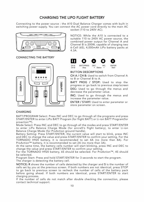
Connecting to the power source : the A10 Dual Balance Charger comes with built in switching power supply. You can connect the AC power cord directly to the main AC
socket (110 to 240V AC).
NOTICE: While the A10 is connected to a suitable 110 to 240V AC power source, the combined power output for Channel A and Channel B is 200W, capable of charging two 6-Cell (6S), 4,000mAh LiPo battery packs at 4.3A.
CONNECTING THE BATTERY
CHARGINGBATT/PROGRAM Select: Press INC and DEC to go through all the programs and press START/ENTER to enter LiPo BATT Program (for flight BATT) or Li-ion BATT Program(for proaction™).Mode Select: Press INC and DEC to go through all the modes and press START/ENTER to enter LiPo Balance Charge Mode (for aircraft’s flight battery), to enter Li-ion Balance Charge Mode (for ProAction ground handle).Battery Setting: Press START/ENTER, the current value will start to blink, press INC and DEC to change the value and press START/ENTER to confirm your setting. For the TORNADO H920 battery, it is recommended to set 4A (no more than 8A). For ProAction™ battery, it is recommended to set 2A (no more than 3A).At the same time, the battery cells number will start blinking, press INC and DEC to change the value and press START/ENTER to confirm your setting.For the TORNADO H920 battery, 6S should be selected. For ProAction™, 4S should be selected.Program Start: Press and hold START/ENTER for 3 seconds to start the program.The charger is detecting the battery cell.NOTICE: R shows the number of cells detected by the charger and S is the number of cells set by you at the previous screen. If both numbers are not identical, press STOP to go back to previous screen to recheck the number of cells of the battery pack before going ahead. If both numbers are identical, press START/ENTER to start charging process.If the number of cells do not match after double checking the connection, please contact technical support.
BUTTON DESCRIPTIONSCH A / CH B: Used to switch from Channel A to B or Channel B to A.BATT PROG / STOP: Used to stop the progress or go back to previous step/screenDEC: Used to go through the menus and decrease the parameter value.INC: Used to go through the menus and increase the parameter value.ENTER / START: Used to enter parameter or store parameter on screen.
10
CHARGING THE LI-ION ST24 BATTERY
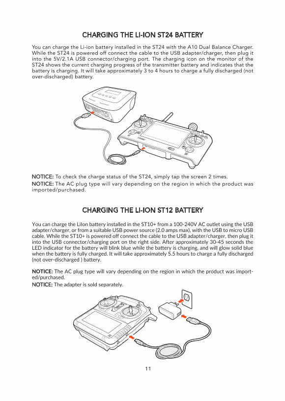
You can charge the Li-ion battery installed in the ST24 with the A10 Dual Balance Charger. While the ST24 is powered off connect the cable to the USB adapter/charger, then plug it into the 5V/2.1A USB connector/charging port. The charging icon on the monitor of the ST24 shows the current charging progress of the transmitter battery and indicates that the battery is charging. It will take approximately 3 to 4 hours to charge a fully discharged (not over-discharged) battery.
CHARGING THE LI-ION ST12 BATTERY
You can charge the LiIon battery installed in the ST10+ from a 100-240V AC outlet using the USB adapter/charger, or from a suitable USB power source (2.0 amps max), with the USB to micro USB cable. While the ST10+ is powered off connect the cable to the USB adapter/charger, then plug it into the USB connector/charging port on the right side. After approximately 30-45 seconds the LED indicator for the battery will blink blue while the battery is charging, and will glow solid blue when the battery is fully charged. It will take approximately 5.5 hours to charge a fully discharged (not over-discharged ) battery.
NOTICE: The AC plug type will vary depending on the region in which the product was import-ed/purchased.NOTICE: The adapter is sold separately.
NOTICE: To check the charge status of the ST24, simply tap the screen 2 times.NOTICE: The AC plug type will vary depending on the region in which the product was imported/purchased.
11
CHARGING THE LIPO FLIGHT BATTERY
Connecting to the power source : the A10 Dual Balance Charger comes with built in switching power supply. You can connect the AC power cord directly to the main AC
socket (110 to 240V AC).
NOTICE: While the A10 is connected to a suitable 110 to 240V AC power source, the combined power output for Channel A and Channel B is 200W, capable of charging two 6-Cell (6S), 4,000mAh LiPo battery packs at 4.3A.
CONNECTING THE BATTERY
CHARGINGBATT/PROGRAM Select: Press INC and DEC to go through all the programs and press START/ENTER to enter LiPo BATT Program (for flight BATT) or Li-ion BATT Program(for proaction™).Mode Select: Press INC and DEC to go through all the modes and press START/ENTER to enter LiPo Balance Charge Mode (for aircraft’s flight battery), to enter Li-ion Balance Charge Mode (for ProAction ground handle).Battery Setting: Press START/ENTER, the current value will start to blink, press INC and DEC to change the value and press START/ENTER to confirm your setting. For the TORNADO H920 battery, it is recommended to set 4A (no more than 8A). For ProAction™ battery, it is recommended to set 2A (no more than 3A).At the same time, the battery cells number will start blinking, press INC and DEC to change the value and press START/ENTER to confirm your setting.For the TORNADO H920 battery, 6S should be selected. For ProAction™, 4S should be selected.Program Start: Press and hold START/ENTER for 3 seconds to start the program.The charger is detecting the battery cell.NOTICE: R shows the number of cells detected by the charger and S is the number of cells set by you at the previous screen. If both numbers are not identical, press STOP to go back to previous screen to recheck the number of cells of the battery pack before going ahead. If both numbers are identical, press START/ENTER to start charging process.If the number of cells do not match after double checking the connection, please contact technical support.
ASSEMBLING THE H920
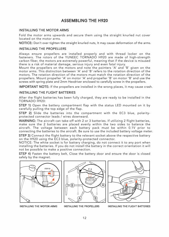
INSTALLING THE MOTOR ARMSFold the motor arms upwards and secure them using the straight knurled nut cover located on the motor arms.NOTICE: Don’t over tighten the straight knurled nuts, It may cause deformation of the arms.
INSTALLING THE PROPELLERSAlways ensure propellers are installed properly and with thread locker on the fasteners. The rotors of the YUNEEC TORNADO H920 are made of high-strength carbon fiber, the motors are extremely powerful, meaning that if the device is misused there is a risk of material damage, serious injury and even fatal injury.Mount the propellers on the motors and note the pointers ‘A’ and ‘B’ given on the motor arms. This distinction between ‘A’ and ‘B’ refers to the rotation direction of the motors. The rotation direction of the motors must match the rotation direction of the propellers. Mount propeller ‘A’ on motor ‘A’ and propeller ‘B’ on motor ‘B’ and use the screws with spring plate and 2mm Hexdriver enclosed to carefully screw in the propellers.IMPORTANT NOTE: If the propellers are installed in the wrong places, it may cause crash.
INSTALLING THE FLIGHT BATTERIESAfter the flight batteries has been fully charged, they are ready to be installed in the TORNADO H920:STEP 1) Open the battery compartment flap with the status LED mounted on it by carefully pulling the top edge of the flap.STEP 2) Slide the batteries into the compartment with the EC3 blue, polarity- protected connector leads / wires downward.WARNING: The aircraft can take-off with 2 or 3 batteries. If utilizing 2 flight batteries, make sure the 2 batteries are placed evenly within the two sides to balance the aircraft. The voltage between each battery pack must be within 0.1V prior to connecting the batteries to the aircraft. Be sure to use the included battery voltage meter.STEP 3) Connect the flight battery to the relevant socket above the respective battery on the H920 using the EC3 blue, polarity-protected connector.NOTICE: The white socket is for battery charging, do not connect it to any port when installing the batteries. If you do not install the battery in the correct orientation it will not be possible to make a positive connection.STEP 4) Fasten the battery belt, Close the battery door and ensure the door is closed safely by the magnet.
INSTALLING THE MOTOR ARMS INSTALLING THE PROPELLERS INSTALLING THE FLIGHT BATTERIES
12
FLIGHT CONTROLS
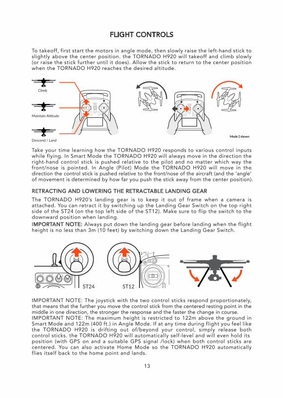
To takeoff, first start the motors in angle mode, then slowly raise the left-hand stick to slightly above the center position. the TORNADO H920 will takeoff and climb slowly (or raise the stick further until it does). Allow the stick to return to the center position when the TORNADO H920 reaches the desired altitude.
Take your time learning how the TORNADO H920 responds to various control inputs while flying. In Smart Mode the TORNADO H920 will always move in the direction the right-hand control stick is pushed relative to the pilot and no matter which way the front/nose is pointed. In Angle (Pilot) Mode the TORNADO H920 will move in the direction the control stick is pushed relative to the front/nose of the aircraft (and the ‘angle’ of movement is determined by how far you push the stick away from the center position).
RETRACTING AND LOWERING THE RETRACTABLE LANDING GEARThe TORNADO H920’s landing gear is to keep it out of frame when a camera is attached. You can retract it by switching up the Landing Gear Switch on the top right side of the ST24 (on the top left side of the ST12). Make sure to flip the switch to the downward position when landing.IMPORTANT NOTE: Always put down the landing gear before landing when the flight height is no less than 3m (10 feet) by switching down the Landing Gear Switch.
IMPORTANT NOTE: The joystick with the two control sticks respond proportionately, that means that the further you move the control stick from the centered resting point in the middle in one direction, the stronger the response and the faster the change in course.IMPORTANT NOTE: The maximum height is restricted to 122m above the ground in Smart Mode and 122m (400 ft.) in Angle Mode. If at any time during flight you feel like the TORNADO H920 is drifting out of/beyond your control, simply release both control sticks. the TORNADO H920 will automatically self-level and will even hold itsposition (with GPS on and a suitable GPS signal /lock) when both control sticks are centered. You can also activate Home Mode so the TORNADO H920 automatically flies itself back to the home point and lands.
13
ST24 ST12
LANDING — Position the TORNADO H920 above the area where you would like to land. Slowly lower the left-hand stick to below the center position. The TORNADO H920 will descend slowly and land. After the TORNADO H920 lands, press and hold the START/STOP button for approximately 2 seconds to stop the motors. Activate Home Mode and the TORNADO H920 will automatically fly itself back to the home point and will land within a 26 feet (8 meter) diameter circle around it.WARNING: Always land as soon as possible after the first level low voltage battery warning, or land immediately after the second level low voltage battery warning. And if at any time the Aircraft Battery Voltage shown on the screen is below 21.7V, land the TORNADO H920 immediately.AFTER LANDING — ALWAYS turn off the TORNADO H920 BEFORE turning off the ST24/ST12. Then remove the battery from the TORNADO H920 and allow it to cool to ambient/room temperature before recharging.
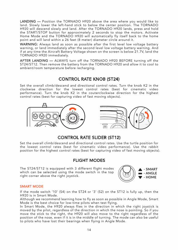
CONTROL RATE KNOB (ST24)Set the overall climb/descend and directional control rates. Turn the knob K2 in the clockwise direction for the lowest control rates (best for cinematic video performance). Turn the knob K2 in the couterclockwise direction for the highest control rates (best for capturing video of fast moving objects).
CONTROL RATE SLIDER (ST12)Set the overall climb/descend and directional control rates. Use the turtle position for the lowest control rates (best for cinematic video performance). Use the rabbit position for the highest control rates (best for capturing video of fast moving objects).
FLIGHT MODES
The ST24/ST12 is equipped with 3 different flight modes which can be selected using the mode switch in the top right corner above the right joystick.
SMART MODEIf the mode switch ‘10’ (S4) on the ST24 or ‘3’ (S2) on the ST12 is fully up, then the H920 is in Smart Mode.Although we recommend learning how to fly as soon as possible in Angle Mode, Smart Mode is the best choice for low-time pilots when test flying.In Smart Mode, the H920 always flies in the direction in which the right joystick is moved by the pilot, regardless of the direction in which the nose is pointing. So if you move the stick to the right, the H920 will also move to the right regardless of the position of the nose, even if it is in the middle of turning. The mode can also be useful to pilots who have lost their bearings when flying in Angle Mode.
14
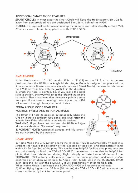
ADDITIONAL SMART MODE FEATURES:SMART CIRCLE : In most cases the Smart Circle will keep the H920 approx. 8m / 26 ft. away from you provided you are positioned 8 m /26 ft. behind the H920.NOTICE: For optimal performance, aiming the Remote controller directly at the H920.
HOME MODEIn Home Mode the GPS system allows the Tornado H920 to automatically fly back in a straight line toward the direction of the last take-off position, and automatically land within 13-26 ft (4-8m) of the pilot. This can be very helpful for first-time pilots who are not quite ready to land the TORNADO H920 themselves. It can also be helpful for pilots that lose orientation during flight; simply activate Home Mode until the TORNADO H920 automatically moves toward the home position, and once you’ve confirmed orientation switch back to Angle (Pilot) Mode. And if the TORNADO H920 ever loses the link with the ST24/ST12 it will automatically enter Home Mode.When Home Mode is activated the TORNADO H920 will respond as follows:A) When flying higher than 33 feet (10 meters) the TORNADO H920 will maintain the current altitude, fly back to the home point.
ANGLE MODEIf the Mode switch ‘10’ (S4) on the ST24 or ‘3’ (S2) on the ST12 is in the centre position, then the H920 is in Angle Mode. Angle Mode is designed for pilots with a little experience (those who have already mastered Smart Mode), because in this mode the H920 moves in line with the joystick, in the direction in which the nose is pointed. So, if you move the right stick to the left, the H920 will tilt to the left and thus move to the left. That is assuming that the nose is pointing away from you. If the nose is pointing towards you, the H920 will move to the right from your point of view.EXTRA ANGLE MODE FEATURES:POSITION FREELY AND RETAIN ALTITUDEThe H920 will hold its position automatically when the GPS on (if there is sufficient GPS signal) and it will retain the altitude level if the left stick is in the middle position.WARNING: If you have not mastered the H920 in Angle Mode, accidents or “fly aways” may result.IMPORTANT NOTE: Accidental damage and “fly aways” are not covered by the warranty.
15
*The stick controls can be applied to both ST12 & ST24.
16
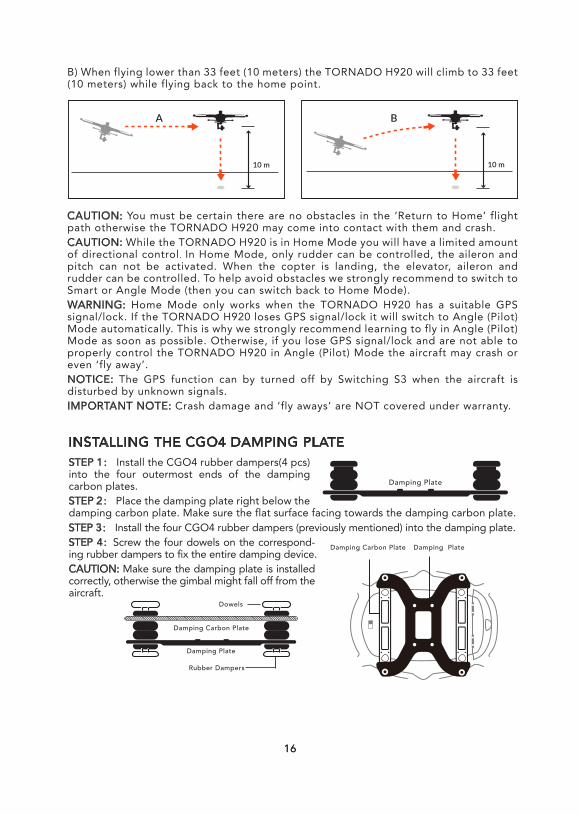
B) When flying lower than 33 feet (10 meters) the TORNADO H920 will climb to 33 feet (10 meters) while flying back to the home point.
CAUTION: You must be certain there are no obstacles in the ‘Return to Home’ flight path otherwise the TORNADO H920 may come into contact with them and crash.CAUTION: While the TORNADO H920 is in Home Mode you will have a limited amount of directional control. In Home Mode, only rudder can be controlled, the aileron and pitch can not be activated. When the copter is landing, the elevator, aileron and rudder can be controlled. To help avoid obstacles we strongly recommend to switch to Smart or Angle Mode (then you can switch back to Home Mode).WARNING: Home Mode only works when the TORNADO H920 has a suitable GPS signal/lock. If the TORNADO H920 loses GPS signal/lock it will switch to Angle (Pilot) Mode automatically. This is why we strongly recommend learning to fly in Angle (Pilot) Mode as soon as possible. Otherwise, if you lose GPS signal/lock and are not able to properly control the TORNADO H920 in Angle (Pilot) Mode the aircraft may crash or even ‘fly away’.NOTICE: The GPS function can by turned off by Switching S3 when the aircraft is disturbed by unknown signals. IMPORTANT NOTE: Crash damage and ‘fly aways’ are NOT covered under warranty.
16
STEP 1: Install the CGO4 rubber dampers(4 pcs) into the four outermost ends of the damping carbon plates.STEP 2: Place the damping plate right below the damping carbon plate. Make sure the flat surface facing towards the damping carbon plate.
Damping Plate
Damping Carbon Plate Damping Plate
Damping Carbon Plate
Damping Plate
Dowels
Rubber Dampers
STEP 3: Install the four CGO4 rubber dampers (previously mentioned) into the damping plate.STEP 4:Screw the four dowels on the correspond-ing rubber dampers to fix the entire damping device.CAUTION: Make sure the damping plate is installed correctly, otherwise the gimbal might fall off from the aircraft.
INSTALLING THE CGO4 DAMPING PLATE
1717
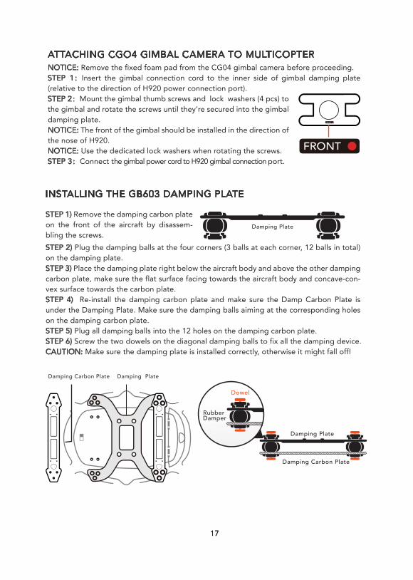
ATTACHING CGO4 GIMBAL CAMERA TO MULTICOPTERNOTICE: Remove the fixed foam pad from the CG04 gimbal camera before proceeding.STEP 1:Insert the gimbal connection cord to the inner side of gimbal damping plate (relative to the direction of H920 power connection port).STEP 2:Mount the gimbal thumb screws and lock washers (4 pcs) to the gimbal and rotate the screws until they’re secured into the gimbal damping plate.NOTICE: The front of the gimbal should be installed in the direction of the nose of H920.NOTICE: Use the dedicated lock washers when rotating the screws.STEP 3:Connect the gimbal power cord to H920 gimbal connection port.
INSTALLING THE GB603 DAMPING PLATE
STEP 1) Remove the damping carbon plate on the front of the aircraft by disassem-bling the screws.STEP 2) Plug the damping balls at the four corners (3 balls at each corner, 12 balls in total) on the damping plate.STEP 3) Place the damping plate right below the aircraft body and above the other damping carbon plate, make sure the flat surface facing towards the aircraft body and concave-con-vex surface towards the carbon plate.STEP 4) Re-install the damping carbon plate and make sure the Damp Carbon Plate is under the Damping Plate. Make sure the damping balls aiming at the corresponding holes on the damping carbon plate.STEP 5) Plug all damping balls into the 12 holes on the damping carbon plate.STEP 6) Screw the two dowels on the diagonal damping balls to fix all the damping device.CAUTION: Make sure the damping plate is installed correctly, otherwise it might fall off!
Damping Plate
Damping Carbon Plate
Damping Plate
Dowel
Rubber Damper
Damping Carbon Plate
Damping Plate
INSTALLING THE GB603 GIMBAL AND CAMERA
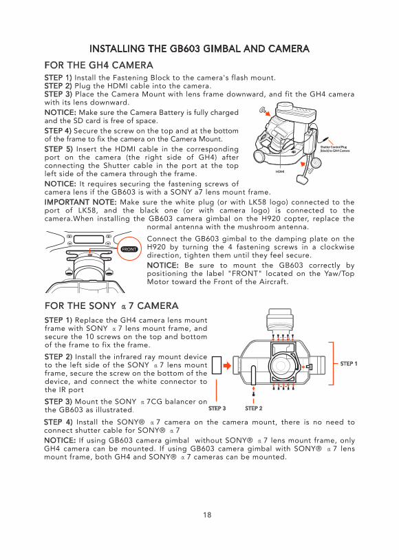
FOR THE GH4 CAMERASTEP 1) Install the Fastening Block to the camera's flash mount.STEP 2) Plug the HDMI cable into the camera.STEP 3) Place the Camera Mount with lens frame downward, and fit the GH4 camera with its lens downward.NOTICE: Make sure the Camera Battery is fully charged and the SD card is free of space.STEP 4) Secure the screw on the top and at the bottom of the frame to fix the camera on the Camera Mount.STEP 5) Insert the HDMI cable in the corresponding port on the camera (the right side of GH4) after connecting the Shutter cable in the port at the top left side of the camera through the frame.NOTICE: It requires securing the fastening screws of camera lens if the GB603 is with a SONY a7 lens mount frame.IMPORTANT NOTE: Make sure the white plug (or with LK58 logo) connected to the port of LK58, and the black one (or with camera logo) is connected to the camera.When installing the GB603 camera gimbal on the H920 copter, replace the
normal antenna with the mushroom antenna.Connect the GB603 gimbal to the damping plate on the H920 by turning the 4 fastening screws in a clockwise direction, tighten them until they feel secure.NOTICE: Be sure to mount the GB603 correctly by positioning the label "FRONT" located on the Yaw/Top Motor toward the Front of the Aircraft.
18
FOR THE SONY α7 CAMERASTEP 1) Replace the GH4 camera lens mount frame with SONY α7 lens mount frame, and secure the 10 screws on the top and bottom of the frame to fix the frame. STEP 2) Install the infrared ray mount device to the left side of the SONY α7 lens mount frame, secure the screw on the bottom of the device, and connect the white connector to the IR port STEP 3) Mount the SONY α7CG balancer on the GB603 as illustrated.
STEP 1
STEP 2STEP 3
STEP 4) Install the SONY® α7 camera on the camera mount, there is no need to connect shutter cable for SONY® α7NOTICE: If using GB603 camera gimbal without SONY® α7 lens mount frame, only GH4 camera can be mounted. If using GB603 camera gimbal with SONY® α7 lens mount frame, both GH4 and SONY® α7 cameras can be mounted.
19
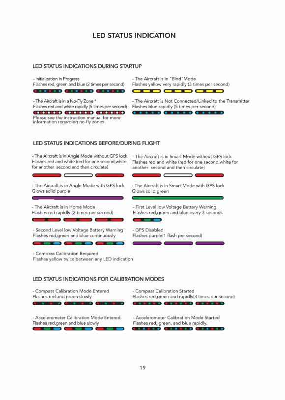
LED STATUS INDICATIONS DURING STARTUP
- Initialization in Progress Flashes red, green and blue (2 times per second)
- The Aircraft is in "Bind"Mode Flashes yellow very rapidly (3 times per second)
- The Aircraft is Not Connected/Linked to the Transmitter Flashes blue rapidly (5 times per second)
- The Aircraft is in a No-Fly Zone *Flashes red and white rapidly (5 times per second)
Please see the instruction manual for moreinformation regarding no-fly zones
LED STATUS INDICATIONS BEFORE/DURING FLIGHT
- The Aircraft is in Smart Mode without GPS lockFlashes red and white (red for one second,white for another second and then circulate)
- The Aircraft is in Angle Mode with GPS lockGlows solid purple
- The Aircraft is in Angle Mode without GPS lockFlashes red and white (red for one second,whitefor another second and then circulate)
- The Aircraft is in Home ModeFlashes red rapidly (2 times per second)
- First Level low Voltage Battery WarningFlashes red,green and blue every 3 seconds
- Second Level low Voltage Battery WarningFlashes red,green and blue continuously
- GPS DisabledFlashes purple(1 flash per second)
- Compass Calibration RequiredFlashes yellow twice between any LED indication
LED STATUS INDICATIONS FOR CALIBRATION MODES
- Compass Calibration Mode EnteredFlashes red and green slowly
- Compass Calibration Started Flashes red,green and rapidly(3 times per second)
- Accelerometer Calibration Mode EnteredFlashes red,green and blue slowly
- Accelerometer Calibration Mode StartedFlashes red, green, and blue rapidly.
LED STATUS INDICATION
- The Aircraft is in Smart Mode with GPS lock Glows solid green

PREPARING TO FLY
WARNING: Always operate the TORNADO H920 in open areas (approximately 10000 square feet/930 square meters or more) that are free from people, vehicles, trees and other obstructions. Never fly near or above crowds, airports or buildings.Never attempt to operate TORNADO H920 nearby tall buildings/obstructions that do not offer a clear view of the sky (a minimum clearance of 100°).Be sure to place the TORNADO H920 on a level and stable surface before powering ON the Tornado H920 Aircraft and the ST24/ST12 Ground Station.
FLYINGPOWERING ON/OFFNOTICE: ALWAYS turn on the ST24/ST12 and allow it to boot up BEFORE turning on the TORNADO H920 (and ALWAYS turn off the TORNADO H920 BEFORE turning off the ST24/ST12).If the main LED status indicator flashes yellow, you will need to follow the compass calibration procedure. If the main LED status indicator is flashing blue, double check that the ST24/ST12 is powered on and set to the correct model memory. If the main LED status indicator is still flashing blue, please bind the aircraft to the ST24/ST12.
STARTING/STOPPING THE MOTORSStep back approximately 26 feet (8 meters) behind the TORNADO H920. Press and hold the START/STOP button for about 3 seconds to start, and about 2 seconds to stop the motors.NOTICE: If the motors can't be started in such cases of compass error, insufficient GPS signal with GPS on, or in home mode, start the motors in angle mode.IMPORTANT NOTE: In the rabbit mode, the motor can also be activated by lowering the left-hand stick to the lowest position, and then push the rudder stick to the right and left side for several times. DO NOT PUSH the stick randomly, in case of activating the motor accidentally.
Step back approximately 26 ft (8 m) behind the TORNADO H920
20
COMPASS CALIBRATION
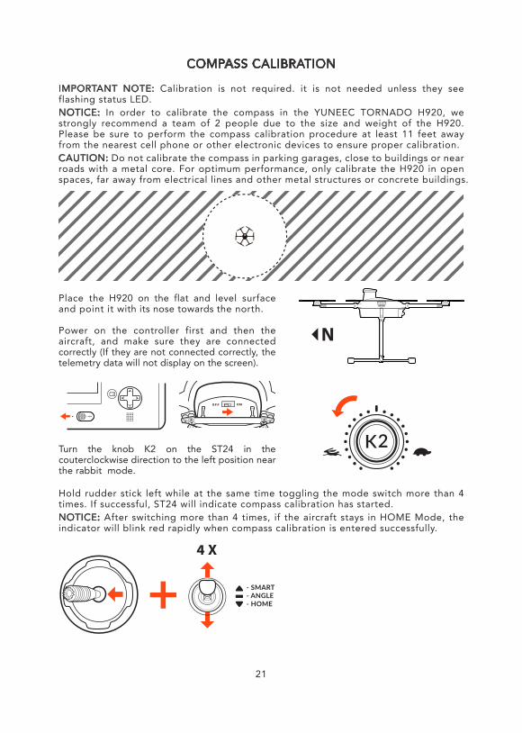
IMPORTANT NOTE: Calibration is not required. it is not needed unless they see flashing status LED.NOTICE: In order to calibrate the compass in the YUNEEC TORNADO H920, we strongly recommend a team of 2 people due to the size and weight of the H920. Please be sure to perform the compass calibration procedure at least 11 feet away from the nearest cell phone or other electronic devices to ensure proper calibration.CAUTION: Do not calibrate the compass in parking garages, close to buildings or near roads with a metal core. For optimum performance, only calibrate the H920 in open spaces, far away from electrical lines and other metal structures or concrete buildings.
Place the H920 on the flat and level surface and point it with its nose towards the north.
Power on the controller first and then the aircraft, and make sure they are connected correctly (If they are not connected correctly, the telemetry data will not display on the screen).
Turn the knob K2 on the ST24 in the couterclockwise direction to the left position near the rabbit mode.
Hold rudder stick left while at the same time toggling the mode switch more than 4 times. If successful, ST24 will indicate compass calibration has started.NOTICE: After switching more than 4 times, if the aircraft stays in HOME Mode, the indicator will blink red rapidly when compass calibration is entered successfully.
21
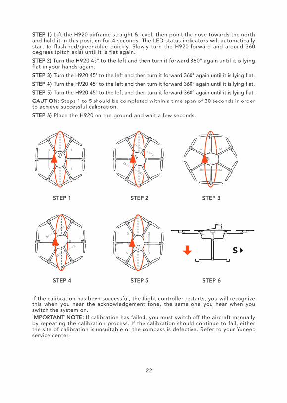
STEP 1) Lift the H920 airframe straight & level, then point the nose towards the north and hold it in this position for 4 seconds. The LED status indicators will automatically start to flash red/green/blue quickly. Slowly turn the H920 forward and around 360 degrees (pitch axis) until it is flat again.STEP 2) Turn the H920 45° to the left and then turn it forward 360° again until it is lying flat in your hands again.STEP 3) Turn the H920 45° to the left and then turn it forward 360° again until it is lying flat.STEP 4) Turn the H920 45° to the left and then turn it forward 360° again until it is lying flat.STEP 5) Turn the H920 45° to the left and then turn it forward 360° again until it is lying flat.CAUTION: Steps 1 to 5 should be completed within a time span of 30 seconds in order to achieve successful calibration.STEP 6) Place the H920 on the ground and wait a few seconds.
If the calibration has been successful, the flight controller restarts, you will recognize this when you hear the acknowledgement tone, the same one you hear when you switch the system on.IMPORTANT NOTE: If calibration has failed, you must switch off the aircraft manually by repeating the calibration process. If the calibration should continue to fail, either the site of calibration is unsuitable or the compass is defective. Refer to your Yuneec service center.
STEP 1 STEP 2 STEP 3
STEP 4 STEP 5 STEP 6
22
23
BINDING (SINGLE MODE)
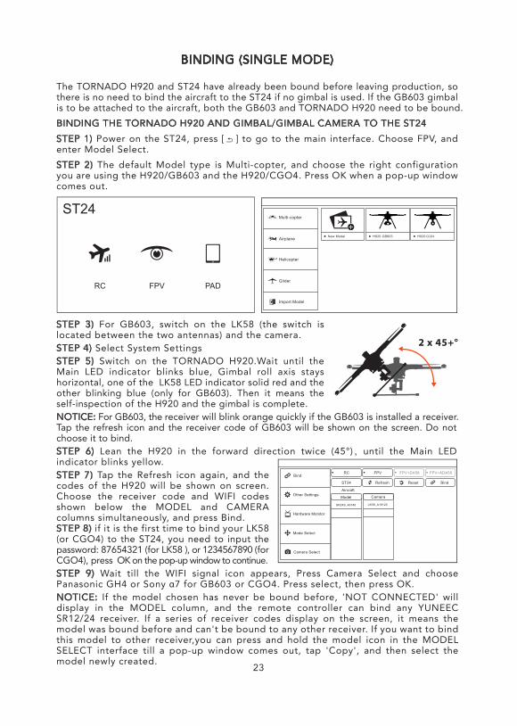
The TORNADO H920 and ST24 have already been bound before leaving production, so there is no need to bind the aircraft to the ST24 if no gimbal is used. If the GB603 gimbal is to be attached to the aircraft, both the GB603 and TORNADO H920 need to be bound.BINDING THE TORNADO H920 AND GIMBAL/GIMBAL CAMERA TO THE ST24STEP 1) Power on the ST24, press [ ] to go to the main interface. Choose FPV, and enter Model Select.STEP 2) The default Model type is Multi-copter, and choose the right configuration you are using the H920/GB603 and the H920/CGO4. Press OK when a pop-up window comes out.
STEP 3) For GB603, switch on the LK58 (the switch is located between the two antennas) and the camera.STEP 4) Select System SettingsSTEP 5) Switch on the TORNADO H920.Wait until the Main LED indicator blinks blue, Gimbal roll axis stays horizontal, one of the LK58 LED indicator solid red and the other blinking blue (only for GB603). Then it means the self-inspection of the H920 and the gimbal is complete.NOTICE: For GB603, the receiver will blink orange quickly if the GB603 is installed a receiver.Tap the refresh icon and the receiver code of GB603 will be shown on the screen. Do not choose it to bind.STEP 6) Lean the H920 in the forward direction twice (45°),until the Main LED indicator blinks yellow.STEP 7) Tap the Refresh icon again, and the codes of the H920 will be shown on screen. Choose the receiver code and WIFI codes shown below the MODEL and CAMERA columns simultaneously, and press Bind.STEP 8) if it is the first time to bind your LK58 (or CGO4) to the ST24, you need to input the password: 87654321 (for LK58 ), or 1234567890 (for CGO4), press OK on the pop-up window to continue.STEP 9) Wait till the WIFI signal icon appears, Press Camera Select and choose Panasonic GH4 or Sony α7 for GB603 or CGO4. Press select, then press OK.NOTICE: If the model chosen has never be bound before, 'NOT CONNECTED' will display in the MODEL column, and the remote controller can bind any YUNEEC SR12/24 receiver. If a series of receiver codes display on the screen, it means the model was bound before and can't be bound to any other receiver. If you want to bind this model to other receiver,you can press and hold the model icon in the MODEL SELECT interface till a pop-up window comes out, tap 'Copy', and then select the model newly created.
CGO4
PADFPVRC
ST24
CAMERA CONTROLS (SINGLE MODE)
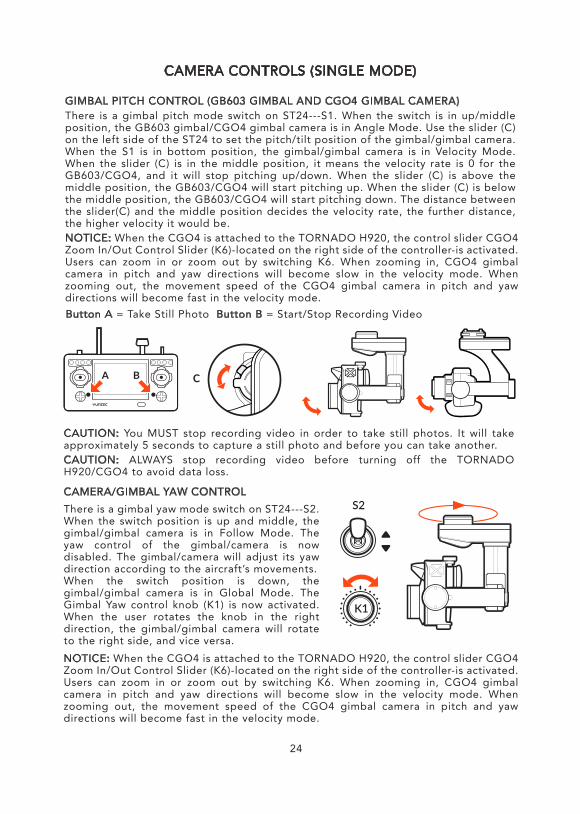
GIMBAL PITCH CONTROL (GB603 GIMBAL AND CGO4 GIMBAL CAMERA)There is a gimbal pitch mode switch on ST24---S1. When the switch is in up/middle position, the GB603 gimbal/CGO4 gimbal camera is in Angle Mode. Use the slider (C) on the left side of the ST24 to set the pitch/tilt position of the gimbal/gimbal camera. When the S1 is in bottom position, the gimbal/gimbal camera is in Velocity Mode. When the slider (C) is in the middle position, it means the velocity rate is 0 for the GB603/CGO4, and it will stop pitching up/down. When the slider (C) is above the middle position, the GB603/CGO4 will start pitching up. When the slider (C) is below the middle position, the GB603/CGO4 will start pitching down. The distance between the slider(C) and the middle position decides the velocity rate, the further distance, the higher velocity it would be.NOTICE: When the CGO4 is attached to the TORNADO H920, the control slider CGO4 Zoom In/Out Control Slider (K6)-located on the right side of the controller-is activated. Users can zoom in or zoom out by switching K6. When zooming in, CGO4 gimbal camera in pitch and yaw directions will become slow in the velocity mode. When zooming out, the movement speed of the CGO4 gimbal camera in pitch and yaw directions will become fast in the velocity mode.
CAUTION: You MUST stop recording video in order to take still photos. It will take approximately 5 seconds to capture a still photo and before you can take another.CAUTION: ALWAYS stop recording video before turning off the TORNADO H920/CGO4 to avoid data loss.
CAMERA/GIMBAL YAW CONTROLThere is a gimbal yaw mode switch on ST24---S2. When the switch position is up and middle, the gimbal/gimbal camera is in Follow Mode. The yaw control of the gimbal/camera is now disabled. The gimbal/camera will adjust its yaw direction according to the aircraft’s movements.When the switch position is down, the gimbal/gimbal camera is in Global Mode. The Gimbal Yaw control knob (K1) is now activated. When the user rotates the knob in the right direction, the gimbal/gimbal camera will rotate to the right side, and vice versa.
Button A = Take Still Photo Button B = Start/Stop Recording Video
24
NOTICE: When the CGO4 is attached to the TORNADO H920, the control slider CGO4 Zoom In/Out Control Slider (K6)-located on the right side of the controller-is activated. Users can zoom in or zoom out by switching K6. When zooming in, CGO4 gimbal camera in pitch and yaw directions will become slow in the velocity mode. When zooming out, the movement speed of the CGO4 gimbal camera in pitch and yaw directions will become fast in the velocity mode.
25
CAUTION: We recommend that the CGO4 gimbal camera should be operated according to the above steps strictly, otherwise it may cause unexpected results of lens failing to retract or video loss etc. NOTICE: When using GB603, press the stop recording button to save the images first, then power off the H920, and turn off the camera at lastWhen using CGO4, stop recording first, then switch off the camera by ST-24, and switch off the H920 at last.
BINDING H920 MULTICOPTER TO THE ST12 (TEAM MODE)
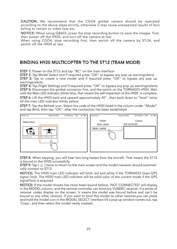
STEP 1: Power on the ST12 and tap “RC” on the main interfaceSTEP 2: Tap Model Select and if required press “OK” to bypass any pop up warning/alerts. STEP 3: Tap to create a new model and if required press “OK” to bypass any pop up warnings/alerts.STEP 4: Tap Flight Settings and if required press “OK” to bypass any pop up warnings/alerts.STEP 5: Disconnect the gimbal connector first, and the switch on the TORNADO H920, Wait until the Main LED indicator blinks blue, that means the self-inspection of the H920 is complete. STEP 6: Lift the H920 back end upward approximately 45° , then back down to “level” twice till the main LED indicator blinks yellow.STEP 7: Tap the Refresh icon. Select the code of the H920 listed in the column under ”Model” and tap Bind, then tap “OK” after the connection has been established
STEP 8: When tapping, you will hear two long beeps from the aircraft. That means the ST12 is bound to the H920 successfully.STEP 9: Tap [ ] twice to return to the main screen and the model /receiver should automati-cally connect to ST12NOTICE: The H920 main LED indicator will blink red and white if the TORNADO loses GPS signal /lock. The H920 main LED indicator will be solid color of the current mode if the GPS signal/lock is acquired.NOTICE: If the model chosen has never been bound before, 'NOT CONNECTED' will display in the MODEL column, and the remote controller can bind any YUNEEC receiver. If a series of receiver codes display on the screen, it means the model was bound before and can't be bound to any other receiver. If you want to bind this model to other receiver,you can press and hold the model icon in the MODEL SELECT interface till a pop-up window comes out, tap 'Copy', and then select the model newly created.
Model: 4K Welcome,Pilot 10:48:28 pm 10
SR24_16042
SR24_16042 Not connectedModel Camera
Model: 4K Welcome,Pilot 10:48:28 pm 10
Model Select
New Model TORNADO H920
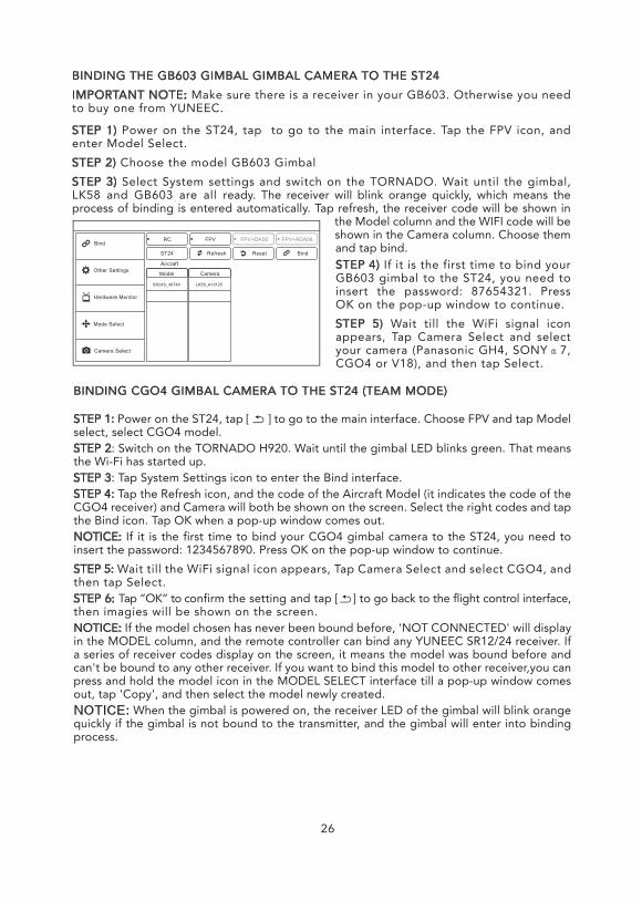
STEP 4) If it is the first time to bind your GB603 gimbal to the ST24, you need to insert the password: 87654321. Press OK on the pop-up window to continue.STEP 5) Wait till the WiFi signal icon appears, Tap Camera Select and select your camera (Panasonic GH4, SONYα7, CGO4 or V18), and then tap Select.
BINDING THE GB603 GIMBAL GIMBAL CAMERA TO THE ST24IMPORTANT NOTE: Make sure there is a receiver in your GB603. Otherwise you need to buy one from YUNEEC.
STEP 1) Power on the ST24, tap to go to the main interface. Tap the FPV icon, and enter Model Select.STEP 2) Choose the model GB603 GimbalSTEP 3) Select System settings and switch on the TORNADO. Wait until the gimbal, LK58 and GB603 are all ready. The receiver will blink orange quickly, which means the process of binding is entered automatically. Tap refresh, the receiver code will be shown in
the Model column and the WIFI code will be shown in the Camera column. Choose them and tap bind.
26
BINDING CGO4 GIMBAL CAMERA TO THE ST24 (TEAM MODE)
STEP 1: Power on the ST24, tap [ ] to go to the main interface. Choose FPV and tap Model select, select CGO4 model.STEP 2: Switch on the TORNADO H920. Wait until the gimbal LED blinks green. That means the Wi-Fi has started up.STEP 3: Tap System Settings icon to enter the Bind interface.STEP 4: Tap the Refresh icon, and the code of the Aircraft Model (it indicates the code of the CGO4 receiver) and Camera will both be shown on the screen. Select the right codes and tap the Bind icon. Tap OK when a pop-up window comes out.NOTICE: If it is the first time to bind your CGO4 gimbal camera to the ST24, you need to insert the password: 1234567890. Press OK on the pop-up window to continue.STEP 5: Wait till the WiFi signal icon appears, Tap Camera Select and select CGO4, and then tap Select.STEP 6: Tap “OK” to confirm the setting and tap [ ] to go back to the flight control interface, then imagies will be shown on the screen.NOTICE: If the model chosen has never been bound before, 'NOT CONNECTED' will display in the MODEL column, and the remote controller can bind any YUNEEC SR12/24 receiver. If a series of receiver codes display on the screen, it means the model was bound before and can't be bound to any other receiver. If you want to bind this model to other receiver,you can press and hold the model icon in the MODEL SELECT interface till a pop-up window comes out, tap 'Copy', and then select the model newly created.NOTICE: When the gimbal is powered on, the receiver LED of the gimbal will blink orange quickly if the gimbal is not bound to the transmitter, and the gimbal will enter into binding process.
27
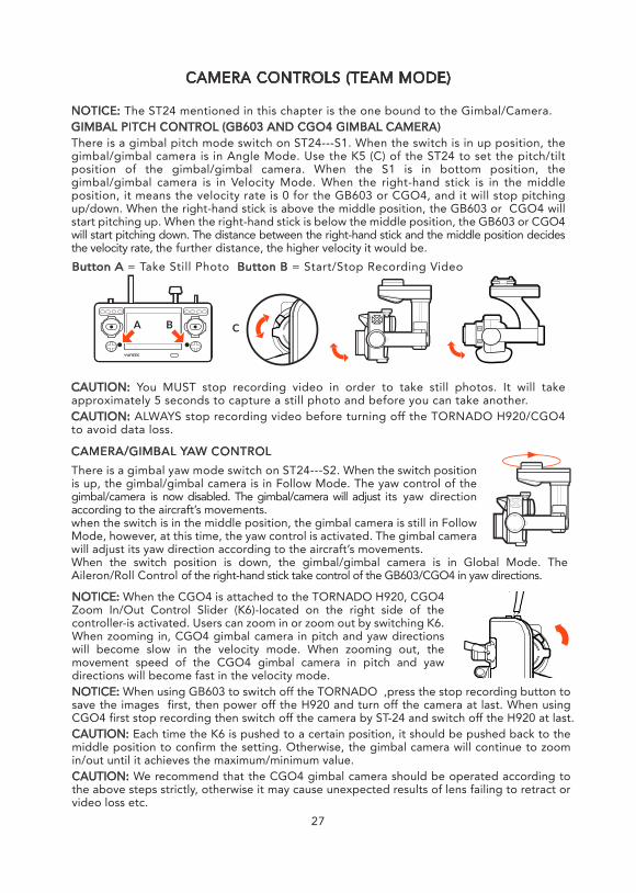
CAMERA CONTROLS (TEAM MODE)
NOTICE: The ST24 mentioned in this chapter is the one bound to the Gimbal/Camera.GIMBAL PITCH CONTROL (GB603 AND CGO4 GIMBAL CAMERA)There is a gimbal pitch mode switch on ST24---S1. When the switch is in up position, the gimbal/gimbal camera is in Angle Mode. Use the K5 (C) of the ST24 to set the pitch/tilt position of the gimbal/gimbal camera. When the S1 is in bottom position, the gimbal/gimbal camera is in Velocity Mode. When the right-hand stick is in the middle position, it means the velocity rate is 0 for the GB603 or CGO4, and it will stop pitching up/down. When the right-hand stick is above the middle position, the GB603 or CGO4 will start pitching up. When the right-hand stick is below the middle position, the GB603 or CGO4 will start pitching down. The distance between the right-hand stick and the middle position decides the velocity rate, the further distance, the higher velocity it would be.
CAUTION: You MUST stop recording video in order to take still photos. It will take approximately 5 seconds to capture a still photo and before you can take another.CAUTION: ALWAYS stop recording video before turning off the TORNADO H920/CGO4 to avoid data loss.
CAMERA/GIMBAL YAW CONTROLThere is a gimbal yaw mode switch on ST24---S2. When the switch position is up, the gimbal/gimbal camera is in Follow Mode. The yaw control of the gimbal/camera is now disabled. The gimbal/camera will adjust its yaw direction according to the aircraft’s movements.when the switch is in the middle position, the gimbal camera is still in Follow Mode, however, at this time, the yaw control is activated. The gimbal camera will adjust its yaw direction according to the aircraft’s movements.When the switch position is down, the gimbal/gimbal camera is in Global Mode. The Aileron/Roll Control of the right-hand stick take control of the GB603/CGO4 in yaw directions.
Button A = Take Still Photo Button B = Start/Stop Recording Video
NOTICE: When the CGO4 is attached to the TORNADO H920, CGO4 Zoom In/Out Control Slider (K6)-located on the right side of the controller-is activated. Users can zoom in or zoom out by switching K6. When zooming in, CGO4 gimbal camera in pitch and yaw directions will become slow in the velocity mode. When zooming out, the movement speed of the CGO4 gimbal camera in pitch and yaw directions will become fast in the velocity mode.NOTICE: When using GB603 to switch off the TORNADO ,press the stop recording button to save the images first, then power off the H920 and turn off the camera at last. When using CGO4 first stop recording then switch off the camera by ST-24 and switch off the H920 at last.CAUTION: Each time the K6 is pushed to a certain position, it should be pushed back to the middle position to confirm the setting. Otherwise, the gimbal camera will continue to zoom in/out until it achieves the maximum/minimum value.CAUTION: We recommend that the CGO4 gimbal camera should be operated according to the above steps strictly, otherwise it may cause unexpected results of lens failing to retract or video loss etc.
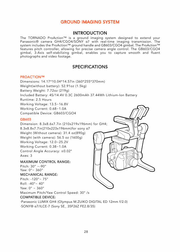
SPECIFICATIONS
PROACTION™Dimensions: 14.17*10.04*14.57in (360*255*370mm)Weight(without battery): 52.91oz (1.5kg)Battery Weight: 7.72oz (219g)Included Battery: 4S/14.4V 0.3C 2600mAh 37.44Wh Lithium-Ion BatteryRuntime: 2.5 HoursWorking Voltage: 13.5~16.8VWorking Current: 0.68~1.0ACompatible Device: GB603/CGO4
GB603Dimension: 8.3x8.6x7.7in (210x219x196mm) for GH4;8.3x8.8x7.7in(210x223x196mm)for sony α7Weight (Without camera): 31.4 oz(890g)Weight (with camera): 56.5 oz (1600g)Working Voltage: 12.0~25.2VWorking Current: 0.38~1.0AControl Angle Accuracy: ±0.02°Axes: 3
MAXIMUM CONTROL RANGE:Pitch: 30° ~-90°Yaw: 0°~ 360°MECHANICAL RANGE:Pitch: -120°~ 75°Roll: -40°~ 40°Yaw: 0° ~ 360°Maximum Pitch/Yaw Control Speed: 30° /sCOMPATIBLE DEVICE: ·Panasonic LUMIX GH4 (Olympus M.ZUIKO DIGITAL ED 12mm f/2.0)·SONY® α7/ILCE-7 (Sony SE_ 35F26Z FE2.8/35)
GROUND IMAGING SYSTEM
INTRODUCTIONThe TORNADO ProAction™ is a ground imaging system designed to extend your Panasonic® camera GH4/CGO4/SONY α7 with real-time imaging transmission. The system includes the ProAction™ ground handle and GB603/CGO4 gimbal. The ProAction™ features pitch controller, allowing for precise camera angle control. The GB603/CGO4 gimbal, 3-Axis self-stabilizing gimbal, enables you to capture smooth and fluent photographs and video footage.
28
LITHIUM BATTERY WARNINGS AND USAGE GUIDELINES
WARNING: Lithium batteries are significantly more volatile than alkaline, NiCd or NiMH batteries. All instructions and warnings must be followed exactly to prevent property damage and/or serious injury as the mishandling of Lithium batteries can result in fire. By handling, charging or using the included Li-ion batteries battery you assume all risks associated with Lithium batteries. If you do not agree with these conditions please return the complete product in new, unused condition to the place of purchase immediately. You must always charge the Lithium battery in a safe, well-ventilated area away from flammable materials.Do not disassemble or modify the battery pack. The battery pack is equipped with built-in safety/protection features. Should these features be disabled, the battery pack can leak, overheat, emit smoke, burst and/or ignite.Do not discard the battery pack into fire or heat it. Otherwise, its insulation can melt down, its gas release vent or safety features will be damaged and/or its electrolyte can ignite, possibly leading to leakage, overheating, smoke emission, bursting and/or ignition on it.Do not immerse the battery pack in water or seawater and do not allow it to get wet. Otherwise, the protective features in it can be damaged, it can be charged with extremely high current and voltage, abnormal chemical reactions may occur in it, possibly leading to leakage, smoke emission, bursting and/or ignition.Do not pierce the battery pack with a nail or other sharp objects, strike it with a hammer, or step on it. Otherwise, the battery pack will become damaged and deformed, internal short-circuiting can occur, possibly leading to acid leakage, overheating, smoke emission, bursting and/or ignition.Do not strike or throw the battery pack. The impact might cause leakage, overheating, smoke emission, bursting and/or ignition. Also, if the protective feature in it becomes damaged, it could become charged with an extremely high current and voltage, abnormal chemical reactions can occur, which can lead to acid leakage, overheating smoke emission, bursting and/or ignition.When charging Battery Pack, please put battery in a fire proof container. Please don't leave battery pack and charger on the wood material or carpet and unattended. Use specific Lithium charger only. Do not use a NiMH or NiCd charger- Failure to do so may a cause fire, which may result in personal injury and property damage.Always monitor charging process to assure batteries are being charged properly. Failure to do so may result in fire. If at any time the user witnesses a battery starting to balloon, swell up, smoke or hot, discontinue charging process immediately, disconnect the battery and observe it in a safe place for approximately 15 minutes. This may cause the battery to leak, and the reaction with air may cause the chemicals to ignite, resulting in fire.Wire lead shorts can cause fire! If the wire is accidentally short, the battery must be placed in a safe area for observation for approximately 15 minutes. Additionally, if a short occurs and contact is made with metal, severe injuries may occur due to the conductibility of electric current.Never store or charge battery pack inside a car in extreme temperatures, since extreme temperature could ignite fire.
29
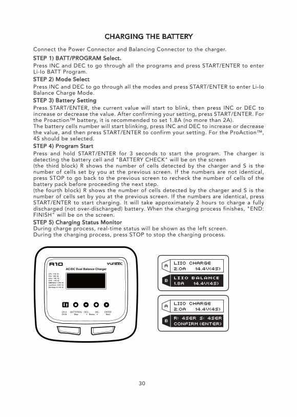
CHARGING THE BATTERY
Connect the Power Connector and Balancing Connector to the charger.STEP 1) BATT/PROGRAM Select.Press INC and DEC to go through all the programs and press START/ENTER to enter Li-Io BATT Program.STEP 2) Mode SelectPress INC and DEC to go through all the modes and press START/ENTER to enter Li-Io Balance Charge Mode.STEP 3) Battery SettingPress START/ENTER, the current value will start to blink, then press INC or DEC to increase or decrease the value. After confirming your setting, press START/ENTER. For the Proaction™ battery, it is recommended to set 1.8A (no more than 2A).The battery cells number will start blinking, press INC and DEC to increase or decrease the value, and then press START/ENTER to confirm your setting. For the ProAction™, 4S should be selected.STEP 4) Program StartPress and hold START/ENTER for 3 seconds to start the program. The charger is detecting the battery cell and "BATTERY CHECK" will be on the screen(the third block) R shows the number of cells detected by the charger and S is the number of cells set by you at the previous screen. If the numbers are not identical, press STOP to go back to the previous screen to recheck the number of cells of the battery pack before proceeding the next step.(the fourth block) R shows the number of cells detected by the charger and S is the number of cells set by you at the previous screen. If the numbers are identical, press START/ENTER to start charging. It will take approximately 2 hours to charge a fully discharged (not over-discharged) battery. When the charging process finishes, "END: FINISH" will be on the screen.STEP 5) Charging Status MonitorDuring charge process, real-time status will be shown as the left screen.During the charging process, press STOP to stop the charging process.
30
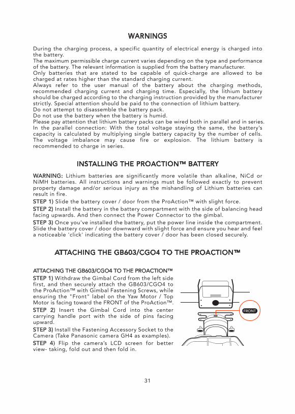
WARNINGS
During the charging process, a specific quantity of electrical energy is charged into the battery.The maximum permissible charge current varies depending on the type and performance of the battery. The relevant information is supplied from the battery manufacturer.Only batteries that are stated to be capable of quick-charge are allowed to be charged at rates higher than the standard charging current.Always refer to the user manual of the battery about the charging methods, recommended charging current and charging time. Especially, the lithium battery should be charged according to the charging instruction provided by the manufacturer strictly. Special attention should be paid to the connection of lithium battery.Do not attempt to disassemble the battery pack.Do not use the battery when the battery is humid.Please pay attention that lithium battery packs can be wired both in parallel and in series.In the parallel connection: With the total voltage staying the same, the battery’s capacity is calculated by multiplying single battery capacity by the number of cells. The voltage imbalance may cause fire or explosion. The lithium battery is recommended to charge in series.
INSTALLING THE PROACTION™ BATTERYWARNING: Lithium batteries are significantly more volatile than alkaline, NiCd or NiMH batteries. All instructions and warnings must be followed exactly to prevent property damage and/or serious injury as the mishandling of Lithium batteries can result in fire.STEP 1) Slide the battery cover / door from the ProAction™ with slight force.STEP 2) Install the battery in the battery compartment with the side of balancing head facing upwards. And then connect the Power Connector to the gimbal.STEP 3) Once you've installed the battery, put the power line inside the compartment. Slide the battery cover / door downward with slight force and ensure you hear and feel a noticeable 'click' indicating the battery cover / door has been closed securely.
ATTACHING THE GB603/CGO4 TO THE PROACTION™
ATTACHING THE GB603/CGO4 TO THE PROACTION™STEP 1) Withdraw the Gimbal Cord from the left side first, and then securely attach the GB603/CGO4 to the ProAction™ with Gimbal Fastening Screws, while ensuring the "Front" label on the Yaw Motor / Top Motor is facing toward the FRONT of the ProAction™.STEP 2) Insert the Gimbal Cord into the center carrying handle port with the side of pins facing upward.STEP 3) Install the Fastening Accessory Socket to the Camera (Take Panasonic camera GH4 as examples).STEP 4) Flip the camera’s LCD screen for better view- taking, fold out and then fold in.
31
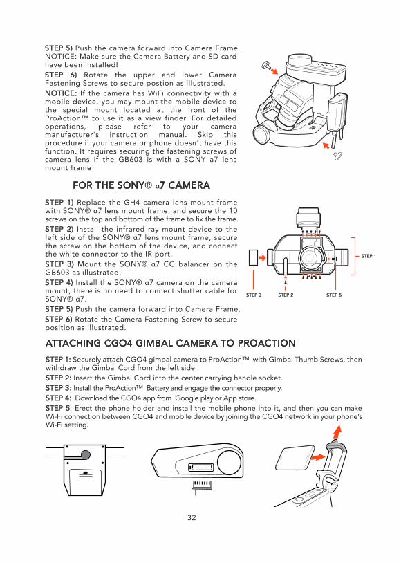
STEP 5) Push the camera forward into Camera Frame.NOTICE: Make sure the Camera Battery and SD card have been installed!STEP 6) Rotate the upper and lower Camera Fastening Screws to secure postion as illustrated.NOTICE: If the camera has WiFi connectivity with a mobile device, you may mount the mobile device to the special mount located at the front of the ProAction™ to use it as a view finder. For detailed operations, please refer to your camera manufacturer's instruction manual. Skip this procedure if your camera or phone doesn't have this function. It requires securing the fastening screws of camera lens if the GB603 is with a SONY a7 lens mount frame
32
FOR THE SONY® α7 CAMERA
STEP 1) Replace the GH4 camera lens mount frame with SONY® α7 lens mount frame, and secure the 10 screws on the top and bottom of the frame to fix the frame. STEP 2) Install the infrared ray mount device to the left side of the SONY® α7 lens mount frame, secure the screw on the bottom of the device, and connect the white connector to the IR port. STEP 3) Mount the SONY® α7 CG balancer on the GB603 as illustrated.STEP 4) Install the SONY® α7 camera on the camera mount, there is no need to connect shutter cable for SONY® α7.STEP 5) Push the camera forward into Camera Frame.STEP 6) Rotate the Camera Fastening Screw to secure position as illustrated.
STEP 1
STEP 2 STEP 5STEP 3
ATTACHING CGO4 GIMBAL CAMERA TO PROACTIONSTEP 1: Securely attach CGO4 gimbal camera to ProAction™ with Gimbal Thumb Screws, then withdraw the Gimbal Cord from the left side. STEP 2: Insert the Gimbal Cord into the center carrying handle socket.STEP 3: Install the ProAction™ Battery and engage the connector properly.STEP 4: Download the CGO4 app from Google play or App store.STEP 5: Erect the phone holder and install the mobile phone into it, and then you can make Wi-Fi connection between CGO4 and mobile device by joining the CGO4 network in your phone’s Wi-Fi setting.
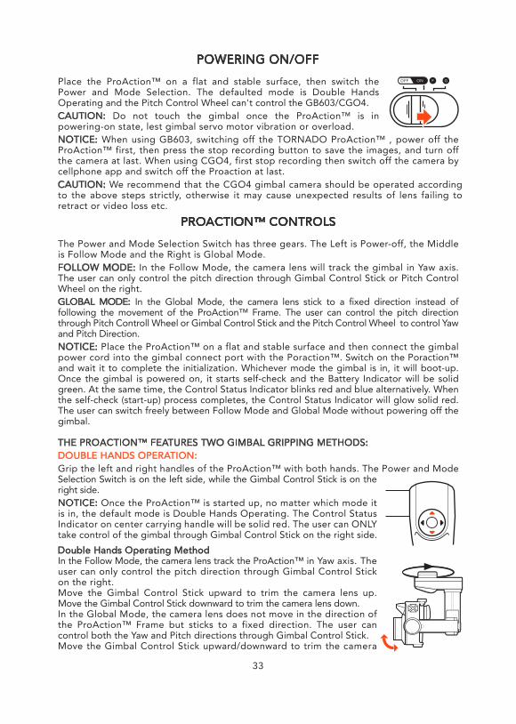
33
PROACTION™ CONTROLS
The Power and Mode Selection Switch has three gears. The Left is Power-off, the Middle is Follow Mode and the Right is Global Mode.FOLLOW MODE: In the Follow Mode, the camera lens will track the gimbal in Yaw axis. The user can only control the pitch direction through Gimbal Control Stick or Pitch Control Wheel on the right.GLOBAL MODE: In the Global Mode, the camera lens stick to a fixed direction instead of following the movement of the ProAction™ Frame. The user can control the pitch direction through Pitch Controll Wheel or Gimbal Control Stick and the Pitch Control Wheel to control Yaw and Pitch Direction.NOTICE: Place the ProAction™ on a flat and stable surface and then connect the gimbal power cord into the gimbal connect port with the Poraction™. Switch on the Poraction™ and wait it to complete the initialization. Whichever mode the gimbal is in, it will boot-up. Once the gimbal is powered on, it starts self-check and the Battery Indicator will be solid green. At the same time, the Control Status Indicator blinks red and blue alternatively. When the self-check (start-up) process completes, the Control Status Indicator will glow solid red. The user can switch freely between Follow Mode and Global Mode without powering off the gimbal.
THE PROACTION™ FEATURES TWO GIMBAL GRIPPING METHODS:DOUBLE HANDS OPERATION:Grip the left and right handles of the ProAction™ with both hands. The Power and Mode Selection Switch is on the left side, while the Gimbal Control Stick is on the right side.NOTICE: Once the ProAction™ is started up, no matter which mode it is in, the default mode is Double Hands Operating. The Control Status Indicator on center carrying handle will be solid red. The user can ONLY take control of the gimbal through Gimbal Control Stick on the right side.Double Hands Operating MethodIn the Follow Mode, the camera lens track the ProAction™ in Yaw axis. The user can only control the pitch direction through Gimbal Control Stick on the right.Move the Gimbal Control Stick upward to trim the camera lens up. Move the Gimbal Control Stick downward to trim the camera lens down.In the Global Mode, the camera lens does not move in the direction of the ProAction™ Frame but sticks to a fixed direction. The user can control both the Yaw and Pitch directions through Gimbal Control Stick.Move the Gimbal Control Stick upward/downward to trim the camera
POWERING ON/OFF
Place the ProAction™ on a flat and stable surface, then switch the Power and Mode Selection. The defaulted mode is Double Hands Operating and the Pitch Control Wheel can't control the GB603/CGO4.CAUTION: Do not touch the gimbal once the ProAction™ is in powering-on state, lest gimbal servo motor vibration or overload.NOTICE: When using GB603, switching off the TORNADO ProAction™ , power off the ProAction™ first, then press the stop recording button to save the images, and turn off the camera at last. When using CGO4, first stop recording then switch off the camera by cellphone app and switch off the Proaction at last.
OFF ON F G
CAUTION: We recommend that the CGO4 gimbal camera should be operated according to the above steps strictly, otherwise it may cause unexpected results of lens failing to retract or video loss etc.
lens up/down. Move the Gimbal Control Stick to the left/right to trim the camera lens left/right.NOTICE: When in the Follow Mode, the Gimbal Control Stick can't control the GB603/CGO4 in Yaw axis. When in the Global Mode, the Gimbal Control Stick can control the GB603/CGO4 in Pitch and Yaw axes.
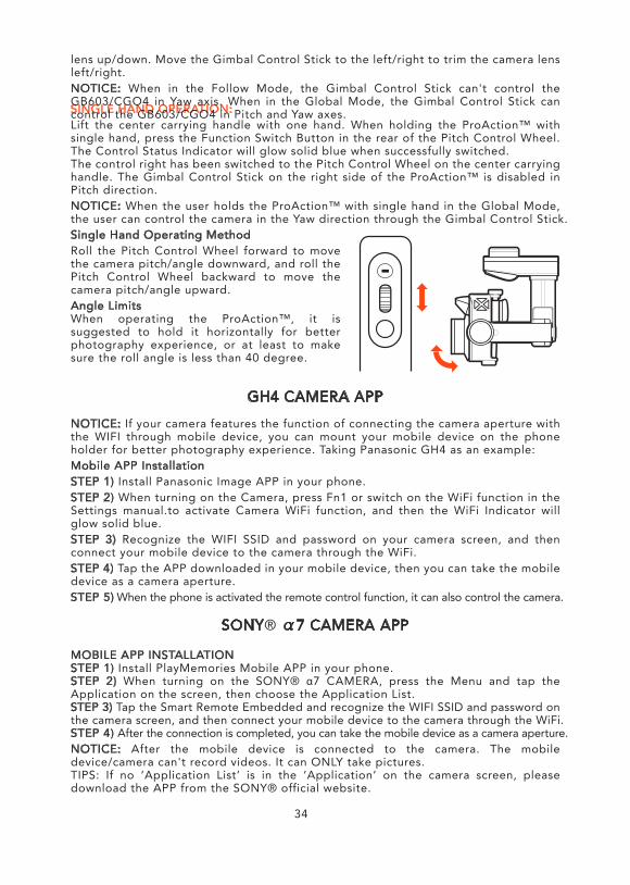
GH4 CAMERA APP
NOTICE: If your camera features the function of connecting the camera aperture with the WIFI through mobile device, you can mount your mobile device on the phone holder for better photography experience. Taking Panasonic GH4 as an example:Mobile APP InstallationSTEP 1) Install Panasonic Image APP in your phone.STEP 2) When turning on the Camera, press Fn1 or switch on the WiFi function in the Settings manual.to activate Camera WiFi function, and then the WiFi Indicator will glow solid blue.STEP 3) Recognize the WIFI SSID and password on your camera screen, and then connect your mobile device to the camera through the WiFi.STEP 4) Tap the APP downloaded in your mobile device, then you can take the mobile device as a camera aperture.STEP 5) When the phone is activated the remote control function, it can also control the camera.
SINGLE HAND OPERATION:Lift the center carrying handle with one hand. When holding the ProAction™ with single hand, press the Function Switch Button in the rear of the Pitch Control Wheel. The Control Status Indicator will glow solid blue when successfully switched.The control right has been switched to the Pitch Control Wheel on the center carrying handle. The Gimbal Control Stick on the right side of the ProAction™ is disabled in Pitch direction.NOTICE: When the user holds the ProAction™ with single hand in the Global Mode, the user can control the camera in the Yaw direction through the Gimbal Control Stick.Single Hand Operating MethodRoll the Pitch Control Wheel forward to move the camera pitch/angle downward, and roll the Pitch Control Wheel backward to move the camera pitch/angle upward.Angle LimitsWhen operating the ProAction™, it is suggested to hold it horizontally for better photography experience, or at least to make sure the roll angle is less than 40 degree.
34
SONY® α7 CAMERA APP
MOBILE APP INSTALLATIONSTEP 1) Install PlayMemories Mobile APP in your phone.STEP 2) When turning on the SONY® α7 CAMERA, press the Menu and tap the Application on the screen, then choose the Application List.STEP 3) Tap the Smart Remote Embedded and recognize the WIFI SSID and password on the camera screen, and then connect your mobile device to the camera through the WiFi.STEP 4) After the connection is completed, you can take the mobile device as a camera aperture.NOTICE: After the mobile device is connected to the camera. The mobile device/camera can't record videos. It can ONLY take pictures.TIPS: If no ‘Application List’ is in the ‘Application’ on the camera screen, please download the APP from the SONY® official website.
PROACTION™ CONTROLS
The Power and Mode Selection Switch has three gears. The Left is Power-off, the Middle is Follow Mode and the Right is Global Mode.FOLLOW MODE: In the Follow Mode, the camera lens will track the gimbal in Yaw axis. The user can only control the pitch direction through Gimbal Control Stick or Pitch Control Wheel on the right.GLOBAL MODE: In the Global Mode, the camera lens stick to a fixed direction instead of following the movement of the ProAction™ Frame. The user can control the pitch direction through Pitch Controll Wheel or Gimbal Control Stick and the Pitch Control Wheel to control Yaw and Pitch Direction.NOTICE: Place the ProAction™ on a flat and stable surface and then connect the gimbal power cord into the gimbal connect port with the Poraction™. Switch on the Poraction™ and wait it to complete the initialization. Whichever mode the gimbal is in, it will boot-up. Once the gimbal is powered on, it starts self-check and the Battery Indicator will be solid green. At the same time, the Control Status Indicator blinks red and blue alternatively. When the self-check (start-up) process completes, the Control Status Indicator will glow solid red. The user can switch freely between Follow Mode and Global Mode without powering off the gimbal.
THE PROACTION™ FEATURES TWO GIMBAL GRIPPING METHODS:DOUBLE HANDS OPERATION:Grip the left and right handles of the ProAction™ with both hands. The Power and Mode Selection Switch is on the left side, while the Gimbal Control Stick is on the right side.NOTICE: Once the ProAction™ is started up, no matter which mode it is in, the default mode is Double Hands Operating. The Control Status Indicator on center carrying handle will be solid red. The user can ONLY take control of the gimbal through Gimbal Control Stick on the right side.Double Hands Operating MethodIn the Follow Mode, the camera lens track the ProAction™ in Yaw axis. The user can only control the pitch direction through Gimbal Control Stick on the right.Move the Gimbal Control Stick upward to trim the camera lens up. Move the Gimbal Control Stick downward to trim the camera lens down.In the Global Mode, the camera lens does not move in the direction of the ProAction™ Frame but sticks to a fixed direction. The user can control both the Yaw and Pitch directions through Gimbal Control Stick.Move the Gimbal Control Stick upward/downward to trim the camera
lens up/down. Move the Gimbal Control Stick to the left/right to trim the camera lens left/right.NOTICE: When in the Follow Mode, the Gimbal Control Stick can't control the GB603/CGO4 in Yaw axis. When in the Global Mode, the Gimbal Control Stick can control the GB603/CGO4 in Pitch and Yaw axes.
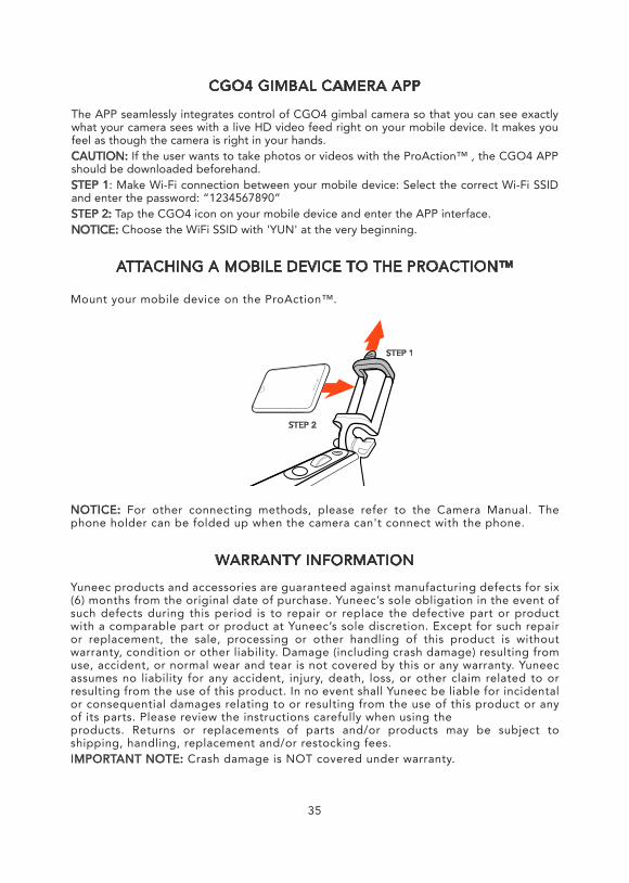
ATTACHING A MOBILE DEVICE TO THE PROACTION™
Mount your mobile device on the ProAction™.
NOTICE: For other connecting methods, please refer to the Camera Manual. The phone holder can be folded up when the camera can't connect with the phone.
WARRANTY INFORMATION
Yuneec products and accessories are guaranteed against manufacturing defects for six (6) months from the original date of purchase. Yuneec’s sole obligation in the event of such defects during this period is to repair or replace the defective part or product with a comparable part or product at Yuneec’s sole discretion. Except for such repair or replacement, the sale, processing or other handling of this product is without warranty, condition or other liability. Damage (including crash damage) resulting from use, accident, or normal wear and tear is not covered by this or any warranty. Yuneec assumes no liability for any accident, injury, death, loss, or other claim related to or resulting from the use of this product. In no event shall Yuneec be liable for incidental or consequential damages relating to or resulting from the use of this product or any of its parts. Please review the instructions carefully when using theproducts. Returns or replacements of parts and/or products may be subject to shipping, handling, replacement and/or restocking fees.IMPORTANT NOTE: Crash damage is NOT covered under warranty.
STEP 1
STEP 2
35
CGO4 GIMBAL CAMERA APP
The APP seamlessly integrates control of CGO4 gimbal camera so that you can see exactly what your camera sees with a live HD video feed right on your mobile device. It makes you feel as though the camera is right in your hands. CAUTION: If the user wants to take photos or videos with the ProAction™ , the CGO4 APP should be downloaded beforehand.STEP 1: Make Wi-Fi connection between your mobile device: Select the correct Wi-Fi SSID and enter the password: “1234567890”STEP 2: Tap the CGO4 icon on your mobile device and enter the APP interface.NOTICE: Choose the WiFi SSID with 'YUN' at the very beginning.
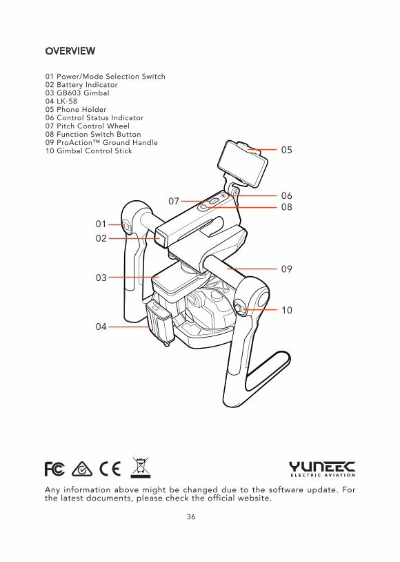
Any information above might be changed due to the software update. For the latest documents, please check the official website.
OVERVIEW
01 Power/Mode Selection Switch02 Battery Indicator03 GB603 Gimbal04 LK-5805 Phone Holder06 Control Status Indicator07 Pitch Control Wheel08 Function Switch Button09 ProAction™ Ground Handle10 Gimbal Control Stick
0102
03
04
05
0607 08
09
10
36
CERTIFICATION INFORMATION
FCC STATEMENT:This equipment has been tested and found to comply with the limits for Part 15 of the FCC rules. These limits are designed to provide reasonable protection against harmful interference in a residential installation. This equipment generates, uses and can radiate radio frequency energy and, if not installed and used in accordance with the instructions, may cause harmful interference to radio communications.However, there is no guarantee that interference will not occur in a particular installation. If this equipment does cause harmful interference to radio or television reception, which can be determined by turning the equipment off and on, the user is encouraged to try to correct the interference by one or more of the following measures:Reorient or relocate the receiving antenna.Increase the separation between the equipment and receiver.Connect the equipment to an outlet on a circuit different from that to which the receiver is connected.This device complies with part 15 of the FCC rules. Operation is subject to the following two conditions:(1) This device may not cause harmful interference, and (2) this device must accept any interference received, including interference that may cause undesired operation.NOTE: This equipment has been tested and found to comply with the limits for a Class B digital device, pursuant to part 15 of the FCC Rules. These limits are designed to provide reasonable protection against harmful interference in a residential installation. This equipment generates, uses and can radiate radio frequency energy and, if not installed and used in accordance with the instructions, may cause harmful interference to radio communications. However,there is no guarantee that interference will not occur in a particular installation. If this equipment does cause harmful interference to radio or television reception, which can be determined by turning the equipment off and on, the user is encouraged to try to correct the interference by one or more of the following measures:—Reorient or relocate the receiving antenna.—Increase the separation between the equipment and receiver.—Connect the equipment into an outlet on a circuit different from that to which the receiver is connected.—Consult the dealer or an experienced radio/TV technician for help.RF EXPOSURE WARNINGThis equipment must be installed and operated in accordance with provided instructions and the antenna(s) used for this transmitter must be installed to provide a separation distance of at least 20 cm from all persons and must not be co-located or operating in conjunction with any other antenna or transmitter. End-users and installers must be provide with antenna installation instructions and transmitter operating conditions for satisfying RF exposure compliance.IC RADIATION EXPOSURE STATEMENT FOR CANADAThis device complies with Industry Canada license-exempt RSS standard(s).Operation is subject to the following two conditions: (1) this device may not cause interference, and (2) this device must accept any interference, including interference that may cause undesired operation of the device.Le présent appareil est conforme aux CNR d'Industrie Canada applicables aux appareils radio exempts de licence. L'exploitation est autorisée aux deux conditions suivantes : (1) l'appareil ne doit pas produire de brouillage, et (2) l'utilisateur de l'appareil doit accepter tout brouillage radioélectrique subi, même si le brouillage est susceptible d'en compromettre le fonctionnement.This equipment complies with IC RSS-102 radiation exposure limit set forth for an uncontrolled environment.Cet équipement respecte les limites d'exposition aux rayonnements IC définies pour un environnement non contrôlé
37