Embed Size (px)
Citation preview
Preface
PrefaceCopyrightThis publication, including all photographs, illustrations and software, is protectedunder international copyright laws, with all rights reserved. Neither this manual, norany of the material contained herein, may be reproduced without written consent ofthe author.
Version 1.0
DisclaimerThe information in this document is subject to change without notice. The manufac-turer makes no representations or warranties with respect to the contents hereof andspecifically disclaims any implied warranties of merchantability or fitness for anyparticular purpose. The manufacturer reserves the right to revise this publication andto make changes from time to time in the content hereof without obligation of themanufacturer to notify any person of such revision or changes.
Trademark RecognitionMicrosoft, MS-DOS and Windows are registered trademarks of Microsoft Corp.
MMX, Pentium, Pentium-II, Pentium-III, Celeron are registered trademarks of IntelCorporation.
Other product names used in this manual are the properties of their respectiveowners and are acknowledged.
Federal Communications Commission (FCC)This equipment has been tested and found to comply with the limits for a Class Bdigital device, pursuant to Part 15 of the FCC Rules. These limits are designed toprovide reasonable protection against harmful interference in a residential installa-tion. This equipment generates, uses, and can radiate radio frequency energy and, ifnot installed and used in accordance with the instructions, may cause harmful inter-ference to radio communications. However, there is no guarantee that interferencewill not occur in a particular installation. If this equipment does cause harmfulinterference to radio or television reception, which can be determined by turning theequipment off and on, the user is encouraged to try to correct the interference by oneor more of the following measures:
• Reorient or relocate the receiving antenna• Increase the separation between the equipment and the receiver• Connect the equipment onto an outlet on a circuit different from that to
which the receiver is connected• Consult the dealer or an experienced radio/TV technician for help
Shielded interconnect cables and a shielded AC power cable must be employed withthis equipment to ensure compliance with the pertinent RF emission limits governingthis device. Changes or modifications not expressly approved by the system’s manu-facturer could void the user’s authority to operate the equipment.
ii
Preface
Declaration of ConformityThis device complies with part 15 of the FCC rules. Operation is subject to thefollowing conditions:
• This device may not cause harmful interference.• This device must accept any interference received, including interfer-
ence that may cause undesired operation.
Canadian Department of CommunicationsThis class B digital apparatus meets all requirements of the Canadian Interference-causing Equipment Regulations.Cet appareil numérique de la classe B respecte toutes les exigences du Réglement surle matériel brouilieur du Canada.
About the ManualThe manual consists of the following:
Describes features of themotherboard.
Go to page 1
Describes installation ofmotherboard components.
Go to page 7
Go to page 25
Go to page 59
Describes the motherboardsoftware
Chapter 2
Installing the Motherboard
Chapter 1
Introducing the Motherboard
Chapter 3
Using BIOS
Chapter 4
Using the Motherboard Software
Chapter 5Trouble Shooting
Provides basic trouble shoot-ing tips
page 63Go to
Provides information on usingthe BIOS Setup Utility.
iii
Chapter 2 7 7 7 7 7Installing the Motherboard 7
Safety Precautions............................................................................7Choosing a Computer Case.............................................................7Installing the Motherboard in a Case............................................7Checking Jumper Settings...............................................................8 Setting Jumpers........................................................................8 Checking Jumper Settings........................................................9
Jumper Settings........................................................................9 Installing Hardware...................................................................10
Installing the Processor..........................................................10 Installing Memory Modules...................................................12 Expansion Slots......................................................................14 Connecting Optional Devices.................................................16
Installing a SATA Hard Drive................................................19 Connecting I/O Devices............................................................... 20Connecting Case Components.....................................................21
Front Panel Header................................................................24
TTTTTABLE OF CONTENTSABLE OF CONTENTSABLE OF CONTENTSABLE OF CONTENTSABLE OF CONTENTS
Preface i
Chapter 1 1Introducing the Motherboard 1
Introduction...................................................................................1 Feature............................................................................................2 Specifications................................................................................4 Motherboard Components..........................................................5
Chapter 3 25Using BIOS 25
About the Setup Utility........................ ......................................... 25 The Standard Configuration........................ ...........................25
Entering the Setup Utilities......................................................25Resetting the Default CMOS Values....................................26
Using BIOS......................................................................................26 BIOS Navigation Key.............................................................27
Main Menu.............................................................................28 Advanced Menu......................................................................29
Chipset Menu..........................................................................40 M.I.B.III(MB Intelligent Bios III) Menu..................................47 Boot Menu...............................................................................53
iv
Security Menu.........................................................................54 Exit Menu...............................................................................55 Updating the BIOS..................................................................57
Chapter 4 59 59 59 59 59Using the Motherboard Software 59
About the Software DVD-ROM/CD-ROM...................................59Auto-installing under Windows XP/Vista/7..................................59 Running Setup.........................................................................60Manual Installation...........................................................................62Utility Software Reference.................................................................62
Chapter 6 63 63 63 63 63Trouble Shooting 63
Start up problems during assembly..............................................63Start up problems after prolong use............................................64Maintenance and care tips..............................................................64Basic Troubleshooting Flowchart...................................................65
1
Introducing the Motherboard
Chapter 1Introducing the Motherboard
IntroductionThank you for choosing the H61H2-M12 motherboard. This motherboard is a highperformance, enhanced function motherboard designed to support the LGA1155socket for new 2nd Generation Intel CoreTM i7/i5/i3 series processor/Intel Pentium/Celeron processors for high-end business or personal desktop markets.
This motherboard is based on Intel H61 Express Chipset for best desktop platformsolution. H61 is a single-chip, highly integrated, high performance Hyper-Threadingperipheral controller, unmatched by any other single chip-device controller. Thismotherboard supports up to 16 GB of system memory with dual channel DDR3 1333/1066 SDRAM. High resolution graphics via PCI Express x16 slot, intended forGraphics Interface, is fully compliant to the PCI Express Base Specification revision2.0. In addition, two PCI Express slots are supported. It implements an EHCI (En-hanced Host Controller Interface) compliant interface that provides eight USB 2.0ports (four USB 2.0 ports at the back panel and two USB 2.0 headers supportadditional four USB 2.0 ports).
The motherboard is equipped with advanced full set of I/O ports in the rear panel,including PS/2 mouse and PS/2 keyboard connectors, one D_sub (VGA) port, oneLAN port, four USB 2.0 ports, and audio jacks for microphone, line-in and line-out.
In addition, this motherboard supports four SATA 3.0Gb/s connectors for expansion.
2
Introducing the Motherboard
Feature
• Accommodates new 2nd Generation Intel CoreTM i7/i5/i3 series processor/Intel Pentium /Celeron processors
• Supports “Hyper-Threading” technology CPU• One PCI Express x16 Gen2 port supporting up to 5 GB/s direction peak
bandwidth “Hyper-Threading” technology enables the operating system into thinking it’s hooked up to two processors, allowing two threads to be run in parallel, both on separate “logical” processors within the same physical processor.
The motherboard uses an LGA1155 type of socket that carries the followingfeatures:
Processor
Chipset
• Supports DDR3 1333/1066 DDR3 SDRAM with Dual-channel architec-ture
• Accommodates two unbuffered DIMMs• Up to 8 GB per DIMM with maximum memory size up to 16 GB
Memory
Audio • 5.1+2 Channel High Definition Audio Codec • Meets Microsoft WLP3.x (Windows Logo Program) audio
requirements • All DACs supports 44.1k/48k/96k/192kHz sample rate • Software selectable 2.5V/3.2V/4.0V VREFOUT • Direct Sound 3D. compatible • Power Support: Digital: 3.3V; Analog: 5.0V
The Intel H61 Chipset is a single-chip with proven reliability and performance.• Support two PCI Express x1 slots• Integrated four SATA 3.0 Gb/s Host Controller• Eight USB 2.0 ports supported• Serial Peripheral Interface (SPI) support• Integrated Graphics Support with PAVP 1.5• Intel® High Definition Audio Controller
3
Introducing the Motherboard
The motherboard comes with the following expansion options:
• One PCI Express x16 slot for Graphic Interface• Two PCI Express x1 slots• Four SATA 3.0 Gb/s connectors
Expansion Options
The motherboard has a full set of I/O ports and connectors:
Integrated I/O
• One LAN port• One D-sub (VGA) port• Four USB 2.0 ports• One PS/2 keyboard and PS/2 mouse connectors• Audio jacks for microphone, line-in and 6-ch line-out
The firmware can also be used to set parameters for different processor clockspeeds.
• Power management• Wake-up alarms• CPU parameters• CPU and memory timing• Graphic parameters
BIOS FirmwareThis motherboard uses AMI BIOS that enables users to configure many systemfeatures including the following:
1. Some hardware specifications and software items are subject to changewithout prior notice.2. Due to chipset limitation, we recommend that motherboard be operatedin the ambiance between 0 and 50 ° C.
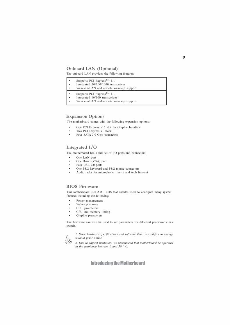
Onboard LAN (Optional)The onboard LAN provides the following features:
• Supports PCI ExpressTM 1.1• Integrated 10/100 transceiver• Wake-on-LAN and remote wake-up support
• Supports PCI ExpressTM 1.1• Integrated 10/100/1000 transceiver• Wake-on-LAN and remote wake-up support
4
Introducing the Motherboard
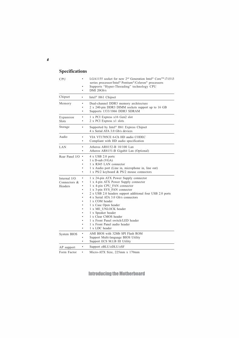
• LGA1155 socket for new 2nd Generation Intel CoreTM i7/i5/i3series processor/Intel Pentium /Celeron processors
• Supports “Hyper-Threading” technology CPU• DMI 20Gb/s
CPU
Specifications
• AMI BIOS with 32Mb SPI Flash ROM• Support Multi-language BIOS Utility• Support ECS M.I.B III Utility
Form Factor • Micro-ATX Size, 225mm x 170mm
System BIOS
• Support eBLU/eDLU/eSFAP support
• Intel H61 ChipsetChipset
• Dual-channel DDR3 memory architecture• 2 x 240-pin DDR3 DIMM sockets support up to 16 GB• Supports 1333/1066 DDR3 SDRAM
• 1 x PCI Express x16 Gen2 slot• 2 x PCI Express x1 slots
• Supported by Intel H61 Express Chipset4 x Serial ATA 3.0 Gb/s devices
• VIA VT1705CE 6-Ch HD audio CODEC• Compliant with HD audio specification
• 4 x USB 2.0 ports• 1 x D-sub (VGA)• 1 x RJ45 LAN connector• 1 x Audio port (Line in, microphone in, line out)• 1 x PS/2 keyboard & PS/2 mouse connectors
Memory
ExpansionSlots
Storage
LAN
Rear Panel I/O
• Atheros AR8152-B 10/100 Lan• Atheros AR8151-B Gigabit Lan (Optional)
Audio
• 1 x 24-pin ATX Power Supply connector• 1 x 4-pin ATX Power Supply connector• 1 x 4-pin CPU_FAN connector• 1 x 3-pin SYS_FAN connector• 2 x USB 2.0 headers support additional four USB 2.0 ports• 4 x Serial ATA 3.0 Gb/s connectors• 1 x COM header• 1 x Case Open header• 1 x ME_UNLOCK header• 1 x Speaker header• 1 x Clear CMOS header• 1 x Front Panel switch/LED header• 1 x Front Panel audio header• 1 x LDC header
Internal I/OConnectors &Headers
5
Introducing the Motherboard
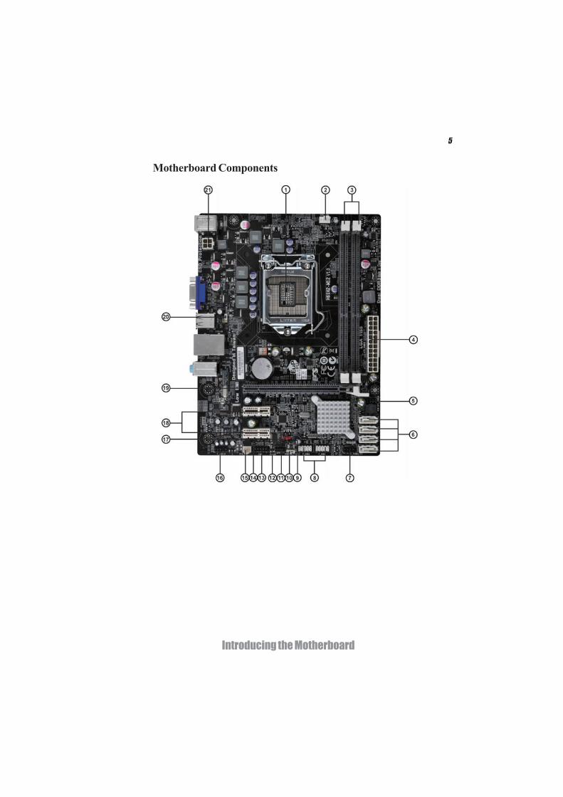
Motherboard Components
6
Introducing the Motherboard
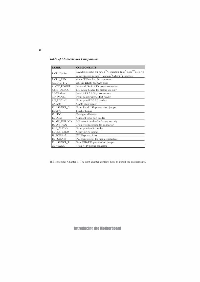
Table of Motherboard Components
This concludes Chapter 1. The next chapter explains how to install the motherboard.
LABEL COMPONENTS
LGA1155 socket for new 2nd Generation Intel CoreTM i7/i5/i3series processor/Intel Pentium Celeron processors
2. CPU_FAN 4-pin CPU cooling fan connector3. DDR3_1~2 240-pin DDR3 SDRAM slots4. ATX_POWER Standard 24-pin ATX power connector5. SPI_DEBUG SPI debug header-for factory use only6. SATA1~4 Serial ATA 3.0 Gb/s connectors7. F_PANEL Front panel switch/LED header8. F_USB1~2 Front panel USB 2.0 headers 9. CASE CASE open header10. USBPWR_F1 Front Panel USB power select jumper11. SPK Speaker header12. LDC Debug card header13. COM Onboard serial port header14. ME_UNLOCK ME unlock header-for factory use only15. SYS_FAN 3-pin system cooling fan connector16. F_AUDIO Front panel audio header17. CLR_CMOS Clear CMOS jumper18. PCIE1~2 PCI Express x1 slot19. PCIEX16 PCI Express slot for graphics interface20. USBPWR_R1 Rear USB/PS2 power select jumper21. ATX12V 4-pin +12V power connector
1. CPU Socket
7
Installing the Motherboard
Chapter 2Installing the Motherboard
Safety Precautions• Follow these safety precautions when installing the motherboard• Wear a grounding strap attached to a grounded device to avoid dam-
age from static electricity• Discharge static electricity by touching the metal case of a safely
grounded object before working on the motherboard• Leave components in the static-proof bags they came in• Hold all circuit boards by the edges. Do not bend circuit boards
Choosing a Computer CaseThere are many types of computer cases on the market. The motherboard complieswith the specifications for the Micro-ATX system case. Some features on themotherboard are implemented by cabling connectors on the motherboard to indica-tors and switches on the system case. Make sure that your case supports all thefeatures required.
Most cases have a choice of I/O templates in the rear panel. Make sure that the I/Otemplate in the case matches the I/O ports installed on the rear edge of themotherboard.
This motherboard carries a Micro-ATX form factor of 225 x 170 mm. Choose a casethat accommodates this form factor.
Installing the Motherboard in a CaseRefer to the following illustration and instructions for installing the motherboard ina case.Most system cases have mounting brackets installed in the case, which correspondthe holes in the motherboard. Place the motherboard over the mounting bracketsand secure the motherboard onto the mounting brackets with screws.Ensure that your case has an I/O template that supports the I/O ports and expansionslots on your motherboard.
8
Installing the Motherboard
Checking Jumper SettingsThis section explains how to set jumpers for correct configuration of the motherboard.
Setting JumpersUse the motherboard jumpers to set system configuration options. Jumpers withmore than one pin are numbered. When setting the jumpers, ensure that the jumpercaps are placed on the correct pins.
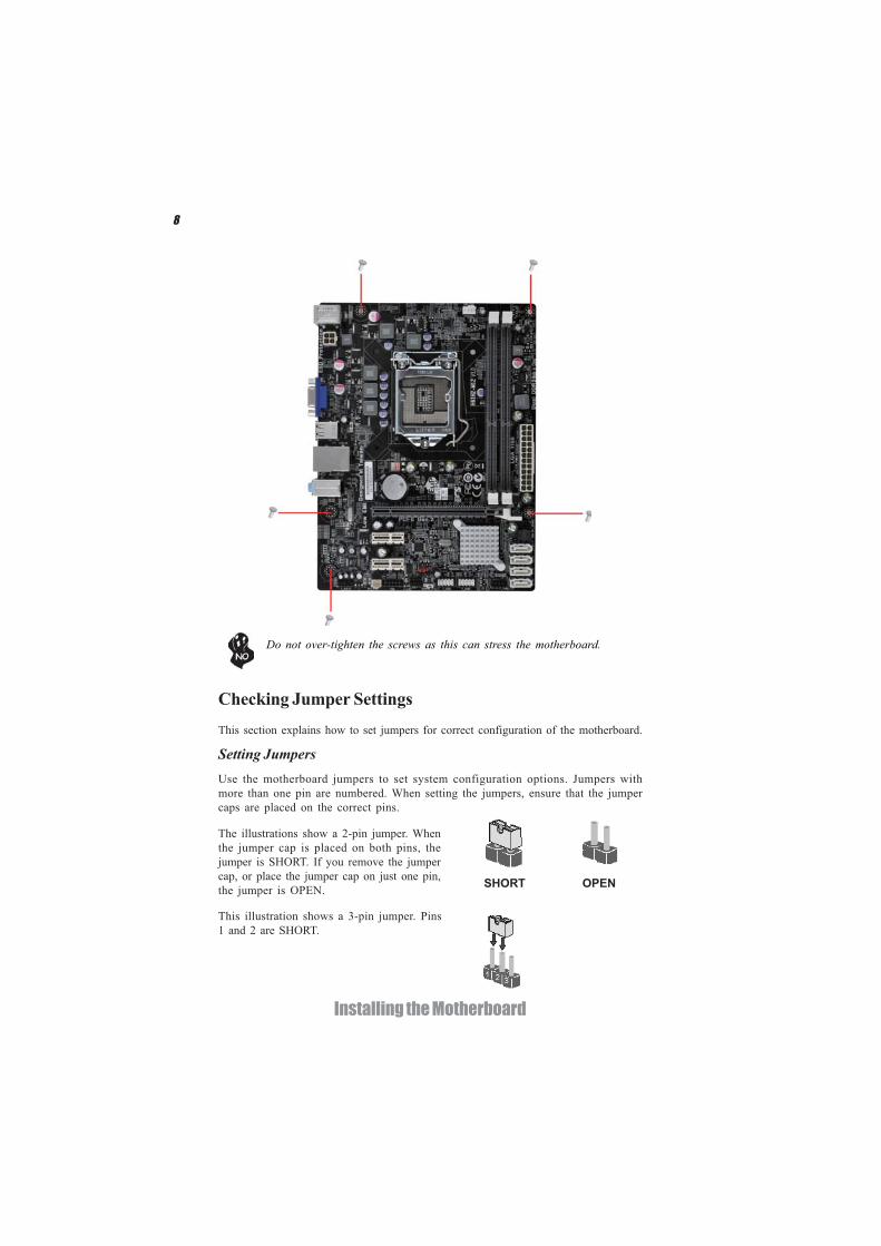
The illustrations show a 2-pin jumper. Whenthe jumper cap is placed on both pins, thejumper is SHORT. If you remove the jumpercap, or place the jumper cap on just one pin,the jumper is OPEN.
This illustration shows a 3-pin jumper. Pins1 and 2 are SHORT.
SHORT OPEN
Do not over-tighten the screws as this can stress the motherboard.
9
Installing the Motherboard
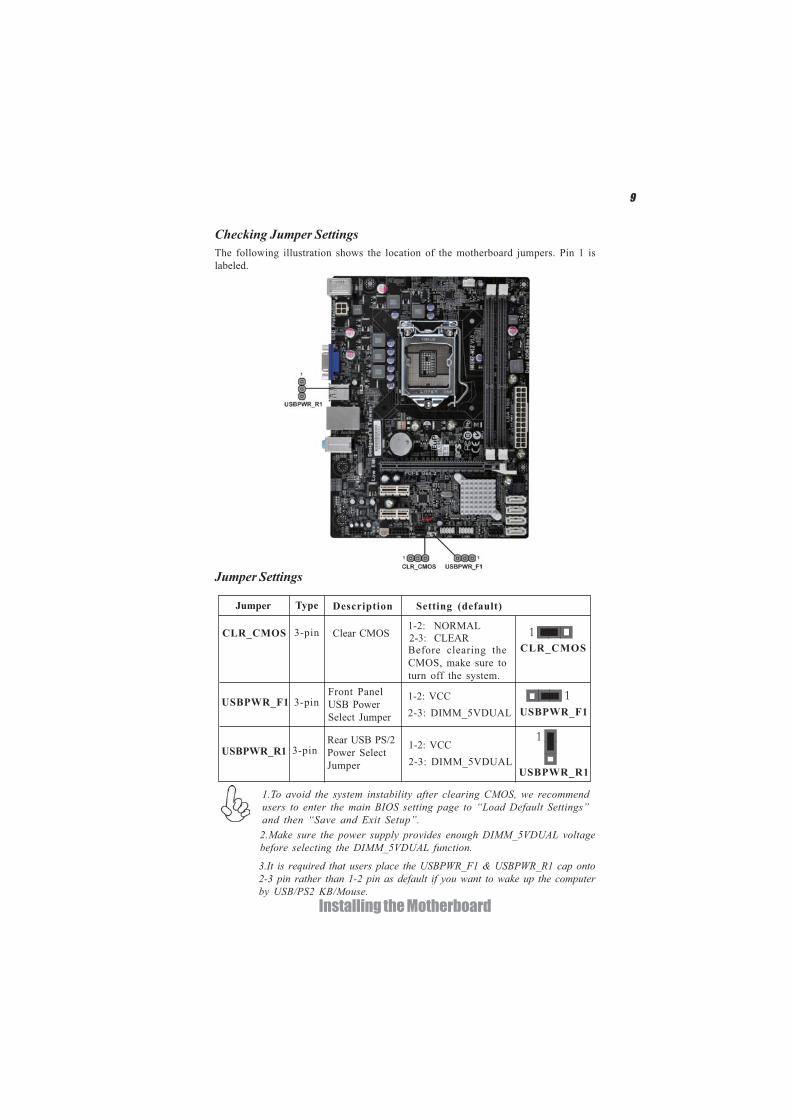
Checking Jumper SettingsThe following illustration shows the location of the motherboard jumpers. Pin 1 islabeled.
Jumper Settings
1.To avoid the system instability after clearing CMOS, we recommendusers to enter the main BIOS setting page to “Load Default Settings”and then “Save and Exit Setup”.
Jumper Type Description Setting (default)
CLR_CMOS 3-pin Clear CMOS1-2: NORMAL
Before clearing theCMOS, make sure toturn off the system.
Front PanelUSB PowerSelect Jumper USBPWR_F1
Rear USB PS/2Power SelectJumper
USBPWR_F1
USBPWR_R1
3-pin
3-pin
USBPWR_R1
1
1
2-3: CLEARCLR_CMOS
1
3.It is required that users place the USBPWR_F1 & USBPWR_R1 cap onto2-3 pin rather than 1-2 pin as default if you want to wake up the computerby USB/PS2 KB/Mouse.
2.Make sure the power supply provides enough DIMM_5VDUAL voltagebefore selecting the DIMM_5VDUAL function.
1-2: VCC2-3: DIMM_5VDUAL
1-2: VCC2-3: DIMM_5VDUAL
10
Installing the Motherboard
Installing HardwareInstalling the Processor
Caution: When installing a CPU heatsink and cooling fan make sure thatyou DO NOT scratch the motherboard or any of the surface-mount resis-tors with the clip of the cooling fan. If the clip of the cooling fan scrapesacross the motherboard, you may cause serious damage to the motherboardor its components.
On most motherboards, there are small surface-mount resistors near theprocessor socket, which may be damaged if the cooling fan is carelesslyinstalled.
Avoid using cooling fans with sharp edges on the fan casing and the clips.Also, install the cooling fan in a well-lit work area so that you can clearlysee the motherboard and processor socket.
Before installing the ProcessorThis motherboard automatically determines the CPU clock frequency and system busfrequency for the processor. You may be able to change the settings in the systemSetup Utility. We strongly recommend that you do not over-clock processors orother components to run faster than their rated speed.
This motherboard has an LGA1155 socket. When choosing a processor, consider theperformance requirements of the system. Performance is based on the processordesign, the clock speed and system bus frequency of the processor, and the quantityof internal cache memory and external cache memory.
Warning:
1. Over-clocking components can adversely affect the reliability of thesystem and introduce errors into your system. Over-clocking can perma-nently damage the motherboard by generating excess heat in componentsthat are run beyond the rated limits.
2. Always remove the AC power by unplugging the power cord from thepower outlet before installing or removing the motherboard or otherhardware components.
Fail-Safe Procedures for Over-clockingWhen end-users encounter failure after attempting over-clocking, please take thefollowing steps to recover from it.1. Shut down the computer.2. Press and hold the “Page Up Key (PgUp)” of the keyboard, and then boot the PCup.3. Two seconds after the PC boots up, release the “Page Up Key (PgUp)”.
4. The BIOS returns to the default setting by itself.

11
Installing the Motherboard
A. Disengaging of the Load Lever· Press the hook of lever down and pullit to the right side to release it fromretention tab.
B. Opening of the Load Plate· Lift the tail of the load lever.· Rotate the load plate to fully openposition.
C. Removing the Cap· Be careful not to touch the contact atany time.
D. Inserting the Package· Grasp the package. Ensure to graspon the edge of the substrate.· Make sure pin 1 indicator is on yourbottom-left side.· Aim at the socket and place thepackage carefully into the socket bypurely vertical motion.
E. Closing the Load Plate· Rotate the load plate onto the packageIHS (Intergraded Heat Spreader).· Engage the load lever while pressingdown lightly onto the load plate.· Secure the load lever with the hookunder retention tab.
F. Fasten the cooling fan supporting base onto the CPU socket on the motherboard.
G. Make sure the CPU fan is plugged to the CPU fan connector. Please refer to the CPU cooling fan user’s manual for more detail installation procedure.
CPU Installation ProcedureThe following illustration shows CPU installation components.
12
Installing the Motherboard
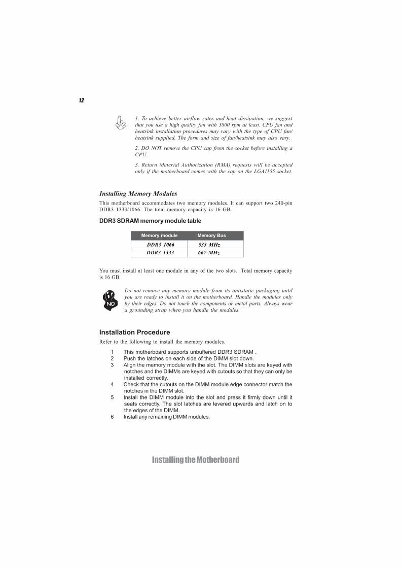
Installing Memory ModulesThis motherboard accommodates two memory modules. It can support two 240-pinDDR3 1333/1066. The total memory capacity is 16 GB.
You must install at least one module in any of the two slots. Total memory capacityis 16 GB.
DDR3 SDRAM memory module table
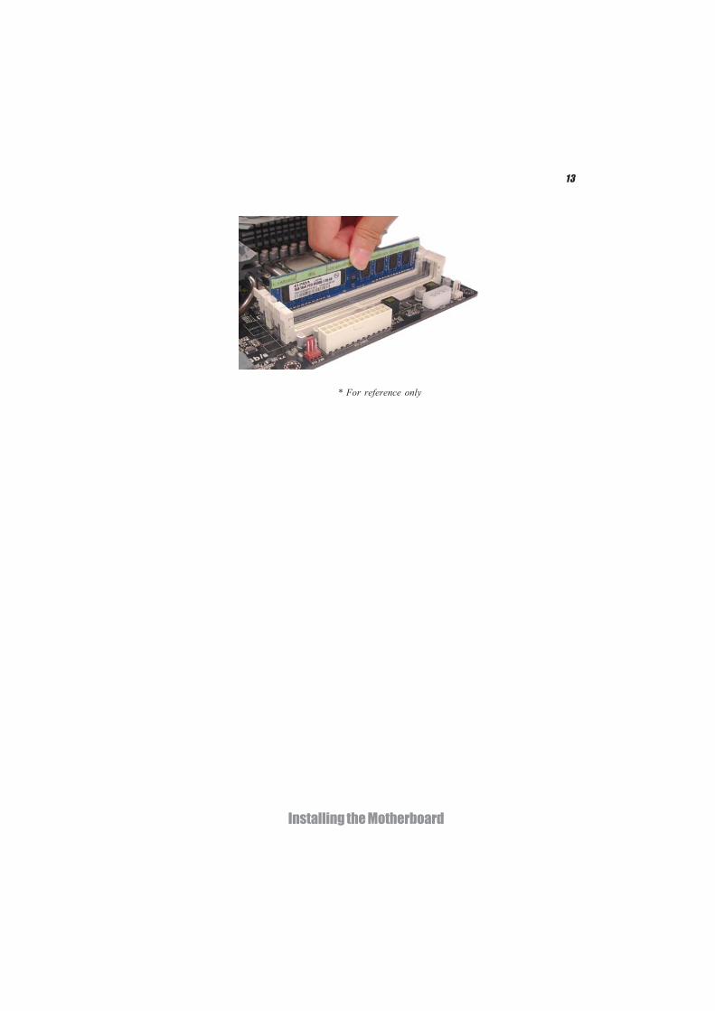
Installation ProcedureRefer to the following to install the memory modules.
1 This motherboard supports unbuffered DDR3 SDRAM .2 Push the latches on each side of the DIMM slot down.3 Align the memory module with the slot. The DIMM slots are keyed with
notches and the DIMMs are keyed with cutouts so that they can only beinstalled correctly.
4 Check that the cutouts on the DIMM module edge connector match thenotches in the DIMM slot.
5 Install the DIMM module into the slot and press it firmly down until itseats correctly. The slot latches are levered upwards and latch on tothe edges of the DIMM.
6 Install any remaining DIMM modules.
Do not remove any memory module from its antistatic packaging untilyou are ready to install it on the motherboard. Handle the modules onlyby their edges. Do not touch the components or metal parts. Always weara grounding strap when you handle the modules.
1. To achieve better airflow rates and heat dissipation, we suggestthat you use a high quality fan with 3800 rpm at least. CPU fan andheatsink installation procedures may vary with the type of CPU fan/heatsink supplied. The form and size of fan/heatsink may also vary.
2. DO NOT remove the CPU cap from the socket before installing aCPU.
3. Return Material Authorization (RMA) requests will be acceptedonly if the motherboard comes with the cap on the LGA1155 socket.
Memory module Memory Bus
DDR3 1066 533 MHzDDR3 1333 667 MHz
13
Installing the Motherboard
* For reference only

14
Installing the Motherboard
Installing Add-on CardsThe slots on this motherboard are designed to hold expansion cards and connect themto the system bus. Expansion slots are a means of adding or enhancing themotherboard’s features and capabilities. With these efficient facilities, you can in-crease the motherboard’s capabilities by adding hardware that performs tasks that arenot part of the basic system.
Before installing an add-on card, check the documentation for the cardcarefully. If the card is not Plug and Play, you may have to manuallyconfigure the card before installation.
Expansion Slots
The PCI Express x1 slots are fully compliant to the PCI Ex-press Base Specification revision 2.0.
PCIE1~2 Slots
PCIEX16 Slot The PCI Express x16 slot is used to install an external PCIExpress graphics card that is fully compliant to the PCI ExpressBase Specification revision 2.0.
15
Installing the Motherboard
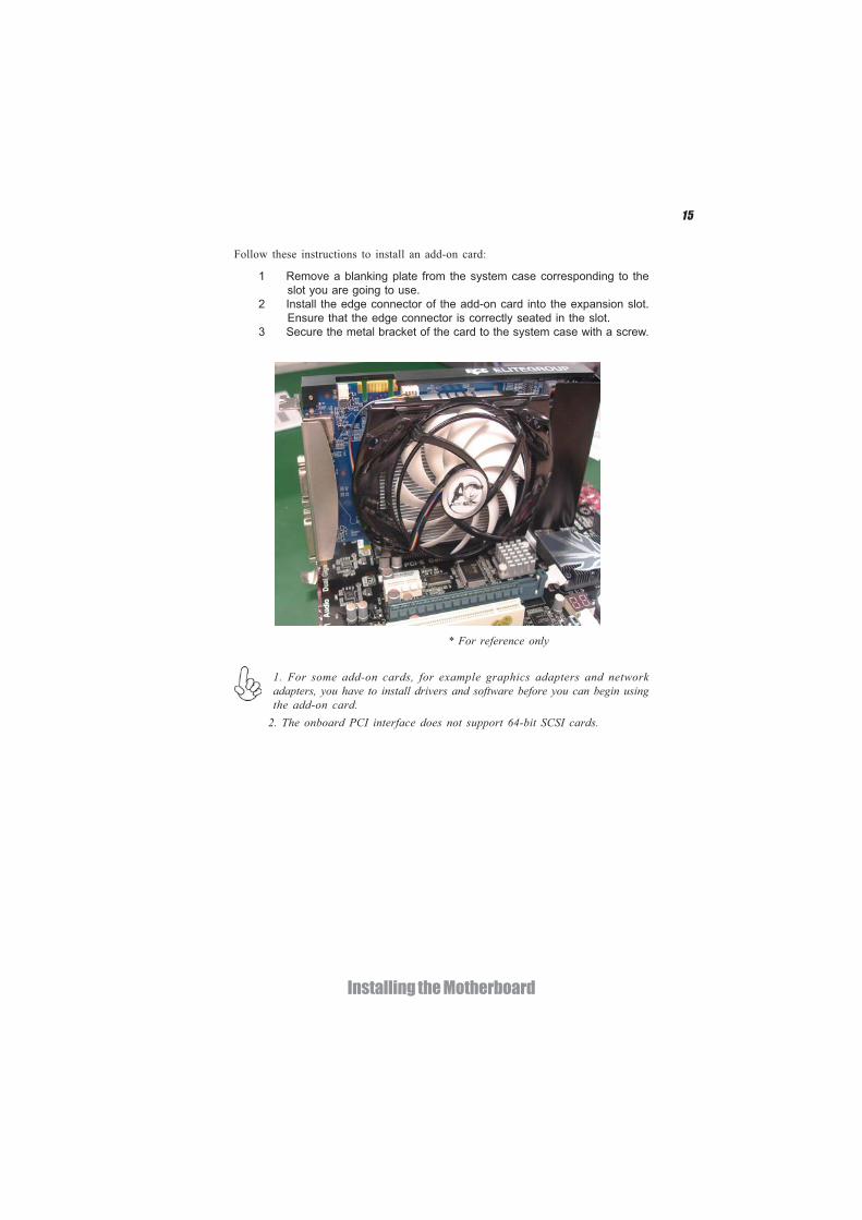
Follow these instructions to install an add-on card:
1 Remove a blanking plate from the system case corresponding to theslot you are going to use.
2 Install the edge connector of the add-on card into the expansion slot.Ensure that the edge connector is correctly seated in the slot.
3 Secure the metal bracket of the card to the system case with a screw.
2. The onboard PCI interface does not support 64-bit SCSI cards.
1. For some add-on cards, for example graphics adapters and networkadapters, you have to install drivers and software before you can begin usingthe add-on card.
* For reference only
16
Installing the Motherboard
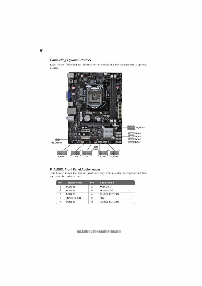
Connecting Optional DevicesRefer to the following for information on connecting the motherboard’s optionaldevices:
F_AUDIO: Front Panel Audio headerThis header allows the user to install auxiliary front-oriented microphone and line-out ports for easier access.
1 PORT 1L 2 AUD_GND
3 PORT 1R 4 PRESENCE#
5 PORT 2R 6 SENSE1_RETURN
7 SENSE_SEND 8 KEY
Pin Signal Name Pin Signal Name
9 PORT 2L 10 SENSE2_RETURN
17
Installing the Motherboard
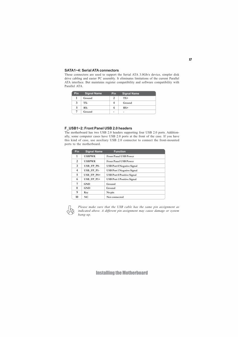
F_USB1~2: Front Panel USB 2.0 headersThe motherboard has two USB 2.0 headers supporting four USB 2.0 ports. Addition-ally, some computer cases have USB 2.0 ports at the front of the case. If you havethis kind of case, use auxiliary USB 2.0 connector to connect the front-mountedports to the motherboard.
Please make sure that the USB cable has the same pin assignment asindicated above. A different pin assignment may cause damage or systemhang-up.
1 USBPWR Front Panel USB Power
2 USBPWR Front Panel USB Power
3 USB_FP_P0- USB Port 0 Negative Signal
4 USB_FP_P1- USB Port 1 Negative Signal
5 USB_FP_P0+ USB Port 0 Positive Signal
6 USB_FP_P1+ USB Port 1 Positive Signal
7 GND Ground
8 GND Ground
9 Key No pin
10 NC Not connected
Pin Signal Name Function
SATA1~4: Serial ATA connectorsThese connectors are used to support the Serial ATA 3.0Gb/s device, simpler diskdrive cabling and easier PC assembly. It eliminates limitations of the current ParallelATA interface. But maintains register compatibility and software compatibility withParallel ATA.
1 Ground 2 TX+
3 TX- 4 Ground
5 RX- 6 RX+
7 Ground - -
Pin Signal NamePin Signal Name
18
Installing the Motherboard
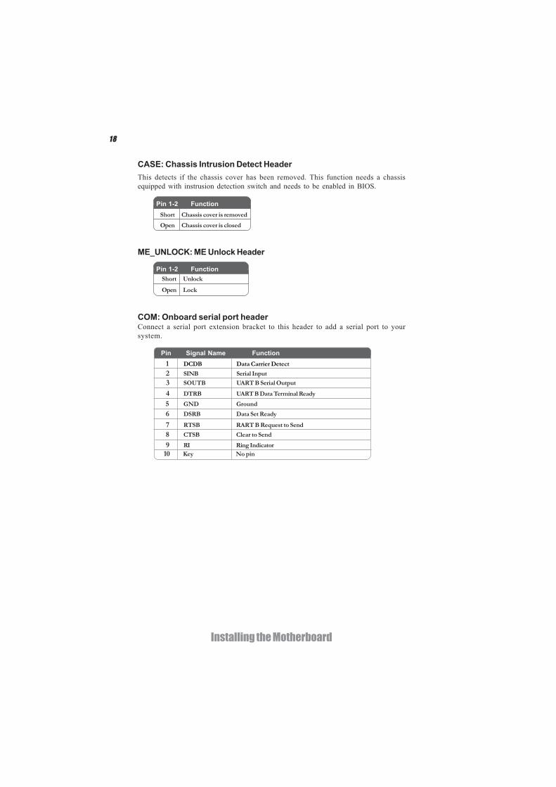
CASE: Chassis Intrusion Detect Header
Short Chassis cover is removed
Open Chassis cover is closed
This detects if the chassis cover has been removed. This function needs a chassisequipped with instrusion detection switch and needs to be enabled in BIOS.
Pin 1-2 Function
ME_UNLOCK: ME Unlock Header
Short Unlock
Open Lock
Pin 1-2 Function
COM: Onboard serial port headerConnect a serial port extension bracket to this header to add a serial port to yoursystem.
1 DCDB Data Carrier Detect
2 SINB Serial Input
3 SOUTB UART B Serial Output
4 DTRB UART B Data Terminal Ready
5 GND Ground
6 DSRB Data Set Ready
7 RTSB RART B Request to Send
8 CTSB Clear to Send
9 RI Ring Indicator10 Key No pin
Pin Signal Name Function
19
Installing the Motherboard
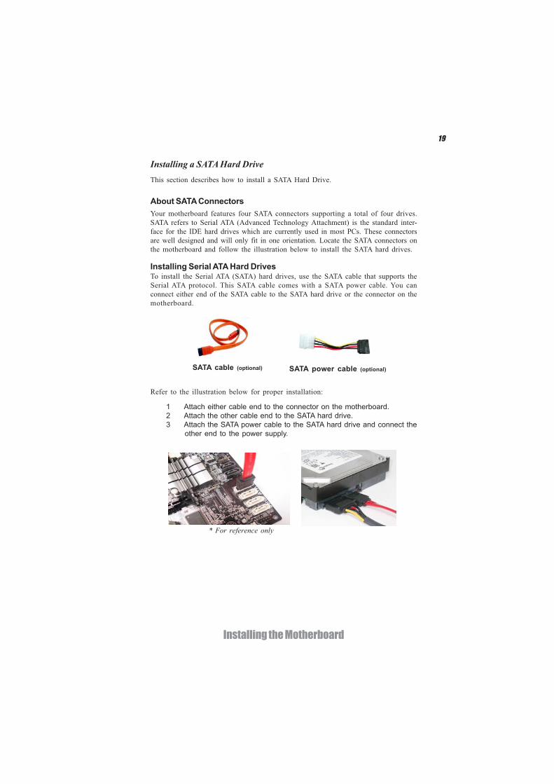
Installing a SATA Hard DriveThis section describes how to install a SATA Hard Drive.
SATA cable (optional) SATA power cable (optional)
About SATA ConnectorsYour motherboard features four SATA connectors supporting a total of four drives.SATA refers to Serial ATA (Advanced Technology Attachment) is the standard inter-face for the IDE hard drives which are currently used in most PCs. These connectorsare well designed and will only fit in one orientation. Locate the SATA connectors onthe motherboard and follow the illustration below to install the SATA hard drives.
Installing Serial ATA Hard DrivesTo install the Serial ATA (SATA) hard drives, use the SATA cable that supports theSerial ATA protocol. This SATA cable comes with a SATA power cable. You canconnect either end of the SATA cable to the SATA hard drive or the connector on themotherboard.
Refer to the illustration below for proper installation:
1 Attach either cable end to the connector on the motherboard.2 Attach the other cable end to the SATA hard drive.3 Attach the SATA power cable to the SATA hard drive and connect the
other end to the power supply.
* For reference only
20
Installing the Motherboard
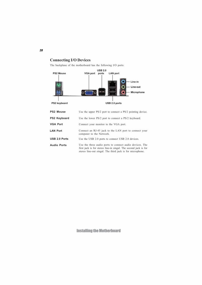
Connecting I/O DevicesThe backplane of the motherboard has the following I/O ports:
LAN Port Connect an RJ-45 jack to the LAN port to connect yourcomputer to the Network.
VGA Port Connect your monitor to the VGA port.
Audio Ports Use the three audio ports to connect audio devices. Thefirst jack is for stereo line-in singal. The second jack is forstereo line-out singal. The third jack is for microphone.
Use the USB 2.0 ports to connect USB 2.0 devices.USB 2.0 Ports
PS2 Keyboard Use the lower PS/2 port to connect a PS/2 keyboard.
PS2 Mouse Use the upper PS/2 port to connect a PS/2 pointing device.
21
Installing the Motherboard
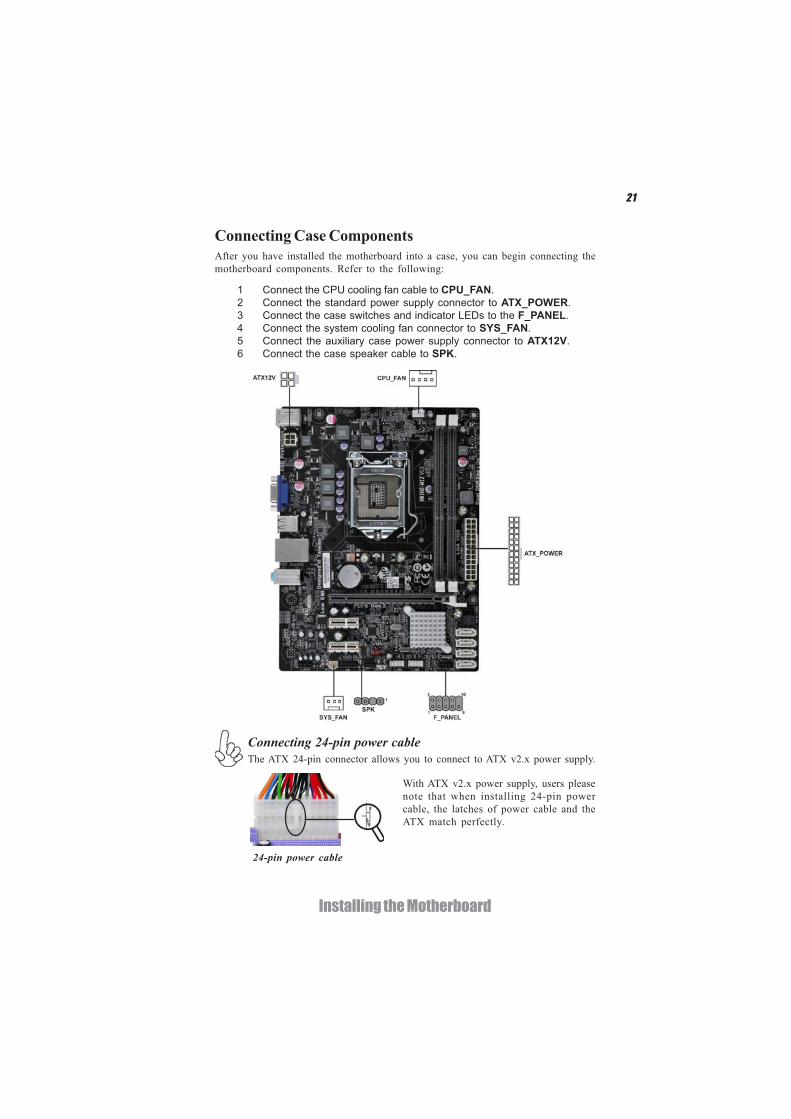
Connecting Case ComponentsAfter you have installed the motherboard into a case, you can begin connecting themotherboard components. Refer to the following:
The ATX 24-pin connector allows you to connect to ATX v2.x power supply.
With ATX v2.x power supply, users pleasenote that when installing 24-pin powercable, the latches of power cable and theATX match perfectly.
Connecting 24-pin power cable
24-pin power cable
1 Connect the CPU cooling fan cable to CPU_FAN.2 Connect the standard power supply connector to ATX_POWER.3 Connect the case switches and indicator LEDs to the F_PANEL.4 Connect the system cooling fan connector to SYS_FAN.5 Connect the auxiliary case power supply connector to ATX12V.6 Connect the case speaker cable to SPK.
22
Installing the Motherboard
ATX_POWER: ATX 24-pin Power Connector
Users please note that the fan connector supports the CPU cooling fan of1.1A ~ 2.2A (26.4W max) at +12V.
CPU_FAN: CPU cooling FAN Power Connector
1 GND System Ground
3 Sense Sensor4 PWM PWM
Pin Signal Name Function
2 +12V Power +12V
SYS_FAN: System Cooling FAN Power Connector
1 GND System Ground
3 Sense Sensor
Pin Signal Name Function
2 +12V Power +12V
Pin Signal Name Pin Signal Name1 +3.3V 13 +3.3V
2 +3.3V 14 -12V
3 Ground 15 Ground
4 +5V 16 PS_ON
5 Ground 17 Ground
6 +5V 18 Ground
7 Ground 19 Ground
8 PWRGD 20 -5V
9 +5VSB 21 +5V
10 +12V 22 +5V
11 +12V 23 +5V
12 +3.3V 24 Ground
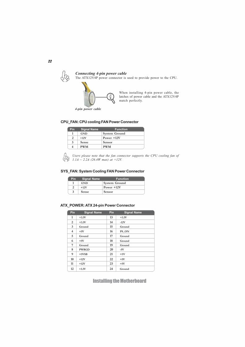
The ATX12V4P power connector is used to provide power to the CPU.
When installing 4-pin power cable, thelatches of power cable and the ATX12V4Pmatch perfectly.
Connecting 4-pin power cable
4-pin power cable
23
Installing the Motherboard
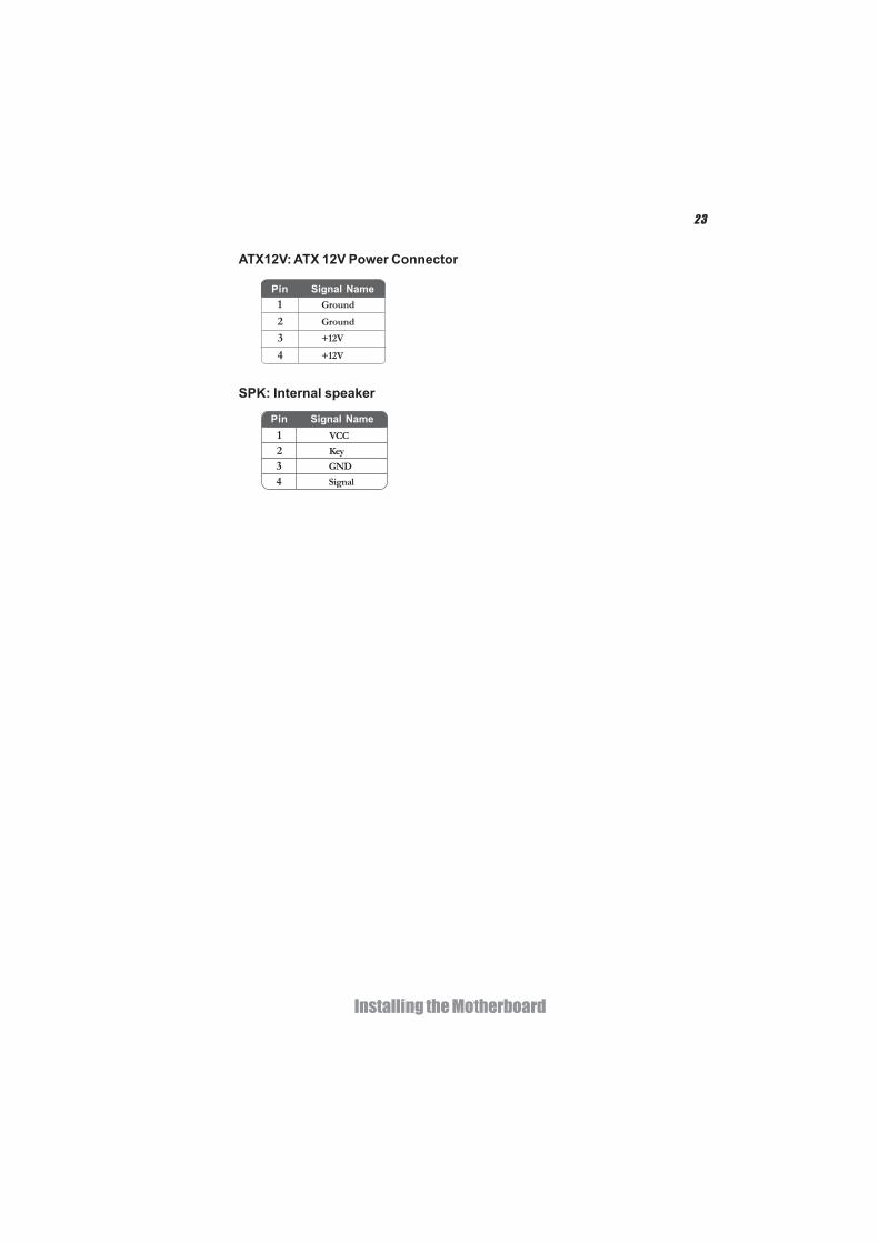
ATX12V: ATX 12V Power Connector
Pin Signal Name
4 +12V
3 +12V
2 Ground
1 Ground
SPK: Internal speaker
Pin Signal Name1 VCC
2 Key
3 GND
4 Signal
24
Installing the Motherboard
Hard Drive Activity LEDConnecting pins 1 and 3 to a front panel mounted LED provides visual indication thatdata is being read from or written to the hard drive. For the LED to function properly,an IDE drive should be connected to the onboard IDE interface. The LED will alsoshow activity for devices connected to the SCSI (hard drive activity LED) connector.
Power/Sleep/Message waiting LEDConnecting pins 2 and 4 to a single or dual-color, front panel mounted LED providespower on/off, sleep, and message waiting indication.
Reset SwitchSupporting the reset function requires connecting pin 5 and 7 to a momentary-contact switch that is normally open. When the switch is closed, the board resets andruns POST.
Power SwitchSupporting the power on/off function requires connecting pins 6 and 8 to a momen-tary-contact switch that is normally open. The switch should maintain contact for atleast 50 ms to signal the power supply to switch on or off. The time requirement isdue to internal de-bounce circuitry. After receiving a power on/off signal, at least twoseconds elapses before the power supply recognizes another on/off signal.
This concludes Chapter 2. The next chapter covers the BIOS.
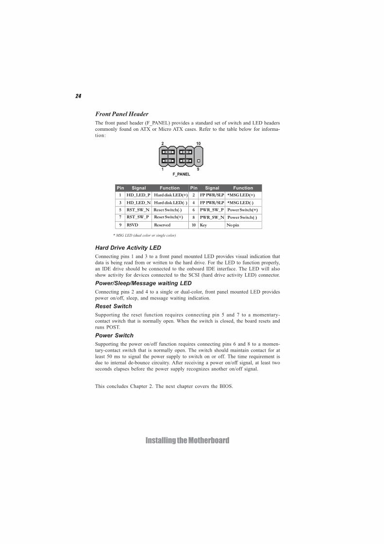
Front Panel HeaderThe front panel header (F_PANEL) provides a standard set of switch and LED headerscommonly found on ATX or Micro ATX cases. Refer to the table below for informa-tion:
Pin Signal Function Pin Signal Function1 HD_LED_P Hard disk LED(+) 2 FP PWR/SLP *MSG LED(+)
3 HD_LED_N Hard disk LED(- )
5 RST_SW_N Reset Switch(-)7 RST_SW_P Reset Switch(+)
9 RSVD Reserved
4 FP PWR/SLP *MSG LED(-)6 PWR_SW_P Power Switch(+)
8 PWR_SW_N Power Switch(-)
10 Key No pin
* MSG LED (dual color or single color)
25
Using BIOS
About the Setup UtilityThe computer uses the latest “American Megatrends Inc. ” BIOS with support forWindows Plug and Play. The CMOS chip on the motherboard contains the ROMsetup instructions for configuring the motherboard BIOS.
The BIOS (Basic Input and Output System) Setup Utility displays the system’sconfiguration status and provides you with options to set system parameters. Theparameters are stored in battery-backed-up CMOS RAM that saves this informationwhen the power is turned off. When the system is turned back on, the system isconfigured with the values you stored in CMOS.
The BIOS Setup Utility enables you to configure:
• Hard drives, diskette drives and peripherals• Video display type and display options• Password protection from unauthorized use• Power Management features
The settings made in the Setup Utility affect how the computer performs. Beforeusing the Setup Utility, ensure that you understand the Setup Utility options.
This chapter provides explanations for Setup Utility options.
The Standard ConfigurationA standard configuration has already been set in the Setup Utility. However, werecommend that you read this chapter in case you need to make any changes in thefuture.
This Setup Utility should be used:• when changing the system configuration• when a configuration error is detected and you are prompted to make
changes to the Setup Utility• when trying to resolve IRQ conflicts• when making changes to the Power Management configuration• when changing the password or making other changes to the Security
Setup
Entering the Setup UtilityWhen you power on the system, BIOS enters the Power-On Self Test (POST)routines. POST is a series of built-in diagnostics performed by the BIOS. After thePOST routines are completed, the following message appears:
Press DEL to enter SETUP
Chapter 3
Using BIOS

26
Using BIOS
Press the delete key to access BIOS Setup Utility.
Using BIOSWhen you start the Setup Utility, the main menu appears. The main menu of theSetup Utility displays a list of the options that are available. A highlight indicateswhich option is currently selected. Use the cursor arrow keys to move the highlightto other options. When an option is highlighted, execute the option by pressing<Enter>.
Some options lead to pop-up dialog boxes that prompt you to verify that you wish toexecute that option. Other options lead to dialog boxes that prompt you for infor-mation.
Some options (marked with a icon ) lead to submenus that enable you to change thevalues for the option. Use the cursor arrow keys to scroll through the items in thesubmenu.
Resetting the Default CMOS ValuesWhen powering on for the first time, the POST screen may show a “CMOSSettings Wrong” message. This standard message will appear following a clearCMOS data at factory by the manufacturer. You simply need to Load DefaultSettings to reset the default CMOS values.
Note: Changes to system hardware such as different CPU, memories, etc. may alsotrigger this message.
27
Using BIOS
The default BIOS setting for this motherboard apply for most conditionswith optimum performance. We do not suggest users change the defaultvalues in the BIOS setup and take no responsibility to any damagecaused by changing the BIOS settings.
BIOS Navigation KeysThe BIOS navigation keys are listed below:
KEY FUNCTION
Scrolls through the items on a menu
+/- Change Opt.
F2 Previous Value
F3 Optimized Defaults
F1 General Help
ESC Exits the current menu
Enter Select
In this manual, default values are enclosed in parenthesis. Submenu items are denotedby a icon .
F4 Save & Exit
1. For the purpose of better product maintenance, the manufacturereserves the right to change the BIOS items presented in this manual.The BIOS setup screens shown in this chapter are for reference only andmay differ from the actual BIOS. Please visit the manufacture’s websitefor updated manual.
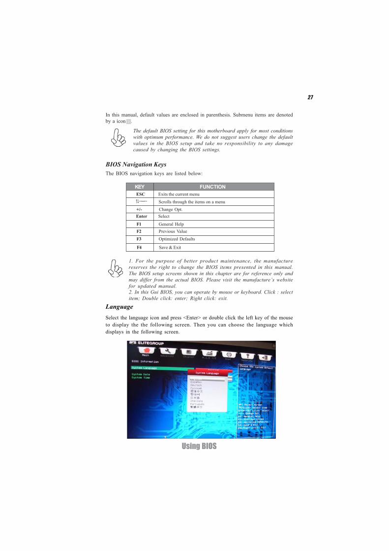
Select the language icon and press <Enter> or double click the left key of the mouseto display the the following screen. Then you can choose the language whichdisplays in the following screen.
Language
2. In this Gui BIOS, you can operate by mouse or keyboard. Click : selectitem; Double click: enter; Right click: exit.
28
Using BIOS
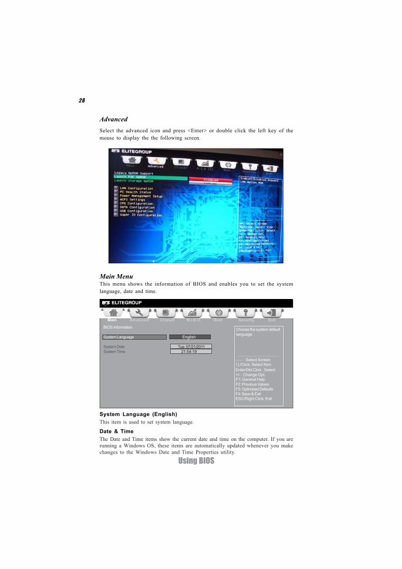
Main Menu
Select the advanced icon and press <Enter> or double click the left key of themouse to display the the following screen.
Advanced
Date & TimeThe Date and Time items show the current date and time on the computer. If you arerunning a Windows OS, these items are automatically updated whenever you makechanges to the Windows Date and Time Properties utility.
System Language (English)This item is used to set system language.
This menu shows the information of BIOS and enables you to set the systemlanguage, date and time.
Choose the system defaultlanguage
Main Advanced Chipset M.I.B III Boot Security Exit
+/- : Change Opt.Enter/Dbl Click : Select
: Select Screen/Click: Select Item
F1: General HelpF2: Previous ValuesF3: Optimized DefaultsF4: Save & ExitESC/Right Click: Exit
BIOS Information
System Language English
System Date Tue 07/21/2011System Time 21:54:19
29
Using BIOS
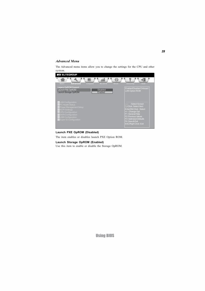
The Advanced menu items allow you to change the settings for the CPU and othersystem.
Advanced Menu
Launch PXE OpROM (Disabled)The item enables or disables launch PXE Option ROM.
Enabled/Disabled OnboardLAN Option ROM
Main Advanced Chipset M.I.B III Boot Security Exit
+/- : Change Opt.Enter/Dbl Click : Select
: Select Screen/Click: Select Item
F1: General HelpF2: Previous ValuesF3: Optimized DefaultsF4: Save & ExitESC/Right Click: Exit
Launch Storage OpROM (Enabled)Use this item to enable or disable the Storage OpROM.
Legacy OpROM SupportLaunch PXE OpROM DisabledLaunch Storage OpROM Enabled
LAN Configuration PC Health Status Power Management Setup ACPI Settings CPU Configuration SATA Configuration USB Configuration
Super IO Configuration
30
Using BIOS
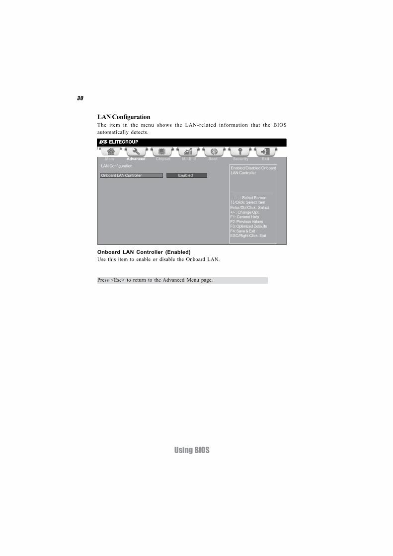
Onboard LAN Controller (Enabled)Use this item to enable or disable the Onboard LAN.
LAN ConfigurationThe item in the menu shows the LAN-related information that the BIOSautomatically detects.
Press <Esc> to return to the Advanced Menu page.
Enabled/Disabled OnboardLAN Controller
Main Advanced Chipset M.I.B III Boot Security Exit
+/- : Change Opt.Enter/Dbl Click : Select
: Select Screen/Click: Select Item
F1: General HelpF2: Previous ValuesF3: Optimized DefaultsF4: Save & ExitESC/Right Click: Exit
LAN Configuration
Onboard LAN Controller Enabled
31
Using BIOS
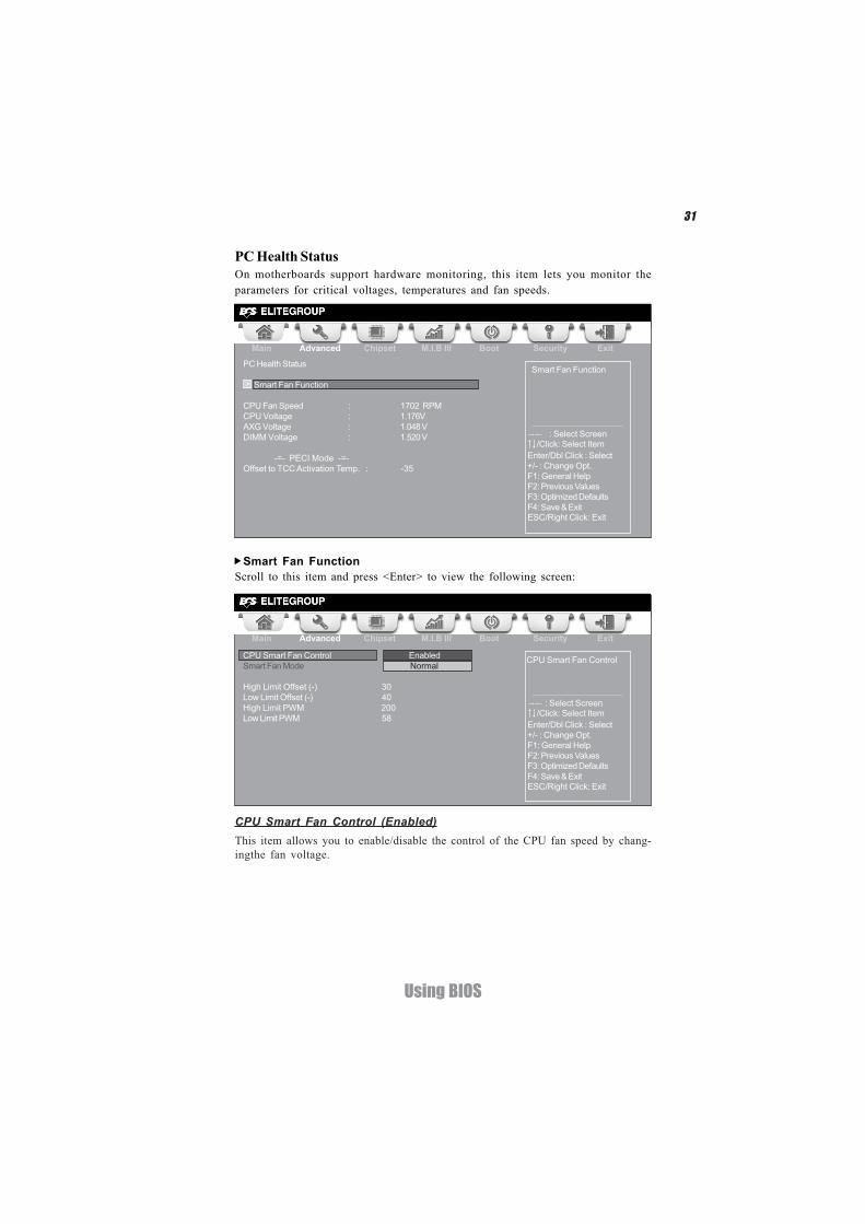
PC Health StatusOn motherboards support hardware monitoring, this item lets you monitor theparameters for critical voltages, temperatures and fan speeds.
Scroll to this item and press <Enter> to view the following screen:Smart Fan Function
CPU Smart Fan Control (Enabled)
Main Advanced Chipset M.I.B III Boot Security Exit
+/- : Change Opt.Enter/Dbl Click : Select
: Select Screen/Click: Select Item
F1: General HelpF2: Previous ValuesF3: Optimized DefaultsF4: Save & ExitESC/Right Click: Exit
Main Advanced Chipset M.I.B III Boot Security Exit
CPU Smart Fan Control EnabledSmart Fan Mode Normal
High Limit Offset (-) 30Low Limit Offset (-) 40High Limit PWM 200Low Limit PWM 58
PC Health Status
Smart Fan Function
CPU Fan Speed : 1702 RPMCPU Voltage : 1.176VAXG Voltage : 1.048 VDIMM Voltage : 1.520 V
-=- PECI Mode -=-Offset to TCC Activation Temp. : -35
Smart Fan Function
CPU Smart Fan Control
+/- : Change Opt.Enter/Dbl Click : Select
: Select Screen/Click: Select Item
F1: General HelpF2: Previous ValuesF3: Optimized DefaultsF4: Save & ExitESC/Right Click: Exit
This item allows you to enable/disable the control of the CPU fan speed by chang-ingthe fan voltage.
32
Using BIOS
• CPU Fan Speed • CPU Voltage • AXG Voltage • DIMM Voltage
System Component CharacteristicsThese items display the monitoring of the overall inboard hardware health events,such as System & CPU temperature, CPU & DIMM voltage, CPU & system fanspeed,... etc.
Press <Esc> to return to the Advanced Menu page.
Smart Fan Mode (Normal)This item allows you to select the fan mode (Normal, Quiet, Silent, or Manual) for abetter operation environment. If you choose Normal mode, the fan speed will be autoadjusted depending on the CPU temperature. If you choose Quite mode, the fan speedwill be auto minimized for quiet environment. If you choose Silent mode, the fanspeed will be auto restricted to make system more quietly. If you choose Manualmode, the fan speed will be adjust depending on users’ parameters.
Press <Esc> to return to the PC Health Status page.
33
Using BIOS
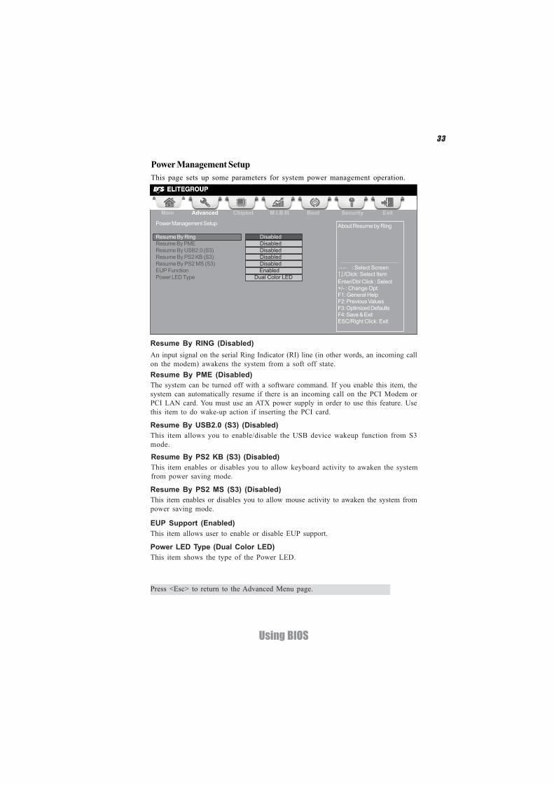
Power Management SetupThis page sets up some parameters for system power management operation.
Resume By PME (Disabled)The system can be turned off with a software command. If you enable this item, thesystem can automatically resume if there is an incoming call on the PCI Modem orPCI LAN card. You must use an ATX power supply in order to use this feature. Usethis item to do wake-up action if inserting the PCI card.
Resume By USB2.0 (S3) (Disabled)This item allows you to enable/disable the USB device wakeup function from S3mode.
EUP Support (Enabled)This item allows user to enable or disable EUP support.
Press <Esc> to return to the Advanced Menu page.
Resume By RING (Disabled)An input signal on the serial Ring Indicator (RI) line (in other words, an incoming callon the modem) awakens the system from a soft off state.
Power LED Type (Dual Color LED)This item shows the type of the Power LED.
Resume By PS2 MS (S3) (Disabled)This item enables or disables you to allow mouse activity to awaken the system frompower saving mode.
Resume By PS2 KB (S3) (Disabled)This item enables or disables you to allow keyboard activity to awaken the systemfrom power saving mode.
Main Advanced Chipset M.I.B III Boot Security Exit
+/- : Change Opt.Enter/Dbl Click : Select
: Select Screen/Click: Select Item
F1: General HelpF2: Previous ValuesF3: Optimized DefaultsF4: Save & ExitESC/Right Click: Exit
Power Management Setup
Resume By Ring DisabledResume By PME DisabledResume By USB2.0 (S3) DisabledResume By PS2 KB (S3) DisabledResume By PS2 MS (S3) DisabledEUP Function EnabledPower LED Type Dual Color LED
About Resume by Ring
34
Using BIOS
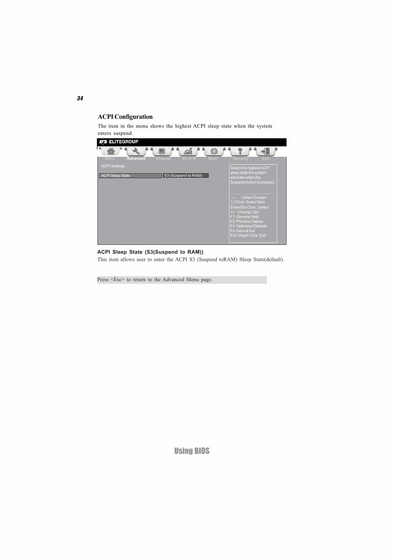
ACPI ConfigurationThe item in the menu shows the highest ACPI sleep state when the systementers suspend.
ACPI Sleep State (S3(Suspend to RAM))This item allows user to enter the ACPI S3 (Suspend toRAM) Sleep State(default).
Press <Esc> to return to the Advanced Menu page.
Aptio Setup Utility - Copyright (C) 2011 American Megatrends, Inc.
Main Advanced Chipset M.I.B III Boot Security Exit
+/- : Change Opt.Enter/Dbl Click : Select
: Select Screen/Click: Select Item
F1: General HelpF2: Previous ValuesF3: Optimized DefaultsF4: Save & ExitESC/Right Click: Exit
ACPI Settings
ACPI Sleep State S3 (Suspend to RAM)
Select the highest ACPIsleep state the systemwill enter when theSuspend button is pressed.
35
Using BIOS
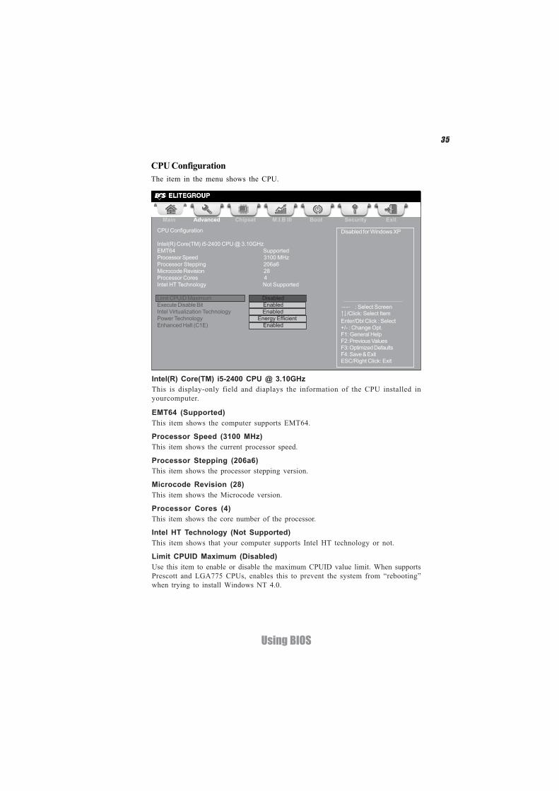
CPU ConfigurationThe item in the menu shows the CPU.
Intel(R) Core(TM) i5-2400 CPU @ 3.10GHzThis is display-only field and diaplays the information of the CPU installed inyourcomputer.
EMT64 (Supported)This item shows the computer supports EMT64.
Microcode Revision (28)This item shows the Microcode version.
Processor Stepping (206a6)This item shows the processor stepping version.
Intel HT Technology (Not Supported)This item shows that your computer supports Intel HT technology or not.
Processor Cores (4)This item shows the core number of the processor.
Limit CPUID Maximum (Disabled)Use this item to enable or disable the maximum CPUID value limit. When supportsPrescott and LGA775 CPUs, enables this to prevent the system from “rebooting”when trying to install Windows NT 4.0.
Main Advanced Chipset M.I.B III Boot Security Exit
Disabled for Windows XPCPU Configuration
Intel(R) Core(TM) i5-2400 CPU @ 3.10GHzEMT64 SupportedProcessor Speed 3100 MHzProcessor Stepping 206a6Microcode Revision 28Processor Cores 4Intel HT Technology Not Supported
Limit CPUID Maximum DisabledExecute Disable Bit EnabledIntel Virtualization Technology EnabledPower Technology Energy EfficientEnhanced Halt (C1E) Enabled +/- : Change Opt.
Enter/Dbl Click : Select
: Select Screen/Click: Select Item
F1: General HelpF2: Previous ValuesF3: Optimized DefaultsF4: Save & ExitESC/Right Click: Exit
Processor Speed (3100 MHz)This item shows the current processor speed.
36
Using BIOS
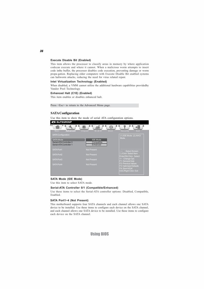
SATA ConfigurationUse this item to show the mode of serial ATA configuration options.
Serial-ATA Controller 0/1 (Compatible/Enhanced)Use these items to select the Serial-ATA controller options: Disabled, Compatible,Enabled.
SATA Port1~4 (Not Present)This motherboard supports four SATA channels and each channel allows one SATAdevice to be installed. Use these items to configure each device on the SATA channel,and each channel allows one SATA device to be installed. Use these items to configureeach device on the SATA channel.
SATA Mode (IDE Mode)Use this item to select SATA mode.
Execute Disable Bit (Enabled)This item allows the processor to classify areas in memory by where applicationcodecan execute and where it cannot. When a malicious worm attempts to insertcode inthe buffer, the processor disables code execution, preventing damage or wormpropa-gation. Replacing older computers with Execute Disable Bit enabled systemscan haltworm attacks, reducing the need for virus related repair.Intel Virtualization Technology (Enabled)When disabled, a VMM cannot utilize the additional hardware capabilities providedbyVandor Pool Technology.Enhanced Halt (C1E) (Enabled)This item enables or disables enhanced halt.
Press <Esc> to return to the Advanced Menu page.
Main Advanced Chipset M.I.B III Boot Security Exit
+/- : Change Opt.Enter/Dbl Click : Select
: Select Screen/Click: Select Item
F1: General HelpF2: Previous ValuesF3: Optimized DefaultsF4: Save & ExitESC/Right Click: Exit
SATA Configuration
SATA Mode IDE ModeSerial-ATA Controller 0 CompatibleSerial-ATA Controller 1 Enhanced
SATA Port1 Not Present
SATA Port2 Not Present
SATA Port3 Not Present
SATA Port4 Not Present
(1) IDE Mode. (2) AHCIMode.
37
Using BIOS
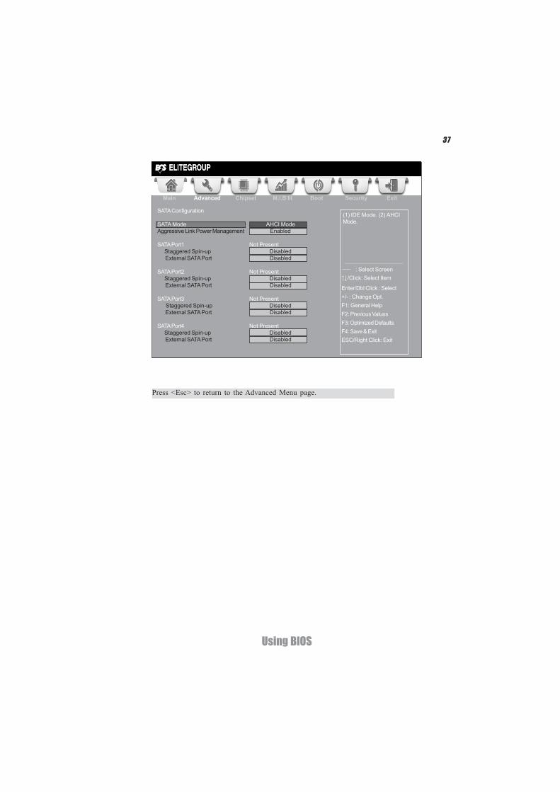
Press <Esc> to return to the Advanced Menu page.
Main Advanced Chipset M.I.B III Boot Security Exit
+/- : Change Opt.Enter/Dbl Click : Select
: Select Screen/Click: Select Item
F1: General HelpF2: Previous ValuesF3: Optimized DefaultsF4: Save & ExitESC/Right Click: Exit
(1) IDE Mode. (2) AHCIMode.
SATA Configuration
SATA Mode AHCI ModeAggressive Link Power Management Enabled
SATA Port1 Not Present Staggered Spin-up Disabled External SATA Port Disabled
SATA Port2 Not Present Staggered Spin-up Disabled External SATA Port Disabled
SATA Port3 Not Present Staggered Spin-up Disabled
External SATA Port Disabled
SATA Port4 Not PresentStaggered Spin-up Disabled
External SATA Port Disabled
38
Using BIOS
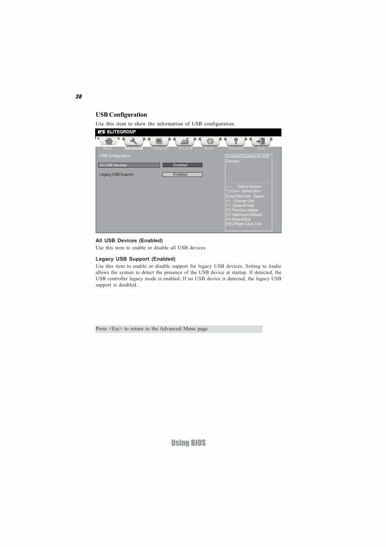
All USB Devices (Enabled)Use this item to enable or disable all USB devices.
USB ConfigurationUse this item to show the information of USB configuration.
Main Advanced Chipset M.I.B III Boot Security Exit
+/- : Change Opt.Enter/Dbl Click : Select
: Select Screen/Click: Select Item
F1: General HelpF2: Previous ValuesF3: Optimized DefaultsF4: Save & ExitESC/Right Click: Exit
USB Configuration
All USB Devices Enabled
Legacy USB Support Enabled
Enabled/Disabled All USBDevices
Press <Esc> to return to the Advanced Menu page.
Legacy USB Support (Enabled)Use this item to enable or disable support for legacy USB devices. Setting to Audioallows the system to detect the presence of the USB device at startup. If detected, theUSB controller legacy mode is enabled. If no USB device is detected, the legacy USBsupport is disabled.
39
Using BIOS
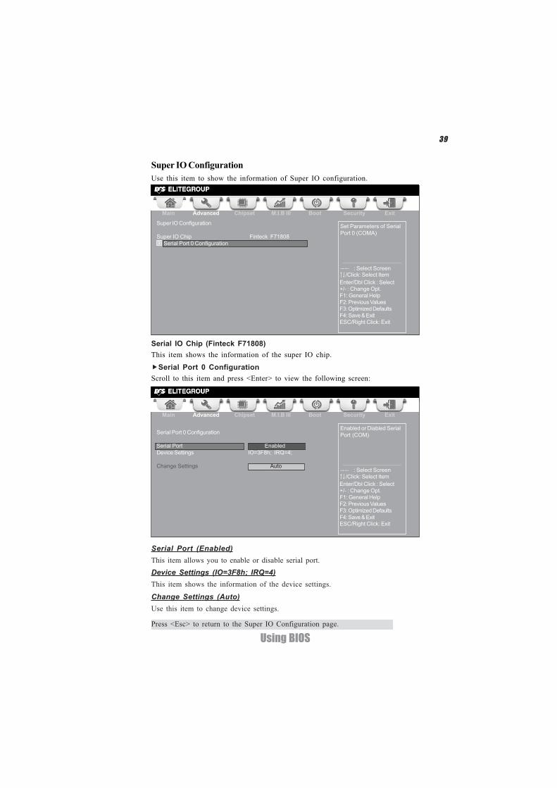
Serial Port 0 ConfigurationScroll to this item and press <Enter> to view the following screen:
Serial Port (Enabled)This item allows you to enable or disable serial port.Device Settings (IO=3F8h; IRQ=4)This item shows the information of the device settings.
Change Settings (Auto)Use this item to change device settings.
Press <Esc> to return to the Super IO Configuration page.
Main Advanced Chipset M.I.B III Boot Security Exit
+/- : Change Opt.Enter/Dbl Click : Select
: Select Screen/Click: Select Item
F1: General HelpF2: Previous ValuesF3: Optimized DefaultsF4: Save & ExitESC/Right Click: Exit
Serial Port 0 Configuration
Serial Port EnabledDevice Settings IO=3F8h; IRQ=4;
Change Settings Auto
Enabled or Diabled SerialPort (COM)
Super IO ConfigurationUse this item to show the information of Super IO configuration.
Set Parameters of SerialPort 0 (COMA)
Main Advanced Chipset M.I.B III Boot Security Exit
+/- : Change Opt.Enter/Dbl Click : Select
: Select Screen/Click: Select Item
F1: General HelpF2: Previous ValuesF3: Optimized DefaultsF4: Save & ExitESC/Right Click: Exit
Super IO Configuration
Super IO Chip Finteck F71808 Serial Port 0 Configuration
Serial IO Chip (Finteck F71808)This item shows the information of the super IO chip.
40
Using BIOS
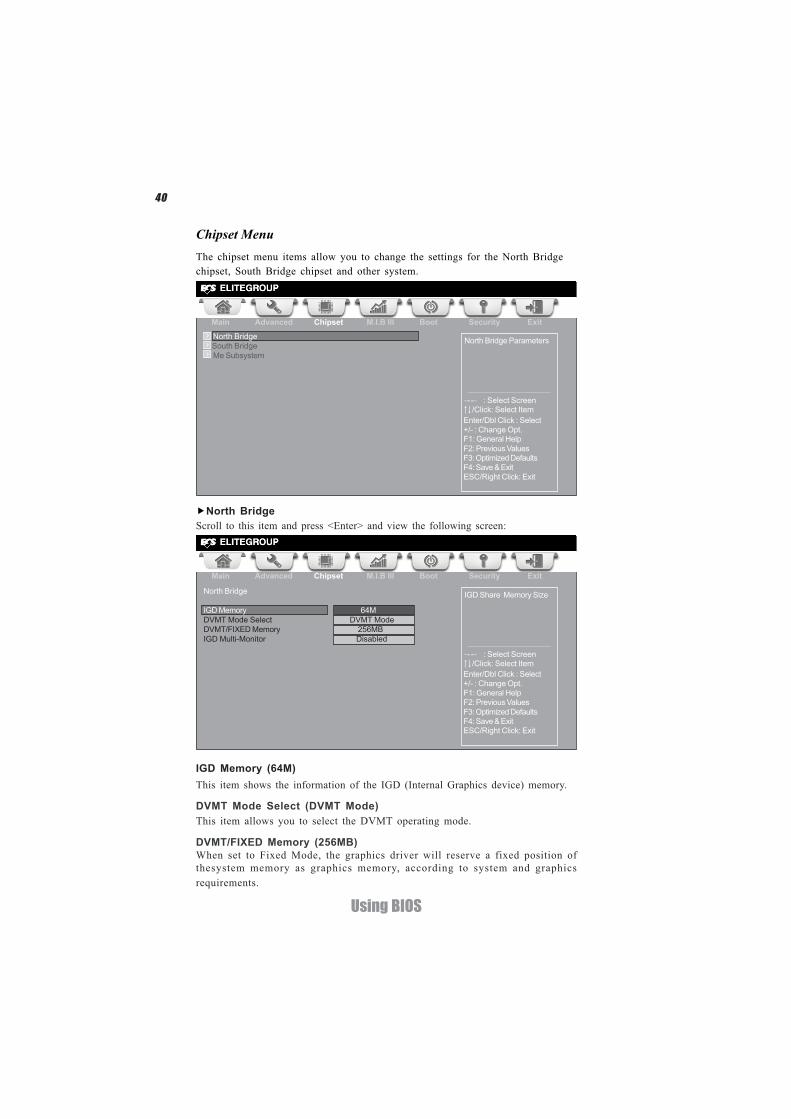
North BridgeScroll to this item and press <Enter> and view the following screen:
IGD Memory (64M)This item shows the information of the IGD (Internal Graphics device) memory.
The chipset menu items allow you to change the settings for the North Bridgechipset, South Bridge chipset and other system.
Chipset Menu
North Bridge Parameters
Main Advanced Chipset M.I.B III Boot Security Exit
+/- : Change Opt.Enter/Dbl Click : Select
: Select Screen/Click: Select Item
F1: General HelpF2: Previous ValuesF3: Optimized DefaultsF4: Save & ExitESC/Right Click: Exit
North BridgeSouth Bridge
Me Subsystem
DVMT Mode Select (DVMT Mode)This item allows you to select the DVMT operating mode.
Main Advanced Chipset M.I.B III Boot Security Exit
+/- : Change Opt.Enter/Dbl Click : Select
: Select Screen/Click: Select Item
F1: General HelpF2: Previous ValuesF3: Optimized DefaultsF4: Save & ExitESC/Right Click: Exit
IGD Share Memory SizeNorth Bridge
IGD Memory 64MDVMT Mode Select DVMT ModeDVMT/FIXED Memory 256MBIGD Multi-Monitor Disabled
DVMT/FIXED Memory (256MB)When set to Fixed Mode, the graphics driver will reserve a fixed position ofthesystem memory as graphics memory, according to system and graphicsrequirements.
41
Using BIOS
IGD Multi-Monitor (Enabled)This item enables or disables IGD(Internal Graphics device) multi-monitor.
Multi-Monitor technology
Please note that Multi-Monitor technology supports up to three monitors:one Intel integrated Graphics and one or two PCI-Express graphics de-vices under Windows 7.
Multi-Monitor technology can help you to increase the area available for programsrunning on a single computer system through using multiple display devices.It is not only to increase larger screen viewing but aslo to improving personalproductivity.
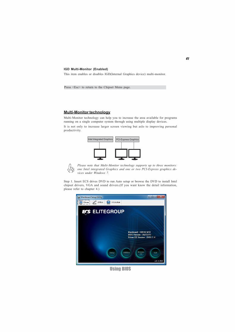
Step 1. Insert ECS drives DVD to run Auto setup or browse the DVD to install Intelchipset drivers, VGA and sound drivers.(If you want know the detail information,please refer to chapter 4.)
Intel Integrated Graphics PCI-Express Graphics
Press <Esc> to return to the Chipset Menu page.
42
Using BIOS
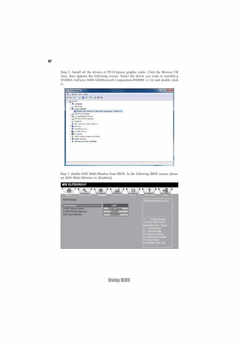
Step 3. Enable IGD Multi-Monitor from BIOS. In the following BIOS screen, pleaseset IGD Multi-Monitor to [Enabled].
Step 2. Install all the drivers of PCI-Express graphic cards. Click the Browse CDitem, then appears the following screen. Select the driver you want to install(e.gNVIDIA GeForce 8400 GS(Microsoft Corporation-WDDM v1.1)) and double clickit.
Main Advanced Chipset M.I.B III Boot Security Exit
+/- : Change Opt.Enter/Dbl Click : Select
: Select Screen/Click: Select Item
F1: General HelpF2: Previous ValuesF3: Optimized DefaultsF4: Save & ExitESC/Right Click: Exit
IGD Share Memory SizeNorth Bridge
IGD Memory 64MDVMT Mode Select DVMT ModeDVMT/FIXED Memory 256MBIGD Multi-Monitor Disabled
43
Using BIOS
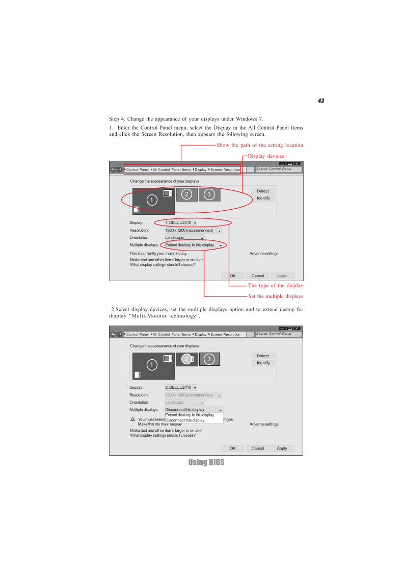
2.Select display devices, set the multiple displays option and to extend destop fordisplay “Multi-Monitor technology”.
Change the apprearance of your displays
Control Panel All Control Panel Items Display Screen Resolution Search Control Panel
13 Detect
Identify
2. DELL U2410Display:
Resolution: 1920 x 1200 (recommended)
Orientation: Landscape
Disconnect this displayMultiple displays:
Make this my main display Advance settingsMake text and other items larger or smallerWhat display settings should I choose?
OK Cancel Apply
2
You must select Apply before making additional changes.!Extend desktop to this displayDisconnect this display
Step 4. Change the appearance of your displays under Windows 7.
Change the apprearance of your displays
Control Panel All Control Panel Items Display Screen Resolution Search Control Panel
12 3 Detect
Identify
1. DELL U2410Display:
Resolution: 1920 x 1200 (recommended)
Orientation: Landscape
Extend desktop to this displayMultiple displays:
This is currently your main display. Advance settingsMake text and other items larger or smallerWhat display settings should I choose?
OK Cancel Apply
Show the path of the setting location
Display devices
The type of the display
Set the multiple displays
1. Enter the Control Panel menu, select the Display in the All Control Panel Itemsand click the Screen Resolution, then appears the following screen.
44
Using BIOS
Change the apprearance of your displays
Control Panel All Control Panel Items Display Screen Resolution Search Control Panel
1 Detect
Identify
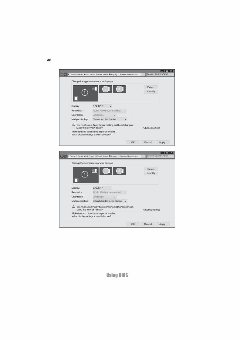
3. AL1717Display:
Resolution: 1920 x 1200 (recommended)
Orientation: Landscape
Disconnect this displayMultiple displays:
Make this my main display Advance settingsMake text and other items larger or smallerWhat display settings should I choose?
OK Cancel Apply
2
You must select Apply before making additional changes.!
3
3
Change the apprearance of your displays
Control Panel All Control Panel Items Display Screen Resolution Search Control Panel
1 Detect
Identify
3. AL1717Display:
Resolution: 1920 x 1200 (recommended)
Orientation: Landscape
Extend desktop to this displayMultiple displays:
Make this my main display Advance settingsMake text and other items larger or smallerWhat display settings should I choose?
OK Cancel Apply
2
You must select Apply before making additional changes.!
3
45
Using BIOS
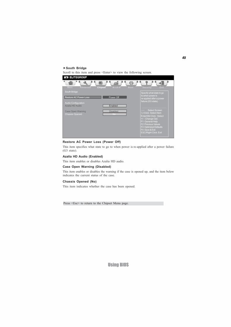
Case Open Warning (Disabled)This item enables or disables the warning if the case is opened up, and the item belowindicates the current status of the case.
Chassis Opened (No)This item indicates whether the case has been opened.
Press <Esc> to return to the Chipset Menu page.
South BridgeScroll to this item and press <Enter> to view the following screen.
Restore AC Power Loss (Power Off)This item specifies what state to go to when power is re-applied after a power failure(G3 state).
Azalia HD Audio (Enabled)This item enables or disables Azalia HD audio.
Main Advanced Chipset M.I.B III Boot Security Exit
+/- : Change Opt.Enter/Dbl Click : Select
: Select Screen/Click: Select Item
F1: General HelpF2: Previous ValuesF3: Optimized DefaultsF4: Save & ExitESC/Right Click: Exit
Specify what state to goto when power isre-applied after a powerfailure (G3 state).
South Bridge
Restore AC Power Loss Power Off
Audio ConfigurationAzalia HD Audio Enabled
Case Open Warning DisabledChassis Opened No
46
Using BIOS
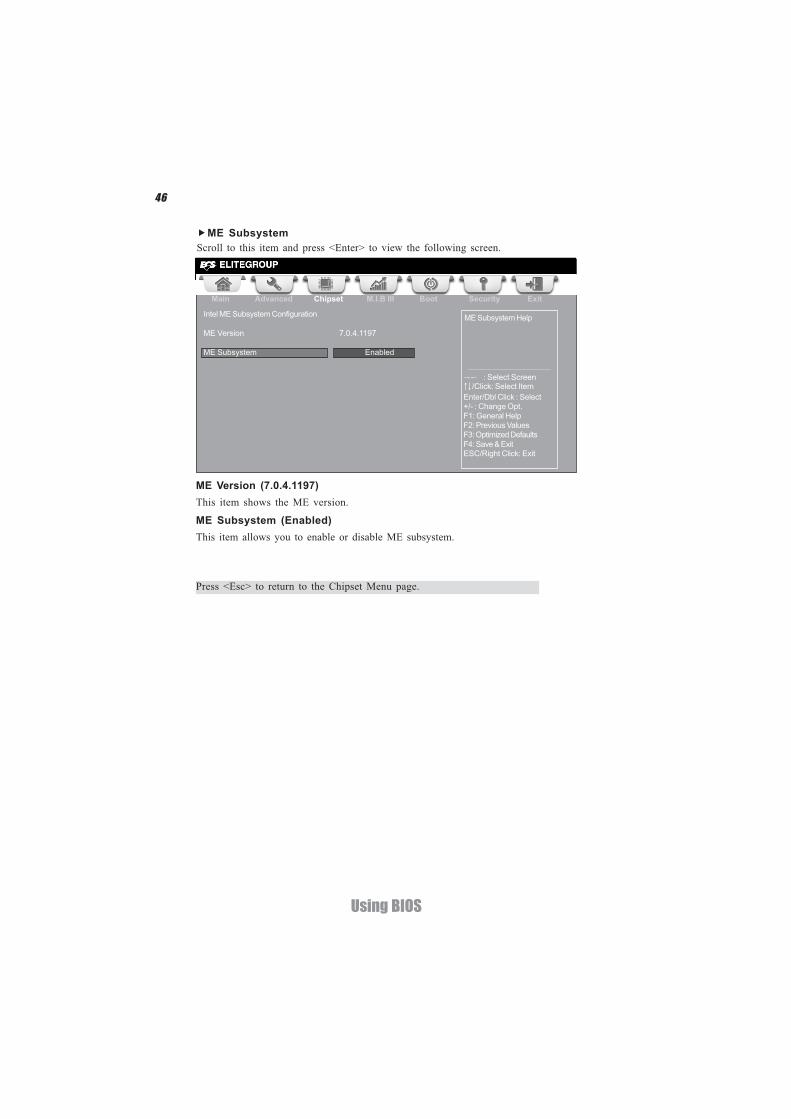
ME SubsystemScroll to this item and press <Enter> to view the following screen.
ME Version (7.0.4.1197)This item shows the ME version.
ME Subsystem (Enabled)This item allows you to enable or disable ME subsystem.
Main Advanced Chipset M.I.B III Boot Security Exit
+/- : Change Opt.Enter/Dbl Click : Select
: Select Screen/Click: Select Item
F1: General HelpF2: Previous ValuesF3: Optimized DefaultsF4: Save & ExitESC/Right Click: Exit
ME Subsystem HelpIntel ME Subsystem Configuration
ME Version 7.0.4.1197
ME Subsystem Enabled
Press <Esc> to return to the Chipset Menu page.
47
Using BIOS
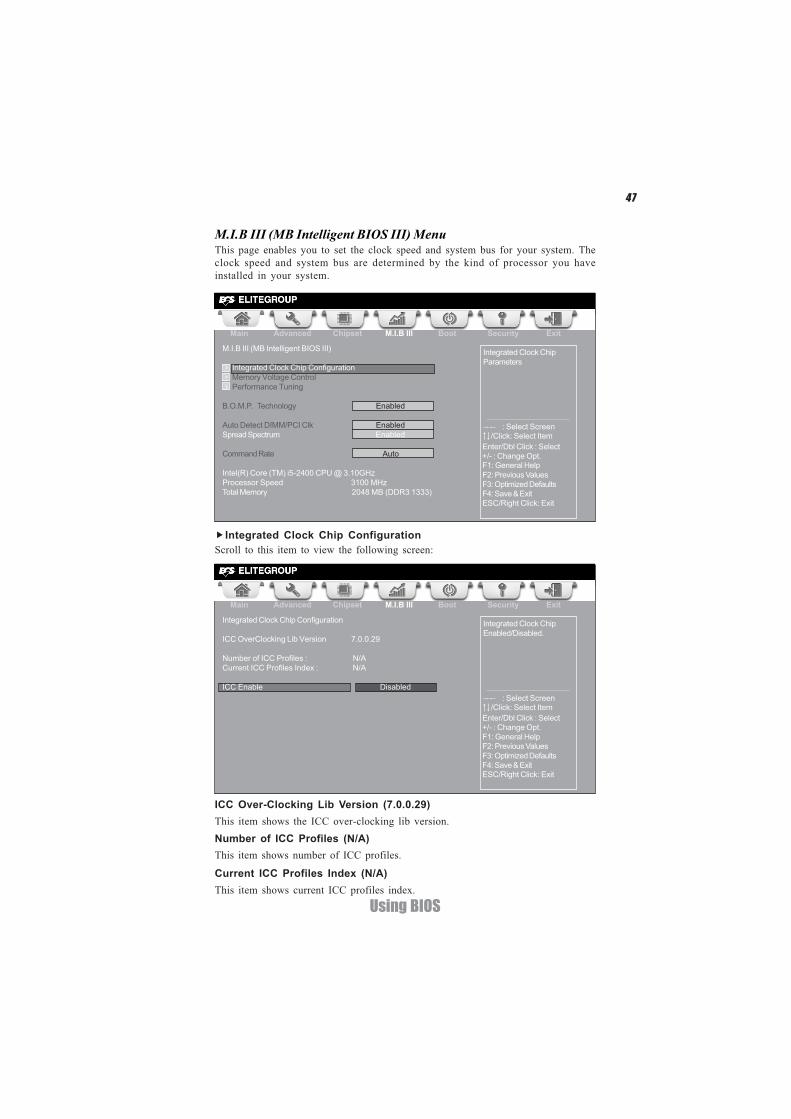
This page enables you to set the clock speed and system bus for your system. Theclock speed and system bus are determined by the kind of processor you haveinstalled in your system.
M.I.B III (MB Intelligent BIOS III) Menu
Integrated Clock Chip ConfigurationScroll to this item to view the following screen:
Main Advanced Chipset M.I.B III Boot Security Exit
+/- : Change Opt.Enter/Dbl Click : Select
: Select Screen/Click: Select Item
F1: General HelpF2: Previous Values
Integrated Clock ChipParameters
F3: Optimized DefaultsF4: Save & ExitESC/Right Click: Exit
M.I.B III (MB Intelligent BIOS III)
Integrated Clock Chip Configuration Memory Voltage Control Performance Tuning
B.O.M.P. Technology Enabled
Auto Detect DIMM/PCI Clk EnabledSpread Spectrum Enabled
Command Rate Auto
Intel(R) Core (TM) i5-2400 CPU @ 3.10GHzProcessor Speed 3100 MHzTotal Memory 2048 MB (DDR3 1333)
Main Advanced Chipset M.I.B III Boot Security Exit
+/- : Change Opt.Enter/Dbl Click : Select
: Select Screen/Click: Select Item
F1: General HelpF2: Previous Values
Integrated Clock ChipEnabled/Disabled.
F3: Optimized DefaultsF4: Save & ExitESC/Right Click: Exit
Integrated Clock Chip Configuration
ICC OverClocking Lib Version 7.0.0.29
Number of ICC Profiles : N/ACurrent ICC Profiles Index : N/A
ICC Enable Disabled
ICC Over-Clocking Lib Version (7.0.0.29)This item shows the ICC over-clocking lib version.Number of ICC Profiles (N/A)This item shows number of ICC profiles.
Current ICC Profiles Index (N/A)This item shows current ICC profiles index.
48
Using BIOS
ICC Enable (Disabled)This item allows you to enable or disable current ICC.
Press <Esc> to return to the M.I.B III Menu page.
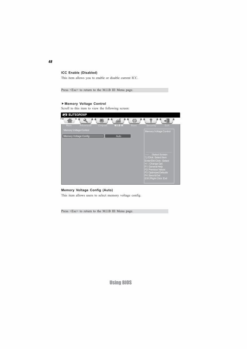
Memory Voltage ControlScroll to this item to view the following screen:
Main Advanced Chipset M.I.B III Boot Security Exit
+/- : Change Opt.Enter/Dbl Click : Select
: Select Screen/Click: Select Item
F1: General HelpF2: Previous Values
Memory Voltage Control
F3: Optimized DefaultsF4: Save & ExitESC/Right Click: Exit
Memory Voltage Control
Memory Voltage Config Auto
Memory Voltage Config (Auto)This item allows users to select memory voltage config.
Press <Esc> to return to the M.I.B III Menu page.
49
Using BIOS
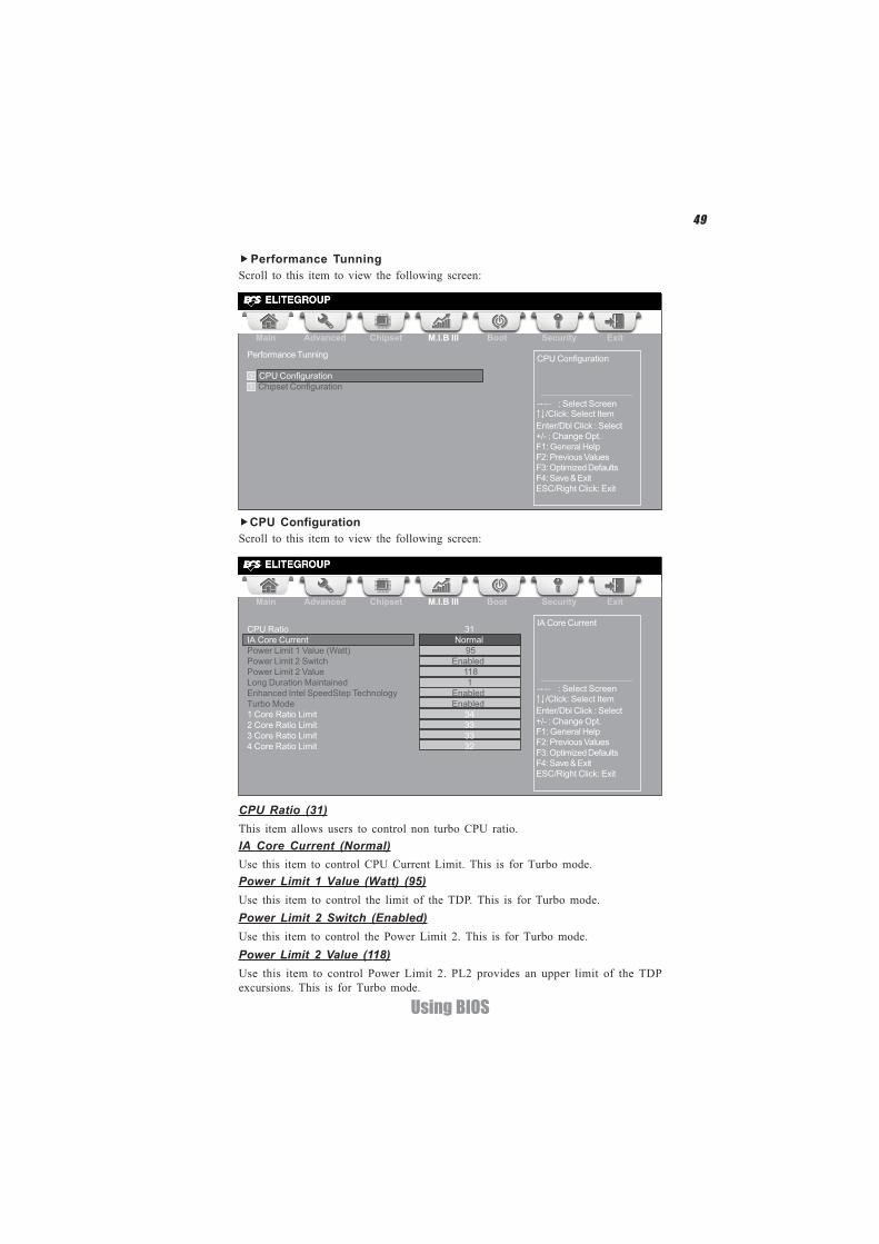
Performance TunningScroll to this item to view the following screen:
Main Advanced Chipset M.I.B III Boot Security Exit
+/- : Change Opt.Enter/Dbl Click : Select
: Select Screen/Click: Select Item
F1: General HelpF2: Previous Values
CPU Configuration
F3: Optimized DefaultsF4: Save & ExitESC/Right Click: Exit
Performance Tunning
CPU Configuration Chipset Configuration
Main Advanced Chipset M.I.B III Boot Security Exit
+/- : Change Opt.Enter/Dbl Click : Select
: Select Screen/Click: Select Item
F1: General HelpF2: Previous Values
IA Core Current
F3: Optimized DefaultsF4: Save & ExitESC/Right Click: Exit
CPU Ratio 31IA Core Current NormalPower Limit 1 Value (Watt) 95Power Limit 2 Switch EnabledPower Limit 2 Value 118Long Duration Maintained 1Enhanced Intel SpeedStep Technology EnabledTurbo Mode Enabled1 Core Ratio Limit 342 Core Ratio Limit 333 Core Ratio Limit 334 Core Ratio Limit 32
CPU ConfigurationScroll to this item to view the following screen:
Power Limit 2 Switch (Enabled)Use this item to control the Power Limit 2. This is for Turbo mode.
Power Limit 1 Value (Watt) (95)Use this item to control the limit of the TDP. This is for Turbo mode.
CPU Ratio (31)This item allows users to control non turbo CPU ratio.IA Core Current (Normal)Use this item to control CPU Current Limit. This is for Turbo mode.
Power Limit 2 Value (118)Use this item to control Power Limit 2. PL2 provides an upper limit of the TDPexcursions. This is for Turbo mode.

50
Using BIOS
Long Duration Maintained (1)Use this item to control the time window over PL1 value should be maintained. Thisis for Turbo mode.
Turbo Mode (Enabled)This item allows you to control the Intel Turbo Boost Technology.
1/2/3/4 Core Ratio (34/33/33/32)This item shows the Core Ratio limit value.
Enhanced Intel SpeedStep Technology (Enabled)This item allows users to enable or disable the EIST (Enhanced Intel SpeedStepTechnology).
Press <Esc> to return to the Performance Tunning page.
51
Using BIOS
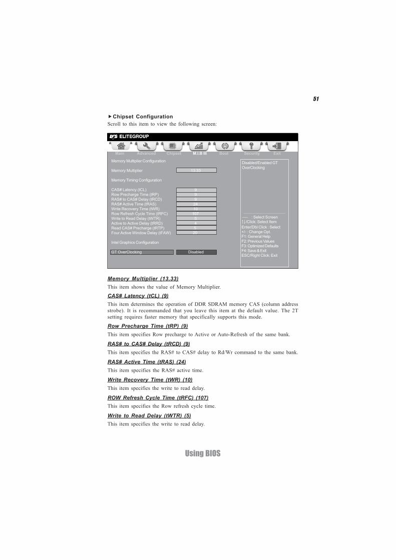
Chipset ConfigurationScroll to this item to view the following screen:
Memory Multiplier (13.33)This item shows the value of Memory Multiplier.
CAS# Latency (tCL) (9)This item determines the operation of DDR SDRAM memory CAS (column addressstrobe). It is recommanded that you leave this item at the default value. The 2Tsetting requires faster memory that specifically supports this mode.
RAS# to CAS# Delay (tRCD) (9)This item specifies the RAS# to CAS# delay to Rd/Wr command to the same bank.
RAS# Active Time (tRAS) (24)This item specifies the RAS# active time.
Row Precharge Time (tRP) (9)This item specifies Row precharge to Active or Auto-Refresh of the same bank.
ROW Refresh Cycle Time (tRFC) (107)This item specifies the Row refresh cycle time.
Main Advanced Chipset M.I.B III Boot Security Exit
+/- : Change Opt.Enter/Dbl Click : Select
: Select Screen/Click: Select Item
F1: General HelpF2: Previous Values
Disabled/Enabled GTOverClocking
F3: Optimized DefaultsF4: Save & ExitESC/Right Click: Exit
Memory Multiplier Configuration
Memory Multiplier 13.33
Memory Timing Configuration
CAS# Latency (tCL) 9Row Precharge Time (tRP) 9RAS# to CAS# Delay (tRCD) 9RAS# Active Time (tRAS) 24Write Recovery Time (tWR) 10Row Refresh Cycle Time (tRFC) 107Write to Read Delay (tWTR) 5Active to Active Delay (tRRD) 4Read CAS# Precharge (tRTP) 5Four Active Window Delay (tFAW) 20
Intel Graphics Configuration
GT OverClocking Disabled
Write Recovery Time (tWR) (10)This item specifies the write to read delay.
Write to Read Delay (tWTR) (5)This item specifies the write to read delay.
52
Using BIOS
Active to Active Delay(tRRD) (4)This item controls the ACTIVE bank x to ACTIVE bank y delay in memory clockcycles.
Read CAS# Precharge (tRTP) (5)This item controls the Read to PRECHARGE delay for memory devices, in memoryclock cycles.
Four Active Window Delay(tFAW) (20)This item controls the four bank activate time in memory clock cycles.GT OverClocking (Disabled)This item allows you to control the internal GFX Turbo mode.
Press <Esc> to return to the Performance Tunning page.
B.O.M.P Technology (Enabled)This item allows users to enable or disable B.O.M.P technology. This function canrun safe setting to setup menu when system boot fail 3 times.
Spread Spectrum (Enabled)If you enable spread spectrum, it can significantly reduce the EMI (Electro-MagneticInterference) generated by the system.
Intel(R) Core(TM) i5-2400 CPU @ 3.10GHzThis is display-only field and displays the information of the CPU installed in yourcomputer.
Processor Speed (3100 MHz)This item shows the CPU speed.
Total Memory (2048MB(DDR3 1333))This item shows the total momery of DDR3.
Auto Detect DIMM/PCI Clk (Enabled)When this item is enabled, BIOS will disable the clock signal of free DIMM/PCI slots.
Command Rate (Auto)This item allows users to set command rate.
Press <Esc> to return to the M.I.B.III Menu page.
53
Using BIOS
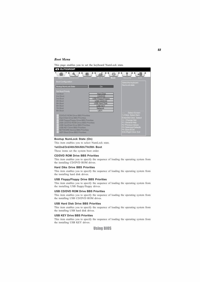
This page enables you to set the keyboard NumLock state.
Boot Menu
Bootup NumLock State (On)This item enables you to select NumLock state.1st/2nd/3rd/4th/5th/6th/7ht/8th BootThese items set the system boot order.
Hard Diks Drive BBS PrioritiesThis item enables you to specify the sequence of loading the operating system fromthe installing hard disk drives.
Main Advanced Chipset M.I.B III Boot Security Exit
+/- : Change Opt.Enter/Dbl Click : Select
: Select Screen/Click: Select Item
F1: General HelpF2: Previous Values
Select the keyboardNumLock state
F3: Optimized DefaultsF4: Save & ExitESC/Right Click: Exit
Boot Configuration
Bootup NumLock State On
Set Boot Priority1st Boot Hard Disk2nd Boot CD/DVD3rd Boot USB Floppy/Floppy4th Boot USB CD/DVD5th Boot USB Hard Disk6th Boot USB KEY7th Boot Network8th Boot UEFI
CD/DVD ROM Drive BBS Priorities Hard Disk Drive BBS Priorities USB Floppy/Floppy Drive BBS Priorities USB CD/DVD ROM Drive BBS Priorities USB HardDisk Drive BBS Priorities USB KEY Drive BBS Priorities
NETWORK Device BBS Priorities UEFI Boot Drive BBS Priorities
CD/DVD ROM Drive BBS PrioritiesThis item enables you to specify the sequence of loading the operating system fromthe installing CD/DVD ROM drives.
USB Floppy/Floppy Drive BBS PrioritiesThis item enables you to specify the sequence of loading the operating system fromthe installing USB floppy/floppy drives.
USB Hard Disk Drive BBS PrioritiesThis item enables you to specify the sequence of loading the operating system fromthe installing USB hard disk drives.
USB KEY Drive BBS PrioritiesThis item enables you to specify the sequence of loading the operating system fromthe installing USB KEY drives.
USB CD/DVD ROM Drive BBS PrioritiesThis item enables you to specify the sequence of loading the operating system fromthe installing USB CD/DVD ROM drives.
54
Using BIOS
Main Advanced Chipset M.I.B III Boot Security Exit
Set Setup AdministratorPassword
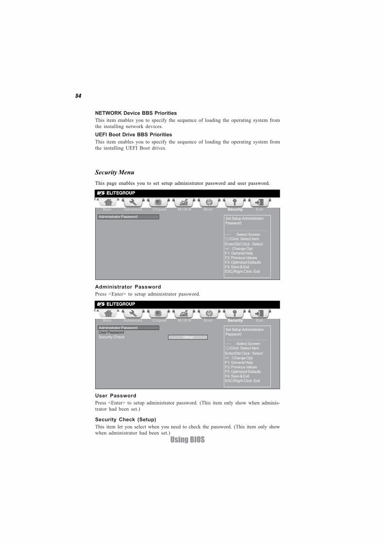
This page enables you to set setup administrator password and user password.
Security Menu
Administrator PasswordPress <Enter> to setup administrator password.
Main Advanced Chipset M.I.B III Boot Security Exit
+/- : Change Opt.Enter/Dbl Click : Select
: Select Screen/Click: Select Item
F1: General HelpF2: Previous Values
Set Setup AdministratorPassword
F3: Optimized DefaultsF4: Save & ExitESC/Right Click: Exit
Administrator Password
NETWORK Device BBS PrioritiesThis item enables you to specify the sequence of loading the operating system fromthe installing network devices.UEFI Boot Drive BBS PrioritiesThis item enables you to specify the sequence of loading the operating system fromthe installing UEFI Boot drives.
Administrator PasswordUser PasswordSecurity Check Setup
+/- : Change Opt.Enter/Dbl Click : Select
: Select Screen/Click: Select Item
F1: General HelpF2: Previous ValuesF3: Optimized DefaultsF4: Save & ExitESC/Right Click: Exit
User PasswordPress <Enter> to setup administrator password. (This item only show when adminis-trator had been set.)
Security Check (Setup)This item let you select when you need to check the password. (This item only showwhen administrator had been set.)
55
Using BIOS
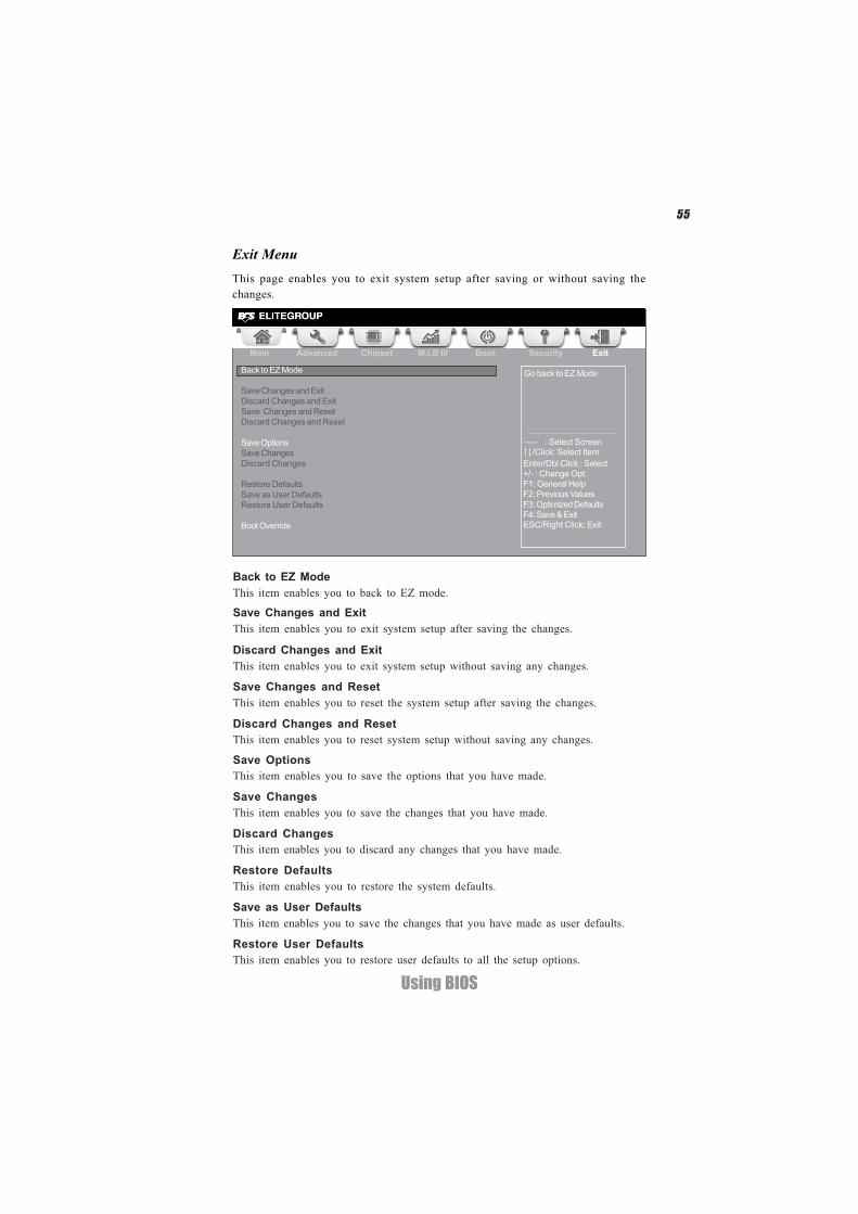
Save OptionsThis item enables you to save the options that you have made.
Save ChangesThis item enables you to save the changes that you have made.
Discard ChangesThis item enables you to discard any changes that you have made.
Restore DefaultsThis item enables you to restore the system defaults.
Save as User DefaultsThis item enables you to save the changes that you have made as user defaults.
Restore User DefaultsThis item enables you to restore user defaults to all the setup options.
Save Changes and ExitThis item enables you to exit system setup after saving the changes.
Discard Changes and ExitThis item enables you to exit system setup without saving any changes.
Save Changes and ResetThis item enables you to reset the system setup after saving the changes.
Discard Changes and ResetThis item enables you to reset system setup without saving any changes.
This page enables you to exit system setup after saving or without saving thechanges.
Exit Menu
Main Advanced Chipset M.I.B III Boot Security Exit
+/- : Change Opt.Enter/Dbl Click : Select
: Select Screen/Click: Select Item
F1: General HelpF2: Previous Values
Go back to EZ Mode
F3: Optimized DefaultsF4: Save & ExitESC/Right Click: Exit
Back to EZ Mode
Save Changes and ExitDiscard Changes and ExitSave Changes and ResetDiscard Changes and Reset
Save OptionsSave ChangesDiscard Changes
Restore DefaultsSave as User DefaultsRestore User Defaults
Boot Override
Back to EZ ModeThis item enables you to back to EZ mode.

56
Using BIOS
Boot OverrideUse this item to select the boot device.
57
Using BIOS
Updating the BIOSYou can download and install updated BIOS for this motherboard from themanufacturer’s Website. New BIOS provides support for new peripherals, improve-ments in performance, or fixes for known bugs. Install new BIOS as follows:
This concludes Chapter 3. Refer to the next chapter for information on the softwaresupplied with the motherboard.
1 If your motherboard has a BIOS protection jumper, change the setting toallow BIOS flashing.
2 If your motherboard has an item called Firmware Write Protect in Ad-vanced BIOS features, disable it. (Firmware Write Protect preventsBIOS from being overwritten.)
3 Prepare a bootable device or create a bootable system disk. (Refer toWindows online help for information on creating a bootable systemdisk.)
4 Download the Flash Utility and new BIOS file from the manufacturer’sWeb site. Copy these files to the bootable device.
5 Turn off your computer and insert the bootable device in your com-puter. (You might need to run the Setup Utility and change the bootpriority items on the Advanced BIOS Features Setup page, to forceyour computer to boot from the bootable device first.)
6 At the C:\ or A:\ prompt, type the Flash Utility program name and the filename of the new BIOS and then press <Enter>. Example: AFUDOS.EXE040706.ROM
7 When the installation is complete, remove the bootable device from thecomputer and restart your computer. If your motherboard has a FlashBIOS jumper, reset the jumper to protect the newly installed BIOS frombeing overwritten. The computer will restart automatically.

58
Using BIOS
Memo
59
Using the Motherboard Software
Chapter 4
Using the Motherboard Software
Auto-installing under Windows XP/Vista/7The Auto-install DVD-ROM/CD-ROM makes it easy for you to install the driversand software for your motherboard.
If the Auto-install DVD-ROM/CD-ROM does not work on your system,you can still install drivers through the file manager for your OS (forexample, Windows Explorer). Refer to the Utility Folder Installation Noteslater in this chapter.
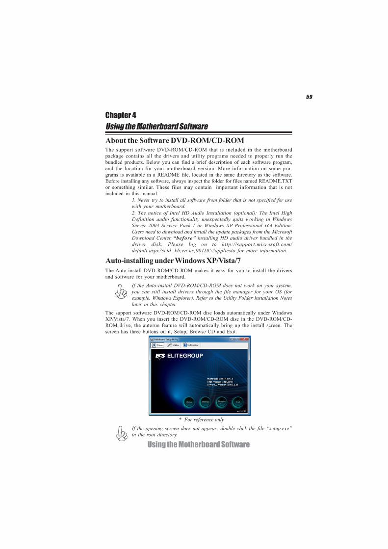
The support software DVD-ROM/CD-ROM disc loads automatically under WindowsXP/Vista/7. When you insert the DVD-ROM/CD-ROM disc in the DVD-ROM/CD-ROM drive, the autorun feature will automatically bring up the install screen. Thescreen has three buttons on it, Setup, Browse CD and Exit.
If the opening screen does not appear; double-click the file “setup.exe”in the root directory.
About the Software DVD-ROM/CD-ROMThe support software DVD-ROM/CD-ROM that is included in the motherboardpackage contains all the drivers and utility programs needed to properly run thebundled products. Below you can find a brief description of each software program,and the location for your motherboard version. More information on some pro-grams is available in a README file, located in the same directory as the software.Before installing any software, always inspect the folder for files named README.TXTor something similar. These files may contain important information that is notincluded in this manual.
2. The notice of Intel HD Audio Installation (optional): The Intel HighDefinition audio functionality unexpectedly quits working in WindowsServer 2003 Service Pack 1 or Windows XP Professional x64 Edition.Users need to download and install the update packages from the MicrosoftDownload Center “before” installing HD audio driver bundled in thedriver disk. Please log on to http://support.microsoft.com/default.aspx?scid=kb;en-us;901105#appliesto for more information.
1. Never try to install all software from folder that is not specified for usewith your motherboard.
* For reference only
60
Using the Motherboard Software
Drivers
Setup Click the Setup button to run the software installation program.Select from the menu which software you want to install.
Browse CD The Browse CD button is the standard Windows command thatallows you to open Windows Explorer and show the contents of thesupport disk.
Before installing the software from Windows Explorer, look for a filenamed README.TXT or something similar. This file may containimportant information to help you install the software correctly.
Some software is installed in separate folders for different operatingsystems.
In installing the software, execute a file named SETUP.EXE by double-clicking the file and then following the instructions on the screen.
Exit The EXIT button closes the Auto Setup window.
UtilitiesLists the software utilities that are available on the disk.
InformationDisplays the path for all software and drivers available on the disk.
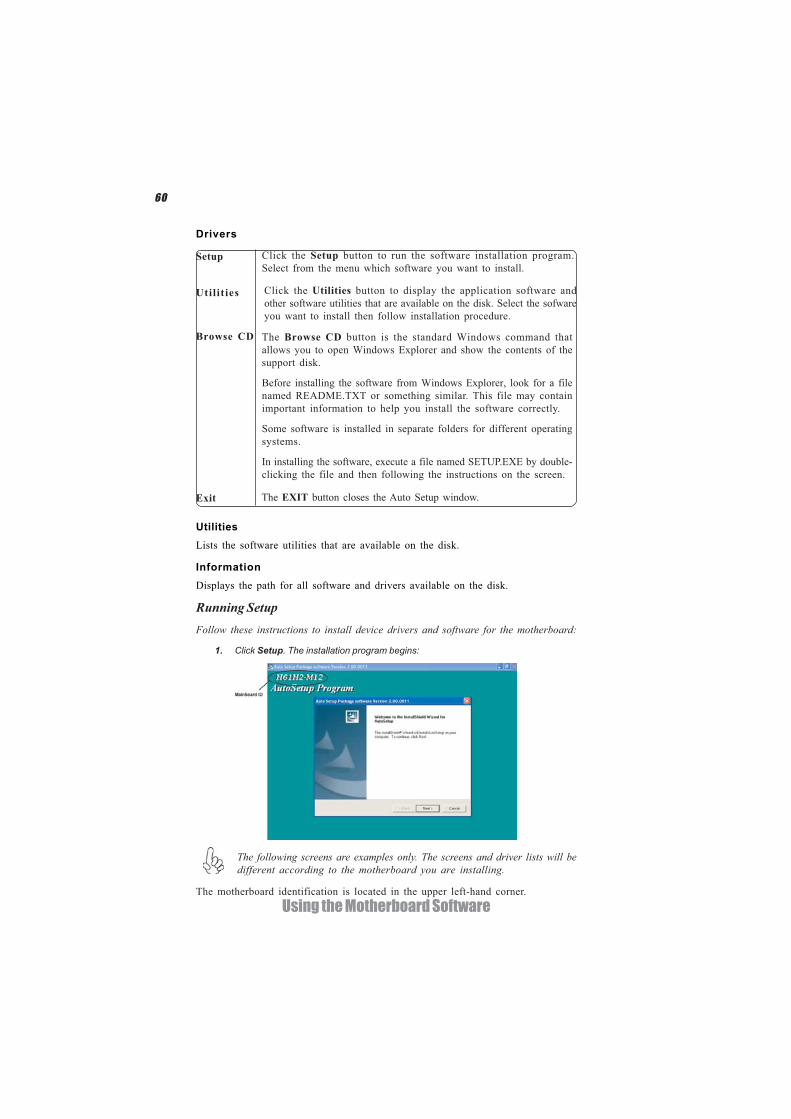
Running SetupFollow these instructions to install device drivers and software for the motherboard:
1. Click Setup. The installation program begins:
The following screens are examples only. The screens and driver lists will bedifferent according to the motherboard you are installing.
The motherboard identification is located in the upper left-hand corner.
Utilities Click the Utilities button to display the application software andother software utilities that are available on the disk. Select the sofwareyou want to install then follow installation procedure.
61
Using the Motherboard Software
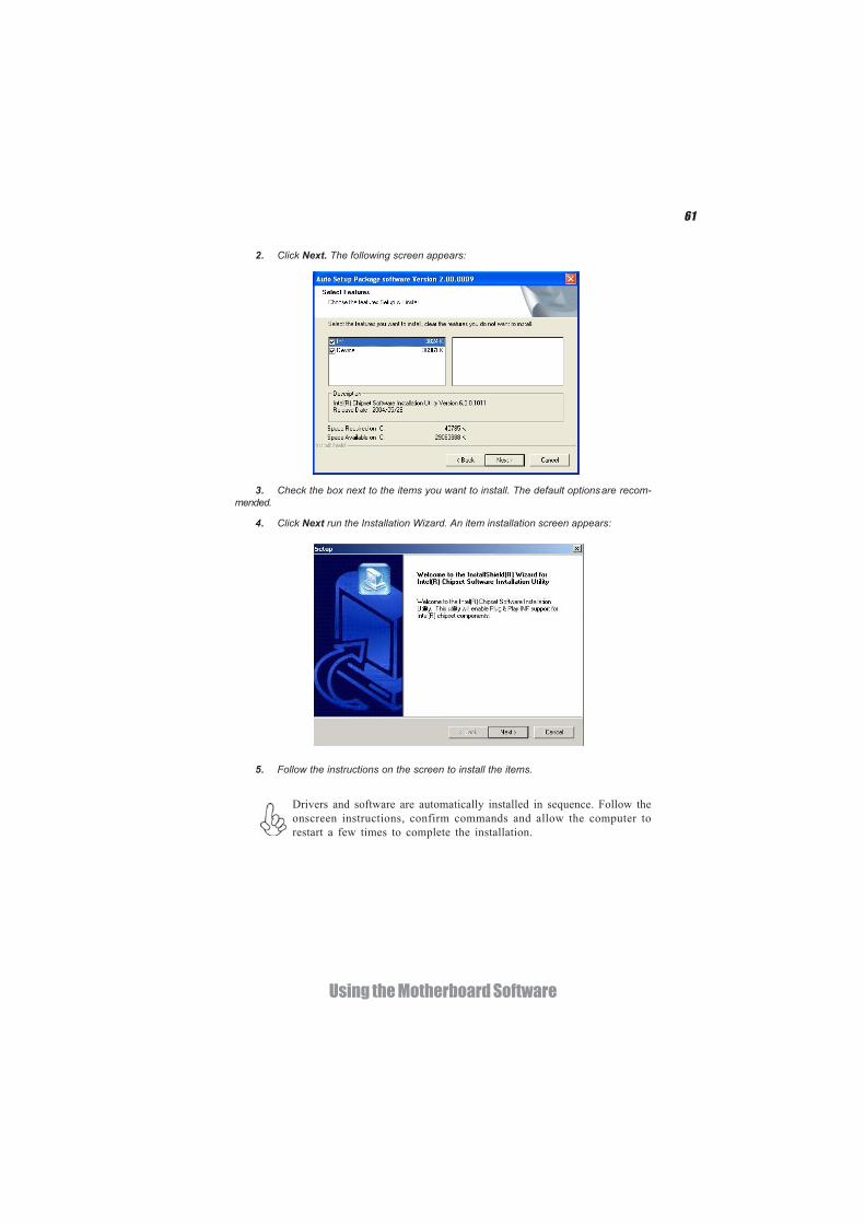
2. Click Next. The following screen appears:
3. Check the box next to the items you want to install. The default optionsare recom-mended.
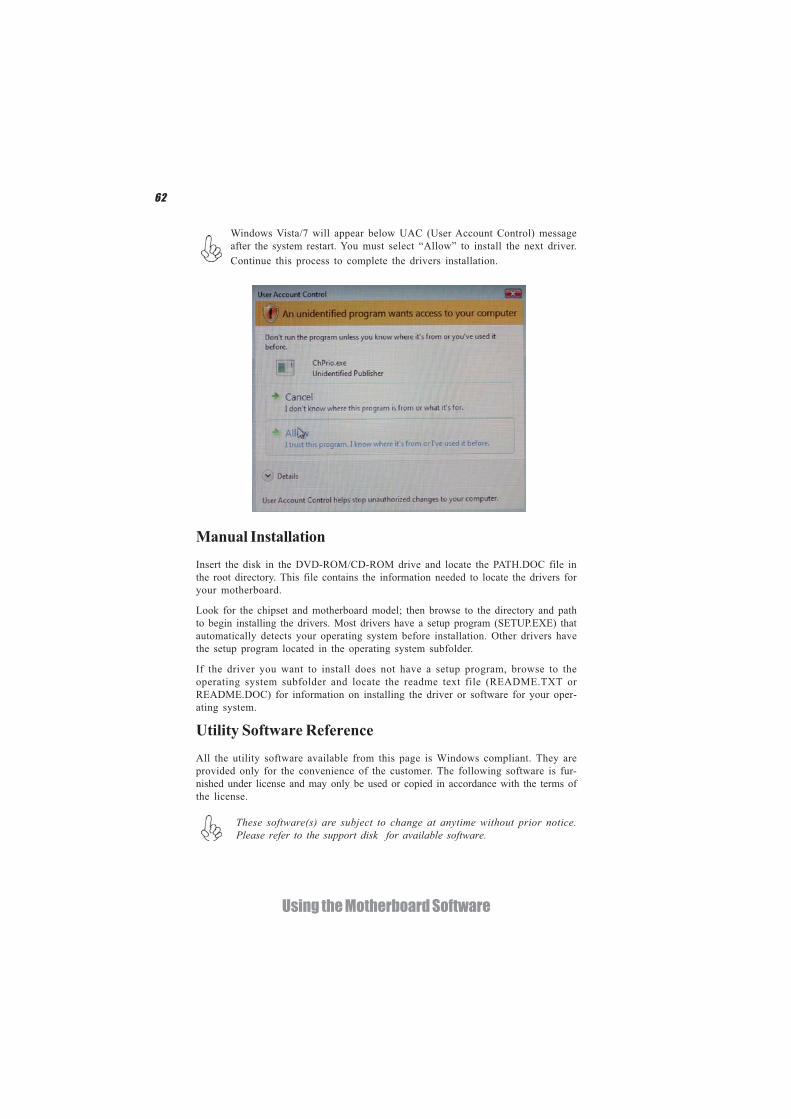
4. Click Next run the Installation Wizard. An item installation screen appears:
5. Follow the instructions on the screen to install the items.
Drivers and software are automatically installed in sequence. Follow theonscreen instructions, confirm commands and allow the computer torestart a few times to complete the installation.
62
Using the Motherboard Software
Manual InstallationInsert the disk in the DVD-ROM/CD-ROM drive and locate the PATH.DOC file inthe root directory. This file contains the information needed to locate the drivers foryour motherboard.
Look for the chipset and motherboard model; then browse to the directory and pathto begin installing the drivers. Most drivers have a setup program (SETUP.EXE) thatautomatically detects your operating system before installation. Other drivers havethe setup program located in the operating system subfolder.
If the driver you want to install does not have a setup program, browse to theoperating system subfolder and locate the readme text file (README.TXT orREADME.DOC) for information on installing the driver or software for your oper-ating system.
Utility Software ReferenceAll the utility software available from this page is Windows compliant. They areprovided only for the convenience of the customer. The following software is fur-nished under license and may only be used or copied in accordance with the terms ofthe license.
These software(s) are subject to change at anytime without prior notice.Please refer to the support disk for available software.
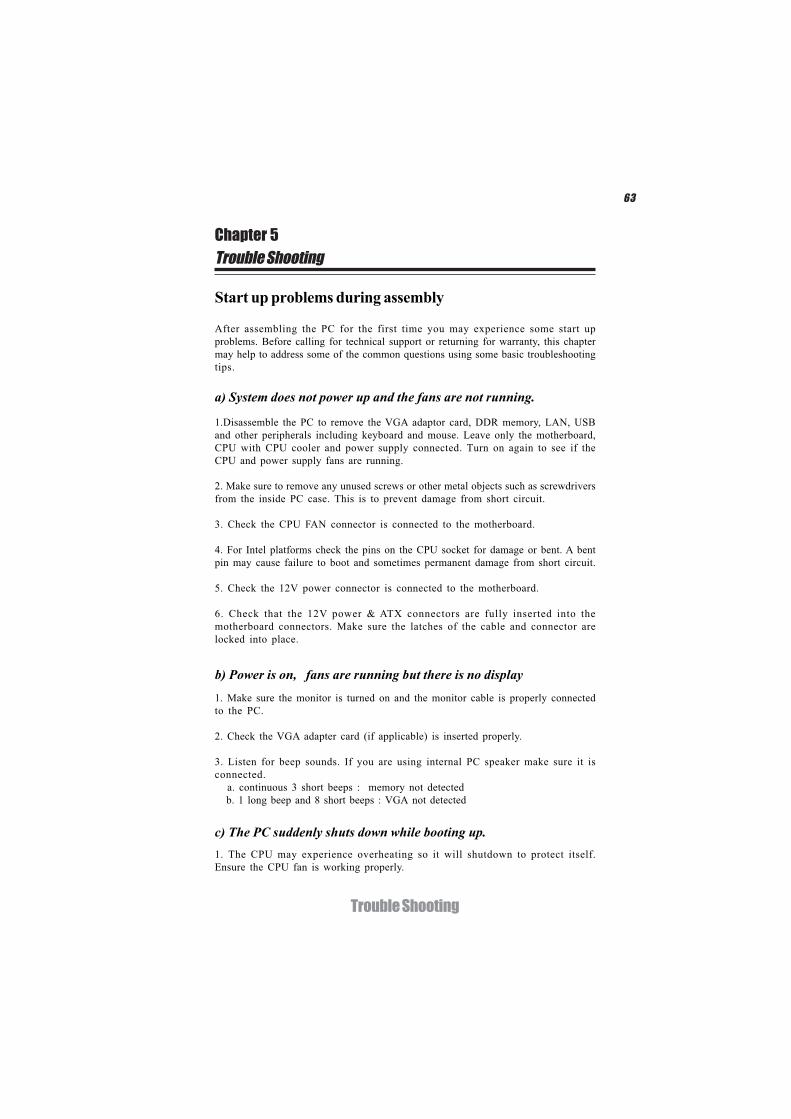
Windows Vista/7 will appear below UAC (User Account Control) messageafter the system restart. You must select “Allow” to install the next driver.Continue this process to complete the drivers installation.
63
Trouble Shooting
Chapter 5
Trouble Shooting
Start up problems during assembly
After assembling the PC for the first time you may experience some start upproblems. Before calling for technical support or returning for warranty, this chaptermay help to address some of the common questions using some basic troubleshootingtips.
a) System does not power up and the fans are not running.
1.Disassemble the PC to remove the VGA adaptor card, DDR memory, LAN, USBand other peripherals including keyboard and mouse. Leave only the motherboard,CPU with CPU cooler and power supply connected. Turn on again to see if theCPU and power supply fans are running.
2. Make sure to remove any unused screws or other metal objects such as screwdriversfrom the inside PC case. This is to prevent damage from short circuit.
3. Check the CPU FAN connector is connected to the motherboard.
4. For Intel platforms check the pins on the CPU socket for damage or bent. A bentpin may cause failure to boot and sometimes permanent damage from short circuit.
5. Check the 12V power connector is connected to the motherboard.
6. Check that the 12V power & ATX connectors are fully inserted into themotherboard connectors. Make sure the latches of the cable and connector arelocked into place.
b) Power is on, fans are running but there is no display
1. Make sure the monitor is turned on and the monitor cable is properly connectedto the PC.
2. Check the VGA adapter card (if applicable) is inserted properly.
3. Listen for beep sounds. If you are using internal PC speaker make sure it isconnected. a. continuous 3 short beeps : memory not detected b. 1 long beep and 8 short beeps : VGA not detected
c) The PC suddenly shuts down while booting up.1. The CPU may experience overheating so it will shutdown to protect itself.Ensure the CPU fan is working properly.
64
Trouble Shooting
Your computer, like any electrical appliance, requires proper care and maintenance.Here are some basic PC care tips to help prolong the life of the motherboard andkeep it running as best as it can.
1. Keep your computer in a well ventilated area. Leave some space between the PC and the wall for sufficient airflow.
2. Keep your computer in a cool dry place. Avoid dusty areas, direct sunlight
Start up problems after prolong useAfter a prolong period of use your PC may experience start up problems again.This may be caused by breakdown of devices connected to the motherboard such asHDD, CPU fan, etc. The following tips may help to revive the PC or identify thecause of failure.1. Clear the CMOS values using the CLR_CMOS jumper. Refer to CLR_CMOSjumper in Chapter 2 for Checking Jumper Settings in this user manual. Whencompleted, follow up with a Load Optimised Default in the BIOS setup.
2. Check the CPU cooler fan for dust. Long term accumulation of dust will reduceits effectiveness to cool the processor. Clean the cooler or replace a new one ifnecessary.
3. Check that the 12V power & ATX connectors are fully inserted into themotherboard connectors. Make sure the latches of the cable and connector arelocked into place.
4. Remove the hard drive, optical drive or DDR memory to determine which ofthese components may be at fault.
and areas of high moisture content.
3. Routinely clean the CPU cooler fan to remove dust and hair.
4. In places of hot and humid weather you should turn on your computer once every other week to circulate the air and prevent damage from humidity.
5. Add more memory to your computer if possible. This not only speeds up the system but also reduces the loading of your hard drive to prolong its life span.
6. If possible, ensure the power cord has an earth ground pin directly from the wall outlet. This will reduce voltage fluctuation that may damage sensitive devices.
Maintenance and care tips
2. From the BIOS setting, try to disable the Smartfan function to let the fan run atdefault speed. Doing a Load Optimised Default will also disable the Smartfan.
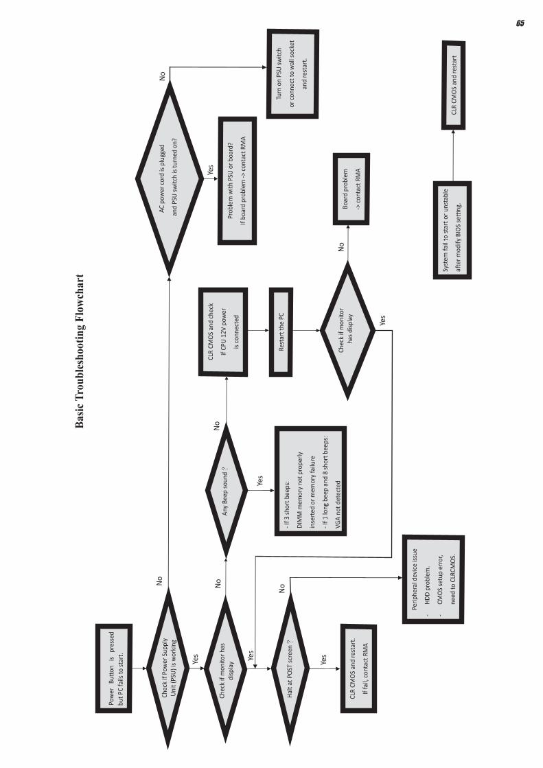
Pow
er
Buon
is
pr
esse
d bu
t PC
fails
to st
art.
Yes
Chec
k if
Pow
er S
uppl
y U
nit (
PSU
) is
wor
king
No
No
Any
Beep
sou
nd?
N
o CL
R CM
OS
and
chec
k
if CP
U 1
2V p
ower
is c
onne
cted
art t
he P
C st
Re
Prob
lem
with
PSU
or b
oard
?
If bo
ard
prob
lem
-> c
onta
ct R
MA
AC p
ower
cor
d is
plu
ed
gg
and
PSU
switc
h is
turn
ed o
n?
Yes
oble
m
rBo
ard
p
-> c
onta
ct R
MA
No
- If 3
sho
rt b
eeps
:
DIM
M m
emor
y no
t pro
perly
inse
rted
or m
emor
y fa
ilure
- If 1
long
bee
p an
d 8
shor
t bee
ps:
VGA
not d
etec
ted
Yes
Yes
Hal
t at P
OST
scr
een?
Yes
R CM
OLC
S an
d re
star
t.
If fa
il, c
onta
ct R
MA
Yes
No
Perip
hera
l dev
ice
issu
e
-H
DD
pro
blem
.
-CM
OS
setu
p er
ror,
dne
e to
CLR
CMO
S.
Syst
em fa
il to
sta
rt o
r uns
tabl
e
aer
mod
ify B
IOS
seng
. M
CLR
CO
S an
d re
star
t
Turn
on
PSU
sw
itch
or c
onne
ct to
wal
l soc
ket
star
t. e
and
rNo
Chec
k if
mon
itor h
sadi
s pla
y
Chec
k if
mon
itor
has
dis
play
65
Basic
Tro
uble
shoo
ting
Flow
char
t

66
Trouble Shooting
Memo