Embed Size (px)
DESCRIPTION
H6 Beam Tests Analysis Studies. H6 LAr calorimetry beam tests Signal reconstruction Response to electrons Electromagnetic Scale Response to pions weighting schemes Simulation Conclusion and outlook. 1st North American ATLAS Physics Workshop 19-21 December 2004, Tucson, Arizona. - PowerPoint PPT Presentation
Citation preview

M. Lefebvre H6 Beam Tests Analysis 1
H6 Beam Tests Analysis Studies
H6 LAr calorimetry beam tests Signal reconstruction Response to electrons
Electromagnetic Scale
Response to pions weighting schemes
Simulation Conclusion and outlook
Michel Lefebvre University of Victoria Physics and Astronomy
1st North American ATLAS Physics Workshop
19-21 December 2004, Tucson, Arizona

M. Lefebvre H6 Beam Tests Analysis 2
ATLAS LAr and Tile CalorimetersTile barrel Tile extended barrel
LAr forward calorimeter (FCal)
LAr hadronic end-cap (HEC)
LAr EM end-cap (EMEC)
LAr EM barrel

M. Lefebvre H6 Beam Tests Analysis 3
Design Physics Requirements EM Calorimeters
Benchmark channels H and H ZZ eeee require high resolution at 100 GeV and coverage to low ET
b-physics: e reconstruction down to GeV range Dynamic range: MIP to Z’ ee at a few TeV Design goals for || < 2.5
(E)/E = 8-11 %/E 0.2-0.4/E 0.7%
• Linearity better that 0.1%
Hadron and Forward Calorimeters Benchmark channels H WW jet jet X and Z/W/t require good
jet-jet mass resolution Higgs fusion good forward jet tagging ETmiss jet resolution and linearity
Design goals (E)/E = 50%/E 3% for || < 3 (E)/E = 50%/E 10% for 3 < || < 5

M. Lefebvre H6 Beam Tests Analysis 4
EM Endcap
EM Barrel
Hadronic Endcap
ForwardTile Barrel
Tile Extended Barrel
LAr Calorimeters EM Barrel
|| < 1.5
EMEC 1.4 < || < 3.2
HEC 1.5 < || < 3.2
FCal 3.1 < || < 4.9

M. Lefebvre H6 Beam Tests Analysis 5
Electromagnetic Endcap Calorimeter
EMEC absorber structure Pb absorbers arranged radially, no azimuthal cracks folding angle and wave amplitude vary with radius inner and outer wheels
EMEC readout structure layer 0 (presampler)
= 0.025 0.1
layer 1 (front): 2 to 4 Xo
= 0.025/8 0.1
layer 2 (middle): 16 to 18 Xo
= 0.025 0.025
layer 3 (back): 2 to 4 Xo
= 0.050 0.025

M. Lefebvre H6 Beam Tests Analysis 6
Hadronic Endcap Calorimeter
HEC absorber structure Cu absorbers in the transverse plane front and back wheels, 2 samplings each EST readout structure
HEC readout structure 1.5 < || < 2.5 = 0.1 0.1 2.5 < || < 3.3 = 0.2 0.2

M. Lefebvre H6 Beam Tests Analysis 7
Forward Calorimeter
Type AbsorberGap
(μm)Number of Electrodes
FCal1 EM copper 250 12000
FCal2 HAD tungsten 375 10000
FCal3 HAD tungsten 500 8000
FCal absorber structure Cu (FCal1) and W (FCal2/3) absorber with cylindrical ionization
chambers parallel to the beam line
FCal readout structure Principal coverage is 3.1 < || < 4.9 and 0.2 0.2 Non-projective!

M. Lefebvre H6 Beam Tests Analysis 8
LAr Bipolar Signal Pulse Shaping
equal areas
Amplitude carries the information (i0)
physics pulse
Optimal shaping time is an optimization problem between electronics noise and pileup noise
Pulse shape sampled every 25 ns
M. Lefebvre H6 Beam Tests Analysis 9
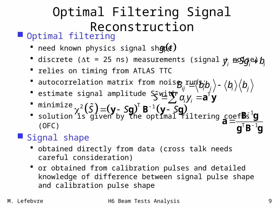
Optimal Filtering Signal Reconstruction Optimal filtering
need known physics signal shape
discrete (t = 25 ns) measurements (signal + noise):
relies on timing from ATLAS TTC
autocorrelation matrix from noise runs:
estimate signal amplitude S with
minimize
solution is given by the optimal filtering coeffs (OFC)
Signal shape obtained directly from data (cross talk needs careful
consideration) or obtained from calibration pulses and detailed knowledge of
difference between signal pulse shape and calibration pulse shape
g t
i i iy Sg b
ij i j i jB bb b b T
i iS a y a y
T2 1S S S y g B y g1
T 1
B ga
g B g

M. Lefebvre H6 Beam Tests Analysis 10
All LAr detectors have calibration pulser system EM
Inject on summing boards
HEC Inject at
calo pads
FCal Inject on FEB
backplane
To use calibration system: Understanding Understanding
ADC[phys]/ADC[cal] ADC[phys]/ADC[cal]
for fixedfor fixed I I00 is key is key
PhysicsPhysics
CalibrationCalibration
Same Same II00

M. Lefebvre H6 Beam Tests Analysis 11
Hadronic Energy Reconstruction Hadronic shower consists of
EM energy (eg 0) : O(50%)
Visible non-EM energy (eg dE/dX) : O(25%)
Invisible non-EM energy (eg nuclear breakup) : O(25%)
Escaped energy (eg ) : O(2%) Goal:
Event-by-event offline compensation of hadronic energy deposition
Improve linearity and resolution

M. Lefebvre H6 Beam Tests Analysis 12
I nt r insic E lect r omagnet ic E ner gy S cale S ignal
F undament al Calor imet er S ignal Defi nit ion:Cell Level and T opological N oise Cut s
I nt er mediat e Calor imet er S ignal Defi nit ion:Cell Clust er F or mat ion
A dvanced Calor imet er S ignal Defi nit ion:Clust er Classifi cat ion
E lect r omagnet icClust er
N on- c lassifi edClust er
H adr onicClust er
F inal Local E ner gy S cale S ignal
Quality of T
rue Deposited
Energy E
stimate
Electronic and readout effects Electronic and readout effects unfolded (nA->GeV calibration)unfolded (nA->GeV calibration)
Detector noise suppression Detector noise suppression algorithms (optional, can be algorithms (optional, can be absorbed into cluster absorbed into cluster formation algorithm)formation algorithm)
Cluster formation in Cluster formation in calorimeter regions (2D-calorimeter regions (2D->3D->spanning regions)>3D->spanning regions)
Simple cluster shape Simple cluster shape analysis -> classificationanalysis -> classification
Apply cluster type specific Apply cluster type specific calibration functions, dead calibration functions, dead material and crack material and crack correctionscorrections
Best estimate for general Best estimate for general energy flow in event -> re-energy flow in event -> re-calibrate smallest readout calibrate smallest readout units (cells)!units (cells)!
Model II: Local Calorimeter Calibration Algorithm FlowModel II: Local Calorimeter Calibration Algorithm FlowModel II: Local Calorimeter Calibration Algorithm FlowModel II: Local Calorimeter Calibration Algorithm FlowP. Loch
M. Lefebvre H6 Beam Tests Analysis 13
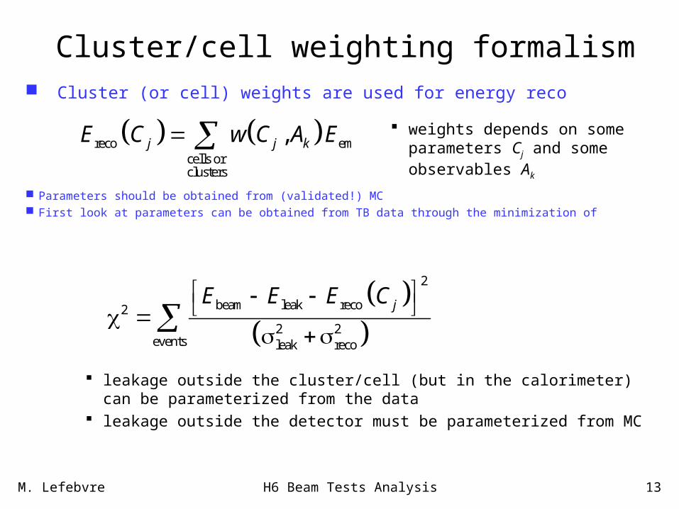
Cluster/cell weighting formalism
Cluster (or cell) weights are used for energy reco
2
beam leak reco2
2 2events leak reco
jE E E C
reco emcells orclusters
,j j kE C w C A E weights depends on some parameters Cj and some observables Ak
Parameters should be obtained from (validated!) MC First look at parameters can be obtained from TB data through the minimization of
leakage outside the cluster/cell (but in the calorimeter) can be parameterized from the data
leakage outside the detector must be parameterized from MC

M. Lefebvre H6 Beam Tests Analysis 14
H6 beam tests HEC standalone (1998-2001) EM scale EMEC standalone (1999) EM scale, presampler EMEC-HEC (2002) combined pion response FCal standalone (2003) Fcal calibration EMEC-HEC-FCAL (2004) combined forward response
The tests serve multiple purposes, including QA/QC during detector construction EM scale calibration Investigate hadronic shower reconstruction scheme Study detector interface regions Exercise ATLAS electronics chain Tests of online/offline monitoring/reconstruction software

M. Lefebvre H6 Beam Tests Analysis 15
Combined beam tests
EM Endcap
EM Barrel Hadronic Endcap
Forward
Tile BarrelTile Extended
Barrel
2004 H8 Barrel CTB2004 H8 Barrel CTB
2002 H62002 H6EMEC/HECEMEC/HEC
2004 H62004 H6EMEC/EMEC/
HEC/FCALHEC/FCAL
2003 H62003 H6FCALFCAL

M. Lefebvre H6 Beam Tests Analysis 16
HEC-EMEC: beam test configuration
H6 beam area at the CERN SPS e, , beams with 6 GeV E 200 GeV 90o impact angle: non-pointing setup (not like ATLAS)
PS+EMEC
HEC
beam position chambers optional additional material upstream
(presampler studies)

M. Lefebvre H6 Beam Tests Analysis 17
EMEC-HEC: H6 beamline
front face of HEC seen through the EMEC
detector
cryostat moves laterally 30 cm
bending magnet steers beam in y
beamline trigger scintillators and tracking detectors

M. Lefebvre H6 Beam Tests Analysis 18
EMEC and HEC Signal Reconstruction Steps
Relate calibration pulse shape with physics pulse shape use electronics model (from simple model to full simulation) extract model parameters (various techniques)
Use predicted physics pulse shape and noise autocorrelation matrix to obtain OFC physics pulse shape not available for all channels!
Use calibration (ramp) runs to calibrate current DAC R nA DAC ADC[cal] ADC[phys]
Obtain EM scale from beam test or simulation nA MeV
Accuracy and channel uniformity goals EM: 0.5% and HEC: 1%
M. Lefebvre H6 Beam Tests Analysis 19
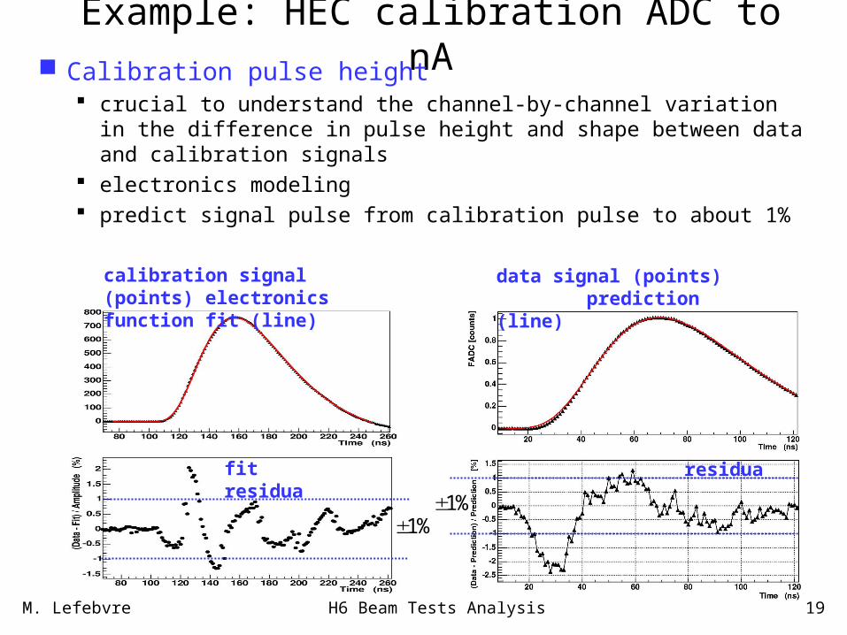
Example: HEC calibration ADC to nA Calibration pulse height
crucial to understand the channel-by-channel variation in the difference in pulse height and shape between data and calibration signals
electronics modeling predict signal pulse from calibration pulse to about 1%
calibration signal (points) electronics function fit (line)
fit residua
1%
data signal (points) prediction (line)
residua
1%

M. Lefebvre H6 Beam Tests Analysis 20
EMEC-HEC: electronic noise Electronic noise obtained directly from data
EMEC: use muon data and remove hit cells HEC: use first 5 time samples (which are out of signal region)
25.8 MeV EM scale
327 MeV EM scale

M. Lefebvre H6 Beam Tests Analysis 21
EMEC-HEC: Clustering
Cell-based topological nearest neighbor cluster algorithm clusters are formed per
layer using neighbours (that share at least one corner)
Eseed > 4noise
|Ecell| > 2noise
include neighbour cells with |Ecell| > 3noise
180 GeV pion
nA
nA

M. Lefebvre H6 Beam Tests Analysis 22
EMEC-HEC: electron response
phi-modulation correction, and resulting phi-resolution electric field and sampling fraction non-uniformities non-pointing setup well understood
beambeam
A B CEE
ABC
3 absorbers

M. Lefebvre H6 Beam Tests Analysis 23
EMEC-HEC: electromagnetic scale Needed as reference for hadronic calibration Obtained from beam test data
beam dep leak reco leakE E E E E EMEC EMEC EMEC
reco em em visE E I
beam leakEMECem EMEC
vis
0.430 0.001 0.009 MeV/nA
E E
I
where
The leakage is only outside the cluster, hence measurable. It is < 3% for Ebeam > 30 GeV
signal shape uncertainties and dependent corrections which have not been applied
Linearity better than 0.5%
Include 2% -dependent geometrical response corrections

M. Lefebvre H6 Beam Tests Analysis 24
EMEC-HEC: pions response Use HEC EM scale from previous TB, modified by new
electronics, and EMEC EM scale obtained here
Example: 120 GeV pions in EM scale
EMECem
HECem
0.430 0.001 0.009 MeV/nA
3.27 0.03 0.03 MeV/nA
HECEMECHECemE
EMECemE
EMEC EMEC EMECem em vis
HEC HEC HECem em vis
E I
E I

M. Lefebvre H6 Beam Tests Analysis 25
EMEC-HEC: beam energy dependent cluster weights
Consider 3D topological clusters Use cluster energy density as observable Use simple weight function, à la H1
E H E E EMEC H H HECreco em em
EMEC HEC clusters clusters
, , ,j j j jE C C w C E w C E
1 2 3, expjw C C C C
Significant improvement of energy resolution Results published [NIM A531 (2004) 481-
514] uses fixed C2 values Electronics noise subtracted in quadrature

M. Lefebvre H6 Beam Tests Analysis 26
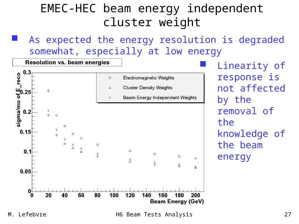
EMEC-HEC beam energy independent cluster weight The knowledge of the beam energy must be taken out! First look at beam energy independent cluster weights
Use beam energy to produce weight parameterization Estimate beam energy using cluster energy In general one pion corresponds to many clusters Use 2
1 2 3, expjw C C C C
M. Lefebvre H6 Beam Tests Analysis 27
EMEC-HEC beam energy independent cluster weight
As expected the energy resolution is degraded somewhat, especially at low energy
Linearity of response is not affected by the removal of the knowledge of the beam energy

M. Lefebvre H6 Beam Tests Analysis 28
Cell weights Weights can also be applied at cell level
thought to be more flexible and more adapted to ATLAS
cell weights can depend on cluster observables energy and energy density cluster shape distance of cell from shower axis, etc.
Initial attempts (EMEC-HEC NIM) only used energy density weights obtained from data results comparable to cluster weights
Recent attempts includes more observables and MCrecocell cell
em non-em vis non-em invis escapedcell cell cell cell
em non-em viscell cell
E wE
E E E Ew
E E
M. Lefebvre H6 Beam Tests Analysis 29
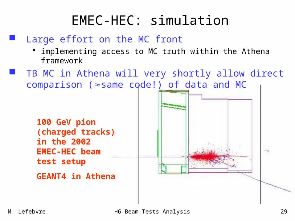
EMEC-HEC: simulation Large effort on the MC front
implementing access to MC truth within the Athena framework
TB MC in Athena will very shortly allow direct comparison (same code!) of data and MC
100 GeV pion (charged tracks) in the 2002 EMEC-HEC beam test setup
GEANT4 in Athena

M. Lefebvre H6 Beam Tests Analysis 30
EMEC-HEC: cell weights Initial work on cell weighting promising...
weights obtained from MC only
... but still work in progress understand data/MC differences understand bias in reconstructing EM showers energy linearity
DATA 80 GeV pion MC 80 GeV pion

M. Lefebvre H6 Beam Tests Analysis 31
Evacuated “beam pipe”
FCal1 FCal2 FCal3
FCal 2003 beam test configuration
energy scans
position scan
H6 beam area at the CERN SPS use beams with 10 GeV E 200 GeV use e beams with 5 GeV E 200 GeV
Programme energy scal at = 3.7 position scan toward
inner edge

M. Lefebvre H6 Beam Tests Analysis 32
FCal Signal Reconstruction Steps Use direct physics pulse shape accumulation from
beam test to obtain OFC Use beam test and/or MC to normalize the energy scale
ADC[phys] MeV That is, calibration system is not yet used directly
Accuracy and channel uniformity FCal: a few %
Calibration system used for FEB stability monitoring Investigations in progress
about use of reflection pulse data points in black

M. Lefebvre H6 Beam Tests Analysis 33
FCal1
FCal2
FCal3
FCAL energy deposits from 200 GeV ’s (accumulated)

M. Lefebvre H6 Beam Tests Analysis 34
193.1 GeVZpa=30
FCAL energy reconstruction for electrons
Energy sum within a cylinder of radius Rcyl
More sophisticated clustering available in common atlas software framework (athena)
Rcyl

M. Lefebvre H6 Beam Tests Analysis 35
FCal electron response 10, 20 and 40 GeV

M. Lefebvre H6 Beam Tests Analysis 36
FCal electron and linearity
very preliminary

M. Lefebvre H6 Beam Tests Analysis 37
FCal electron energy resolution
E (GeV)
σ/E
(%
)
b c
σ/E aEE
a=(3.760.06)%, b=(24.50.84)GeV %, c=(145.51.6) GeV%

M. Lefebvre H6 Beam Tests Analysis 38
FCal pion energy resolutionCurrent pion results involve rather simple analysis:
Reconstruction using EM scale with relative sampling fractions from MC
( ) (80 10)% (930 4)%(6.1 0.6)%
(GeV)(GeV)
E
E EE
Fitted noise term slightly larger than measured noise
M. Lefebvre H6 Beam Tests Analysis 39
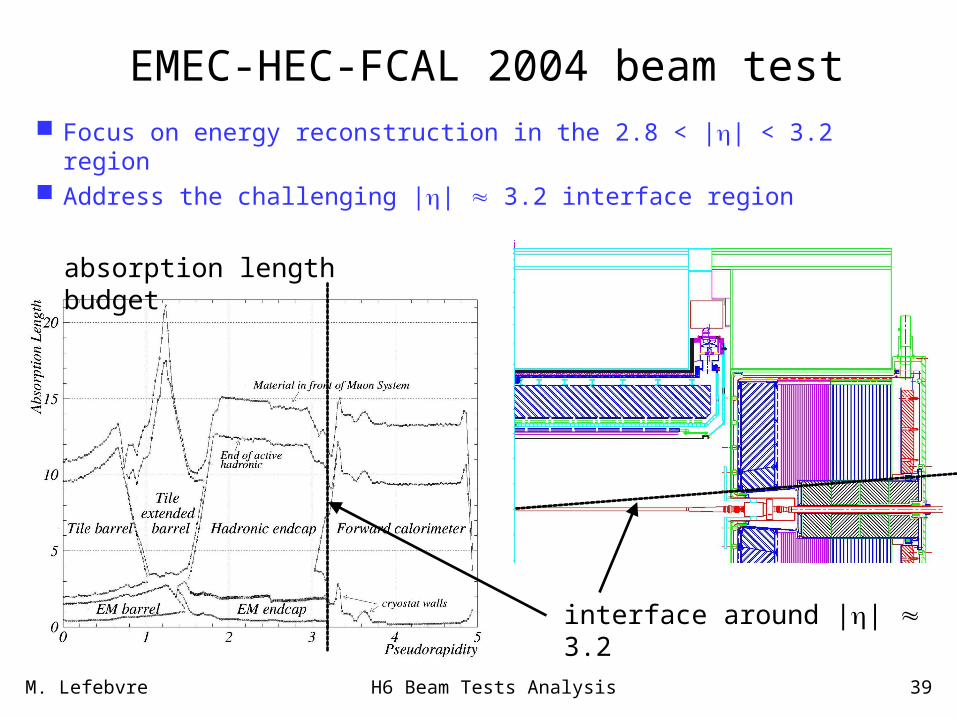
EMEC-HEC-FCAL 2004 beam test
Focus on energy reconstruction in the 2.8 < || < 3.2 region Address the challenging || 3.2 interface region
interface around || 3.2
absorption length budget

M. Lefebvre H6 Beam Tests Analysis 40
EMEC-HEC-FCAL 2004 beam test Space constraints in cryostat
EMEC module0 (refurbished) HEC mini-modules (space constraints in
H1 cryostat) FCal1 module0 (refurbished in Arizona) FCal2 module0 (refurbished in Toronto) Cold Tailcatcher (Cu-LAr parallel plate
technology) instead of FCal3 New warm tailcatcher behind cryostat Mockup of cryostat forward cone and
FCal cold tube

M. Lefebvre H6 Beam Tests Analysis 41
EMEC-HEC-FCAL: beam test setup
Lifting Tool for Complete Setup
Lifting Tool for HEC1 or HEC2
EMEC
FCAL
FCAL Frame

M. Lefebvre H6 Beam Tests Analysis 42
EMEC-HEC-FCAL: beam test setup
M. Lefebvre H6 Beam Tests Analysis 43
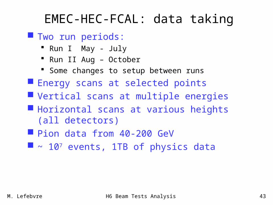
EMEC-HEC-FCAL: data taking Two run periods:
Run I May - July Run II Aug – October Some changes to setup between runs
Energy scans at selected points Vertical scans at multiple energies Horizontal scans at various heights (all detectors) Pion data from 40-200 GeV ~ 107 events, 1TB of physics data
M. Lefebvre H6 Beam Tests Analysis 44
EMEC-HEC-FCAL studies underway
• Continued offline software reconstruction coordination
• Testbeam beam elements fully supported in Athena
• Studies of scintillator pedestals
• Studies of beam selection criteria
• BPC Calibration
• BPC Alignment
• Autocorrelation matrix – in database for Run II
• Pulse Shape Studies
• Calorimeter Noise studies
• OFC determination (awaiting pulse shape from physics data)
• Monte Carlo simulation

M. Lefebvre H6 Beam Tests Analysis 45
EMEC-HEC-FCAL: beam studies
Double hit cutBPC5 time drift during run
XX
YY
Relatively small effect (order 100 μm). Correction in progress

M. Lefebvre H6 Beam Tests Analysis 46
HEC noise:
factor 2-3 too large!
EMEC noise:
typically factor 5
too large!
CTC
2004 EMEC/HEC/FCAL: Noise

M. Lefebvre H6 Beam Tests Analysis 47
EMEC-HEC-FCAL: HEC noise from amplitude and slope
kHzf
ADCA
AAdTdA
dTdA
tAdT
dAtAA
2.10.1632
8.16.360
)min()max(
)min()max(
)cos(
)sin(
0
0
0
Hope: was “one-off” DC-DC Hope: was “one-off” DC-DC converter used only in this TBconverter used only in this TB
Fix for TB : Either measure noise Fix for TB : Either measure noise phase or do event-by-event ped fitphase or do event-by-event ped fit

M. Lefebvre H6 Beam Tests Analysis 48
EMEC-HEC-FCAL TB Monte Carlo Very first (2004/12/08) visualization of 2004 EMEC-
HEC-FCAL TB MC using Athena!
100 GeV pion (charged tracks) in the 2004 EMEC-HEC-FCAL beam test setup

M. Lefebvre H6 Beam Tests Analysis 49
Conclusions Extensive H6 beam test programme
a lot of data collected
Test of electronics calibration method and signal reco optimal filter weights detailed electronic calibration procedure for ADC to nA development of the related software tools
Hopefully robust EM scale established Test of first steps toward an hadronic calibration strategy
cluster and/or cell weighting
GEANT4 simulation of beam test setups recently available in Athena

M. Lefebvre H6 Beam Tests Analysis 50
Critical tasks Persistify 2002 EMEC-HEC data
fill database with noise and autocorrelations for each cell
Consolidate the pulse shape analysis software need a robust OFC producing suite of software demonstrate the usage of the FCal current calibration system
Further develop the reconstruction of “final local energy scale signal” use Athena tools, like cluster split/merge tools produce cell level weights depending on cluster quantities validate with beam test EM clusters and simulation use GEANT4 in Athena; minimize code difference between data
and simulation analyses
Combine effort across all beam tests

M. Lefebvre H6 Beam Tests Analysis 51
Critical tasks Address the challenging detector overlap regions
will require specialized techniques for signal reconstruction
Develop strategies against hardware failures simulation of HV problems, dead cells, etc. use beam test data and simulation develop the related softare asses impact on performace

M. Lefebvre H6 Beam Tests Analysis 52
Data and Corrections Flow
RAW DATARAW DATA
LArDigitLArDigit
5 ADC Time Samples5 ADC Time Samples
LArRawChannelLArRawChannel
Energy [GeV]Energy [GeV]
CaloCellCaloCell
Energy [GeV]Energy [GeV]
CaloClusterCaloClusterEnergy [GeV]Energy [GeV]
CaloClusterCaloClusterCorrected Energy [GeV]Corrected Energy [GeV]
ROD ROD (or emulation)(or emulation)Optimal Filter, linear “ramp”Optimal Filter, linear “ramp”
HV corrections, HV corrections, refined energy scalerefined energy scale
Cluster / Cell Offline compensation weightsCluster / Cell Offline compensation weightsDetector specific (Detector specific () corrections) corrections
CELLCELL
CLUSTERCLUSTER
PARTICLEPARTICLE
CLUSTERING
e / e / JETS, JETS, , , ETMISSETMISS
+ Tracker, chambersParticle ID
USER ANAUSER ANA

M. Lefebvre H6 Beam Tests Analysis 53
Hadronic Calibration Models Model I : Physics object based:
first reconstruct hadronic final state physics objects (jets, missing Et) using calorimeter signals on a fixed (electromagnetic) energy scale (accepting the fact that these are ~30% too low, typically);
then calibrate the jets in situ using physics events a priori using “MC Truth” in simulations for normalization
(presently studied approach in ATLAS)• Model I is currently the most common approach in ATLAS
physics studies. It is somewhat fragile, sensitive to fragmentation modeling, jet finding, etc.
Model II : Detector-based objects reconstruct calorimeter final state objects (clusters) first and
calibrate those using a “local” normalization (reference local deposited energy in calorimeter)
reconstruct physics objects in this space of calibrated calorimeter signals
apply higher level corrections for algorithm inefficiencies determined in situ or a priori, as above
• Model II has been the focus of our testbeam analysis, and we are studying it’s applicability to ATLAS

M. Lefebvre H6 Beam Tests Analysis 54
EMEC-HEC: electrons energy resolutionEMEC EMEC EMEC
reco em em visE E I
reco
reco reco
E a bE E
Note: non-pointing setup!!possibly some dependence, due to variation of sampling fraction and weak dependence of electric field
reco reco noiseE E
impact point J

M. Lefebvre H6 Beam Tests Analysis 55
Dead material in front of the FCal
η=3.2
η=3.7
η=4.9
Want to measure calorimeter resolution with and without “simulated” upstream material: cryostat bulkhead, poly shielding, pumps
Testbeam calibration of FCal particularly important as in-situ calibration very difficult. No tracking in front of the FCal
R (
cm)
z (cm)

M. Lefebvre H6 Beam Tests Analysis 56
FCAL electron event display
FCal1 Single electron 200 GeV/c
M. Lefebvre H6 Beam Tests Analysis 57
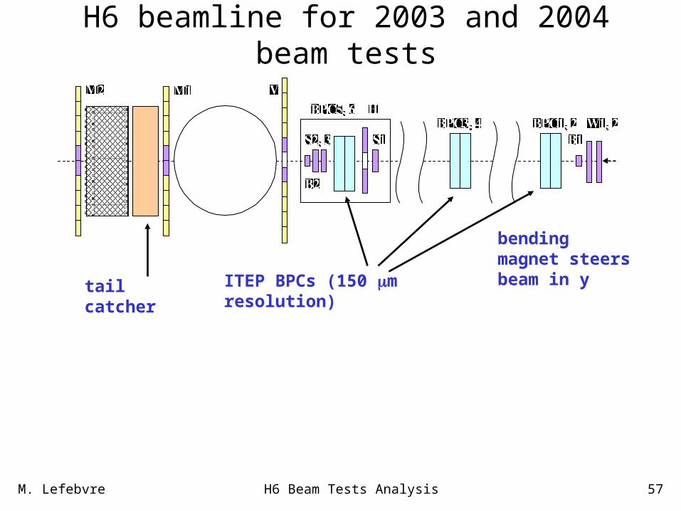
H6 beamline for 2003 and 2004 beam tests
tail catcher
bending magnet steers beam in y
ITEP BPCs (150 m resolution)