Embed Size (px)
Citation preview
H.323 / SIP VoIP Gateway
VIP GW
Quick Installation Guide
OverviewThis quick installation guide describes the objectives; organization and basic installation of the PLANET VIP-281/VIP-480/VIP-880/VIP-1680/VIP-2480 H.323/SIP VoIP Gateway (“VIP-GW” in the following term), and explains how to establish your first voice over IP communication via PLANET product. Also, this guide shows you how to find additional information on related products and services.
The VIP-GW integrates a web-based graphical user interface that can cover most configurations and machine status monitoring. Via standard, web browser, you can configure and check machine status from anywhere around the world.
During this quick installation guide, we will use VIP-GW as the term for this product family. The family products include:
2-Port Model -VIP-281 l equips one FXO and one FXS interfaces to have the great flexibility of PBX connection (FXO), and telephone or FAX machine connection (FXS).
VIP-281FS l equips two FXS interfaces telephone set or FAX machine connection (FXS).
4-Port Model -VIP-480 l equips two FXO and two FXS interfaces to have the great flexibility of PBX connection (FXO), and telephone set or FAX machine connection (FXS).
VIP-480FS l equips four FXS interfaces telephone set or FAX machine connection (FXS).
VIP-480FO l equips four FXO interfaces to have the great flexibility of PBX connection (FXO).
VIP-480FD l equips four FXO interfaces support Caller ID to have the great flexibility of PBX connection (FXO).
8-Port Model - VIP-880 l equips four FXO and four FXS interfaces to have the great flexibility of PBX connection (FXO), and telephone or FAX machine connection (FXS).
VIP-880FO l equips eight FXO interfaces to have the great flexibility of PBX connection (FXO).
16-Port Model - VIP-1680 l equips eight FXO and eight FXS interfaces to have the great flexibility of PBX connection (FXO), and telephone or FAX machine connection (FXS).
VIP-1680FS l equips sixteen FXS interfaces telephone set or FAX machine connection (FXS).
VIP-1680FO l equips sixteen FXO interfaces to have the great flexibility of PBX connection (FXO).
VIP-1680FD l equips sixteen FXO interfaces support Caller ID to have the great flexibility of PBX connection (FXO).
24-Port Model - VIP-2480 l equips twelve FXO and twelve FXS interfaces to have the great flexibility of PBX connection (FXO), and telephone or FAX machine connection (FXS).
VIP-2480FS l equips twenty-four FXS interfaces telephone set or FAX machine connection (FXS).
VIP-2480FO l equips twenty-four FXO interfaces to have the great flexibility of PBX connection (FXO).
VIP-2480FD l equips twenty-four FXO interfaces support Caller ID to have the great flexibility of PBX connection (FXO).
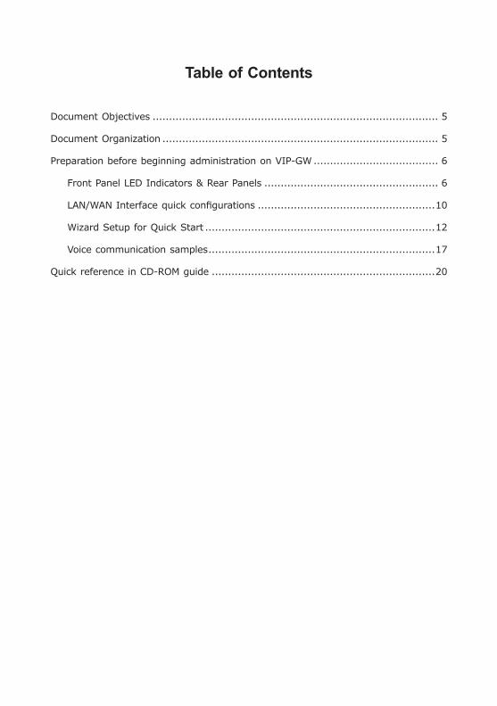
Table of Contents
Document Objectives ....................................................................................... 5
Document Organization .................................................................................... 5
Preparation before beginning administration on VIP-GW ...................................... 6
Front Panel LED Indicators & Rear Panels ..................................................... 6
LAN/WAN Interface quick configurations ......................................................10
Wizard Setup for Quick Start ......................................................................12
Voice communication samples .....................................................................17
Quick reference in CD-ROM guide ....................................................................20
5
Document ObjectivesThis guide provides physical installation, LAN/WAN IP configurations, and Internet access establishment information for the PLANET VIP-281/VIP-480/VIP-880/VIP-1680/VIP-2480 H.323/SIP VoIP Gateway.
Document OrganizationThis guide is organized as follows:
Preparation before beginning administration on VIP-281/VIP-480/VIP-880/ l
VIP-1680/VIP-2480
Administration interface l
LAN/WAN interface quick configurations l
Internet access setup guide l
6
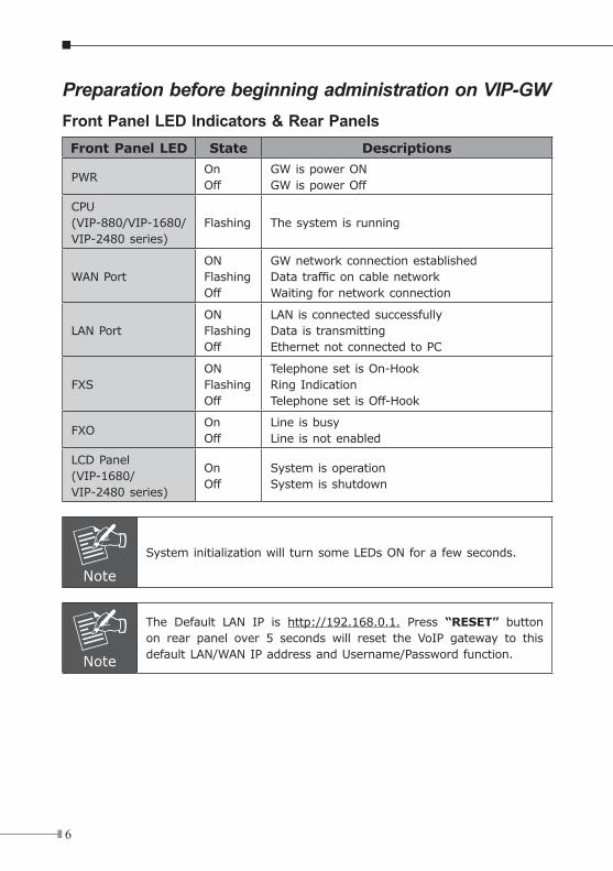
Preparation before beginning administration on VIP-GWFront Panel LED Indicators & Rear PanelsFront Panel LED State Descriptions
PWROnOff
GW is power ON GW is power Off
CPU(VIP-880/VIP-1680/VIP-2480 series)
Flashing The system is running
WAN PortONFlashing Off
GW network connection establishedData traffic on cable networkWaiting for network connection
LAN PortONFlashing Off
LAN is connected successfullyData is transmittingEthernet not connected to PC
FXSONFlashing Off
Telephone set is On-HookRing IndicationTelephone set is Off-Hook
FXOOnOff
Line is busyLine is not enabled
LCD Panel(VIP-1680/VIP-2480 series)
OnOff
System is operationSystem is shutdown
Note
System initialization will turn some LEDs ON for a few seconds.
Note
The Default LAN IP is http://192.168.0.1. Press “RESET” button on rear panel over 5 seconds will reset the VoIP gateway to this default LAN/WAN IP address and Username/Password function.
7
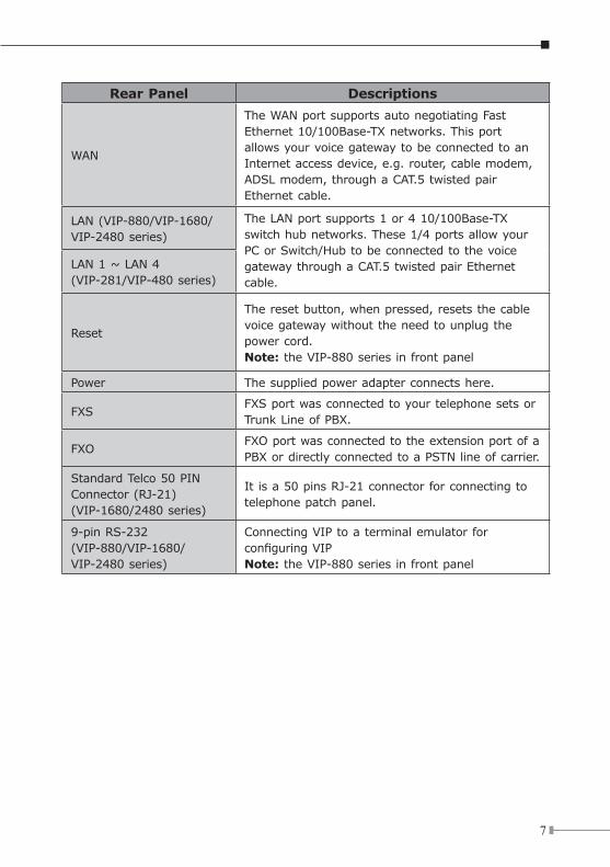
Rear Panel Descriptions
WAN
The WAN port supports auto negotiating Fast Ethernet 10/100Base-TX networks. This port allows your voice gateway to be connected to an Internet access device, e.g. router, cable modem, ADSL modem, through a CAT.5 twisted pair Ethernet cable.
LAN (VIP-880/VIP-1680/VIP-2480 series)
The LAN port supports 1 or 4 10/100Base-TX switch hub networks. These 1/4 ports allow your PC or Switch/Hub to be connected to the voice gateway through a CAT.5 twisted pair Ethernet cable.
LAN 1 ~ LAN 4(VIP-281/VIP-480 series)
Reset
The reset button, when pressed, resets the cable voice gateway without the need to unplug the power cord.Note: the VIP-880 series in front panel
Power The supplied power adapter connects here.
FXSFXS port was connected to your telephone sets or Trunk Line of PBX.
FXOFXO port was connected to the extension port of a PBX or directly connected to a PSTN line of carrier.
Standard Telco 50 PIN Connector (RJ-21)(VIP-1680/2480 series)
It is a 50 pins RJ-21 connector for connecting to telephone patch panel.
9-pin RS-232(VIP-880/VIP-1680/VIP-2480 series)
Connecting VIP to a terminal emulator for configuring VIPNote: the VIP-880 series in front panel
8
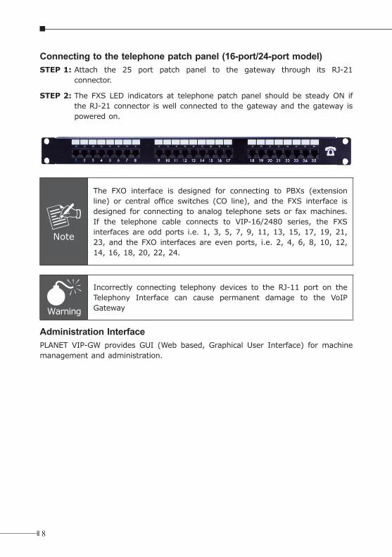
Connecting to the telephone patch panel (16-port/24-port model)STEP 1: Attach the 25 port patch panel to the gateway through its RJ-21
connector.
STEP 2: The FXS LED indicators at telephone patch panel should be steady ON if the RJ-21 connector is well connected to the gateway and the gateway is powered on.
Note
The FXO interface is designed for connecting to PBXs (extension line) or central office switches (CO line), and the FXS interface is designed for connecting to analog telephone sets or fax machines. If the telephone cable connects to VIP-16/2480 series, the FXS interfaces are odd ports i.e. 1, 3, 5, 7, 9, 11, 13, 15, 17, 19, 21, 23, and the FXO interfaces are even ports, i.e. 2, 4, 6, 8, 10, 12, 14, 16, 18, 20, 22, 24.
Warning
Incorrectly connecting telephony devices to the RJ-11 port on the Telephony Interface can cause permanent damage to the VoIP Gateway
Administration InterfacePLANET VIP-GW provides GUI (Web based, Graphical User Interface) for machine management and administration.
9
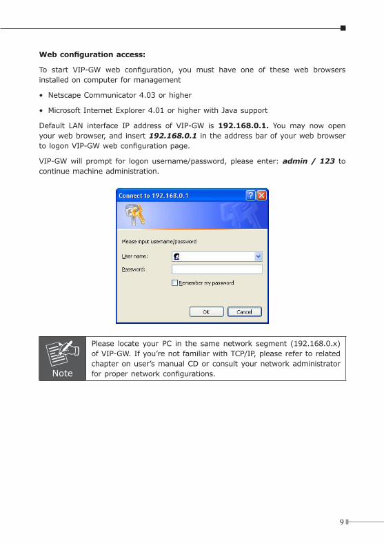
Web configuration access:
To start VIP-GW web configuration, you must have one of these web browsers installed on computer for management
• Netscape Communicator 4.03 or higher
• Microsoft Internet Explorer 4.01 or higher with Java support
Default LAN interface IP address of VIP-GW is 192.168.0.1. You may now open your web browser, and insert 192.168.0.1 in the address bar of your web browser to logon VIP-GW web configuration page.
VIP-GW will prompt for logon username/password, please enter: admin / 123 to continue machine administration.
Note
Please locate your PC in the same network segment (192.168.0.x) of VIP-GW. If you’re not familiar with TCP/IP, please refer to related chapter on user’s manual CD or consult your network administrator for proper network configurations.
10
LAN/WAN Interface quick configurationsNature of PLANET VIP-GW is an IP Sharing (NAT) device, it comes with two default IP addresses, and default LAN side IP address is “192.168.0.1”, default WAN side IP address is “172.16.0.1”. You may use any PC to connect to the LAN port of VIP-GW to start machine administration.
Hint
In general cases, the LAN IP address is the default gateway of LAN side workstations for Internet access, and the WAN IP of VIP-GW are the IP address for remote calling party to connect with.
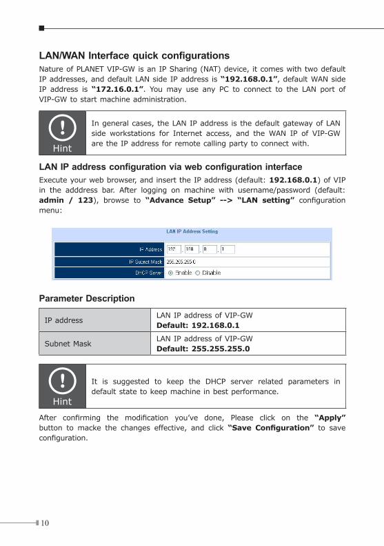
LAN IP address configuration via web configuration interfaceExecute your web browser, and insert the IP address (default: 192.168.0.1) of VIP in the adddress bar. After logging on machine with username/password (default: admin / 123), browse to “Advance Setup” --> “LAN setting” configuration menu:
Parameter Description
IP address LAN IP address of VIP-GWDefault: 192.168.0.1
Subnet MaskLAN IP address of VIP-GWDefault: 255.255.255.0
Hint
It is suggested to keep the DHCP server related parameters in default state to keep machine in best performance.
After confirming the modification you’ve done, Please click on the “Apply” button to macke the changes effective, and click “Save Configuration” to save configuration.
11
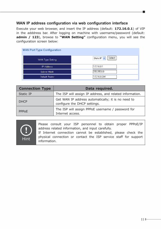
WAN IP address configuration via web configuration interfaceExecute your web browser, and insert the IP address (default: 172.16.0.1) of VIP in the adddress bar. After logging on machine with username/password (default: admin / 123), browse to “WAN Setting” configuration menu, you will see the configuration screen below:
Connection Type Data required.
Static IP The ISP will assign IP address, and related information.
DHCPGet WAN IP address automatically; it is no need to configure the DHCP settings.
PPPoEThe ISP will assign PPPoE username / password for Internet access.
Hint
Please consult your ISP personnel to obtain proper PPPoE/IP address related information, and input carefully. If Internet connection cannot be established, please check the physical connection or contact the ISP service staff for support information.
12
Wizard Setup for Quick StartWizard Setup
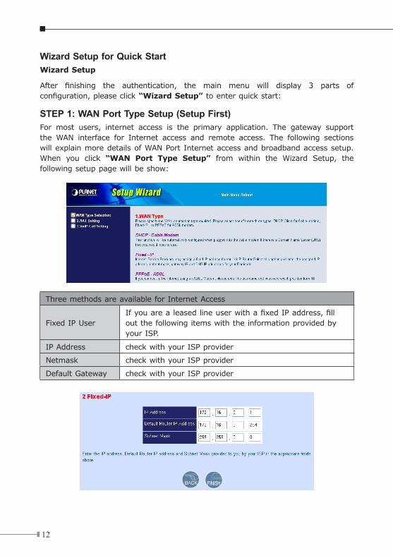
After finishing the authentication, the main menu will display 3 parts of configuration, please click “Wizard Setup” to enter quick start:
STEP 1: WAN Port Type Setup (Setup First)For most users, internet access is the primary application. The gateway support the WAN interface for Internet access and remote access. The following sections will explain more details of WAN Port Internet access and broadband access setup. When you click “WAN Port Type Setup” from within the Wizard Setup, the following setup page will be show:
Three methods are available for Internet Access
Fixed IP UserIf you are a leased line user with a fixed IP address, fill out the following items with the information provided by your ISP.
IP Address check with your ISP provider
Netmask check with your ISP provider
Default Gateway check with your ISP provider
13
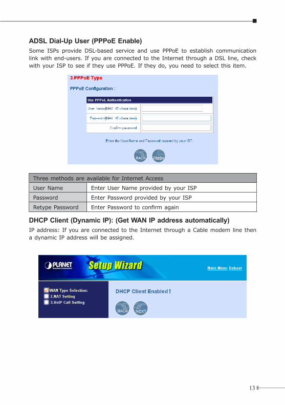
ADSL Dial-Up User (PPPoE Enable) Some ISPs provide DSL-based service and use PPPoE to establish communication link with end-users. If you are connected to the Internet through a DSL line, check with your ISP to see if they use PPPoE. If they do, you need to select this item.
Three methods are available for Internet Access
User Name Enter User Name provided by your ISP
Password Enter Password provided by your ISP
Retype Password Enter Password to confirm again
DHCP Client (Dynamic IP): (Get WAN IP address automatically) IP address: If you are connected to the Internet through a Cable modem line then a dynamic IP address will be assigned.
14
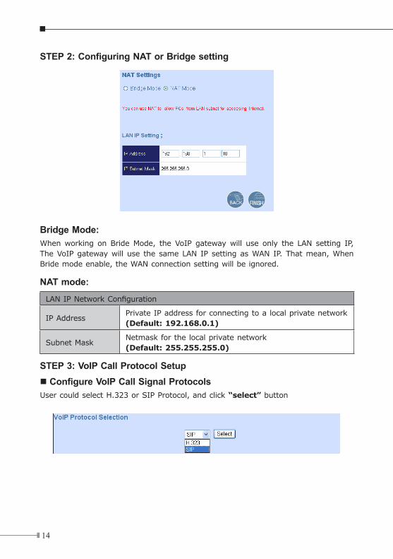
STEP 2: Configuring NAT or Bridge setting
Bridge Mode:When working on Bride Mode, the VoIP gateway will use only the LAN setting IP, The VoIP gateway will use the same LAN IP setting as WAN IP. That mean, When Bride mode enable, the WAN connection setting will be ignored.
NAT mode:
LAN IP Network Configuration
IP AddressPrivate IP address for connecting to a local private network (Default: 192.168.0.1)
Subnet MaskNetmask for the local private network(Default: 255.255.255.0)
STEP 3: VoIP Call Protocol Setupn Configure VoIP Call Signal ProtocolsUser could select H.323 or SIP Protocol, and click “select” button
15
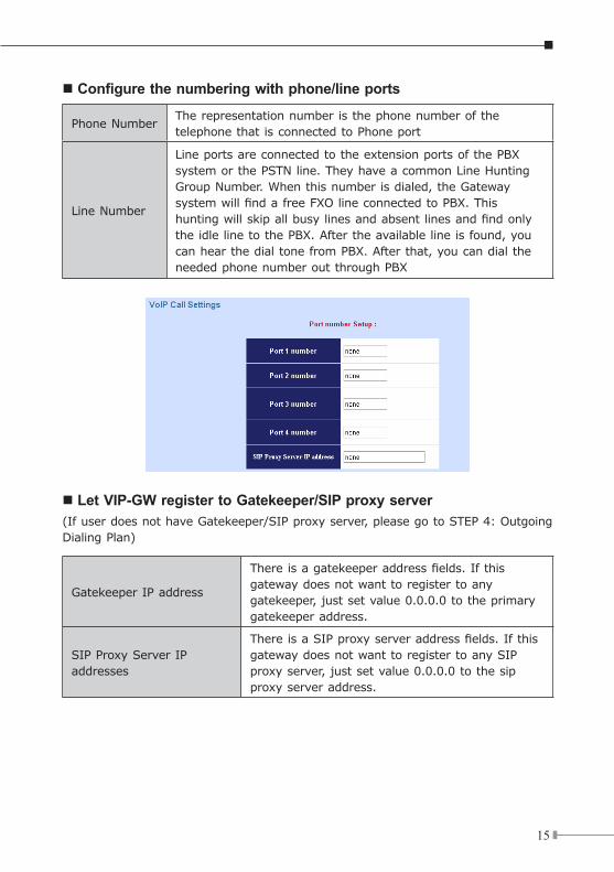
n Configure the numbering with phone/line ports
Phone NumberThe representation number is the phone number of the telephone that is connected to Phone port
Line Number
Line ports are connected to the extension ports of the PBX system or the PSTN line. They have a common Line Hunting Group Number. When this number is dialed, the Gateway system will find a free FXO line connected to PBX. This hunting will skip all busy lines and absent lines and find only the idle line to the PBX. After the available line is found, you can hear the dial tone from PBX. After that, you can dial the needed phone number out through PBX
n Let VIP-GW register to Gatekeeper/SIP proxy server(If user does not have Gatekeeper/SIP proxy server, please go to STEP 4: Outgoing Dialing Plan)
Gatekeeper IP address
There is a gatekeeper address fields. If this gateway does not want to register to any gatekeeper, just set value 0.0.0.0 to the primary gatekeeper address.
SIP Proxy Server IP addresses
There is a SIP proxy server address fields. If this gateway does not want to register to any SIP proxy server, just set value 0.0.0.0 to the sip proxy server address.
16
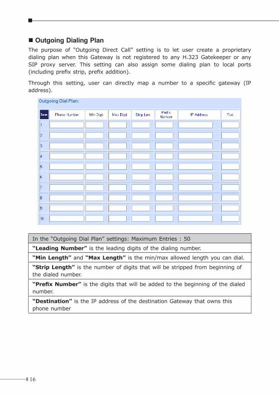
n Outgoing Dialing Plan The purpose of “Outgoing Direct Call” setting is to let user create a proprietary dialing plan when this Gateway is not registered to any H.323 Gatekeeper or any SIP proxy server. This setting can also assign some dialing plan to local ports (including prefix strip, prefix addition).
Through this setting, user can directly map a number to a specific gateway (IP address).
In the “Outgoing Dial Plan” settings: Maximum Entries : 50
“Leading Number” is the leading digits of the dialing number.
“Min Length” and “Max Length” is the min/max allowed length you can dial.
“Strip Length” is the number of digits that will be stripped from beginning of the dialed number.
“Prefix Number” is the digits that will be added to the beginning of the dialed number.
“Destination” is the IP address of the destination Gateway that owns this phone number
17
n Finishing the Wizard Setup After completing the Wizard Setup, please click “Finish” bottom. The VoIP gateway will save the configuration and rebooting gateway automatically. After 20 Seconds, you could re-login the gateway.
Voice communication samplesThe chapter shows you the concept and command to help you configure your VoIP gateway through sample configuration. And provide several ways to make calls to desired destination in VIP-GW. In this section, we’ll lead you step by step to establish your first voice communication via web browsers operations.
Concepts: Voice PortThere are two type of the voice port, FXO (Foreign exchange Office) and FXS. (Foreign exchange Station) On the printing of the RJ-11 port, you should find that.
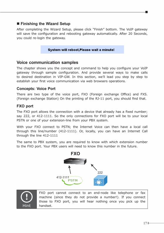
FXO portThe FXO port allows the connection with a device that already has a fixed number; say 222, or 412-1111. So the only connections for FXO port will be to your local PSTN or one of your extension-line from your PBX system.
With your FXO connect to PSTN; the Internet Voice can then have a local call through this line/number (412-1111). Or, locally, you can have an Internet Call through the line 412-1111
The same to PBX system, you are required to know with which extension number to the FXO port. Your PBX users will need to know this number in the future.
PSTN412-1111
222
FXO
412-1111222
FXS
WAN
Gateway#1 Gateway#2
100 100
Phone Phone
8100
9100
Gateway#1 Gateway#2
901 801Phone Phone
801
901
Registration /Authentication
Registration /Authentication
WAN
SIP IP PBX (172.16.0.3)IPX-300
Hint
FXO port cannot connect to an end-node like telephone or fax machine (since they do not provide a number!). If you connect those to FXO port, you will hear nothing once you pick up the handset.
18
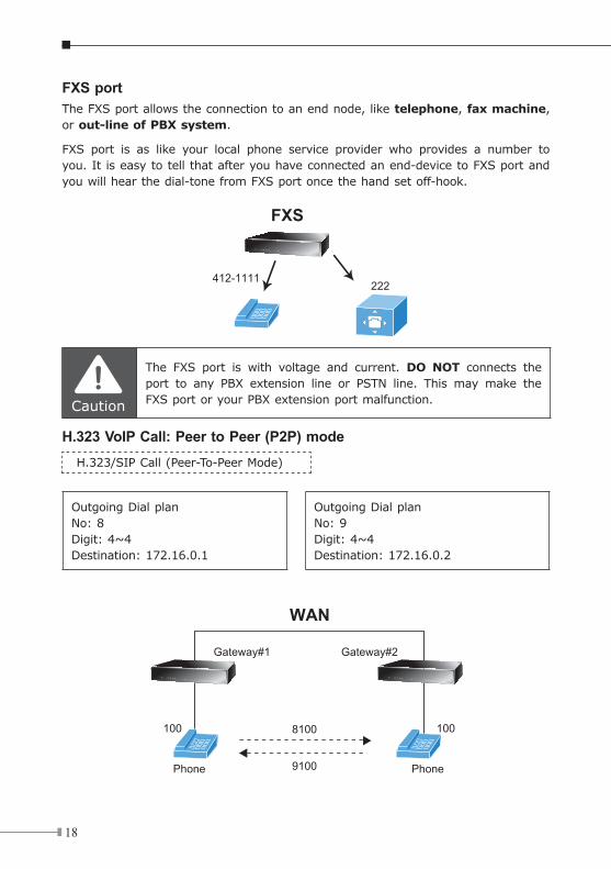
FXS portThe FXS port allows the connection to an end node, like telephone, fax machine, or out-line of PBX system.
FXS port is as like your local phone service provider who provides a number to you. It is easy to tell that after you have connected an end-device to FXS port and you will hear the dial-tone from FXS port once the hand set off-hook.
PSTN412-1111
222
FXO
412-1111222
FXS
WAN
Gateway#1 Gateway#2
100 100
Phone Phone
8100
9100
Gateway#1 Gateway#2
901 801Phone Phone
801
901
Registration /Authentication
Registration /Authentication
WAN
SIP IP PBX (172.16.0.3)IPX-300
Caution
The FXS port is with voltage and current. DO NOT connects the port to any PBX extension line or PSTN line. This may make the FXS port or your PBX extension port malfunction.
H.323 VoIP Call: Peer to Peer (P2P) mode H.323/SIP Call (Peer-To-Peer Mode)
Outgoing Dial planNo: 8Digit: 4~4Destination: 172.16.0.1
Outgoing Dial planNo: 9Digit: 4~4Destination: 172.16.0.2
PSTN412-1111
222
FXO
412-1111222
FXS
WAN
Gateway#1 Gateway#2
100 100
Phone Phone
8100
9100
Gateway#1 Gateway#2
901 801Phone Phone
801
901
Registration /Authentication
Registration /Authentication
WAN
SIP IP PBX (172.16.0.3)IPX-300
19
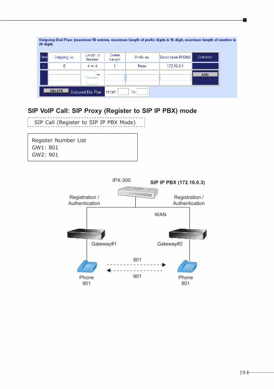
SIP VoIP Call: SIP Proxy (Register to SIP IP PBX) modeSIP Call (Register to SIP IP PBX Mode)
Register Number ListGW1: 801GW2: 901
PSTN412-1111
222
FXO
412-1111222
FXS
WAN
Gateway#1 Gateway#2
100 100
Phone Phone
8100
9100
Gateway#1 Gateway#2
901 801Phone Phone
801
901
Registration /Authentication
Registration /Authentication
WAN
SIP IP PBX (172.16.0.3)IPX-300
20
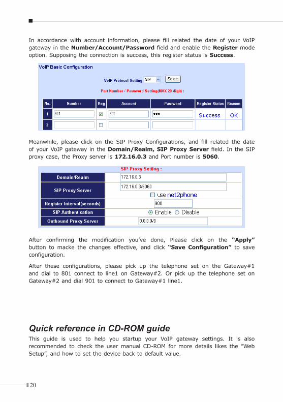
In accordance with account information, please fill related the date of your VoIP gateway in the Number/Account/Password field and enable the Register mode option. Supposing the connection is success, this register status is Success.
Meanwhile, please click on the SIP Proxy Configurations, and fill related the date of your VoIP gateway in the Domain/Realm, SIP Proxy Server field. In the SIP proxy case, the Proxy server is 172.16.0.3 and Port number is 5060.
After confirming the modification you’ve done, Please click on the “Apply” button to macke the changes effective, and click “Save Configuration” to save configuration.
After these configurations, please pick up the telephone set on the Gateway#1 and dial to 801 connect to line1 on Gateway#2. Or pick up the telephone set on Gateway#2 and dial 901 to connect to Gateway#1 line1.
Quick reference in CD-ROM guideThis guide is used to help you startup your VoIP gateway settings. It is also recommended to check the user manual CD-ROM for more details likes the “Web Setup”, and how to set the device back to default value.