Embed Size (px)
Citation preview
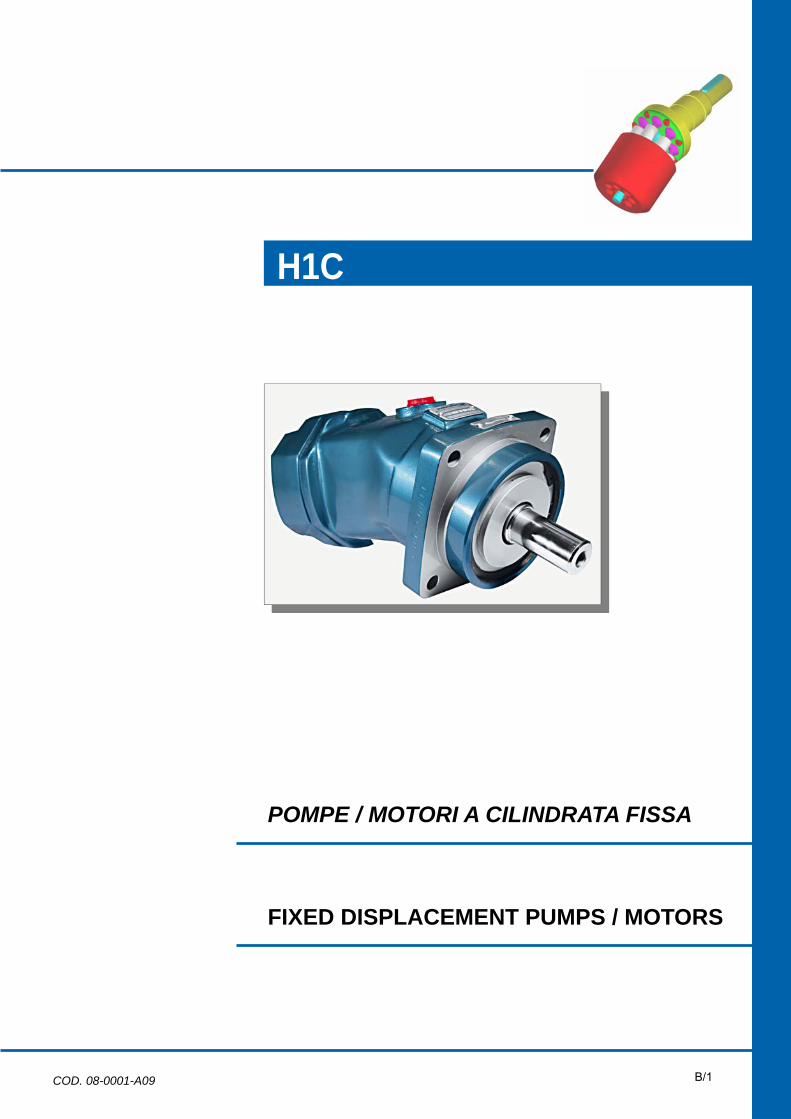
POMPE / MOTORI A CILINDRATA FISSA
H1C
FIXED DISPLACEMENT PUMPS / MOTORS
COD. 08-0001-A09 B/1

INDICE / INDEX
DESCRIZIONE CARATTERISTICHE - DESCRIPTION FEATURES Pag. B/4
CARATTERISTICHE TECNICHE - TECHNICAL SPECIFICATIONS Pag. B/5
DATI TECNICI - TECHNICAL DATA Pag. B/7
CODICE DI ORDINAZIONE - ORDERING CODE Pag. B/9
DIMENSIONALI - DIMENSIONALS Pag. B/13
VERSIONI SPECIALI - SPECIAL VERSIONS Pag. B/33
B/4
axial piston
R
axial pistonaxial piston
R
DESCRIZIONE - CARATTERISTICHE GENERAL INFORMATION - FEATURES
Le unità della serie H1C sono una famiglia di pompe e motori a pistoni assiali, a corpo inclinato, a cilindrata fissa, progettati per operare sia in circuito chiuso che in circuito aperto. Il distributore a superficie sferica, l'accurata lavorazione e l'alta qualità dei materiali e dei componenti usati, consentono ai motori della serie H1C di lavorare fino a 350 bar in continuo e di sopportare picchi di 450 bar. Provati in laboratorio e sperimentati sul campo queste unità hanno dimostrato una lunga durata di esercizio con elevati rendimenti. Il supporto dell'albero, realizzato mediante cuscinetti a rotolamento, è dimensionato in modo da sopportare elevati carichi assiali e radiali. La versatilità delle serie H1C, comprendente vari coperchi, alberi di uscita e valvole flangiabili, consente a queste unità di adattarsi alle più diverse tipologie di impianto, sia nel settore mobile che in quello industriale. Le unità a pistoni H1C sono disponibili in versione ISO e in versione SAE.
H1C series units are a family of fixed displacement pumps and motors, bent axis piston design for operation in both open and closed circuit. The proven design incorporating the lens shape valve plate, the high quality components and manufacturing techniques make the H1C series units to able provide up to 350 bar [5100 psi] continuous and 450 bar [6500 psi] peak performance. Fully laboratory tested and field proven, these units provide maximum efficiency and longlife. Heavy duty bearings permit high radial and axial loads. Versatile design includes a variety of port plate, shaft end and valves package that will adapt the H1C series units to any application both industrial and mobile. H1C series units are available in both ISO and SAE version.
B/5
axial piston
R
axial pistonaxial piston
R
CARATTERISTICHE TECNICHE TECHNICAL SPECIFICATIONS
Albero di uscita: L'albero di uscita è in grado di sopportare sia carichi radiali sia assiali. Per i valori ammissibili dei carichi applicabili consultare nel Catalogo Informazioni Generali, la sezione “Durata dei cuscinetti delle unità a pistoni assiali”.
Output shaft: Main shaft has bearings that can bear both radial and axial loads. As for loads permissible values, see on the General Information Catalogue, the section “Service life of bearings for axial piston units”.
Fluidi: Utilizzare fluidi a base minerale con additivi anticorrosione, antiossidanti e antiusura (HL o HM) con viscosità alla temperatura di esercizio di 15 ÷40 cSt. Una viscosità limite di 800 cSt è ammissibile solo per brevi periodi in Condizione di partenza a freddo. Non sono ammesse viscosità inferiori ai 10 cSt. Viscosità comprese tra i 10 e i 15 cSt sono tollerate solo in casi eccezionali e per brevi periodi. Per maggiori dettagli consultare nel Catalogo Informazioni Generali la sezione “Fluidi e filtrazione”.
Hydraulic fluids: Use fluids with mineral oil basis and anticorrosive, antioxidant and wear preventing addition agents (HL or HM). Viscosity range at operating temperature must be of 15 ÷40 cSt. For short periods and upon cold start, a max. viscosity of 800 cSt is allowed. Viscosities less then 10 cSt are not allowed. A viscosity range of 10 ÷ 15 cSt is allowed for extreme operating conditions and for short periods only. For further information see on the General Information Catalogue, the section “Fluids and filtering”.
Temperature: Non è ammesso il funzionamento dell'unità a pistoni con temperature del fluido idraulico superiori a 90ºC e inferiori a -25ºC. Per maggiori dettagli consultare la sezione Fluidi e filtrazione.
Temperature ranges: The operating temperature of the oil must be within -25ºC÷ 90ºC [-13ºF ÷ 194ºF]. The running of the axial piston unit with oil temperature higher than 90ºC [194°F] or lower than -25ºC [-13°F] is not allowed. For further information see at Fluids and filtering section.
Filtrazione: Una corretta filtrazione contribuisce a prolungare la durata in esercizio dell'unità a pistoni. Per un corretto impiego dell'unità a pistoni la classe di contaminazione massima ammessa è 21/19/16 secondo la ISO 4406:1999. Per maggiori dettagli consultare nel Catalogo Informazioni Generali la sezione “Fluidi e filtrazione”.
Filtering: A correct filtering is essential for long and satisfactory life of axial piston units. In order to ensure a correct functioning of the unit, the max. permissible contamination class is 21/19/16 according to ISO 4406:1999. For further details see on the General Information Catalogue, the section “Fluids and filtering”.
Pressione di alimentazione: (Pompe in circuito aperto) La pressione minima sulla bocca di aspirazione e di 0.8 bar assoluti. La pressione sulla bocca di aspirazione non deve mai scendere al di sotto di tale valore.
Inlet pressure: (Pumps in open circuit) Minimum absolute pressure at suction port is 0.8 bar [11.6 psi]. In no circumstances can inlet pressure be lower.
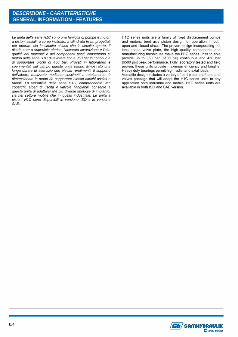
Pressione di esercizio: La pressione massima ammissibile sulle bocche in pressione è 350 bar continui e 450 bar di picco. Nel caso di due motori collegati in serie limitare la pressione di esercizio ai seguenti valori: P1 400 bar massimi e P2 200 bar massimi.
Operating pressure: The maximum permissible pressure on pressure ports is 350 bar [5100 psi] continuous and 450 bar [6500 psi] peak. If two motors are connected in series, working pressure has to be limited to following values: P1 400 bar max. [5800 psi] and P2 200 bar max. [2900 psi].
Pressione in carcassa: La pressione massima ammissibile in carcassa è di 1.5 bar. Una pressione superiore può compromettere la durata e la funzionalità della guarnizione dell'albero di uscita.
Case drain pressure: Maximum permissible case drain pressure is 1.5 bar [22 psi]. A higher pressure can affect the main shaft seal or reduce its life.
Guarnizioni: Le guarnizioni utilizzate sulle unità a pistoni assiali H1C standard sono in NBR (Acrylonitrile-Butadiene Elastomer). Per impieghi particolari (alte temperature e fluidi corrosivi) è possibile ordinare l'unità a pistoni con guarnizioni in FKM (Fluoroelastomer). Nel caso di impiego di fluidi speciali contattare la S.A.M. Hydraulik S.p.A.
Seals: Seals used on standard H1C series axial piston pumps/motors are of NBR (Acrylonitrile-Butadiene Elastomer). For special uses (high temperatures or corrosive fluids) it is possible to order the unit with FKM seals (Fluoroelastomer). In case of use of special fluids, contact S.A.M. Hydraulik S.p.A.
B/6
axial piston
R
axial pistonaxial piston
R
Regime minimo di rotazione: Con regime minimo di rotazione si intende la velocità minima alla quale l'unità a pistoni può ruotare in assenza di sensibili irregolarità di funzionamento. La regolarità di funzionamento a bassi regimi di rotazione è influenzata da numerosi fattori tra cui il tipo di carico applicato e la pressione di funzionamento. Per velocità di rotazione superiori ai 150 rpm la regolarità di funzionamento è assicurata quasi nella totalità dei casi. Velocità inferiori sono generalmente possibili. Per casi particolari contattare la S.A.M. Hydraulik S.p.A.
Minimum rotating speed: Minimum rotating speed is the minimum speed ensuring a smooth running of the piston unit. Operation smooth at low speeds depends on many factors, as type of load and operating pressure. At a speed higher than 150 rpm, a smooth running is ensured almost in every case. Lower speeds are, usually, possible. Please contact S.A.M. Hydraulik S.p.A. .
Installazione: Le pompe e i motori possono essere installati in qualsiasi direzione e posizione. Queste unità a pistoni hanno le bocche separate dalla carcassa e devono essere obbligatoriamente drenate. Nel caso delle pompe l'installazione con albero verticale e al di sopra del serbatoio comporta alcune limitazioni. Per maggiori dettagli consultare nel Catalogo Informazioni Generali la sezione “Norme generali di installazione”.
Installation: H1C series pumps and motors can be installed in every position or direction. These axial piston units have separate ports and drain chambers and so must be always drained. As for pumps, installation of the unit with shaft in vertical position and above the tank involves some limitations. For further details see on the General Information Catalogue, the section “General installation guidelines”.
Valvole flangiabili: Le valvole sono disponibili per i motori sia in circuito aperto sia chiuso. Per maggiori dettagli consultare il Catalogo Valvole.
Flangeable valves: Flangeable valves are available for motors both in open and closed loop. For further details see at Valves Catalogue.
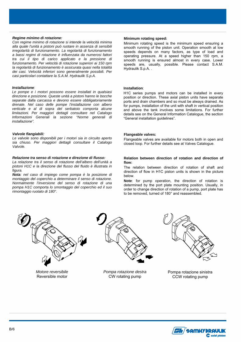
Relation between direction of rotation and direction of flow: The relation between direction of rotation of shaft and direction of flow in H1C piston units is shown in the picture below. Note: for pump operation, the direction of rotation is determined by the port plate mounting position. Usually, in order to change direction of rotation of a pump, port plate has to be removed, turned of 180° and reassembled.
Relazione tra senso di rotazione e direzione di flusso: La relazione tra il senso di rotazione dell’albero dell’unità a pistoni H1C e la direzione del flusso del fluido è illustrata in figura. Nota: nel caso di impiego come pompa è la posizione di montaggio del coperchio a determinare il senso di rotazione. Normalmente l’inversione del senso di rotazione di una pompa H1C comporta lo smontaggio del coperchio ed il suo rimontaggio ruotato di 180°.
Motore reversibile Reversible motor
Pompa rotazione destra CW rotating pump
Pompa rotazione sinistra CCW rotating pump
B/7
axial piston
R
axial pistonaxial piston
R
DATI TECNICI TECHNICAL DATA
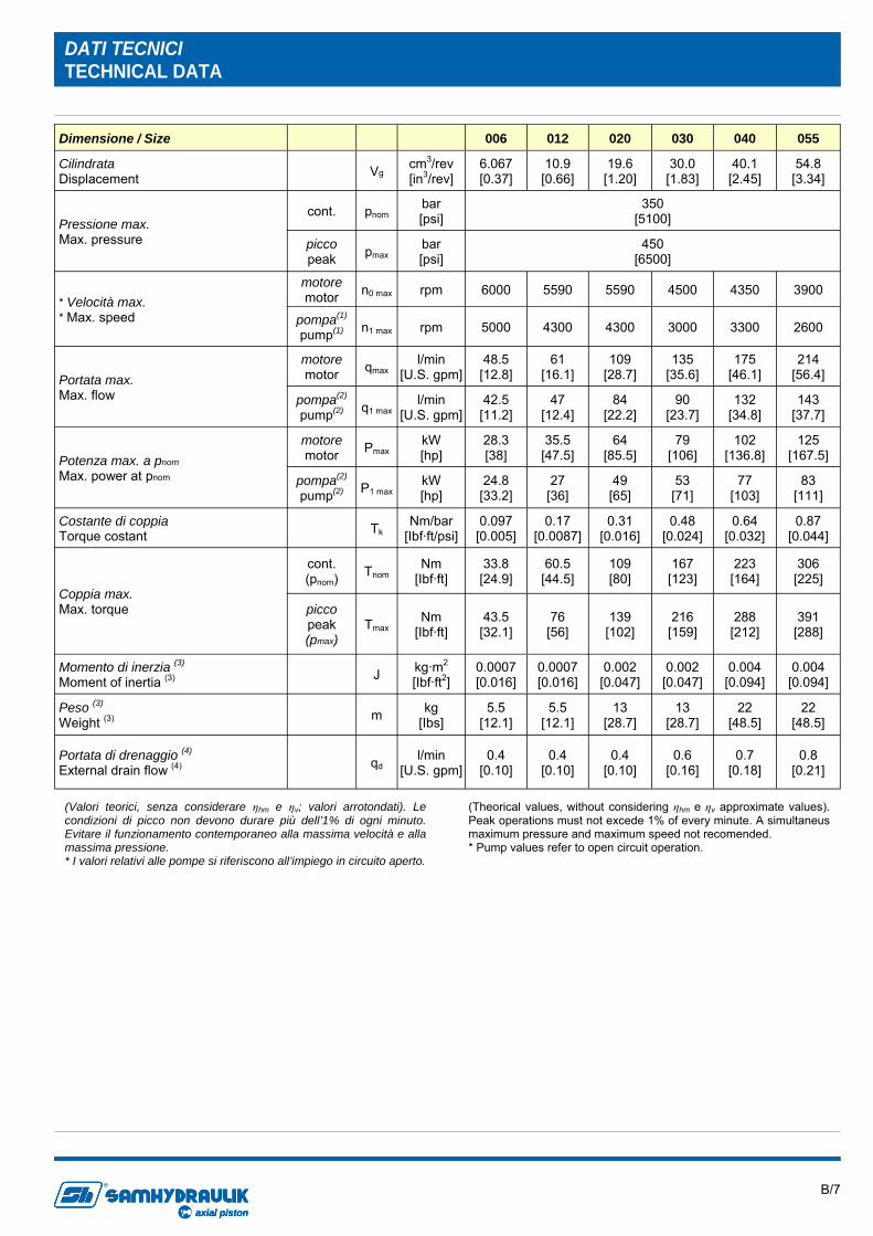
Dimensione / Size 012 020 030 040 055
Cilindrata Displacement Vg
cm3/rev [in3/rev]
10.9 [0.66]
19.6 [1.20]
30.0 [1.83]
40.1 [2.45]
54.8 [3.34]
Pressione max. Max. pressure
cont. pnom bar [psi]
350 [5100]
picco peak pmax
bar [psi]
450 [6500]
* Velocità max. * Max. speed
motore motor n0 max rpm 5590 5590 4500 4350 3900
pompa(1)
pump(1)
n1 max rpm 4300 4300 3000 3300 2600
Portata max. Max. flow
motore motor qmax
l/min [U.S. gpm]
61 [16.1]
109 [28.7]
135 [35.6]
175 [46.1]
214 [56.4]
pompa(2)
pump(2) q1 max l/min
[U.S. gpm] 47
[12.4] 84
[22.2] 90
[23.7] 132
[34.8] 143
[37.7]
Potenza max. a pnom
Max. power at pnom
motore motor Pmax
kW [hp]
35.5 [47.5]
64 [85.5]
79 [106]
102 [136.8]
125 [167.5]
pompa(2) pump(2) P1 max
kW [hp]
27 [36]
49 [65]
53 [71]
77 [103]
83 [111]
Costante di coppia Torque costant Tk
Nm/bar [Ibf·ft/psi]
0.17 [0.0087]
0.31 [0.016]
0.48 [0.024]
0.64 [0.032]
0.87 [0.044]
Coppia max. Max. torque
cont. (pnom) Tnom
Nm [Ibf·ft]
60.5 [44.5]
109 [80]
167 [123]
223 [164]
306 [225]
picco peak (pmax)
Tmax Nm
[Ibf·ft] 76
[56] 139
[102] 216
[159] 288
[212] 391
[288]
Momento di inerzia (3)
Moment of inertia (3)
J kg·m2
[Ibf·ft2] 0.0007 [0.016]
0.002 [0.047]
0.002 [0.047]
0.004 [0.094]
0.004 [0.094]
Peso (3)
Weight (3) m kg [Ibs]
5.5 [12.1]
13 [28.7]
13 [28.7]
22 [48.5]
22 [48.5]
Portata di drenaggio (4)
External drain flow (4) qd l/min
[U.S. gpm] 0.4
[0.10] 0.4
[0.10] 0.6
[0.16] 0.7
[0.18] 0.8
[0.21]
006
6.067 [0.37]
6000
5000
48.5 [12.8]
42.5 [11.2]
28.3 [38]
24.8 [33.2]
0.097 [0.005]
33.8 [24.9]
43.5 [32.1]
0.0007 [0.016]
5.5 [12.1]
0.4 [0.10]
(Valori teorici, senza considerare ηhm e ηv; valori arrotondati). Le condizioni di picco non devono durare più dell’1% di ogni minuto. Evitare il funzionamento contemporaneo alla massima velocità e alla massima pressione. * I valori relativi alle pompe si riferiscono all’impiego in circuito aperto.
(Theorical values, without considering ηhm e ηv approximate values). Peak operations must not excede 1% of every minute. A simultaneus maximum pressure and maximum speed not recomended. * Pump values refer to open circuit operation.
B/8
axial piston
R
axial pistonaxial piston
R
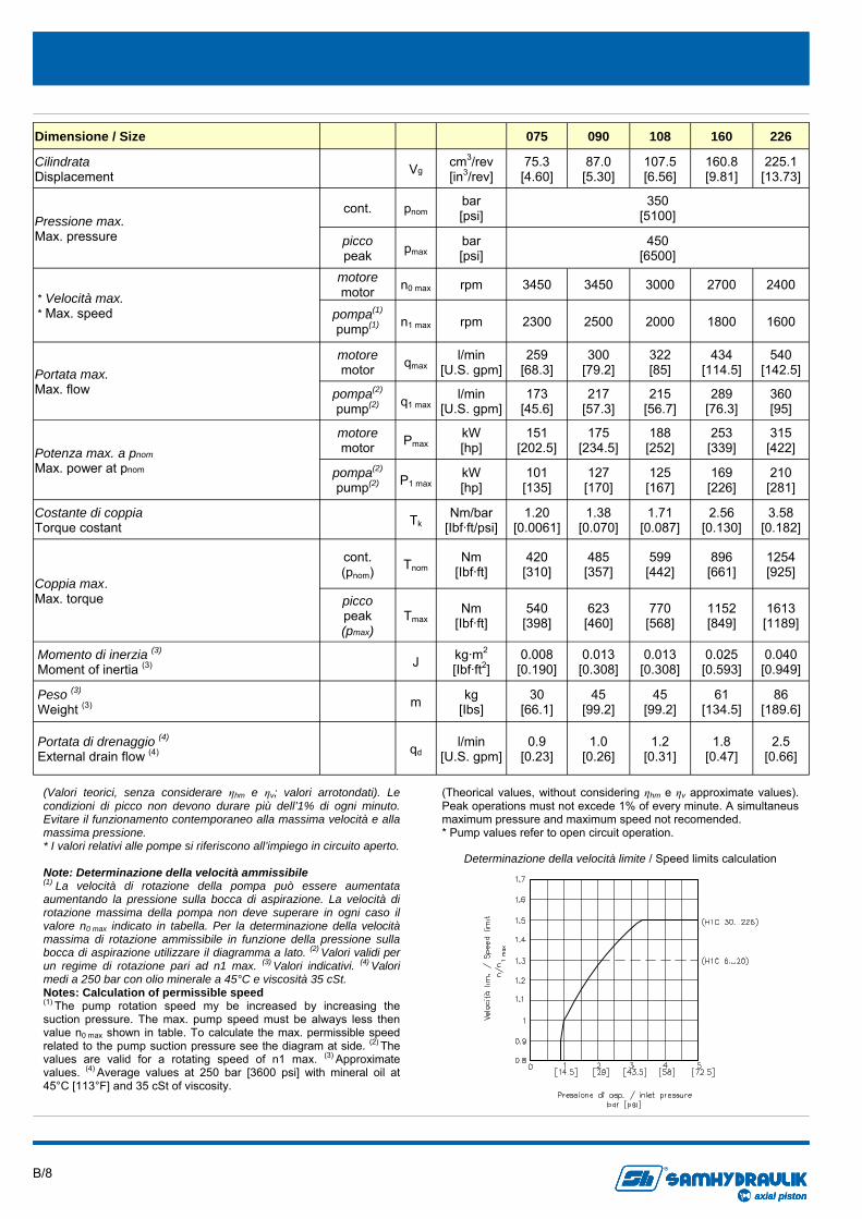
Dimensione / Size 075 090 108 160 226
Cilindrata Displacement Vg
cm3/rev [in3/rev]
75.3 [4.60]
87.0 [5.30]
107.5 [6.56]
160.8 [9.81]
225.1 [13.73]
Pressione max. Max. pressure
cont. pnom bar [psi]
350 [5100]
picco peak pmax
bar [psi]
450 [6500]
* Velocità max. * Max. speed
motore motor n0 max rpm 3450 3450 3000 2700 2400
pompa(1)
pump(1)
n1 max rpm 2300 2500 2000 1800 1600
Portata max. Max. flow
motore motor qmax
l/min [U.S. gpm]
259 [68.3]
300 [79.2]
322 [85]
434 [114.5]
540 [142.5]
pompa(2)
pump(2) q1 max l/min
[U.S. gpm] 173
[45.6] 217
[57.3] 215
[56.7] 289
[76.3] 360 [95]
Potenza max. a pnom
Max. power at pnom
motore motor Pmax
kW [hp]
151 [202.5]
175 [234.5]
188 [252]
253 [339]
315 [422]
pompa(2) pump(2) P1 max
kW [hp]
101 [135]
127 [170]
125 [167]
169 [226]
210 [281]
Costante di coppia Torque costant Tk
Nm/bar [Ibf·ft/psi]
1.20 [0.0061]
1.38 [0.070]
1.71 [0.087]
2.56 [0.130]
3.58 [0.182]
Coppia max. Max. torque
cont. (pnom) Tnom
Nm [Ibf·ft]
420 [310]
485 [357]
599 [442]
896 [661]
1254 [925]
picco peak (pmax)
Tmax Nm
[Ibf·ft] 540
[398] 623
[460] 770
[568] 1152 [849]
1613 [1189]
Momento di inerzia (3)
Moment of inertia (3)
J kg·m2
[Ibf·ft2] 0.008
[0.190] 0.013
[0.308] 0.013
[0.308] 0.025
[0.593] 0.040
[0.949]
Peso (3)
Weight (3) m kg [Ibs]
30 [66.1]
45 [99.2]
45 [99.2]
61 [134.5]
86 [189.6]
Portata di drenaggio (4)
External drain flow (4) qd l/min
[U.S. gpm] 0.9
[0.23] 1.0
[0.26] 1.2
[0.31] 1.8
[0.47] 2.5
[0.66]
(Valori teorici, senza considerare ηhm e ηv; valori arrotondati). Le condizioni di picco non devono durare più dell’1% di ogni minuto. Evitare il funzionamento contemporaneo alla massima velocità e alla massima pressione. * I valori relativi alle pompe si riferiscono all’impiego in circuito aperto. Note: Determinazione della velocità ammissibile (1) La velocità di rotazione della pompa può essere aumentata aumentando la pressione sulla bocca di aspirazione. La velocità di rotazione massima della pompa non deve superare in ogni caso il valore n0 max indicato in tabella. Per la determinazione della velocità massima di rotazione ammissibile in funzione della pressione sulla bocca di aspirazione utilizzare il diagramma a lato. (2) Valori validi per un regime di rotazione pari ad n1 max. (3) Valori indicativi. (4) Valori medi a 250 bar con olio minerale a 45°C e viscosità 35 cSt. Notes: Calculation of permissible speed (1) The pump rotation speed my be increased by increasing the suction pressure. The max. pump speed must be always less then value n0 max shown in table. To calculate the max. permissible speed related to the pump suction pressure see the diagram at side. (2) The values are valid for a rotating speed of n1 max. (3) Approximate values. (4) Average values at 250 bar [3600 psi] with mineral oil at 45°C [113°F] and 35 cSt of viscosity.
(Theorical values, without considering ηhm e ηv approximate values). Peak operations must not excede 1% of every minute. A simultaneus maximum pressure and maximum speed not recomended. * Pump values refer to open circuit operation.
Determinazione della velocità limite / Speed limits calculation
B/9
axial piston
R
axial pistonaxial piston
R
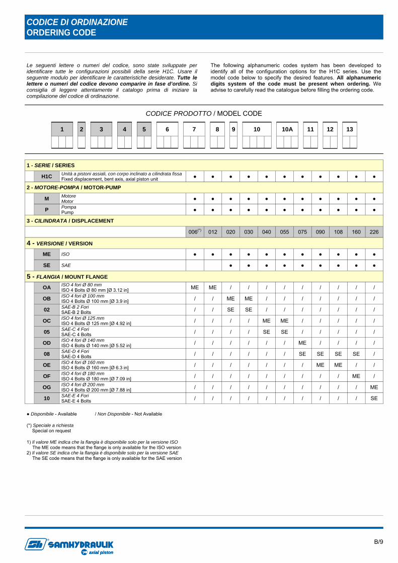
Le seguenti lettere o numeri del codice, sono state sviluppate per identificare tutte le configurazioni possibili della serie H1C. Usare il seguente modulo per identificare le caratteristiche desiderate. Tutte le lettere o numeri del codice devono comparire in fase d’ordine. Si consiglia di leggere attentamente il catalogo prima di iniziare la compilazione del codice di ordinazione.
The following alphanumeric codes system has been developed to identify all of the configuration options for the H1C series. Use the model code below to specify the desired features. All alphanumeric digits system of the code must be present when ordering. We advise to carefully read the catalogue before filling the ordering code.
CODICE PRODOTTO / MODEL CODE
CODICE DI ORDINAZIONE ORDERING CODE
3
4
8
6
5
7
11
10
13
10A
9
12
2
1 - SERIE / SERIES H1C Unità a pistoni assiali, con corpo inclinato a cilindrata fissa
Fixed displacement, bent axis, axial piston unit ● ● ● ● ● ● ● ● ● ● ●
2 - MOTORE-POMPA / MOTOR-PUMP
M Motore
Motor ● ● ● ● ● ● ● ● ● ● ●
P Pompa Pump ● ● ● ● ● ● ● ● ● ● ●
3 - CILINDRATA / DISPLACEMENT 006(*) 012 020 030 040 055 075 090 108 160 226
4 - VERSIONE / VERSION
ME ISO ● ● ● ● ● ● ● ● ● ● ●
SE SAE ● ● ● ● ● ● ● ● ●
5 - FLANGIA / MOUNT FLANGE
OA ISO 4 fori Ø 80 mm ISO 4 Bolts Ø 80 mm [Ø 3.12 in] ME ME / / / / / / / / /
OB ISO 4 fori Ø 100 mm ISO 4 Bolts Ø 100 mm [Ø 3.9 in] / / ME ME / / / / / / /
02 SAE-B 2 Fori SAE-B 2 Bolts / / SE SE / / / / / / /
OC ISO 4 fori Ø 125 mm ISO 4 Bolts Ø 125 mm [Ø 4.92 in] / / / / ME ME / / / / /
05 SAE-C 4 Fori SAE-C 4 Bolts / / / / SE SE / / / / /
OD ISO 4 fori Ø 140 mm ISO 4 Bolts Ø 140 mm [Ø 5.52 in] / / / / / / ME / / / /
08 SAE-D 4 Fori SAE-D 4 Bolts / / / / / / SE SE SE SE /
OE ISO 4 fori Ø 160 mm ISO 4 Bolts Ø 160 mm [Ø 6.3 in] / / / / / / / ME ME / /
OF ISO 4 fori Ø 180 mm ISO 4 Bolts Ø 180 mm [Ø 7.09 in] / / / / / / / / / ME /
OG ISO 4 fori Ø 200 mm ISO 4 Bolts Ø 200 mm [Ø 7.88 in] / / / / / / / / / / ME
10 SAE-E 4 Fori SAE-E 4 Bolts / / / / / / / / / / SE
1
1) Il valore ME indica che la flangia è disponibile solo per la versione ISO The ME code means that the flange is only available for the ISO version
2) Il valore SE indica che la flangia è disponibile solo per la versione SAE The SE code means that the flange is only available for the SAE version
● Disponibile - Available / Non Disponibile - Not Available
(*) Speciale a richiesta Special on request
B/10
axial piston
R
axial pistonaxial piston
R
3
4
8
6
5
7
11
10
13
10A
9
12
2
1
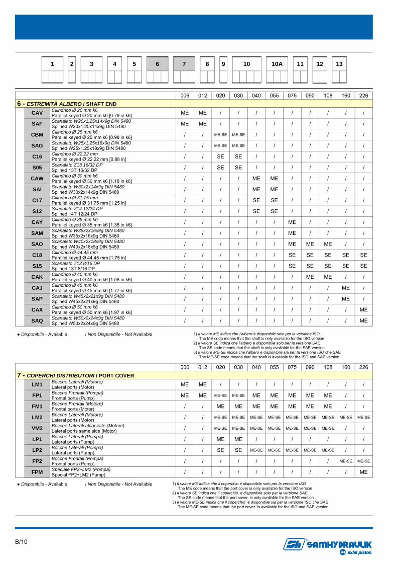
006 012 020 030 040 055 075 090 108 160 226 6 - ESTREMITÀ ALBERO / SHAFT END
CAV Cilindrico Ø 20 mm k6 Parallel keyed Ø 20 mm k6 [0.79 in k6] ME ME / / / / / / / / /
SAF Scanalato W20x1.25x14x9g DIN 5480 Splined W20x1.25x14x9g DIN 5480 ME ME / / / / / / / / /
CBM Cilindrico Ø 25 mm k6 Parallel keyed Ø 25 mm k6 [0.98 in k6] / / ME-SE ME-SE / / / / / / /
SAG Scanalato W25x1.25x18x9g DIN 5480 Splined W25x1.25x18x9g DIN 5480 / / ME-SE ME-SE / / / / / / /
C16 Cilindrico Ø 22.22 mm Parallel keyed Ø 22.22 mm [0.88 in] / / SE SE / / / / / / /
S05 Scanalato Z13 16/32 DP Splined 13T 16/32 DP / / SE SE / / / / / / /
CAW Cilindrico Ø 30 mm k6 Parallel keyed Ø 30 mm k6 [1.18 in k6] / / / / ME ME / / / / /
SAI Scanalato W30x2x14x9g DIN 5480 Splined W30x2x14x9g DIN 5480 / / / / ME ME / / / / /
C17 Cilindrico Ø 31.75 mm Parallel keyed Ø 31.75 mm [1.25 in] / / / / SE SE / / / / /
S12 Scanalato Z14 12/24 DP Splined 14T 12/24 DP / / / / SE SE / / / / /
CAY Cilindrico Ø 35 mm k6 Parallel keyed Ø 35 mm k6 [1.38 in k6] / / / / / / ME / / / /
SAM Scanalato W35x2x16x9g DIN 5480 Splined W35x2x16x9g DIN 5480 / / / / / / ME / / / /
SAO Scanalato W40x2x18x9g DIN 5480 Splined W40x2x18x9g DIN 5480 / / / / / / ME ME ME / /
C18 Cilindrico Ø 44.45 mm Parallel keyed Ø 44.45 mm [1.75 in] / / / / / / SE SE SE SE SE
S15 Scanalato Z13 8/16 DP Splined 13T 8/16 DP / / / / / / SE SE SE SE SE
CAK Cilindrico Ø 40 mm k6 Parallel keyed Ø 40 mm k6 [1.58 in k6] / / / / / / / ME ME / /
CAJ Cilindrico Ø 45 mm k6 Parallel keyed Ø 45 mm k6 [1.77 in k6] / / / / / / / / / ME /
SAP Scanalato W45x2x21x9g DIN 5480 Splined W45x2x21x9g DIN 5480 / / / / / / / / / ME /
CAX Cilindrico Ø 50 mm k6 Parallel keyed Ø 50 mm k6 [1.97 in k6] / / / / / / / / / / ME
SAQ Scanalato W50x2x24x9g DIN 5480 Splined W50x2x24x9g DIN 5480 / / / / / / / / / / ME
006 012 020 030 040 055 075 090 108 160 226 7 - COPERCHI DISTRIBUTORI / PORT COVER
LM1 Bocche Laterali (Motore) Lateral ports (Motor) ME ME / / / / / / / / /
FP1 Bocche Frontali (Pompa) Frontal ports (Pump) ME ME ME-SE ME-SE ME ME ME ME ME / /
FM1 Bocche Frontali (Motore) Frontal ports (Motor) / / ME ME ME ME ME ME ME / /
LM2 Bocche Laterali (Motore) Lateral ports (Motor) / / ME-SE ME-SE ME-SE ME-SE ME-SE ME-SE ME-SE ME-SE ME-SE
VM2 Bocche Laterali affiancate (Motore) Lateral ports same side (Motor) / / ME-SE ME-SE ME-SE ME-SE ME-SE ME-SE ME-SE / /
LP1 Bocche Laterali (Pompa) Lateral ports (Pump) / / ME ME / / / / / / /
LP2 Bocche Laterali (Pompa) Lateral ports (Pump) / / SE SE ME-SE ME-SE ME-SE ME-SE ME-SE / /
FP2 Bocche Frontali (Pompa) Frontal ports (Pump) / / / / / / / / / ME-SE ME-SE
FPM Speciale FP2+LM2 (Pompa) Special FP2+LM2 (Pump) / / / / / / / / / / ME
1) Il valore ME indica che il coperchio è disponibile solo per la versione ISO The ME code means that the port cover is only available for the ISO version
2) Il valore SE indica che il coperchio è disponibile solo per la versione SAE The SE code means that the port cover is only available for the SAE version
3) Il valore ME-SE indica che il coperchio è disponibile sia per la versione ISO che SAE The ME-SE code means that the port cover is available for the ISO and SAE version
● Disponibile - Available / Non Disponibile - Not Available
● Disponibile - Available / Non Disponibile - Not Available
1) Il valore ME indica che l’albero è disponibile solo per la versione ISO The ME code means that the shaft is only available for the ISO version
2) Il valore SE indica che l’albero è disponibile solo per la versione SAE The SE code means that the shaft is only available for the SAE version
3) Il valore ME-SE indica che l’albero è disponibile sia per la versione ISO che SAE The ME-SE code means that the shaft is available for the ISO and SAE version
B/11
axial piston
R
axial pistonaxial piston
R
3
4
8
6
5
7
11
10
13
10A
9
12
2
1
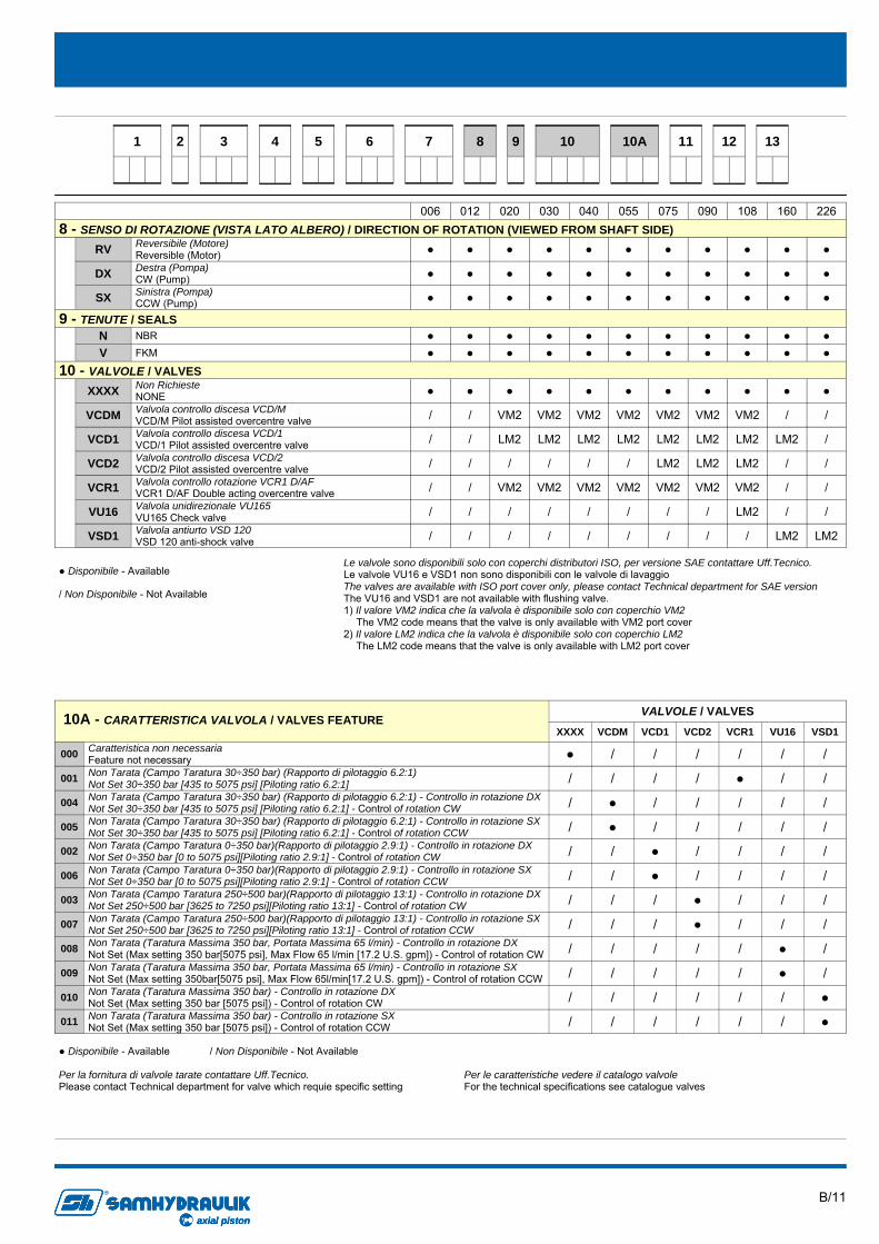
006 012 020 030 040 055 075 090 108 160 226 8 - SENSO DI ROTAZIONE (VISTA LATO ALBERO) / DIRECTION OF ROTATION (VIEWED FROM SHAFT SIDE)
RV Reversibile (Motore) Reversible (Motor) ● ● ● ● ● ● ● ● ● ● ●
DX Destra (Pompa) CW (Pump) ● ● ● ● ● ● ● ● ● ● ●
SX Sinistra (Pompa) CCW (Pump) ● ● ● ● ● ● ● ● ● ● ●
9 - TENUTE / SEALS N NBR ● ● ● ● ● ● ● ● ● ● ● V FKM ● ● ● ● ● ● ● ● ● ● ●
10 - VALVOLE / VALVES
XXXX Non Richieste NONE ● ● ● ● ● ● ● ● ● ● ●
VCDM Valvola controllo discesa VCD/M VCD/M Pilot assisted overcentre valve / / VM2 VM2 VM2 VM2 VM2 VM2 VM2 / /
VCD1 Valvola controllo discesa VCD/1 VCD/1 Pilot assisted overcentre valve / / LM2 LM2 LM2 LM2 LM2 LM2 LM2 LM2 /
VCD2 Valvola controllo discesa VCD/2 VCD/2 Pilot assisted overcentre valve / / / / / / LM2 LM2 LM2 / /
VCR1 Valvola controllo rotazione VCR1 D/AF VCR1 D/AF Double acting overcentre valve / / VM2 VM2 VM2 VM2 VM2 VM2 VM2 / /
VU16 Valvola unidirezionale VU165 VU165 Check valve / / / / / / / / LM2 / /
VSD1 Valvola antiurto VSD 120 VSD 120 anti-shock valve / / / / / / / / / LM2 LM2
Le valvole sono disponibili solo con coperchi distributori ISO, per versione SAE contattare Uff.Tecnico. Le valvole VU16 e VSD1 non sono disponibili con le valvole di lavaggio The valves are available with ISO port cover only, please contact Technical department for SAE version The VU16 and VSD1 are not available with flushing valve. 1) Il valore VM2 indica che la valvola è disponibile solo con coperchio VM2
The VM2 code means that the valve is only available with VM2 port cover 2) Il valore LM2 indica che la valvola è disponibile solo con coperchio LM2
The LM2 code means that the valve is only available with LM2 port cover
XXXX VCDM VCD1 VCD2 VCR1 VU16 VSD1
000 Caratteristica non necessaria Feature not necessary ● / / / / / /
001 Non Tarata (Campo Taratura 30÷350 bar) (Rapporto di pilotaggio 6.2:1) Not Set 30÷350 bar [435 to 5075 psi] [Piloting ratio 6.2:1] / / / / ● / /
004 Non Tarata (Campo Taratura 30÷350 bar) (Rapporto di pilotaggio 6.2:1) - Controllo in rotazione DX Not Set 30÷350 bar [435 to 5075 psi] [Piloting ratio 6.2:1] - Control of rotation CW / ● / / / / /
005 Non Tarata (Campo Taratura 30÷350 bar) (Rapporto di pilotaggio 6.2:1) - Controllo in rotazione SX Not Set 30÷350 bar [435 to 5075 psi] [Piloting ratio 6.2:1] - Control of rotation CCW / ● / / / / /
002 Non Tarata (Campo Taratura 0÷350 bar)(Rapporto di pilotaggio 2.9:1) - Controllo in rotazione DX Not Set 0÷350 bar [0 to 5075 psi][Piloting ratio 2.9:1] - Control of rotation CW / / ● / / / /
006 Non Tarata (Campo Taratura 0÷350 bar)(Rapporto di pilotaggio 2.9:1) - Controllo in rotazione SX Not Set 0÷350 bar [0 to 5075 psi][Piloting ratio 2.9:1] - Control of rotation CCW / / ● / / / /
003 Non Tarata (Campo Taratura 250÷500 bar)(Rapporto di pilotaggio 13:1) - Controllo in rotazione DX Not Set 250÷500 bar [3625 to 7250 psi][Piloting ratio 13:1] - Control of rotation CW / / / ● / / /
007 Non Tarata (Campo Taratura 250÷500 bar)(Rapporto di pilotaggio 13:1) - Controllo in rotazione SX Not Set 250÷500 bar [3625 to 7250 psi][Piloting ratio 13:1] - Control of rotation CCW / / / ● / / /
008 Non Tarata (Taratura Massima 350 bar, Portata Massima 65 l/min) - Controllo in rotazione DX Not Set (Max setting 350 bar[5075 psi], Max Flow 65 l/min [17.2 U.S. gpm]) - Control of rotation CW / / / / / ● /
009 Non Tarata (Taratura Massima 350 bar, Portata Massima 65 l/min) - Controllo in rotazione SX Not Set (Max setting 350bar[5075 psi], Max Flow 65l/min[17.2 U.S. gpm]) - Control of rotation CCW / / / / / ● /
VALVOLE / VALVES
010 Non Tarata (Taratura Massima 350 bar) - Controllo in rotazione DX Not Set (Max setting 350 bar [5075 psi]) - Control of rotation CW / / / / / / ●
011 Non Tarata (Taratura Massima 350 bar) - Controllo in rotazione SX Not Set (Max setting 350 bar [5075 psi]) - Control of rotation CCW / / / / / / ●
10A - CARATTERISTICA VALVOLA / VALVES FEATURE
● Disponibile - Available / Non Disponibile - Not Available
Per la fornitura di valvole tarate contattare Uff.Tecnico. Please contact Technical department for valve which requie specific setting
Per le caratteristiche vedere il catalogo valvole For the technical specifications see catalogue valves
● Disponibile - Available
/ Non Disponibile - Not Available
B/12
axial piston
R
axial pistonaxial piston
R
3
4
8
6
5
7
11
10
13
10A
9
12
2
1
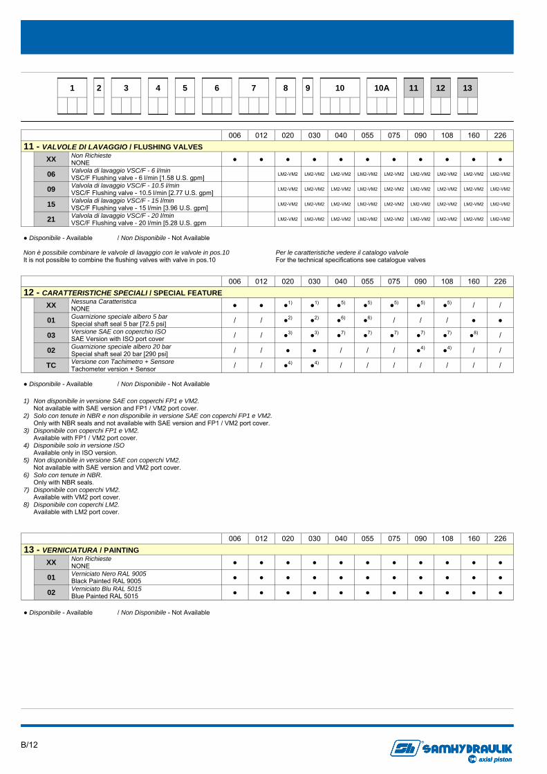
006 012 020 030 040 055 075 090 108 160 226
XX Non Richieste NONE ● ● ● ● ● ● ● ● ● ● ●
06 Valvola di lavaggio VSC/F - 6 l/min VSC/F Flushing valve - 6 l/min [1.58 U.S. gpm] LM2-VM2 LM2-VM2 LM2-VM2 LM2-VM2 LM2-VM2 LM2-VM2 LM2-VM2 LM2-VM2 LM2-VM2
09 Valvola di lavaggio VSC/F - 10.5 l/min VSC/F Flushing valve - 10.5 l/min [2.77 U.S. gpm] LM2-VM2 LM2-VM2 LM2-VM2 LM2-VM2 LM2-VM2 LM2-VM2 LM2-VM2 LM2-VM2 LM2-VM2
15 Valvola di lavaggio VSC/F - 15 l/min VSC/F Flushing valve - 15 l/min [3.96 U.S. gpm] LM2-VM2 LM2-VM2 LM2-VM2 LM2-VM2 LM2-VM2 LM2-VM2 LM2-VM2 LM2-VM2 LM2-VM2
21 Valvola di lavaggio VSC/F - 20 l/min VSC/F Flushing valve - 20 l/min [5.28 U.S. gpm LM2-VM2 LM2-VM2 LM2-VM2 LM2-VM2 LM2-VM2 LM2-VM2 LM2-VM2 LM2-VM2 LM2-VM2
11 - VALVOLE DI LAVAGGIO / FLUSHING VALVES
● Disponibile - Available / Non Disponibile - Not Available
Non è possibile combinare le valvole di lavaggio con le valvole in pos.10 It is not possible to combine the flushing valves with valve in pos.10
Per le caratteristiche vedere il catalogo valvole For the technical specifications see catalogue valves
006 012 020 030 040 055 075 090 108 160 226
XX Nessuna Caratteristica NONE ● ● ●1) ●1) ●5) ●5) ●5) ●5) ●5) / /
01 Guarnizione speciale albero 5 bar Special shaft seal 5 bar [72.5 psi] / / ●2) ●2) ●6) ●6) / / / ● ●
03 Versione SAE con coperchio ISO SAE Version with ISO port cover / / ●3) ●3) ●7) ●7) ●7) ●7) ●7) ●8) /
02 Guarnizione speciale albero 20 bar Special shaft seal 20 bar [290 psi] / / ● ● / / / ●4) ●4) / /
TC Versione con Tachimetro + Sensore Tachometer version + Sensor / / ●4) ●4) / / / / / / /
12 - CARATTERISTICHE SPECIALI / SPECIAL FEATURE
1) Non disponibile in versione SAE con coperchi FP1 e VM2. Not available with SAE version and FP1 / VM2 port cover.
2) Solo con tenute in NBR e non disponibile in versione SAE con coperchi FP1 e VM2. Only with NBR seals and not available with SAE version and FP1 / VM2 port cover.
3) Disponibile con coperchi FP1 e VM2. Available with FP1 / VM2 port cover.
4) Disponibile solo in versione ISO Available only in ISO version.
5) Non disponibile in versione SAE con coperchi VM2. Not available with SAE version and VM2 port cover.
6) Solo con tenute in NBR. Only with NBR seals.
7) Disponibile con coperchi VM2. Available with VM2 port cover.
8) Disponibile con coperchi LM2. Available with LM2 port cover.
● Disponibile - Available / Non Disponibile - Not Available
006 012 020 030 040 055 075 090 108 160 226 13 - VERNICIATURA / PAINTING
XX Non Richieste NONE ● ● ● ● ● ● ● ● ● ● ●
01 Verniciato Nero RAL 9005 Black Painted RAL 9005 ● ● ● ● ● ● ● ● ● ● ●
02 Verniciato Blu RAL 5015 Blue Painted RAL 5015 ● ● ● ● ● ● ● ● ● ● ●
● Disponibile - Available / Non Disponibile - Not Available
B/13
axial piston
R
axial pistonaxial piston
R
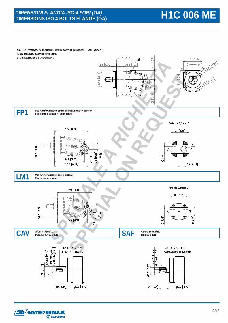
DIMENSIONI FLANGIA ISO 4 FORI (OA) DIMENSIONS ISO 4 BOLTS FLANGE (OA) H1C 006 ME
FP1 Per funzionamento come pompa (circuito aperto) For pump operation (open circuit)
LM1 Per funzionamento come motore For motor operation
CAV Albero cilindico Parallel keyed shaft SAF Albero scanalato
Splined shaft
S1, S2: Drenaggi (1 tappato) / Drain ports (1 plugged) - 3/8 G (BSPP) A, B: Utenze / Service line ports S: Aspirazione / Suction port
B/14
axial piston
R
axial pistonaxial piston
R
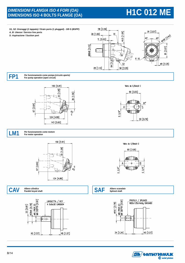
DIMENSIONI FLANGIA ISO 4 FORI (OA) DIMENSIONS ISO 4 BOLTS FLANGE (OA) H1C 012 ME
S1, S2: Drenaggi (1 tappato) / Drain ports (1 plugged) - 3/8 G (BSPP) A, B: Utenze / Service line ports S: Aspirazione / Suction port
FP1 Per funzionamento come pompa (circuito aperto) For pump operation (open circuit)
LM1 Per funzionamento come motore For motor operation
CAV Albero cilindico Parallel keyed shaft SAF Albero scanalato
Splined shaft
B/15
axial piston
R
axial pistonaxial piston
R
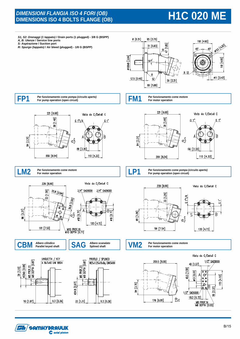
DIMENSIONI FLANGIA ISO 4 FORI (OB) DIMENSIONS ISO 4 BOLTS FLANGE (OB) H1C 020 ME
S1, S2: Drenaggi (1 tappato) / Drain ports (1 plugged) - 3/8 G (BSPP) A, B: Utenze / Service line ports S: Aspirazione / Suction port R: Spurgo (tappato) / Air bleed (plugged) - 1/8 G (BSPP)
CBM Albero cilindico Parallel keyed shaft SAG Albero scanalato
Splined shaft
FP1 Per funzionamento come pompa (circuito aperto) For pump operation (open circuit) FM1 Per funzionamento come motore
For motor operation
LM2 Per funzionamento come motore For motor operation LP1 Per funzionamento come pompa (circuito aperto)
For pump operation (open circuit)
VM2 Per funzionamento come motore For motor operation
B/16
axial piston
R
axial pistonaxial piston
R
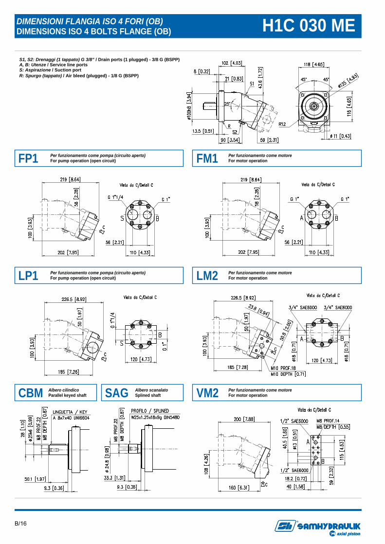
DIMENSIONI FLANGIA ISO 4 FORI (OB) DIMENSIONS ISO 4 BOLTS FLANGE (OB) H1C 030 ME
S1, S2: Drenaggi (1 tappato) G 3/8” / Drain ports (1 plugged) - 3/8 G (BSPP) A, B: Utenze / Service line ports S: Aspirazione / Suction port R: Spurgo (tappato) / Air bleed (plugged) - 1/8 G (BSPP)
FP1 Per funzionamento come pompa (circuito aperto) For pump operation (open circuit) FM1 Per funzionamento come motore
For motor operation
LP1 Per funzionamento come pompa (circuito aperto) For pump operation (open circuit) LM2 Per funzionamento come motore
For motor operation
CBM Albero cilindico Parallel keyed shaft SAG Albero scanalato
Splined shaft VM2 Per funzionamento come motore For motor operation
B/17
axial piston
R
axial pistonaxial piston
R
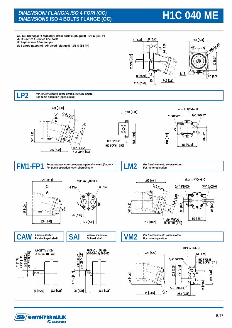
DIMENSIONI FLANGIA ISO 4 FORI (OC) DIMENSIONS ISO 4 BOLTS FLANGE (OC) H1C 040 ME
S1, S2: Drenaggi (1 tappato) / Drain ports (1 plugged) - 1/2 G (BSPP) A, B: Utenze / Service line ports S: Aspirazione / Suction port R: Spurgo (tappato) / Air bleed (plugged) - 1/8 G (BSPP)
LP2 Per funzionamento come pompa (circuito aperto) For pump operation (open circuit)
FM1-FP1 Per funzionamento come pompa (circuito aperto)/motore For pump operation (open circuit)/motor LM2 Per funzionamento come motore
For motor operation
CAW Albero cilindico Parallel keyed shaft SAI Albero scanalato
Splined shaft VM2 Per funzionamento come motore For motor operation
B/18
axial piston
R
axial pistonaxial piston
R
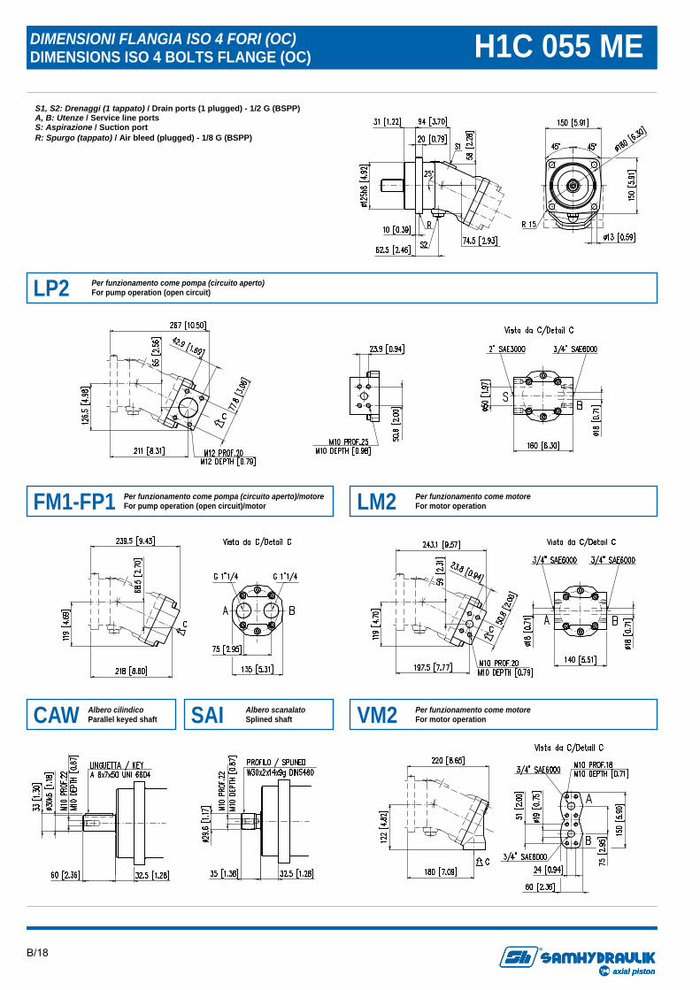
DIMENSIONI FLANGIA ISO 4 FORI (OC) DIMENSIONS ISO 4 BOLTS FLANGE (OC) H1C 055 ME
S1, S2: Drenaggi (1 tappato) / Drain ports (1 plugged) - 1/2 G (BSPP) A, B: Utenze / Service line ports S: Aspirazione / Suction port R: Spurgo (tappato) / Air bleed (plugged) - 1/8 G (BSPP)
LP2 Per funzionamento come pompa (circuito aperto) For pump operation (open circuit)
FM1-FP1 Per funzionamento come pompa (circuito aperto)/motore For pump operation (open circuit)/motor LM2 Per funzionamento come motore
For motor operation
CAW Albero cilindico Parallel keyed shaft SAI Albero scanalato
Splined shaft VM2 Per funzionamento come motore For motor operation
B/19
axial piston
R
axial pistonaxial piston
R
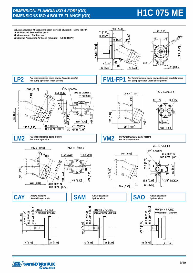
DIMENSIONI FLANGIA ISO 4 FORI (OD) DIMENSIONS ISO 4 BOLTS FLANGE (OD) H1C 075 ME
S1, S2: Drenaggi (1 tappato) / Drain ports (1 plugged) - 1/2 G (BSPP) A, B: Utenze / Service line ports S: Aspirazione / Suction port R: Spurgo (tappato) / Air bleed (plugged) - 1/8 G (BSPP)
LM2 Per funzionamento come motore For motor operation
LP2 Per funzionamento come pompa (circuito aperto) For pump operation (open circuit) FM1-FP1 Per funzionamento come pompa (circuito aperto)/motore
For pump operation (open circuit)/motor
VM2 Per funzionamento come motore For motor operation
CAY Albero cilindico Parallel keyed shaft SAM Albero scanalato
Splined shaft SAO Albero scanalato Splined shaft
B/20
axial piston
R
axial pistonaxial piston
R
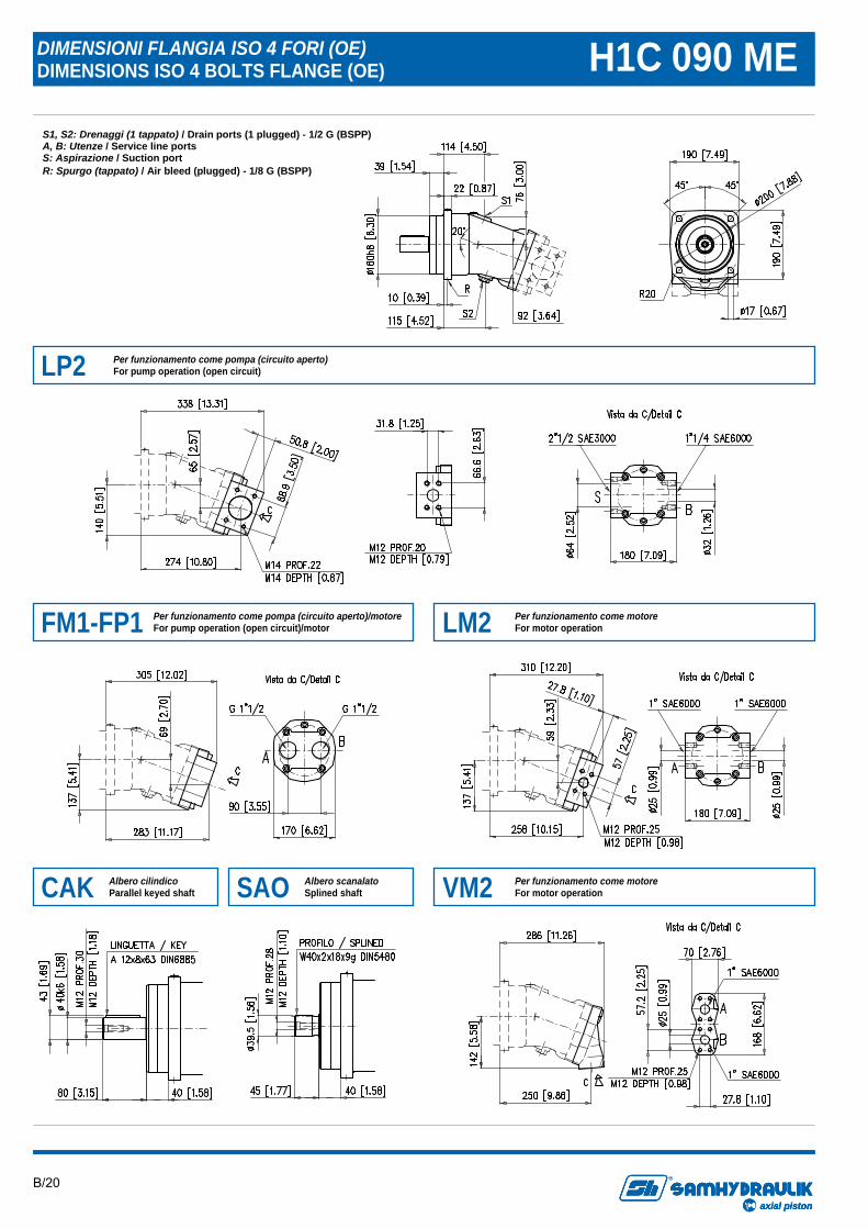
DIMENSIONI FLANGIA ISO 4 FORI (OE) DIMENSIONS ISO 4 BOLTS FLANGE (OE) H1C 090 ME S1, S2: Drenaggi (1 tappato) / Drain ports (1 plugged) - 1/2 G (BSPP) A, B: Utenze / Service line ports S: Aspirazione / Suction port R: Spurgo (tappato) / Air bleed (plugged) - 1/8 G (BSPP)
LP2 Per funzionamento come pompa (circuito aperto) For pump operation (open circuit)
FM1-FP1 Per funzionamento come pompa (circuito aperto)/motore For pump operation (open circuit)/motor LM2 Per funzionamento come motore
For motor operation
CAK Albero cilindico Parallel keyed shaft SAO Albero scanalato
Splined shaft VM2 Per funzionamento come motore For motor operation
B/21
axial piston
R
axial pistonaxial piston
R
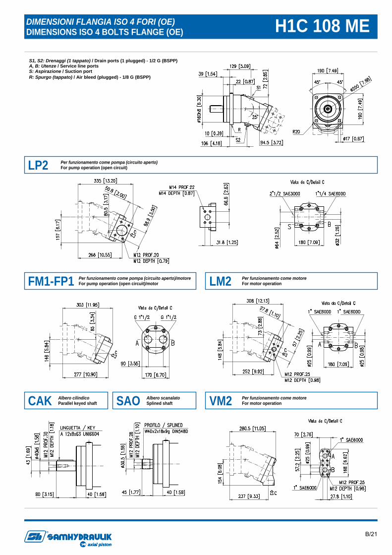
DIMENSIONI FLANGIA ISO 4 FORI (OE) DIMENSIONS ISO 4 BOLTS FLANGE (OE) H1C 108 ME
S1, S2: Drenaggi (1 tappato) / Drain ports (1 plugged) - 1/2 G (BSPP) A, B: Utenze / Service line ports S: Aspirazione / Suction port R: Spurgo (tappato) / Air bleed (plugged) - 1/8 G (BSPP)
LP2 Per funzionamento come pompa (circuito aperto) For pump operation (open circuit)
FM1-FP1 Per funzionamento come pompa (circuito aperto)/motore For pump operation (open circuit)/motor LM2 Per funzionamento come motore
For motor operation
CAK Albero cilindico Parallel keyed shaft SAO Albero scanalato
Splined shaft VM2 Per funzionamento come motore For motor operation
B/22
axial piston
R
axial pistonaxial piston
R
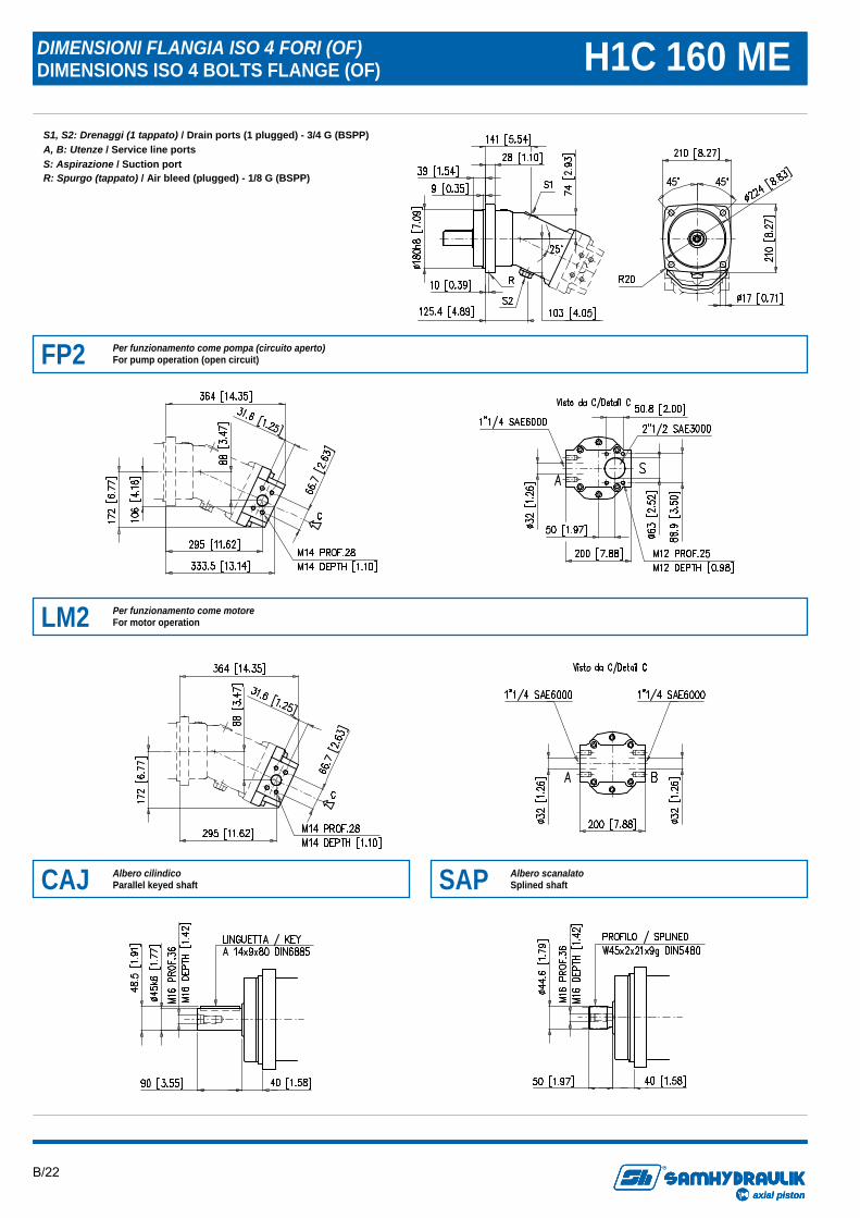
DIMENSIONI FLANGIA ISO 4 FORI (OF) DIMENSIONS ISO 4 BOLTS FLANGE (OF) H1C 160 ME
S1, S2: Drenaggi (1 tappato) / Drain ports (1 plugged) - 3/4 G (BSPP) A, B: Utenze / Service line ports S: Aspirazione / Suction port R: Spurgo (tappato) / Air bleed (plugged) - 1/8 G (BSPP)
FP2 Per funzionamento come pompa (circuito aperto) For pump operation (open circuit)
LM2 Per funzionamento come motore For motor operation
CAJ Albero cilindico Parallel keyed shaft SAP Albero scanalato
Splined shaft
B/23
axial piston
R
axial pistonaxial piston
R
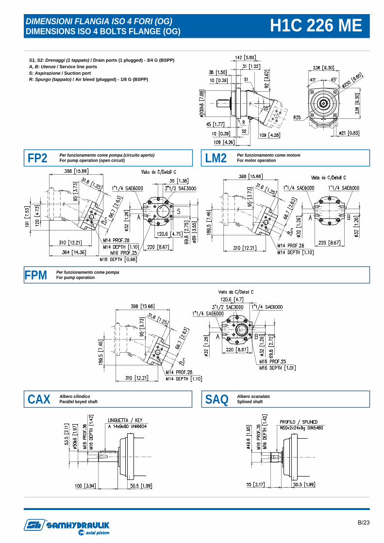
DIMENSIONI FLANGIA ISO 4 FORI (OG) DIMENSIONS ISO 4 BOLTS FLANGE (OG) H1C 226 ME
S1, S2: Drenaggi (1 tappato) / Drain ports (1 plugged) - 3/4 G (BSPP) A, B: Utenze / Service line ports S: Aspirazione / Suction port R: Spurgo (tappato) / Air bleed (plugged) - 1/8 G (BSPP)
FP2 Per funzionamento come pompa (circuito aperto) For pump operation (open circuit)
CAX Albero cilindico Parallel keyed shaft SAQ Albero scanalato
Splined shaft
FPM Per funzionamento come pompa For pump operation
LM2 Per funzionamento come motore For motor operation
B/24
axial piston
R
axial pistonaxial piston
R
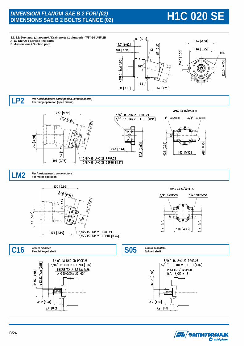
DIMENSIONI FLANGIA SAE B 2 FORI (02) DIMENSIONS SAE B 2 BOLTS FLANGE (02) H1C 020 SE S1, S2: Drenaggi (1 tappato) / Drain ports (1 plugged) - 7/8”-14 UNF 2B A, B: Utenze / Service line ports S: Aspirazione / Suction port
LP2 Per funzionamento come pompa (circuito aperto) For pump operation (open circuit)
LM2 Per funzionamento come motore For motor operation
C16 Albero cilindico Parallel keyed shaft S05 Albero scanalato
Splined shaft
B/25
axial piston
R
axial pistonaxial piston
R
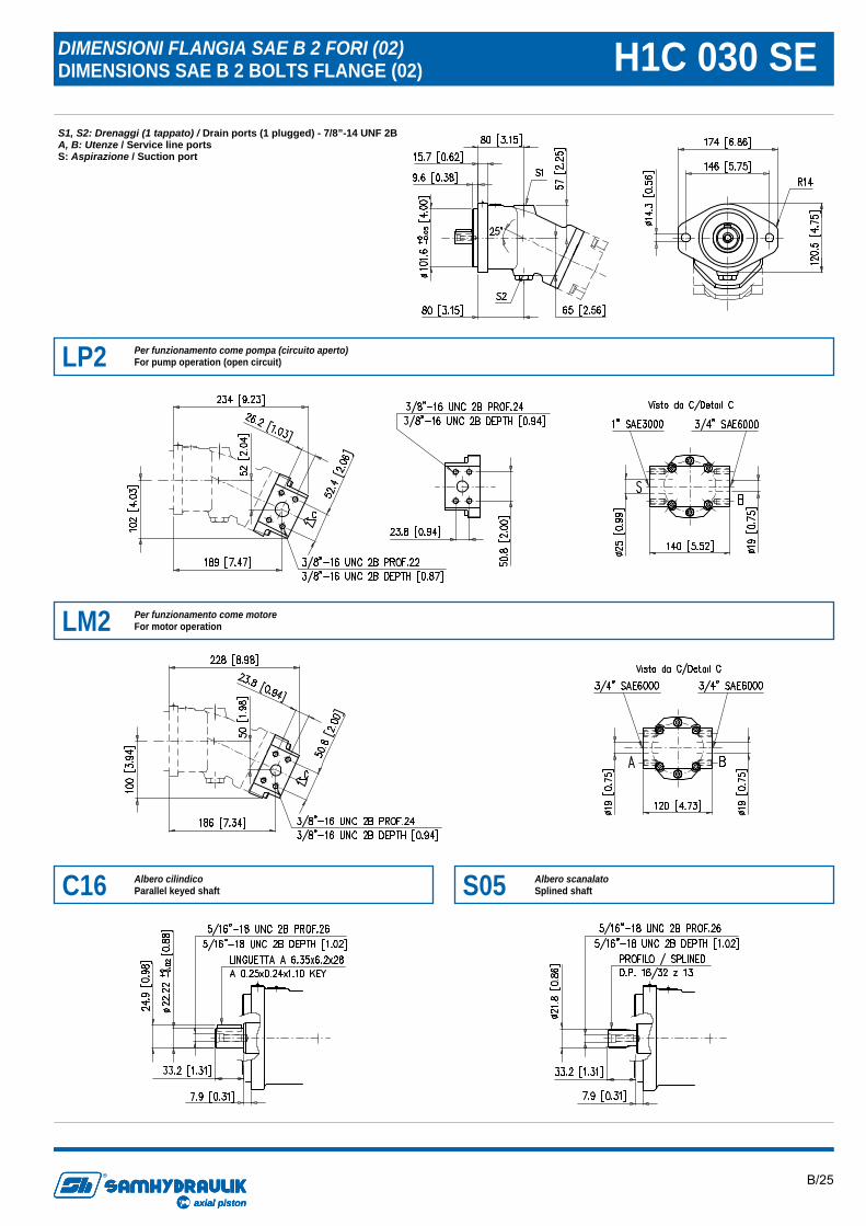
DIMENSIONI FLANGIA SAE B 2 FORI (02) DIMENSIONS SAE B 2 BOLTS FLANGE (02) H1C 030 SE S1, S2: Drenaggi (1 tappato) / Drain ports (1 plugged) - 7/8”-14 UNF 2B A, B: Utenze / Service line ports S: Aspirazione / Suction port
LP2 Per funzionamento come pompa (circuito aperto) For pump operation (open circuit)
LM2 Per funzionamento come motore For motor operation
C16 Albero cilindico Parallel keyed shaft S05 Albero scanalato
Splined shaft
B/26
axial piston
R
axial pistonaxial piston
R
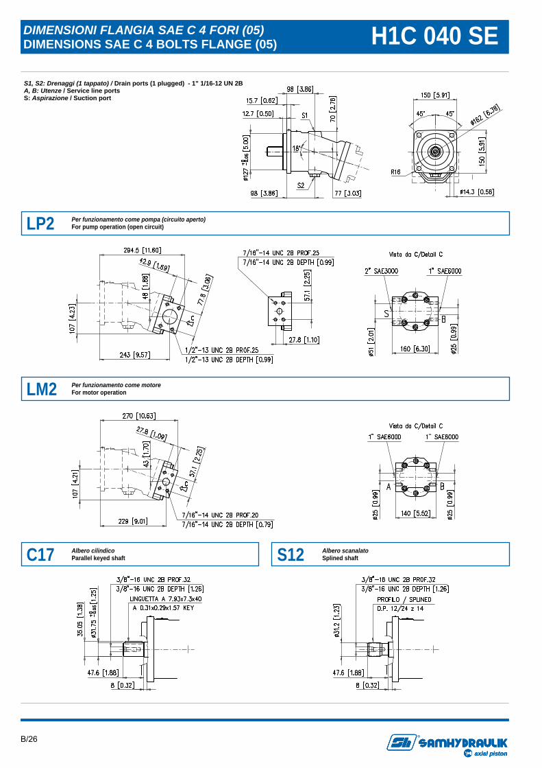
DIMENSIONI FLANGIA SAE C 4 FORI (05) DIMENSIONS SAE C 4 BOLTS FLANGE (05) H1C 040 SE S1, S2: Drenaggi (1 tappato) / Drain ports (1 plugged) - 1” 1/16-12 UN 2B A, B: Utenze / Service line ports S: Aspirazione / Suction port
LP2 Per funzionamento come pompa (circuito aperto) For pump operation (open circuit)
LM2 Per funzionamento come motore For motor operation
C17 Albero cilindico Parallel keyed shaft S12 Albero scanalato
Splined shaft
B/27
axial piston
R
axial pistonaxial piston
R
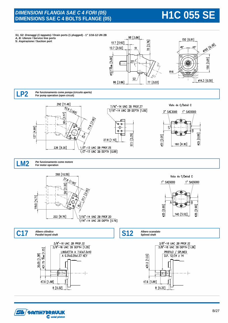
DIMENSIONI FLANGIA SAE C 4 FORI (05) DIMENSIONS SAE C 4 BOLTS FLANGE (05) H1C 055 SE S1, S2: Drenaggi (1 tappato) / Drain ports (1 plugged) - 1” 1/16-12 UN 2B A, B: Utenze / Service line ports S: Aspirazione / Suction port
LP2 Per funzionamento come pompa (circuito aperto) For pump operation (open circuit)
LM2 Per funzionamento come motore For motor operation
C17 Albero cilindico Parallel keyed shaft S12 Albero scanalato
Splined shaft
B/28
axial piston
R
axial pistonaxial piston
R
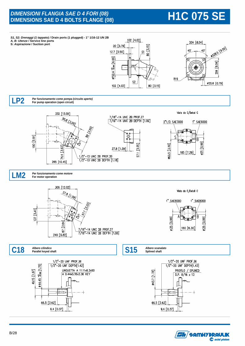
DIMENSIONI FLANGIA SAE D 4 FORI (08) DIMENSIONS SAE D 4 BOLTS FLANGE (08) H1C 075 SE S1, S2: Drenaggi (1 tappato) / Drain ports (1 plugged) - 1” 1/16-12 UN 2B A, B: Utenze / Service line ports S: Aspirazione / Suction port
LP2 Per funzionamento come pompa (circuito aperto) For pump operation (open circuit)
LM2 Per funzionamento come motore For motor operation
C18 Albero cilindico Parallel keyed shaft S15 Albero scanalato
Splined shaft
B/29
axial piston
R
axial pistonaxial piston
R
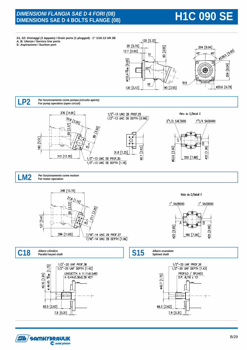
DIMENSIONI FLANGIA SAE D 4 FORI (08) DIMENSIONS SAE D 4 BOLTS FLANGE (08) H1C 090 SE S1, S2: Drenaggi (1 tappato) / Drain ports (1 plugged) - 1” 1/16-12 UN 2B A, B: Utenze / Service line ports S: Aspirazione / Suction port
LP2 Per funzionamento come pompa (circuito aperto) For pump operation (open circuit)
LM2 Per funzionamento come motore For motor operation
C18 Albero cilindico Parallel keyed shaft S15 Albero scanalato
Splined shaft
B/30
axial piston
R
axial pistonaxial piston
R
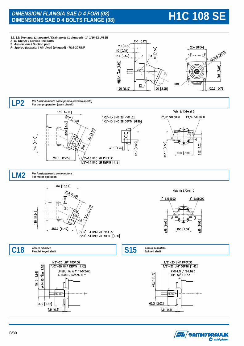
DIMENSIONI FLANGIA SAE D 4 FORI (08) DIMENSIONS SAE D 4 BOLTS FLANGE (08) H1C 108 SE
S1, S2: Drenaggi (1 tappato) / Drain ports (1 plugged) - 1” 1/16-12 UN 2B A, B: Utenze / Service line ports S: Aspirazione / Suction port R: Spurgo (tappato) / Air bleed (plugged) - 7/16-20 UNF
LP2 Per funzionamento come pompa (circuito aperto) For pump operation (open circuit)
LM2 Per funzionamento come motore For motor operation
C18 Albero cilindico Parallel keyed shaft S15 Albero scanalato
Splined shaft
B/31
axial piston
R
axial pistonaxial piston
R
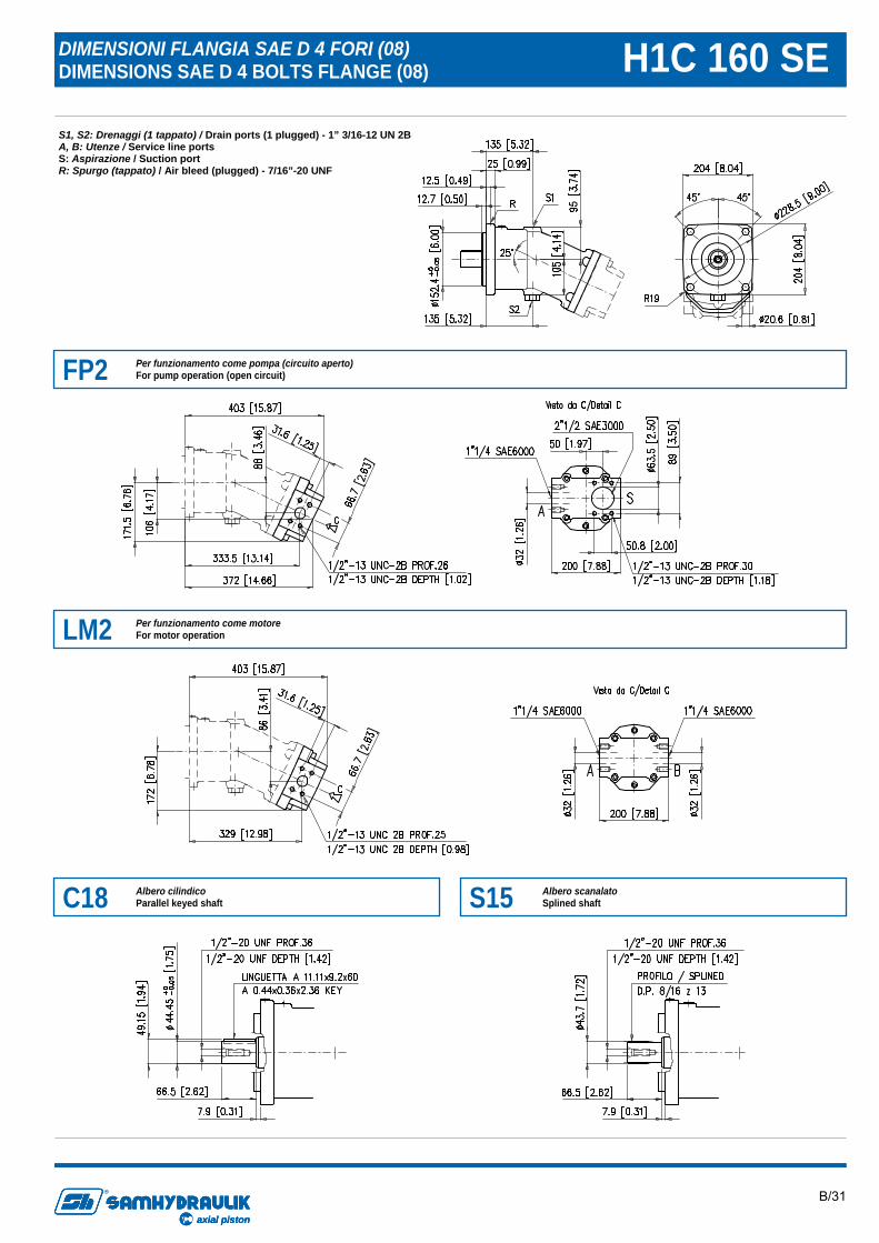
DIMENSIONI FLANGIA SAE D 4 FORI (08) DIMENSIONS SAE D 4 BOLTS FLANGE (08) H1C 160 SE S1, S2: Drenaggi (1 tappato) / Drain ports (1 plugged) - 1” 3/16-12 UN 2B A, B: Utenze / Service line ports S: Aspirazione / Suction port R: Spurgo (tappato) / Air bleed (plugged) - 7/16”-20 UNF
FP2 Per funzionamento come pompa (circuito aperto) For pump operation (open circuit)
LM2 Per funzionamento come motore For motor operation
C18 Albero cilindico Parallel keyed shaft S15 Albero scanalato
Splined shaft
B/32
axial piston
R
axial pistonaxial piston
R
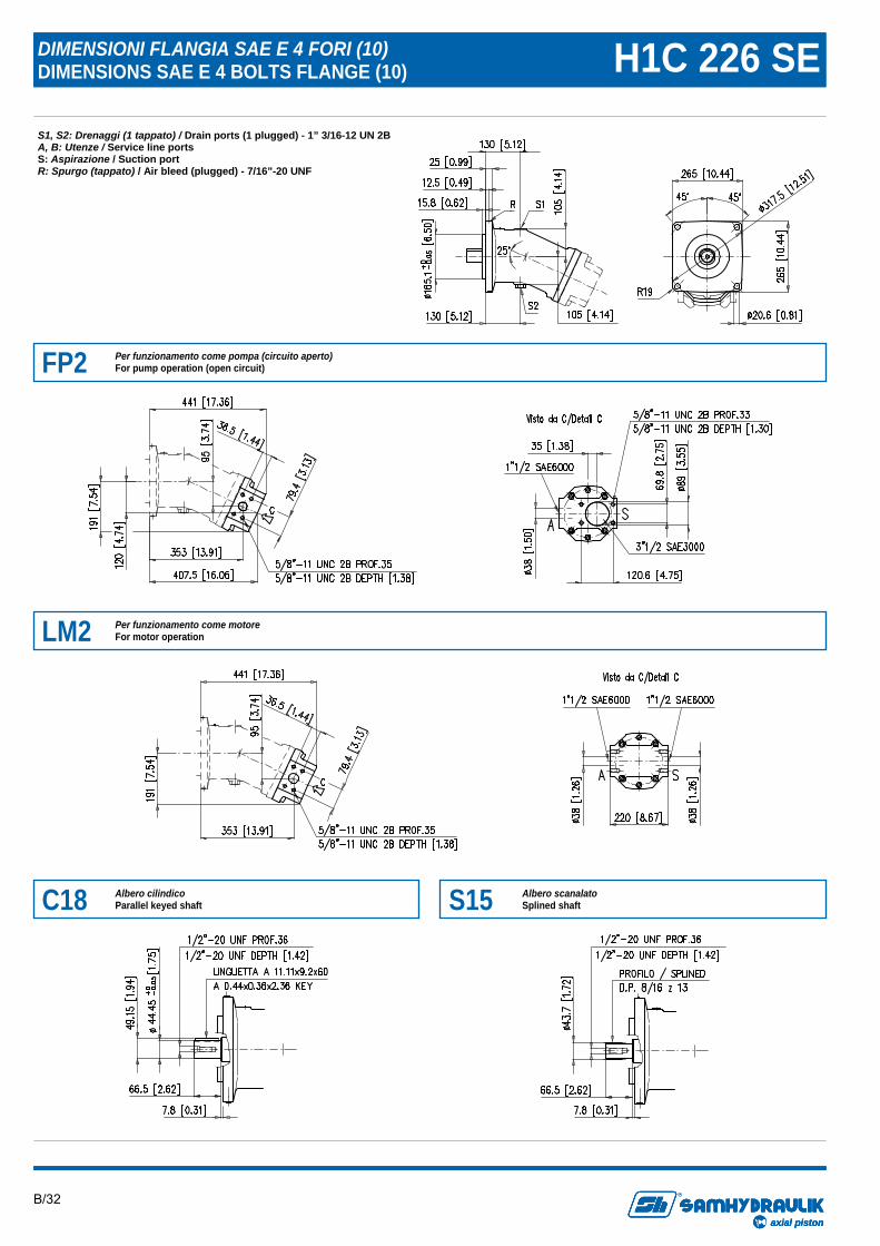
DIMENSIONI FLANGIA SAE E 4 FORI (10) DIMENSIONS SAE E 4 BOLTS FLANGE (10) H1C 226 SE S1, S2: Drenaggi (1 tappato) / Drain ports (1 plugged) - 1” 3/16-12 UN 2B A, B: Utenze / Service line ports S: Aspirazione / Suction port R: Spurgo (tappato) / Air bleed (plugged) - 7/16”-20 UNF
FP2 Per funzionamento come pompa (circuito aperto) For pump operation (open circuit)
LM2 Per funzionamento come motore For motor operation
C18 Albero cilindico Parallel keyed shaft S15 Albero scanalato
Splined shaft
B/33
axial piston
R
axial pistonaxial piston
R
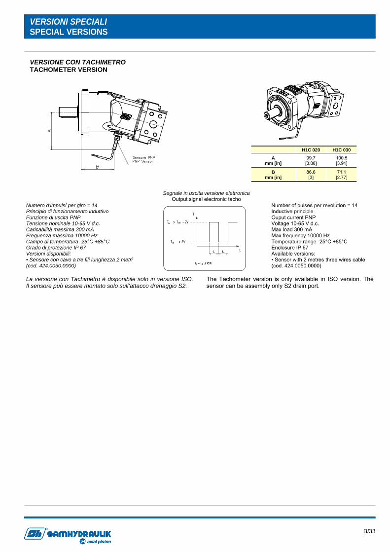
VERSIONI SPECIALI SPECIAL VERSIONS
VERSIONE CON TACHIMETRO TACHOMETER VERSION
La versione con Tachimetro è disponibile solo in versione ISO. Il sensore può essere montato solo sull’attacco drenaggio S2.
The Tachometer version is only available in ISO version. The sensor can be assembly only S2 drain port.
Segnale in uscita versione elettronica Output signal electronic tacho
Numero d'impulsi per giro = 14 Principio di funzionamento induttivo Funzione di uscita PNP Tensione nominale 10-65 V d.c. Caricabilità massima 300 mA Frequenza massima 10000 Hz Campo di temperatura -25°C +85°C Grado di protezione IP 67 Versioni disponibili: • Sensore con cavo a tre fili lunghezza 2 metri (cod. 424.0050.0000)
Number of pulses per revolution = 14 Inductive principle Ouput current PNP Voltage 10-65 V d.c. Max load 300 mA Max frequency 10000 Hz Temperature range -25°C +85°C Enclosure IP 67 Available versions: • Sensor with 2 metres three wires cable (cod. 424.0050.0000)
H1C 020
A mm [in]
99.7 [3.88]
B mm [in]
86.6 [3]
H1C 030
100.5 [3.91]
71.1 [2.77]
B/34
axial piston
R
axial pistonaxial piston
R
Informazioni sul prodotto Dati i continui sviluppi, le modifiche e le migliorie al prodotto, la S.AM Hydraulik Spa non sarà responsabile per eventuali informazioni che possano indurre in errore, od erronee, riportate da cataloghi, istruzioni, disegni, dati tecnici e altri dati forniti dalla S.A.M. Hydraulik Spa. Non sarà possibile basare alcun procedimento legale su tale materiale. Modifiche del prodotto. La S.A.M. Hydraulik Spa si riserva il diritto di variare i suoi prodotti, anche quelli già ordinati, senza notifica. Notice Due to the continuous product developments, modifications and improvements S.A.M. Hydraulik Spa will not be held responsible for any erroneous information or data that may lead to errors, indicated in catalogues, instructions, dra-wings, technical data and other data supplied by S.A.M. Hydraulik Spa. Therefore, legal actions cannot be based on such material. Product development. S.A.M. Hydraulik Spa reserves the right to make changes to its products, even for those already ordered, without notice.


![Catalogue batteries militaires:Mise en page 1 - fpm-france.frfpm-france.fr/wp-content/uploads/2015/05/Catalogue-batteries-milit... · ba 5590 a/u ba 5590 b/l] ba 5590 hc ba 5598 a/u](https://img.pdfslide.us/doc/110x75/5bedc6a109d3f2175d8bd5a2/catalogue-batteries-militairesmise-en-page-1-fpm-ba-5590-au-ba-5590-bl.jpg)