Embed Size (px)
Citation preview
H110M-DGS
Version 1.0 Published October 2015 Copyright©2015 ASRock INC. All rights reserved.
Copyright Notice:No part of this documentation may be reproduced, transcribed, transmitted, or translated in any language, in any form or by any means, except duplication of documentation by the purchaser for backup purpose, without written consent of ASRock Inc.
Products and corporate names appearing in this documentation may or may not be registered trademarks or copyrights of their respective companies, and are used only for identification or explanation and to the owners’ benefit, without intent to infringe.
Disclaimer:Specifications and information contained in this documentation are furnished for informational use only and subject to change without notice, and should not be constructed as a commitment by ASRock. ASRock assumes no responsibility for any errors or omissions that may appear in this documentation.
With respect to the contents of this documentation, ASRock does not provide warranty of any kind, either expressed or implied, including but not limited to the implied warranties or conditions of merchantability or fitness for a particular purpose.
In no event shall ASRock, its directors, officers, employees, or agents be liable for any indirect, special, incidental, or consequential damages (including damages for loss of profits, loss of business, loss of data, interruption of business and the like), even if ASRock has been advised of the possibility of such damages arising from any defect or error in the documentation or product.
This device complies with Part 15 of the FCC Rules. Operation is subject to the following two conditions: (1) this device may not cause harmful interference, and (2) this device must accept any interference received, including interference that
may cause undesired operation.
CALIFORNIA, USA ONLYThe Lithium battery adopted on this motherboard contains Perchlorate, a toxic substance controlled in Perchlorate Best Management Practices (BMP) regulations passed by the California Legislature. When you discard the Lithium battery in California, USA, please follow the related regulations in advance.“Perchlorate Material-special handling may apply, see www.dtsc.ca.gov/hazardouswaste/perchlorate”
ASRock Website: http://www.asrock.com
Contents
Chapter 1 Introduction 1
1.1 Package Contents 1
1.2 Specifications 2
1.3 Motherboard Layout 5
1.4 I/O Panel 7
Chapter 2 Installation 9
2.1 Installing the CPU 10
2.2 Installing the CPU Fan and Heatsink 13
2.3 Installing Memory Modules (DIMM) 14
2.4 Expansion Slots (PCI Express Slots) 16
2.5 Onboard Headers and Connectors 17
Chapter 3 Software and Utilities Operation 21
3.1 Installing Drivers 21
3.2 ASRock Live Update & APP Shop 22
3.2.1 UI Overview 22
3.2.2 Apps 23
3.2.3 BIOS & Drivers 26
3.2.4 Setting 27
3.3 Enabling USB Ports for Windows® 7 Installation 28
Chapter 4 UEFI SETUP UTILITY 31
4.1 Introduction 31
4.2 EZ Mode 32
4.3 Advanced Mode 33
4.3.1 UEFI Menu Bar 33
4.3.2 Navigation Keys 34
4.4 Main Screen 35
4.5 OC Tweaker Screen 36
4.6 Advanced Screen 44
4.6.1 CPU Configuration 45
4.6.2 Chipset Configuration 47
4.6.3 Storage Configuration 49
4.6.4 ACPI Configuration 50
4.6.5 USB Configuration 52
4.6.6 Trusted Computing 53
4.7 Tools 54
4.8 Hardware Health Event Monitoring Screen 57
4.9 Security Screen 59
4.10 Boot Screen 60
4.11 Exit Screen 63
PB 1
Engl
ish
H110M-DGS
Chapter 1 IntroductionThank you for purchasing ASRock H110M-DGS motherboard, a reliable motherboard produced under ASRock’s consistently stringent quality control. It delivers excellent performance with robust design conforming to ASRock’s commitment to quality and endurance.
In this documentation, Chapter 1 and 2 contains the introduction of the motherboard and step-by-step installation guides. Chapter 3 contains the operation guide of the software and utilities. Chapter 4 contains the configuration guide of the BIOS setup.
1.1 Package Contents• ASRock H110M-DGS Motherboard (Micro ATX Form Factor)• ASRock H110M-DGS Quick Installation Guide • ASRock H110M-DGS Support CD • 2 x Serial ATA (SATA) Data Cables (Optional)• 1 x I/O Panel Shield
Because the motherboard specifications and the BIOS software might be updated, the content of this documentation will be subject to change without notice. In case any modi-fications of this documentation occur, the updated version will be available on ASRock’s website without further notice. If you require technical support related to this mother-board, please visit our website for specific information about the model you are using. You may find the latest VGA cards and CPU support list on ASRock’s website as well. ASRock website http://www.asrock.com.
2 3
English
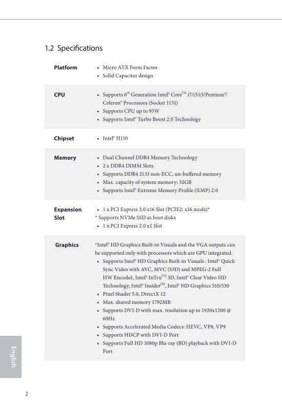
1.2 Specifications
Platform • Micro ATX Form Factor• Solid Capacitor design
CPU • Supports 6th Generation Intel® CoreTM i7/i5/i3/Pentium®/Celeron® Processors (Socket 1151)
• Supports CPU up to 95W • Supports Intel® Turbo Boost 2.0 Technology
Chipset • Intel® H110
Memory • Dual Channel DDR4 Memory Technology• 2 x DDR4 DIMM Slots• Supports DDR4 2133 non-ECC, un-buffered memory • Max. capacity of system memory: 32GB• Supports Intel® Extreme Memory Profile (XMP) 2.0
Expansion Slot
• 1 x PCI Express 3.0 x16 Slot (PCIE2: x16 mode)** Supports NVMe SSD as boot disks• 1 x PCI Express 2.0 x1 Slot
Graphics *Intel® HD Graphics Built-in Visuals and the VGA outputs can be supported only with processors which are GPU integrated. • Supports Intel® HD Graphics Built-in Visuals : Intel® Quick
Sync Video with AVC, MVC (S3D) and MPEG-2 Full HW Encode1, Intel® InTruTM 3D, Intel® Clear Video HD Technology, Intel® InsiderTM, Intel® HD Graphics 510/530
• Pixel Shader 5.0, DirectX 12• Max. shared memory 1792MB • Supports DVI-D with max. resolution up to 1920x1200 @
60Hz• Supports Accelerated Media Codecs: HEVC, VP8, VP9• Supports HDCP with DVI-D Port • Supports Full HD 1080p Blu-ray (BD) playback with DVI-D
Port
2 3
Engl
ish
H110M-DGS
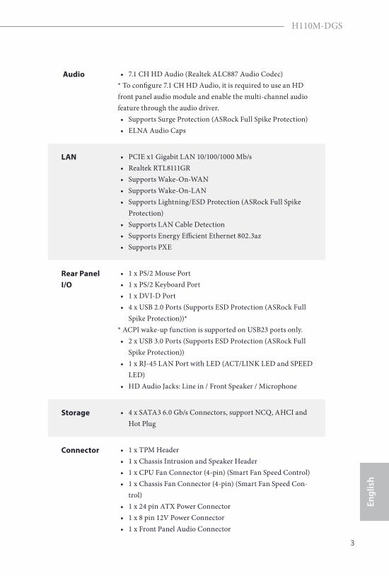
Audio • 7.1 CH HD Audio (Realtek ALC887 Audio Codec) * To configure 7.1 CH HD Audio, it is required to use an HD front panel audio module and enable the multi-channel audio feature through the audio driver.• Supports Surge Protection (ASRock Full Spike Protection)• ELNA Audio Caps
LAN • PCIE x1 Gigabit LAN 10/100/1000 Mb/s• Realtek RTL8111GR• Supports Wake-On-WAN• Supports Wake-On-LAN • Supports Lightning/ESD Protection (ASRock Full Spike
Protection)• Supports LAN Cable Detection• Supports Energy Efficient Ethernet 802.3az• Supports PXE
Rear Panel I/O
• 1 x PS/2 Mouse Port• 1 x PS/2 Keyboard Port• 1 x DVI-D Port• 4 x USB 2.0 Ports (Supports ESD Protection (ASRock Full
Spike Protection))** ACPI wake-up function is supported on USB23 ports only.• 2 x USB 3.0 Ports (Supports ESD Protection (ASRock Full
Spike Protection))• 1 x RJ-45 LAN Port with LED (ACT/LINK LED and SPEED
LED)• HD Audio Jacks: Line in / Front Speaker / Microphone
Storage • 4 x SATA3 6.0 Gb/s Connectors, support NCQ, AHCI and Hot Plug
Connector • 1 x TPM Header• 1 x Chassis Intrusion and Speaker Header• 1 x CPU Fan Connector (4-pin) (Smart Fan Speed Control)• 1 x Chassis Fan Connector (4-pin) (Smart Fan Speed Con-
trol)• 1 x 24 pin ATX Power Connector • 1 x 8 pin 12V Power Connector• 1 x Front Panel Audio Connector
4 5
English
Please realize that there is a certain risk involved with overclocking, including adjusting the setting in the BIOS, applying Untied Overclocking Technology, or using third-party overclocking tools. Overclocking may affect your system’s stability, or even cause damage to the components and devices of your system. It should be done at your own risk and expense. We are not responsible for possible damage caused by overclocking.
* For detailed product information, please visit our website: http://www.asrock.com
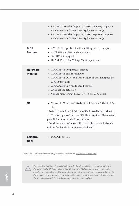
• 1 x USB 2.0 Header (Supports 2 USB 2.0 ports) (Supports ESD Protection (ASRock Full Spike Protection))
• 1 x USB 3.0 Header (Supports 2 USB 3.0 ports) (Supports ESD Protection (ASRock Full Spike Protection))
BIOS Feature
• AMI UEFI Legal BIOS with multilingual GUI support• ACPI 5.0 Compliant wake up events• SMBIOS 2.7 Support• DRAM, PCH 1.0V Voltage Multi-adjustment
Hardware Monitor
• CPU/Chassis temperature sensing• CPU/Chassis Fan Tachometer• CPU/Chassis Quiet Fan (Auto adjust chassis fan speed by
CPU temperature)• CPU/Chassis Fan multi-speed control• CASE OPEN detection• Voltage monitoring: +12V, +5V, +3.3V, CPU Vcore
OS • Microsoft® Windows® 10 64-bit / 8.1 64-bit / 7 32-bit / 7 64-bit
* To install Windows® 7 OS, a modified installation disk with xHCI drivers packed into the ISO file is required. Please refer to page 28 for more detailed instructions.* For the updated Windows® 10 driver, please visit ASRock’s website for details: http://www.asrock.com
Certifica-tions
• FCC, CE, WHQL
4 5
Engl
ish
H110M-DGS
IntelH110
DD
R4
_B
1 (
64
bit
,28
8-p
in m
od
ule
)
DD
R4
_A
1 (
64
bit
, 2
88
-pin
mo
du
le)
CMOSBattery
AT
XP
WR
1
Top:RJ-45
USB 2.0T: USB0B: USB1
USB_4_5
1
HD_AUDIO1
H110M-DGS
RoHS
2
CPU_FAN1
3
5
6
1
BIOSROM
AudioCODEC PCIE2
TPMS1
1
1
US
B3_
3_4
PCIE1
USB 2.0T: USB2B: USB3
To
p:
LIN
E IN
Ce
nte
r:F
RO
NT
Bo
ttom
:M
IC IN
1
ATX12V1
P2
Mo
us
e
16
DV
I1
SA
TA
3_
3
CHA_FAN1
SA
TA
3_
2
SA
TA
3_
1
SA
TA
3_
0
4
7
8
10131415
CLRMOS1
9
USB 3.0T: USB1B: USB2
P2
Ke
yb
oa
rd
SS
HD
LE
D R
ES
ET
PL
ED
P
WR
BT
N
PANEL1
SPK_CI1
1
1112
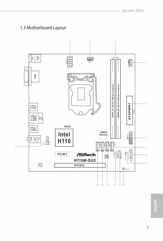
1.3 Motherboard Layout
6 7
English
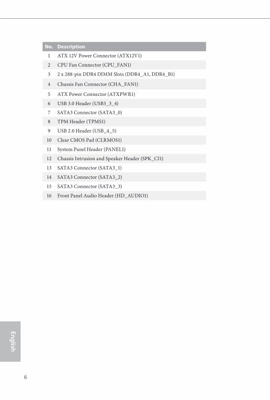
No. Description
1 ATX 12V Power Connector (ATX12V1)
2 CPU Fan Connector (CPU_FAN1)
3 2 x 288-pin DDR4 DIMM Slots (DDR4_A1, DDR4_B1)
4 Chassis Fan Connector (CHA_FAN1)
5 ATX Power Connector (ATXPWR1)
6 USB 3.0 Header (USB3_3_4)
7 SATA3 Connector (SATA3_0)
8 TPM Header (TPMS1)
9 USB 2.0 Header (USB_4_5)
10 Clear CMOS Pad (CLRMOS1)
11 System Panel Header (PANEL1)
12 Chassis Intrusion and Speaker Header (SPK_CI1)
13 SATA3 Connector (SATA3_1)
14 SATA3 Connector (SATA3_2)
15 SATA3 Connector (SATA3_3)
16 Front Panel Audio Header (HD_AUDIO1)
6 7
Engl
ish
H110M-DGS
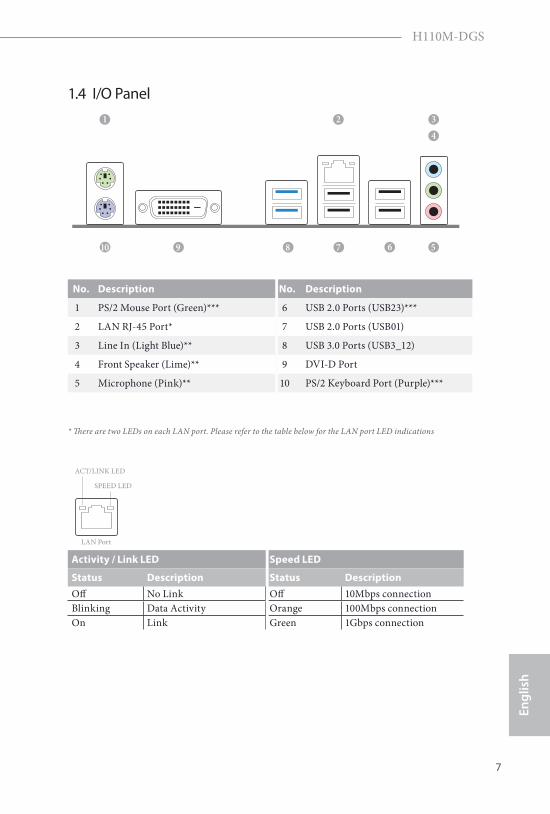
1.4 I/O Panel
No. Description No. Description
1 PS/2 Mouse Port (Green)*** 6 USB 2.0 Ports (USB23)***
2 LAN RJ-45 Port* 7 USB 2.0 Ports (USB01)
3 Line In (Light Blue)** 8 USB 3.0 Ports (USB3_12)
4 Front Speaker (Lime)** 9 DVI-D Port
5 Microphone (Pink)** 10 PS/2 Keyboard Port (Purple)***
5679
243
10
1
8
* There are two LEDs on each LAN port. Please refer to the table below for the LAN port LED indications
Activity / Link LED Speed LED
Status Description Status DescriptionOff No Link Off 10Mbps connectionBlinking Data Activity Orange 100Mbps connectionOn Link Green 1Gbps connection
ACT/LINK LED
SPEED LED
LAN Port
8 9
English
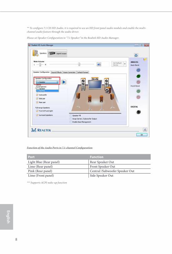
** To configure 7.1 CH HD Audio, it is required to use an HD front panel audio module and enable the multi-channel audio feature through the audio driver.
Please set Speaker Configuration to “7.1 Speaker”in the Realtek HD Audio Manager.
Function of the Audio Ports in 7.1-channel Configuration:
Port FunctionLight Blue (Rear panel) Rear Speaker OutLime (Rear panel) Front Speaker OutPink (Rear panel) Central /Subwoofer Speaker OutLime (Front panel) Side Speaker Out
*** Supports ACPI wake-up function
8 9
Engl
ish
H110M-DGS
This is a Micro ATX form factor motherboard. Before you install the motherboard, study the configuration of your chassis to ensure that the motherboard fits into it.
Pre-installation PrecautionsTake note of the following precautions before you install motherboard components or change any motherboard settings.
• Make sure to unplug the power cord before installing or removing the motherboard components. Failure to do so may cause physical injuries and damages to motherboard components.
• In order to avoid damage from static electricity to the motherboard’s components, NEVER place your motherboard directly on a carpet. Also remember to use a grounded wrist strap or touch a safety grounded object before you handle the components.
• Hold components by the edges and do not touch the ICs.• Whenever you uninstall any components, place them on a grounded anti-static pad or
in the bag that comes with the components.• When placing screws to secure the motherboard to the chassis, please do not over-
tighten the screws! Doing so may damage the motherboard.
Chapter 2 Installation
10 11
English
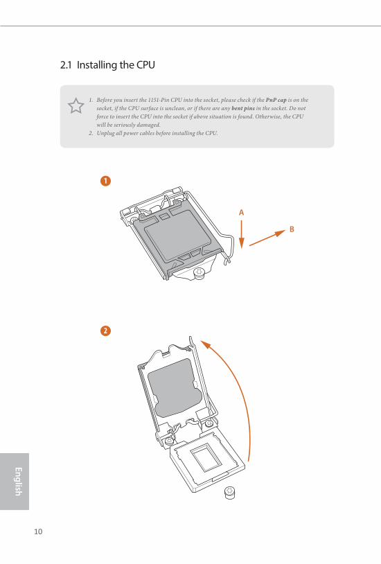
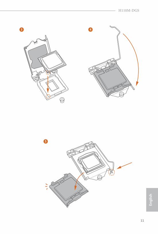
2.1 Installing the CPU
1. Before you insert the 1151-Pin CPU into the socket, please check if the PnP cap is on the socket, if the CPU surface is unclean, or if there are any bent pins in the socket. Do not force to insert the CPU into the socket if above situation is found. Otherwise, the CPU will be seriously damaged.
2. Unplug all power cables before installing the CPU.
1
2
A
B
10 11
Engl
ish
H110M-DGS
4
5
3
12 13
English
Please save and replace the cover if the processor is removed. The cover must be placed if you wish to return the motherboard for after service.
12 13
Engl
ish
H110M-DGS
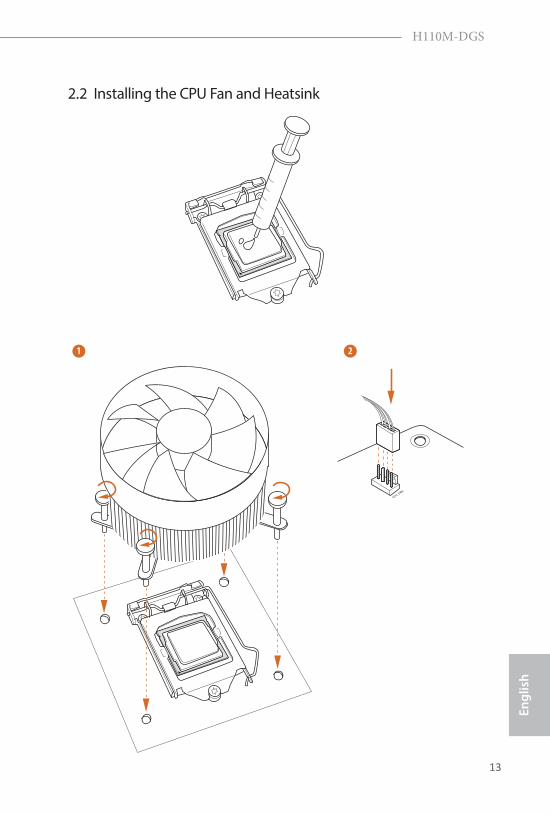
2.2 Installing the CPU Fan and Heatsink
1 2
CPU_FAN
14 15
English
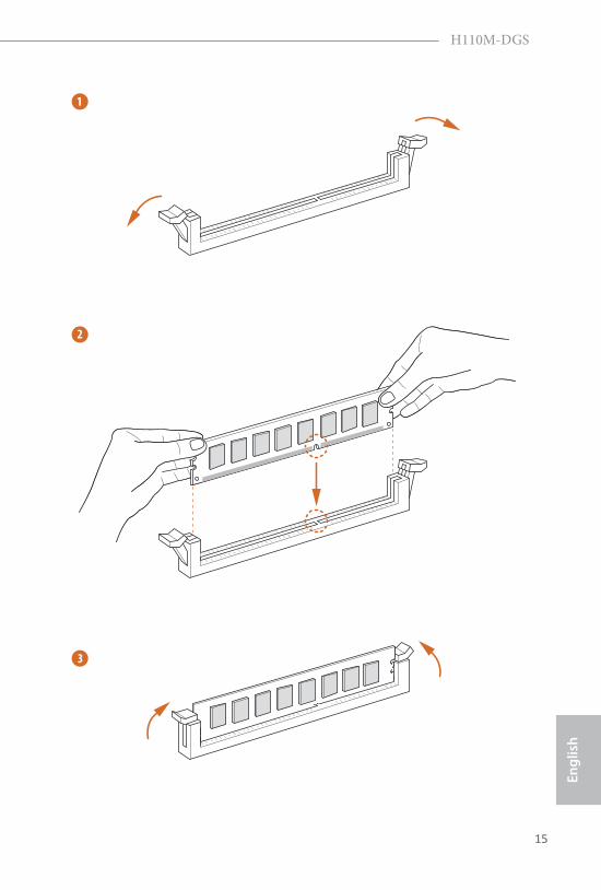
2.3 Installing Memory Modules (DIMM)
This motherboard provides two 288-pin DDR4 (Double Data Rate 4) DIMM slots, and supports Dual Channel Memory Technology.
The DIMM only fits in one correct orientation. It will cause permanent damage to the motherboard and the DIMM if you force the DIMM into the slot at incorrect orientation.
1. For dual channel configuration, you always need to install identical (the same brand, speed, size and chip-type) DDR4 DIMM pairs.
2. It is unable to activate Dual Channel Memory Technology with only one memory module installed.
3. It is not allowed to install a DDR, DDR2 or DDR3 memory module into a DDR4 slot; otherwise, this motherboard and DIMM may be damaged..
14 15
Engl
ish
H110M-DGS
1
2
3
16 17
English
2.4 Expansion Slots (PCI Express Slots)There are 2 PCI Express slots on the motherboard.
PCIe slots:
PCIE1 (PCIe 2.0 x1 slot) is used for PCI Express x1 lane width cards PCIE2 (PCIe 3.0 x16 slot) is used for PCI Express x16 lane width graphics cards.
Before installing an expansion card, please make sure that the power supply is switched off or the power cord is unplugged. Please read the documentation of the expansion card and make necessary hardware settings for the card before you start the installation.
16 17
Engl
ish
H110M-DGS
2.5 Onboard Headers and Connectors
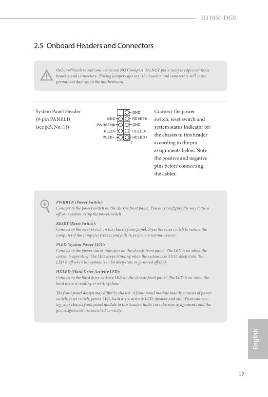
System Panel Header(9-pin PANEL1)(see p.5, No. 11)
Connect the power switch, reset switch and system status indicator on the chassis to this header according to the pin assignments below. Note the positive and negative pins before connecting the cables.
GND RESET#
PWRBTN#
PLED-
PLED+
GND
HDLED-
HDLED+
1
GND
PWRBTN (Power Switch): Connect to the power switch on the chassis front panel. You may configure the way to turn off your system using the power switch.
RESET (Reset Switch): Connect to the reset switch on the chassis front panel. Press the reset switch to restart the computer if the computer freezes and fails to perform a normal restart.
PLED (System Power LED): Connect to the power status indicator on the chassis front panel. The LED is on when the system is operating. The LED keeps blinking when the system is in S1/S3 sleep state. The LED is off when the system is in S4 sleep state or powered off (S5).
HDLED (Hard Drive Activity LED): Connect to the hard drive activity LED on the chassis front panel. The LED is on when the hard drive is reading or writing data.
The front panel design may differ by chassis. A front panel module mainly consists of power switch, reset switch, power LED, hard drive activity LED, speaker and etc. When connect-ing your chassis front panel module to this header, make sure the wire assignments and the pin assignments are matched correctly.
Onboard headers and connectors are NOT jumpers. Do NOT place jumper caps over these headers and connectors. Placing jumper caps over the headers and connectors will cause permanent damage to the motherboard.
18 19
English
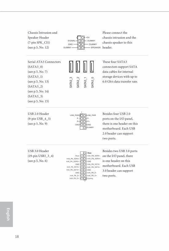
Chassis Intrusion and Speaker Header(7-pin SPK_CI1)(see p.5, No. 12)
Please connect the chassis intrusion and the chassis speaker to this header.
Serial ATA3 Connectors(SATA3_0)(see p.5, No. 7)(SATA3_1)(see p.5, No. 13)(SATA3_2)(see p.5, No. 14)(SATA3_3)(see p.5, No. 15)
These four SATA3 connectors support SATA data cables for internal storage devices with up to 6.0 Gb/s data transfer rate.
USB 2.0 Header(9-pin USB_4_5)(see p.5, No. 9)
DUMMYGND GND
P+
P-
P+
P-
USB_PWRUSB_PWR
1 Besides four USB 2.0 ports on the I/O panel, there is one header on this motherboard. Each USB 2.0 header can support two ports.
USB 3.0 Header(19-pin USB3_3_4)(see p.5, No. 6)
1
IntA_PB_D+
Dummy
IntA_PB_D-
GND
IntA_PB_SSTX+
GND
IntA_PB_SSTX-
IntA_PB_SSRX+
IntA_PB_SSRX-
VbusVbus
Vbus
IntA_PA_SSRX-
IntA_PA_SSRX+
GND
IntA_PA_SSTX-
IntA_PA_SSTX+
GND
IntA_PA_D-
IntA_PA_D+
Besides two USB 3.0 ports on the I/O panel, there is one header on this motherboard. Each USB 3.0 header can support two ports.
1 +5V
DUMMYSIGNAL
GND DUMMY
SPEAKERDUMMY
SATA
3_3
SATA
3_1
SATA
3_2
SATA
3_0
18 19
Engl
ish
H110M-DGS
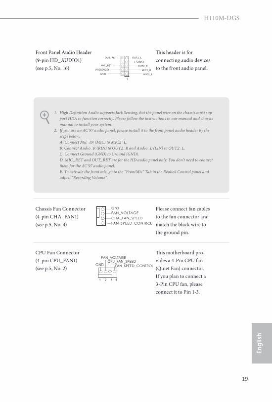
Front Panel Audio Header(9-pin HD_AUDIO1)(see p.5, No. 16)
J_SENSE
OUT2_L
1
MIC_RET
PRESENCE#
GN D
OUT2_R
MIC2_R
MIC2_L
OUT_RET
This header is for connecting audio devices to the front audio panel.
Chassis Fan Connector(4-pin CHA_FAN1)(see p.5, No. 4)
GNDFAN_VOLTAGECHA_FAN_SPEEDFAN_SPEED_CONTROL
Please connect fan cables to the fan connector and match the black wire to the ground pin.
CPU Fan Connector(4-pin CPU_FAN1)(see p.5, No. 2)
GND
FAN_VOLTAGECPU_FAN_SPEED
FAN_SPEED_CONTROL
1 2 3 4
This motherboard pro-vides a 4-Pin CPU fan (Quiet Fan) connector. If you plan to connect a 3-Pin CPU fan, please connect it to Pin 1-3.
1. High Definition Audio supports Jack Sensing, but the panel wire on the chassis must sup-port HDA to function correctly. Please follow the instructions in our manual and chassis manual to install your system.
2. If you use an AC’97 audio panel, please install it to the front panel audio header by the steps below: A. Connect Mic_IN (MIC) to MIC2_L. B. Connect Audio_R (RIN) to OUT2_R and Audio_L (LIN) to OUT2_L. C. Connect Ground (GND) to Ground (GND). D. MIC_RET and OUT_RET are for the HD audio panel only. You don’t need to connect them for the AC’97 audio panel. E. To activate the front mic, go to the “FrontMic” Tab in the Realtek Control panel and adjust “Recording Volume”.
20 21
English
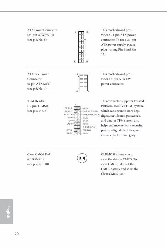
ATX Power Connector(24-pin ATXPWR1)(see p.5, No. 5)
This motherboard pro-vides a 24-pin ATX power connector. To use a 20-pin ATX power supply, please plug it along Pin 1 and Pin 13.
ATX 12V Power Connector(8-pin ATX12V1)(see p.5, No. 1)
5
8
1
4
This motherboard pro-vides a 8-pin ATX 12V power connector.
TPM Header(17-pin TPMS1)(see p.5, No. 8)
1
GND
SMB_DATA_MAIN
LAD2LAD1
GND
S_PWRDWN#SERIRQ#
GND
PCICLK
PCIRST#LAD3
+3VLAD0
+3VSB
GND
FRAME SMB_CLK_MAIN
This connector supports Trusted Platform Module (TPM) system, which can securely store keys, digital certificates, passwords, and data. A TPM system also helps enhance network security, protects digital identities, and ensures platform integrity.
Clear CMOS Pad(CLRMOS1)(see p.5, No. 10)
CLRMOS1 allows you toclear the data in CMOS. Toclear CMOS, take out theCMOS battery and short theClear CMOS Pad.
1
12
13
24
20 21
Engl
ish
H110M-DGS
Chapter 3 Software and Utilities Operation
3.1 Installing DriversThe Support CD that comes with the motherboard contains necessary drivers and useful utilities that enhance the motherboard’s features.
Running The Support CDTo begin using the support CD, insert the CD into your CD-ROM drive. The CD automatically displays the Main Menu if “AUTORUN” is enabled in your computer. If the Main Menu does not appear automatically, locate and double click on the file “ASRSETUP.EXE” in the Support CD to display the menu.
Drivers MenuThe drivers compatible to your system will be auto-detected and listed on the support CD driver page. Please click Install All or follow the order from top to bottom to install those required drivers. Therefore, the drivers you install can work properly.
Utilities MenuThe Utilities Menu shows the application software that the motherboard supports. Click on a specific item then follow the installation wizard to install it.
To improve Windows 7 compatibility, please download and install the following hot fix provided by Microsoft. “KB2720599”: http://support.microsoft.com/kb/2720599/en-us
22 23
English
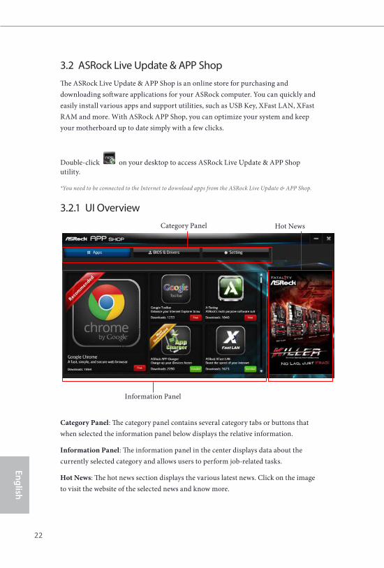
3.2 ASRock Live Update & APP ShopThe ASRock Live Update & APP Shop is an online store for purchasing and downloading software applications for your ASRock computer. You can quickly and easily install various apps and support utilities, such as USB Key, XFast LAN, XFast RAM and more. With ASRock APP Shop, you can optimize your system and keep your motherboard up to date simply with a few clicks.
Double-click on your desktop to access ASRock Live Update & APP Shop utility.
*You need to be connected to the Internet to download apps from the ASRock Live Update & APP Shop.
3.2.1 UI Overview
Category Panel: The category panel contains several category tabs or buttons that when selected the information panel below displays the relative information.
Information Panel: The information panel in the center displays data about the currently selected category and allows users to perform job-related tasks.
Hot News: The hot news section displays the various latest news. Click on the image to visit the website of the selected news and know more.
Information Panel
Hot NewsCategory Panel
22 23
Engl
ish
H110M-DGS
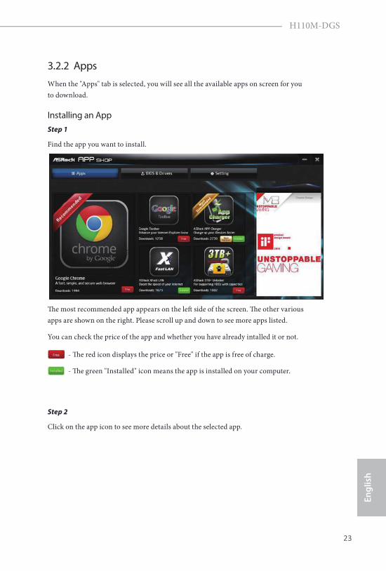
3.2.2 AppsWhen the "Apps" tab is selected, you will see all the available apps on screen for you to download.
Installing an AppStep 1
Find the app you want to install.
Th e most recommended app appears on the left side of the screen. Th e other various apps are shown on the right. Please scroll up and down to see more apps listed.
You can check the price of the app and whether you have already intalled it or not.
- Th e red icon displays the price or "Free" if the app is free of charge.
- Th e green "Installed" icon means the app is installed on your computer.
Step 2
Click on the app icon to see more details about the selected app.
24 25
English
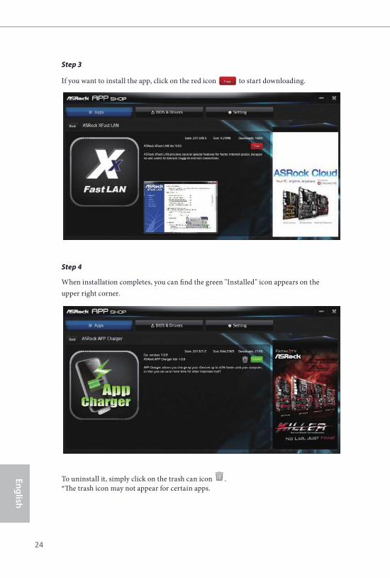
Step 3
If you want to install the app, click on the red icon to start downloading.
Step 4
When installation completes, you can fi nd the green "Installed" icon appears on the upper right corner.
To uninstall it, simply click on the trash can icon . *Th e trash icon may not appear for certain apps.
24 25
Engl
ish
H110M-DGS
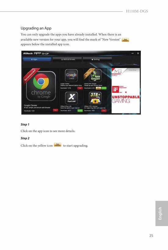
Upgrading an AppYou can only upgrade the apps you have already installed. When there is an available new version for your app, you will fi nd the mark of "New Version" appears below the installed app icon.
Step 1
Click on the app icon to see more details.
Step 2
Click on the yellow icon to start upgrading.
26 27
English
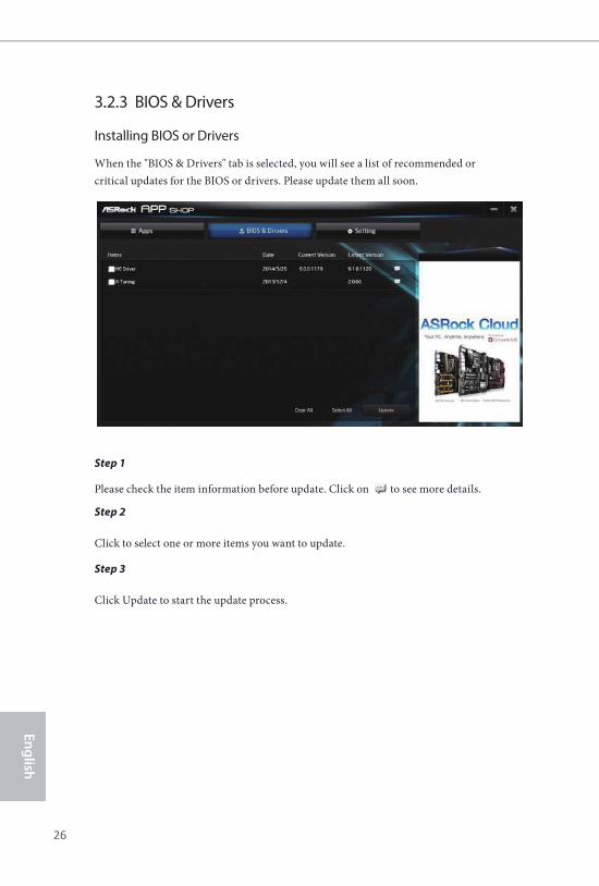
3.2.3 BIOS & Drivers
Installing BIOS or Drivers
When the "BIOS & Drivers" tab is selected, you will see a list of recommended or critical updates for the BIOS or drivers. Please update them all soon.
Step 1
Please check the item information before update. Click on to see more details.
Step 2
Click to select one or more items you want to update.
Step 3
Click Update to start the update process.
26 27
Engl
ish
H110M-DGS
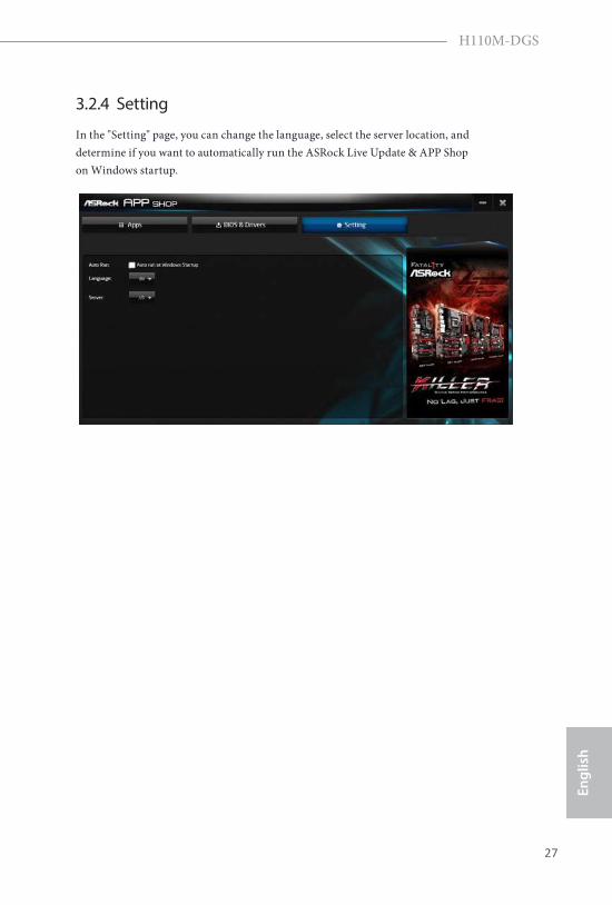
3.2.4 Setting
In the "Setting" page, you can change the language, select the server location, and determine if you want to automatically run the ASRock Live Update & APP Shop on Windows startup.
28 29
English
3.3 Enabling USB Ports for Windows® 7 InstallationIntel® Braswell and Skylake has removed their support for the Enhanced Host Controller Interface (EHCI – USB2.0) and only kept the eXtensible Host Controller Interface (XHCI – USB3.0). Due to that fact that XHCI is not included in the Windows 7 inbox drivers, users may find it difficult to install Windows 7 operating system because the USB ports on their motherboard won’t work. In order for the USB ports to function properly, please create a Windows® 7 installation disk with the Intel® USB 3.0 eXtensible Host Controller (xHCI) drivers packed into the ISO file.
Requirements• A Windows® 7 installation disk or USB drive• USB 3.0 drivers (included in the ASRock Support CD or website)• A Windows® PC • Win7 USB Patcher (included in the ASRock Support CD or website)
Scenarios
You have an ODD and PS/2 ports:
If there is an optical disc drive, PS/2 ports and PS/2 Keyboard or mouse on your computer, you can skip the instructions below and go ahead to install Windows® 7 OS.
You only have an ODD (For Intel Skylake platforms only):
If there is an optical disc drive but no PS/2 ports on your computer, please enable the “PS/2 Simulator” option in UEFI SETUP UTILITY > Advanced > USB Configuration, which allows the USB port to function as a PS/2 port, and then you can install the Windows® 7 OS. Please set PS/2 Simulator back to disabled after the installation.
You’ve got nothing:
If you do not have an optical disc drive, please find another computer and follow the instructions below to create a new ISO file with the “Win7 USB Patcher”. Then use the new patched Windows® 7 installation USB drive to install Windows® 7 OS.
28 29
Engl
ish
H110M-DGS
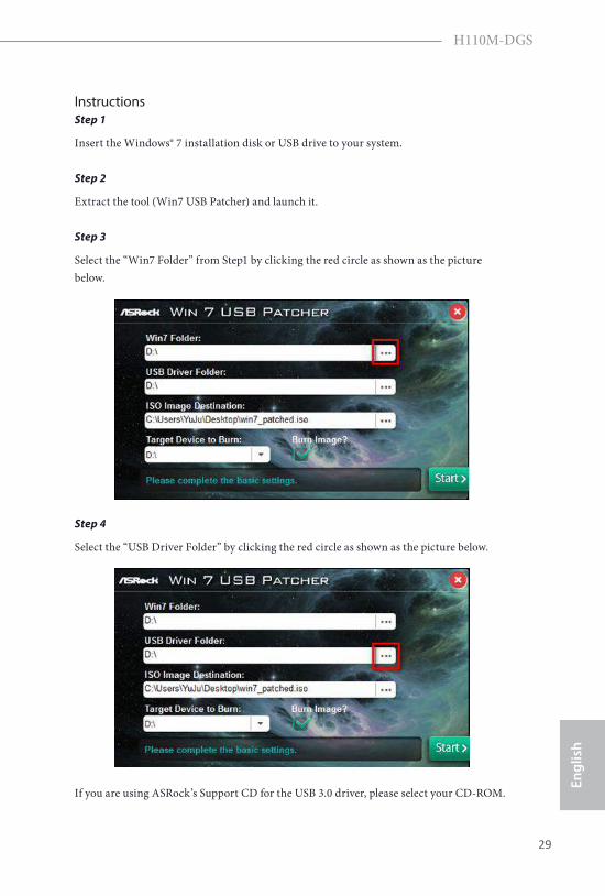
InstructionsStep 1
Insert the Windows® 7 installation disk or USB drive to your system.
Step 2
Extract the tool (Win7 USB Patcher) and launch it.
Step 3
Select the “Win7 Folder” from Step1 by clicking the red circle as shown as the picture below.
Step 4
Select the “USB Driver Folder” by clicking the red circle as shown as the picture below.
If you are using ASRock’s Support CD for the USB 3.0 driver, please select your CD-ROM.
30 31
English
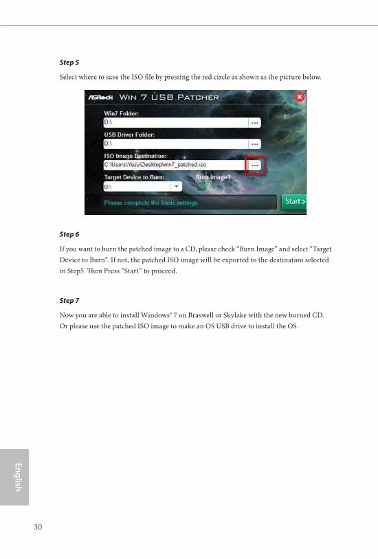
Step 5
Select where to save the ISO file by pressing the red circle as shown as the picture below.
Step 6
If you want to burn the patched image to a CD, please check “Burn Image” and select “Target Device to Burn”. If not, the patched ISO image will be exported to the destination selected in Step5. Then Press “Start” to proceed.
Step 7
Now you are able to install Windows® 7 on Braswell or Skylake with the new burned CD. Or please use the patched ISO image to make an OS USB drive to install the OS.
30 31
Engl
ish
H110M-DGS
Chapter 4 UEFI SETUP UTILITY
4.1 IntroductionThis section explains how to use the UEFI SETUP UTILITY to configure your system. You may run the UEFI SETUP UTILITY by pressing <F2> or <Del> right after you power on the computer, otherwise, the Power-On-Self-Test (POST) will continue with its test routines. If you wish to enter the UEFI SETUP UTILITY after POST, restart the system by pressing <Ctl> + <Alt> + <Delete>, or by pressing the reset button on the system chassis. You may also restart by turning the system off and then back on.
Because the UEFI software is constantly being updated, the following UEFI setup screens and descriptions are for reference purpose only, and they may not exactly match what you see on your screen.
32 33
English
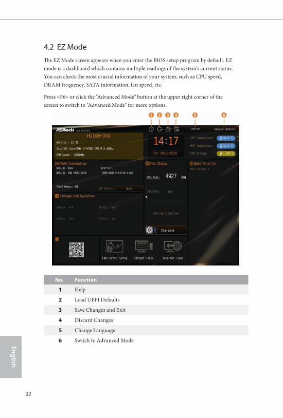
4.2 EZ ModeThe EZ Mode screen appears when you enter the BIOS setup program by default. EZ mode is a dashboard which contains multiple readings of the system’s current status. You can check the most crucial information of your system, such as CPU speed, DRAM frequency, SATA information, fan speed, etc.
Press <F6> or click the "Advanced Mode" button at the upper right corner of the screen to switch to "Advanced Mode" for more options.
No. Function
1 Help
2 Load UEFI Defaults
3 Save Changes and Exit
4 Discard Changes
5 Change Language
6 Switch to Advanced Mode
32 33
Engl
ish
H110M-DGS
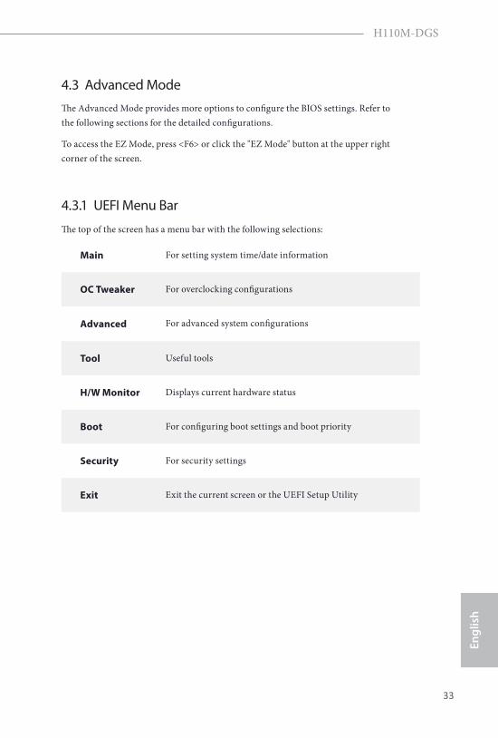
4.3 Advanced ModeThe Advanced Mode provides more options to configure the BIOS settings. Refer to the following sections for the detailed configurations.
To access the EZ Mode, press <F6> or click the "EZ Mode" button at the upper right corner of the screen.
4.3.1 UEFI Menu Bar
The top of the screen has a menu bar with the following selections:
Main For setting system time/date information
OC Tweaker For overclocking configurations
Advanced For advanced system configurations
Tool Useful tools
H/W Monitor Displays current hardware status
Boot For configuring boot settings and boot priority
Security For security settings
Exit Exit the current screen or the UEFI Setup Utility
34 35
English
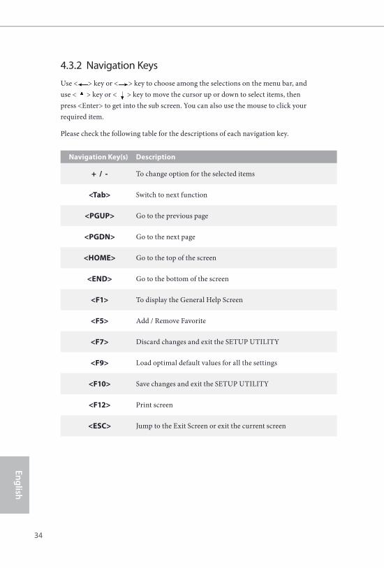
4.3.2 Navigation KeysUse < > key or < > key to choose among the selections on the menu bar, and use < > key or < > key to move the cursor up or down to select items, then press <Enter> to get into the sub screen. You can also use the mouse to click your required item.
Please check the following table for the descriptions of each navigation key.
Navigation Key(s) Description
+ / - To change option for the selected items
<Tab> Switch to next function
<PGUP> Go to the previous page
<PGDN> Go to the next page
<HOME> Go to the top of the screen
<END> Go to the bottom of the screen
<F1> To display the General Help Screen
<F5> Add / Remove Favorite
<F7> Discard changes and exit the SETUP UTILITY
<F9> Load optimal default values for all the settings
<F10> Save changes and exit the SETUP UTILITY
<F12> Print screen
<ESC> Jump to the Exit Screen or exit the current screen
Use < > key or < > key to choose among the selections on the menu bar, and Use < > key or < > key to choose among the selections on the menu bar, and
34 35
Engl
ish
H110M-DGS
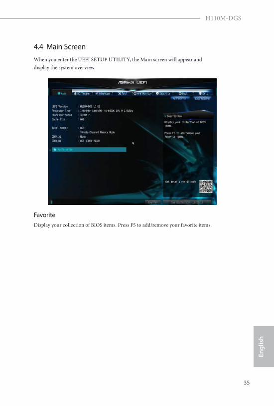
4.4 Main ScreenWhen you enter the UEFI SETUP UTILITY, the Main screen will appear and display the system overview.
FavoriteDisplay your collection of BIOS items. Press F5 to add/remove your favorite items.
36 37
English
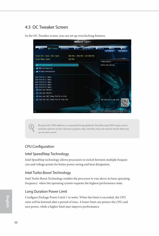
4.5 OC Tweaker Screen
In the OC Tweaker screen, you can set up overclocking features.
CPU Configuration
Intel SpeedStep TechnologyIntel SpeedStep technology allows processors to switch between multiple frequen-cies and voltage points for better power saving and heat dissipation.
Intel Turbo Boost TechnologyIntel Turbo Boost Technology enables the processor to run above its base operating frequency when the operating system requests the highest performance state.
Long Duration Power LimitConfigure Package Power Limit 1 in watts. When the limit is exceeded, the CPU ratio will be lowered after a period of time. A lower limit can protect the CPU and save power, while a higher limit may improve performance.
Because the UEFI software is constantly being updated, the following UEFI setup screens and descriptions are for reference purpose only, and they may not exactly match what you see on your screen.
36 37
Engl
ish
H110M-DGS
Long Duration MaintainedConfigure the period of time until the CPU ratio is lowered when the Long Duration Power Limit is exceeded.
Short Duration Power LimitConfigure Package Power Limit 2 in watts. When the limit is exceeded, the CPU ratio will be lowered immediately. A lower limit can protect the CPU and save power, while a higher limit may improve performance.
DRAM Configuration
DRAM Timing Configuration
Load XMP Setting
Load XMP settings to overclock the DDR4 memory and perform beyond standard specifications.
DRAM Reference ClockSelect Auto for optimized settings.
DRAM FrequencyIf [Auto] is selected, the motherboard will detect the memory module(s) inserted and assign the appropriate frequency automatically.
Primary Timing
CAS# Latency (tCL)
The time between sending a column address to the memory and the beginning of the data in response.
RAS# to CAS# Delay and Row Precharge (tRCDtRP) ORAS# to CAS# Delay : The number of clock cycles required between the opening of a row of memory and accessing columns within it. Row Precharge: The number of clock cycles required between the issuing of the precharge command and opening the next row.
RAS# Active Time (tRAS)
The number of clock cycles required between a bank active command and issuing the precharge command.
38 39
English
Command Rate (CR)
The delay between when a memory chip is selected and when the first active command can be issued.
Secondary Timing
Write Recovery Time (tWR)The amount of delay that must elapse after the completion of a valid write operation, before an active bank can be precharged.
Refresh Cycle Time (tRFC)The number of clocks from a Refresh command until the first Activate command to the same rank.
RAS to RAS Delay (tRRD) The number of clocks between two rows activated in different banks of the same rank.
Write to Read Delay (tWTR)
The number of clocks between the last valid write operation and the next read command to the same internal bank.
Read to Precharge (tRTP)The number of clocks that are inserted between a read command to a row pre-charge command to the same rank.
Four Activate Window (tFAW)The time window in which four activates are allowed the same rank.
CAS Write Latency (tCWL)Configure CAS Write Latency.
Third Timing
tREFIConfigure refresh cycles at an average periodic interval.
tCKEConfigure the period of time the DDR4 initiates a minimum of one refresh command internally once it enters Self-Refresh mode.
38 39
Engl
ish
H110M-DGS
tRDRD_sgConfigure between module read to read delay.
tRDRD_dgConfigure between module read to read delay.
tRDRD_drConfigure between module read to read delay.
tRDRD_ddConfigure between module read to read delay.
tRDWR_sgConfigure between module read to write delay.
tRDWR_dgConfigure between module read to write delay.
tRDWR_drConfigure between module read to write delay.
tRDWR_ddConfigure between module read to write delay.
tWRRD_sgConfigure between module write to read delay.
tWRRD_dgConfigure between module write to read delay.
tWRRD_drConfigure between module write to read delay.
tWRRD_ddConfigure between module write to read delay.
tWRWR_sgConfigure between module write to write delay.
40 41
English
tWRWR_dgConfigure between module write to write delay.
tWRWR_drConfigure between module write to write delay.
tWRWR_ddConfigure between module write to write delay.
RTL Init Value Configure round trip latency init value for round trip latency training.
IO-L Init Value
Configure IO latency init value for IO latency traning.
RTL (CH A) Configure round trip latency for channel A.
RTL (CH B)
Configure round trip latency for channel B.
IO-L (CH A)
Configure IO latency for channel A.
IO-L (CH B) Configure IO latency for channel B.
IO-L Offset (CH A)
Configure IO latency offset for channel A.
IO-L Offset (CH B)
Configure IO latency offset for channel B.
RFR Delay (CH A)
Configure RFR Delay for Channel A.
RFR Delay (CH B)
Configure RFR Delay for Channel B.
40 41
Engl
ish
H110M-DGS
Fourth Timing
twRPREConfigure twRPRE.
Write_Early_ODTConfigure Write_Early_ODT.
tAONPDConfigure tAONPD.
tXPConfigure tXP.
tXPDLLConfigure tXPDLL.
tPRPDENConfigure tPRPDEN.
tRDPDENConfigure tRDPDEN.
twRPDENConfigure twRPDEN.
OREF_RIConfigure OREF_RI.
tREFIx9Configure tREFIx9.
txSDLLConfigure txSDLL.
txs_offsetConfigure txs_offset.
tZQOPERConfigure tZQOPER.
42 43
English
tMODConfigure tMOD.
ZQCS_periodConfigure ZQCS_period.
tZQCSConfigure tZQCS.
Advanced Setting
ODT WR (CH A)Configure the memory on die termination resistors' WR for channel A.
ODT WR (CH B)Configure the memory on die termination resistors' WR for channel B.
ODT PARK (CH A)Configure the memory on die termination resistors' PARK for channel A.
ODT PARK (CH B)Configure the memory on die termination resistors' PARK for channel B.
ODT NOM (CH A)Use this to change ODT (CH A) Auto/Manual settings. The default is [Auto].
ODT NOM (CH B)
Use this to change ODT (CH B) Auto/Manual settings. The default is [Auto].
MRC Fast BootEnable Memory Fast Boot to skip DRAM memory training for booting faster.
Dll Bandwidth 0Configure the Dll Bandwidth 0.
Dll Bandwidth 1Configure the Dll Bandwidth 1.
Dll Bandwidth 2Configure the Dll Bandwidth 2.
42 43
Engl
ish
H110M-DGS
Dll Bandwidth 3Configure the Dll Bandwidth 3.
Margin LimitAdjust Margin Limit to get better memory margin.
Voltage Configuration
DRAM VoltageUse this to configure DRAM Voltage. The default value is [Auto].
PCH VoltageConfigure the chipset voltage (1.0V).
Save User DefaultType a profile name and press enter to save your settings as user default.
Load User DefaultLoad previously saved user defaults.
Save User UEFI Setup Profile to DiskSave current UEFI settings as an user default profile to disk.
Load User UEFI Setup Profile from DiskLoad previously saved user defaults from the disk.
44 45
English
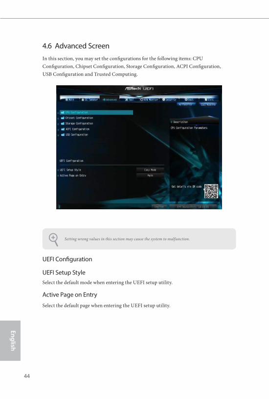
4.6 Advanced ScreenIn this section, you may set the configurations for the following items: CPU Configuration, Chipset Configuration, Storage Configuration, ACPI Configuration, USB Configuration and Trusted Computing.
UEFI Configuration
UEFI Setup StyleSelect the default mode when entering the UEFI setup utility.
Active Page on Entry
Select the default page when entering the UEFI setup utility.
Setting wrong values in this section may cause the system to malfunction.
44 45
Engl
ish
H110M-DGS
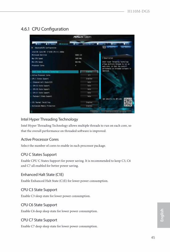
4.6.1 CPU Configuration
Intel Hyper Threading TechnologyIntel Hyper Threading Technology allows multiple threads to run on each core, so that the overall performance on threaded software is improved.
Active Processor CoresSelect the number of cores to enable in each processor package.
CPU C States SupportEnable CPU C States Support for power saving. It is recommended to keep C3, C6 and C7 all enabled for better power saving.
Enhanced Halt State (C1E)Enable Enhanced Halt State (C1E) for lower power consumption.
CPU C3 State SupportEnable C3 sleep state for lower power consumption.
CPU C6 State SupportEnable C6 deep sleep state for lower power consumption.
CPU C7 State SupportEnable C7 deep sleep state for lower power consumption.
46 47
English
Package C State Support
Enable CPU, PCIe, Memory, Graphics C State Support for power saving.
CPU Thermal ThrottlingEnable CPU internal thermal control mechanisms to keep the CPU from overheat-ing.
No-Execute Memory ProtectionProcessors with No-Execution Memory Protection Technology may prevent certain classes of malicious buffer overflow attacks.
Intel Virtualization TechnologyIntel Virtualization Technology allows a platform to run multiple operating systems and applications in independent partitions, so that one computer system can function as multiple virtual systems.
Hardware PrefetcherAutomatically prefetch data and code for the processor. Enable for better performance.
Adjacent Cache Line PrefetchAutomatically prefetch the subsequent cache line while retrieving the currently requested cache line. Enable for better performance.
46 47
Engl
ish
H110M-DGS
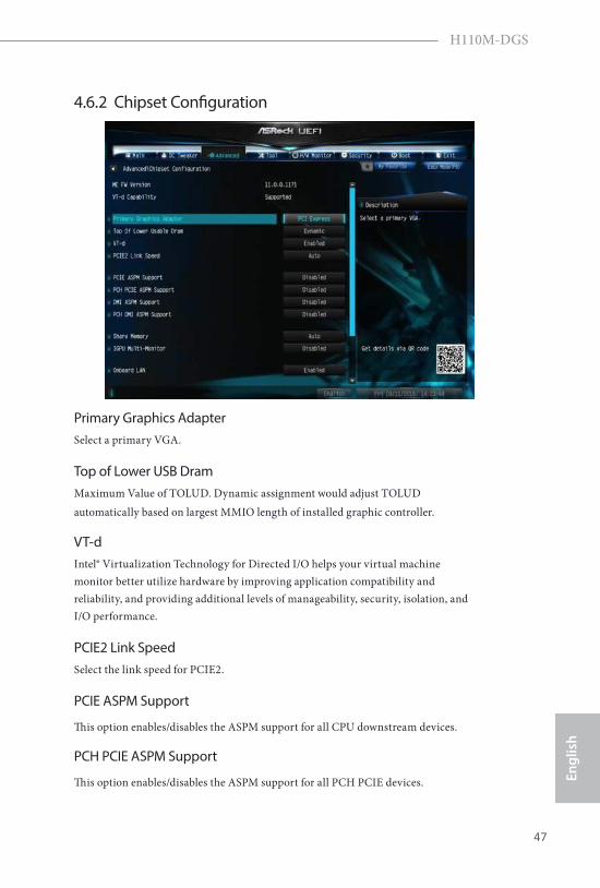
4.6.2 Chipset Configuration
Primary Graphics Adapter Select a primary VGA.
Top of Lower USB DramMaximum Value of TOLUD. Dynamic assignment would adjust TOLUD automatically based on largest MMIO length of installed graphic controller.
VT-dIntel® Virtualization Technology for Directed I/O helps your virtual machine monitor better utilize hardware by improving application compatibility and reliability, and providing additional levels of manageability, security, isolation, and I/O performance.
PCIE2 Link SpeedSelect the link speed for PCIE2.
PCIE ASPM Support
This option enables/disables the ASPM support for all CPU downstream devices.
PCH PCIE ASPM Support
This option enables/disables the ASPM support for all PCH PCIE devices.
48 49
English
DMI ASPM Support
This option enables/disables the control of ASPM on CPU side of the DMI Link.
PCH DMI ASPM Support
This option enables/disables the ASPM support for all PCH DMI devices.
Share Memory
Configure the size of memory that is allocated to the integrated graphics processor when the system boots up.
IGPU Multi-Monitor
Select disable to disable the integrated graphics when an external graphics card is installed. Select enable to keep the integrated graphics enabled at all times.
Onboard LAN
Enable or disable the onboard network interface controller.
Onboard HD AudioEnable/disable onboard HD audio. Set to Auto to enable onboard HD audio and automatically disable it when a sound card is installed.
Front PanelEnable/disable front panel HD audio.
Restore on AC/Power LossSelect the power state after a power failure. If [Power Off] is selected, the power will remain off when the power recovers. If [Power On] is selected, the system will start to boot up when the power recovers.
48 49
Engl
ish
H110M-DGS
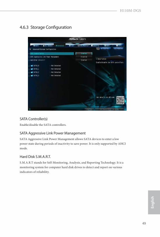
4.6.3 Storage Configuration
SATA Controller(s)Enable/disable the SATA controllers.
SATA Aggressive Link Power ManagementSATA Aggressive Link Power Management allows SATA devices to enter a low power state during periods of inactivity to save power. It is only supported by AHCI mode.
Hard Disk S.M.A.R.T. S.M.A.R.T stands for Self-Monitoring, Analysis, and Reporting Technology. It is a monitoring system for computer hard disk drives to detect and report on various indicators of reliability.
50 51
English
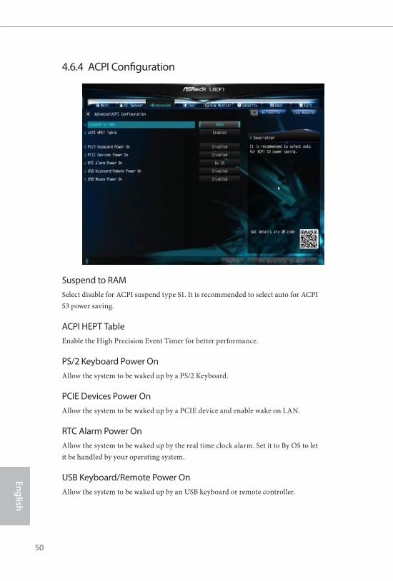
4.6.4 ACPI Configuration
Suspend to RAMSelect disable for ACPI suspend type S1. It is recommended to select auto for ACPI S3 power saving.
ACPI HEPT TableEnable the High Precision Event Timer for better performance.
PS/2 Keyboard Power OnAllow the system to be waked up by a PS/2 Keyboard.
PCIE Devices Power OnAllow the system to be waked up by a PCIE device and enable wake on LAN.
RTC Alarm Power OnAllow the system to be waked up by the real time clock alarm. Set it to By OS to let it be handled by your operating system.
USB Keyboard/Remote Power OnAllow the system to be waked up by an USB keyboard or remote controller.
50 51
Engl
ish
H110M-DGS
USB Mouse Power OnAllow the system to be waked up by an USB mouse.
52 53
English
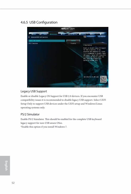
4.6.5 USB Configuration
Legacy USB SupportEnable or disable Legacy OS Support for USB 2.0 devices. If you encounter USB compatibility issues it is recommended to disable legacy USB support. Select UEFI Setup Only to support USB devices under the UEFI setup and Windows/Linux operating systems only.
PS/2 Simulator Enable PS/2 Simulator. This should be enabled for the complete USB keyboard legacy support for non-USB aware OSes. *Enable this option if you install Windows 7.
52 53
Engl
ish
H110M-DGS
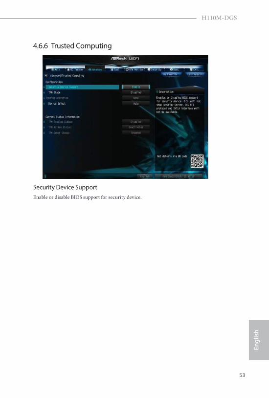
4.6.6 Trusted Computing
Security Device SupportEnable or disable BIOS support for security device.
54 55
English
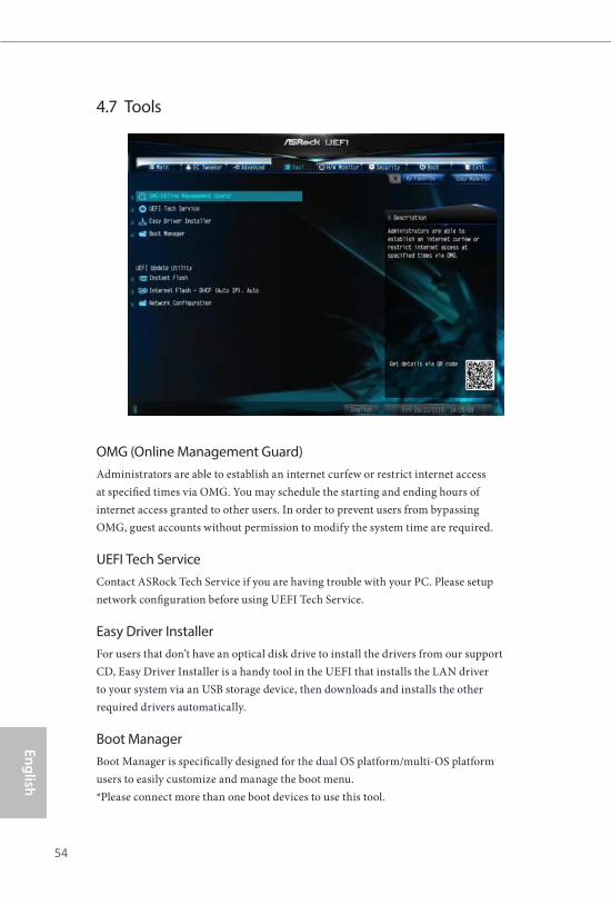
4.7 Tools
OMG (Online Management Guard)Administrators are able to establish an internet curfew or restrict internet access at specified times via OMG. You may schedule the starting and ending hours of internet access granted to other users. In order to prevent users from bypassing OMG, guest accounts without permission to modify the system time are required.
UEFI Tech ServiceContact ASRock Tech Service if you are having trouble with your PC. Please setup network configuration before using UEFI Tech Service.
Easy Driver InstallerFor users that don’t have an optical disk drive to install the drivers from our support CD, Easy Driver Installer is a handy tool in the UEFI that installs the LAN driver to your system via an USB storage device, then downloads and installs the other required drivers automatically.
Boot ManagerBoot Manager is specifically designed for the dual OS platform/multi-OS platform users to easily customize and manage the boot menu. *Please connect more than one boot devices to use this tool.
54 55
Engl
ish
H110M-DGS
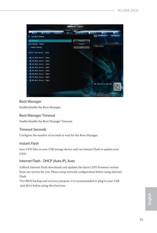
Boot ManagerEnable/disable the Boot Manager.
Boot Manager TimeoutEnable/disable the Boot Manager Timeout.
Timeout SecondsConfigure the number of seconds to wait for the Boot Manager.
Instant FlashSave UEFI files in your USB storage device and run Instant Flash to update your UEFI.
Internet Flash - DHCP (Auto IP), Auto
ASRock Internet Flash downloads and updates the latest UEFI firmware version from our servers for you. Please setup network configuration before using Internet Flash. *For BIOS backup and recovery purpose, it is recommended to plug in your USB pen drive before using this function.
56 57
English
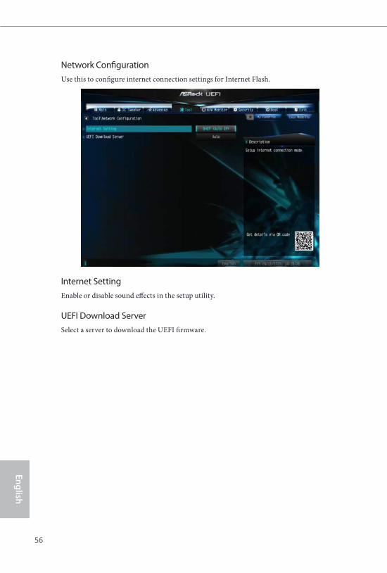
Network ConfigurationUse this to configure internet connection settings for Internet Flash.
Internet SettingEnable or disable sound effects in the setup utility.
UEFI Download ServerSelect a server to download the UEFI firmware.
56 57
Engl
ish
H110M-DGS
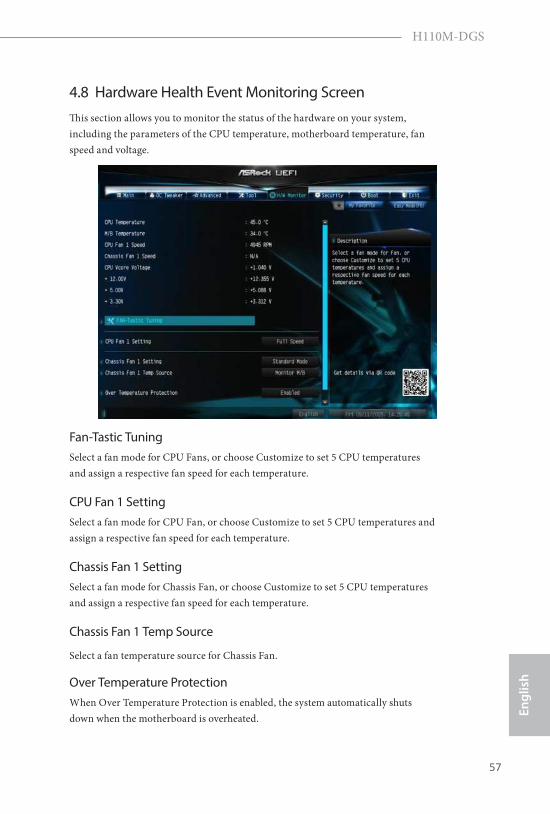
4.8 Hardware Health Event Monitoring ScreenThis section allows you to monitor the status of the hardware on your system, including the parameters of the CPU temperature, motherboard temperature, fan speed and voltage.
Fan-Tastic TuningSelect a fan mode for CPU Fans, or choose Customize to set 5 CPU temperatures and assign a respective fan speed for each temperature.
CPU Fan 1 SettingSelect a fan mode for CPU Fan, or choose Customize to set 5 CPU temperatures and assign a respective fan speed for each temperature.
Chassis Fan 1 SettingSelect a fan mode for Chassis Fan, or choose Customize to set 5 CPU temperatures and assign a respective fan speed for each temperature.
Chassis Fan 1 Temp Source
Select a fan temperature source for Chassis Fan.
Over Temperature ProtectionWhen Over Temperature Protection is enabled, the system automatically shuts down when the motherboard is overheated.
58 59
English
Case Open FeatureEnable or disable Case Open Feature to detect whether the chassis cover has been removed.
58 59
Engl
ish
H110M-DGS
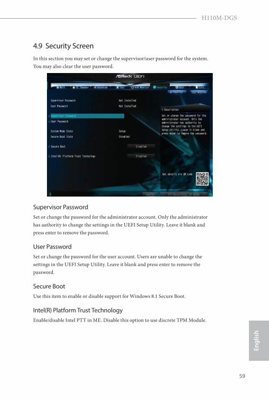
4.9 Security ScreenIn this section you may set or change the supervisor/user password for the system. You may also clear the user password.
Supervisor PasswordSet or change the password for the administrator account. Only the administrator has authority to change the settings in the UEFI Setup Utility. Leave it blank and press enter to remove the password.
User PasswordSet or change the password for the user account. Users are unable to change the settings in the UEFI Setup Utility. Leave it blank and press enter to remove the password.
Secure BootUse this item to enable or disable support for Windows 8.1 Secure Boot.
Intel(R) Platform Trust TechnologyEnable/disable Intel PTT in ME. Disable this option to use discrete TPM Module.
60 61
English
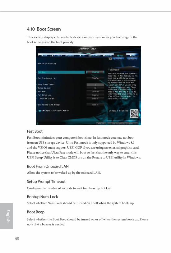
4.10 Boot ScreenThis section displays the available devices on your system for you to configure the boot settings and the boot priority.
Fast BootFast Boot minimizes your computer's boot time. In fast mode you may not boot from an USB storage device. Ultra Fast mode is only supported by Windows 8.1 and the VBIOS must support UEFI GOP if you are using an external graphics card. Please notice that Ultra Fast mode will boot so fast that the only way to enter this UEFI Setup Utility is to Clear CMOS or run the Restart to UEFI utility in Windows.
Boot From Onboard LANAllow the system to be waked up by the onboard LAN.
Setup Prompt Timeout
Configure the number of seconds to wait for the setup hot key.
Bootup Num-LockSelect whether Num Lock should be turned on or off when the system boots up.
Boot Beep
Select whether the Boot Beep should be turned on or off when the system boots up. Please note that a buzzer is needed.
60 61
Engl
ish
H110M-DGS
Full Screen LogoEnable to display the boot logo or disable to show normal POST messages.
AddOn ROM DisplayEnable AddOn ROM Display to see the AddOn ROM messages or configure the AddOn ROM if you've enabled Full Screen Logo. Disable for faster boot speed.
Boot Failure GuardIf the computer fails to boot for a number of times the system automatically restores the default settings.
Boot Failure Guard CountConfigure the number of attempts to boot until the system automatically restores the default settings.
62 63
English
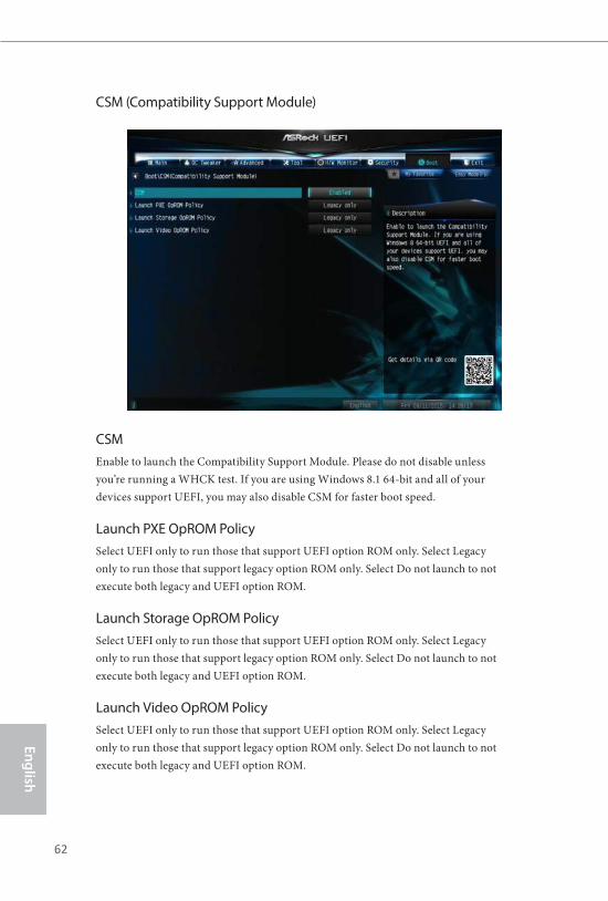
CSM (Compatibility Support Module)
CSM Enable to launch the Compatibility Support Module. Please do not disable unless you’re running a WHCK test. If you are using Windows 8.1 64-bit and all of your devices support UEFI, you may also disable CSM for faster boot speed.
Launch PXE OpROM Policy Select UEFI only to run those that support UEFI option ROM only. Select Legacy only to run those that support legacy option ROM only. Select Do not launch to not execute both legacy and UEFI option ROM.
Launch Storage OpROM PolicySelect UEFI only to run those that support UEFI option ROM only. Select Legacy only to run those that support legacy option ROM only. Select Do not launch to not execute both legacy and UEFI option ROM.
Launch Video OpROM Policy Select UEFI only to run those that support UEFI option ROM only. Select Legacy only to run those that support legacy option ROM only. Select Do not launch to not execute both legacy and UEFI option ROM.
62 63
Engl
ish
H110M-DGS
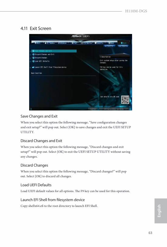
4.11 Exit Screen
Save Changes and ExitWhen you select this option the following message, “Save configuration changes and exit setup?” will pop out. Select [OK] to save changes and exit the UEFI SETUP UTILITY.
Discard Changes and ExitWhen you select this option the following message, “Discard changes and exit setup?” will pop out. Select [OK] to exit the UEFI SETUP UTILITY without saving any changes.
Discard ChangesWhen you select this option the following message, “Discard changes?” will pop out. Select [OK] to discard all changes.
Load UEFI DefaultsLoad UEFI default values for all options. The F9 key can be used for this operation.
Launch EFI Shell from filesystem deviceCopy shellx64.efi to the root directory to launch EFI Shell.
Contact Information
If you need to contact ASRock or want to know more about ASRock, you’re welcome to visit ASRock’s website at http://www.asrock.com; or you may contact your dealer for further information. For technical questions, please submit a support request form at http://www.asrock.com/support/tsd.asp
ASRock Incorporation2F., No.37, Sec. 2, Jhongyang S. Rd., Beitou District,
Taipei City 112, Taiwan (R.O.C.)
ASRock EUROPE B.V.Bijsterhuizen 11-11
6546 AR Nijmegen
The Netherlands
Phone: +31-24-345-44-33
Fax: +31-24-345-44-38
ASRock America, Inc.13848 Magnolia Ave, Chino, CA91710
U.S.A.
Phone: +1-909-590-8308
Fax: +1-909-590-1026