Embed Size (px)
Citation preview

H-Plane Sectoral Horn Antennas in Substrate-Integrated
Waveguide Technology
Guilherme Coelho Gracio [email protected]
Instituto Superior Tecnico, Lisboa, Portugal
November 2017
Abstract
This dissertation aims to study, design and manufacture substrate-integrated waveguide (SIW) H-plane sectoral horn antennas to be used as standard gain antennas in Instituto de Telecomunicacoes /Instituto Superior Tecnico and enhance the existing standard gain antennas collection. In this context,the SIW technology allows to build horns much lighter and as robust as the standard gain pyramidalhorns. Moreover, this technology allows to design compact planar structures. In order to fulfill theseobjectives, one pair of SIW H-plane horns have been designed and manufactured. This pair of antennashave a gain of about 10 dBi in the microwaves L-band. A coaxial-to-waveguide transition have beenintegrated in the prototypes. The design and the free space simulations were performed using the CSTMWS software. After manufacturing the antennas, its performance was measured using an anechoicchamber and a vector network analyzer, and thus allowing a comparison of experimental and simulatedresults. A good agreement has been obtained.
Keywords: H-plane sectoral horn antenna, Substrate-integrated waveguide (SIW), Standard gainantenna, Coaxial-to-waveguide transition, L-band
1. IntroductionAntennas are essential elements of any wireless com-munication system. This element allow for thetransfer of a signal in a wired system to electro-magnetic waves that propagate through free spaceand can be received by another antenna responsi-ble for the reciprocal process of transforming a waveinto a signal that can be processed. The antennacharacteristics required to provide a good perfor-mance depend strongly on the specific system andapplication.
Measuring the radiation pattern and gain of pro-totypes in an anechoic chamber is a meticulous pro-cess. This process is usually made by the use ofstandard gain antennas that receive radiation from(or transmit radiation to) the antenna under test(AUT). Standard gain antennas are used for gainreference and antenna measurements. These anten-nas have their characteristics well defined and whencomparing its results with the results of the AUT,it is possible to take conclusions about its charac-teristics. The most common type of standard gainantenna is the horn.
At Instituto de Telecomunicacoes / Instituto Su-perior (IST) in the anechoic chamber facility thereare a number of standard gain horns covering mostof the range of microwaves. The covered range
starts at 1.72 GHz up to 75.8 GHz and it is dividedby smaller bands according to the EIA standard-WR waveguide system, with each band having apair of antennas. These antennas are pyramidalhorns. It is important to note that the IT/IST hasonly one antenna in the L band, below the lowestband covered by a pair of existing horns. This lasthorn is very large, taking considerable dimensionsand weight.
It is also important to say that this anechoicchamber is designed to have an operation frequencyabove 2 GHz. Studying antennas in this chamberbelow the certified frequency is also possible butthe chamber have more reflections, and thereforethe results are less accurate. However, results withacceptable accuracy can be obtained below 2 GHz.Taking this in consideration, adding the fact thatthe L-band horn is heavy and large, constitute tworeasons which why the IT/IST acquired only onehorn in this band.
To minimize the possibility of reflections on thewalls of the chamber, it is required that the gainof the antenna is as large as possible resulting ina narrower beamdwidth. To achieve large gains,the antennas have to be electrically large. In theanechoic chamber specifications, the antennas haveto be in the farfield of each other to achieve accurate
1
results. The distance between the two positioners isapproximately 5 meters. One of the rules of farfieldthat has to be respected is
d ≥ 2D2
λ(1)
where D is the largest physical linear dimensionof the antenna and λ is the wavelength of the ra-dio wave. For this reason, the standard gain horncan not be electrically large. There is a trade-off between these incompatible requirements, largeand small dimensions and a compromise has to beachieved. A good compromise corresponds to hornwith a gain of about 10 dB. In summary the ob-jectives of this thesis is to design, fabricate and testone pair of SIW H-plane horns to be used in the fre-quency ranges 1.12-1.73 GHz. These antennas needto be as small and light weight as possible, providea gain of about 10 dBi and linear polarization inthe principal E and H planes.
In this context, the substrate-integrated waveg-uide (SIW) technology allows to build horns of ac-ceptable weight and as robust as the pyramidalhorns and our goal is to manufacture one pair ofstandard gain horns in order to enhance the exist-ing collection.
2. State of The Art
2.1. Horns in Free Space
The horn is a waveguide which has been flared toa larger opening. The type, direction and the flareangle can have a big effect on the overall perfor-mance of the element as a radiator. The varietyof shapes and sizes is connected to many practi-cal applications such from communication systems,electromagnetic sensing, radio frequency heating,testing and evaluation, biomedicine, and a refer-ence source for other antenna testing. Sectoral andpyramidal horn antennas are associated with rect-angular waveguides, where the fundamental modeis the TE10, while circular waveguides feed conicalhorns and the fundamental mode is the TE11. [1]
An electromagnetic horn can take many differentforms, four of them are shown in figure 1. Probablythe most commonly occurring horn is the rectangu-lar pyramidal family (figure 1c). A special case issectoral horns, which are flared in only one planeand thus radiating a broad beam in the plane or-thogonal to the flare. The conical horn allows anypolarization of the exciting dominant TE11 modeand it is well-suited for circular polarization.
Flaring a waveguide provides a directive radia-tion pattern and a smooth transition from the in-put to free space. The surface across the face ofthe horn is called the aperture and is a referencefor calculating the radiated fields. For horns with
Figure 1: Different configurations of electromag-netic horn antennas [1]
aperture dimensions greater than about one wave-length, the radiation characteristics may be calcu-lated with reasonable accuracy by using equivalentcurrents (equivalence principle) and an approxima-tion to the aperture field [2].
2.2. H-Plane Horn Antennas
The H-plane sectoral horn is one whose opening isflared in the direction of the H-field while keepingthe other constant, and its shown in figure 2a. Thehorn is fed from a rectangular waveguide of interiordimensions a and b, with a the broad wall dimen-sion. The aperture is of width a1 in the H-plane andheight b1=b in the E-plane. The H-plane cross sec-tion in figure 2b reveals the geometrical parameters.In figure 3 it is represented the spherical coordinatesystem used and in grey is drawn the aperture ofthe horn included in the plane xy = 0. The dimen-sions a1 and Lh (or ρh or ρ2) must be determinedto allow construction of the horn.
2.2.1 Radiated Fields
Huygen’s equivalent principle can be applied to theaperture across the opening to obtain equivalentcurrent on the aperture, and then farfield region andelectric vector potential can be achieved by integrat-ing equivalent aperture magnetic and electric cur-rents over the aperture. Assume aperture fields areassociated with transverse electric fields of waveg-uide through a quadratic phase item, and substitutethis relationship into magnetic vector potential andelectric vector potential result in a two-dimensionalFourier transform. Farfield electric field and mag-netic field can be now obtained. The horn antennapattern on E-plane and H-plane can be computedfrom [3].
2.2.2 Directivity
The maximum radiation is directed nearly along thez-axis (θ = 0◦) and the directivity for the H-plane
2
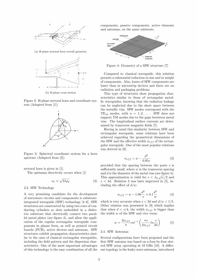
(a) H-plane sectoral horn overall geometry
(b) H-plane cross section
Figure 2: H-plane sectoral horn and coordinate sys-tem (Adapted from [1])
Figure 3: Spherical coordinate system for a hornaperture (Adapted from [2])
sectoral horn is given in [1].The optimum directivity occurs when [1]
a1 '√
3λρ2 (2)
2.3. SIW Technology
A very promising candidate for the developmentof microwave circuits and components is substrate-integrated waveguide (SIW) technology [4–6]. SIWstructures are constructed by using two rows of con-ducting cylinders or slots embedded in a dielec-tric substrate that electrically connect two paral-lel metal plates (see figure 4), and allow the appli-cation of the regular rectangular waveguide com-ponents in planar form, as well as printed circuitboards (PCB), active devices and antennas. SIWstructures exhibit propagation characteristics simi-lar to the ones of classical rectangular waveguides,including the field pattern and the dispersion char-acteristics. One of the most important advantagesof this technology is the easy combination of all the
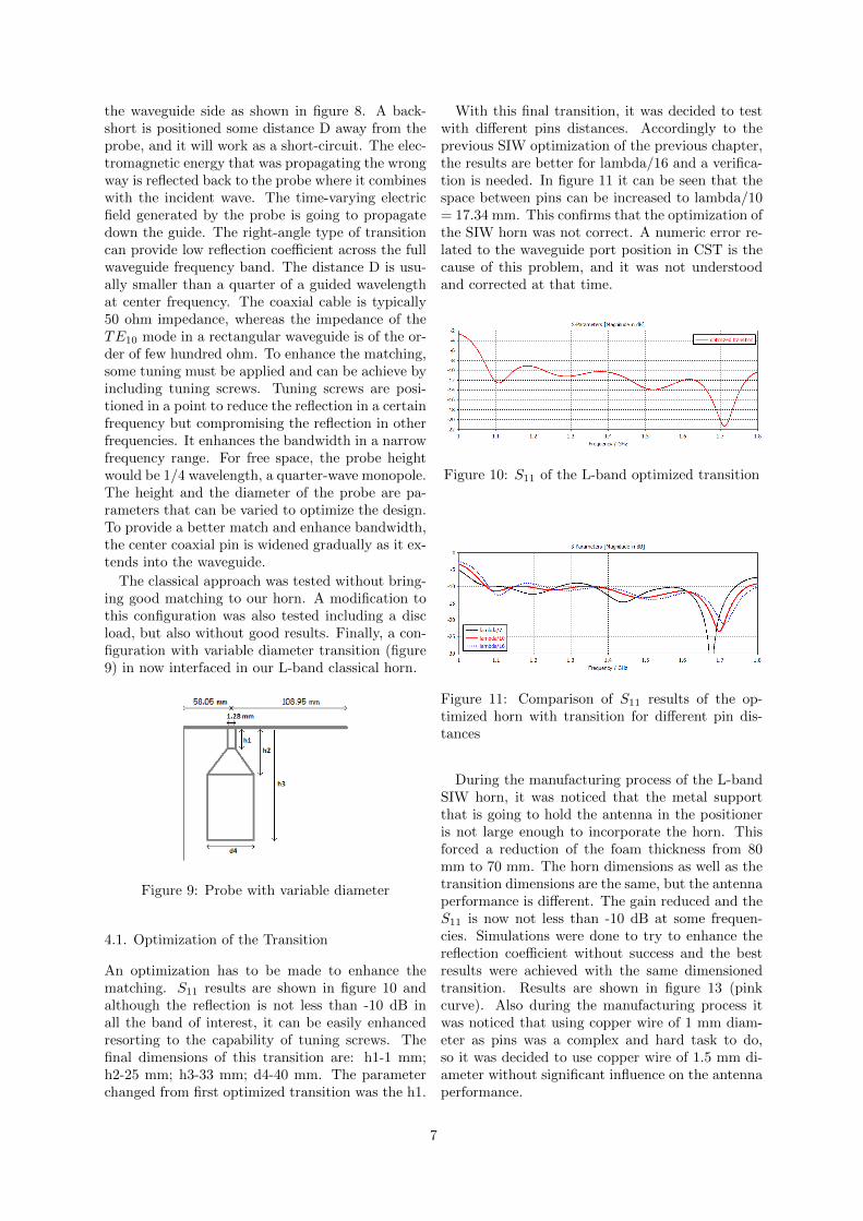
components, passive components, active elementsand antennas, on the same substrate.
Figure 4: Geometry of a SIW structure [7]
Compared to classical waveguide, this solutionpermits a substantial reduction in size and in weightof components. Also, losses of SIW components arelower than in microstrip devices and there are noradiation and packaging problems.
This type of structures show propagation char-acteristics similar to those of rectangular metal-lic waveguides, knowing that the radiation leakagecan be neglected due to the short space betweenthe metallic vias. SIW modes correspond with theTEn0 modes, with n = 1, 2, . . . . SIW does notsupport TM modes due to the gaps beetween metalvias. The longitudinal surface currents are deter-mined by transverse magnetic fields [7].
Having in mind this similarity between SIW andrectangular waveguide, some relations have beenachieved regarding the geometrical dimensions ofthe SIW and the effective width weff of the rectan-gular waveguide. One of the most popular relationswas derived in [8]:
weff = w − d2
0.95s(3)
provided that the spacing between the posts s issufficiently small, where w is the transverse spacingand d is the diameter of the metal vias (see figure 4).This approximation is valid for s < λ0.
√εr/2 and
s < 4d. Relation 3 was later improved in [5], in-cluding the effect of d/w:
weff = w − 1.08d2
s+ 0.1
d2
w(4)
which is very accurate when s < 3d and d/w < 1/5.Other relation was presented in [9] which impliesthat when d < s/4, the width weff is bigger thanthe width w of the SIW and vice versa:
w =2weff
πcot−1
(πs
4weffln
s
2d
)(5)
2.4. SIW Antennas
Several configurations have been proposed and thefirst SIW antenna was based on a four-by-four slot-ted SIW array operating at 10 GHz [10]. A differ-ent topology is the leaky-wave antennas, introduced
3

in [11] and exploits one of the fundamental charac-teristics of the SIW, the property to generate radi-ation leakage when the longitudinal spacing of themetal vias is sufficiently large.
Apart from the classical waveguide-based anten-nas, with apertures either on the top or on the sidewall, other antenna configurations have been pro-posed in the literature. In [12] it is presented amodified Vivaldi radiator that consists of a dual V-type tapered slot antenna which is a good topologyto be integrated in SIW technology. A cavity SIWantenna has been proposed in [13] and consists of aslotted SIW cavity fed by a coplanar waveguide.
Compact, patch oscillator antennas were pro-posed in [14]. It was used a square SIW cavitywhere the antenna was etched on the metal layeron one side of the substrate, and the antenna feednetwork and active device were placed on the otherside, minimising unwanted effects on the radiationpattern of the antenna.
2.4.1 SIW Horns
One of the advantages of combining SIW and hornsis the physical adaptation. This solutions permit areduction in size and weight of components. Thehorns have to be H-plane sectoral horn because ofthe planar requirement to take benefit of the capa-bility of SIW.
Some of the limitations associated to the use ofsubstrate are low efficiency as frequency is increaseddue to dielectric loss, strong mismatch due to theuse of thin substrate layers, high reflection at theend of the aperture caused by the impedance dif-ference between the air and the dielectric, and lowgain.
There are common techniques to improve thehorn performance and to reduce its dimensions, forexample to include a loading or a lens over thehorn aperture, optimized transitions, or includingair vias in the structure. An H-plane sectoral hornantenna in SIW technology is presented in [15].This antenna was also combined with a dielectricloading with rectangular and elliptical shape, inte-grated in the same substrate, which allows high gainand narrow beamwidths both in the E-plane andin the H-plane. Usually, dielectric lenses are usedsince metal-plate lenses introduce a polarizing ef-fect and their edges cause diffraction. This solutionis easy to implement as the lens can be created byextending the same dielectric slab where the hornis built. These horns are known as lens-correctedhorns and the lens focuses the radiation frontwards,increasing the front-to-back-ratio and reducing thephase error. This antenna has been used to forma one-dimensional mono-pulse antenna array to ob-tain higher gain.
Other rectangular dielectric loaded SIW H-planesectoral horn antennas have been fabricated andtested in [16] and resulted in improved gain andbeamwidth. The length of the horn was reducedfurther which resulted in an increase of gain andalso narrow beamwidths in the E-plane and H-plane.
An highly efficient empty substrate-integratedwaveguide H-plane sectoral horn is presented in [17].The antenna is integrated with a planar substrateand is fed by a microstrip line. It is composed ofa partially empty substrate layer stacked betweentwo cover metallic plates. The structure does notdepend on substrate characteristics and this newmethodology improves the performance of conven-tional substrate-integrated waveguide horn anten-nas.
The design rules for SIW horn antennas followthe same principles as free space horn antennas. Toensure the single mode excitation of a H-plane SIWhorn, the width of the feeding waveguide a shouldbe such as λ0/
(2√εr)< a < λ0/
(√εr)
and theheight b smaller than a, and in order to excite thefundamental mode, b can be as small as desired.However, SIW Horns are not well matched whenthe substrate thickness b is much smaller than thefree space wavelength λ0 , and usually the avail-able substrates are much thinner than the wave-length yielding poor matching and undesired backradiation. The previous lens approach presented isnot feasible for h < λ0/10 because of the effect ofthe lens is negligible. In [18], a structure that con-sists of a transition printed in the same SIW sub-strate which improves both the radiation and thematching performances of conventional SIW hornsis presented. The horn shape is further optimizedby reducing its dimensions required for a given di-rectivity and the transition is adapted to improvemore the front-to-back ratio in [19]. The proposedtransition is designed to match a H-plane SIW hornbuilt in a thin substrate (thickness < λ0/10) at theKu-band. In general, for thicknesses smaller thanλ0/6, the mismatch between the aperture and theair results in unwanted radiation and poor match-ing, what is frequently encountered at frequencieslower than 20 GHz. The existing thicker substratethan (h > 2.5) mm are not well suited for manufac-turing SIW structures because the via metalizationis then challenging, and for these reasons the SIWtechnology is mainly used in the millimeter-wave re-gion. The solution proposed is based on a printedtransition etched after the horn aperture, maintain-ing the most important features of the SIW tech-nology, namely its compactness and ease of manu-facturing.
Other technique is to integrate metal rectangu-lar patches and dielectric loading into the aperture
4

of the horn antenna proposed in [20] to a H-planehorn. This results in an increased gain, narrow E-plane beamwidth, and reduced sidelobes and back-ward radiation. To minimize the sidelobes whilemaintaining compact size and easy fabrication, therectangular patches are added in front of both thetop and bottom layers of the dielectric loaded SIWH-plane horn.
Recently, two novel designs of SIW H-plane hornantenna have been presented in [21]. The structureis a transition with double square loop and furtherimproved with rotated double square loop. Thistechnique improves the mismatch between the hornand free space and the bandwidth performance canbe improved to a large extent by optimizing thedimensions of the double square loop and rotationangle.
3. Design of H-Plane SIW Horns
The system is constituted by the aggregation ofthree parts: the waveguide, the horn and the feed.
To ensure the single mode TE10 excitation of aH-plane SIW horn, the dimension of the feedingwaveguide a should respect this requirement.
Basic behavior of a waveguide depends upon thedimensions of the waveguide and the dielectric con-stant. The cutoff frequency for both the TEmn andTMmn modes of a waveguide are given by
fcmn =c
2π√εr
√(mπa
)2+(nπb
)2(6)
The dimension a determines the cutoff frequency ofthe fundamental mode TE10,
a =c0
2fc10√εr
(7)
In order to avoid a high dispersion zone, lowerpower capacity and greater attenuation, the lowestworking frequency of the waveguide is commonlychosen 20% above the cutoff frequency of the fun-damental mode. Higher values of b lead to the lowerattenuation and greater power capacity. However,if b > a/2, the second mode will be TE01 and thefrequency band for unimodal mode is smaller. Forthis reason, normally it is decided that b = a/2 orslightly lower. To avoid leaving the frequency rangeof the unimodal mode, the guide is used of about90% of the cutoff frequency of the second mode.The equation 7 becomes:
a =1.2c0
2fmin√εr
(8)
For a conventional hollow rectangular waveguide,it is considered that εr = 1, and the antenna willoperate in the L band, the minimum frequency ofuse is 1.12 GHz and the cutoff frequency is 933MHz. The dimension a then takes the value of
Table 1: Gain of a FR4 printed SIW horn for dif-ferent number of plates/thicknesses
#Plates Thickness [mm] Gain [dBi]1 1.6 -14.12 3.2 -10.94 6.4 -7.718 12.8 -4.4632 51.2 3.6
160.7 mm. The cutoff frequency of the second mode(2x933MHz = 1.866 GHz) is above the intendedmaximum frequency of use which is 1.73 GHz.
3.1. Metallic H-plane Horn in FR4 Substrate
The FR4 plates physical limitations. The plateshave dimensions 420x350 cm2 and thickness of 1.6mm. It has to be decided to which side the horn isgoing to flare, to the one that is wider or not. Onthis study, it was decided to take 40 mm for thelength of the waveguide and so it gives two optionsof dimensioning the horn: 1)380x350 or 2)420x310.The thickness depends on how many plates are go-ing to be used, having in mind they are going tobe placed on the top of each other. In between theplates, a planar radiating element would be placed.The options are 2 plates together, 4 or 8, knowingthat having 8 plates it is equal to a thickness of 12.8mm, a considerable value of thickness. In table 1 itis presented the gain for different number of platesand the corresponding thicknesses.
The gain is improved when using a thicker sub-strate, which is not suitable for our project. To endthis study of the use of FR4 substrate, it is goingto be calculated the number of plates that would benecessary to have a reasonable gain. With 32 platesof FR4, it gives a thickness of 51.2 mm and a gainof 3.6 dBi is achieved. With a two blocks struc-ture transition and this number of plates, a gainof 7.57 dBi can be achieved. This is an acceptablegain value but the antenna is not feasible due tothe complexity of the process of bonding so manysubstrate plates.
3.2. Metallic H-plane Horn in Foam Substrate
The optimization of a classical metallic horn has tobe made before the design of the SIW structure.Due to the equivalence between the two structures,the metallic structure has to be studied first.
A design has to me made to achieve our require-ments and to respect our limitations. The platesavailable have dimensions 1250x600 mm2 and thick-nesses from 40 mm to 80 mm in intervals of 10 mm.The rule of farfield (equation 1) has also to be re-spected for a 5 meters measurement distance, cor-responding to the distance between positioners in
5

the anechoic chamber. Using the rule, the largestphysical linear dimension of the antenna is 658 mm(for the smaller wavelength). It means that wecan assume that our plate maximal dimensions are658x600 mm2.
Having our physical limitations in mind, and re-specting the reference level of -10 dB for the re-flection coefficient, an optimized horn has been ob-tained from simulations. The LH is 414 mm result-ing in a good reflection coefficient . The dimensionsare presented in figure 6. It is important to statethat at the initial frequency 1.12 GHz the S11 takes-9.37 dB and after 1.13 GHz, the S11 is always be-low -10 dB. The gain is 9.98 dBi and the HPBW is111◦ for the E-plane and 29◦ for the H-plane.
Figure 5: S11 results of the H-plane foam optimizedhorn
Figure 6: CST model and dimensions of the L-bandH-plane metallic horn
3.3. SIW H-plane Horn in Foam Substrate
First of all, a comparison between horn with metal-lic walls and SIW horn has to be made to ensurethat there is a good equivalence between models.The distance between pins in SIW is the same asthe diameter of pins (1 mm) resulting in the designmost similar to a classic metallic horn. As it is ex-pected, the S11 results are very similar and they areshown in figure 7.
The distance between pins is now progressivelyincreased to verify the conclusions taken beforewhen studying the distance between pins on thewaveguide model. The values of s are in wave-lengths and the wavelength is the smaller over therange. It means for the highest frequency, 1.73 GHz
it gives a wavelength of 173.41 mm. For lambda/16,it gives a good S11 over the frequency range, but atfrequency 1.33 GHz, it is slighty above the -10 dBlevel. For lambda/15 the S11 is completely differ-ent. It was concluded that this results are not inconformity with the conclusions taken before for awaveguide study. Before, it was concluded that forvalues of s starting at lambda/6 to smaller values ofspacing that the transmission and reflection in SIWis acceptable.
Figure 7: Comparison of S11 results of classical andSIW models
4. Horns with Coaxial-Waveguide Transition
The rectangular waveguide is a non-TEM modewave propagating structure, where the wave istransmitted in a TE or TM mode. A coaxial linesupports a TEM mode. The coaxial to waveguidetransition converts the TEM mode of the coax-ial line into the TE10 mode of the waveguide andvice-versa. Two classical approaches in designingcoaxial-to-waveguide transitions are the electric (orright-angle) probe and the magnetic (or in-line)probe. To achieve an optimum impedance match,the optimization concerns finding the best location,height and diameter of the probe.
Figure 8: Electric probe coaxial-to-waveguide tran-sition
The most common classical approach of coaxial-to-waveguide transition is the right-angle transi-tion, also known as electric probe. The inner con-ductor of a coaxial cable is incorporated in thewaveguide by using a simple antenna probe reach-ing into the waveguide to excite the TE10 mode,and the shield of the coaxial cable is connected to
6
the waveguide side as shown in figure 8. A back-short is positioned some distance D away from theprobe, and it will work as a short-circuit. The elec-tromagnetic energy that was propagating the wrongway is reflected back to the probe where it combineswith the incident wave. The time-varying electricfield generated by the probe is going to propagatedown the guide. The right-angle type of transitioncan provide low reflection coefficient across the fullwaveguide frequency band. The distance D is usu-ally smaller than a quarter of a guided wavelengthat center frequency. The coaxial cable is typically50 ohm impedance, whereas the impedance of theTE10 mode in a rectangular waveguide is of the or-der of few hundred ohm. To enhance the matching,some tuning must be applied and can be achieve byincluding tuning screws. Tuning screws are posi-tioned in a point to reduce the reflection in a certainfrequency but compromising the reflection in otherfrequencies. It enhances the bandwidth in a narrowfrequency range. For free space, the probe heightwould be 1/4 wavelength, a quarter-wave monopole.The height and the diameter of the probe are pa-rameters that can be varied to optimize the design.To provide a better match and enhance bandwidth,the center coaxial pin is widened gradually as it ex-tends into the waveguide.
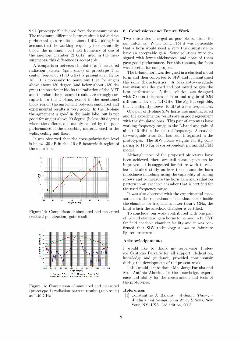
The classical approach was tested without bring-ing good matching to our horn. A modification tothis configuration was also tested including a discload, but also without good results. Finally, a con-figuration with variable diameter transition (figure9) in now interfaced in our L-band classical horn.
Figure 9: Probe with variable diameter
4.1. Optimization of the Transition
An optimization has to be made to enhance thematching. S11 results are shown in figure 10 andalthough the reflection is not less than -10 dB inall the band of interest, it can be easily enhancedresorting to the capability of tuning screws. Thefinal dimensions of this transition are: h1-1 mm;h2-25 mm; h3-33 mm; d4-40 mm. The parameterchanged from first optimized transition was the h1.
With this final transition, it was decided to testwith different pins distances. Accordingly to theprevious SIW optimization of the previous chapter,the results are better for lambda/16 and a verifica-tion is needed. In figure 11 it can be seen that thespace between pins can be increased to lambda/10= 17.34 mm. This confirms that the optimization ofthe SIW horn was not correct. A numeric error re-lated to the waveguide port position in CST is thecause of this problem, and it was not understoodand corrected at that time.
Figure 10: S11 of the L-band optimized transition
Figure 11: Comparison of S11 results of the op-timized horn with transition for different pin dis-tances
During the manufacturing process of the L-bandSIW horn, it was noticed that the metal supportthat is going to hold the antenna in the positioneris not large enough to incorporate the horn. Thisforced a reduction of the foam thickness from 80mm to 70 mm. The horn dimensions as well as thetransition dimensions are the same, but the antennaperformance is different. The gain reduced and theS11 is now not less than -10 dB at some frequen-cies. Simulations were done to try to enhance thereflection coefficient without success and the bestresults were achieved with the same dimensionedtransition. Results are shown in figure 13 (pinkcurve). Also during the manufacturing process itwas noticed that using copper wire of 1 mm diam-eter as pins was a complex and hard task to do,so it was decided to use copper wire of 1.5 mm di-ameter without significant influence on the antennaperformance.
7

5. Prototypes and Experimental Results
5.1. Prototypes
One pair of H-plane SIW horns were produced. Theworking frequency is in L-band. The spacing be-tween pins is equal to lambda/10 = 17.341 mm ofthe highest frequency. Respecting this spacing be-tween pins, for each side of horn, it is need an inte-ger number of pins. It results in a slightly smallerspacing between pins for each side. Referring to ourfinal horn dimensions in figure 6, for a = 165.1 it isneeded 11 pins and it results in s = 16.51 mm. ForL1 = 167 mm, 11 pins are also needed but with s= 16.7 mm. Finally for the flare side equal to 461mm, it is needed 28 pins with s = 17.07 mm. Thetotal number of pins is equal to 85 and it was usedcopper wire of diameter 1.5 mm as a metal pin. Thefoam used is 2 plates of roofmate, one with 30 mmthickness and another of 40 mm, placed together.
It was decided to give a margin of 5 mm in eachside between the pins center and the edge of thecopper plates. The initial plan to build the proto-type was to join the foam as also the copper platestogether and then proceed to weld the pins on bothsides of the antenna. Due to the heat of the weldprocedure, the foam started to melt more than whatwas expected. Because of this problem, it was de-cided to first, weld all pins and after this, incorpo-rate the foam that was cropped exactly to be in-serted from the horn aperture to the bottom. Thehorn with the welded pins and foam can be seen infigure 12a. The transition was inserted inside thefoam and incorporated at the same time the foamwas incorporated. The SMA connector was weldedto the horn top face then joined to the brass transi-tion with a 1.5 mm screw that can be seen in figure12b.
(a) SIW horn with sub-strate
(b) Coaxial-to-waveguidetransition
Figure 12: SIW horn prototype and coaxial-to-waveguide transition
5.2. S11 Results
In this section it is presented the experimental S11
measured to both L-band SIW horns. In both mea-surements, pieces of foam that absorbs electromag-netic radiation were place under the horn to avoid
reflections from the floor. In figure 13 it is pre-sented a comparison of both experimental and sim-ulated S11 for both prototypes (1 and 2). As it canbe seen the results have good agreements to whatwas expected. As it can be observed, the reflectioncoefficient is not less than -10 dB for all frequencies.
Figure 13: Comparison of simulated and measuredS11 results
5.3. Radiation Pattern Results
This section present experimental radiation patternresults obtained in an anechoic chamber. The re-sults only present patterns regarding the H-planeand E-plane or the horizontal plane and the verti-cal plane.
The gain-transfer method provides a simple yetaccurate solution for measuring antenna gain. Thismethod utilizes a gain standard with well-knownperformance characteristics (gain and S11). Thismethod consists of performing two measurements ofreceived power. In the first measurement, the stan-dard gain horn is used to receive and in the secondmeasurement it is used the AUT. The transmit an-tenna is the same during both measurements. Thegain of an AUT is determined in conjunction withthe following equation [22]:
GAUT =PrAUT GSGH
PrSGH
(1− |Γt|2AUT
) (dAUT
dSGH
)2
(9)
GAUT , PrAUT , dAUT , dSGH and |Γt|2AUT are theunknown gain, received power, distance betweentransmit antenna and AUT and reflection coeffi-cient associated with the AUT, respectively. GSGH ,dSGH and PrSGH are the known standard antennagain, distance between standard gain antenna andAUT and received power associated with the stan-dard gain antenna, respectively. A pyramidal hornis used as standard gain antenna.
In figure 14 it is presented the gain over frequencyfor three cases: prototype 1, prototype 2 and for thesimulated model. A gain of 9.54 dBi was achievedat center frequency for the simulated model, com-paring to a gain of 10 dBi (prototype 1) and of
8
9.97 (prototype 2) achieved from the measurements.The maximum difference between simulated and ex-perimental gain results is about 1 dB. Taking intoaccount that the working frequency is substantiallybelow the minimum certified frequency of use ofthe anechoic chamber (2 GHz) used in the mea-surements, this difference is acceptable.
A comparison between simulated and measuredradiation pattern (gain scale) of prototype 1 atcenter frequency (1.40 GHz) is presented in figure15. It is necessary to point out that for anglesabove about 130 degree (and below about -130 de-gree) the positioner blocks the radiation of the AUTand therefore the measured results are strongly cor-rupted. In the E-plane, except in the mentionedblock region the agreement between simulated andexperimental results is very good. In the H-planethe agreement is good in the main lobe, but is notgood for angles above 90 degree (below -90 degree)where the difference is mainly caused by the poorperformance of the absorbing material used in thewalls, ceiling and floor.
It was observed that the cross-polarization levelis below -30 dB in the -10 dB beamwidth region ofthe main lobe.
Figure 14: Comparison of simulated and measured(vertical polarization) gain results
Figure 15: Comparison of simulated and measured(prototype 1) radiation pattern results (gain scale)at 1.40 GHz
6. Conclusions and Future Work
Two substrates emerged as possible solutions forour antennas. When using FR4 it was noticeablethat a horn would need a very thick substrate tohave an acceptable gain. Some solutions were de-signed with lower thicknesses, and none of themgave good performance. For this reasons, the foamwas selected for our project.
The L-band horn was designed in a classical metalform and then converted to SIW and it maintainedthe same characteristics. A coaxial-to-waveguidetransition was designed and optimized to give thebest performance. A final solution was designedwith 70 mm thickness of foam and a gain of 9.54dBi was achieved at 1.4 GHz. The S11 is acceptable,but it is slightly above -10 dB at a few frequencies.
One pair of H-plane SIW horns was manufacturedand the experimental results are in good agreementwith the simulated ones. This pair of antennas haveworking frequency range in the L-band and gain ofabout 10 dBi in the central frequency. A coaxial-to-waveguide transition has been integrated in theprototypes. The SIW horns weights 3.4 Kg com-paring to 11.6 Kg of correspondent pyramidal FMImodel.
Although most of the proposed objectives havebeen achieved, there are still some aspects to beimproved. It is suggested for future work to real-ize a detailed study on how to enhance the hornimpedance matching using the capability of tuningscrews and to measure the horn gain and radiationpattern in an anechoic chamber that is certified forthe used frequency range.
It was also observed with the experimental mea-surements the reflections effects that occur insidethe chamber for frequencies lower than 2 GHz, thelimit which the anechoic chamber is certified.
To conclude, our work contributed with one pairof L-band standard gain horns to be used in IT/ISTfar field anechoic chamber facility and it was con-firmed that SIW technology allows to fabricatelighter structures.
Acknowledgements
I would like to thank my supervisor Profes-sor Custodio Peixeiro for all support, dedication,knowledge and guidance, provided continuouslyduring the development of the present work.
I also would like to thank Mr. Jorge Farinha andMr. Antonio Almeida for the knowledge, experi-ence and ability for the construction and tests ofthe prototypes.
References[1] Constantine A Balanis. Antenna Theory -
Analysis and Design. John Wiley & Sons, NewYork, NY, USA, 3rd edition, 2005.
9

[2] John L. Volakis. Antenna Engineering Hand-book. The Mcgraw-hill, 4th edition, 2007.
[3] Warren L. Stutzman and Gary A. Thiele. An-tenna Theory and Design. John Wiley & Sons,2nd edition, 1998.
[4] Dominic Deslandes and Ke Wu. Single-substrate integration technique of planar cir-cuits and waveguide filters. IEEE Transac-tions on Microwave Theory and Techniques,51(2):593–596, 2003.
[5] Feng Xu and Ke Wu. Guided-wave and leakagecharacteristics of substrate integrated waveg-uide. IEEE Transactions on Microwave The-ory and Techniques, 53(1):66–73, 2005.
[6] D Deslandes and Wu Ke. Accurate modeling,wave mechanisms, and design considerations ofa substrate integrated waveguide. IEEE Trans-actions on Microwave Theory and Techniques,54(6):2516–2526, 2006.
[7] M Bozzi, A Georgiadis, and K Wu. Reviewof substrate-integrated waveguide circuits andantennas. IET Microwaves, Antennas & Prop-agation, 5(8):909–920, 2011.
[8] Y. Cassivi, Luca Perregrini, Paolo Arcioni,M. Bressan, Ke Wu, and G. Conciauro. Dis-persion characteristics of substrate integratedrectangular waveguide. IEEE Microwave andWireless Components Letters, 12(9):333–335,2002.
[9] Wenquan Che, Kuan Deng, Dapeng Wang,and Yung Leonard Chow. Analytical equiva-lence between substrate-integrated waveguideand rectangular waveguide. IET Microwaves,Antennas & Propagation, 2(1):35–41, 2008.
[10] Li Yan, Wei Hong, Guang Hua, Jixin Chen,Ke Wu, and Tie Jun Cui. Simulation and ex-periment on SIW slot array antennas. IEEEMicrowave and Wireless Components Letters,14(9):446–448, 2004.
[11] Dominic Deslandes and Ke Wu. Substrate in-tegrated waveguide leaky-wave antenna: con-cept and design considerations. Asia PacificMicrowave Conference, pages 1–4, 2005.
[12] Yu Jian Cheng, Wei Hong, and Ke Wu. Designof a Monopulse Antenna Using a Dual V-TypeLinearly Tapered Slot Antenna (DVLTSA).56(9):2903–2909, 2008.
[13] Guo Qing Luo, Zni Fang Hu, Lin Xi Dong, andLing Ling Sun. Planar slot antenna backed bysubstrate integrated waveguide cavity. IEEE
Antennas and Wireless Propagation Letters,7:236–239, 2008.
[14] F. Giuppi, A. Georgiadis, A. Collado,M. Bozzi, S. Via, and L. Perregrini. An Xband, compact active cavity backed patch os-cillator antenna using a substrate integratedwaveguide (SIW) resonator. 2010 IEEE Inter-national Symposium on Antennas and Propa-gation and CNC-USNC/URSI Radio S, (1):4–7, 2010.
[15] Hao Wang, Da Gang Fang, Bing Zhang, andWen Quan Che. Dielectric loaded substrateintegrated waveguide (SIW) H-plane horn an-tennas. IEEE Transactions on Antennas andPropagation, 58(3):640–647, 2010.
[16] S. R. Ranade and D. U. Nair. Design of asubstrate integrated waveguide H plane Hornantenna on a PTFE substrate for automotiveradar application. 2011 IEEE Applied Elec-tromagnetics Conference, AEMC 2011, pages5–8, 2011.
[17] Jorge Mateo, Ana M. Torres, Angel Belenguer,and Alejandro L. Borja. Highly Efficientand Well-Matched Empty Substrate IntegratedWaveguide H-Plane Horn Antenna. IEEEAntennas and Wireless Propagation Letters,15(3):1510–1513, 2016.
[18] Marc Esquius-Morote, Benjamin Fuchs,Jean Francois Zurcher, and Juan R. Mosig. Aprinted transition for matching improvementof SIW horn antennas. IEEE Transactions onAntennas and Propagation, 61(4):1923–1930,2013.
[19] Marc Esquius-Morote, Benjamin Fuchs,Jean Francois Zurcher, and Juan R. Mosig.Novel thin and compact H-plane SIW hornantenna. IEEE Transactions on Antennas andPropagation, 61(6):2911–2920, 2013.
[20] Liang Gong, Student Member, King YukChan, and Rodica Ramer. Substrate Inte-grated Waveguide H-plane Horn Antenna withImproved Front - To - Back Ratio and ReducedSide Lobe Level. IEEE Antennas and WirelessPropagation Letters, 1225(c):1835–1838, 2016.
[21] Yang Liu, Hongjian Wang, Fei Xue, andXingchao Dong. SIW H-plane Horn AntennaLoaded with Double Square Loop Structure.11th EUCAP, pages 1177–1180, 2017.
[22] Derek Campbell, Gopinath Gampala, MartinVogel, and C J Reddy. Simulating AntennaMeasurements in an Anechoic Chamber. Mi-crowave Journal, 57(7):1–7, 2014.
10


![A Review of Substrate Integrated Waveguide End-Fire Antennas · Some practical dif˝culties for the development of SIW ... Yagi-Uda antennas, and etc. [2] [4]. ... formances and application](https://img.pdfslide.us/doc/110x75/5e83e92851a5832de8270049/a-review-of-substrate-integrated-waveguide-end-fire-antennas-some-practical-difculties.jpg)