Embed Size (px)
Citation preview
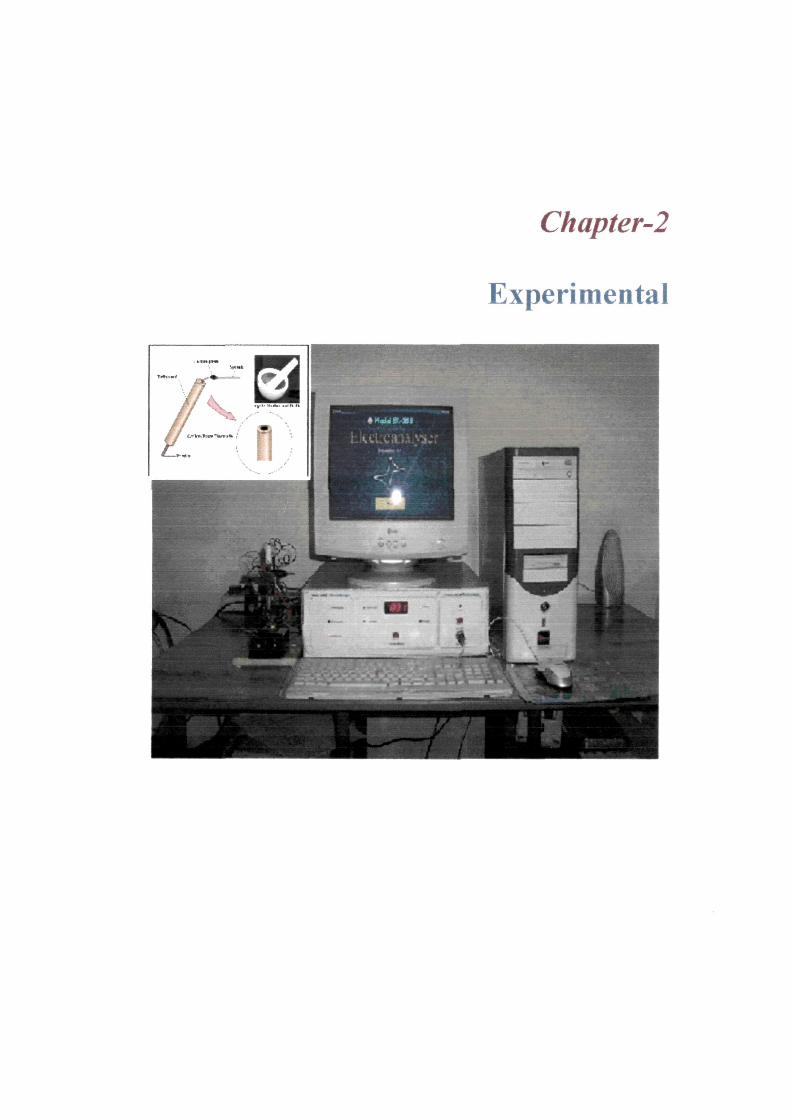
Chapter-2
Experimental
= = = ^ = ^ = ^ = ^ = ^ = ^ = = = = ^ ^ = = ^ = = ^ = ^ ^ Cfiapter-2 ^ = ^ = =
2.1. Introduction
This chapter describes the instrumentation, devices and the electrode systems with
special emphasis on carbon paste electrodes, preparation and standardization of carbon
paste electrodes, experimental techniques and procedures used in the present work. The
basic equipment needed for electrochemistry is a potentiostat, a recording device and an
electrochemical cell. Everything inside the cell is chemistry and everything outside of it
is electronics.
2.2. Potentiostat
A potentiostat is one of the most widely used instruments in electrochemical
studies and makes possible the performance of techniques such as cyclic voltammetry.
A potentiostat system sets the control parameters of the experiment. Its purpose is
to impose on an electrode (the working electrode) a cyclic linear potential sweep and to
output the resulting current-potential curve. This sweep is described in general by its
initial (Ei), switching (Es), final (Ef) potentials, and sweep (or scan) rate (v, in V/s). The
potential as a function of time is:
E = Ei + vt (forward sweep)
E = Es - vt (reverse sweep)
More complicated sweeps are possible, such as in the case where a third
delimiting potential is required and Ei ^Ef. In addition, multiple consecutive cycles are
sometimes used, but in some instances these will not be more informative than a single
cycle. The term linear sweep voltammetry (LSV) is used for a half cycle ('/2CV). In the
present work, two potential values were selected for each cycle, Ei and Ef were made
34
=^===^^^===^=^=^==^=^s=^=^=^ Cfiapter-2 ^ = = ^ = ^
equal and differed from Es. Although the option of a single cycle was used in some
instances, consecutive subsequent cycles were recorded when necessary. The
electrochemical reaction of interest takes place at the working electrode (WE). Electrical
current at the WE due to electron transfer is termed faradic current. The potentiostat
operates with a three-electrode system in an analytical cell. The three-electrode system
function is to maintain the potential of the working electrode at a desired level with
respect to a fixed reference electrode. This goal is achieved by passing the necessary
current between the working electrode and a third electrode, called the counter or
auxiliary electrode (AE). The counter electrode is driven by the potentiostatic circuit to
balance the faradic process at the working electrode with an electron transfer of opposite
direction (e.g. if oxidation takes place at the WE, reduction takes place at the AE). The
process at the AE is not of interest, and in most experiments the small currents observed
mean that the electrolytic products at the AE have no influence on the processes at the
WE. The reference electrode is designed in such a way that its composition is constant
over time and then its potential is fixed. Therefore, any changes in the cell are ascribed to
processes occurring in the working electrode. The faradaic current at the WE is traduced
to a potential output at a selected sensitivity, expressed in amperes per volt and recorded
in a digital or analog form. The cyclic voltammetry (CV) response is plotted as current
versus potential.
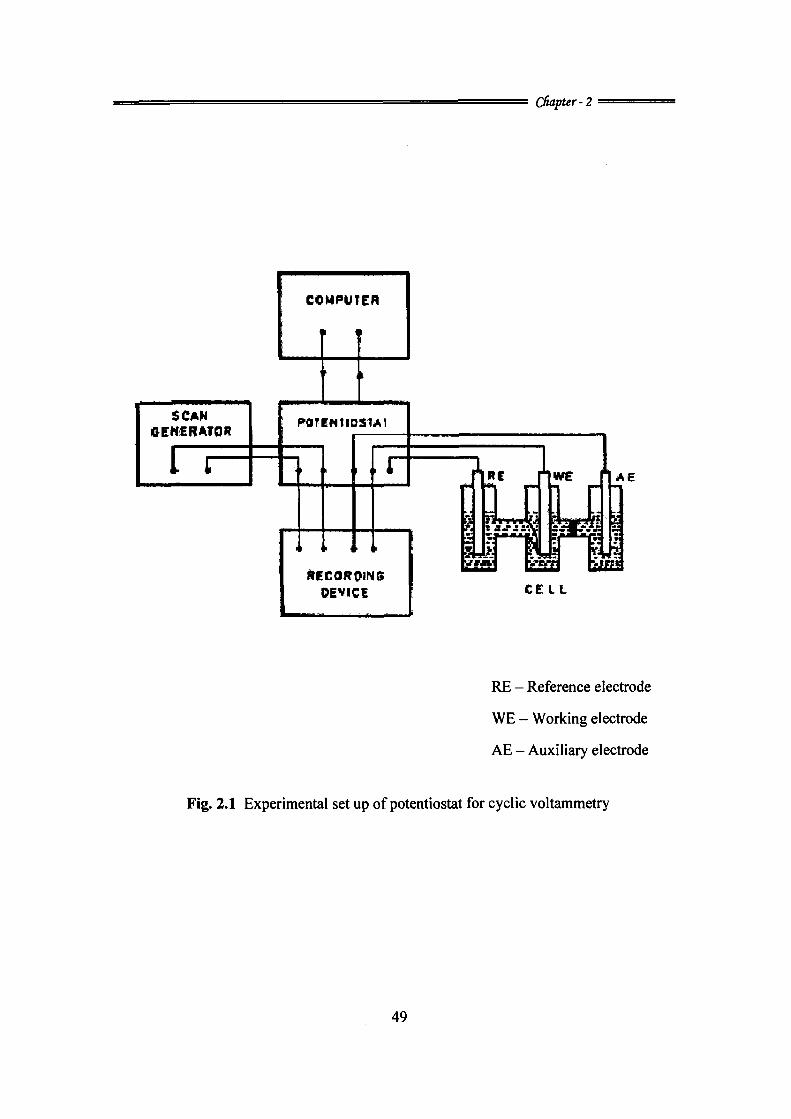
2.2.1. Potentiostat employed in the present work for CV and DPV experiments
The electrochemical experiments were carried out using potentiostat provided
with the Data Acquisition PC interface Card Model EA-201 Electro Analyzer fabricated
by Chemi Link Systems, Trombay, Mumbai, India, compatible with an IBM PC and
35
=^==s^==:^=====^==^=s=======:^ Chapter-2 ==^=^
coupled to a printer (Fig. 2.1). This instrument is capable of performing more than six
electro analytical techniques. The instrument incorporates a high speed, high accuracy
and an electrolysis mode that consists of high-gain operational amplifier with circuits for
controlled potential.
The WE current signal is handled a bit differently. This signal line is also
presented as a voltage signal, but the voltage level is actually proportional to the current
flowing at the WE. The potentiostat has an internal 'current converter' circuit that
performs the necessary current-to-voltage conversion automatically. The current
converter has a number of ranges and the operator is expected to choose the range most
appropriate for the experiment being performed. Each range is associated with a
particular proportionality constant, such as ' 100 mAA ' or ' 1 mAA^.'
2.2.2. Recording device
Computers entered into electro analytical instrumentation in 1967[1] or even
earlier. Computer applications in stationary electrode voltammetry[2,3] and CV[2-6]
were reported. Computers can be used to apply potential programmed to the WE through
the potentiostat. The initial potential, final potential, sweep rate, the nature of the pulse,
current sensitivity etc, may be instructed to the computer in the digital form. Computers
can be used very effectively in data acquisition. The applied potential values and the
resulting current values may be converted into digital information by an A/D converter
and this improves the signal to noise ratio of the experimental cyclic voltammograms.
Computers can repeat each experiment under identical conditions. Computers are used
for the data analysis. It measures peak current or peak potential very accurately[7,8] by
subtraction of background current[4]. Voltammetric curves may be differentiated to
36
= = = = = = = = = = ^ = = ^ = = ^ = ^ = = ^ ^ = ^ = = CfiapteT-2 ^ ^ = ^ ^ ^
obtain peak potentials with greater precision[9].The information thus obtained such as
peak current, peak potential and peak width at various concentrations may then be
correlated with theoretical predictions for establishing the nature of processes and for
evaluating the rate parameters.
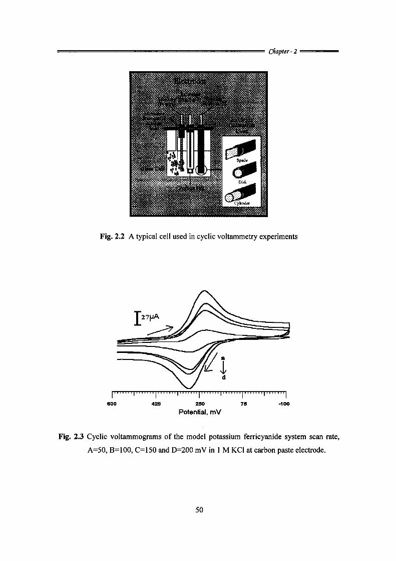
2.3. Apparatus (Electrolysis Cell)
The normal material for cell construction is Pyrex glass for reasons both of
visibility and general chemical inertness.The cell is then maintained oxygen free by
passing nitrogen over the solution through nitrogen inlet. The electrochemical cell
consists of three electrodes which are immersed in this solution and are electrically
connected to the potentiostat. The RE used is SCE, which is often isolated from the
solution by a salt bridge to prevent contamination by leakage from the RE. The AE
(platinum foil) and WEs modified carbon paste electrode, electropolymerised carbon
paste electrode, carbon paste electrode are placed directly into the solution (Fig. 2.2).
Custom glassware designs include convenient fittings for mounting electrodes, gas inlets
and outlets for purging oxygen and temperature jackets. Since the limiting (peak) current
in any type of voltammetry is temperature dependent, the cell is thermo stated for the
required temperature.
2.4. pH Meter
ApH meter is an electronic instrument used to measure the pH (acidity or
alkalinity) of a liquid (though special probes are sometimes used to measure the pH of
semi-solid substances). A typical pH meter consists of a special measuring probe (a glass
electrode) connected to an electronic meter that measures and displays the pH reading.
37
: ^ ^ = ^ = ^ = = = ^ = = ^ ^ = ^ = = = ^ = ^ = ^ = ^ = ^ = Cfiapter-2 '
A pH meter, manufactured by Systronic Digital model 335 was used for
measuring and adjusting the pH of the solutions making use of a combination of glass
and SCE.
2.5. Electrodes
In the present work three electrode system is used i.e. WE / AE / REs. The RE
used is standard calomel electrode (SCE) which is often isolated from the solution by a
salt bridge to prevent contamination by leakage from the RE. The platinum foil as AE
and WEs are carbon paste electrode, or Modified carbon paste electrode.
2.5.1. Electrode pretreatment
Obtaining reproducible results and activating the electrode surface to obtain
reproducible results are the two main objectives of a great variety of pretreatment
procedures reported. Reproducible results can be obtained if the electrode is maintained
in the same state of cleanliness. Mechanical polishing is carried out with metallographic
papers of increasing fineness. The electrode may also be polished using alumina or
diamond powder of 0.05 sizes. This would remove all surface impurities. However, care
must be taken to clean the electrode thoroughly afterwards to ensure that the polishing
materials are completely removed. Otherwise, these polishing materials themselves may
show some specific catalytic or inhibitive effects [10]. The most serious problem
encountered in solid electrode methodology is the difficulty in understanding the true
surface conditions and their possible effects on electrode processes. The surface oxidation
of noble metal electrodes and the presence of adsorbed gas influence the electrode
kinetics in a variety of ways. Thus, it becomes necessary to adopt some standard
38
^=^^^^^^=^^^^^^===^==^^=^^=^=^==^ chapter-! = = = = =
procedure that will produce identical surface conditions and hence enable one to interpret
experimental observations in a useful way. It is possible to obtain reproducible results,
provided the general pretreatment of the electrode is duplicated every time. Hence it is
always essential to clean the electrode surface to rid it of the history effects before
subjecting it to the appropriate pretreatment procedure.
2.5.2. Carbon paste electrodes: Important developments
Carbon paste electrodes (cpe) and related sensors underwent an attractive
development. Its inspiring history, illustrating potentialities of electrochemistry as a
whole reveal numerous connections with the current trends. In the initial stage cpe were
employed mainly in studying the mechanisms of electrode reaction of various organic
compounds [11]. The first modification was done in 1964 in which an organic compound
was dissolved with binder [12] and this, which served to study the electrode behavior of
the substance itself, was considered as a pioneering step in the field of carbon paste
electro active electrodes. In 1965, cpe was prepared by rubbing a modifier into the paste
had represented its case with which a cpe could be modified [13]. The replacement of non
electro active pasting liquids by electrolyte solution [14]in 1974 opened a new branch of
carbon paste electro active electrodes which at present belong to a special field of the so
called solid state electrochemistry [15]. The era of chemically modified electrodes
culminated at the beginning of 80's. Modification of carbon paste by impregnating the
carbon particles with methanol solutions of dimethyl glyoxime [16] represents another
milestone in the history of cpe. The biologically modified cpe as enzymatic biosensors
were introduced in 1988 to monitor some enzymatic ally catalyzed reactions of biological
39
= = ^ = ^ ^ = ^ = ^ ^ = ^ = s = = = ^ = ^ = = = = ^ = = = = ^ = copter-2 ^==^=^=
substances. In 1988, a cpe with glucose oxidize [17] blended into the paste was reported.
The anchoring of enzymes to an electrode material attracted many biochemists and the
field of cpe based enzymatic biosensors grew very fast. The robust carbon composite
electrodes like screen printed electrodes are the newest trend in electrochemistry [18, 19].
2.5.3 Carbon paste as electrode material
2.5.3(a). Unmodified carbon paste
Some carbon pastes may not be totally compact immediately after
homogenization but the required consistency can be achieved by pressing such mixtures
into electrode holders. Too dry or too liquid pastes surface is not renewable in
reproducible way.
Binary Mixtures prepared from carbon powder and organic liquid of non
electrolytic character are known as unmodified ('virgin or bare') carbon pastes [20]. The
electro-active moiety in cpe is still graphite powder with micrometric particles of high
purity and distribution uniformity available as spectroscopic graphite. Non electrolyte
binders Nujol [20] and Silicone oil [21] are non polar pasting liquids which fulfill all the
important criteria like chemically inert, nonvolatile, water immiscible and also known to
form paste mixtures of fine consistency. Silicone oil could be used in non-aqueous
solvents also. Liquid organophosphates are also used [21, 22]. Though they have
attractive property like ion-pairing ability, these are less stable and signal to noise
characteristics require spectral pre treatment. The reasons for the very wide applications
of cpe are their high mechanical stability, low porosity, inertness over a wide potential
range and good conductivity, convenient modification and reproducibility.
40
====^=^============ss=================================s====^ c h a p t e r - 2 ^ ^ = = =
2.5.3(b). Reason to modify carbon paste electrode
The primary reason to modify an electrode is to obtain qualitatively new sensor
with desired, often pre-defined properties. There are four main reasons for modifying cpe
involving typical modifier-substrate interactions which increase the qualities of the
electrodes, i) preferential preconcentration of components of the analyze, ii) exploitation
of catalytic electrochemical responses, iii) immobilization of molecules involved in
electrochemical reactions and iv) alteration of the physical properties of the electrode
surface. Carbon pastes undoubtedly represent one of the most convenient materials for
the preparation of modified electrodes.
2.5.5 (c). Modified carbon pastes
The base of modified cpe is a mixture of powder graphite and non electrolytic
binder [20] the third constituent in the mixture is the modifier itself. Modifying agent is
usually one substance; but, the pastes can also be modified with two or even more
components, which is the case of carbon paste-based biosensors containing enzyme
(its carrier) together with appropriate mediator [23]. Carbon paste represents one of the
most convenient materials for the preparation of modified electrodes [24]. Depending on
the character of modifying agent and its capability of forming enough active sites in
modified paste, the amount of modifier in the paste usually varies between 10-30%
(w/w). In contrast to relatively complicated modifications of solid substrates, cpe can be
modified by simple methods like, dissolving directly in the binder [20,25,26]or admixed
mechanically to the paste during its homogenization [27,28].The various other methods
used include soaking graphite particles with a solution of a modifier and after evaporating
41
= ^ = ^ = = ^ = = ^ = ^ = = ^ ^ ^ = = ^ = = ^ = ^ = = = = ^ = = = Ctuipter-2 ^ ^ ^ = ^ = =
the solvent and thereby impregnating carbon powder [16,19] in situ [29] modification of
cpe also can be done which offer a possibility to employ the same carbon paste for
repetitive modifications. Sensitive Determination of Dopamine and Uric Acid by the Use
of a Glassy Carbon electrode Modified with Poly (3-methylthiophene)/GoId Nanoparticle
Composites [30].Direct Simultaneous Electrochemical Determination of Hydroquinone
and Catechol at a Poly (glutamic acid) Modified Glassy Carbon Electrode [31].
Simultaneous electro analysis of dopamine, ascorbic acid and uric acid by poly (vinyl
alcohol) covalently modified glassy carbon electrode [32].Simultaneous determination of
dopamine and ascorbic acid at the poly (toludine blue) modified electrode[33].Po(v (o-
anisidine) anion composite films as sensing platform for biological molecules[34].
Electro polymerization, characterization and corrosion performance of poly (N-
ethylaniline) on copper [35].Electrochemical characterization of poly (eriochrome
blackT) modified glassy carbon electrode and its application to simultaneous
determination of dopamine, ascorbic acid and uric acid [36].
In this thesis various modifiers which were adopted are Lamotrigine, Eperisone,
Phthalic acid. Salicylic acid, Mannitol, Mulltiwalled nanotube and Surfactants. The
electropolymerisation was achieved using aniline blue, rosaniline, vanillin and tannic
acid.
2.5.4. Some practical aspects on preparation of unmodified carbon paste electrode:
carbon paste components and their choice
Optimal selection of both carbon powder and pasting liquid is the most important
factors influencing the resultant behaviour of CPE [20, 24, and 37].
42
^^=^=====^=^==^^^=^^=^^^===^^ Cfiapter-2 ^ ^ = =
2.5.4(a). Choice of carbon powder
The carbon powders with high uniformity of particle size distribution, high purity
and more or less suppressed adsorption capabilities [20, 37] are preferred in current
measurements based techniques like voltammetry, coulommetry or amperometry. In
contrast to this potentiometer sensors normally do not require the use of graphite's with
so strictly defined properties. The usual particle size of graphite materials reported in the
literature ranges between 5 and 20 ^m [24] and 0.2 ^m for the preparation of carbon
paste micro electrodes [37, 39].The larger particles produce a rough texture and
unfavorable mechanical and electrochemical properties [40]. Too porous materials like
carbon black animal charcoal or similar products are not suitable for the preparation of
carbon pastes.
2.5.4(b). Choice of pasting liquids or binders
The pasting liquids should be non conducting non volatile, immiscible with
aqueous solutions and should exhibit a high chemical and electro chemical
inertness [20,24,37]. Paraffin oil such as nujol and various silicone oils are most
popularly used. Some organic esters like tri cresyl phosphate [29,41,42] dioctyl phthalate
or dinitophenyl octyl [41] either which are found to have ion pairing capabilities are also
being used. Binders give rise to hydrophobic character of the carbon paste surface, which
is in principle the main reason for different behavior of cpe compared to carbon solid
electrodes [20, 24,37].The presence of pasting liquid at the surface decreases the transfer
rate (slower kinetics) causing the higher over potential compared to homogeneous
electrodes [40].The increasing lipophility of the pasting liquid enhances the electrode
over potential (irreversibility). This is due to the marked hydrophobicity of the liquid
which hinders the access of analyte towards the surface. The degree of surface
hydrophobicity of the surface can be decreased by pretreatments.
43
= = = = = = = = = ^ ^ = ^ ^ = = = ^ ^ = ^ = = = ^ = ^ ^ CfiapUr-2 ^ = ^ ^ ^ =
2.5.4(c). Homogenization and preparation of carbon paste electrode for measurement
Preparation of carbon pastes can be done by simply hand mixing of carbon pastes.
This is advantageous because the analyst can by himself choose the individual
components as well as their mutual ratio despite the fact that ready-to-use carbon paste
mixtures are commercially available.
Carbon powder and the pasting liquid can simply be mixed and homogenized
using a pestle and agate. Porcelain dish is avoided due to the possible contaminations of
the paste with porcelain particles originating from the rough rubbing wall. A clean glass
rod is used to mix both the components carefully. The powder so mixed in an agate is
then rubbed by intensive pressing with the pestle for effective homogenization. The paste
is scrapped off the wall with a spatula and ultimately homogenized again and this step is
repeated several times. The paste is kept for 24 hours for self homogenization. The ready
prepared paste is then packed into the well (hole) in the electrode body. Its filling is made
in small portions when each of them being pressed intimately before adding the next one.
2.5.5. Paste composition and surface states on electron transfer rate
Dry graphite gives electron transfer rates which give an almost Nemstian
response and approach those obtained with platinum. The addition of any pasting liquid
decreases these rates. Both electrochemical and chemical oxidative pretreatment of such
paste increase the electron transfer in the direction of the 'dry' graphite limit.
2.5.5(a). Surface renewal
Mechanical renewal of CPE is one of the quickest and very effective method [23].
Thus, easy and quick surface renewal is achieved by simple removal of the used carbon
44
= = ^ = ^ = = ^ = = ^ = ^ ^ = = ^ = ^ = = ^ = ^ = ^ = ^ = = = ^ = = Cfiapter-2 =^=^=^=
paste layer and renewing it with a fresh paste. Practically immediate surface renewal can
be achieved by wiping some paste off using a wet filter paper. If being performed
carefully [43, 21], this procedure provides surface reproducibility nearly comparable to
that attained by rather time-consuming circle-like polishing of the electrode surface upon
a paper pad [44].
2.6. Basic Electrochemical Characteristic of Carbon Pastes Electrode
2.6.1. Potential range and background currents
The potential within which they can be operated is determined mainly by the
quality of graphite and the binder as well as their ratio [20, 24, 37]. Polarizabllity of
carbon pastes was long time believed to depend on the functioning of graphite and the
role of pasting liquid was considered as less significant, influencing only the background
currents level. Studies have shown that polarization limits of a cpe can be controlled
effectively even via the choice of the binder. For e.g. tricresyl phosphate based carbon
paste was found to exhibit extreme polarization limits and could be polarized from -2 to
+2 V in an ammonia buffer [42] and it is a typically broad for any electrode in aqueous
media. A very wide potential window, especially in the negative potential range, was
obtained with a carbon paste containing lipophilic phthalate [42].
2.7. Preparation and Standardization of Carbon Paste Electrode used in the
Present Study
The carbon paste is prepared by intimately mixing spectroscopic grade
carbon powder with a particle size of-10 to 14 \im with the pasting liquid silicone
nujol [12, 24, 45-50]. In the present study the ratio of carbon powder to silicone was
45
^=^=^===^=^==^=^==^====^^^^^ chapter-2 = ^ ^ ^ ^
optimized to Ig: 0.4 ml. An increase in the volume of the pasting liquid greatly affected
the reversibility of the electrode. This was reflected in the greater peak separations AEp in
potassium ferricyanide model system used for the study. The lower volumes of the
binder affected the stability of the electrode. The paste was homogenized by careful
grinding in an agate with the help of a pestle. The well or the cavity in the electrode was
filled with the prepared paste. Fresh electrode surfaces were obtained by polishing on a
weighing paper until they showed a smooth and shiny appearance. After every
measurement, the electrode surface was mechanically regenerated by removing some
paste off (3 mm) and again polishing it on the weighing paper.
2.8. Construction of Carbon Paste Electrode
Cpe holders are typically glass or Teflon rods whose end hole can be easily
refilled with a new portion of carbon paste. The paste is tamped into a well like
depression at one end of the Teflon or glass holder. At this same end, inside the Teflon
tube, a graphite rod is placed and the other end of this graphite rod is connected to a
copper wire which emerges out at the other end of the Teflon tube serves to establish
electrical contact with the external circuit.
2.9. Storage of Carbon Paste Electrode
The cpe could be placed in a beaker containing distilled water and the tip filled
with the paste is completely dipped down to the water level. Such storage prevents the
desiccation of carbon paste. The cpe stored in this manner exhibit a very stable behavior.
46
^ ^ = ^ = = = = = = = = = ^ ^ ^ ^ ^ = ^ = ^ = = = CHapUr-2 ^ ^ ^ ^ ^ ^
2.10. Procedure used to Record Voltammograms
The solutions in the cell were thermo stated to the required temperature. The
electrodes were inserted into the arms of the cell. The supporting electrolyte was taken in
the solvent without adding the analyte in order to record the voltammogram of the blank.
If not mentioned otherwise, before voltammetric measurements the solution was purged
with pure (99.99%) nitrogen for 20 minutes to remove dissolved oxygen and a stream of
nitrogen gas was blanketed over the solution. The potentiostat is programmed for sweep
rates for the measurements. The voltammogram of the blank was recorded. A fixed
volume of the solution of the analyte was taken in the supporting electrolyte and the same
procedure was repeated to record the voltammogram. The electrode surface of the cpe
was renewed mechanically by smoothing some paste off and then polishing on a piece of
transparent paper before conducting each of the experiments. The experiments were
performed in unstirred solutions. A similar procedure is adopted for differential pulse
voltammetric recordings.
2.11. Model System for Basic Characterization of Carbon Paste Electrode in
Voltammetry
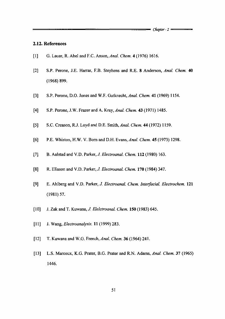
2.11.1(a). Potassium ferricyanide system
The surface of cpe can be studied by its effect on the rate of electron transfer.
This can be judged qualitatively by examining the separation of the peak potentials in a
cyclic voltammogram of a molecule whose electron transfer kinetics are known to be
sensitive to the state of the surface. To evaluate the overall quality of the paste
[Fe(CN)6]^7[[Fe(CN)6]'*~ model system recommended is used [51,52]. The cyclic
47
^ ^ ^ ^ = = = = = = = ^ ^ ^ = ^ ^ = = = = ^ ^ = ^ = ^ = ^ Cfiapter-2 ^ ^ ^ ^ ^ ^
voltammograms obtained at cpe using EA- 201 is depicted in (Fig. 2.3). Well-defined
anodic and cathodic waves were obtained.
2.11.1(b) Calculation of surface area of the electrode
The surface area of cpe was determined using potassium ferricyanide (1 mM)
system in 1 M KCl. The effect of scan rate on cyclic voltammograms of 1 mM solution of
ferricyanide has been studied at 50,100,150 and 200 mVs"'. For a reversible redox
couple, the number of electrons transferred in the electrode reaction can be determined by
the separation between the peak potentials lS.Ep = (Epa-Epc) / n ~ 0.059. The value found
to vary from 0.061 to 0.066, which correspond to one electron transfer. It is found that the
separation of the peak potentials is independent of the scan rate. Also, the ratio of ipa/ipc is
found to be close to one (-0.9855), which is a typical behavior, exhibited by a reversible
electrochemical charge transfer. On substitution of the diffusion-coefficient value
(12.2xl0^cm^s"')[53] in the following equation.
ip = 2.65 X 10 n^^ A Co* Do''' v ''''
where, ip is the peak current in A(ampere), A is the area of the electrode in cm , n the
number of electrons, Co* is the concentration in moles dm" , Do diffusion coefficient in
cm s and v is the scan rate in Vs . The values of ipc ipa obtained at different scan rates
are substituted in the above equation and the average value of surface area is calculated.
The surface area of the electrode was found to be 0.022 cm .
48
CHapter-2
SCAN GENfRATOR
r r
COMPUTER
,k
POTENIIOSIAI
. > . : . i
* * • »
AECORQINS OEVICi
AE
CE LL
RE - Reference electrode
WE - Working electrode
AE - Auxiliary electrode
Fig. 2.1 Experimental set up of potentiostat for cyclic voltammetry
49
C/iapter-2
rbWcdf
B r a M i a l ^
,i.,«i=i
Fig. 2.2 A typical cell used in cyclic voltammetry experiments
111111111111111111111111111111111111111111111111111111111111111 111111111
600 425 250
Potential, mV 75 -100
Fig. 2.3 Cyclic voltammograms of the model potassium ferricyanide system scan rate,
A=50, B=100, C=150 and D=200 mV in 1 M KCI at carbon paste electrode.
50
= = ^ ^ Cfiapter-2 =====
2.12. References
[I] G. Lauer, R. Abel and F.C. Anson, Anal. Chem. 4 (1976) 1616.
[2] S.P. Perone, J.E. Harrar, F.B. Stephens and R.E. 8 Anderson, Anal. Chem. 40
(1968) 899.
[3] S.P. Perone, D.O. Jones and W.F. Gutknecht, Anal. Chem. 41 (1969) 1154.
[4] S.P. Perone, J.W. Frazer and A. Kray, Anal. Chem. 43 (1971) 1485.
[5] S.C. Creason, R.J. Loyd and D.E. Smith, Anal. Chem. 44 (1972) 1159.
[6] P.E. Whiston, H.W. V. Bom and D.H. Evans, Anal. Chem. 45 (1973) 1298.
[7] B. Aalstad and V.D. Parker, J. Electroanal. Chem. 112 (1980) 163.
[8] R. Eliason and V.D. Parker, J. Electroanal. Chem. 170 (1984) 347.
[9] E. Ahlberg and V.D. Parker, J. Electroanal. Chem. Interfacial. Electrochem. 121
(1981)57.
[10] J. Zak and T. Kuwana, J. Elelctroanal. Chem. 150 (1983) 645.
[II] J. Wang, Electroanalysis. 11 (1999) 283.
[12] T. Kuwana and W.G. French, Anal. Chem. 36 (1964) 241.
[13] L.S. Marcoux, K.G. Prater, B.G. Prater and R.N. Adams, Anal. Chem. 37 (1965)
1446.
51
^=====^==^=^^=^==s==^==^===^ CfiapUr-2 =
[14] D. Bauer and M.P. Gaillochet, Electrochim. Acta. 19 (1974) 597.
F. Scholz, B. Meyer, Chem. Soc. Rev. 23 (1994) 341.
K. Ravichandran and R.P. Baldwin, J. Electroanal. Chem. 126 (1981) 293.
W. Matuszewski and M. Trojanovicz, ^na/>'5/. 113 (1988) 735.
C. Wang, K Creasy and B. Shaw, / Electroanal. Chem. 300 (1991) 365.
J. Wang,^«fl(ysr. 119 (1994) 763.
[15
[16;
[17
[18
[19
[20
[21
[22
[23
[24;
[25
[26;
[27
K. Kalcher, J.M. Kauffmann, J. Wang, I. Svancara, K. Vytras, C. Neuhold and
Z. Yang, Electroanalysis. 7 (1995) 5.
I. Svancara and K. Schachl, Chem. Listy. 93 (1999) 490.
I. Svancara, J. Konvalina, K. Schachl, K. Kalcher and K. Vytras, Electroanalysis.
10(1998)435.
L. Gorton, Electroanalysis. 7 (1995) 23.
K. Kalcher, Electroanalysis. 2 (1990) 419.
Z. Q. Zhang, H. Liu, H. Zhang and Y.F. Li, Anal. Chim. Acta. 333 (1996) 119.
S.S. Huang, Y.D. Cheng, B.F. Li and G.D. Liu, Mickrochim. Acta. 130 (1998) 97.
R. Metelka, K. Vytras and A. Bobrowski, J. Solid State Electrochem. 4 (2000)
348.
52
==^^^=^=^=====^=^^==^^^==== copter-2 = = = ^
[28] R. Martinez, M.R. Teresa and I. Gonzalez, Electroanalysis. 10 (1998) 336.
[29] I. Svancara, K. Kalcher, W. Diewald and K. Vytras, Electroanalysis. 8 (1996)
336.
[30] X. Huang, Y. LI, Po Wang and L.Wang, 77/e Japan. Soci. for Anal. Chem. 24
(2008) 1563.
[31] L.Wang, P.Huang, J.Bai, H.Wang, L.Zhang and Y.Zhao, L.Wang, Int. J.
Electrochem. Sci. 2 (2007) 123.
[32] Y. Li and X. Lin, Sens and Actuators B. 115 (2006) 134.
[33] Y.Chen, J.Yuan, X.Wang and C.Tian, Japan Soci.ofAnal. Chem. 20 (2004) 1725.
[34] B. Angaleeswari, R.M. Dura Amirtham, T. Jeevithaa, V. Vaishnavi, T. Eevera,
Sheela Berchmans and V. Yegnaraman, Sens and Actuators B. 129 (2008).
[35] Berrin Duran, Metehan C. Turhan, Gozen Bereket and A. Sezai Sarac,
Electrochimica. Acta. 55 (2009) 104112.
[36] H.Yao, Y.Sun, X.Lin, Y.Tang and L.Huang, Electrochimi. Acta. 52 (2007) 6165.
[37] I. Svancara and K. Vytras, Chem. Listy. 88 (1994) 138.
[38] F.I. Cheng and C.K. Martin, Anal. Chem. 60 (1988) 2163.
[39] J. Wang and J.M. Zadeii, J Electroanal. Chem. 249 (1988) 339.
[40] M. Rice, Z. Galus and R.N. Adams, J Electroanal. Chem. 143 (1983) 89.
53
^ ^ = = = = ^ ^ = ^ ^ = ^ = = = ^ ^ ^ = ^ = = = ^ ^ ^ ^ ^ = = s copter-2 ^ ^ ^ = =
[41] Svancara, M. Pravda, M. Hvizdalova, K. Vytras and K. Kalcher, Electroanalysis.
6 (1994) 663.
[42] I. Svancara and K. Vytras, Anal. Chim. Acta. 273 (1993) 195.
[43] I. Svancara, J. Zima and K.Schachl, Sci. Pap. Univ. Pardubice, Ser. A. 4 (1998)
49.
[44] Z. Navratilova and P. Kula, J. Solid State Electrochem. 4 (2000) 342.
[45] R.N. Adams, Rev. Polarog. 11 (1963) 71.
[46] T. Yao and S. Musha, Anal. Chim. Acta. 110 (1979) 203.
[47] C. Olson and R.N. Adams, Anal. Chim. Acta. 22 (1960) 582.
[48] C. Olson and R.N. Adams, Anal. Chim. Acta. 29 (1963) 358.
[49] P.T. Kissinger and W.R. Heinneman, Laboratory Techniques in Electroanalytical
ChemistryX^ Ed, Marcel Dekker, New York, 1984.
[50] J. Lindquist, Anal. Chem. 52 (1974) 37.
[51 ] Galus and R.N. Adams, J. Phys. Chem. 67 (1963) 866.
[52] P. Doderhgelm, J. Electroanal. Chem. 71 (1976) 109.
[53] H.P. Agarwal, J. Electrochem. S'oc. 110 (1963) 23.
54


![Control of Rotating Electrical Machinesira.lib.polyu.edu.hk/bitstream/10397/81196/1/... · in the next century [20]. Nevertheless, the control, design, and optimization of rotating](https://img.pdfslide.us/doc/110x75/60407c5a603ee3749076257e/control-of-rotating-electrical-in-the-next-century-20-nevertheless-the-control.jpg)