Embed Size (px)
Citation preview

The
inst
ruct
ion
book
leti
san
inte
gral
part
ofth
epr
oduc
t.
Engl
ish
installation, use andmaintenance instructions
Riverside, Goods Road, Belper, Derbyshire. DE56 1 UUTel. 01773 820940 • Fax 01773 820477e-mail: [email protected] • web site: www.robeys.co.uk
FireboxesME 65/60 - ME 70/51 - ME 90/44
ME 90/44 B - ME 90/70 - ME 120/48
Engl
ish
2 H07025460 / DT2000686 - Rev. 00
SUPPLEMENTARY INSTALLATION INSTRUCTIONS FOR THE UK MARKETTO BE READ IN CONJUNCTION WITH THOSE IN THE INSTRUCTION BOOKLET
Please note that it is a legal requirement under England and Wales Building Regulations that theinstallation of the stove is either carried out under Local Authority Building Control approval oris installed by a Competent Person registered with a Government approved Competent PersonsScheme. HETAS Ltd operate such a Scheme and a listing of their Registered Competent Personscan be found on their website at www.hetas.co.uk.
HEALTH AND SAFETY PRECAUTIONS
Special care must be taken when installing the stove such that the requirements of the Health and Safetyat Work Act are met.
HandlingAdequate facilities must be available for loading, unloading and site handling.Ensure compliance with the “Manual Handling Operations 1992 Regulations” as amended. Mechanicalhandling equipment may be required.
Fire CementSome types of fire cement are caustic and should not be allowed to come into contact with the skin. Incase of contact wash immediately with plenty of water.
AsbestosThis stove contains no asbestos. If there is a possibility of disturbing any asbestos in the course ofinstallation then please seek specialist guidance and use appropriate protective equipment.
Metal PartsWhen installing or servicing this stove care should be taken to avoid the possibility of personal injury.Wear suitable gloves
STOVE PERFORMANCE
In the UK the stove has been approved by HETAS Ltd as an intermittent operating appliance for burningwood logs only.
It should be noted that it is an offence to burn wood logs in this stove if it is installed within a SmokeControl Area in the UK.
READ THE INSTRUCTION BOOKLET AND THESE SUPPLEMENTARY INSTRUCTIONSCAREFULLY BEFORE INSTALLATION
These instructions together with those in the instruction booklet cover the basic principles to ensure the satisfactoryinstallation of the stove, although detail may need slight modification to suit particular local site conditions.
In all cases the installation must comply with current Building Regulations, Local AuthorityByelaws and other specifications or regulations as they affect the installation of the stove.It should be noted that the Building Regulations requirements may be met by adopting therelevant recommendations given in British Standards BS 8303, BS 6461 and BS 7566 as analternative means to achieve an equivalent level of performance to that obtained following theguidance given in Approved Document J.
Engl
ish
3H07025460 / DT2000686 - Rev. 00
PREPARATORY WORK AND SAFETY CHECKS
IMPORTANT WARNINGThis stove must not be installed into a chimney that serves any other heating appliance.
There must not be an extractor fan fitted in the same room as the stove as this can cause the stove toemit fumes into the room.
ChimneyIn order for the stove to perform satisfactorily the chimney height must be sufficient to ensure an adequatedraught of approximately 15 Pa so as to clear the products of combustion and prevent smoke problemsinto the room.
NOTE: A chimney height of not less than 4.5 metres measured vertically from the outlet of the stove tothe top of the chimney should be satisfactory. Alternatively the calculation procedure given in BS5854:1980 may be used as the basis for deciding whether a particular chimney design will providesufficient draught.
The outlet from the chimney should be above the roof of the building in accordance with the provisionsof Building Regulations Approved Document J.
If installation is into an existing chimney then it must be sound and have no cracks or other faults whichmight allow fumes into the house. Older properties, especially, may have chimney faults or the crosssection may be too large i.e. more than 230 mm x 230 mm. Remedial action should be taken, if required,seeking expert advice, if necessary. If it is found necessary to line the chimney then a flue liner suitablefor solid fuel must be used in accordance with Building Regulations Approved Document J.
Any existing chimney must be clear of obstruction and have been swept clean immediately beforeinstallation of the stove. If the stove is fitted in place of an open fire then the chimney should be sweptone month after installation to clear any soot falls which may have occurred due to the difference incombustion between the stove and the open fire.
If there is no existing chimney then either a prefabricated block chimney in accordance with BuildingRegulations Approved Document J or a twin walled insulated stainless steel flue to BS EN 1856 can beused. These chimneys must be fitted in accordance with the manufacturer’s instructions and BuildingRegulations.
A single wall metal fluepipe is suitable for connecting the stove to the chimney but is not suitable forusing for the complete chimney. The chimney and connecting fluepipe must have a minimum diameterof 150 mm and its dimension should be not less than the size of the outlet socket of the stove.
Any bend in the chimney or connecting fluepipe should not exceed 45°. 90° bends should not be used.
Combustible material should not be located where the heat dissipating through the walls of fireboxes orflues could ignite it. Therefore when installing the stove in the presence of combustible materials dueaccount must be taken of the guidance on the separation of combustible material given in BuildingRegulations Approved Document J and also in these stove instructions.
If it is found that there is excessive draught in the chimney then either an adjustable flue damper oralternatively a draught stabiliser should be fitted. The adjustable flue damper should not close off theflue entirely but should in its closed position leave a minimum continuous opening free area of at least20 % of the total cross sectional area of the flue or fluepipe.
Adequate provision e.g. easily accessible soot door or access doors, must be provided for sweeping the chimneyand connecting fluepipe, also to permit visual checks on the integrity of the flue when the appliance is serviced.
Engl
ish
4 H07025460 / DT2000686 - Rev. 00
HearthThe hearth should be able to accommodate the weight of the stove and its chimney if the chimney is notindependently supported. The weight of the stove is indicated in the brochure.
The stove should always be installed on a non-combustible hearth of a size and construction that is inaccordance with the provisions of the current Building Regulations Approved Document J.
The clearance distances to combustible material beneath, surrounding or upon the hearth and wallsadjacent to the hearth should comply with the guidance on the separation of combustible material givenin Building Regulations Approved Document J and also in these stove instructions.
If the stove is to be installed on a wooden floor, it must be covered with a non-combustible material atleast 12mm thick, in accordance with Building Regulations Approved Document J, to a distance of 30 cmin front of the stove and 15 cm to each side measuring from the door of the combustion chamber.
Combustion air supplyIn order for the stove to perform efficiently and safely there should be an adequate air supply into the roomin which the stove is installed to provide combustion air. This is particularly necessary if the room isdouble-glazed or a flue draught stabiliser is operating in the same room as the appliance.It may be necessary to increase the air vent size in property with low air permeability [≤ 5.0 m3/(h.m2)]The provision of air supply to the stove must be in accordance with current Building RegulationsApprovedDocument J. An opening window is not appropriate for this purpose.
Connection to chimneyAll the stoves have a rear and/or top flue gas connector that allows connection to either a masonrychimney or a prefabricated factory made insulated metal chimney in accordance with the instructions forthe appliance given in the instruction booklet.
Commissioning and handoverEnsure loose parts are fitted in accordance with the instructions given in the instruction booklet.
On completion of the installation allow a suitable period of time for any fire cement and mortar to dry out,when a small fire may be lit and checked to ensure the smoke and fumes are taken from the stove upthe chimney and emitted safely to atmosphere. Do not run at full output for at least 24 hours.
On completion of the installation and commissioning ensure that the operating instructions for the stoveare left with the customer. Ensure to advise the customer on the correct use of the appliance with the fuelslikely to be used on the stove and warn them to use only the recommended fuels for the stove.
Advise the user what to do should smoke or fumes be emitted from the stove. The customer should bewarned to use a fireguard to BS 6539 in the presence of children, aged and/or infirm persons.Make provision for securing a suitable guard where applicable.
Carbon Monoxide AlarmA carbon monoxide alarm complying with BS EN 50291 must be fitted in the same room as the appliancein accordance with the current Building Regulations Part J. It should be positioned on the ceiling at least300mm from any wall or, if it is located on a wall, as high up as possible (above any doors and windows)but not within 150mm of the ceiling. The alarm should also be between 1m and 3m horizontally from theappliance.
Engl
ish
5H07025460 / DT2000686 - Rev. 00
SUPPLEMENTARY USER OPERATING INSTRUCTIONSTO BE READ IN CONJUNCTION WITH THOSE IN THE INSTRUCTION BOOKLET
WARNING NOTE
Properly installed, operated and maintained this stove will not emit fumes into the dwelling. Occasionalfumes from de-ashing and re-fuelling may occur. However, persistent fume emission is potentiallydangerous and must not be tolerated. If fume emission does persist, then the following immediate actionshould be taken: -
(a) Open doors and windows to ventilate room
(b) Let the fire out or eject and safely dispose of fuel from the appliance
(c) Check for flue or chimney blockage and clean if required
(d) Do not attempt to relight the fire until the cause of the fume emission has been identified and corrected.If necessary seek expert advice.
The most common cause of fume emission is flueway or chimney blockage. For your own safety thesemust be kept clean at all times.
IMPORTANT NOTES
GeneralBefore lighting the stove check with the installer that the installation work and commissioning checksdescribed in the installation instructions have been carried out correctly and that the chimney has beenswept clean, is sound and free from any obstructions. As part of the stoves’ commissioning and handoverthe installer should have shown you how to operate the stove correctly.
Use of fireguardWhen using the stove in situations where children, aged and/or infirm persons are present a fireguardmust be used to prevent accidental contact with the stove. The fireguard should be manufactured inaccordance with BS 8423:2002.
If the fire is left unattended a spark guard to BS3248, specification for spark guards for use with solid fuelappliances should be used.
Chimney cleaningThe chimney should be swept at least once a year for smokeless fuels and a minimum of twice a yearfor wood and other fuels. It is important that the flue connection and chimney are swept prior to lightingup after a prolonged shutdown period.
If the stove is fitted in place of an open fire then the chimney should be swept one month after installationto clear any soot falls which may have occurred due to the difference in combustion between the stoveand the open fire.
In situations where it is not possible to sweep through the stove the installer will have provided alternativemeans, such as a soot door. After sweeping the chimney the stove flue outlet and the flue pipe connectingthe stove to the chimney must be cleaned with a flue brush.
READ THE INSTRUCTION BOOKLET AND THESE INSTRUCTIONS CAREFULLYBEFORE USING THE STOVE
Engl
ish
6 H07025460 / DT2000686 - Rev. 00
Extractor fanThere must not be an extractor fan fitted in the same room as the stove as this can cause the stove toemit smoke and fumes into the room.
Aerosol spraysDo not use an aerosol spray on or near the stove when it is alight.
Use of operating toolsAlways use the operating tools provided when handling parts likely to be hot when the stove is in use.
Chimney FiresIf the chimney is thoroughly and regularly swept, chimney fires should not occur. However, if a chimneyfire does occur turn the air control setting to the minimum, and tightly close the doors of the stove. Thisshould cause the chimney fire to go out in which case the control should be kept at the minimum settinguntil the fire in the stove has gone out. The chimney and flueways should then be cleaned. If the chimneyfire does not go out when the above action is taken then the fire brigade should be called immediately.
After a chimney fire the chimney should be carefully examined for any damage. Expert advice should besought if necessary
Permanent air ventThe stove requires a permanent and adequate air supply in order for it to operate safely and efficiently.In accordance with current Building Regulations the installer may have fitted a permanent air supply ventinto the room in which the stove is installed to provide combustion air. This air vent should not under anycircumstances be shut off or sealed.
HETAS Ltd ApprovalPlease note that HETAS Approval only covers the use of wood on the stove and approval doesnot cover the use of other fuels either alone or mixed with other fuels, nor does it coverinstructions for the use of other fuels.
USER OPERATING INSTRUCTIONS - WOOD
The instructions detailed in the section / in the instruction booklet should be followed.
Door operationDescribe door operation and use of the tool to open and close the doors, if appropriate.
Lighting of firePlace some firelighters or paper and dry kindling wood on the grate and cover with a small amount of fuel.Set air controls to maximum and set light to firelighters or paper. Close the doors and allow fire to burnuntil fuel is well alight then load with more fuel and adjust air controls to the required level of heat output.
Before relighting the fire clean the firebed of excess ash and clinker and empty the ashpan.
RefuellingKeep the firebox well filled (the fuel may be sloped up from the front firebars), but do not allow fuel to spillover the top of the front fire bars. Take care that fuel does not project over the front fire bars or damageto the glass may be caused when the doors are closed
Engl
ish
7H07025460 / DT2000686 - Rev. 00
Flueway cleaningIt is important that the baffle plate and all the stove flueways are kept clean. When burning smokelessfuels they should be cleaned at least monthly. When burning other fuels they should be cleaned at leastonce a week, and more frequently if necessary.
Remove any sooty deposits from the baffle plate.
More soot will be deposited on the baffle plate and in the flueways if the stove is run at low levels for longperiods. If this is the case then more frequent cleaning will be necessary.
Cleaning and maintenanceThe instructions detailed in the section “Maintenance” in the instruction booklet should be followed.
Trouble shootingThe instructions detailed in the relevant section in the instruction booklet should be followed togetherwith the following additional items:
1. Fire Will Not BurnCheck that:a)the air inlet is not obstructed in any way,b)that chimneys and flueways are clear,c) that a suitable fuel is being used,d)that there is an adequate air supply into the room,e)that an extractor fan is not fitted in the same room as the fire.
2. Fire Blazing Out Of ControlCheck that:a)the doors are tightly closed,b)the air control is turned down to the minimum setting,c) the air inlet damper is closed and that it is not prevented from closing completely by a piece of ash,d)a suitable fuel is being used,e) the door seals are in good condition.
DT2011502-00
Registered Office: Robeys Ltd, Goods Road, Belper Derbyshire DE56 1UUTel +44(0)1773 820940 Fax +44(0)1773 820477 Email [email protected] www.robeys.co.uk
Company No. 5741182Director: Mark Robey Company Secretary: Sharon Robey
Engl
ish
8 H07025460 / DT2000686 - Rev. 00
Dear Customer,Thank you for having chosen one of our products, which is the result of years of experience and continuous research aimed at making asuperior product in terms of safety, reliability and performance.This booklet contains information and advice for safe and efficient use of your product.
DT2010001-01
See the guarantee certificate enclosed with the product for the terms, limitations and exclusions.
In line with its policy of constant product improvement and renewal, the manufacturer may make changes without notice.
This document is the property of Gruppo Piazzetta S.p.A.; no part of it may be disclosed to third parties without the written permissionof Gruppo Piazzetta S.p.A.All rights reserved by Gruppo Piazzetta S.p.A..
• This instruction booklet has been prepared by the manufacturerand is an integral part of the product. In the event of sale orrelocation of the product make sure this booklet accompanies it,since the information contained in it is addressed to the purchaserand to anyone involved in the installation, use and maintenanceof the product.
• Read the instructions and the technical information contained inthis booklet carefully before proceeding with installation, use orany repairs.
• The observance of the instructions and technical information inthis manual is essential for the safety of persons and property; italso ensures more efficient operation and an increased lifespan
• Gruppo Piazzetta S.p.A. cannot be held responsible for damage orinjury due to failure to comply with the instructions forinstallation, use and maintenance given in this booklet, or due tounauthorised alterations or to the use of other than original spareparts.
• Appliance installation and use must conform with themanufacturer’s instructions as well as with European and nationallegislation and local regulations.
• The wall against which the product is to be placed must not be ofwood or any other flammable material. For correct installation itis also important to maintain safety distances (refer to the sectionentitled “MINIMUM SAFETY DISTANCES”).
• Prior to completing installation of the surround, light the stoveand when it has heated up check that the grate and that the flueconnection is correct.
• Check that the floor where the product is to be installed isperfectly level.
• Do not fix the heater unit in any way whatsoever, but simply placeit next to the surround.
• When handling the steel parts of the surround or the ceramicparts it is advisable to use clean cotton gloves to avoid leavingfingerprints that are difficult to remove at first time of cleaning
• The firebox must be assembled by two persons.• This appliance has been designed solely for heating. It is not
recommended for cooking foods.• Stop using the product in the event of fault or malfunctioning.• The product you have purchased may differ slightly from the one
illustrated in this booklet since the pictures are only given as anindication and not an exact portrayal.
UNI EN 832 . . . . . . . . . . . . . . . . . . . . . . . .Thermal performance of buildings - Calculation of energy use for heatingUNI EN 13229 . . . . . . . . . . . . . . . . . . . . . .Inset appliances including open fires fired by solid fuels - Requirements and test methodsUNI 10683:2005 . . . . . . . . . . . . . . . . . . . . .Heating appliances fired by wood or other solid biofuels - Installation requirementsUNI EN 13384 . . . . . . . . . . . . . . . . . . . . . .Chimneys - Thermal and fluid dynamic calculation methodsUNI 7129 . . . . . . . . . . . . . . . . . . . . . . . . . .Gas plants for domestic use fed by network distributionUNI 10847 . . . . . . . . . . . . . . . . . . . . . . . . .Chimneys for generators feeded with liquid and solid flues - Maintenance and inspectionEN 1856-1 . . . . . . . . . . . . . . . . . . . . . . . . .Chimneys - Requirements for metal chimneys - Part 1: System chimney productsEN 1856-2 . . . . . . . . . . . . . . . . . . . . . . . . .Chimneys - Requirements for metal chimneys - Part 2: Metal liners and connecting flue pipesUNI EN 1443 . . . . . . . . . . . . . . . . . . . . . . .Chimneys – General requirementsDIN 18 895 . . . . . . . . . . . . . . . . . . . . . . . . .FireboxesDIN 51731 class of measurement HP2 . .Fuels
IMPORTANT INFORMATION DT2010139-00
REFERENCE STANDARDS DT2010140-02
Engl
ish
9H07025460 / DT2000686 - Rev. 00
INDEX DT2010187-01
This booklet code H07025460 / DT2000686 - Rev. 00 - (10/2010) comprises 44 pages.
SECTION TITLE . . . . . . . . . . . . . . . . . . . . . . . . . . . . . . . . . . . . . . . . . . . . . . . . . . . . . . . . . . . . . . . . . . . . . . . . . . . .PAGE
1.0 GENERAL RULES . . . . . . . . . . . . . . . . . . . . . . . . . . . . . . . . . . . . . . . . . . .101.1 SINGLE FLUEWAY OR CHIMNEY . . . . . . . . . . . . . . . . . . . . . . . . . . . . . . .111.2 SOOT INSPECTION . . . . . . . . . . . . . . . . . . . . . . . . . . . . . . . . . . . . . . . . . .111.3 CHIMNEY STACK . . . . . . . . . . . . . . . . . . . . . . . . . . . . . . . . . . . . . . . . . . .121.4 PERMANENT VENTILATION . . . . . . . . . . . . . . . . . . . . . . . . . . . . . . . . . . .131.5 INSTALLATION ENVIRONMENT . . . . . . . . . . . . . . . . . . . . . . . . . . . . . . . .141.6 CAPACITY LOAD OF THE FLOOR . . . . . . . . . . . . . . . . . . . . . . . . . . . . . . .141.7 HEATING CAPACITY . . . . . . . . . . . . . . . . . . . . . . . . . . . . . . . . . . . . . . . . .141.8 METHOD OF HEAT DIFFUSION . . . . . . . . . . . . . . . . . . . . . . . . . . . . . . . . .151.9 SUITABLE HEAT INSULATING MATERIALS . . . . . . . . . . . . . . . . . . . . . . . .161.10 MINIMUM SAFETY DISTANCES . . . . . . . . . . . . . . . . . . . . . . . . . . . . . . . .171.11 CONNECTION TO THE FLUEWAY . . . . . . . . . . . . . . . . . . . . . . . . . . . . . . .181.12 LINING WALL . . . . . . . . . . . . . . . . . . . . . . . . . . . . . . . . . . . . . . . . . . . . . .181.13 HOOK GRILLE . . . . . . . . . . . . . . . . . . . . . . . . . . . . . . . . . . . . . . . . . . . . . .191.14 WOOD MANTEL PROTECTION . . . . . . . . . . . . . . . . . . . . . . . . . . . . . . . . .191.15 ELECTRIC POWER SUPPLY . . . . . . . . . . . . . . . . . . . . . . . . . . . . . . . . . . .191.16 PREVENTION OF DOMESTIC FIRE . . . . . . . . . . . . . . . . . . . . . . . . . . . . . .19
2.0 TECHNICAL DATA AND SPECIFICATIONS . . . . . . . . . . . . . . . . . . . . . . . . .202.1 DESCRIPTION OF THE APPLIANCE . . . . . . . . . . . . . . . . . . . . . . . . . . . . . .202.2 ACCESSORIES AND EQUIPMENT . . . . . . . . . . . . . . . . . . . . . . . . . . . . . . .212.3 FEATURES . . . . . . . . . . . . . . . . . . . . . . . . . . . . . . . . . . . . . . . . . . . . . . . . .212.4 PRODUCT IDENTIFICATION . . . . . . . . . . . . . . . . . . . . . . . . . . . . . . . . . . .222.5 TECHNICAL DATA . . . . . . . . . . . . . . . . . . . . . . . . . . . . . . . . . . . . . . . . . . .222.6 DIMENSIONS ME 65/60 . . . . . . . . . . . . . . . . . . . . . . . . . . . . . . . . . . . . . .232.7 DIMENSIONS ME 70/51 . . . . . . . . . . . . . . . . . . . . . . . . . . . . . . . . . . . . . .232.8 DIMENSIONS ME 90/44 . . . . . . . . . . . . . . . . . . . . . . . . . . . . . . . . . . . . . .232.9 DIMENSIONS ME 90/44 B . . . . . . . . . . . . . . . . . . . . . . . . . . . . . . . . . . . . .232.10 DIMENSIONS ME 90/70 . . . . . . . . . . . . . . . . . . . . . . . . . . . . . . . . . . . . . .242.11 DIMENSIONS ME 120/48 . . . . . . . . . . . . . . . . . . . . . . . . . . . . . . . . . . . . .24
3.0 PREPARATION FOR INSTALLING . . . . . . . . . . . . . . . . . . . . . . . . . . . . . . .25
4.0 USE . . . . . . . . . . . . . . . . . . . . . . . . . . . . . . . . . . . . . . . . . . . . . . . . . . . . . .264.1 FUEL . . . . . . . . . . . . . . . . . . . . . . . . . . . . . . . . . . . . . . . . . . . . . . . . . . . . .264.2 SMOKE DAMPER REGULATION . . . . . . . . . . . . . . . . . . . . . . . . . . . . . . . .274.3 COMBUSTION AIR REGULATION . . . . . . . . . . . . . . . . . . . . . . . . . . . . . . .284.4 LIGHTING FOR THE FIRST TIME . . . . . . . . . . . . . . . . . . . . . . . . . . . . . . . .284.5 LIGHTING . . . . . . . . . . . . . . . . . . . . . . . . . . . . . . . . . . . . . . . . . . . . . . . . .294.6 OPENING THE DOOR . . . . . . . . . . . . . . . . . . . . . . . . . . . . . . . . . . . . . . . .294.7 NIGHT TIME OPERATION AT MINIMUM . . . . . . . . . . . . . . . . . . . . . . . . . .304.8 OPERATION UNDER ADVERSE WEATHER CONDITIONS . . . . . . . . . . . . .304.9 OVERHEATING AND EXTINGUISHING . . . . . . . . . . . . . . . . . . . . . . . . . . . .30
5.0 MAINTENANCE . . . . . . . . . . . . . . . . . . . . . . . . . . . . . . . . . . . . . . . . . . . . .315.1 PERIODIC CECKS . . . . . . . . . . . . . . . . . . . . . . . . . . . . . . . . . . . . . . . . . . .315.2 CLEANING THE CERAMIC CLADDING . . . . . . . . . . . . . . . . . . . . . . . . . . . .315.3 CLEANING THE STEEL PARTS . . . . . . . . . . . . . . . . . . . . . . . . . . . . . . . . .315.4 CLEANING THE PAINTED METAL PARTS . . . . . . . . . . . . . . . . . . . . . . . . .315.5 CLEANING THE GLASS (DAILY) . . . . . . . . . . . . . . . . . . . . . . . . . . . . . . . .325.6 CLEANING THE GRATE AND THE ASH TRAY . . . . . . . . . . . . . . . . . . . . . .325.7 DISPOSAL OF ASHES . . . . . . . . . . . . . . . . . . . . . . . . . . . . . . . . . . . . . . . .325.8 CLEANING ALUKER® . . . . . . . . . . . . . . . . . . . . . . . . . . . . . . . . . . . . . . . .325.9 REMOVING THE SMOKE BAFFLE PLATES . . . . . . . . . . . . . . . . . . . . . . . .335.10 CLEANING THE FAN . . . . . . . . . . . . . . . . . . . . . . . . . . . . . . . . . . . . . . . . .335.11 SHUTTING DOWN . . . . . . . . . . . . . . . . . . . . . . . . . . . . . . . . . . . . . . . . . . .335.12 CLOSING DOOR SYSTEM . . . . . . . . . . . . . . . . . . . . . . . . . . . . . . . . . . . . .33
6.0 TROUBLESHOOTING . . . . . . . . . . . . . . . . . . . . . . . . . . . . . . . . . . . . . . . .34
DECLARATION OF CONFORMITY MODEL ME 65/60 . . . . . . . . . . . . . . . .36DECLARATION OF CONFORMITY MODEL ME 70/51 . . . . . . . . . . . . . . . .37DECLARATION OF CONFORMITY MODEL ME 90/44 . . . . . . . . . . . . . . . .38DECLARATION OF CONFORMITY MODEL ME 90/70 . . . . . . . . . . . . . . . .39DECLARATION OF CONFORMITY MODEL ME 120/48 . . . . . . . . . . . . . . .40

Engl
ish
10 H07025460 / DT2000686 - Rev. 00
1.0 GENERAL RULES DT2011180-00
Before proceeding with installation, choose the most suitable position for your firebox according to the indications given in the paragraph“MINIMUM SAFETY DISTANCES” and to all the indications below.
DT2033293-00
INSPECTIONSOOT DOOR
CHIMNEY POT
FLUEWAY
CONNECTION TO FLUE
MINIMUM SAFETYDISTANCES
CHECK FLOOR FOR LOADBEARING CAPACITY
HOOD GRILL
LINING WALL
PROTECTION FOR ORNAMENTAL LEDGE
FIXED AIR OUTLET
MINIMUM SAFETY DISTANCES
FRESH AIR INTAKE
POWER SUPPLY
POWER SWITCH
MULTIFUOCO VENTILATIONSYSTEM
Fig. 1
Engl
ish
11H07025460 / DT2000686 - Rev. 00
DT2012124-001.1 SINGLE FLUEWAY OR CHIMNEY
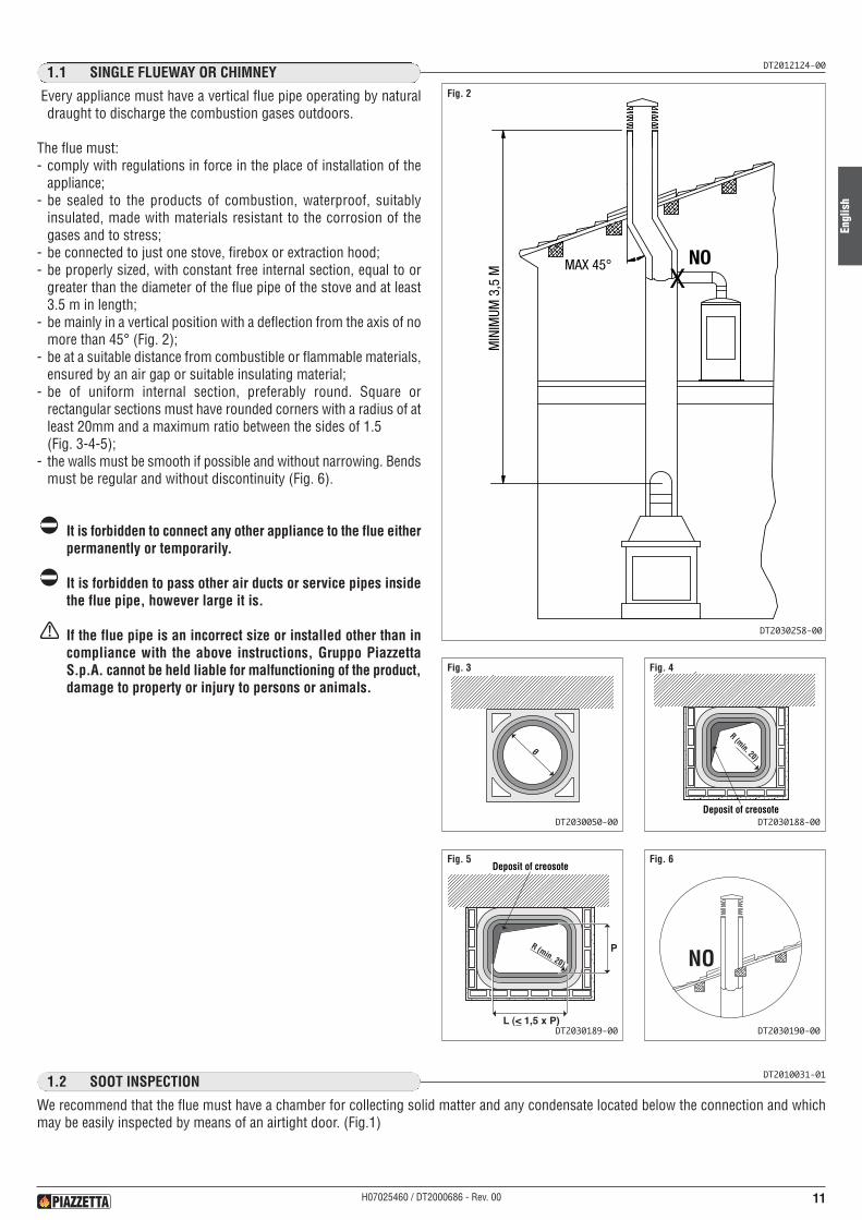
Every appliance must have a vertical flue pipe operating by naturaldraught to discharge the combustion gases outdoors.
The flue must:- comply with regulations in force in the place of installation of the
appliance;- be sealed to the products of combustion, waterproof, suitably
insulated, made with materials resistant to the corrosion of thegases and to stress;
- be connected to just one stove, firebox or extraction hood;- be properly sized, with constant free internal section, equal to or
greater than the diameter of the flue pipe of the stove and at least3.5 m in length;
- be mainly in a vertical position with a deflection from the axis of nomore than 45° (Fig. 2);
- be at a suitable distance from combustible or flammable materials,ensured by an air gap or suitable insulating material;
- be of uniform internal section, preferably round. Square orrectangular sections must have rounded corners with a radius of atleast 20mm and a maximum ratio between the sides of 1.5(Fig. 3-4-5);
- the walls must be smooth if possible and without narrowing. Bendsmust be regular and without discontinuity (Fig. 6).
It is forbidden to connect any other appliance to the flue eitherpermanently or temporarily.
It is forbidden to pass other air ducts or service pipes insidethe flue pipe, however large it is.
If the flue pipe is an incorrect size or installed other than incompliance with the above instructions, Gruppo PiazzettaS.p.A. cannot be held liable for malfunctioning of the product,damage to property or injury to persons or animals.
DT2010031-011.2 SOOT INSPECTION
We recommend that the flue must have a chamber for collecting solid matter and any condensate located below the connection and whichmay be easily inspected by means of an airtight door. (Fig.1)
DT2030258-00
DT2030050-00
Fig. 2
Fig. 3
MAX 45° NOX
MIN
IMUM
3,5
M
Ø
DT2030188-00
Fig. 4
R (min. 20)
Deposit of creosote
DT2030189-00
Fig. 5
PR (min. 20)
L (<_ 1,5 x P)
Deposit of creosote
DT2030190-00
Fig. 6
NO

Engl
ish
12 H07025460 / DT2000686 - Rev. 00
The flue must be fitted at the top with a flue terminal designed to aiddispersion of the products of combustion in the atmosphere.
The flue terminal must comply with the following requirements:- it must have an internal section and shape the same as the flue;- it must have a useful outlet section of not less than twice that of the
flue;- the part of the flue that emerges from the roof or remains in contact
with the outside (e.g. in the case of an open loft), must be coveredwith brick or tile elements and well insulated. It must be built in sucha way as to prevent the penetration of rain, snow and foreign matterinto the flue and to ensure that in the event of winds from all directionsand angle, discharge of the combustion products is assured (flueterminal with down-draught cowl);
- any buildings or other obstacles that are higher than the flue terminalmust not be too close to the actual terminal Fig. 9;
- the flue terminal must be positioned in such a way as to ensureadequate dispersion and dilution of the angle of the roof and positionsee Fig. 10.
Clearances to easily ignited roof coverings (e.g. thatch) need to beincreased in accordance with the building regulations part J.
6-8 m
A
B*
*B free area istwice that of A
A
BB
F
E
CA
G D
B
The illustration and table identify theminimum requirements as dictated byBuilding Regulations
CHIMNEY TERMINATION
Any adjacentbuilding structurewhether connectedor not
N.B. All dimensions relateto the bottom edge of theterminal opening
Fig. 7 Fig. 8
Fig. 9
Fig. 10
DT2030051-00
DT2030052-00
DT2011502-00
DT2030191-00
1.3 CHIMNEY STACKDT2012091-00
Dimension Minimum distance measured from the top of the chimney construction, excluding any pot or terminal
A 2, 3 metres horizontally clear of the roof surface, eg. if the roof pitch is 45°, then the chimney should project 2, 3 metresabove it.
B 1 metre, provided A is satisfied, or 600 mm above the ridge if G is less than 600 mm.
C 1 metre above the top of any flat roof, and the top of any openable root light, dormer window or ventilator, etc.,if it is located within 2, 3 metres.
D/E If D is less than 2, 3 metres, E shall be not less than 600 mm.
F 600 mm above the ridge.
G Edge of chimney to roof ridge.

Engl
ish
13H07025460 / DT2000686 - Rev. 00
To ensure trouble-free operation the stove/firebox must have thenecessary air available for combustion and this is provided throughthe permanent air vent.
The permanent air vent must:- have a total free cross section at least equal to the size given in the
paragraph “TECHNICAL DATA”;- be protected by a grille or suitable guard provided it does not
reduce the minimum recommended section;- be in a position whereby it cannot be obstructed.
The airflow necessary for the fire may be obtained in different ways:- through a permanent air vent direct into the room of installation;- with ducting through pipes direct to the room of installation,
increasing the recommended minimum free cross section by atleast 15%;
- from an adjacent room to the place of installation provided this airflows freely through permanent apertures communicating with theoutside.
If the appliance is being fitted within an existing fireboxrecess, specialist advice should be sought before fitting anypermanent ventilation within this area.
The adjacent room from which air is taken must not have alow pressure compared to the exterior due to a counterdraught caused by the presence in that room of anotherappliance in use or of a suction device.The permanent apertures in the adjacent room must complywith the requirements given above.
Combustion air must not be taken from adjacent rooms usedas a garage or a combustible materials store or for activitiesposing a fire hazard.
The air supply must comply with the current copy of theBuilding Regulations Approved Document J.
1.4 PERMANENT VENTILATIONDT2012090-00
Fig. 12
DT2030260-01
Permanentair vent
Canopygrille
Fig. 11
DT2030259-01
Fig. 13
DT2030261-01
Engl
ish
14 H07025460 / DT2000686 - Rev. 00
DT2010033-011.5 INSTALLATION ENVIRONMENT
The appliance should be installed in a location which allows safe and convenient use as well as easy maintenance. If the product beinginstalled requires an electrical socket, the room must also be provided with an earthed power supply in accordance with current regulations.
The room where the appliance is to be installed must comply with the following requirements:
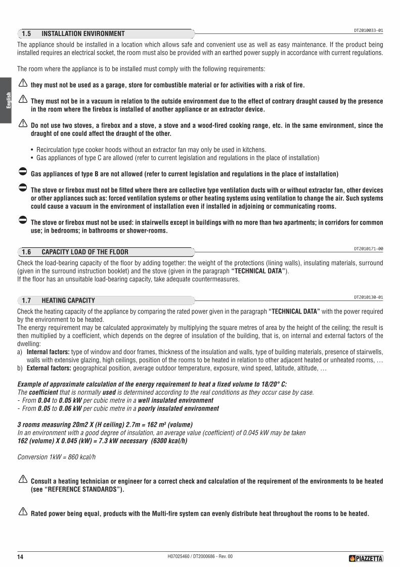
they must not be used as a garage, store for combustible material or for activities with a risk of fire.
They must not be in a vacuum in relation to the outside environment due to the effect of contrary draught caused by the presencein the room where the firebox is installed of another appliance or an extractor device.
Do not use two stoves, a firebox and a stove, a stove and a wood-fired cooking range, etc. in the same environment, since thedraught of one could affect the draught of the other.
• Recirculation type cooker hoods without an extractor fan may only be used in kitchens.• Gas appliances of type C are allowed (refer to current legislation and regulations in the place of installation)
Gas appliances of type B are not allowed (refer to current legislation and regulations in the place of installation)
The stove or firebox must not be fitted where there are collective type ventilation ducts with or without extractor fan, other devicesor other appliances such as: forced ventilation systems or other heating systems using ventilation to change the air. Such systemscould cause a vacuum in the environment of installation even if installed in adjoining or communicating rooms.
The stove or firebox must not be used: in stairwells except in buildings with no more than two apartments; in corridors for commonuse; in bedrooms; in bathrooms or shower-rooms.
DT2010171-001.6 CAPACITY LOAD OF THE FLOOR
Check the load-bearing capacity of the floor by adding together: the weight of the protections (lining walls), insulating materials, surround(given in the surround instruction booklet) and the stove (given in the paragraph “TECHNICAL DATA”).If the floor has an unsuitable load-bearing capacity, take adequate countermeasures.
DT2010130-011.7 HEATING CAPACITY
Check the heating capacity of the appliance by comparing the rated power given in the paragraph “TECHNICAL DATA” with the power requiredby the environment to be heated.The energy requirement may be calculated approximately by multiplying the square metres of area by the height of the ceiling; the result isthen multiplied by a coefficient, which depends on the degree of insulation of the building, that is, on internal and external factors of thedwelling:a) Internal factors: type of window and door frames, thickness of the insulation and walls, type of building materials, presence of stairwells,
walls with extensive glazing, high ceilings, position of the rooms to be heated in relation to other adjacent heated or unheated rooms, …b) External factors: geographical position, average outdoor temperature, exposure, wind speed, latitude, altitude, …
Example of approximate calculation of the energy requirement to heat a fixed volume to 18/20° C:The coefficient that is normally used is determined according to the real conditions as they occur case by case.- From 0.04 to 0.05 kW per cubic metre in a well insulated environment- From 0.05 to 0.06 kW per cubic metre in a poorly insulated environment
3 rooms measuring 20m2 X (H ceiling) 2.7m = 162 m3 (volume)In an environment with a good degree of insulation, an average value (coefficient) of 0.045 kW may be taken162 (volume) X 0.045 (kW) = 7.3 kW necessary (6300 kcal/h)
Conversion 1kW = 860 kcal/h
Consult a heating technician or engineer for a correct check and calculation of the requirement of the environments to be heated(see “REFERENCE STANDARDS”).
Rated power being equal, products with the Multi-fire system can evenly distribute heat throughout the rooms to be heated.
Engl
ish
15H07025460 / DT2000686 - Rev. 00
DT2011183-001.8 METHOD OF HEAT DIFFUSION
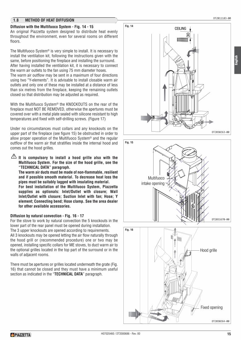
Diffusion with the Multifuoco System - Fig. 14 - 15An original Piazzetta system designed to distribute heat evenlythroughout the environment, even for several rooms on differentfloors.
The Multifuoco System® is very simple to install. It is necessary toinstall the ventilation kit, following the instructions given with thesame, before positioning the fireplace and installing the surround.After having installed the ventilation kit, it is necessary to connectthe warm air outlets to the fan using 75 mm diameter hoses.The warm air outflow may be sent in a maximum of four directionsusing two “Y-elements”. It is advisable to install closable warm airoutlets and only one of these may be installed at a distance of lessthan six metres from the fireplace, keeping the remaining outletsclosed so that distribution may be adjusted as required.
With the Multifuoco System® the KNOCKOUTS on the rear of thefireplace must NOT BE REMOVED, otherwise the apertures must becovered over with a metal plate sealed with silicone resistant to hightemperatures and fixed with self-drilling screws. (Figure 17)
Under no circumstances must collars and any knockouts on theupper part of the fireplace (see figure 15) be obstructed in order toallow proper operation of the Multifuoco System® and the regularoutflow of the warm air that stratifies inside the internal hood andcomes out the hood grilles.
It is compulsory to install a hood grille also with theMultifuoco System. For the size of the hood grille, see the“TECHNICAL DATA” paragraph.The warm air ducts must be made of non-flammable, resilientand if possible smooth material. To decrease heat loss thepipes must be suitably lagged with insulating material.For best installation of the Multifuoco System, Piazzettasupplies as optionals: Inlet/Outlet with closure; WallInlet/Outlet with closure; Suction Inlet with fan; Hose; Yelement; Connecting bend; Hose clamp. See the area dealerfor other available accessories.
Diffusion by natural convection - Fig. 16 - 17For the stove to work by natural convection the 5 knockouts in thelower part of the rear panel must be opened during installation.The 3 upper knockouts are opened according to requirements.All 3 knockouts may be opened letting the air flow naturally throughthe hood grill or (recommended procedure) one or two may beopened, installing specific collars for ME stoves, to duct warm air tothe optional grilles located in the top part of the surround or in thewalls of adjacent rooms.
There must be apertures or grilles located underneath the grate (Fig.16) that cannot be closed and they must have a minimum usefulsection as indicated in the “TECHNICAL DATA” paragraph.
CEILINGFig. 14
DT2030263-00
Multifuocointake opening
Fig. 15
DT2031670-00
Griglia di cappaHood grille
Fixed opening
Fig. 16
DT2030264-00
Engl
ish
16 H07025460 / DT2000686 - Rev. 00
Fig. 17
Semitrancisuperiori
Semitranciinferiori
UPPERKNOCKOUTS
LOWERKNOCKOUTS
DT2032730-00
Fig. 18
DT2030172-00
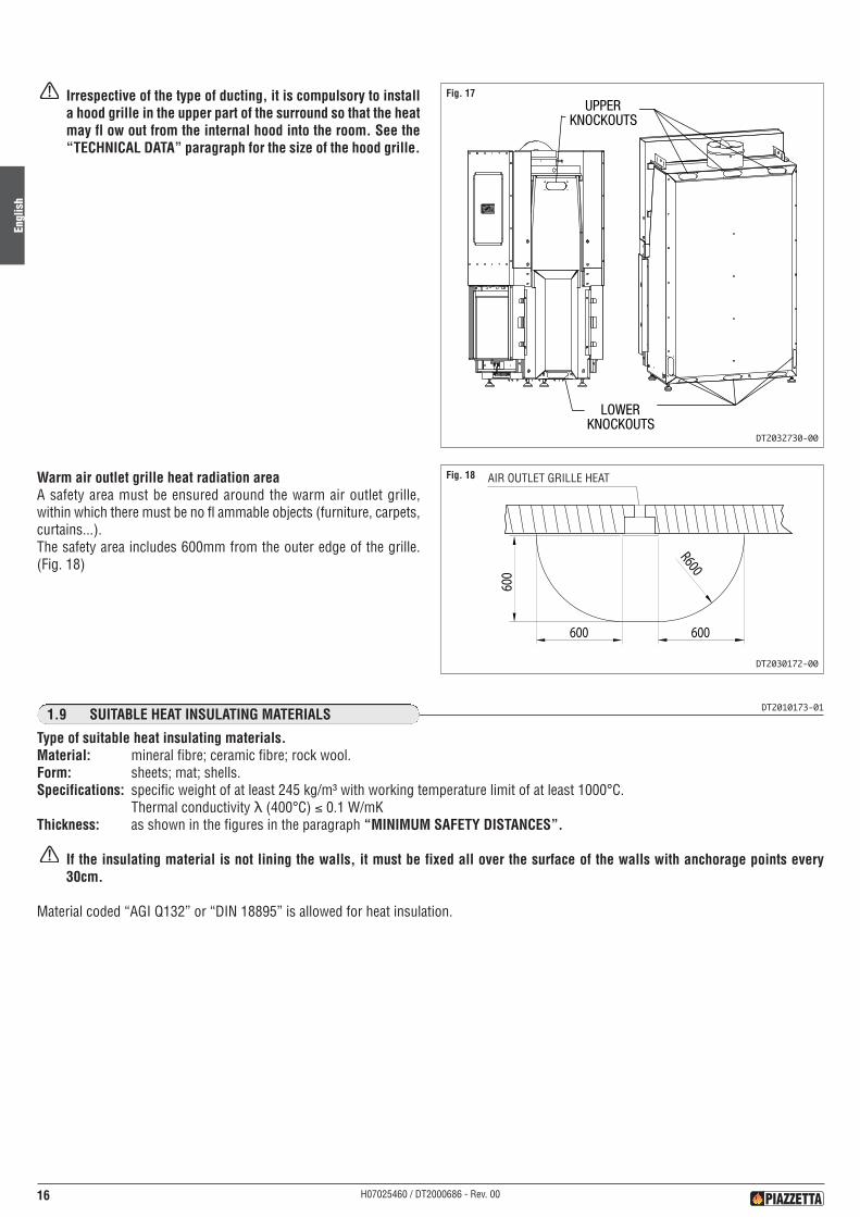
Irrespective of the type of ducting, it is compulsory to installa hood grille in the upper part of the surround so that the heatmay fl ow out from the internal hood into the room. See the“TECHNICAL DATA” paragraph for the size of the hood grille.
Warm air outlet grille heat radiation areaA safety area must be ensured around the warm air outlet grille,within which there must be no fl ammable objects (furniture, carpets,curtains...).The safety area includes 600mm from the outer edge of the grille.(Fig. 18)
DT2010173-011.9 SUITABLE HEAT INSULATING MATERIALS
Type of suitable heat insulating materials.Material: mineral fibre; ceramic fibre; rock wool.Form: sheets; mat; shells.Specifications: specific weight of at least 245 kg/m³ with working temperature limit of at least 1000°C.
Thermal conductivity λ (400°C) ≤ 0.1 W/mKThickness: as shown in the figures in the paragraph “MINIMUM SAFETY DISTANCES”.
If the insulating material is not lining the walls, it must be fixed all over the surface of the walls with anchorage points every30cm.
Material coded “AGI Q132” or “DIN 18895” is allowed for heat insulation.
AIR OUTLET GRILLE HEAT
Engl
ish
17H07025460 / DT2000686 - Rev. 00
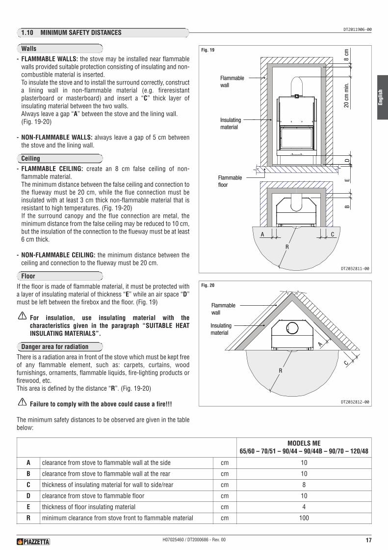
DT2011906-001.10 MINIMUM SAFETY DISTANCES
Ceiling
Floor
Danger area for radiation
- FLAMMABLE WALLS: the stove may be installed near flammablewalls provided suitable protection consisting of insulating and non-combustible material is inserted.To insulate the stove and to install the surround correctly, constructa lining wall in non-flammable material (e.g. fireresistantplasterboard or masterboard) and insert a “C” thick layer ofinsulating material between the two walls.Always leave a gap “A” between the stove and the lining wall.(Fig. 19-20)
- NON-FLAMMABLE WALLS: always leave a gap of 5 cm betweenthe stove and the lining wall.
- FLAMMABLE CEILING: create an 8 cm false ceiling of non-flammable material.The minimum distance between the false ceiling and connection tothe flueway must be 20 cm, while the flue connection must beinsulated with at least 3 cm thick non-flammable material that isresistant to high temperatures. (Fig. 19-20)If the surround canopy and the flue connection are metal, theminimum distance from the false ceiling may be reduced to 10 cm,but the insulation of the connection to the flueway must be at least6 cm thick.
- NON-FLAMMABLE CEILING: the minimum distance between theceiling and connection to the flueway must be 20 cm.
If the floor is made of flammable material, it must be protected witha layer of insulating material of thickness “E” while an air space “D”must be left between the firebox and the floor. (Fig. 19)
For insulation, use insulating material with thecharacteristics given in the paragraph “SUITABLE HEATINSULATING MATERIALS”.
There is a radiation area in front of the stove which must be kept freeof any flammable element, such as: carpets, curtains, woodfurnishings, ornaments, flammable liquids, fire-lighting products orfirewood, etc.This area is defined by the distance “R”. (Fig. 19-20)
Failure to comply with the above could cause a fire!!!
The minimum safety distances to be observed are given in the tablebelow:
A C
BE
D
Flammablewall
Insulatingmaterial
Flammablefloor
R
8cm
20cm
min
.
Fig. 19
DT2032811-00
A
CR
Flammablewall
Insulatingmaterial
Fig. 20
DT2032812-00
MODELS ME65/60 – 70/51 – 90/44 – 90/44B – 90/70 – 120/48
A clearance from stove to flammable wall at the side cm 10
B clearance from stove to flammable wall at the rear cm 10
C thickness of insulating material for wall to side/rear cm 8
D clearance from stove to flammable floor cm 10
E thickness of floor insulating material cm 4
R minimum clearance from stove front to flammable material cm 100
Walls
Engl
ish
18 H07025460 / DT2000686 - Rev. 00
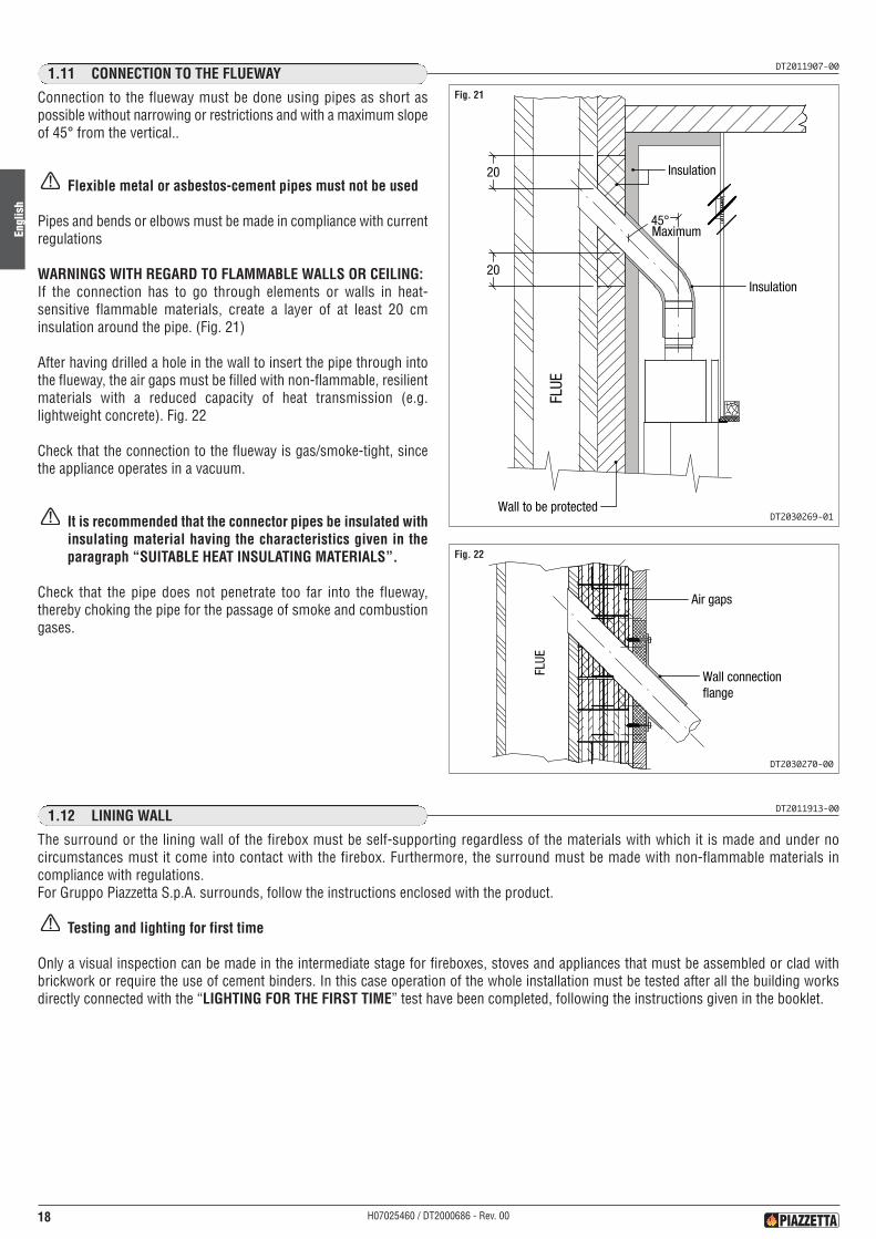
DT2011907-001.11 CONNECTION TO THE FLUEWAY
Connection to the flueway must be done using pipes as short aspossible without narrowing or restrictions and with a maximum slopeof 45° from the vertical..
Flexible metal or asbestos-cement pipes must not be used
Pipes and bends or elbows must be made in compliance with currentregulations
WARNINGS WITH REGARD TO FLAMMABLE WALLS OR CEILING:If the connection has to go through elements or walls in heat-sensitive flammable materials, create a layer of at least 20 cminsulation around the pipe. (Fig. 21)
After having drilled a hole in the wall to insert the pipe through intothe flueway, the air gaps must be filled with non-flammable, resilientmaterials with a reduced capacity of heat transmission (e.g.lightweight concrete). Fig. 22
Check that the connection to the flueway is gas/smoke-tight, sincethe appliance operates in a vacuum.
It is recommended that the connector pipes be insulated withinsulating material having the characteristics given in theparagraph “SUITABLE HEAT INSULATING MATERIALS”.
Check that the pipe does not penetrate too far into the flueway,thereby choking the pipe for the passage of smoke and combustiongases.
45°
FLUE
20
20
Insulation
Wall to be protected
Insulation
Maximum
Fig. 21
DT2030269-01
FLUE
Air gaps
Wall connectionflange
Fig. 22
DT2030270-00
DT2011913-001.12 LINING WALL
The surround or the lining wall of the firebox must be self-supporting regardless of the materials with which it is made and under nocircumstances must it come into contact with the firebox. Furthermore, the surround must be made with non-flammable materials incompliance with regulations.For Gruppo Piazzetta S.p.A. surrounds, follow the instructions enclosed with the product.
Testing and lighting for first time
Only a visual inspection can be made in the intermediate stage for fireboxes, stoves and appliances that must be assembled or clad withbrickwork or require the use of cement binders. In this case operation of the whole installation must be tested after all the building worksdirectly connected with the “LIGHTING FOR THE FIRST TIME” test have been completed, following the instructions given in the booklet.

Engl
ish
19H07025460 / DT2000686 - Rev. 00
DT2010177-001.13 HOOD GRILLE
The hood grille has the function of allowing air to pass from insidethe hood to the environment or vice versa if the Multifuoco systemis installed.Warm air comes out of the hood grille with the natural convectionsystem and it is therefore necessary to maintain the safety distancesfrom flammable materials such as: flammable ceilings or walls,ledges/beams, furniture, curtains, etc.. The hood grille must beinstalled at least 50cm from the ceiling and with at least 30cm safetydistance to the sides.For the hood grille size, see the “TECHNICAL DATA” paragraph.
A non-closable hood grille must be installed withoutconnecting it to the stove so that the warm air that hasstratified inside the lining wall can flow out.
With a ceiling over 3 metres high, a NON-CLOSABLE hoodgrille must be installed on the hood lining at a height of 30cmfrom the ceiling to allow the stratified air to flow out.
MIN. 30 CM MIN. 30 CM
MIN
.30
CM
FLA
MM
AB
LEM
AT
ER
IALS
FLA
MM
AB
LEM
AT
ER
IALS
CEILING IN FLAMMABLE MATERIAL
Fig. 23
DT2030271-00
DT2010178-001.14 WOOD MANTEL PROTECTION
Wooden finishes, e.g. wood mantels, may be mounted on thesurround.Wood mantels must be:- installed outside the heat radiation area;- self-supporting;- installed with 1cm air gap from the surround or from the heating
part (Fig. 24).
The expansion joint is in ceramic fibre, which has thefunction of insulating the surround from the metal structure ofthe stove. 1
cm
Fire
box
Hoo
dor
surr
ound
1 cm
Surround
Expansion joint
Load-bearing axis
Woodmantel
Fig. 24
DT2030272-00
1.1 NORMATIVE DI RIFERIMENTODT2010027-02
1.16 PREVENTION OF DOMESTIC FIRES
The product must be installed and used in compliance with the manufacturer’s instructions and European and national standards as wellas local regulations.
when a flue pipe passes through a wall or a ceiling, special installation methods must be applied (protection, thermal insulation,distances from heat-sensitive materials, etc.) See the paragraph “CONNECTION TO THE FLUEWAY”
- It is also recommended that all elements made of combustible or inflammable material, such as beams, wooden furniture, curtaining,flammable liquids, etc. be kept outside the heat radiation range of the stove and at a distance of at least 1m from the heating block.
- For other information, see the paragraph “MINIMUM SAFETY DISTANCES” and “CONNECTION TO THE FLUEWAY”.- The flue pipe, chimney stack, chimney and fresh air intake must always be free of obstructions, clean and checked periodically, that is, at
least twice during the seasonal period from the lighting of the stove and during its use. When the stove has not been used for some timeit is advisable to carry out the checks mentioned above. For further information, consult a chimneysweep.
- Only use recommended fuels (See paragraph “FUEL”).- Ensure compliance with building regulations document J.
1.1 NORMATIVE DI RIFERIMENTODT2010179-01
1.15 ELECTRIC POWER SUPPLYMake sure there is a power socket 230V 50Hz in the rear stove wall ready for installing the ventilation kit and a switch on the outside of thecladding to be able to cut off the power supply during maintenance or when the appliance is not being used.The installation must be earthed and fitted with a circuit breaker in accordance with current wiring regulations.The installation of any electrical services during the installation of this appliance must be carried out by a registered competent electricianand in accordance with the requirements of the latest issue of BS 7671.
When connected ensure that the power cable does not come into contact with hot parts.
Engl
ish
20 H07025460 / DT2000686 - Rev. 00
1.1 NORMATIVE DI RIFERIMENTO
2.0 TECHNICAL DATA AND SPECIFICATION DT2011181-02
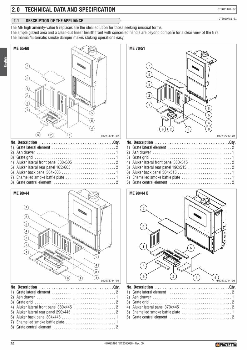
DT2010781-012.1 DESCRIPTION OF THE APPLIANCE
The ME high amenity-value fi replaces are the ideal solution for those seeking unusual forms.The ample glazed area and a clean-cut linear hearth front with concealed handle are beyond compare for a clear view of the fi re.The manual/automatic smoke damper makes stoking operations easy.
No. Description . . . . . . . . . . . . . . . . . . . . . . . . . . . . . . .Qty.1) Grate lateral element . . . . . . . . . . . . . . . . . . . . . . . . . . . . . . . 22) Ash drawer . . . . . . . . . . . . . . . . . . . . . . . . . . . . . . . . . . . . . . 13) Grate grid . . . . . . . . . . . . . . . . . . . . . . . . . . . . . . . . . . . . . . . 14) Aluker lateral front panel 380x605 . . . . . . . . . . . . . . . . . . . . 25) Aluker lateral rear panel 165x605 . . . . . . . . . . . . . . . . . . . . . 26) Aluker back panel 304x605 . . . . . . . . . . . . . . . . . . . . . . . . . . 17) Enamelled smoke baffle plate . . . . . . . . . . . . . . . . . . . . . . . . 18) Grate central element . . . . . . . . . . . . . . . . . . . . . . . . . . . . . . 2
ME 65/60
DT2031744-00
No. Description . . . . . . . . . . . . . . . . . . . . . . . . . . . . . . .Qty.1) Grate lateral element . . . . . . . . . . . . . . . . . . . . . . . . . . . . . . . 22) Ash drawer . . . . . . . . . . . . . . . . . . . . . . . . . . . . . . . . . . . . . . 13) Grate grid . . . . . . . . . . . . . . . . . . . . . . . . . . . . . . . . . . . . . . . 24) Aluker lateral front panel 380x445 . . . . . . . . . . . . . . . . . . . . 25) Aluker lateral rear panel 290x445 . . . . . . . . . . . . . . . . . . . . . 26) Aluker back panel 304x445 . . . . . . . . . . . . . . . . . . . . . . . . . . 17) Enamelled smoke baffle plate . . . . . . . . . . . . . . . . . . . . . . . . 18) Grate central element . . . . . . . . . . . . . . . . . . . . . . . . . . . . . . 2
ME 90/44
DT2031744-00
No. Description . . . . . . . . . . . . . . . . . . . . . . . . . . . . . . .Qty.1) Grate lateral element . . . . . . . . . . . . . . . . . . . . . . . . . . . . . . . 22) Ash drawer . . . . . . . . . . . . . . . . . . . . . . . . . . . . . . . . . . . . . . 13) Grate grid . . . . . . . . . . . . . . . . . . . . . . . . . . . . . . . . . . . . . . . 14) Aluker lateral front panel 380x515 . . . . . . . . . . . . . . . . . . . . 25) Aluker lateral rear panel 190x515 . . . . . . . . . . . . . . . . . . . . . 26) Aluker back panel 304x515 . . . . . . . . . . . . . . . . . . . . . . . . . . 17) Enamelled smoke baffle plate . . . . . . . . . . . . . . . . . . . . . . . . 18) Grate central element . . . . . . . . . . . . . . . . . . . . . . . . . . . . . . 2
4
5
7
6
5
4
18
1
2
3
8
ME 70/51
DT2032742-00
No. Description . . . . . . . . . . . . . . . . . . . . . . . . . . . . . . .Qty.1) Grate lateral element . . . . . . . . . . . . . . . . . . . . . . . . . . . . . . 22) Ash drawer . . . . . . . . . . . . . . . . . . . . . . . . . . . . . . . . . . . . . . 13) Grate grid . . . . . . . . . . . . . . . . . . . . . . . . . . . . . . . . . . . . . . . 24) Aluker lateral panel 370x445 . . . . . . . . . . . . . . . . . . . . . . . . 25) Enamelled smoke baffle plate . . . . . . . . . . . . . . . . . . . . . . . . 16) Grate central element . . . . . . . . . . . . . . . . . . . . . . . . . . . . . . 2
3
5
4126
4
1 6
ME 90/44 B
DT2031744-00
Engl
ish
21H07025460 / DT2000686 - Rev. 00
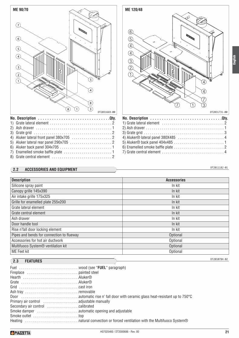
No. Description . . . . . . . . . . . . . . . . . . . . . . . . . . . . . . .Qty.1) Grate lateral element . . . . . . . . . . . . . . . . . . . . . . . . . . . . . . . 22) Ash drawer . . . . . . . . . . . . . . . . . . . . . . . . . . . . . . . . . . . . . . 13) Grate grid . . . . . . . . . . . . . . . . . . . . . . . . . . . . . . . . . . . . . . . 24) Aluker lateral front panel 380x705 . . . . . . . . . . . . . . . . . . . . 25) Aluker lateral rear panel 290x705 . . . . . . . . . . . . . . . . . . . . . 26) Aluker back panel 304x705 . . . . . . . . . . . . . . . . . . . . . . . . . . 17) Enamelled smoke baffle plate . . . . . . . . . . . . . . . . . . . . . . . . 18) Grate central element . . . . . . . . . . . . . . . . . . . . . . . . . . . . . . 2
ME 90/70
DT2031669-00
No. Description . . . . . . . . . . . . . . . . . . . . . . . . . . . . . . .Qty.1) Grate lateral element . . . . . . . . . . . . . . . . . . . . . . . . . . . . . . . 22) Ash drawer . . . . . . . . . . . . . . . . . . . . . . . . . . . . . . . . . . . . . . . 13) Grate grid . . . . . . . . . . . . . . . . . . . . . . . . . . . . . . . . . . . . . . . . 34) Aluker® lateral panel 380X485 . . . . . . . . . . . . . . . . . . . . . . . 45) Aluker® back panel 404x485 . . . . . . . . . . . . . . . . . . . . . . . . . 16) Enamelled smoke baffle plate . . . . . . . . . . . . . . . . . . . . . . . . . 27) Grate central element . . . . . . . . . . . . . . . . . . . . . . . . . . . . . . . 4
ME 120/48
DT2031731-00
DT2011182-012.2 ACCESSORIES AND EQUIPMENT
DT2010784-022.3 FEATURES
Fuel . . . . . . . . . . . . . . . . . . . . . . . . . . . . . .wood (see “FUEL“ paragraph)Fireplace . . . . . . . . . . . . . . . . . . . . . . . . . .painted steelHearth . . . . . . . . . . . . . . . . . . . . . . . . . . . .Aluker®Grate . . . . . . . . . . . . . . . . . . . . . . . . . . . . .Aluker®Grid . . . . . . . . . . . . . . . . . . . . . . . . . . . . . .cast ironAsh tray . . . . . . . . . . . . . . . . . . . . . . . . . . .removableDoor . . . . . . . . . . . . . . . . . . . . . . . . . . . . .automatic rise n’ fall door with ceramic glass heat-resistant up to 750°CPrimary air control . . . . . . . . . . . . . . . . . .adjustable manuallySecondary air control . . . . . . . . . . . . . . . .calibratedSmoke damper . . . . . . . . . . . . . . . . . . . . .automatic opening and adjustableSmoke outlet . . . . . . . . . . . . . . . . . . . . . . .topHeating . . . . . . . . . . . . . . . . . . . . . . . . . . .natural convection or forced ventilation with the Multifuoco System®
Description AccessoriesSilicone spray paint In kitCanopy grille 145x390 In kitAir intake grille 175x325 In kitGrille for enamelled plate 255x200 In kitGrate lateral element In kitGrate central element In kitAsh drawer In kitDoor handle tool In kitRise n’fall door locking element In kitPipes and bends for connection to flueway OptionalAccessories for hot air ductwork OptionalMultifuoco System® ventilation kit OptionalME Feet kit Optional
Engl
ish
22 H07025460 / DT2000686 - Rev. 00
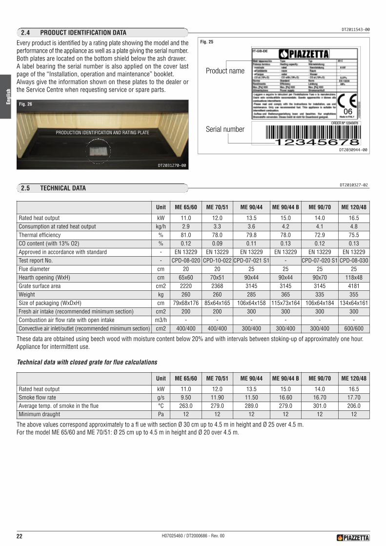
DT2011543-002.4 PRODUCT IDENTIFICATION DATA
Every product is identified by a rating plate showing the model and theperformance of the appliance as well as a plate giving the serial number.Both plates are located on the bottom shield below the ash drawer.A label bearing the serial number is also applied on the cover lastpage of the “Installation, operation and maintenance” booklet.Always give the information shown on these plates to the dealer orthe Service Centre when requesting service or spare parts.
Product name
Serial number
Fig. 25
DT2030944-00
Fig. 26
DT2031270-00
PRODUCTION IDENTIFICATION AND RATING PLATE
Unit ME 65/60 ME 70/51 ME 90/44 ME 90/44 B ME 90/70 ME 120/48
Rated heat output kW 11.0 12.0 13.5 15.0 14.0 16.5Consumption at rated heat output kg/h 2.9 3.3 3.6 4.2 4.1 4.8Thermal efficiency % 81.0 78.0 79.8 78.0 72.9 75.5CO content (with 13% O2) % 0.12 0.09 0.11 0.13 0.12 0.13Approved in accordance with standard - EN 13229 EN 13229 EN 13229 EN 13229 EN 13229 EN 13229Test report No. - CPD-08-020 CPD-10-022 CPD-07-021 S1 - CPD-07-020 S1 CPD-08-030Flue diameter cm 20 20 25 25 25 25Hearth opening (WxH) cm 65x60 70x51 90x44 90x44 90x70 118x48Grate surface area cm2 2220 2368 3145 3145 3145 4181Weight kg 260 260 285 365 335 355Size of packaging (WxDxH) cm 79x68x176 85x64x165 106x64x158 115x73x164 106x64x184 134x64x161Fresh air intake (recommended minimum section) cm2 200 200 300 300 300 300Combustion air flow rate with open intake m3/h - - - - - -Convective air inlet/outlet (recommended minimum section) cm2 400/400 400/400 300/400 300/400 300/400 600/600
Unit ME 65/60 ME 70/51 ME 90/44 ME 90/44 B ME 90/70 ME 120/48
Rated heat output kW 11.0 12.0 13.5 15.0 14.0 16.5Smoke flow rate g/s 9.50 11.90 11.50 16.60 16.70 17.70Average temp. of smoke in the flue °C 263.0 279.0 289.0 279.0 301.0 206.0Minimum draught Pa 12 12 12 12 12 12
DT2010327-022.5 TECHNICAL DATA
These data are obtained using beech wood with moisture content below 20% and with intervals between stoking-up of approximately one hour.Appliance for intermittent use.
Technical data with closed grate for flue calculations
The above values correspond approximately to a fl ue with section Ø 30 cm up to 4.5 m in height and Ø 25 over 4.5 m.For the model ME 65/60 and ME 70/51: Ø 25 cm up to 4.5 m in height and Ø 20 over 4.5 m.
Engl
ish
23H07025460 / DT2000686 - Rev. 00
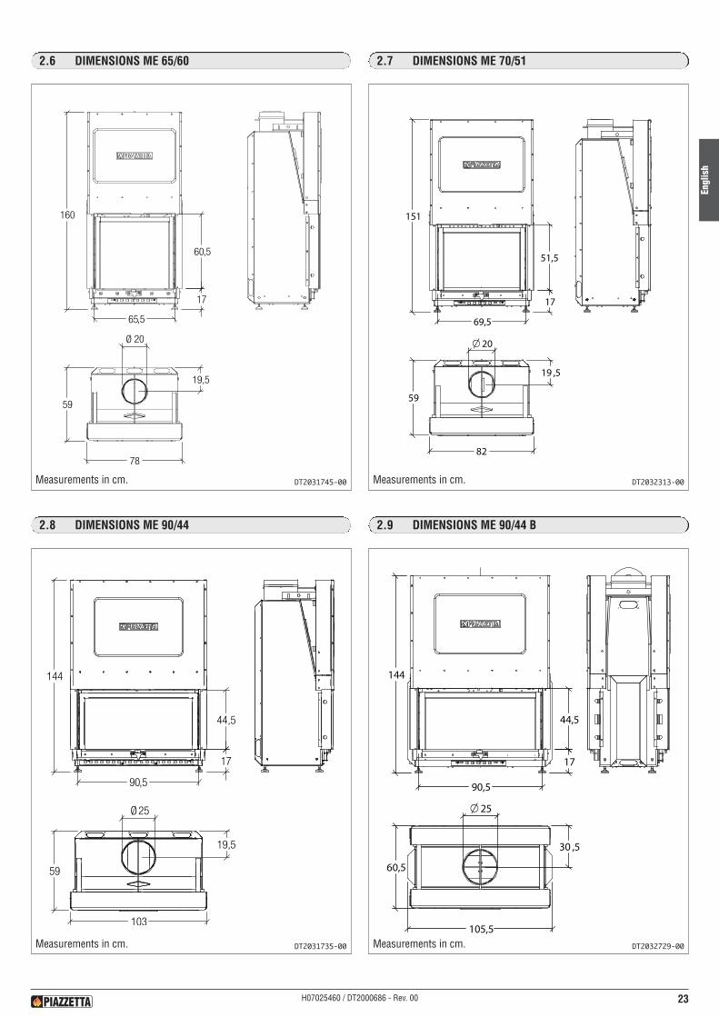
2.6 DIMENSIONS ME 65/60
DT2031745-00Measurements in cm.
2.8 DIMENSIONS ME 90/44
DT2031735-00Measurements in cm.
2.7 DIMENSIONS ME 70/51
151
17
51,5
69,5
82
59
19 ,5
20
DT2032313-00Measurements in cm.
2.9 DIMENSIONS ME 90/44 B
144
17
44,5
90,5
105,5
60,5
30 ,5
25
DT2032729-00Measurements in cm.
Engl
ish
24 H07025460 / DT2000686 - Rev. 00
DT1020235-01Measurements in cm.
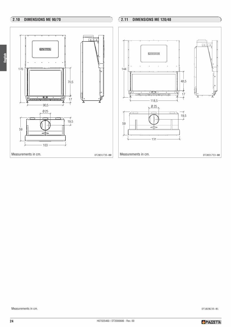
2.10 DIMENSIONS ME 90/70
DT2031735-00Measurements in cm.
2.11 DIMENSIONS ME 120/48
DT2031733-00Measurements in cm.
Engl
ish
25H07025460 / DT2000686 - Rev. 00
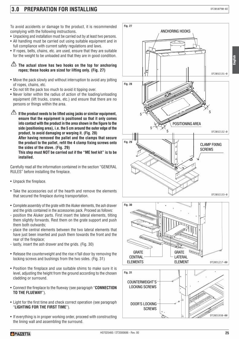
3.0 PREPARATION FOR INSTALLING DT2010790-02
To avoid accidents or damage to the product, it is recommendedcomplying with the following instructions.• Unpacking and installation must be carried out by at least two persons.• All handling must be carried out using suitable equipment and in
full compliance with current safety regulations and laws.• If ropes, belts, chains, etc. are used, ensure that they are suitable
for the weight to be unloaded and that they are in good condition.
The actual stove has two hooks on the top for anchoringropes; these hooks are sized for lifting only. (Fig. 27)
• Move the pack slowly and without interruption to avoid any joltingof ropes, chains, etc.
• Do not tilt the pack too much to avoid it tipping over.• Never loiter within the radius of action of the loading/unloading
equipment (lift trucks, cranes, etc.) and ensure that there are nopersons or things within the area.
If the product needs to be lifted using jacks or similar equipment,ensure that the equipment is positioned so that it only comesinto contact with the product in the area shown in the figure to theside (positioning area), i.e. the 5 cm around the outer edge of theproduct, to avoid damaging or warping it. (Fig. 28)After having removed the pallet and the clamps that securethe product to the pallet, refit the 4 clamp fixing screws ontothe sides of the stove. (Fig. 29)This step must NOT be carried out if the “ME feet kit” is to beinstalled.
Carefully read all the information contained in the section “GENERALRULES” before installing the fireplace.
• Unpack the fireplace.
• Take the accessories out of the hearth and remove the elementsthat secured the fireplace during transportation.
• Complete assembly of the grate with the Aluker elements, the ash drawerand the grids contained in the accessories pack. Proceed as follows:
- position the Aluker parts. First insert the lateral elements, tiltingthem slightly forwards. Rest them on the grate support and pushthem both outwards;
- place the central elements between the two lateral elements thathave just been inserted and push them towards the front and therear of the fireplace;
- lastly, insert the ash drawer and the grids. (Fig. 30)
• Release the counterweight and the rise n’fall door by removing thelocking screws and bushings from the two sides. (Fig. 31)
• Position the fireplace and use suitable shims to make sure it islevel, adjusting the height from the ground according to the chosencladding or surround.
• Connect the fireplace to the flueway (see paragraph “CONNECTIONTO THE FLUEWAY”).
• Light for the first time and check correct operation (see paragraph“LIGHTING FOR THE FIRST TIME”).
• If everything is in proper working order, proceed with constructingthe lining wall and assembling the surround.
GANCI ANCORAGGIOANCHORING HOOKSFig. 27
DT2032131-0
ZONA DI POSIZIONAMENTO
5
5
5
5
POSITIONING AREA
Fig. 28
DT2032132-0
VITI FISSAGGIOSTAFFE
CLAMP FIXINGSCREWS
Fig. 29
DT2032133-0
GRATECENTRAL
ELEMENTS
GRATELATERALELEMENT
Fig. 30
DT2031217-00
COUNTERWEIGHT’SLOCKING SCREWS
DOOR’S LOCKINGSCREWS
Fig. 31
DT2031938-00
Engl
ish
26 H07025460 / DT2000686 - Rev. 00
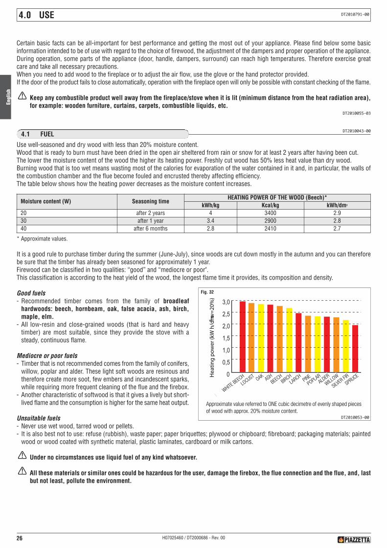
* Approximate values.
It is a good rule to purchase timber during the summer (June-July), since woods are cut down mostly in the autumn and you can thereforebe sure that the timber has already been seasoned for approximately 1 year.Firewood can be classified in two qualities: “good” and “mediocre or poor".This classification is according to the heat yield of the wood, the longest flame time it provides, its composition and density.
Good fuels- Recommended timber comes from the family of broadleafhardwoods: beech, hornbeam, oak, false acacia, ash, birch,maple, elm.
- All low-resin and close-grained woods (that is hard and heavytimber) are most suitable, since they provide the stove with asteady, continuous flame.
Mediocre or poor fuels- Timber that is not recommended comes from the family of conifers,
willow, poplar and alder. These light soft woods are resinous andtherefore create more soot, few embers and incandescent sparks,while requiring more frequent cleaning of the flue and the firebox.
- Another characteristic of softwood is that it gives a lively but short-lived flame and the consumption is higher for the same heat output.
Unsuitable fuels- Never use wet wood, tarred wood or pellets.- It is also best not to use: refuse (rubbish), waste paper; paper briquettes; plywood or chipboard; fibreboard; packaging materials; painted
wood or wood coated with synthetic material, plastic laminates, cardboard or milk cartons.
Under no circumstances use liquid fuel of any kind whatsoever.
All these materials or similar ones could be hazardous for the user, damage the firebox, the flue connection and the flue, and, lastbut not least, pollute the environment.
4.0 USE DT2010791-00
DT2010043-004.1 FUEL
Use well-seasoned and dry wood with less than 20% moisture content.Wood that is ready to burn must have been dried in the open air sheltered from rain or snow for at least 2 years after having been cut.The lower the moisture content of the wood the higher its heating power. Freshly cut wood has 50% less heat value than dry wood.Burning wood that is too wet means wasting most of the calories for evaporation of the water contained in it and, in particular, the walls ofthe combustion chamber and the flue become fouled and encrusted thereby affecting efficiency.The table below shows how the heating power decreases as the moisture content increases.
Certain basic facts can be all-important for best performance and getting the most out of your appliance. Please find below some basicinformation intended to be of use with regard to the choice of firewood, the adjustment of the dampers and proper operation of the appliance.During operation, some parts of the appliance (door, handle, dampers, surround) can reach high temperatures. Therefore exercise greatcare and take all necessary precautions.When you need to add wood to the fireplace or to adjust the air flow, use the glove or the hand protector provided.If the door of the product fails to close automatically, operation with the fireplace open will only be possible with constant checking of the flame.
Keep any combustible product well away from the fireplace/stove when it is lit (minimum distance from the heat radiation area),for example: wooden furniture, curtains, carpets, combustible liquids, etc.
DT2010055-03
FAGGIOBIANCO
ROBINA
QUERCIA
FRASSINO
FAGGIO
BETULLA
LARICEPINO
PIOPPO
ONTANOSALICE
ABETE BIANCO
ABETE ROSSO
Approximate value referred to ONE cubic decimetre of evenly shaped piecesof wood with approx. 20% moisture content.
Hea
ting
pow
er(k
Wh/
dm3w
=20%
)
WHITEBEEC
H
LOCUST
OAKASH
BIRCHLARCH
PINEPOPLAR
ALDER
BEECH
WILLOW
SILVER
FIR
SPRUCE
DT2010053-00
Moisture content (W) Seasoning timeHEATING POWER OF THE WOOD (Beech)*
kWh/kg Kcal/kg kWh/dm3
20 after 2 years 4 3400 2.930 after 1 year 3.4 2900 2.840 after 6 months 2.8 2410 2.7
Fig. 32

Engl
ish
27H07025460 / DT2000686 - Rev. 00
Log sizeThe size of the wood logs can also affect the efficiency of the product.It is essential for the wood to be arranged on the grate on top of alayer of embers.The logs must not touch the aluker or the glass window nor mustthey be put on top of each other. Place the wood as shown in thefigure 33.We therefore recommend using logs of the following size:- perimeter approx. 30/35 cm;- lwength approx. 20–25–30 cm according to the type of hearth.
Under no circumstances use liquid fuel of any kindwhatsoever.All these materials or similar ones could be hazardous for theuser, damage the firebox, the flue connection and the flue,and, last but not least, pollute the environment
Perimeter Lenght
Fig. 33
DT20300063-00
OPEN CLOSED
Fig. 34
DT2031181-00
DT2010792-014.2 SMOKE DAMPER REGULATION
(*) Position referred to a draught of 12 Pa
Whenever the fireplace is stoked with wood, the smoke damper automatically goes to the open position upon opening the door.After stoking the fire the damper must be returned manually to the position of operation.
When lighting the fireplace, put the smoke damper to the open posi-tion (fully to the left) until the bed of embers has been formed.This position is automatically adjusted upon opening the rise n’falldoor, the fireplace having been fitted with a mechanical smokedamper opening system connected to the actual door.Once the fireplace is properly lit, put the damper to the operating po-sition, which may vary according to the atmospheric conditions, thetype of flue andconsequently the draught. You will learn by trial anderror which is the best position for the smoke damper.
SMOKE DAMPER POSITIONFIREPLACE IN OPERATION AT NOMINAL POWER LIGHTING OR STOKING-UP OF FIREPLACE
ME 65/60 20 mm OPEN (*) OPENME 70/51 10 mm OPEN (*) OPENME 90/44 CLOSED OPENME 90/44 B - OPENME 90/70 CLOSED OPENME 120/48 4 mm OPEN (*) OPEN
Engl
ish
28 H07025460 / DT2000686 - Rev. 00
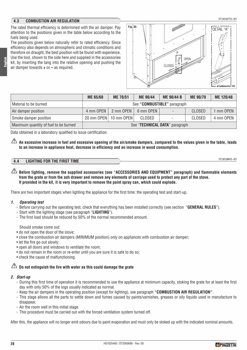
DT2010793-034.3 COMBUSTION AIR REGULATION
The rated thermal efficiency is determined with the air damper. Payattention to the positions given in the table below according to thefuels being used.The positions given below naturally refer to rated efficiency. Sinceefficiency also depends on atmospheric and climatic conditions andtherefore on draught, the best position will be found with experience.Use the tool, shown to the side here and supplied in the accessorieskit, by inserting the tang into the relative opening and pushing theair damper towards + or – as required.
DT2010045-034.4 LIGHTING FOR THE FIRST TIME
Before lighting, remove the supplied accessories (see “ACCESSORIES AND EQUIPMENT” paragraph) and flammable elementsfrom the grate or from the ash drawer and remove any elements of carriage used to protect any part of the stove.If provided in the kit, it is very important to remove the paint spray can, which could explode.
There are two important stages when lighting the appliance for the first time: the operating test and start-up.
1. Operating test- Before carrying out the operating test, check that everything has been installed correctly (see section “GENERAL RULES”).- Start with the lighting stage (see paragraph “LIGHTING”).- The first load should be reduced by 50% of the normal recommended amount.
Should smoke come out:• do not open the door of the stove;• close the combustion air dampers (MINIMUM position) only on appliances with combustion air damper;• let the fire go out slowly;• open all doors and windows to ventilate the room;• do not remain in the room or re-enter until you are sure it is safe to do so;• check the cause of malfunctioning.
Do not extinguish the fire with water as this could damage the grate
2. Start-up- During this first time of operation it is recommended to use the appliance at minimum capacity, stoking the grate for at least the first
day with only 50% of the logs usually indicated as normal.- Keep the air dampers in the operating position (except for lighting), see paragraph “COMBUSTION AIR REGULATION”.- This stage allows all the parts to settle down and fumes caused by paints/varnishes, greases or oily liquids used in manufacture to
disappear.- Air the room well in this initial stage.- This procedure must be carried out with the forced ventilation system turned off.
After this, the appliance will no longer emit odours due to paint evaporation and must only be stoked up with the indicated nominal amounts.
OPEN
CLOSED
DETAIL “A”Fig. 35
DT2031742-00
Data obtained in a laboratory qualified to issue certification.
An excessive increase in fuel and excessive opening of the air/smoke dampers, compared to the values given in the table, leadsto an increase in appliance heat, decrease in efficiency and an increase in wood consumption.
ME 65/60 ME 70/51 ME 90/44 ME 90/44 B ME 90/70 ME 120/48
Material to be burned See “COMBUSTIBLE” paragraph
Air damper position 4 mm OPEN 2 mm OPEN 6 mm OPEN - CLOSED 1 mm OPEN
Smoke damper position 20 mm OPEN 10 mm OPEN CLOSED - CLOSED 4 mm OPEN
Maximum quantity of fuel to be burned See “TECHNICAL DATA” paragraph
Engl
ish
29H07025460 / DT2000686 - Rev. 00
DT2030065-00
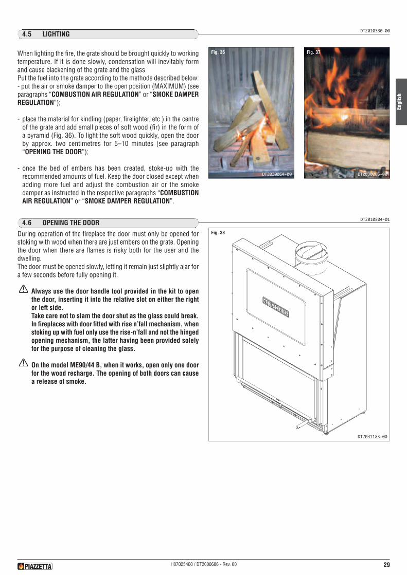
DT2010330-004.5 LIGHTING
DT2010804-014.6 OPENING THE DOOR
During operation of the fireplace the door must only be opened forstoking with wood when there are just embers on the grate. Openingthe door when there are flames is risky both for the user and thedwelling.The door must be opened slowly, letting it remain just slightly ajar fora few seconds before fully opening it.
Always use the door handle tool provided in the kit to openthe door, inserting it into the relative slot on either the rightor left side.Take care not to slam the door shut as the glass could break.In fireplaces with door fitted with rise n’fall mechanism, whenstoking up with fuel only use the rise-n’fall and not the hingedopening mechanism, the latter having been provided solelyfor the purpose of cleaning the glass.
On the model ME90/44 B, when it works, open only one doorfor the wood recharge. The opening of both doors can causea release of smoke.
Fig. 38
DT2031183-00
When lighting the fire, the grate should be brought quickly to workingtemperature. If it is done slowly, condensation will inevitably formand cause blackening of the grate and the glassPut the fuel into the grate according to the methods described below:- put the air or smoke damper to the open position (MAXIMUM) (seeparagraphs “COMBUSTION AIR REGULATION” or “SMOKE DAMPERREGULATION”);
- place the material for kindling (paper, firelighter, etc.) in the centreof the grate and add small pieces of soft wood (fir) in the form ofa pyramid (Fig. 36). To light the soft wood quickly, open the doorby approx. two centimetres for 5–10 minutes (see paragraph“OPENING THE DOOR”);
- once the bed of embers has been created, stoke-up with therecommended amounts of fuel. Keep the door closed except whenadding more fuel and adjust the combustion air or the smokedamper as instructed in the respective paragraphs “COMBUSTIONAIR REGULATION” or “SMOKE DAMPER REGULATION”.
Fig. 36
DT2030064-00
Fig. 37
Engl
ish
30 H07025460 / DT2000686 - Rev. 00
DT2010048-004.8 OPERATION UNDER ADVERSE WEATHER CONDITIONS
During the intermediate seasons with adverse weather conditions or when outdoor temperatures are higher, a sudden rise can causemalfunctioning of the draught, thereby impeding proper smoke discharge. In this case the grate must be loaded with only a little wood andthe primary air damper be set fully open so that the wood burns faster and thereby stabilises the draught.
DT2010051-004.9 OVERHEATING AND EXTINGUISHING
In the event of overheating or if some appliance parts or the flue turn red:- immediately stop the supply of fuel;- do not open the stove door;- close the air dampers (MINIMUM position);The fire will go out due to lack of air.
When the appliance has cooled down, find the cause of the problem and if necessary call in specialised personnel.
In the event of fire, extinguish with a fire extinguisher.
Do not extinguish the fire with water.
Air the room well before using it again in order to get rid of any smoke and combustion gases.
DT2010047-004.7 NIGHT TIME OPERATION AT MINIMUM
After normal operation during the day, the appliance may continue to operate for a few hours at night.When stoking up the fire for the last time in the evening, ensure that the bed of embers is sufficient, put the wood in the grate and then setthe combustion air dampers to minimum. Night time operation of the stove at minimum depends on the type of wood (a very hard wood isrecommended), the flue draught and the weather.The amount of wood to put on and the necessary adjustment of combustion air flow will be learned with experience (see the paragraph“COMBUSTION AIR REGULATION”).The next morning, start up the fire at maximum to burn off any creosote formed during the night. Creosote deposits start to form when theflue temperature falls to below 150 °C. To prevent this from happening it is important to try to maintain the grate of the appliance at normalworking temperature (rated heating efficiency phase) as long as possible.Prolonged operation of the stove at minimum could require more frequent cleaning of the grate and the flue.
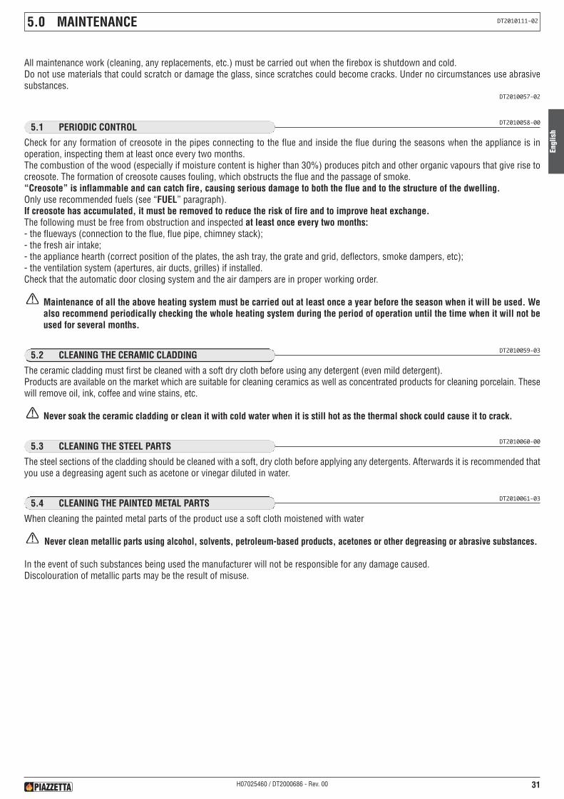
Engl
ish
31H07025460 / DT2000686 - Rev. 00
5.0 MAINTENANCE DT2010111-02
DT2010058-005.1 PERIODIC CONTROL
Check for any formation of creosote in the pipes connecting to the flue and inside the flue during the seasons when the appliance is inoperation, inspecting them at least once every two months.The combustion of the wood (especially if moisture content is higher than 30%) produces pitch and other organic vapours that give rise tocreosote. The formation of creosote causes fouling, which obstructs the flue and the passage of smoke.“Creosote” is inflammable and can catch fire, causing serious damage to both the flue and to the structure of the dwelling.Only use recommended fuels (see “FUEL” paragraph).If creosote has accumulated, it must be removed to reduce the risk of fire and to improve heat exchange.The following must be free from obstruction and inspected at least once every two months:- the flueways (connection to the flue, flue pipe, chimney stack);- the fresh air intake;- the appliance hearth (correct position of the plates, the ash tray, the grate and grid, deflectors, smoke dampers, etc);- the ventilation system (apertures, air ducts, grilles) if installed.Check that the automatic door closing system and the air dampers are in proper working order.
Maintenance of all the above heating system must be carried out at least once a year before the season when it will be used. Wealso recommend periodically checking the whole heating system during the period of operation until the time when it will not beused for several months.
DT2010059-035.2 CLEANING THE CERAMIC CLADDING
The ceramic cladding must first be cleaned with a soft dry cloth before using any detergent (even mild detergent).Products are available on the market which are suitable for cleaning ceramics as well as concentrated products for cleaning porcelain. Thesewill remove oil, ink, coffee and wine stains, etc.
Never soak the ceramic cladding or clean it with cold water when it is still hot as the thermal shock could cause it to crack.
DT2010060-005.3 CLEANING THE STEEL PARTS
The steel sections of the cladding should be cleaned with a soft, dry cloth before applying any detergents. Afterwards it is recommended thatyou use a degreasing agent such as acetone or vinegar diluted in water.
DT2010061-035.4 CLEANING THE PAINTED METAL PARTS
When cleaning the painted metal parts of the product use a soft cloth moistened with water
Never clean metallic parts using alcohol, solvents, petroleum-based products, acetones or other degreasing or abrasive substances.
In the event of such substances being used the manufacturer will not be responsible for any damage caused.Discolouration of metallic parts may be the result of misuse.
All maintenance work (cleaning, any replacements, etc.) must be carried out when the firebox is shutdown and cold.Do not use materials that could scratch or damage the glass, since scratches could become cracks. Under no circumstances use abrasivesubstances.
DT2010057-02
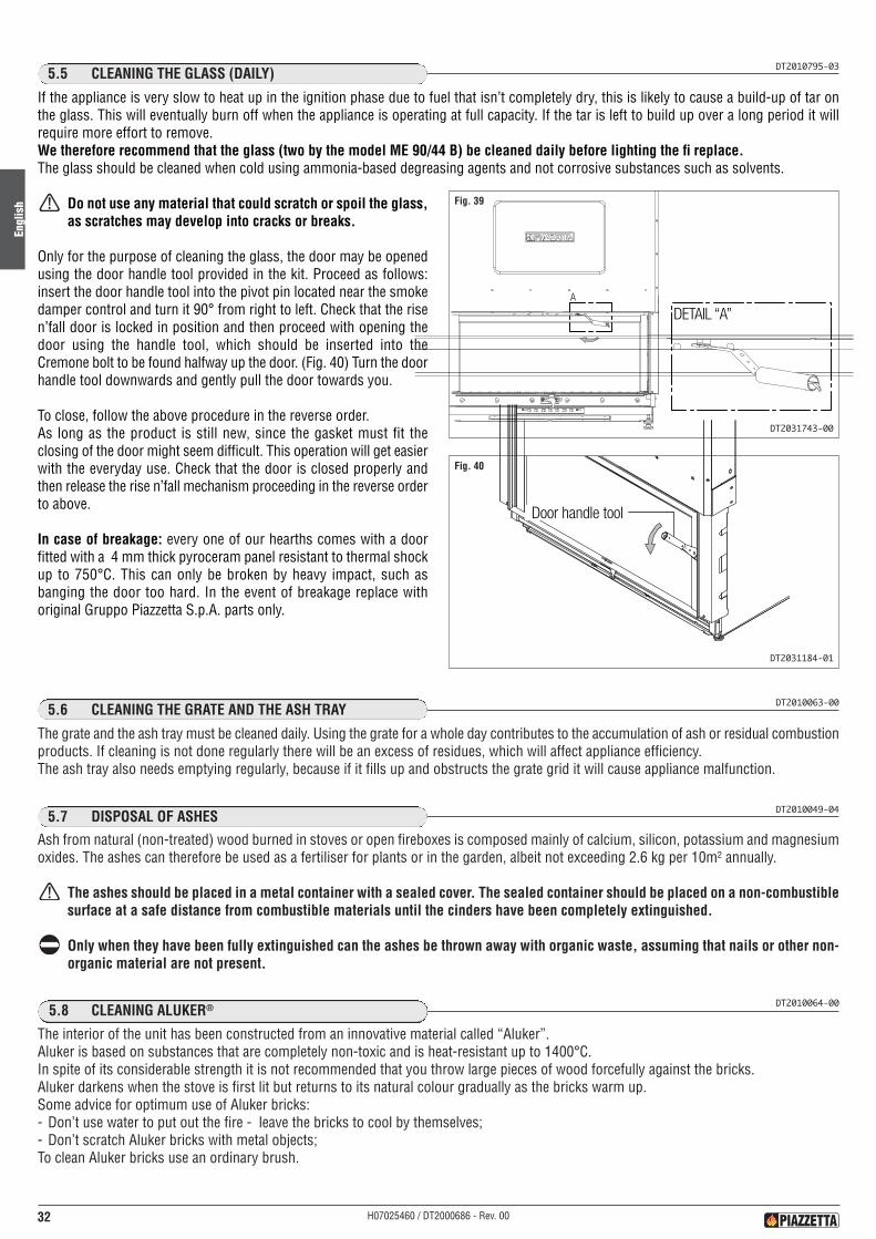
DT2010795-035.5 CLEANING THE GLASS (DAILY)
If the appliance is very slow to heat up in the ignition phase due to fuel that isn’t completely dry, this is likely to cause a build-up of tar onthe glass. This will eventually burn off when the appliance is operating at full capacity. If the tar is left to build up over a long period it willrequire more effort to remove.We therefore recommend that the glass (two by the model ME 90/44 B) be cleaned daily before lighting the fi replace.The glass should be cleaned when cold using ammonia-based degreasing agents and not corrosive substances such as solvents.
Do not use any material that could scratch or spoil the glass,as scratches may develop into cracks or breaks.
Only for the purpose of cleaning the glass, the door may be openedusing the door handle tool provided in the kit. Proceed as follows:insert the door handle tool into the pivot pin located near the smokedamper control and turn it 90° from right to left. Check that the risen’fall door is locked in position and then proceed with opening thedoor using the handle tool, which should be inserted into theCremone bolt to be found halfway up the door. (Fig. 40) Turn the doorhandle tool downwards and gently pull the door towards you.
To close, follow the above procedure in the reverse order.As long as the product is still new, since the gasket must fit theclosing of the door might seem difficult. This operation will get easierwith the everyday use. Check that the door is closed properly andthen release the rise n’fall mechanism proceeding in the reverse orderto above.
In case of breakage: every one of our hearths comes with a doorfitted with a 4 mm thick pyroceram panel resistant to thermal shockup to 750°C. This can only be broken by heavy impact, such asbanging the door too hard. In the event of breakage replace withoriginal Gruppo Piazzetta S.p.A. parts only.
Engl
ish
32 H07025460 / DT2000686 - Rev. 00
Door handle tool
Fig. 40
DT2031184-01
DETAIL “A”
Fig. 39
DT2031743-00
DT2010049-045.7 DISPOSAL OF ASHES
Ash from natural (non-treated) wood burned in stoves or open fireboxes is composed mainly of calcium, silicon, potassium and magnesiumoxides. The ashes can therefore be used as a fertiliser for plants or in the garden, albeit not exceeding 2.6 kg per 10m2 annually.
The ashes should be placed in a metal container with a sealed cover. The sealed container should be placed on a non-combustiblesurface at a safe distance from combustible materials until the cinders have been completely extinguished.
Only when they have been fully extinguished can the ashes be thrown away with organic waste, assuming that nails or other non-organic material are not present.
DT2010063-005.6 CLEANING THE GRATE AND THE ASH TRAY
The grate and the ash tray must be cleaned daily. Using the grate for a whole day contributes to the accumulation of ash or residual combustionproducts. If cleaning is not done regularly there will be an excess of residues, which will affect appliance efficiency.The ash tray also needs emptying regularly, because if it fills up and obstructs the grate grid it will cause appliance malfunction.
DT2010064-005.8 CLEANING ALUKER®
The interior of the unit has been constructed from an innovative material called “Aluker”.Aluker is based on substances that are completely non-toxic and is heat-resistant up to 1400°C.In spite of its considerable strength it is not recommended that you throw large pieces of wood forcefully against the bricks.Aluker darkens when the stove is first lit but returns to its natural colour gradually as the bricks warm up.Some advice for optimum use of Aluker bricks:- Don’t use water to put out the fire - leave the bricks to cool by themselves;- Don’t scratch Aluker bricks with metal objects;To clean Aluker bricks use an ordinary brush.

Engl
ish
33H07025460 / DT2000686 - Rev. 00
DT2010791-015.9 REMOVING THE SMOKE BAFFLE PLATES
The fi replace is fi tted inside above the grate with a baffl e plate,which has the function of defl ecting the route taken by the smokethereby increasing the heat exchange surface area. In the ME120/48model there are 2 baffl e plates.The baffl e plate rests on two supports that can be seen in the fi gure.To remove the baffl e plate/s, push it/them upwards at the rear sothat it/them comes/come out of the front support and then drawit/them out from below.
Proceed with great care to avoid the baffle plate/s falling on theAluker grate.
Clean and then replace, following the above procedure in the reverseorder.
Front baffle platesupport
Rear baffle platesupport
Fig. 41
DT2031185-01
DT2010065-015.10 CLEANING THE FAN (ONCE A YEAR)
All cleaning and maintenance operations must be carried out after DISCONNECTION OF THE POWER.
Pursuant to current regulations on the safety of electrical equipment, you must contact a Piazzetta After-Sales Service Centre or aqualified electrician for all and any work connected with installation, maintenance or servicing that involves access to electrical parts.
Dust can accumulate in the ventilation kit and in particular in the holes of the protective cover of the fan, the grilles and the fan blade, whichshould therefore be cleaned once a year. Use a vacuum cleaner or compressed air, being careful with the electrical parts.The ventilation kit must be disassembled for proper cleaning. Follow the installation procedure in the reverse order (see the instructionsenclosed in the kit).
DT2010068-005.11 SHUTTING DOWN
Before any long period during which the firebox will be inactive we recommend that you carry out a thorough cleaning, thereby avoidingencrustations and oxidations which will be difficult to clean later. We also recommend that as a preventative measure you carry out a generalcheckup as outlined in the paragraph headed “PERIODIC CHECKS”.
After a period of inactivity problems relating to the expansion of parts or the release of odorous gases may arise. We therefore recommendthat upon restarting the unit you do not immediately run it at full power. Nor should you activate the ventilation system until the odorous gaseshave dispersed. This problem can be dealt with by simply airing the room.
DT2010379-015.12 CLOSING DOOR SYSTEM
This operation should be carried out by specialised personnel.
The “rise n’fall” door closing system must be checked periodically, at least once every two years; attention must be paid in particular tolubricating the roller located inside the double glazing or, depending on the model, the pulleys located outside the double glazing.
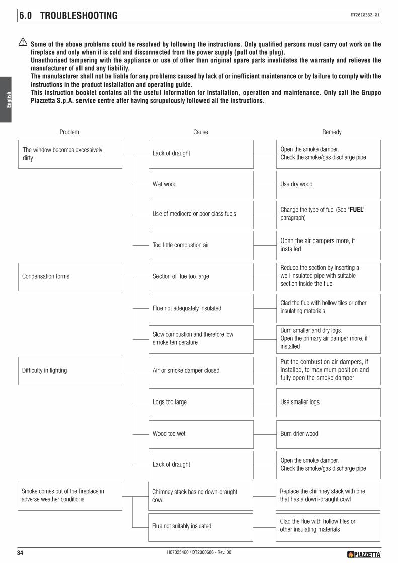
Engl
ish
34 H07025460 / DT2000686 - Rev. 00
Some of the above problems could be resolved by following the instructions. Only qualified persons must carry out work on thefireplace and only when it is cold and disconnected from the power supply (pull out the plug).Unauthorised tampering with the appliance or use of other than original spare parts invalidates the warranty and relieves themanufacturer of all and any liability.The manufacturer shall not be liable for any problems caused by lack of or inefficient maintenance or by failure to comply with theinstructions in the product installation and operating guide.This instruction booklet contains all the useful information for installation, operation and maintenance. Only call the GruppoPiazzetta S.p.A. service centre after having scrupulously followed all the instructions.
6.0 TROUBLESHOOTING DT2010332-01
ydemeResuaCmelborP
The window becomes excessivelydirty
Lack of draughtOpen the smoke damper.
Check the smoke/gas discharge pipe
Wet wood Use dry wood
Use of mediocre or poor class fuelsChange the type of fuel (See “FUEL”paragraph)
Too little combustion airOpen the air dampers more, ifinstalled
Condensation forms Section of flue too largeReduce the section by inserting awell insulated pipe with suitablesection inside the flue
Flue not adequately insulatedClad the flue with hollow tiles or otherinsulating materials
Slow combustion and therefore lowsmoke temperature
Burn smaller and dry logs.Open the primary air damper more, ifinstalled
Difficulty in lighting Air or smoke damper closedPut the combustion air dampers, ifinstalled, to maximum position andfully open the smoke damper
Logs too large Use smaller logs
Wood too wet Burn drier wood
Lack of draughtOpen the smoke damper.
Check the smoke/gas discharge pipe
Smoke comes out of the fireplace inadverse weather conditions
Chimney stack has no down-draughtcowl
Replace the chimney stack with onethat has a down-draught cowl
Flue not suitably insulatedClad the flue with hollow tiles orother insulating materials

Engl
ish
35H07025460 / DT2000686 - Rev. 00
(*) Pursuant to current regulations on the safety of electrical equipment, you must contact a Piazzetta After-Sales Service Centreor a qualified electrician for all and any work connected with installation, maintenance or servicing that involves access toelectrical parts.
ydemeResuaCmelborP
Insufficient heatQuantity of wood less thannecessary for nominal efficiency
Use the quantity of wood indicatedin the instructions (see “TECHNICALDATA” paragraph)
Undersized grate for theenvironment to be heated
Integrate with another product
Inadequate insulation for theenvironment in which the fireplaceis installed
Insulate well with suitable materials
Oversized fresh air intake Decrease the intake section
The fan does not work (*) Incorrect connection to power supplyCorrect the connection according tothe assembly diagram
Electronic regulator damaged Replace the regulator
Power failure Power the appliance
Too little and only lukewarm air flowsfrom the outlets Pipework not insulated Suitably insulate
Pipework too long or with too manybends
Change the path, complying withthe ventilation kit instruction booklet
Too many branches Change the path
Environment too large for capacity ofthe fan and power of the fireplace
Heat fewer rooms or use thefireplace as integration
Noisy fan (*) Presence of dust or similar in the fan Clean the fan
Vibrations Check fan position
Worn rotating parts Replace the fan
Smoke comes out upon openingthe door Door opened too fast
Keep the door just ajar for a fewseconds before fully opening
There are still flamesOnly open the door when just embersremain in the grate
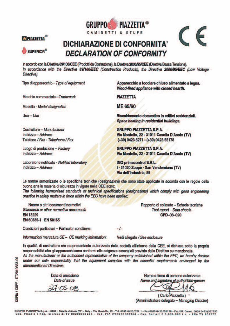

41H07025460 / DT2000686 - Rev. 00

42 H07025460 / DT2000686 - Rev. 00

43H07025460 / DT2000686 - Rev. 00
UK
ww
w.m
iotto
.itG
rupp
oPi
azze
ttaS.
p.A.
Tech
nica
lDep
artm
ent-
cod.
H07
0254
60/D
T200
0686
-Rev
.00
-(10
/201
0)
Via Montello, 2231011 Casella d’Asolo (TV) - ITALY
Tel. +39.04235271 - Fax +39.042355178www.piazzetta.it
e-mail: [email protected]
Product serial number, to be quoted when requesting servicefrom the Gruppo Piazzetta After-Sales Service Centre.


![0cmEffective nuclear theories and lattice QCD · 50 100 150 200 250 300 10 20 30 40 50 60 70 80 90 100 B [Me V] B t [Me V] exp erimen t m = 137 Me V m = 510 Me V m = 805 Me V!K. The](https://img.pdfslide.us/doc/110x75/6008f13d3ea577381d6af11a/0cmeffective-nuclear-theories-and-lattice-qcd-50-100-150-200-250-300-10-20-30-40.jpg)


![Untitled-2 [] · TS EN 442/2 -At 600C (90/70-200C) Tip nurnarasl ME 300 ME 375 ME 450 ME 525 ME 600 ME 750 ME 825 ME 900 ME 1000 ME 1250 Yükseklik (mm) 300 375 450 525 600 750 825](https://img.pdfslide.us/doc/110x75/5e0d798db38638567d2914f4/untitled-2-ts-en-4422-at-600c-9070-200c-tip-nurnarasl-me-300-me-375-me.jpg)


![Compound, [TpBut ]MgF: Hydrogen Bonding, Halogen Bonding ... · lyophilized to afford [TpBut,Me]MgF as a white powder (90 mg, 89% yield). Colorless Colorless crystals of [Tp But,Me](https://img.pdfslide.us/doc/110x75/5b956ef509d3f2205c8cc39a/compound-tpbut-mgf-hydrogen-bonding-halogen-bonding-lyophilized-to.jpg)