Embed Size (px)
Citation preview
ROHM MarketingUSA
H-bridge Driver Seriesfor brush motors
Motor Drivers
<Portable <Automotive <Appl iances <Medical
Selection Guide
Innovat ions Embedded
1.888.775.ROHM CNA09014
H-bridge Driversfrom ROHM Semiconductor
DC brush motors are simple, reliable and low-
cost. And now, to achieve the best possible
performance and design flexibility, ROHM
offers a complete line of H-bridge drivers for
DC brush motors that combine a selection
of analog and digital input control strategies
with advanced, high-efficiency PWM motor
speed control output. These powerful new
ICs provide a unique VREF to PWM conversion
circuit that can quickly transform an exisitng
analog speed control design into a high-
performance, low power PWM configuration -
sometimes by simply replacing the IC! Inputs
are also provided for direct digital (PWM)
control from an external MCU or other motor
control device.
ROHM H-bridge ICs combine BiCMOS
control and power MOSFET outputs to deliver
exceptional performance with minimal external
components, virtually zero standby current
and high operating efficiency.
Fully integrated circuit protection is also
provided, including: n Internal shoot through protection
n ESD protection
n fault protection (current, voltage, temp)
The ROHM H-bridge drive product line is
offered with pin-compatible devices optimized
for 7 V, 18 V and 36 V maximum supply
voltages to optimize power consumption; and
in single and dual channel configurations.
These latest ROHM H-bridge ICs are pin-
compatible with earlier (linear output) models
making it possble to migrate to PWM control
without any modifications to the PCB layout.
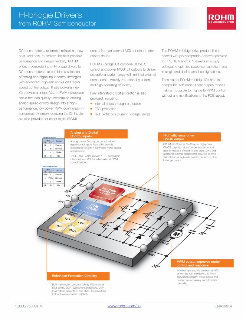
High efficiency driveCMOS output
ROHM’s P-Channel / N-Channel high-power CMOS output provides low on resistance and also eliminates the need for a charge pump and additional external components required to drive the N-Channel high-side switch common in other H-bridge drivers.
PWM output improves motor control and response
Whether operated via an external MCU or with the ICs’ internal VREF to PWM conversion circuitry, motor speed and position are accurately and efficiently controlled.
Enhanced Protection Circuitry
Built-in protection circuits such as TSD (thermal shut down), OCP (overcurrent protection), OVP (overvoltage protection), and UVLO (undervoltage lock out) assure system reliability.
FINInput Output
Forward
Reverse
Brake
Idle
RINPWM L
L PWM
H H
L L
Direct PWM control
FINInput Output
Forward
Reverse
Brake
Idle
RINH L
L H
H H
L L
VREF input control
Analog and Digital Control Inputs
Analog control (VREF) inputs combined with digital control inputs FIN and RIN provide exceptional flexibilty in controlling motor speed and direction.
The FIN and RIN also provide a TTL-compatible interface to an MCU or other external PWM control device.
www.rohm.com/us
1.888.775.ROHM CNA09014
H-bridge Driver Seriesfrom ROHM Semiconductor
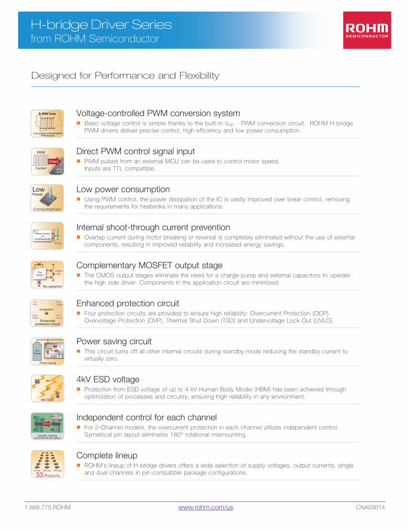
Voltage-controlled PWM conversion systemn Basic voltage control is simple thanks to the built-in VREF - PWM conversion circuit. ROHM H-bridge
PWM drivers deliver precise control, high efficiency and low power consumption.
Direct PWM control signal inputn PWM pulses from an external MCU can be used to control motor speed.
Inputs are TTL compatible.
Low power consumptionn Using PWM control, the power dissipation of the IC is vastly improved over linear control, removing
the requirements for heatsinks in many applications.
Internal shoot-through current preventionn Overlap current during motor breaking or reversal is completely eliminated without the use of external
components, resulting in improved reliability and increased energy savings.
Complementary MOSFET output stage n The CMOS output stages eliminate the need for a charge pump and external capacitors to operate
the high side driver. Components in the application circuit are minimized.
Enhanced protection circuitn Four protection circuits are provided to ensure high reliability: Overcurrent Protection (OCP),
Overvoltage Protection (OVP), Thermal Shut Down (TSD) and Undervoltage Lock Out (UVLO).
Power saving circuitn This circuit turns off all other internal circuits during standby mode reducing the standby current to
virtually zero.
4kV ESD voltagen Protection from ESD voltage of up to 4 kV Human Body Model (HBM) has been achieved through
optimization of processes and circuitry, ensuring high reliability in any environment.
Independent control for each channel n For 2-Channel models, the overcurrent protection in each channel utilizes independent control.
Symetrical pin layout eliminates 180° rotational mismounting.
Complete lineupn ROHM’s lineup of H-bridge drivers offers a wide selection of supply voltages, output currents, single
and dual channels in pin-compatible package configurations.
No capacitor
PreDriver
CMOS
VCC
A little loss
Low power consumptionPWM drive
PWM
Control
Direct
MotorDriver
Low Power
C o n s u m p t i o n
STOP
OUT
VCC
Never turnedon
simultaneously
Enhancedprotection circuit
Overvoltage
Overcurrent
Overheat
Undervoltage
protection
LowPower
Power saving
C B
APowerSave
4kV
4kV ESD
Counter rotatingsymmetrical pin layout
MISMOUNT
Noproblem!
Noproblem!
18 Products33 Products
7V max. 18V max. 36V max.
Designed for Performance and Flexibility
www.rohm.com/us
1.888.775.ROHM CNA09014
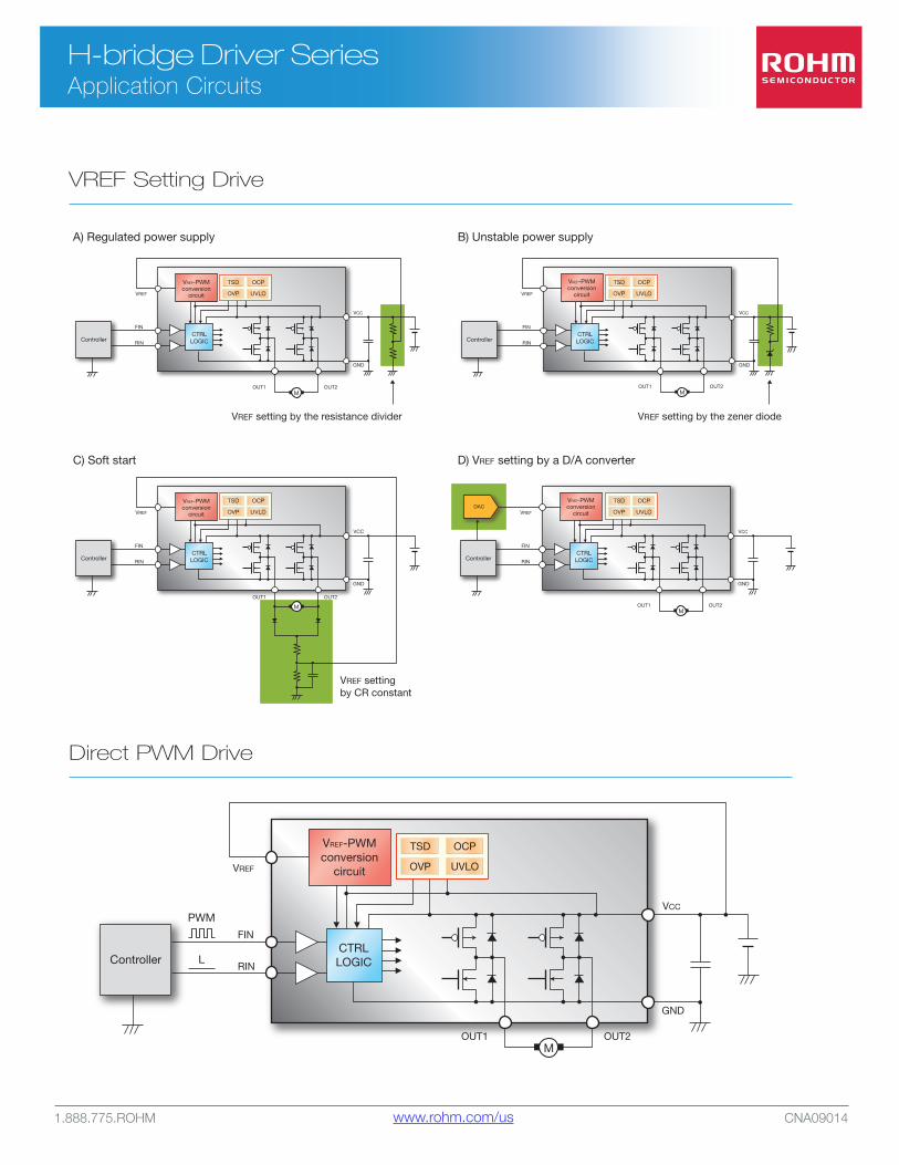
H-bridge Driver SeriesApplication Circuits
A) Regulated power supply B) Unstable power supply
C) Soft start D) VREF setting by a D/A converter
ControllerCTRLLOGIC
VCC
FIN
VREF
RIN
GND
OUT2OUT1M
ControllerCTRLLOGIC
VCC
FIN
RIN
GND
OUT2OUT1
ControllerCTRLLOGIC
VCC
FIN
VREF
RIN
GND
OUT2OUT1M
ControllerCTRLLOGIC
DAC
VCC
FIN
VREF
RIN
GND
OUT2OUT1M
VREF setting by the resistance divider
VREF settingby CR constant
VREF setting by the zener diode
M
VREF
TSD OCP
OVP UVLO
TSD OCP
OVP UVLO
TSD OCP
OVP UVLO
TSD OCP
OVP UVLO
VREF-PWMconversion
circuit
VREF-PWMconversion
circuit
VREF-PWMconversion
circuit
VREF-PWMconversion
circuit
ControllerCTRLLOGIC
VCC
FIN
VREF
RIN
GND
OUT2OUT1M
L
PWM
TSD OCP
OVP UVLO
VREF-PWMconversion
circuit
VREF Setting Drive
Direct PWM Drive
www.rohm.com/us
1.888.775.ROHM CNA09014
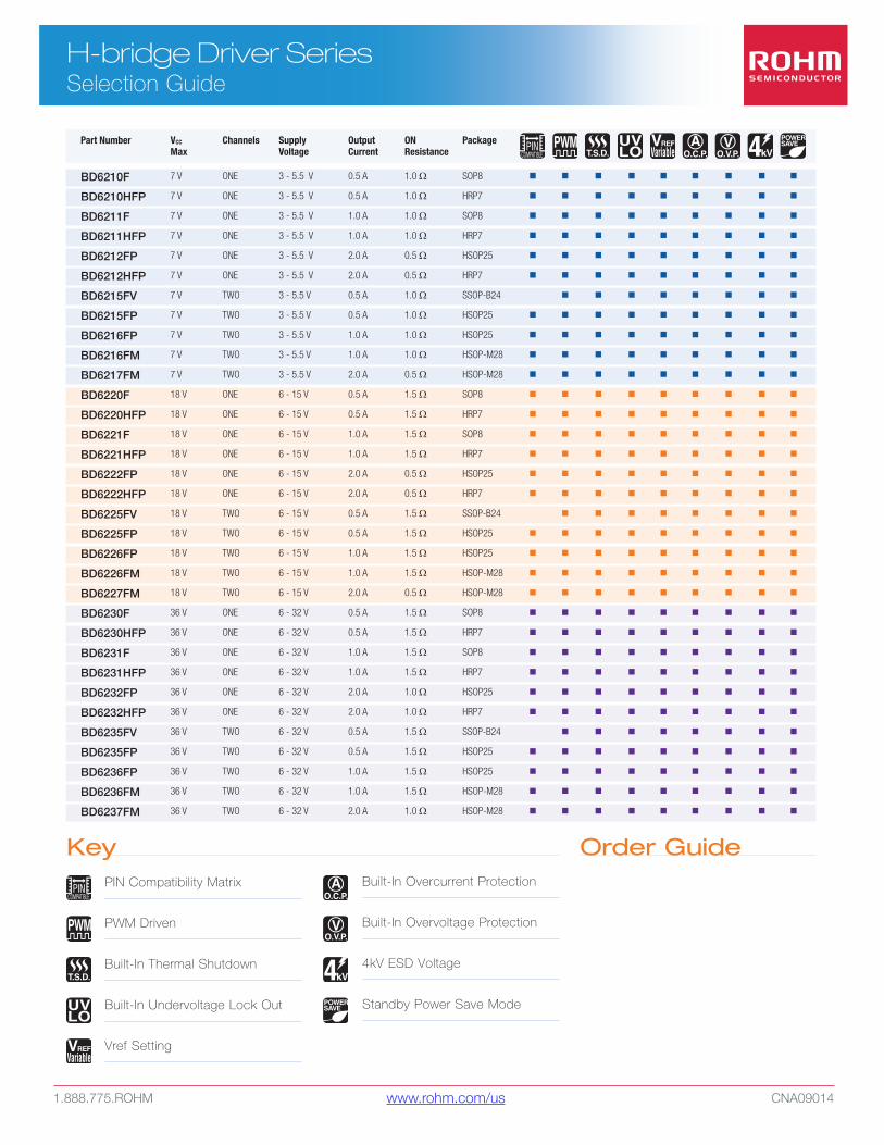
H-bridge Driver SeriesSelection Guide
Part Number VCC Channels Supply Output ON Package Max Voltage Current Resistance
BD6210F 7 V ONE 3 - 5.5 V 0.5 A 1.0 W SOP8 n n n n n n n n n
BD6210HFP 7 V ONE 3 - 5.5 V 0.5 A 1.0 W HRP7 n n n n n n n n n
BD6211F 7 V ONE 3 - 5.5 V 1.0 A 1.0 W SOP8 n n n n n n n n n
BD6211HFP 7 V ONE 3 - 5.5 V 1.0 A 1.0 W HRP7 n n n n n n n n n
BD6212FP 7 V ONE 3 - 5.5 V 2.0 A 0.5 W HSOP25 n n n n n n n n n
BD6212HFP 7 V ONE 3 - 5.5 V 2.0 A 0.5 W HRP7 n n n n n n n n n
BD6215FV 7 V TWO 3 - 5.5 V 0.5 A 1.0 W SSOP-B24 n n n n n n n n
BD6215FP 7 V TWO 3 - 5.5 V 0.5 A 1.0 W HSOP25 n n n n n n n n n
BD6216FP 7 V TWO 3 - 5.5 V 1.0 A 1.0 W HSOP25 n n n n n n n n n
BD6216FM 7 V TWO 3 - 5.5 V 1.0 A 1.0 W HSOP-M28 n n n n n n n n n
BD6217FM 7 V TWO 3 - 5.5 V 2.0 A 0.5 W HSOP-M28 n n n n n n n n n
BD6220F 18 V ONE 6 - 15 V 0.5 A 1.5 W SOP8 n n n n n n n n n
BD6220HFP 18 V ONE 6 - 15 V 0.5 A 1.5 W HRP7 n n n n n n n n n
BD6221F 18 V ONE 6 - 15 V 1.0 A 1.5 W SOP8 n n n n n n n n n
BD6221HFP 18 V ONE 6 - 15 V 1.0 A 1.5 W HRP7 n n n n n n n n n
BD6222FP 18 V ONE 6 - 15 V 2.0 A 0.5 W HSOP25 n n n n n n n n n
BD6222HFP 18 V ONE 6 - 15 V 2.0 A 0.5 W HRP7 n n n n n n n n n
BD6225FV 18 V TWO 6 - 15 V 0.5 A 1.5 W SSOP-B24 n n n n n n n n
BD6225FP 18 V TWO 6 - 15 V 0.5 A 1.5 W HSOP25 n n n n n n n n n
BD6226FP 18 V TWO 6 - 15 V 1.0 A 1.5 W HSOP25 n n n n n n n n n
BD6226FM 18 V TWO 6 - 15 V 1.0 A 1.5 W HSOP-M28 n n n n n n n n n
BD6227FM 18 V TWO 6 - 15 V 2.0 A 0.5 W HSOP-M28 n n n n n n n n n
BD6230F 36 V ONE 6 - 32 V 0.5 A 1.5 W SOP8 n n n n n n n n n
BD6230HFP 36 V ONE 6 - 32 V 0.5 A 1.5 W HRP7 n n n n n n n n n
BD6231F 36 V ONE 6 - 32 V 1.0 A 1.5 W SOP8 n n n n n n n n n
BD6231HFP 36 V ONE 6 - 32 V 1.0 A 1.5 W HRP7 n n n n n n n n n
BD6232FP 36 V ONE 6 - 32 V 2.0 A 1.0 W HSOP25 n n n n n n n n n
BD6232HFP 36 V ONE 6 - 32 V 2.0 A 1.0 W HRP7 n n n n n n n n n
BD6235FV 36 V TWO 6 - 32 V 0.5 A 1.5 W SSOP-B24 n n n n n n n n
BD6235FP 36 V TWO 6 - 32 V 0.5 A 1.5 W HSOP25 n n n n n n n n n
BD6236FP 36 V TWO 6 - 32 V 1.0 A 1.5 W HSOP25 n n n n n n n n n
BD6236FM 36 V TWO 6 - 32 V 1.0 A 1.5 W HSOP-M28 n n n n n n n n n
BD6237FM 36 V TWO 6 - 32 V 2.0 A 1.0 W HSOP-M28 n n n n n n n n n
Key Order GuidePIN Compatibility Matrix
PWM Driven
Built-In Thermal Shutdown
Built-In Undervoltage Lock Out
Vref Setting
Built-In Overcurrent Protection
Built-In Overvoltage Protection
4kV ESD Voltage
Standby Power Save Mode
www.rohm.com/us
1.888.775.ROHM CNA09014
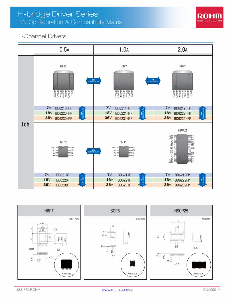
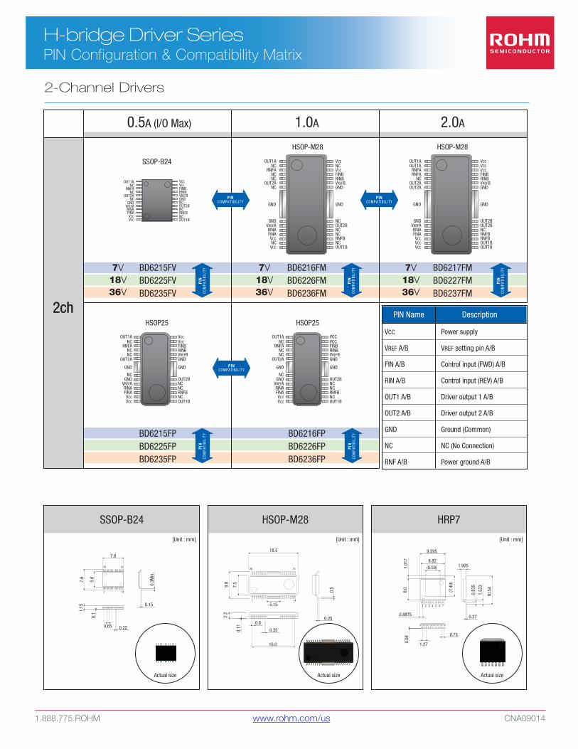
H-bridge Driver SeriesPIN Configuration & Compatibility Matrix
0.5A 1.0A 2.0A
BD6230HFP
BD6230F
BD6231HFP
BD6231F
BD6232HFP
BD6232FP
VCC
RINGND
FIN
OUT2
OUT1
VREF
GNDOUT2VREF
RIN
OUT1VCC
VCC
FIN
OUT1OUT1
NCNCNC
GND
RNFRNFNCNCNC
OUT2OUT2
GND
NCNCVCCVCCVCCFIN
RINNCVREFNCNCNC
GND
BD6220HFP
BD6220F
BD6221HFP
BD6221F
BD6222HFP
BD6222FP
BD6210HFP
BD6210F
BD6211HFP
BD6211F
BD6212HFP
BD6212FP
HRP7
SOP8 SOP8
HSOP25
VCC
RINGND
FIN
OUT2
OUT1
VREF
HRP7
VCC
RINGND
FIN
OUT2
OUT1
VREF
HRP7
GNDOUT2VREF
RIN
OUT1VCC
VCC
FIN
SOP8
0.3M
in.
0.15
0.4
0.11
6.2
4.4
5.0
8 5
41
1.27
1.5
Actual size
[Unit : mm]
HSOP25
7.8
5.4
2.75
1.95
25 14
1 13
0.11
1.9
0.36
0.3M
in.
0.25
13.6
0.8
Actual size
[Unit : mm]
1ch1ch
7V18V36V
7V18V36V
7V18V36V
7V18V36V
7V18V36V
7V18V36V
PINCOMPATIB IL ITY
PIN
COM
PATI
BILI
TY
PIN
COM
PATI
BILI
TY
PIN
COM
PATI
BILI
TY
PIN
COM
PATI
BILI
TY
PIN
COM
PATI
BILI
TY
PIN
COM
PATI
BILI
TY
PINCOMPATIB IL ITY
PINCOMPATIB IL ITY
HRP7
7654321
0.73
1.27
0.8875
1.905
0.83
5
1.52
3
10.5
4
0.27
0.08
9.395
8.82(5.59)1.
017
8.0
(7.4
9)
Actual size
[Unit : mm]
1-Channel Drivers
www.rohm.com/us
1.888.775.ROHM CNA09014
H-bridge Driver SeriesPIN Configuration & Compatibility Matrix
VCCVCC
VCCNCVCCFINBRINBVREFBGND
NCOUT2BNCNCRNFBNCOUT1B
OUT1ANC
RNFANCNC
OUT2ANC
GNDVREFARINAFINAVCCNCVCC
GNDGND
FINBRINBVREFBGNDNCOUT2BNCRNFBNCOUT1B
OUT1ANC
OUT1ANC
RNFANCNC
OUT2A
NCGND
VREFARINAFINAVCCVCC
GND
VCCVCCFINBRINBVREFBGND
OUT2BNCNCRNFBNCOUT1B
GND
RNFANC
OUT2ANC
GNDVREFARINAFINAVCCVCC
BD6235FV
BD6235FP
BD6236FM
BD6236FP
BD6237FMBD6225FV
BD6225FP
BD6226FM
BD6226FP
BD6227FMBD6215FV7V
18V36V
7V18V36V
7V18V36V
SSOP-B24
HSOP-M28
HSOP25 HSOP25
HSOP-M28
BD6215FP
BD6216FM
BD6216FP
BD6217FM
OUT1ANC
RNFANCNC
OUT2A
NCGND
VREFARINAFINAVCCVCC
GND
VCCVCCFINBRINBVREFBGND
OUT2BNCNCRNFBNCOUT1B
GND
VCCVCCVCCFINBRINBVREFBGND
OUT2BOUT2BNCRNFBRNFBOUT1BOUT1B
OUT1AOUT1A
RNFARNFA
NCOUT2AOUT2A
GNDVREFARINAFINAVCCVCCVCC
GNDGND
VCC
VREF A/B
FIN A/B
RIN A/B
OUT1 A/B
OUT2 A/B
GND
NC
RNF A/B
Power supply
VREF setting pin A/B
Control input (FWD) A/B
Control input (REV) A/B
Driver output 1 A/B
Driver output 2 A/B
Ground (Common)
NC (No Connection)
Power ground A/B
PIN Name Description
0.5A (I/O Max) 1.0A 2.0A
HSOP-M28
Actual size
18.5
7.5
9.9
28 15
1 14
2.2
0.35
5.15
0.5
0.80.25
16.0
0.11
[Unit : mm]
2ch2ch
HRP7
7654321
0.73
1.27
0.8875
1.905
0.83
5
1.52
3
10.5
4
0.27
0.08
9.395
8.82(5.59)1.
017
8.0
(7.4
9)
Actual size
[Unit : mm]
PINCOMPATIB IL ITY
PINCOMPATIB IL ITY
PINCOMPATIB IL ITY
PIN
COM
PATI
BILI
TYPI
NCO
MPA
TIBI
LITY
PIN
COM
PATI
BILI
TYPI
NCO
MPA
TIBI
LITY
PIN
COM
PATI
BILI
TY
SSOP-B24
0.15
1.15
0.1
1
0.65
7.8
7.6
5.6
24
0.3M
in.
12
13
0.22
Actual size
[Unit : mm]
2-Channel Drivers
www.rohm.com/us

NOTE: For the most current product information, contact a ROHM sales representative in your area.
ROHM assumes no responsibility for the use of any circuits described herein, conveys no license under any patent or other right, and makes no representations that the circuits are free from patent infringement. Specifications subject to change without notice for the purpose of improvement.
The products listed in this catalog are designed to be used with ordinary electronic equipment or devices (such as audio visual equipment, office-automation equipment, communications devices, electrical appliances and electronic toys). Should you intend to use these products with equipment or devices which require an extremely high level of reliability and the malfunction of which would directly endanger human life (such as medical instruments, transportation equipment, aerospace machinery, nuclear-reactor controllers, fuel controllers and other safety devices), please be sure to consult with our sales representative in advance.
© 2009 ROHM Semiconductor USA, LLC. Although every effort has been made to ensure accuracy, ROHM accepts no responsibility for errors or omissions. Specifications and product availability may be revised without notice. No part of this document represents an offer or contract. Industry part numbers, where specified, are given as an approximate comparative guide to circuit function only. Consult ROHM prior to use of components in safety, health or life-critical systems. All trademarks acknowledged.
www.rohm.com/us | 1.888.775.ROHM
ROHM Semiconductor USA, LLC
6815 Flanders Drive, Suite 150
San Diego, CA 92121


![[NE Handbook series ] Power Devices - Rohmrohmfs.rohm.com/en/products/databook/catalog/common/handbook_po… · 2 PR 3 Power Device ROHM Semiconductor continues to increase its Portfolio](https://img.pdfslide.us/doc/110x75/5a753a5c7f8b9aea3e8c57aa/ne-handbook-series-power-devices-rohmrohmfsrohmcomenproductsdatabookcatalogcommonhandbookpo.jpg)