Embed Size (px)
Citation preview
H ∞ active anti-roll bar control to prevent rollover of
heavy vehicles: a robustness analysis
Van-Tan Vu, Olivier Sename, Luc Dugard, Peter Gaspar
To cite this version:
Van-Tan Vu, Olivier Sename, Luc Dugard, Peter Gaspar. H ∞ active anti-roll bar control toprevent rollover of heavy vehicles: a robustness analysis. 6th IFAC International Symposium onSystem Structure and Control (SSSC 2016), Jun 2016, Istanbul, Turkey. 2016. <hal-01314500>
HAL Id: hal-01314500
http://hal.univ-grenoble-alpes.fr/hal-01314500
Submitted on 11 May 2016
HAL is a multi-disciplinary open accessarchive for the deposit and dissemination of sci-entific research documents, whether they are pub-lished or not. The documents may come fromteaching and research institutions in France orabroad, or from public or private research centers.
L’archive ouverte pluridisciplinaire HAL, estdestinee au depot et a la diffusion de documentsscientifiques de niveau recherche, publies ou non,emanant des etablissements d’enseignement et derecherche francais ou etrangers, des laboratoirespublics ou prives.
H∞ active anti-roll bar control to prevent rolloverof heavy vehicles: a robustness analysis
Van-Tan Vu ∗ Olivier Sename ∗ Luc Dugard ∗ Peter Gaspar ∗∗
∗Univ. Grenoble Alpes, GIPSA-lab, F-38402 Grenoble Cedex, FranceCNRS, GIPSA-lab, F-38402 Grenoble Cedex, France. E-mail: {Van-Tan.Vu,
olivier.sename, luc.dugard}@gipsa-lab.grenoble-inp.fr∗∗ Systems and Control Laboratory, Institute for Computer Science and
Control, Hungarian Academy of Sciences, Kende u. 13-17, H-1111 Budapest,Hungary. E-mail: [email protected]
Abstract: Rollover of heavy vehicle is an important road safety problem world-wide. Although rolloversare relatively rare events, they are usually deadly accidents when they occur. In order to improve rollstability, most of modern heavy vehicles are equipped with passive anti-roll bars to reduce roll motionduring cornering or riding on uneven roads. This paper proposes an H∞ approach to design active anti-roll bars using the yaw-roll model of a single unit heavy vehicle. The control signals are the torquesgenerated by the actuators at the front and rear axles. Simulation results in both frequency and timedomains are provided to compare two different cases: passive anti-roll bars and H∞ active anti-roll bars.It is shown that the use of two H∞ active (front and rear) anti-roll bars drastically improves the rollstability of the single unit heavy vehicle to prevent rollover.
Keywords: Vehicle dynamics, Active anti-roll bar control, Rollover, Roll stability, H∞ control,µ-analysis.
1. INTRODUCTION
1.1 Context
The rollover is a very serious problem for heavy vehicle safety,which can result in large financial and environmental conse-quences. The aim of preventing rollovers is to provide thevehicle with an ability to resist overturning moments generatedduring cornering and lane changing to avoid obstacle.In order to improve roll stability, most of modern heavy ve-hicles are equipped with passive anti-roll bars to reduce rollmotion. The passive anti-roll bar force is a function of the differ-ence between right and left suspensions deflections. The forceis applied by the bar on each side of the vehicle so that the leftforce has the same magnitude but the opposite direction than theright one. The passive anti-roll bar has the advantages to reducethe body roll acceleration and roll angle during single wheellifting and cornering maneuvers. However, the passive anti-rollbar also has drawbacks. During cornering maneuvers, anti-rollbar transfers the vertical forces of one side of suspension to theother one, creating therefore a moment against lateral force.In order to overcome the drawbacks of the passive anti-roll barsystems, several schemes with possible active intervention intothe vehicle dynamics have been proposed. One of these meth-ods employs active anti-roll bars, that is, a pair of hydraulicactuators which generate a stabilizing moment to balance theoverturning moment. Lateral acceleration makes vehicles withconventional passive suspension tilt out of corners. The centerof the sprung mass shifts outboard of the vehicle centerline,which creates a destabilizing moment that reduces roll sta-bility. The lateral load response is reduced by active anti-rollbars which generate a stabilizing moment to counterbalancethe overturning moment in such a way that the control torqueleans the vehicle into the corners (see Sampson and Cebon(2003), Gaspar et al. (2004)). Other methods can be used (active
steering, electronic brake mechanism,...) but they are beyondthe scope of this paper.The disadvantage of the active anti-roll bars is that the maxi-mum stabilizing moment is limited physically by the relativeroll angle between the body and the axle (Sampson and Cebon(2002)).
1.2 Related works
Some of the control methods applied for active anti-roll barcontrol on heavy vehicle are briefly presented below:a- Optimal control: Sampson et al (see Sampson and Cebon(1998), Sampson and Cebon (2002)) have proposed a statefeedback controller which was designed by finding an optimalcontroller based on a linear quadratic regulator (LQR) for sin-gle unit and articulated heavy vehicles. They used the controltorques acting between the axle groups and the sprung mass asthe input control signal.The LQR has been also applied to the integrated model includ-ing an electronic servo-valve hydraulic damper model and ayaw-roll model of a single unit heavy vehicle. The input controlsignal is the input current of the electronic servo-valve (Vuet al., 2016).b- Neural network control: Boada et al. (2007) have proposeda reinforcement learning algorithm using neural networks toimprove the roll stability for a single unit heavy vehicle. Theinput control signals are the torques at the axles. However thiskind of approach is not suitable for embedded control.c- Robust control (LPV): Gaspar et al (see Gaspar et al.(2005a), Gaspar et al. (2004) and Gaspar et al. (2005b)) haveapplied Linear Parameter Varying (LPV) for the active anti-rollbar combined with an active brake control on the single unitheavy vehicle. They also used a Fault Detection and Identifica-tion (FDI) filter, which identifies different actuator failures. Theforward velocity is considered as the varying parameter.

1.3 Paper contribution
Based on the model presented in (Gaspar et al. (2004)), thispaper proposes an H∞ control method for active anti-roll bar,and focuses on the uncertainties due to the vehicle forwardvelocity and the sprung mass variations. Hence the followingcontributions are brought:- We design a H∞ robust controller for active anti-roll barsystem on the single unit heavy vehicle. The aim is to maximizethe roll stability to prevent rollover of heavy vehicles. The nor-malized load transfer and the limitation of the torque generatedby actuators in various maneuver situations are considered.- Performance analysis made in frequency domain shows thatthe H∞ active anti-roll bar control drastically reduces the nor-malized load transfer compared to the passive anti-roll bar. Italso shows that the H∞ active anti-roll bar control is robust w.r.t.the forward velocity and the sprung mass variation. The robuststability analysis of the designed controller is performed usingthe µ- analysis method.- In time domain, we use a double lane change as the heavyvehicle maneuver. The simulation results indicate that the RootMean Square (RMS) of the H∞ active anti-roll bar control havedropped from 15% to 50% compared to the passive anti-rollbar with all of the forward velocity considered in interval from50Km/h to 110Km/h.
The paper is organised as follows: Section 2 gives the modelof a single unit heavy vehicle. Section 3 presents the design ofthe passive anti-roll bar. Section 4 gives the H∞ robust controlsynthesis to prevent rollover of heavy vehicles. Section 5 illus-trates the robustness analysis in the frequency domain using theµ- tool. Section 6 illustrates the simulations in time domain.Finally, some conclusions are drawn in section 7.
2. SINGLE UNIT HEAVY VEHICLE MODEL
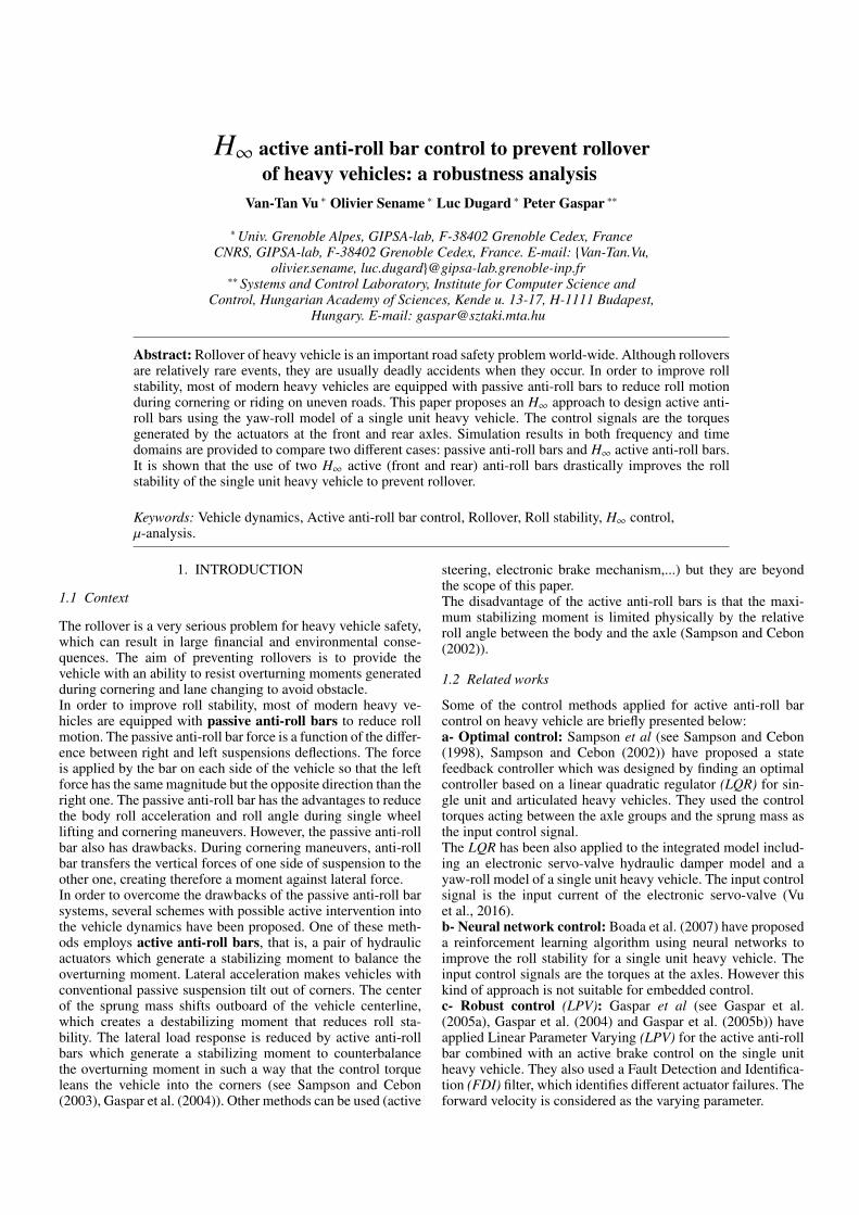
Fig 1 illustrates the combined yaw-roll dynamics of the vehiclemodelled by a three-body system, in which ms is the sprungmass, mu f the unsprung mass at the front including the frontwheels and axle, and mur the unsprung mass at the rear withthe rear wheels and axle. The parameters and variables of theyaw-roll model are shown in the table 1.In the vehicle modelling, the differential equations of motionof the yaw-roll dynamics of the single unit vehicle, i.e. thelateral dynamics, the yaw moment, the roll moment of thesprung mass, the roll moment of the front and the rear unsprungmasses, are formalized in the equations (1):
mv(β+ ψ)−mshφ = Fy f + Fyr
−Ixzφ+ Izzψ = Fy f l f −Fyrlr(Ixx + msh2)φ− Ixzψ = msghφ+ msvh(β+ ψ)−k f (φ−φt f )−b f (φ− φt f ) + MAR f + U f
−kr(φ−φtr)−br(φ− φtr) + MARr + Ur
−rFy f = mu f v(r−hu f )(β+ ψ) + mu f ghu f .φt f − kt fφt f
+k f (φ−φt f ) + b f (φ− φt f ) + MAR f + U f
−rFyr = murv(r−hur)(β+ ψ)−murghurφtr − ktrφtr
+kr(φ−φtr) + br(φ− φtr) + MARr + Ur
(1)
In (1) the lateral tire forces Fy;i in the direction of velocity at thewheel ground contact points are modelled by a linear stiffnessas: {
Fy f = µC fα f
Fyr = µCrαr(2)
Table 1. Parameters of the yaw-roll model (seeGaspar et al. (2004))
Symbols Description Value Unit
ms Sprung mass 12487 kgmu, f Unsprung mass on the front axle 706 kgmu,r Unsprung mass on the rear axle 1000 kgm The total vehicle mass 14193 kgv Forward velocity - Km
hvwi Components of the forward velocity - Km
hh Height of CG of sprung mass from roll axis 1.15 m
hu,i Height of CG of unsprung mass from ground 0.53 mr Height of roll axis from ground 0.83 may Lateral acceleration - m
s2
β Side-slip angle at center of mass - radψ Heading angle - radψ Yaw rate - rad
sα Side slip angle - radφ Sprung mass roll angle - radφt,i Unsprung mass roll angle - radδ f Steering angle - radui Control current - AC f Tire cornering stiffness on the front axle 582 kN
radCr Tire cornering stiffness on the rear axle 783 kN
radk f Suspension roll stiffness on the front axle 380 kNm
radkr Suspension roll stiffness on the rear axle 684 kNm
radb f Suspension roll damping on the front axle 100 kN
radbr Suspension roll damping on the rear axle 100 kN
radkt f Tire roll stiffness on the front axle 2060 kNm
radktr Tire roll stiffness on the rear axle 3337 kNm
radIxx Roll moment of inertia of sprung mass 24201 kgm2
Ixz Yaw-roll product of inertial of sprung mass 4200 kgm2
Izz Yaw moment of inertia of sprung mass 34917 kgm2
l f Length of the front axle from the CG 1.95 mlr Length of the rear axle from the CG 1.54 mlw Half of the vehicle width 0.93 mµ Road adhesion coefficient 1 -
with tire side slip angles:α f = −β+δ f −
l f ψ
v
αr = −β+lrψv
(3)
Let us now detail how the moment MAR f and MARr in (1) arecomputed. When the vertical displacements of the left and theright wheels differ, the passive anti-roll bar with a rotationalstiffness kAO creates an anti-roll moment, resulting in the anti-roll force FAU , see Figure 2, acting on the unsprung mass as:
FAUl = −FAUr = kAU (∆ZAr −∆ZAl) (4)
and the anti-roll force FAS acting on the sprung mass is:
FAS l = −FAS r = FAUltA
tB= kAS (∆ZAr −∆ZAl) (5)
where ∆ZAr,l are the displacements of the connection pointbetween the anti-roll bars and the wheels, tA is half the distanceof the two suspensions, tB is half the distance of the chassis,c is the length of the anti-roll bars’s arm, kAU and kAS are themodified rotational stiffness corresponding to the unsprung andsprung mass, respectively:
kAU = kAO1c2 and kAS = kAO
tA
tBc2 (6)
The moment of passive anti-roll bar impacts the unsprung andsprung masses at the front axle as follows:
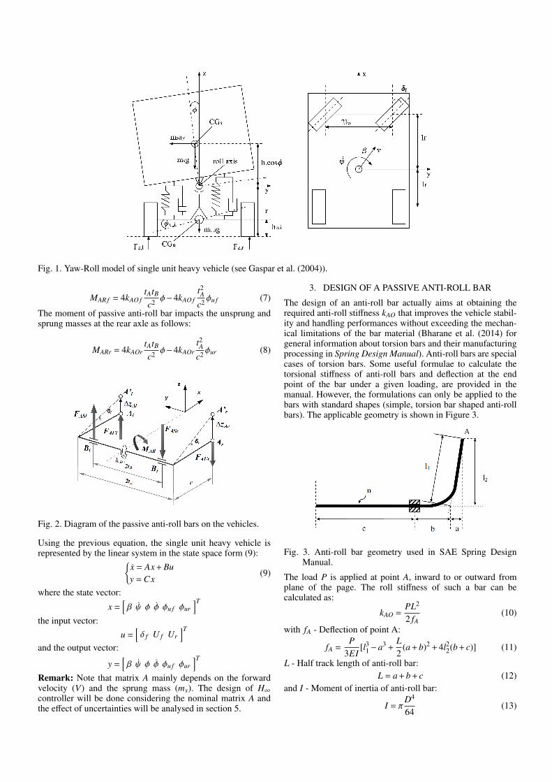
Fig. 1. Yaw-Roll model of single unit heavy vehicle (see Gaspar et al. (2004)).
MAR f = 4kAO ftAtB
c2 φ−4kAO ft2A
c2 φu f (7)
The moment of passive anti-roll bar impacts the unsprung andsprung masses at the rear axle as follows:
MARr = 4kAOrtAtB
c2 φ−4kAOrt2A
c2 φur (8)
Fig. 2. Diagram of the passive anti-roll bars on the vehicles.
Using the previous equation, the single unit heavy vehicle isrepresented by the linear system in the state space form (9):{
x = Ax + Buy = Cx
(9)
where the state vector:
x =[β ψ φ φ φu f φur
]Tthe input vector:
u =[δ f U f Ur
]Tand the output vector:
y =[β ψ φ φ φu f φur
]TRemark: Note that matrix A mainly depends on the forwardvelocity (V) and the sprung mass (ms). The design of H∞controller will be done considering the nominal matrix A andthe effect of uncertainties will be analysed in section 5.
3. DESIGN OF A PASSIVE ANTI-ROLL BAR
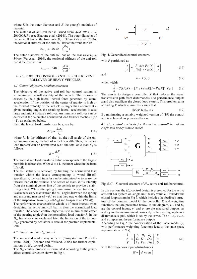
The design of an anti-roll bar actually aims at obtaining therequired anti-roll stiffness kAO that improves the vehicle stabil-ity and handling performances without exceeding the mechan-ical limitations of the bar material (Bharane et al. (2014) forgeneral information about torsion bars and their manufacturingprocessing in Spring Design Manual). Anti-roll bars are specialcases of torsion bars. Some useful formulae to calculate thetorsional stiffness of anti-roll bars and deflection at the endpoint of the bar under a given loading, are provided in themanual. However, the formulations can only be applied to thebars with standard shapes (simple, torsion bar shaped anti-rollbars). The applicable geometry is shown in Figure 3.
Fig. 3. Anti-roll bar geometry used in SAE Spring DesignManual.
The load P is applied at point A, inward to or outward fromplane of the page. The roll stiffness of such a bar can becalculated as:
kAO =PL2
2 fA(10)
with fA - Deflection of point A:
fA =P
3EI[l31−a3 +
L2
(a + b)2 + 4l22(b + c)] (11)
L - Half track length of anti-roll bar:L = a + b + c (12)
and I - Moment of inertia of anti-roll bar:
I = πD4
64(13)
where D is the outer diameter and E the young’s modulus ofmaterial.The material of anti-roll bar is issued from AISI 1065, E =206000MPa (see Bharane et al. (2014)). The outer diameter ofthe anti-roll bar on the front axle D f = 32mm (Vu et al., 2016),the torsional stiffness of the anti-roll bar at the front axle is:
kAO f = 10730 (Nmrad
)
The outer diameter of the anti-roll bar on the rear axle Dr =34mm (Vu et al., 2016), the torsional stiffness of the anti-rollbar at the rear axle is:
kAOr = 15480 (Nmrad
)
4. H∞ ROBUST CONTROL SYNTHESIS TO PREVENTROLLOVER OF HEAVY VEHICLES
4.1 Control objective, problem statement
The objective of the active anti-roll bar control system isto maximize the roll stability of the vehicle. The rollover iscaused by the high lateral inertial force generated by lateralacceleration. If the position of the center of gravity is high orthe forward velocity of the vehicle is larger than allowed at agiven steering angle, the resulting lateral acceleration is alsolarge and might initiate a rollover. An imminent rollover can bedetected if the calculated normalized load transfer reaches 1 (or−1), as explained below.First, the lateral load transfer can be given by:
∆Fz =kuφu
lw(14)
where ku is the stiffness of tire, φu the roll angle of the un-sprung mass and lw the half of vehicle’s width. Then, the lateralload transfer can be normalized w.r.t. the total axle load Fz asfollows:
R =∆Fz
Fz(15)
The normalized load transfer R value corresponds to the largestpossible load transfer. When R =±1, the inner wheel in the bendlifts off.The roll stability is achieved by limiting the normalized loadtransfer within the levels corresponding to wheel lift-off.Specifically, the load transfer can be minimized to increase theinward lean of the vehicle. The center of mass shifts laterallyfrom the nominal center line of the vehicle to provide a stabi-lizing effect. While attempting to minimize the load transfer, itis also necessary to constrain the roll angles between the sprungand unsprung masses (φ−φu) so that they stay within the limitsof the suspension travel ((7−8deg) see Gaspar et al. (2004)).The performance characteristic which is of most interest whendesigning the active anti-roll bar, is then the normalized loadtransfer. The chosen control objective is to minimize the effectof the steering angle δ on the normalized load transfer R, in theH∞ framework. As explained later, the limitation of the torquesU f ,r generated by actuators is crucial for practice implementa-tion.
4.2 Background on H∞ control
The interested reader may refer to (Skogestad and Postleth-waite, 2001), (Scherer and Weiland, 2005) for further expla-nations on H∞ control design.The H∞ control problem is formulated according to the gener-alized control structure shown in Fig 4.
Fig. 4. Generalized control structure.
with P partitioned as[zy
]=
[P11(s) P12(s)P21(s) P22(s)
] [du
](16)
andu = K(s).y (17)
which yieldszd
= Fl(P,K) := [P11 + P12K[I−P22K]−1P21] (18)
The aim is to design a controller K that reduces the signaltransmission path from disturbances d to performance outputsz and also stabilizes the closed-loop system. This problem aimsat finding K which minimizes γ such that
‖Fl(P,K)‖∞ < γ (19)By minimizing a suitably weighted version of (19) the controlaim is achieved, as presented below.
4.3 H∞ control synthesis for the active anti-roll bar of thesingle unit heavy vehicle model
Fig. 5. G−K control structure of H∞ active anti-roll bar control.
In this section, the H∞ control design is presented for the activeanti-roll bar system on single unit heavy vehicle. Consider theclosed-loop system in Fig 5, which includes the feedback struc-ture of the nominal model G, the controller K and weightingfunctions that are presented below. In the diagram, U f and Urare the control inputs, y1 and y2 are the measured outputs, n1and n2 are the measurement noises. δ f is the steering angle as adisturbance signal, which is set by the driver. The e1, e2, e3, e4and e5 represent the performance outputs.According to Fig 5 the concatenation of the linear model (9)with performance weighting functions lead to the state spacerepresentation of P(s): X
ZY
= A B1 B2
C1 D11 D12C2 D21 D22
X
WU
(20)
with the exogenous input (disturbance):
W =[
d n1 n2]
the control input:
U =[
U f Ur]T
where U f is the torque at the front axle, Ur is the torque at therear axle.the performance output vector:
Z =[
e1 e2 e3 e4 e5]T
the measured output vector:
Y =[
ay φ]T
and A, B1, B2, C1, D11, D12, C2, D21, D22 are model matricesof appropriate dimensions.In H∞ control the selection of the weighting functions is akey step that is to be handled using the knowledge of theengineers concerning the system behavior and characteristics.The weighting functions of Fig 5 are given here after.The input scaling weight Wd normalizes the steering angle tothe maximum expected command and is selected as follows:
Wd = π/180This value corresponds to a 10 steering angle command.The weighting functions Wn1 and Wn2 are selected as:
Wn1 = Wn2 = 0.01which accounts for small sensor noise models in the controldesign. The noise weights are chosen 0.01(m/s2) for the lateralacceleration and 0.01(0/sec) for the derivative of roll angleφ (see (Gaspar et al., 2004)). Other low pass filters could beselected.The weighting functions Wzi represent the performance outputs(Wz1, Wz2, Wz3, Wz4 and Wz5). The purpose of the weightingfunctions is to keep small the control inputs, normalized loadtransfers and the lateral acceleration over the desired frequencyrange. The weighting functions chosen for performance outputscan be considered as penalty functions, that is, weights shouldbe large in the frequency range where small signals are desiredand small where larger performance outputs can be tolerated.The weighting functions Wz1 and Wz2 are chosen as:
Wz1 = 1/1.5x105, Wz2 = 1/2x105
which correspond to the front and rear control torques gener-ated by active anti-roll bars.The weighting functions Wz3 and Wz4 are selected as:
Wz3 = Wz4 = 1which means that the maximal gain of the normalized loadtransfers can be 1 in the frequency domain for front and rearaxles.The weighting function Wz5 is selected as:
Wz5 =(s/2000 + 50)
(s/0.01 + 0.01)(21)
Here, the weighting function Wz5 corresponds to a design thatavoids the rollover situation with the bandwidth of the driverin frequency range up to more than 4rad/s. This weightingfunction will minimize directly the lateral acceleration whenit reaches the critical value to avoid the rollover.
4.4 Frequency domain analysis with nominal value
The limited bandwidth of the driver must be considered up to4rad/s to identify any resonances in the response that may beexcited by the driver (see Gaspar et al. (2004) and Sampson(2000)). Therefore, it is necessary to consider the behavior ofthe heavy vehicle in a wider frequency range. In this section, the
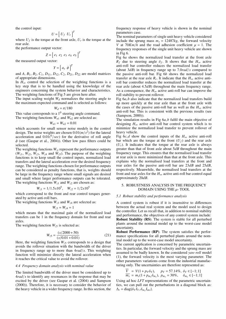
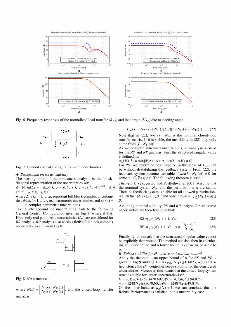
frequency response of heavy vehicle is shown in the nominalparameters case.The nominal parameters of single unit heavy vehicle consideredinclude the sprung mass ms = 12487kg, the forward velocityV at 70Km/h and the road adhesion coefficient µ = 1. Thefrequency responses of the single unit heavy vehicle are shownin Fig 6.Fig 6a shows the normalized load transfer at the front axleR f due to steering angle δ f . It shows that the H∞ activeanti-roll bar controller reduces the normalized load transfer(about 3dB) in frequency range up to 7.0rad/s compared tothe passive anti-roll bar. Fig 6b shows the normalized loadtransfer at the rear axle Rr. It indicate that the H∞ active anti-roll bar controller reduces the normalized load transfer at therear axle (about 4.5dB) throughout the main frequency range.As a consequence, the H∞ active anti-roll bar can improve theroll stability to prevent rollover.Fig 6a,b also indicate that the normalized load transfers buildup more quickly at the rear axle than at the front axle withthe cases of the passive anti-roll bar as well as the H∞ activeanti-roll bar. This is consistent with the previous results (see(Sampson, 2000)).The simulation results in Fig 6a,b fulfil the main objective ofdesigning H∞ active anti-roll bar control system which is tominimize the normalized load transfer to prevent rollover ofheavy vehicle.Fig 6c,d show the control inputs of the H∞ active anti-rollbar which are the torque at the front (U f ) and the rear axle(Ur). It indicates that the torque at the rear axle is alwaysgreater than that of front axle about 5dB throughout the mainfrequency range. This ensures that the normalised load transferat rear axle is more minimized than that at the front axle. Thisexplains why the normalised load transfers at the front andrear axles for the passive anti-roll bar are 23dB and 25dB,respectively. Meanwhile, the normalised load transfers at thefront and rear axles for the H∞ active anti-roll bar control equalapproximately 20dB.
5. ROBUSTNESS ANALYSIS IN THE FREQUENCYDOMAIN USING THE µ- TOOL
5.1 Robust stability and performance analysis
A control system is robust if it is insensitive to differencesbetween the actual real system and the model used to designthe controller. Let us recall that, in addition to nominal stabilityand performance, the objectives of any control system include:Robust Stability (RS). The system is stable for all perturbedplants around the nominal model up to the worst-case modeluncertainty.Robust Performance (RP). The system satisfies the perfor-mance specifications for all perturbed plants around the nom-inal model up to the worst-case model uncertainty.The current application is concerned by parametric uncertain-ties. In particular, the forward velocity and the sprung mass areassumed to be badly known. In the considered yaw-roll model(1), the forward velocity is the most varying parameter. Theother parameters variations come from the industrial manufac-turing only. The uncertainties are therefore represented as:
V = V(1 + pVδV ), pV = 57.14%, δV ∈ [−1;1]ms = ms(1 + pmsδms ), pms = 30%, δms ∈ [−1;1]
Using ad hoc LFT representations of the parametric uncertain-ties, we can pull out the perturbations in a diagonal block as:∆r = diag{δV IV , δms Ims}.
10−2
10−1
100
101
102
0
5
10
15
20
25
30
Mag
nitu
de (
dB)
Normalized load transfer on the front axle (Rf) due to steering angle
Frequency (rad/s)
H∞ Active Anti−roll bar, V= 70 Km/hPassive Anti−roll bar, V= 70 Km/h
10−2
10−1
100
101
102
−20
−10
0
10
20
30
40
Mag
nitu
de (
dB)
Normalized load transfer on the rear axle (Rr) due to steering angle
Frequency (rad/s)
H∞ Active Anti−roll bar, V= 70 Km/hPassive Anti−roll bar, V= 70 Km/h
10−2
10−1
100
101
102
70
80
90
100
110
Mag
nitu
de (
dB)
Torque on the front axle (Uf) due to steering angle
Frequency (rad/s)
Torque on the front axle (Uf), V= 70 Km/h
10−2
10−1
100
101
102
80
90
100
110
120
Mag
nitu
de (
dB)
Torque on the rear axle (Ur) due to steering angle
Frequency (rad/s)
Torque on the rear axle (Ur), V= 70 Km/h
a) b)
c) d)
Fig. 6. Frequency responses of the normalized load transfer (R f ,r) and the torque (U f ,r) due to steering angle.
Fig. 7. General control configuration with uncertainties.
A- Background on robust stabilityThe starting point of the robustness analysis is the block-diagonal representation of the uncertainties set:∆ = {diag{∆1, · · · ,∆q, δ1Ir1 , · · · , δrIrr , ε1Ic1 , · · · , εcIcc } ∈C
k×k, ∆i ∈
Cki×ki , δi ∈ R, εi ∈ C}.where ∆i(s), i = 1, . . . ,q, represent full block complex uncertain-ties, δi(s), i = 1, . . . ,r, real parametric uncertainties, and εi(s), i =1, . . . ,c, complex parametric uncertainties.Taking into account the uncertainties leads to the followingGeneral Control Configuration given in Fig 7, where ∆ ∈ ∆.Here, only real parametric uncertainties (∆r) are considered forRS analysis. RP analysis also needs a fictive full block complexuncertainty, as shown in Fig 8.
Fig. 8. N∆ structure.
where N(s) =
[N11(s) N12(s)N21(s) N22(s)
], and the closed-loop transfer
matrix is:
Tew(s) = N22(s) + N21(s)∆(s)(I−N11(s))−1N12(s) (22)
Note that in (22), N22(s) = New is the nominal closed-looptransfer matrix. If it is stable, the unstability in (22) may onlycome from (I−N11(s))−1.As we consider structured uncertainties, a µ-analysis is usedfor the RS and RP analysis. First the structured singular valueis defined as:µ∆(M)−1 := min{σ(∆) : ∆ ∈ ∆, det(I−∆M) , 0}.For RS , we determine how large ∆ (in the sense of H∞) canbe without destabilizing the feedback system. From (22), thefeedback system becomes unstable if det(I − N11(s)) = 0 forsome s ∈ C,<(s) ≥ 0. The following theorem is used.Theorem 1. (Skogestad and Postlethwaite, 2001) Assume thatthe nominal system New and the perturbations ∆ are stable.Then the feedback system is stable for all allowed perturbations∆ such that ||∆(s)| |∞ < 1/β if and only if ∀ω ∈R, µ∆ (N11( jω))≤β.
Assuming nominal stability, RS and RP analysis for structureduncertainties are therefore such that:
RS⇔ µ∆r (N11) < 1, ∀ω (23)
RP⇔ µ∆(N) < 1, ∀ω, ∆ =
[∆ f 00 ∆r
](24)
Finally, let us remark that the structured singular value cannotbe explicitly determined. The method consists then in calculat-ing an upper bound and a lower bound, as close as possible toµ.B- Robust stability for H∞ active anti-roll bar controlApply the theorem 1, an upper bound of µ for RS and RP isgiven in Fig 9 and Fig 10. As µ∆r (N11) ≤ 0.6023, RS is satis-fied. Hence the H∞ controller keeps stability for the considereduncertainties. Moreover, this means that the closed-loop systemremains stable for larger uncertainties,i.e.:V = 70Km/h± (57.14/0.6023)% = 70Km/h±94.87%ms = 12487kg± (30/0.6023)% = 12487kg±49.81%On the other hand, as µ∆(N) < 1, we can conclude that theRobust Performance is satisfied in this uncertainty case.
10−2
10−1
100
101
102
0
5
10
15
20
25
30
Mag
nitu
de (
dB)
Normalized load transfer on the front axle (Rf) due to steering angle
Frequency (rad/s)
H∞ Active Anti−roll barPassive Anti−roll bar
10−2
10−1
100
101
102
−20
−10
0
10
20
30
40
Mag
nitu
de (
dB)
Normalized load transfer on the rear axle (Rr) due to steering angle
Frequency (rad/s)
H∞ Active Anti−roll barPassive Anti−roll bar
10−2
10−1
100
101
102
60
70
80
90
100
110
120
Mag
nitu
de (
dB)
Torque on the front axle (Uf) due to steering angle
Frequency (rad/s)
Torque on the front axle (Uf)
10−2
10−1
100
101
102
80
90
100
110
120
Mag
nitu
de (
dB)
Torque on the rear axle (Ur) due to steering angle
Frequency (rad/s)
Torque on the rear axle (Ur)
Increase V=50−110 Km/h
Increase V=50−110 Km/h
Increase V=50−110 Km/h
Increase V=50−110 Km/h
a) b)
c) d)
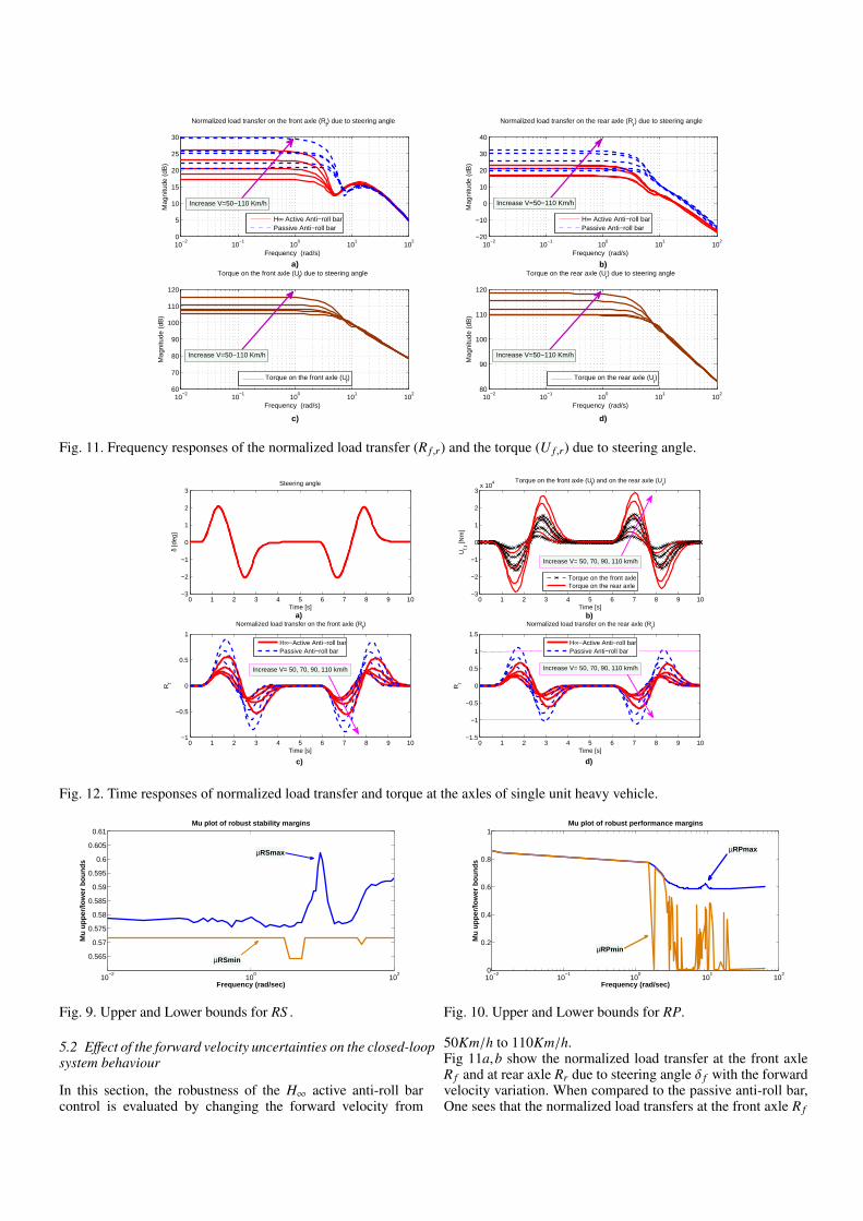
Fig. 11. Frequency responses of the normalized load transfer (R f ,r) and the torque (U f ,r) due to steering angle.
0 1 2 3 4 5 6 7 8 9 10−3
−2
−1
0
1
2
3Steering angle
δ [d
eg]
Time [s]0 1 2 3 4 5 6 7 8 9 10
−3
−2
−1
0
1
2
3x 10
4 Torque on the front axle (Uf) and on the rear axle (U
r)
Uf,r
[Nm
]
Time [s]
0 1 2 3 4 5 6 7 8 9 10−1
−0.5
0
0.5
1
Normalized load transfer on the front axle (Rf)
Rf
Time [s]
0 1 2 3 4 5 6 7 8 9 10−1.5
−1
−0.5
0
0.5
1
1.5
Normalized load transfer on the rear axle (Rr)
Rr
Time [s]
Torque on the front axleTorque on the rear axle
H∞−Active Anti−roll barPassive Anti−roll bar
H∞−Active Anti−roll barPassive Anti−roll bar
Increase V= 50, 70, 90, 110 km/h Increase V= 50, 70, 90, 110 km/h
Increase V= 50, 70, 90, 110 km/h
b)
c) d)
a)
Fig. 12. Time responses of normalized load transfer and torque at the axles of single unit heavy vehicle.
10−2
100
102
0.565
0.57
0.575
0.58
0.585
0.59
0.595
0.6
0.605
0.61
Frequency (rad/sec)
Mu
up
per
/low
er b
ou
nd
s
Mu plot of robust stability margins
µRSmax
µRSmin
Fig. 9. Upper and Lower bounds for RS .
5.2 Effect of the forward velocity uncertainties on the closed-loopsystem behaviour
In this section, the robustness of the H∞ active anti-roll barcontrol is evaluated by changing the forward velocity from
10−2
10−1
100
101
102
0
0.2
0.4
0.6
0.8
1
Frequency (rad/sec)
Mu
up
per
/low
er b
ou
nd
s
Mu plot of robust performance margins
µRPmin
µRPmax
Fig. 10. Upper and Lower bounds for RP.
50Km/h to 110Km/h.Fig 11a,b show the normalized load transfer at the front axleR f and at rear axle Rr due to steering angle δ f with the forwardvelocity variation. When compared to the passive anti-roll bar,One sees that the normalized load transfers at the front axle R f
in case of the H∞ active anti-roll bar control have been reducedin frequency range up to 7.0rad/s. Meanwhile the normalizedload transfers at the rear axle Rr have been reduced throughoutthe main frequency range. The reduction of the normalizedload transfer at the front and at the rear axles in desired fre-quency range improves then the roll stability which preventsthe rollover of the single unit heavy vehicle.Fig 11c,d show the control inputs (U f , Ur) of the H∞ activeanti-roll bar at two axle. The torque at the rear axle is alwaysgreater than that of front axle throughout the main of the fre-quency range when the forward velocity varies from 50Km/hto 110Km/h.From the simulation results above, we can claim that the H∞active anti-roll bar control is robust w.r.t. the forward velocityvariation.
6. SIMULATIONS IN TIME DOMAIN
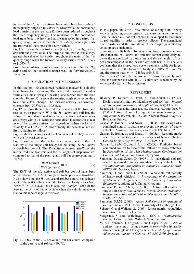
In this section, the considered vehicle maneuver is a doublelane change for overtaking. The lane used to overtake anothervehicle is almost always a passing lane further from the roadshoulder. Figure 12a shows the steering angle δ correspondingto a double lane change. The forward velocity is consideredconstant from 50Km/h to 110Km/h.Fig 12c,d show the normalized load transfers at the front andrear axles, respectively. With the H∞ active anti-roll bar, thevalues of normalized load transfer at the front and rear axlesare always within ±1, while the normalized load transfer at rearaxle of the passive anti-roll bar exceeds ±1 when the forwardvelocity V = 110Km/h. At this velocity, the wheels of vehiclelift on, leading to rollover.Fig 12b shows the torques at front and rear axles. They increasewith the forward velocity.Fig 13 summarizes the performance assessment of the rollstability of the single unit heavy vehicle using the H∞ activeanti-roll bar control. The Root Mean Squares (RMS) of thenormalized load transfers and the roll angles of suspension arecompared to that of the passive anti-roll bar (corresponding to100%).
RMS (active)RMS (passive)
100% (25)
The RMS of the H∞ active anti-roll bar control have beenreduced from 15% to 50% compared to the passive anti-roll bar.It also shows that the H∞ active anti-roll bar control has reduceda lot of the RMS values when the forward velocity varies from70Km/h to 100Km/h. This is also the ”danger” zone of theforward velocity of heavy vehicle when the vehicle maneuveris a double lane change to overtake.
1 2 3 40
20
40
60
80
100
%
50 Km/h70 Km/h90 Km/h110 Km/h
Rf φ−φ
uf φ−φur
Rr
Fig. 13. RMS of the H∞ active anti-roll bar control comparedto the passive anti-roll bar (100%).
7. CONCLUSION
In this paper, the Yaw - Roll model of a single unit heavyvehicle including active anti-roll bar systems at two axles isused. A linear H∞ control scheme is developed to maximizeits roll stability in order to prevent rollover. The normalizedload transfers and the limitations of the torque generated byactuators are considered.Simulation results both in frequency and time domains demon-strate that the H∞ active anti-roll bar control completely re-duces the normalized load transfers and the roll angles of sus-pension compared to the passive anti-roll bar. A µ- analysisconfirms that the closed-loop system remains stable for largeruncertainties with the forward velocity V = 70Km/h± 94.87%and the sprung mass ms = 12487kg±49.81%.Even if a LTI controller seems to performs reasonably wellhere, the comparison with an LPV controller (scheduled by thevehicle velocity) will be of interest.
REFERENCES
Bharane, P., Tanpure, K., Patil, A., and Kerkal, G. (2014).Design, analysis and optimization of anti-roll bar. Journalof Engineering Research and Applications, 4(9), 137–140.
Boada, M., Boada, B., Quesada, A., Gaucha, A., and Daz, V.(2007). Active roll control using reinforcement learning for asingle unit heavy vehicle. In 12th IFToMM World Congress.Besancon, France.
Gaspar, P., Bokor, J., and Szaszi, I. (2004). The design of acombined control structure to prevent the rollver of heavyvehicles. European Journal of Control, 10(2), 148–162.
Gaspar, P., Bokor, J., and Szaszi, I. (2005a). Reconfigurablecontrol structure to prevent the rollover of heavy vehicles.Control Engineering Practice, 13(6), 699–711.
Gaspar, P., Szabo, Z., and Bokor, J. (2005b). Prediction basedcombined control to prevent the rollover of heavy vehicles.In Proceedings of the 13th Mediterranean Conference onControl and Automation. Limassol, Cyprus.
Sampson, D. and Cebon, D. (1998). An investigation of rollcontrol system design for articulated heavy vehicles. In4th International symposium on Advanced Vehicle Control,AVEC1998. Nagoya, Japan.
Sampson, D. and Cebon, D. (2002). Achievable roll stabilityof heavy road vehicles. In Proceedings of the Institutionof Mechanical Engineers, Part D: Journal of AutomobileEngineering, volume 217. United Kingdom.
Sampson, D. and Cebon, D. (2003). Active roll control ofsingle unit heavy road vehicles. Vehicle System Dynamics:International Journal of Vehicle Mechanics and Mobility,40(4), 229–270.
Sampson, D.J.M. (2000). Active Roll Control of ArticulatedHeavy Vehicles. Ph.D. thesis, University of Cambridge, UK.
Scherer, C. and Weiland, S. (2005). Linear matrix inequalitiesin control. University Lecture.
Skogestad, S. and Postlethwaite, I. (2001). MultivariableFeedback Control. John Wiley & Sons, 2 edition.
Vu, V.T., Sename, O., Dugard, L., and Gaspar, P. (2016). Activeanti-roll bar control using electronic servo-valve hydraulicdamper on single unit heavy vehicle. In IFAC Symposium onAdvances in Automotive Control - 8th AAC 2016. Sweden.