Embed Size (px)
Citation preview
H-3551T
Owners manualV3.0
D46 0814
GAS PURGE BUBBLER
This user manual is a guide for the H-3551T. For more information, updated manuals, brochures, technical notes, and supporting software on the H-3551T, please refer to waterlog.com/3551 or contact your sales representative.
For additional assistance, please contact us at +1.435.753.2212 or [email protected]
CONTENTS & WARRANTY
waterlOG® warranty..........................................................1Chapter 1: Introduction.......................................................2
3Chapter 2: Getting started.................................................4
5Chapter 3: Installation........................................................ 6
778
Chapter 4: setup & Operation........................................101111111314
Chapter 5: maintenance & Troubleshooting................1517
Chapter 6: sDI-12 Command & response Protocol...181920222223232425
25-28Chapter 7: appendix..........................................................29
Bubbler Features................................................................. What’s in the Box.................................................................
Product Description............................................................Orifice & Sensor Connections...........................................Recommended Field Installation Procedures.................
Maintenance Pressure Pump Procedures.......................Purge Pump Failure...........................................................Operation with H-350XL...................................................Stand-alone Operation.....................................................Manual Purge.....................................................................
Bubble Test.........................................................................
Command Summary.........................................................Measure Command..........................................................Concurrent Measure Command.....................................Send Data Command.......................................................Send Acknowledgement Command..............................Initiate Verify Command...................................................Send Identification Command........................................Change Sensor Address Command..............................Extended Commands.................................................
1
Contents & Warranty
“WATERLOG™ PRODUCTS MANUFACTURED BY YELLOW SPRINGS INSTRUMENTS CO., INC. are warranted by Yellow Springs Instruments Co., Inc. (“YSI”) to be free from defects in materials and workmanship under normal use and service for twelve (12) months from date of shipment unless otherwise specified in the corresponding YSI pricelist or product manual.
WaterLOG™ products not manufactured, but that are re-sold by YSI, are warranted only to the limits extended by the original manufacturer. Batteries, desiccant, and other consumables have no warranty. YSI’s obligation under this warranty is limited to repairing or replacing (YSI’s option) defective products,which shall be the sole and exclusive remedy under this warranty.
The customer shall assume all costs of removing, reinstalling, and shipping defective products to YSI. YSI will return such products by surface carrier prepaid within the continental United States of America. To all other locations, YSI will return such products best way CIP (Port of Entry) INCOTERM® 2010, prepaid. This warranty shall not apply to any products which have been subjected to modification, misuse, neglect, improper service, accidents of nature, or shipping damage. This warranty is in lieu of all other warranties, expressed or implied. The warranty for installation services performed by YSI such as programming to customer specifications, electrical connections to products manufactured by YSI, and product specific training, is part of YSI’s product warranty. YSI EXPRESSLY DISCLAIMS AND EXCLUDES ANY IMPLIED WARRANTIES OF MERCHANTABILITY OR FITNESS FOR A PARTICULAR PURPOSE. YSI is not liable for any special, indirect, incidental, and/or consequential damages.”
A complete TERMS AND CONDITIONS OF SALE can be viewed at:http://www.ysi.com/terms-and-conditions.php
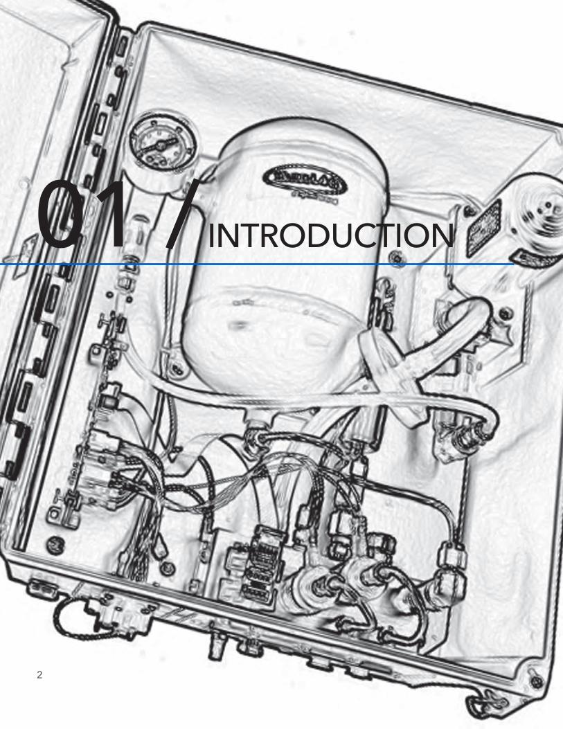
INTRODUCTION01 /
2
Introduction
3
The WaterLOG® H-3551T is a self-contained “smart” gas purge system which produces a precision, constant mass flow of gas. Together with a pressure measurement device, it is used to measure fluid levels in applications such as surface water (streams and lakes, etc.), ground water and tanks.
A sophisticated system of sensors and valves regulate the bubble rate and purge pressure. A battery operated compressor and an internal microprocessor controller determines how much pressure is needed in the tank based on the current head pressure, to produce a constant bubble rate. Hence, the term “smart”. The micro controller also compensates for the effects of gas density change with temperature to maintain a constant flow through the restriction. This portion of the H-3551T replaces the sight feed flow controller and pressure regulator (Conflow system) used in previous systems.
The bubbler also provides a purge feature which temporarily pumps up the tank to a high pressure and opens a valve to apply high pressure to the orifice line. This feature is designed to remove any sediment that may have collected in or around the outlet of the orifice line.
The H-3551T is used primarily with the WaterLOG® H-350XL data logger, which performs several different functions in the system. First, it is the precision pressure messurement source for measuring the fluid level. This function replaces the manometer in previous systems. Second, it is the terminal through which the H-3551T is configured. Third, it can be the data recorder for the system, thus removing the need for an external data recorder.
Key Features:
• Provides a continuous gas flow• Battery operated• Microprocessor controlled• One-piece manifold eliminates many potential sources of leaks• Pressure gauge provides a visual indication of the tank pressure• Hydrophobic intake membrane protects compressor• All components are easily accessible for inspection and maintenance• Compressor does not have a “diaphragm”• Provides an internal pressure relief valve• Compressor is designed and rated for cold temperature operation

GETTING STARTED02 /
4
Getting Started
5
Before installation, setup and operation of the H-3551T in the field, read through this section for a general overview of what you have and how to use it.
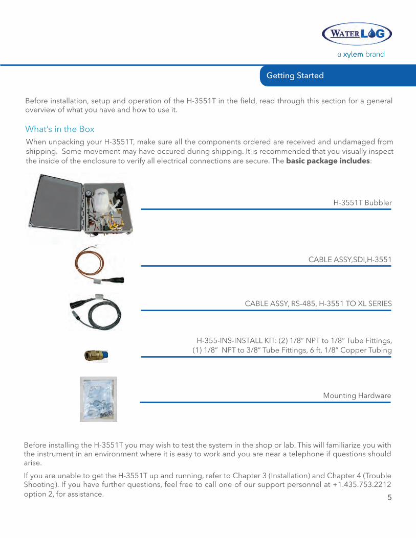
When unpacking your H-3551T, make sure all the components ordered are received and undamaged from shipping. Some movement may have occured during shipping. It is recommended that you visually inspect the inside of the enclosure to verify all electrical connections are secure. The basic package includes:
What’s in the Box
H-3551T Bubbler
CABLE ASSY,SDI,H-3551
CABLE ASSY, RS-485, H-3551 TO XL SERIES
H-355-INS-INSTALL KIT: (2) 1/8” NPT to 1/8” Tube Fittings, (1) 1/8” NPT to 3/8” Tube Fittings, 6 ft. 1/8” Copper Tubing
Before installing the H-3551T you may wish to test the system in the shop or lab. This will familiarize you with the instrument in an environment where it is easy to work and you are near a telephone if questions should arise.
If you are unable to get the H-3551T up and running, refer to Chapter 3 (Installation) and Chapter 4 (Trouble Shooting). If you have further questions, feel free to call one of our support personnel at +1.435.753.2212 option 2, for assistance.
Mounting Hardware
6
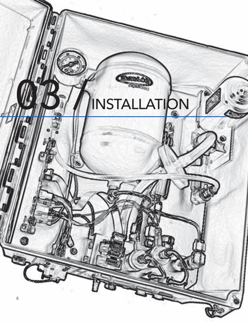
INSTALLATION03 /
Installation
7
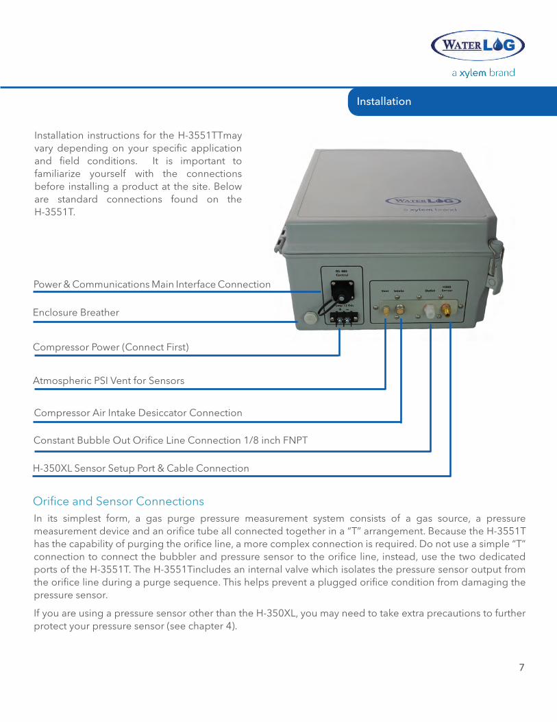
Installation instructions for the H-3551TTmay vary depending on your specific application and field conditions. It is important to familiarize yourself with the connections before installing a product at the site. Below are standard connections found on the H-3551T.
Atmospheric PSI Vent for Sensors
H-350XL Sensor Setup Port & Cable Connection
Compressor Air Intake Desiccator Connection
Constant Bubble Out Orifice Line Connection 1/8 inch FNPT
Enclosure Breather
Compressor Power (Connect First)
Power & Communications Main Interface Connection
In its simplest form, a gas purge pressure measurement system consists of a gas source, a pressure measurement device and an orifice tube all connected together in a “T” arrangement. Because the H-3551T has the capability of purging the orifice line, a more complex connection is required. Do not use a simple “T” connection to connect the bubbler and pressure sensor to the orifice line, instead, use the two dedicated ports of the H-3551T. The H-3551Tincludes an internal valve which isolates the pressure sensor output from the orifice line during a purge sequence. This helps prevent a plugged orifice condition from damaging the pressure sensor.
If you are using a pressure sensor other than the H-350XL, you may need to take extra precautions to further protect your pressure sensor (see chapter 4).
Orifice and Sensor Connections
INSTALLATION
8
1. The H-3551Tmust be wall mounted in the vertical position, with the manifold down. Mounting feet are provided. A vertical mount helps ensure moisture will not accumulate in the internal pressure tank.
2. Connect the pressure line between the H-3551T and your pressure measurement device. This can be done using the H-3551T Install kit. This kit is designed for use with the H-350XL. If your measurement device has different connections, you will need to provide the appropriate fittings. You will need a 1/8” NPT male tubing fitting for the sensor output. It is recommended that you use the 1/8” copper tubing supplied in the install kit. The proper ferrules must be used to insure there are no leaks.
3. The H-3551T requires two separate power sources. First is the compressor 12V which powers the compressor and control valves. This supply is typically made with heavy gauge wire to the gauge station 12V battery. Second is the 12V which powers the control module. This source is supplied from the pressure measurement sensor through the interface cable (provided), and into the control connector. It is best to connect the compressor power first, then the control power second. If a pumping sequence fails, the controller suspends pumping for a while to allow the battery to recharge. By connecting the pump power first, the controller will not prematurely detect a dead battery and suspend pumping.
4. Generally, an external desiccator is required to dry the intake air. The desiccator prevents accumulation of moisture in the tank, restriction and orifice line. Connect the output of the desiccator to the port marked “intake”. Desiccators which employ “indicating” silica gel have the advantage of visually showing the status of the desiccant. As the gel becomes saturated with moisture, the gel turns blue. See Appendix-B for further information and the specification for a recommended desiccator.
Recommended Field Installation Procedures
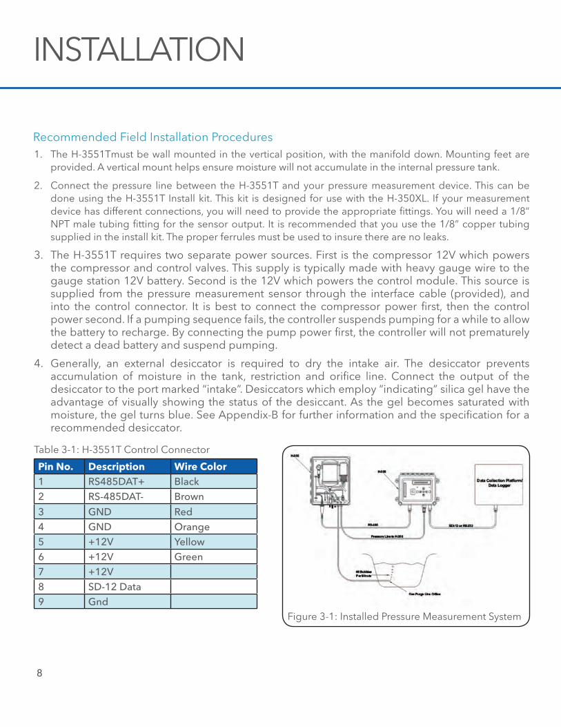
Pin no. Description wire Color1 RS485DAT+ Black2 RS-485DAT- Brown
3 GND Red4 GND Orange5 +12V Yellow6 +12V Green7 +12V8 SD-12 Data9 Gnd
Table 3-1: H-3551T Control Connector
Figure 3-1: Installed Pressure Measurement System
Installation
9
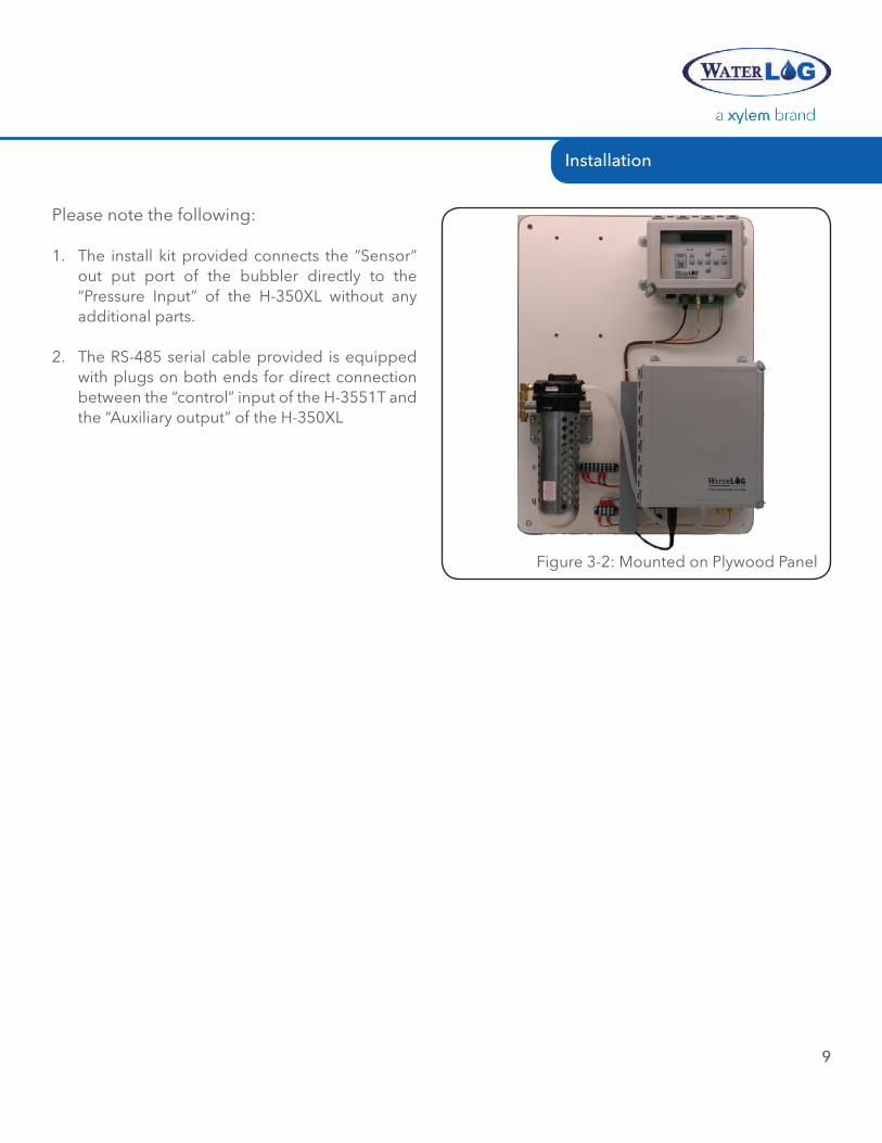
Figure 3-2: Mounted on Plywood Panel
Please note the following:
1. The install kit provided connects the “Sensor” out put port of the bubbler directly to the “Pressure Input” of the H-350XL without any additional parts.
2. The RS-485 serial cable provided is equipped with plugs on both ends for direct connection between the “control” input of the H-3551T and the “Auxiliary output” of the H-350XL
OPERATION04 /
10
11
Operation
During normal operation, if the tank pressure becomes too low the micro controller makes several tests before turning the compressor on:
1. If the compressor power input (terminal strip) is below 10.0 volts, the compressor will not turn on. This is to prevent further discharge of an already stressed battery.
2. The compressor will not turned on if a purge sequence within the previous elapsed 1-hour failed. This allows the battery charger to charge the battery without the compressor draining the battery as fast as it is charged. Once the compressor is turned on, the battery voltage is no longer monitored by the microcontroller.
Maintenance Pressure Pump FailureIf the compressor runs longer than 60 seconds while pumping the tank to the pressure needed for the desired bubble rate, the micro controller turns off the compressor and disables further pumping for 30-seconds.
Purge Pump FailureWhen a purge sequence is initiated, the compressor is activated to pump the tank to the specified purge pressure. If the compressor runs longer than 300 seconds while pumping the tank to the proper pressure, the micro controller turns off the compressor and disables all further pumping for 1-hour.
While servicing the system, these battery protection features can be inadvertently activated if the 12V pump power (via the terminal strip) is disconnected or fails while the compressor is running. You can recover from these lockout conditions by momentarily disconnecting the RS-485 control connector to reset the micro controller
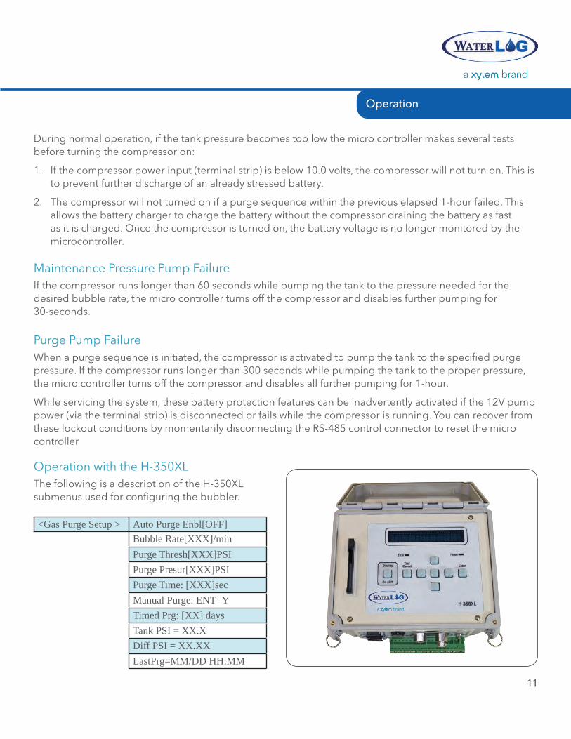
Operation with the H-350XLThe following is a description of the H-350XL submenus used for configuring the bubbler.
<Gas Purge Setup > Auto Purge Enbl[OFF]Bubble Rate[XXX]/minPurge Thresh[XXX]PSIPurge Presur[XXX]PSIPurge Time: [XXX]secManual Purge: ENT=YTimed Prg: [XX] daysTank PSI = XX.XDiff PSI = XX.XXLastPrg=MM/DD HH:MM
OPERATION
12
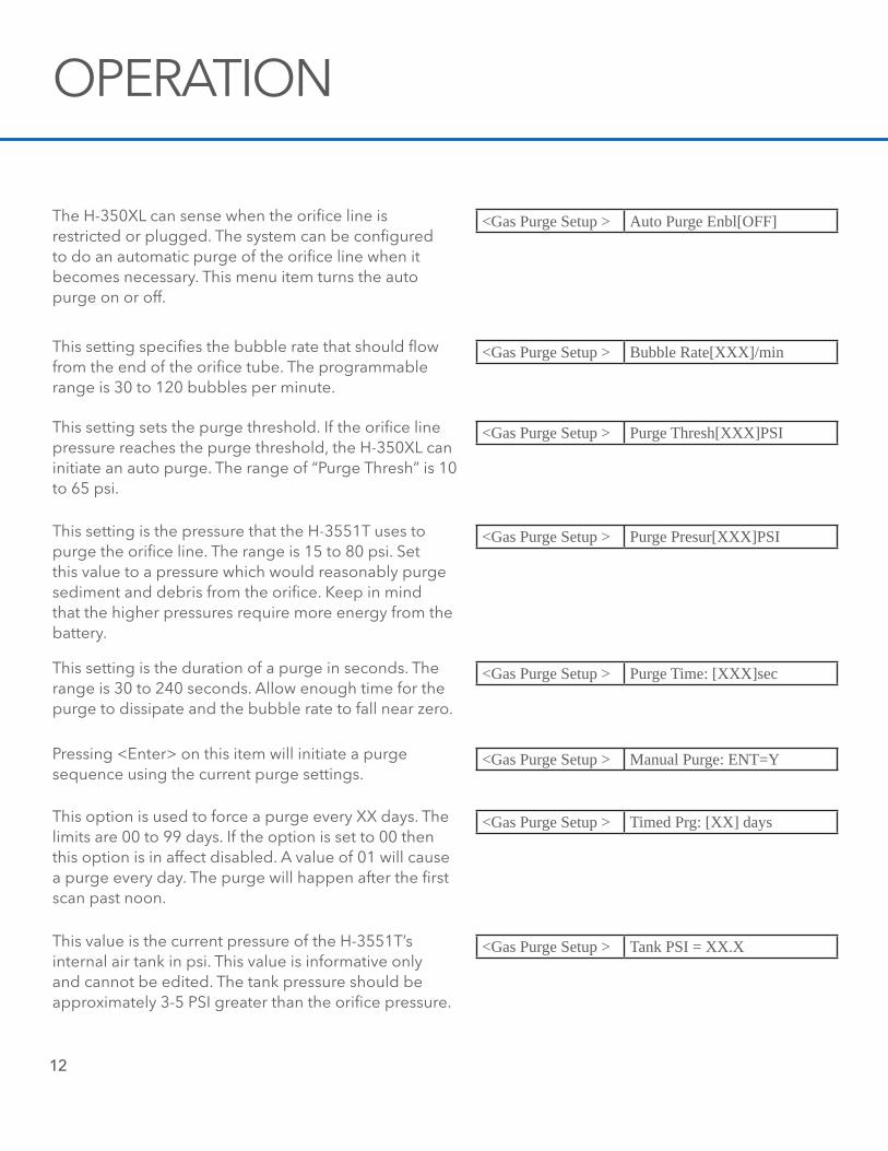
The H-350XL can sense when the orifice line is restricted or plugged. The system can be configured to do an automatic purge of the orifice line when it becomes necessary. This menu item turns the auto purge on or off.
<Gas Purge Setup > Auto Purge Enbl[OFF]
<Gas Purge Setup > Bubble Rate[XXX]/minThis setting specifies the bubble rate that should flow from the end of the orifice tube. The programmable range is 30 to 120 bubbles per minute.
<Gas Purge Setup > Purge Thresh[XXX]PSIThis setting sets the purge threshold. If the orifice line pressure reaches the purge threshold, the H-350XL can initiate an auto purge. The range of “Purge Thresh” is 10 to 65 psi.
<Gas Purge Setup > Purge Presur[XXX]PSIThis setting is the pressure that the H-3551T uses to purge the orifice line. The range is 15 to 80 psi. Set this value to a pressure which would reasonably purge sediment and debris from the orifice. Keep in mind that the higher pressures require more energy from the battery.
<Gas Purge Setup > Purge Time: [XXX]secThis setting is the duration of a purge in seconds. The range is 30 to 240 seconds. Allow enough time for the purge to dissipate and the bubble rate to fall near zero.
<Gas Purge Setup > Manual Purge: ENT=YPressing <Enter> on this item will initiate a purge sequence using the current purge settings.
<Gas Purge Setup > Timed Prg: [XX] daysThis option is used to force a purge every XX days. The limits are 00 to 99 days. If the option is set to 00 then this option is in affect disabled. A value of 01 will cause a purge every day. The purge will happen after the first scan past noon.
<Gas Purge Setup > Tank PSI = XX.XThis value is the current pressure of the H-3551T’s internal air tank in psi. This value is informative only and cannot be edited. The tank pressure should be approximately 3-5 PSI greater than the orifice pressure.
Operation
13
<Gas Purge Setup > Diff PSI = XX.XXThis value is the difference between the tank pressure and the pressure on the orifice line in psi. Like tank psi, this value cannot be edited. This value is directly proportional to the bubble rate and should be approximately 3-5 PSI.
<Gas Purge Setup > Last Prg=MM/DD HH:MMThis display shows the month, day any hour when the last purge sequence was made.
If the auto-purge feature of the H-350XL is enabled, the H-350XL is responsible for initiating purges. Whenever the H-350XL makes a measurement, it compares the pressure data with the “Purge Threshold” value. If the pressure is greater than the Purge Threshold, the H-350XL commands the bubbler to initiate a purge sequence. During the purge, the H-350XL energizes its internal auto-zero valve to isolate the H-350XL's precision sensor from the purge pressure. At the completion of the purge, the H-350XL keeps its auto-zero valve energized for an additional 2.0 seconds. This is done to prevent damage to the H-350XL's precision sensor in case the orifice is plugged and the orifice line momentarily holds the full purge pressure. A pressure relief valve in the bubbler vents the over pressure to atmosphere during the 2 second delay.
After completion of a purge sequence, the H-350XL makes another pressure measurement. If the pressure is still greater than the Purge Threshold value, the H-350XL knows the purge failed. It then activates a timer which disables further purges for the next 24 hours. This is done to prevent a plugged orifice form causing continuous purges which would quickly drain the battery.
Stand-Alone OperationThe H-3551T gas purge system can be used “stand-alone” with pressure measurement devices other than the H-350XL. You do lose some flexibility in that you cannot edit the bubbler settings in the field and the purge feature cannot be coordinated with a pressure measurement such that pressure measurements are not made during a purge.
When operating stand-alone, the factory preset values are:
Bubble Rate: 60 Bub/min Pressure to Purge With: 40 PSI Pressure to Initiate a Purge: 20 PSI Purge Time: 45 sec
These settings can also be monitored or edited via the SDI-12 port built into the H-3551T The H-3551T functions as a SDI-12 “sensor”. When connected to a SDI-12 host such as a data logger or H-4191 RS-232 side-kick interface you can issue extended SDI-12 commands to read or write these settings. If the data logger issues and “aM!” command, the H-3551T initiates a purge sequence. See Chapter 5 for further details.
If needed, these settings can be configured at the factory. The factory must be notified of desired settings prior to shipment.
warnInG: THERE IS A DISTINCT POSSIBILITY OF DESTROYING YOUR PRESSURE SENSOR. THIS CAN BE AVOIDED BY INSTALLING AN ISOLATION VALVE BETWEEN THE H-3551T AND YOUR SENSOR.
If a purge does not clear a plugged orifice line, the purge pressure will be applied to the sensor output of the H-3551T. The H-350XL has an internal valve which protects its precision pressure transducer from a failed purge. When operating the H-3551T with a sensor other than the H-350XL, the purge pressure could be applied to your sensor before the H-3551T's internal pressure relief valve can pop. It is your responsibility to verify that your sensor can handle the purge pressure, or install an isolation valve between the H-3551T and your sensor. The valve must be closed prior to a purge and remain closed until the purge is completed, or until the tank pressure falls below your sensor’s maximum pressure rating.
OPERATION
14
Manual PurgeThe H-3551T has an internal button which allows a manual purge to be initiated. This feature allows you to clear a plugged orifice or verify the orifice is clear. The Purge button is located inside the H-3551T enclosure, on the top corner of the control module. Pressing this for one to two seconds initiates a purge sequence. The compressor will be turned on and the tank pressure raised to the “Purge Pressure”. During this time, the bubble rate will rise proportionally with the pressure. Next, the compressor is turned off and the purge valve is actuated to dump the tank pressure directly to the orifice line. While the purge valve is actuated the pressure sensor output is blocked by a valve to prevent the purge pressure from damaging the pressure measurement system. During the purge, the orifice should produce vigorous bubbling with the bubble rate falling eventually to zero. After a delay equal to the “Purge Delay”, the purge valve is closed and the compressor is again turned on to restore the bubble rate to its normal value.
nOTe: When the button is pressed, if the tank pressure is already higher than the “Purge Pressure” the purge sequence will not be initiated.
15
MAINTENANCE &TROUBLE SHOOTING05 /
16
MAINTENANCE & TROUBLE SHOOTING
Sustained operation of the H-3551Tis almost maintenance-free. Because the compressor only runs for a few seconds every hour, it will last for many years. The H-3551Tincludes safety provisions that will not allow the compressor to run continuously for long periods of time. This protects the pump and other components in case of a plugged orifice or other malfunction.
Periodically check your gauge station battery to ensure it is in good condition for pumping together with any other equipment that you have installed in the gauge station.
From time to time check the inlet line filter (located between the manifold and the suction side of the pump) for any blockage or restriction. If blockage or restriction is present, the filter must be replaced.
All fittings must be secure. At 60 bubbles/minute, even a tiny leak will allow the entire gas flow to escape.
Maintenance
It is unlikely that this manual will ever contain trouble shooting tips to cover every problem that will be encountered. Feedback from customers is very valuable and greatly aids in the quest for constant product enhancement. Please feel free to call the factory for technical assistance and also with solutions you have found to past problems.
The following list of problems and possible solutions.
H-350 reports “H-355 NOT RESPONDING”!
• Verify the power connections to the H-3551T. Reinitialize the internal controller by momentarily unplugging the RS-485 control cable connector.
• Check all connections including Power, Gnd and the RS-485 communication connector. +12V power must be supplied via both the compressor power terminals and the RS-485 connector (from the data logger)
Intermittent Operation
• Check your power and ground connections. Moisture over time can oxidize and corrode the battery terminals, connectors and pins.
• Measure the power supply/battery voltage at the input terminal strip while the pump is running.
• The H-3551T has several safety features which may suspend pumping in order to preserve a dead battery. Refer to Chapter 2
Trouble Shooting
17
Maintenance & Trouble Shooting
When visiting a gauge station it is recommended to always take a bucket and a length of rubber tubing. With the rubber tubing you can disconnect the station’s orifice line and direct the gas flow into a bucket of water. This fast and productive test allows you to check for proper bubbling, leaks and other problems. Realize however, if the H-3551T was bubbling into deep water, when you direct the gas flow to a shallow bucket the bubble rate will be abnormally high for 5-10 minutes until the H-3551Tcan adjust to the new water depth.
It is also recommended to have dish detergent, a small paintbrush or “snoop” in your toolbox for testing for air leaks. Again, at 60 bubbles/minute, even a tiny leak will allow the entire gas flow to escape to the atmosphere.
Bubble Test
SDI-12 COMMAND & RESPONSE PROTOCOL06 /
18
19
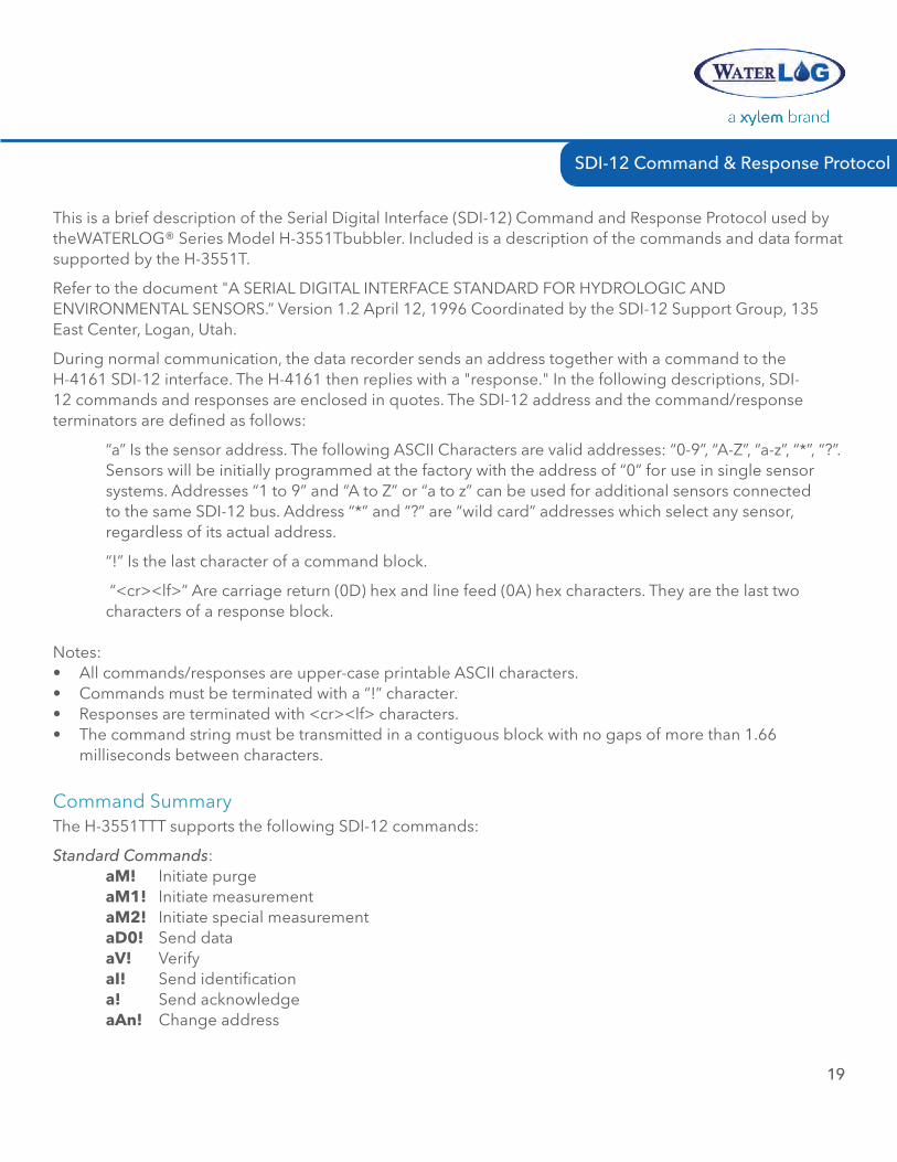
SDI-12 Command & Response Protocol
This is a brief description of the Serial Digital Interface (SDI-12) Command and Response Protocol used by theWATERLOG® Series Model H-3551Tbubbler. Included is a description of the commands and data format supported by the H-3551T.
Refer to the document "A SERIAL DIGITAL INTERFACE STANDARD FOR HYDROLOGIC AND ENVIRONMENTAL SENSORS.” Version 1.2 April 12, 1996 Coordinated by the SDI-12 Support Group, 135 East Center, Logan, Utah.
During normal communication, the data recorder sends an address together with a command to the H-4161 SDI-12 interface. The H-4161 then replies with a "response." In the following descriptions, SDI-12 commands and responses are enclosed in quotes. The SDI-12 address and the command/response terminators are defined as follows:
“a” Is the sensor address. The following ASCII Characters are valid addresses: “0-9”, “A-Z”, “a-z”, “*”, “?”. Sensors will be initially programmed at the factory with the address of “0” for use in single sensor systems. Addresses “1 to 9” and “A to Z” or “a to z” can be used for additional sensors connected to the same SDI-12 bus. Address “*” and “?” are “wild card” addresses which select any sensor, regardless of its actual address.
“!” Is the last character of a command block.
“<cr><lf>” Are carriage return (0D) hex and line feed (0A) hex characters. They are the last two characters of a response block.
Notes:• All commands/responses are upper-case printable ASCII characters.• Commands must be terminated with a “!” character.• Responses are terminated with <cr><lf> characters.• The command string must be transmitted in a contiguous block with no gaps of more than 1.66
milliseconds between characters.
The H-3551TTT supports the following SDI-12 commands:
Standard Commands: am! Initiate purge am1! Initiate measurement am2! Initiate special measurement aD0! Send data aV! Verify aI! Send identification a! Send acknowledge aan! Change address
Command Summary
20
SDI-12 COMMAND & RESPONSE
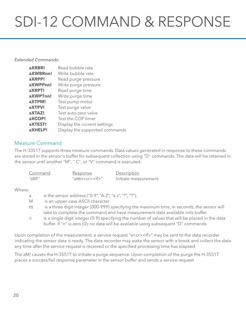
Extended Commands:
aXrBr! Read bubble rate aXwBrnn! Write bubble rate aXrPP! Read purge pressure aXwPPnn! Write purge pressure aXrPT! Read purge time aXwPTnn! Write purge time aXTPm! Test pump motor aXTPV! Test purge valve aXTaZ! Test auto-zero valve aXCOP! Test the COP timer aXTesT! Display the current settings aXHelP! Display the supported commands
Measure CommandThe H-3351T supports three measure commands. Data values generated in response to these commands are stored in the sensor's buffer for subsequent collection using "D" commands. The data will be retained in the sensor until another "M", " C", or "V" command is executed.
Command Response Description “aM!” “atttn<cr><lf>” Initiate measurement
Where: a is the sensor address (“0-9”, “A-Z”, “a-z”, “*”, “?”). M is an upper-case ASCII character ttt is a three digit integer (000-999) specifying the maximum time, in seconds, the sensor will take to complete the command and have measurement data available inits buffer. n is a single digit integer (0-9) specifying the number of values that will be placed in the data buffer. If “n” is zero (0), no data will be available using subsequent “D” commands
Upon completion of the measurement, a service request “a<cr><lf>” may be sent to the data recorder indicating the sensor data is ready. The data recorder may wake the sensor with a break and collect the data any time after the service request is received or the specified processing time has elapsed.
The aM! causes the H-3551T to initiate a purge sequence. Upon completion of the purge the H-3551T places a success/fail response parameter in the sensor buffer and sends a service request
SDI-12 Command & Response Protocol
21
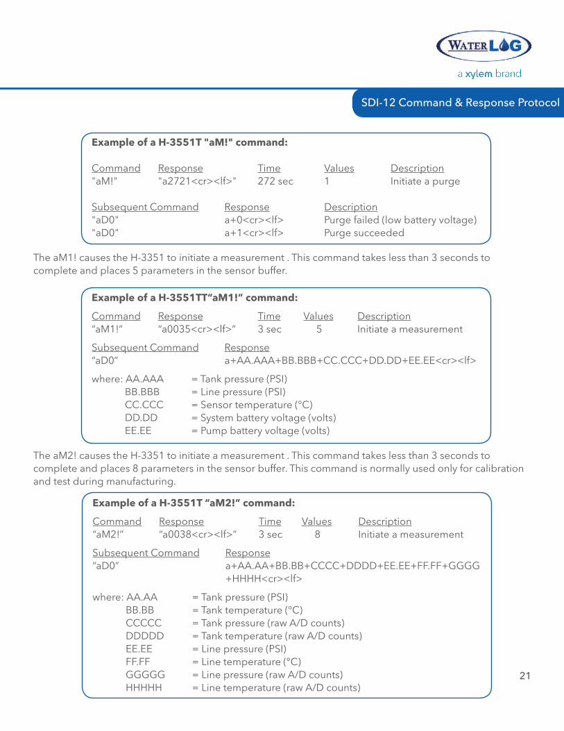
example of a H-3551T "am!" command:
Command Response Time Values Description"aM!" "a2721<cr><lf>" 272 sec 1 Initiate a purge
Subsequent Command Response Description"aD0" a+0<cr><lf> Purge failed (low battery voltage)"aD0" a+1<cr><lf> Purge succeeded
The aM1! causes the H-3351 to initiate a measurement . This command takes less than 3 seconds to complete and places 5 parameters in the sensor buffer.
example of a H-3551TT“am1!” command:
Command Response Time Values Description“aM1!” “a0035<cr><lf>” 3 sec 5 Initiate a measurement
Subsequent Command Response“aD0” a+AA.AAA+BB.BBB+CC.CCC+DD.DD+EE.EE<cr><lf>
where: AA.AAA = Tank pressure (PSI) BB.BBB = Line pressure (PSI) CC.CCC = Sensor temperature (°C) DD.DD = System battery voltage (volts) EE.EE = Pump battery voltage (volts)
The aM2! causes the H-3351 to initiate a measurement . This command takes less than 3 seconds to complete and places 8 parameters in the sensor buffer. This command is normally used only for calibration and test during manufacturing.
example of a H-3551T “am2!” command:
Command Response Time Values Description“aM2!” “a0038<cr><lf>” 3 sec 8 Initiate a measurement
Subsequent Command Response“aD0” a+AA.AA+BB.BB+CCCC+DDDD+EE.EE+FF.FF+GGGG +HHHH<cr><lf>
where: AA.AA = Tank pressure (PSI) BB.BB = Tank temperature (°C) CCCCC = Tank pressure (raw A/D counts) DDDDD = Tank temperature (raw A/D counts) EE.EE = Line pressure (PSI) FF.FF = Line temperature (°C) GGGGG = Line pressure (raw A/D counts) HHHHH = Line temperature (raw A/D counts)
22
SDI-12 COMMAND & RESPONSE
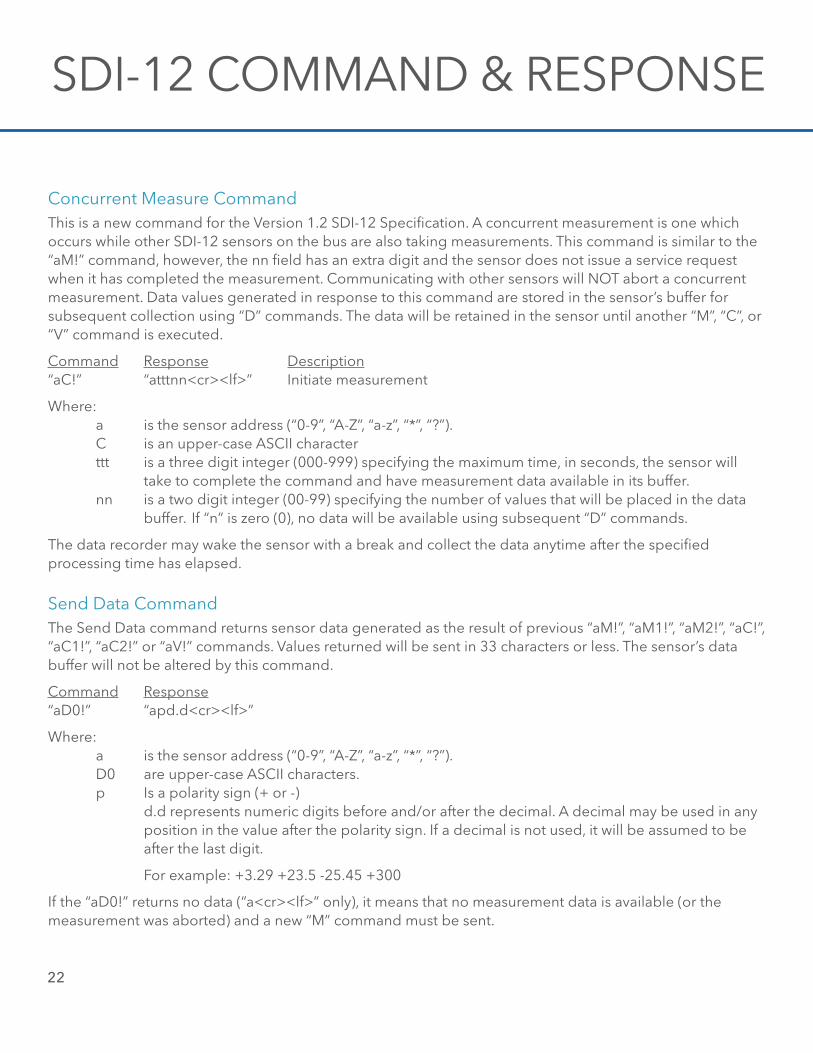
Concurrent Measure CommandThis is a new command for the Version 1.2 SDI-12 Specification. A concurrent measurement is one which occurs while other SDI-12 sensors on the bus are also taking measurements. This command is similar to the “aM!” command, however, the nn field has an extra digit and the sensor does not issue a service request when it has completed the measurement. Communicating with other sensors will NOT abort a concurrent measurement. Data values generated in response to this command are stored in the sensor’s buffer forsubsequent collection using “D” commands. The data will be retained in the sensor until another “M”, “C”, or “V” command is executed.
Command Response Description“aC!” “atttnn<cr><lf>” Initiate measurement
Where: a is the sensor address (“0-9”, “A-Z”, “a-z”, “*”, “?”). C is an upper-case ASCII character ttt is a three digit integer (000-999) specifying the maximum time, in seconds, the sensor will take to complete the command and have measurement data available in its buffer. nn is a two digit integer (00-99) specifying the number of values that will be placed in the data buffer. If “n” is zero (0), no data will be available using subsequent “D” commands.
The data recorder may wake the sensor with a break and collect the data anytime after the specified processing time has elapsed.
Send Data CommandThe Send Data command returns sensor data generated as the result of previous “aM!”, “aM1!”, “aM2!”, “aC!”, “aC1!”, “aC2!” or “aV!” commands. Values returned will be sent in 33 characters or less. The sensor’s data buffer will not be altered by this command.
Command Response“aD0!” “apd.d<cr><lf>”
Where: a is the sensor address (“0-9”, “A-Z”, “a-z”, “*”, “?”). D0 are upper-case ASCII characters. p Is a polarity sign (+ or -) d.d represents numeric digits before and/or after the decimal. A decimal may be used in any position in the value after the polarity sign. If a decimal is not used, it will be assumed to be after the last digit.
For example: +3.29 +23.5 -25.45 +300
If the “aD0!” returns no data (“a<cr><lf>” only), it means that no measurement data is available (or the measurement was aborted) and a new “M” command must be sent.
SDI-12 Command & Response Protocol
23
example of a H-3551T “aD0!” command:
Previous Command Response“aM!” “a2721<cr><lf>”
Subsequent Command Response Description“aD0” a+0<cr><lf> Purge failed (low battery)“aD0” a+1<cr><lf> Purge succeeded
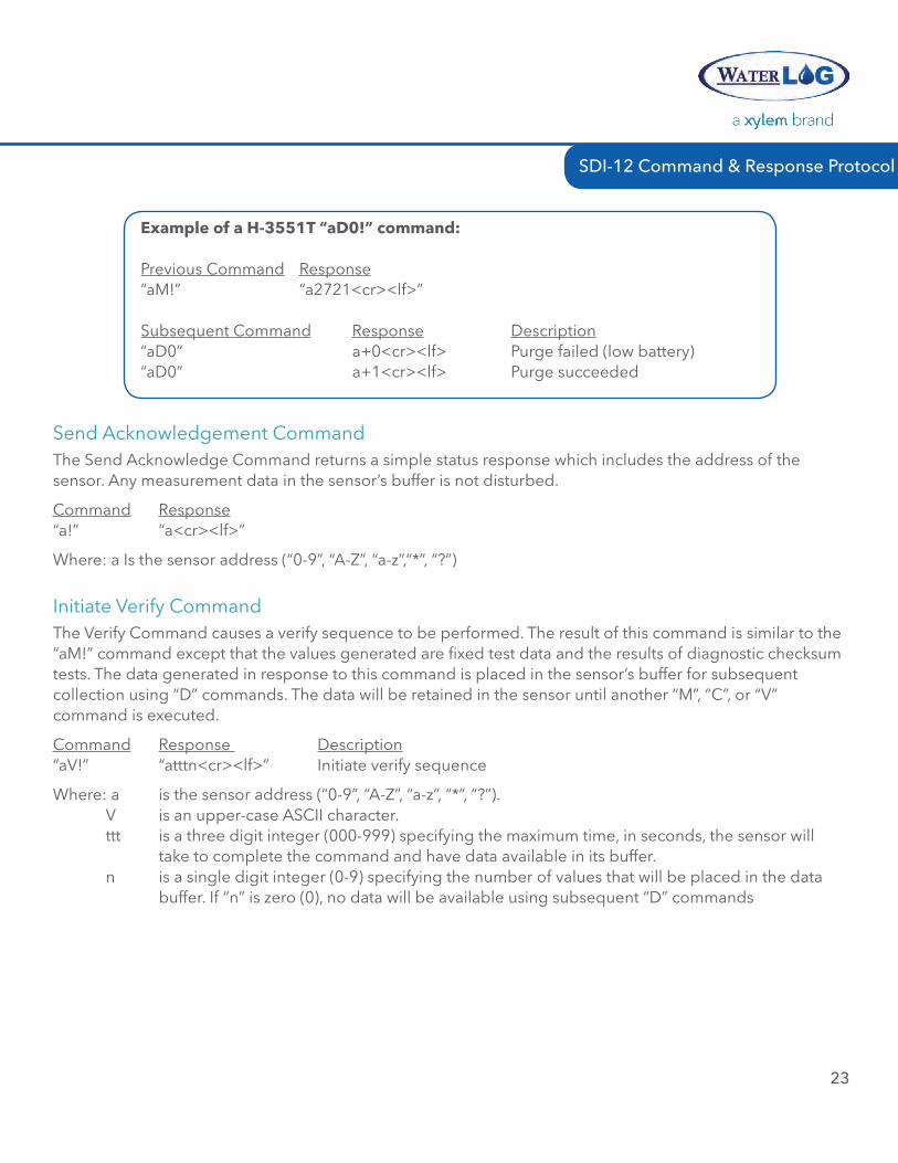
Send Acknowledgement CommandThe Send Acknowledge Command returns a simple status response which includes the address of the sensor. Any measurement data in the sensor’s buffer is not disturbed.
Command Response “a!” “a<cr><lf>”
Where: a Is the sensor address (“0-9”, “A-Z”, “a-z”,“*”, “?”)
Initiate Verify CommandThe Verify Command causes a verify sequence to be performed. The result of this command is similar to the “aM!” command except that the values generated are fixed test data and the results of diagnostic checksum tests. The data generated in response to this command is placed in the sensor’s buffer for subsequent collection using “D” commands. The data will be retained in the sensor until another “M”, “C”, or “V” command is executed.
Command Response Description “aV!” “atttn<cr><lf>” Initiate verify sequence
Where: a is the sensor address (“0-9”, “A-Z”, “a-z”, “*”, “?”). V is an upper-case ASCII character. ttt is a three digit integer (000-999) specifying the maximum time, in seconds, the sensor will take to complete the command and have data available in its buffer. n is a single digit integer (0-9) specifying the number of values that will be placed in the data buffer. If “n” is zero (0), no data will be available using subsequent “D” commands
24
SDI-12 COMMAND & RESPONSE
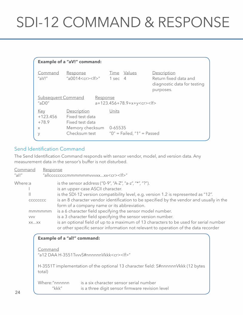
example of a “aV!” command:
Command Response Time Values Description“aV!” “a0014<cr><lf>” 1 sec 4 Return fixed data and diagnostic data for testing purposes.
Subsequent Command Response “aD0” a+123.456+78.9+x+y<cr><lf>
Key Description Units+123.456 Fixed test data+78.9 Fixed test datax Memory checksum 0-65535y Checksum test “0” = Failed, “1” = Passed
Send Identification CommandThe Send Identification Command responds with sensor vendor, model, and version data. Any measurement data in the sensor’s buffer is not disturbed.
Command Response“aI!” “allccccccccmmmmmmvvvxx...xx<cr><lf>”
Where:a is the sensor address (“0-9”, “A-Z”, “a-z”, “*”, “?”). I is an upper-case ASCII character. ll is the SDI-12 version compatibility level, e.g. version 1.2 is represented as “12”. cccccccc is an 8 character vendor identification to be specified by the vendor and usually in the form of a company name or its abbreviation. mmmmmm is a 6 character field specifying the sensor model number. vvv is a 3 character field specifying the sensor version number. xx...xx is an optional field of up to a maximum of 13 characters to be used for serial number or other specific sensor information not relevant to operation of the data recorder
example of a “al!” command:
Command “a12 DAA H-3551TvvvS#nnnnnnVkkk<cr><lf>”
H-3551T implementation of the optional 13 character field: S#nnnnnnVkkk (12 bytes total)
Where:“nnnnnn is a six character sensor serial number “kkk” is a three digit sensor firmware revision level
SDI-12 Command & Response Protocol
25
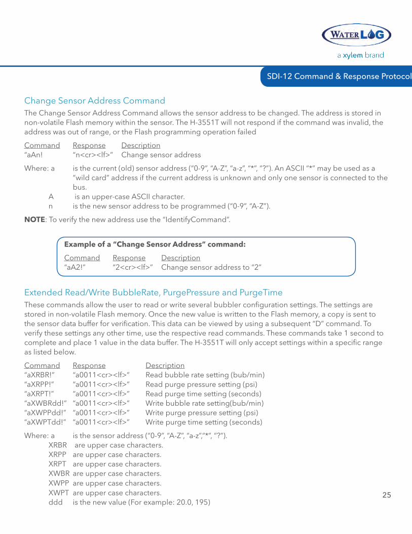
Change Sensor Address CommandThe Change Sensor Address Command allows the sensor address to be changed. The address is stored in non-volatile Flash memory within the sensor. The H-3551T will not respond if the command was invalid, the address was out of range, or the Flash programming operation failed
Command Response Description“aAn! “n<cr><lf>” Change sensor address
Where: a is the current (old) sensor address (“0-9”, “A-Z”, “a-z”, “*”, “?”). An ASCII “*” may be used as a “wild card” address if the current address is unknown and only one sensor is connected to the bus. A is an upper-case ASCII character. n is the new sensor address to be programmed (“0-9”, “A-Z”).
nOTe: To verify the new address use the “IdentifyCommand”.
example of a “Change sensor address” command:
Command Response Description“aA2!” “2<cr><lf>” Change sensor address to “2”
Extended Read/Write BubbleRate, PurgePressure and PurgeTimeThese commands allow the user to read or write several bubbler configuration settings. The settings are stored in non-volatile Flash memory. Once the new value is written to the Flash memory, a copy is sent to the sensor data buffer for verification. This data can be viewed by using a subsequent “D” command. To verify these settings any other time, use the respective read commands. These commands take 1 second to complete and place 1 value in the data buffer. The H-3551T will only accept settings within a specific range as listed below.
Command Response Description“aXRBR!” “a0011<cr><lf>” Read bubble rate setting (bub/min)“aXRPP!” “a0011<cr><lf>” Read purge pressure setting (psi)“aXRPT!” “a0011<cr><lf>” Read purge time setting (seconds)“aXWBRdd!” “a0011<cr><lf>” Write bubble rate setting(bub/min)“aXWPPdd!” “a0011<cr><lf>” Write purge pressure setting (psi)“aXWPTdd!” “a0011<cr><lf>” Write purge time setting (seconds)
Where: a is the sensor address (“0-9”, “A-Z”, “a-z”,“*”, “?”). XRBR are upper case characters. XRPP are upper case characters. XRPT are upper case characters. XWBR are upper case characters. XWPP are upper case characters. XWPT are upper case characters. ddd is the new value (For example: 20.0, 195)
26
SDI-12 COMMAND & RESPONSE
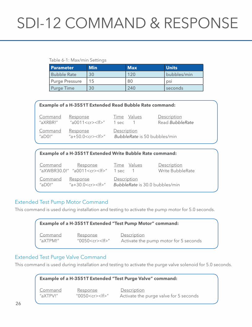
Parameter min max unitsBubble Rate 30 120 bubbles/minPurge Pressure 15 80 psi
Purge Time 30 240 seconds
Table 6-1: Max/min Settings
example of a H-3551T extended read Bubble rate command:
Command Response Time Values Description“aXRBR!” “a0011<cr><lf>” 1 sec 1 Read BubbleRate
Command Response Description “aD0!” “a+50.0<cr><lf>” BubbleRate is 50 bubbles/min
example of a H-3551T extended write Bubble rate command:
Command Response Time Values Description“aXWBR30.0!” “a0011<cr><lf>” 1 sec 1 Write BubbleRate
Command Response Description “aD0!” “a+30.0<cr><lf>” BubbleRate is 30.0 bubbles/min
Extended Test Pump Motor CommandThis command is used during installation and testing to activate the pump motor for 5.0 seconds.
example of a H-3551T extended “Test Pump motor” command:
Command Response Description“aXTPM!” “0050<cr><lf>” Activate the pump motor for 5 seconds
Extended Test Purge Valve CommandThis command is used during installation and testing to activate the purge valve solenoid for 5.0 seconds.
example of a H-3551T extended “Test Purge Valve” command:
Command Response Description“aXTPV!” “0050<cr><lf>” Activate the purge valve for 5 seconds
SDI-12 Command & Response Protocol
27
Extended Test Auto-Zero Valve CommandThis command is used during installation and testing to activate the auto-zero valve solenoid for 5.0 seconds.
example of a H-3551T extended “Test auto-Zero Valve” command:
Command Response Description“aXTAZ!” “0050<cr><lf>” Activate the auto-zero valve for 5 seconds
Extended Test COP (Computer Operating Properly) Timer CommandThis command causes the COP timer to expire which in turn should initiate a system reset.
example of a H-3551T extended “Test COP Timer” command:
Command Response Description“aXCOPT!” “0050<cr><lf>” Test the COP timer
Extended “XTEST” CommandThis command is used for installation and testing and requires the use of a H-4191 Sidekick interface and a PC. This command causes the H-3551T to display a listing of the H-3551T’s current settings, followed by a repeating printout of real-time measurement data. This is not compliant with the SDI-12 specification and is not used with data loggers.
An example of an “XTEST” printout is shown below:
H-3551 Settings: Firmware Checksum = PASS Bubbler Mode = Remote Host Bubble Rate (bub/s) = 60 Hysteresis (psi) = 0.50 Purge Pressure (psi) = 40.00 Purge Threshold (psi)= 20.00 Purge Time (sec) = 45 AZ Interval (min) = 30
Tank_PSI=xx.xxx, Tank_TEMP=xx.xx, Tank_Vp=xxxxx, Tank_Vt=xxxxxLine_PSI=xx.xxx, Line_TEMP=xx.xx, Line_Vp=xxxxx, Line_Vt=xxxxx
Tank_PSI=xx.xxx, Tank_TEMP=xx.xx, Tank_Vp=xxxxx, Tank_Vt=xxxxxLine_PSI=xx.xxx, Line_TEMP=xx.xx, Line_Vp=xxxxx, Line_Vt=xxxxx
Tank_PSI=xx.xxx, Tank_TEMP=xx.xx, Tank_Vp=xxxxx, Tank_Vt=xxxxxLine_PSI=xx.xxx, Line_TEMP=xx.xx, Line_Vp=xxxxx, Line_Vt=xxxxx
etc.
28
SDI-12 COMMAND & RESPONSE
Extended “XHELP” CommandThis command is used for installation and testing and requires the use of a H-4191 Sidekick interface and a PC. This command causes the H-3551T to display a listing of the supported SDI-12 commands. This is not compliant with the SDI-12 specification and is not used with data loggers.
An example of the “XHELP” printout is shown below:
H-3551 SDI-12 Commands:M Initiate Purge (aM!)M1 Make measurement (aM1!) (TankPSI:LinePSI:Temperature:SysBat:PumpBat)M2 Make measurement (aM2!) (TankPSI:TankTemp:TankVp:TankVt:LinePSI:LineTemp:LineVp:LineVt)D Send Data (aD0!)V Verify (aV!)I Send Identification (aI!)! Send Acknowledge (a!)An Change Address (aAn!)
Extended Commands:XRBR Read bubble rateXWBRnn Write bubble rateXRPP Read purge pressureXWPPnn Write purge pressureXRPT Read purge timeXWPTnn Write purge time
XTPM Test pump motorXTPV Test purge valveXTZV Test auto-zero valveXCOPT Test COP timerXTEST Make repeating measurementsXHELP Print this listing
29
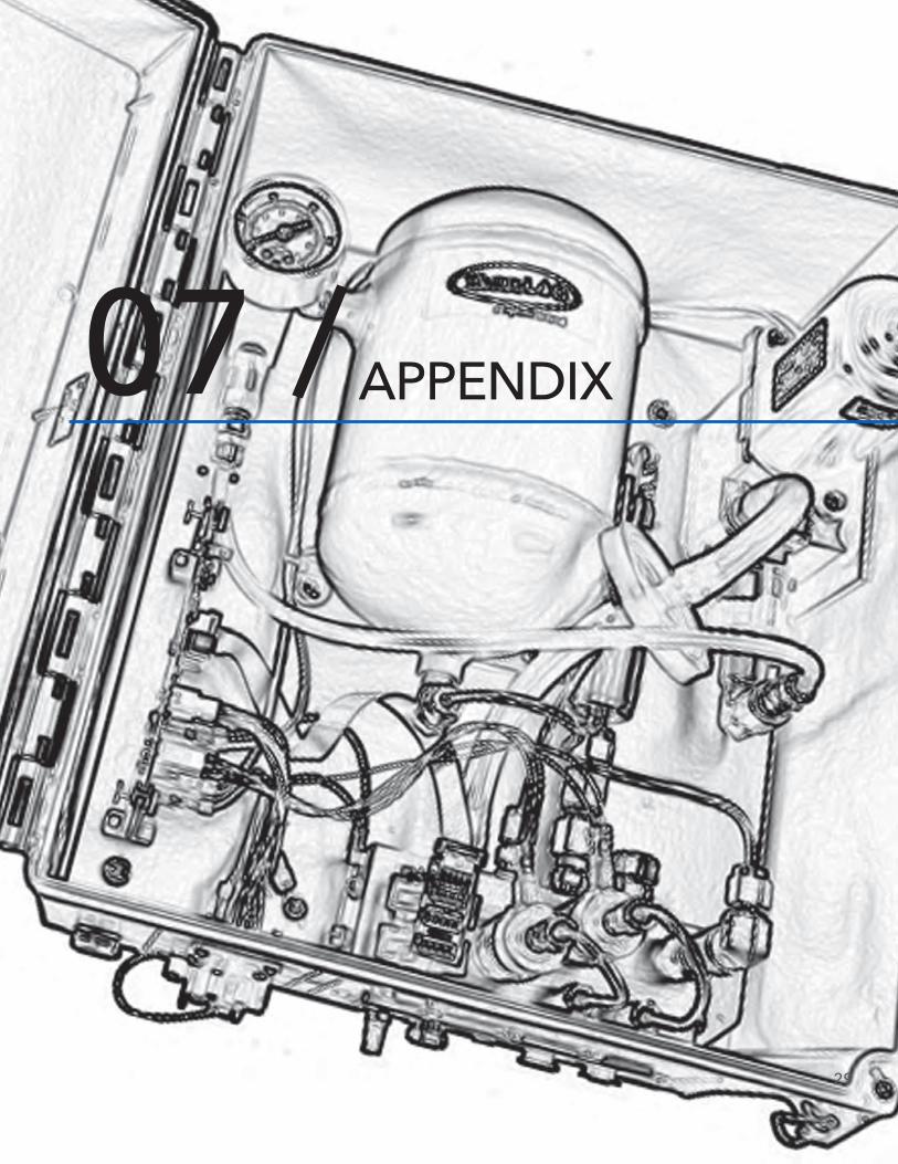
APPENDIX07 /
enVIrOnmenTal
standard Operating range
-40° to 60° C
storage -50° to 80° C
It is recommended the H-3551T be installed in a weather shielded enclosure (gauge station)
Gas DelIVerY
Control system Microprocessor controlled
Technology Constant mass flow
Gas Flow Control Bubble rate is user selectable from 30 to 120 bubbles per minute. Built-in auto zero compensation. No needle valve (patent application in process)
COmPressOr
Type HI-REL medical grade ISO 9003 qualified piston compressor (avoids broken diaphragm problems) Serviced for extended temperature operation
Operation Low duty cycle 5 hours typical runtime per year at 60bubbles per minute
Pumping Time 1-second (average)
PurGe FunCTIOns
Purge Pressure User selectable 15 PSI to 80 PSI
Options 1. Manual
2. Internally sensed
3. Automatic timed interval
4. Remote controlled
COnTrOl InTerFaCe
Type RS-485
Protocol ASCII
Baud rate 9600 bps, half-duplex, 8 bit, no parity, 1 stop bit
POwer
Qualified for operation with a 12-volt battery
supply Inputs 1. Electronics supply via the RS-485 cable
2. Compressor supply
Voltage 10 to 16 volts
Current 15 milliamperes average (@ 60 bub/min)
max Current 3.0A (pump running)
Appendix A: Specifications
PHYsICal
enclosure Corrosion resistant, Type 4X molded fiberglass, hinged cover, sleamless foam-in-place gasket
size 10.5 in. W x 12.5 in. L x 6.0 in. D
weight 12 lbs
mounting Hardware supplied for wall mounting
Pressure Outlet 1/8 in. FNPT
sensor Pressure Outlet
1.8 in. FNPT
air Intake 1/8 in. FNPT
Pressure relief valve
Internal
mIsCellaneOus
Ordering Information
H-3551 Base model
H-3551/000 Standard H-355 “smart gas” system
H-3551/350 Combination H-3551 “smart gas” system and H-350 pressure measurement system
warranty The WaterLOG® H-3611/H-3612/H-3613 series radars are warranted against defects in materials and workmanship for two years from date of shipment.
notes Specifications subject to change without prior noticedue to ongoing commitment to product testing andimprovement. LR June 17, 2013 (D4 0613)
30
APPENDIX
Appendix
31
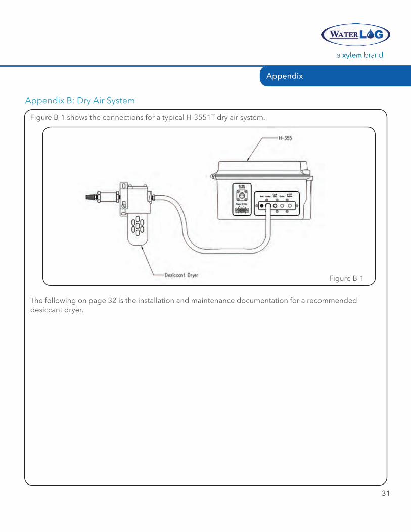
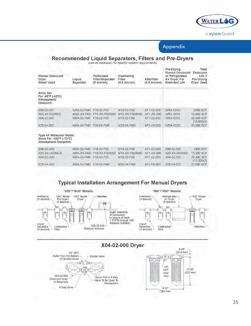
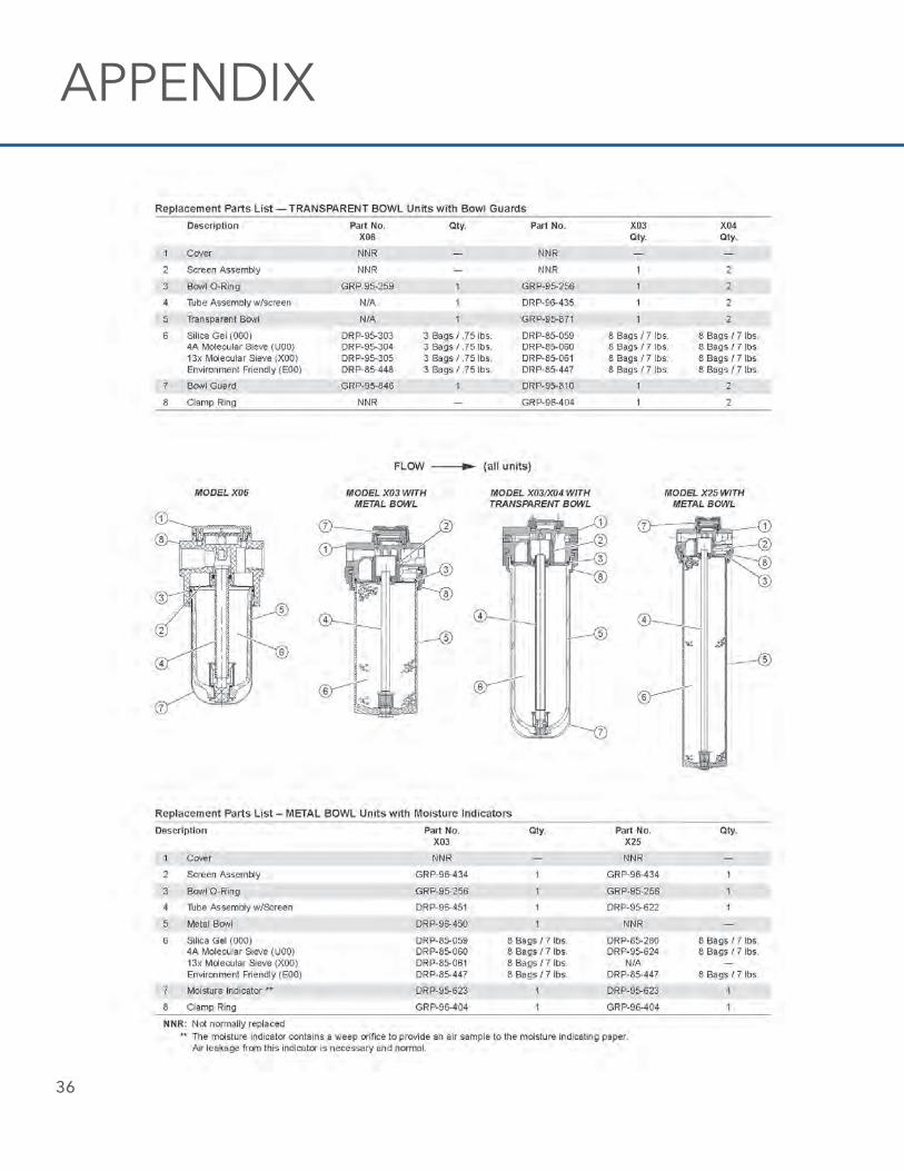
Appendix B: Dry Air System
Figure B-1 shows the connections for a typical H-3551T dry air system.
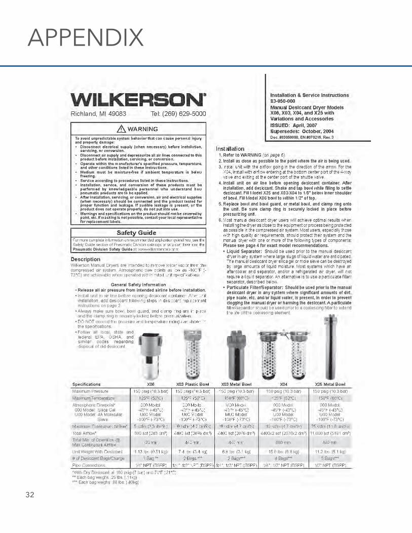
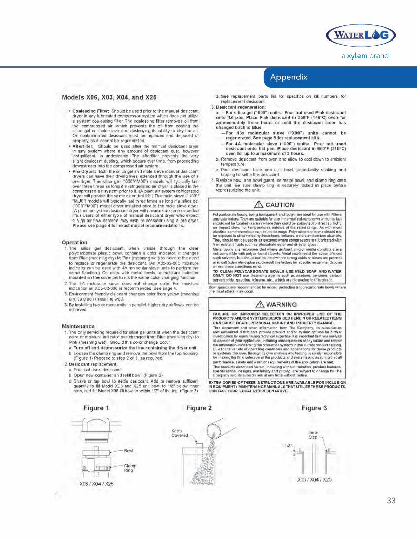
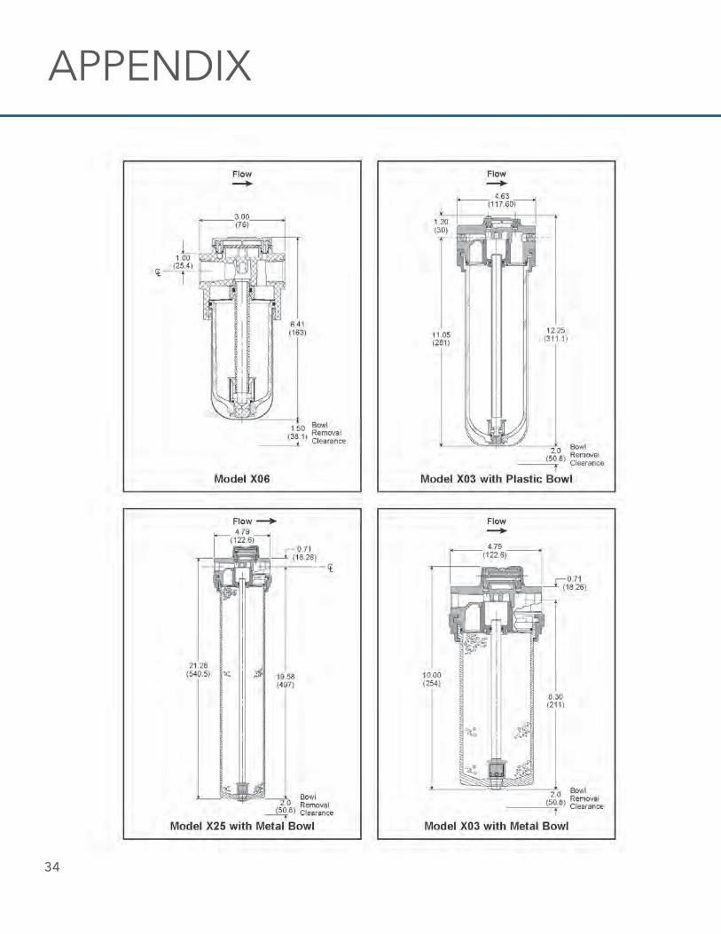
The following on page 32 is the installation and maintenance documentation for a recommended desiccant dryer.
Figure B-1
32
APPENDIX
33
Appendix
34
APPENDIX
35
Appendix
36
APPENDIX
37
Appendix
1) The tissue in plants that brings water upward from the roots;2) a leading global water technology company.
We’re 12,000 people unified in a common purpose: creating innovative solutionsto meet our world’s water needs. Developing new technologies that will improvethe way water is used, conserved, and re-used in the future is central to our work.We move, treat, analyze, and return water to the environment, and we help peopleuse water efficiently, in their homes, buildings, factories and farms. In more than150 countries, we have strong, long-standing relationships with customers whoknow us for our powerful combination of leading product brands and applicationsexpertise, backed by a legacy of innovation.
For more information on how Xylem can help you, go to www.xyleminc.com
Xylem
H-3551T is a trademark of Xylem Inc. or one of its subsidiaries. © 2014 Xylem, Inc. D46 0814
Xylem—WaterLOG1700/1725 Brannum LaneYellow Springs, Ohio45387, USATel +1.435.753.2212Fax +1.435.753.7669www.waterlog.com