Embed Size (px)
Citation preview
craft have used the free spinning rotor to attainperformance not available in the pure helicopter.The “gyrodyne” is a hybrid rotorcraft that is capa-ble of hovering and yet cruises in autorotation.The first successful example of this type of aircraftwas the British Fairy Rotodyne, certificated to theTransport Category in 1958. During the 1960s and1970s, the popularity of gyroplanes increased withthe certification of the McCulloch J-2 andUmbaugh. The latter becoming the Air & Space18A.
There are several aircraft under developmentusing the free spinning rotor to achieve rotary wingtakeoff performance and fixed wing cruise speeds.The gyroplane offers inherent safety, simplicity ofoperation, and outstanding short field point-to-point capability.
TYPES OF GYROPLANESBecause the free spinning rotor does notrequire an antitorque device, a single rotor isthe predominate configuration. Counter-rotatingblades do not offer any particular advantage.The rotor system used in a gyroplane may haveany number of blades, but the most popular arethe two and three blade systems. Propulsion forgyroplanes may be either tractor or pusher,meaning the engine may be mounted on thefront and pull the aircraft, or in the rear, pushingit through the air. The powerplant itself may beeither reciprocating or turbine. Early gyroplaneswere often a derivative of tractor configured air-
January 9th, 1923, marked the first officiallyobserved flight of an autogyro. The aircraft,designed by Juan de la Cierva, introduced rotortechnology that made forward flight in a rotorcraftpossible. Until that time, rotary-wing aircraftdesigners were stymied by the problem of a rollingmoment that was encountered when the aircraftbegan to move forward. This rolling moment wasthe product of airflow over the rotor disc, causingan increase in lift of the advancing blade anddecrease in lift of the retreating blade. Cierva’ssuccessful design, the C.4, introduced the articu-lated rotor, on which the blades were hinged andallowed to flap. This solution allowed the advanc-ing blade to move upward, decreasing angle ofattack and lift, while the retreating blade wouldswing downward, increasing angle of attack andlift. The result was balanced lift across the rotordisc regardless of airflow. This breakthrough wasinstrumental in the success of the modern helicop-ter, which was developed over 15 years later. (Formore information on dissymmetry of lift, refer toChapter 3—Aerodynamics of Flight.) On April 2,1931, the Pitcairn PCA-2 autogyro was grantedType Certificate No. 410 and became the firstrotary wing aircraft to be certified in the UnitedStates. The term “autogyro” was used to describethis type of aircraft until the FAA later designatedthem “gyroplanes.”
By definition, the gyroplane is an aircraft thatachieves lift by a free spinning rotor. Several air-
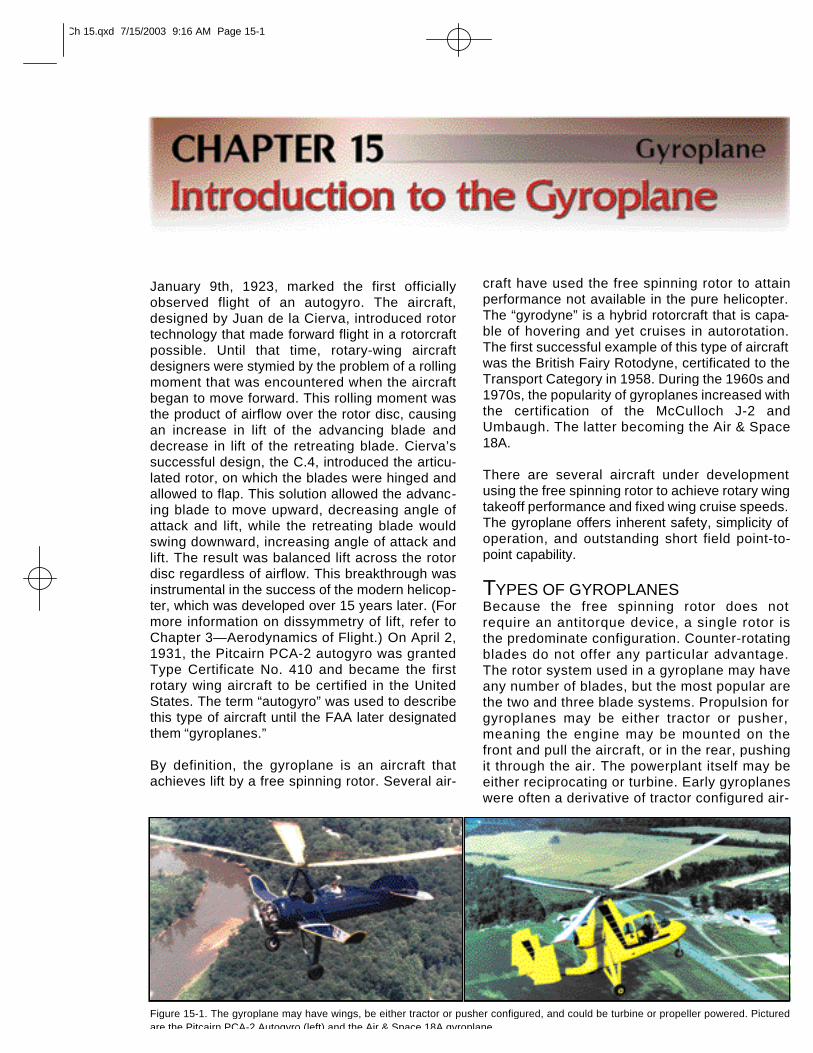
Figure 15-1. The gyroplane may have wings, be either tractor or pusher configured, and could be turbine or propeller powered. Picturedare the Pitcairn PCA-2 Autogyro (left) and the Air & Space 18A gyroplane.
Ch 15.qxd 7/15/2003 9:16 AM Page 15-1
planes with the rotor either replacing the wingor acting in conjunction with it. However, thepusher configuration is generally more maneu-verable due to the placement of the rudder inthe propeller slipstream, and also has theadvantage of better visibility for the pilot.[Figure 15-1]
When direct control of the rotor head was per-fected, the jump takeoff gyroplane was devel-oped. Under the proper conditions, thesegyroplanes have the ability to lift off vertically andtransition to forward flight. Later developmentshave included retaining the direct control rotorhead and utilizing a wing to unload the rotor,which results in increased forward speed.
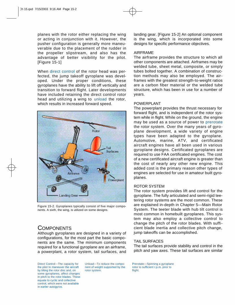
COMPONENTSAlthough gyroplanes are designed in a variety ofconfigurations, for the most part the basic compo-nents are the same. The minimum componentsrequired for a functional gyroplane are an airframe,a powerplant, a rotor system, tail surfaces, and
Direct Control—The capacity forthe pilot to maneuver the aircraftby tilting the rotor disc and, onsome gyroplanes, affect changesin pitch to the rotor blades. Theseequate to cyclic and collectivecontrol, which were not availablein earlier autogyros.
Unload—To reduce the compo-nent of weight supported by therotor system.
Prerotate—Spinning a gyroplanerotor to sufficient r.p.m. prior toflight.
landing gear. [Figure 15-2] An optional componentis the wing, which is incorporated into somedesigns for specific performance objectives.
AIRFRAMEThe airframe provides the structure to which allother components are attached. Airframes may bewelded tube, sheet metal, composite, or simplytubes bolted together. A combination of construc-tion methods may also be employed. The air-frames with the greatest strength-to-weight ratiosare a carbon fiber material or the welded tubestructure, which has been in use for a number ofyears.
POWERPLANTThe powerplant provides the thrust necessary forforward flight, and is independent of the rotor sys-tem while in flight. While on the ground, the enginemay be used as a source of power to prerotatethe rotor system. Over the many years of gyro-plane development, a wide variety of enginetypes have been adapted to the gyroplane.Automotive, marine, ATV, and certificated aircraft engines have all been used in various gyroplane designs. Certificated gyroplanes arerequired to use FAA certificated engines. The costof a new certificated aircraft engine is greater thanthe cost of nearly any other new engine. Thisadded cost is the primary reason other types ofengines are selected for use in amateur built gyro-planes.
ROTOR SYSTEMThe rotor system provides lift and control for thegyroplane. The fully articulated and semi-rigid tee-tering rotor systems are the most common. Theseare explained in-depth in Chapter 5—Main RotorSystem. The teeter blade with hub tilt control ismost common in homebuilt gyroplanes. This sys-tem may also employ a collective control tochange the pitch of the rotor blades. With suffi -cient blade inertia and collective pitch change,jump takeoffs can be accomplished.
TAIL SURFACESThe tail surfaces provide stability and control in thepitch and yaw axes. These tail surfaces are similar
Figure 15-2. Gyroplanes typically consist of five major compo-nents. A sixth, the wing, is utilized on some designs.
Ch 15.qxd 7/15/2003 9:16 AM Page 15-2
to an airplane empennage and may be comprisedof a fin and rudder, stabilizer and elevator. An aftmounted duct enclosing the propeller and rudderhas also been used. Many gyroplanes do not incor-porate a horizontal tail surface.
On some gyroplanes, especially those with anenclosed cockpit, the yaw stability is marginal dueto the large fuselage side area located ahead ofthe center of gravity. The additional vertical tailsurface necessary to compensate for this instabil-ity is difficult to achieve as the confines of the rotortilt and high landing pitch attitude limits the avail-able area. Some gyroplane designs incorporatemultiple vertical stabilizers and rudders to addadditional yaw stability.
LANDING GEARThe landing gear provides the mobility while on theground and may be either conventional or tricycle.
Conventional gear consists of two main wheels,and one under the tail. The tricycle configurationalso uses two mains, with the third wheel under thenose. Early autogyros, and several models of gyro-planes, use conventional gear, while most of thelater gyroplanes incorporate tricycle landing gear.As with fixed wing aircraft, the gyroplane landinggear provides the ground mobility not found inmost helicopters.
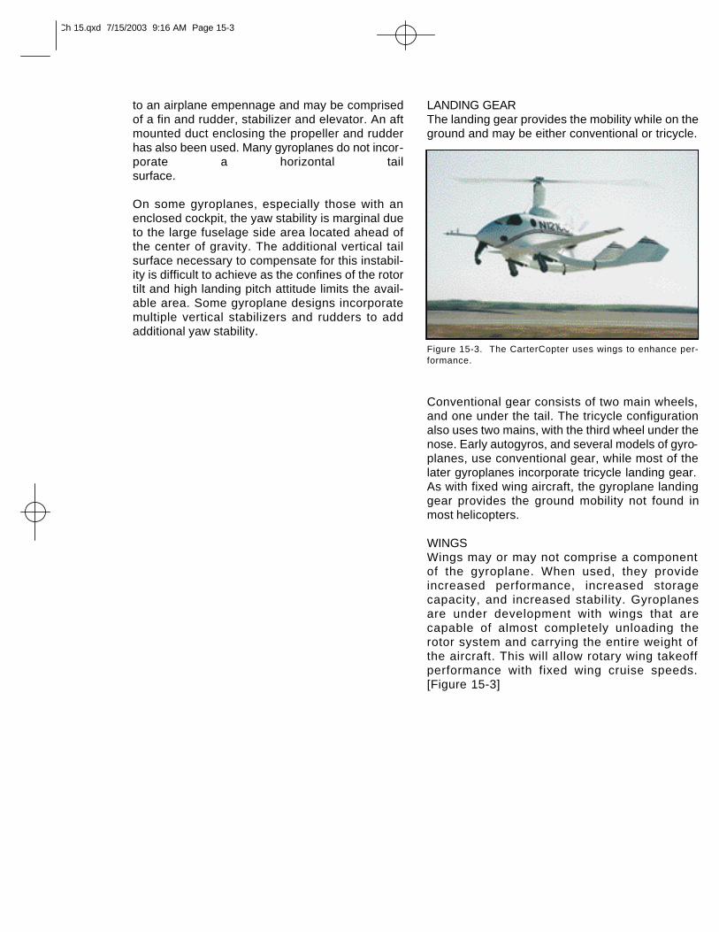
WINGSWings may or may not comprise a componentof the gyroplane. When used, they provideincreased performance, increased storagecapacity, and increased stability. Gyroplanesare under development with wings that arecapable of almost completely unloading therotor system and carrying the entire weight ofthe aircraft. This will allow rotary wing takeoffperformance with fixed wing cruise speeds.[Figure 15-3]
Figure 15-3. The CarterCopter uses wings to enhance per-formance.
Ch 15.qxd 7/15/2003 9:16 AM Page 15-3
Helicopters and gyroplanes both achieve liftthrough the use of airfoils, and, therefore, many ofthe basic aerodynamic principles governing theproduction of lift apply to both aircraft. These con-cepts are explained in depth in Chapter 2—General Aerodynamics, and constitute thefoundation for discussing the aerodynamics of agyroplane.
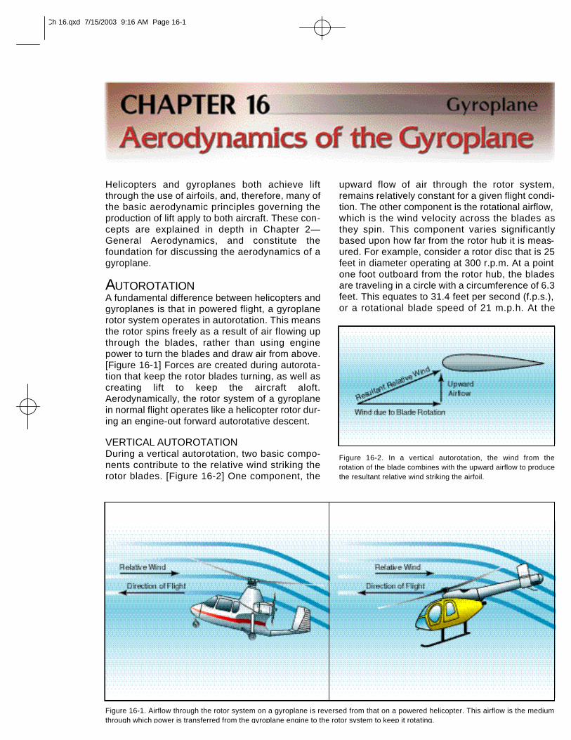
AUTOROTATIONA fundamental difference between helicopters andgyroplanes is that in powered flight, a gyroplanerotor system operates in autorotation. This meansthe rotor spins freely as a result of air flowing upthrough the blades, rather than using enginepower to turn the blades and draw air from above.[Figure 16-1] Forces are created during autorota-tion that keep the rotor blades turning, as well ascreating lift to keep the aircraft aloft.Aerodynamically, the rotor system of a gyroplanein normal flight operates like a helicopter rotor dur-ing an engine-out forward autorotative descent.
VERTICAL AUTOROTATIONDuring a vertical autorotation, two basic compo-nents contribute to the relative wind striking therotor blades. [Figure 16-2] One component, the
upward flow of air through the rotor system,remains relatively constant for a given flight condi-tion. The other component is the rotational airflow,which is the wind velocity across the blades asthey spin. This component varies significantlybased upon how far from the rotor hub it is meas-ured. For example, consider a rotor disc that is 25feet in diameter operating at 300 r.p.m. At a pointone foot outboard from the rotor hub, the bladesare traveling in a circle with a circumference of 6.3feet. This equates to 31.4 feet per second (f.p.s.),or a rotational blade speed of 21 m.p.h. At the
Figure 16-1. Airflow through the rotor system on a gyroplane is reversed from that on a powered helicopter. This airflow is the mediumthrough which power is transferred from the gyroplane engine to the rotor system to keep it rotating.
Figure 16-2. In a vertical autorotation, the wind from the rotation of the blade combines with the upward airflow to producethe resultant relative wind striking the airfoil.
Ch 16.qxd 7/15/2003 9:16 AM Page 16-1
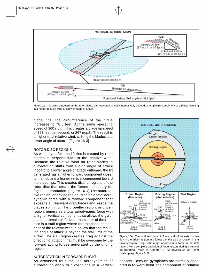
blade tips, the circumference of the circleincreases to 78.5 feet. At the same operatingspeed of 300 r.p.m., this creates a blade tip speedof 393 feet per second, or 267 m.p.h. The result isa higher total relative wind, striking the blades at alower angle of attack. [Figure 16-3]
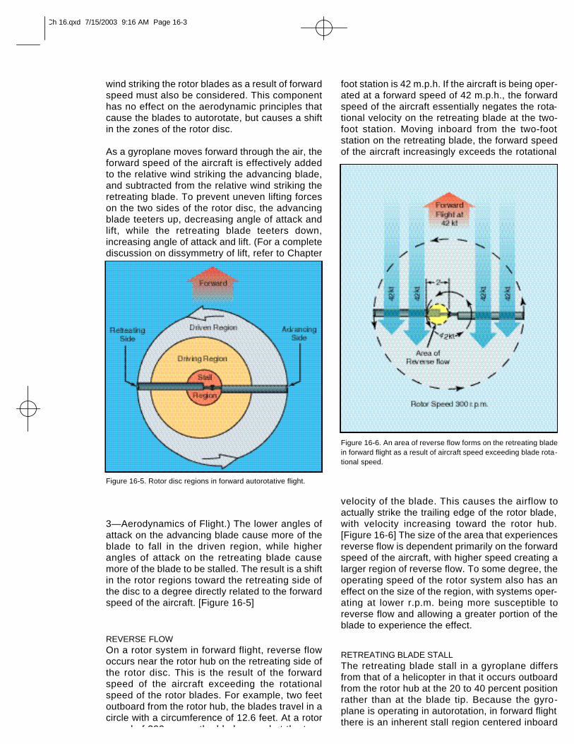
ROTOR DISC REGIONSAs with any airfoil, the lift that is created by rotorblades is perpendicular to the relative wind.Because the relative wind on rotor blades inautorotation shifts from a high angle of attackinboard to a lower angle of attack outboard, the liftgenerated has a higher forward component closerto the hub and a higher vertical component towardthe blade tips. This creates distinct regions of therotor disc that create the forces necessary forflight in autorotation. [Figure 16-4] The autorota-tive region, or driving region, creates a total aero-dynamic force with a forward component thatexceeds all rearward drag forces and keeps theblades spinning. The propeller region, or drivenregion, generates a total aerodynamic force witha higher vertical component that allows the gyro-plane to remain aloft. Near the center of the rotordisc is a stall region where the rotational compo-nent of the relative wind is so low that the result-ing angle of attack is beyond the stall limit of theairfoil. The stall region creates drag against thedirection of rotation that must be overcome by theforward acting forces generated by the drivingregion.
AUTOROTATION IN FORWARD FLIGHTAs discussed thus far, the aerodynamics ofautorotation apply to a gyroplane in a vertical
descent. Because gyroplanes are normally oper-ated in forward flight, the component of relative
Figure 16-3. Moving outboard on the rotor blade, the rotational velocity increasingly exceeds the upward component of airflow, resultingin a higher relative wind at a lower angle of attack.
Figure 16-4. The total aerodynamic force is aft of the axis of rota-tion in the driven region and forward of the axis of rotation in thedriving region. Drag is the major aerodynamic force in the stallregion. For a complete depiction of force vectors during a verticalautorotation, refer to Chapter 3—Aerodynamics of Flight(Helicopter), Figure 3-22.
Ch 16.qxd 7/15/2003 9:16 AM Page 16-2
wind striking the rotor blades as a result of forwardspeed must also be considered. This componenthas no effect on the aerodynamic principles thatcause the blades to autorotate, but causes a shiftin the zones of the rotor disc.
As a gyroplane moves forward through the air, theforward speed of the aircraft is effectively addedto the relative wind striking the advancing blade,and subtracted from the relative wind striking theretreating blade. To prevent uneven lifting forceson the two sides of the rotor disc, the advancingblade teeters up, decreasing angle of attack andlift, while the retreating blade teeters down,increasing angle of attack and lift. (For a completediscussion on dissymmetry of lift, refer to Chapter
3—Aerodynamics of Flight.) The lower angles ofattack on the advancing blade cause more of theblade to fall in the driven region, while higherangles of attack on the retreating blade causemore of the blade to be stalled. The result is a shiftin the rotor regions toward the retreating side ofthe disc to a degree directly related to the forwardspeed of the aircraft. [Figure 16-5]
REVERSE FLOWOn a rotor system in forward flight, reverse flowoccurs near the rotor hub on the retreating side ofthe rotor disc. This is the result of the forwardspeed of the aircraft exceeding the rotationalspeed of the rotor blades. For example, two feetoutboard from the rotor hub, the blades travel in acircle with a circumference of 12.6 feet. At a rotorspeed of 300 r.p.m., the blade speed at the two-
foot station is 42 m.p.h. If the aircraft is being oper-ated at a forward speed of 42 m.p.h., the forwardspeed of the aircraft essentially negates the rota-tional velocity on the retreating blade at the two-foot station. Moving inboard from the two-footstation on the retreating blade, the forward speedof the aircraft increasingly exceeds the rotational
velocity of the blade. This causes the airflow toactually strike the trailing edge of the rotor blade,with velocity increasing toward the rotor hub.[Figure 16-6] The size of the area that experiencesreverse flow is dependent primarily on the forwardspeed of the aircraft, with higher speed creating alarger region of reverse flow. To some degree, theoperating speed of the rotor system also has aneffect on the size of the region, with systems oper-ating at lower r.p.m. being more susceptible toreverse flow and allowing a greater portion of theblade to experience the effect.
RETREATING BLADE STALLThe retreating blade stall in a gyroplane differsfrom that of a helicopter in that it occurs outboardfrom the rotor hub at the 20 to 40 percent positionrather than at the blade tip. Because the gyro-plane is operating in autorotation, in forward flightthere is an inherent stall region centered inboard
Figure 16-5. Rotor disc regions in forward autorotative flight.
Figure 16-6. An area of reverse flow forms on the retreating bladein forward flight as a result of aircraft speed exceeding blade rota-tional speed.
Ch 16.qxd 7/15/2003 9:16 AM Page 16-3
given airfoil produces the most lift for the leastdrag. However, the airfoil of a rotor blade does notoperate at this efficient angle throughout the manychanges that occur in each revolution. Also, therotor system must remain in the autorotative (low)pitch range to continue turning in order to gener-ate lift.
Some gyroplanes use small wings for creating liftwhen operating at higher cruise speeds. The liftprovided by the wings can either supplement orentirely replace rotor lift while creating much lessinduced drag.
ROTOR DRAGTotal rotor drag is the summation of all the dragforces acting on the airfoil at each blade position.Each blade position contributes to the total dragaccording to the speed and angle of the airfoil atthat position. As the rotor blades turn, rapidchanges occur on the airfoils depending on posi-tion, rotor speed, and aircraft speed. A change inthe angle of attack of the rotor disc can effect arapid and substantial change in total rotor drag.
Rotor drag can be divided into components ofinduced drag and profile drag. The induced dragis a product of lift, while the profile drag is a func-tion of rotor r.p.m. Because induced drag is aresult of the rotor providing lift, profile drag can beconsidered the drag of the rotor when it is not pro-ducing lift. To visualize profile drag, consider thedrag that must be overcome to prerotate the rotor
on the retreating blade. [Refer to figure 16-5] Asforward speed increases, the angle of attack onthe retreating blade increases to prevent dissym-metry of lift and the stall region moves further outboard on the retreating blade. Because thestalled portion of the rotor disc is inboard ratherthan near the tip, as with a helicopter, less force iscreated about the aircraft center of gravity. Theresult is that you may feel a slight increase invibration, but you would not experience a largepitch or roll tendency.
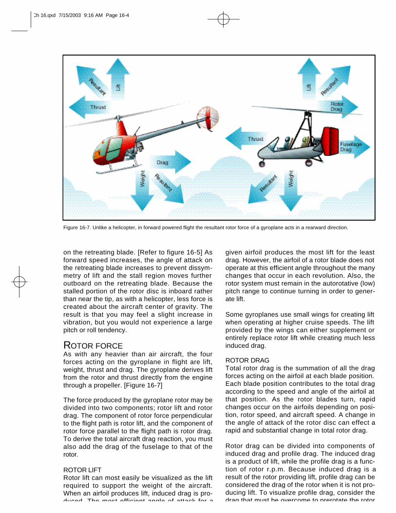
ROTOR FORCEAs with any heavier than air aircraft, the fourforces acting on the gyroplane in flight are lift,weight, thrust and drag. The gyroplane derives liftfrom the rotor and thrust directly from the enginethrough a propeller. [Figure 16-7]
The force produced by the gyroplane rotor may bedivided into two components; rotor lift and rotordrag. The component of rotor force perpendicularto the flight path is rotor lift, and the component ofrotor force parallel to the flight path is rotor drag.To derive the total aircraft drag reaction, you mustalso add the drag of the fuselage to that of therotor.
ROTOR LIFTRotor lift can most easily be visualized as the liftrequired to support the weight of the aircraft.When an airfoil produces lift, induced drag is pro-duced. The most efficient angle of attack for a
Figure 16-7. Unlike a helicopter, in forward powered flight the resultant rotor force of a gyroplane acts in a rearward direction.
Ch 16.qxd 7/15/2003 9:16 AM Page 16-4
system to flight r.p.m. while the blades are pro-ducing no lift. This can be achieved with a rotorsystem having a symmetrical airfoil and a pitchchange capability by setting the blades to a 0°angle of attack. A rotor system with an asymmetri-cal airfoil and a built in pitch angle, which includesmost amateur-built teeter-head rotor systems,cannot be prerotated without having to overcomethe induced drag created as well.
THRUSTThrust in a gyroplane is defined as the componentof total propeller force parallel to the relative wind.As with any force applied to an aircraft, thrust actsaround the center of gravity. Based upon wherethe thrust is applied in relation to the aircraft cen-ter of gravity, a relatively small component may beperpendicular to the relative wind and can be con-sidered to be additive to lift or weight.
Figure 16-8. Engine torque applied to the propeller has an equaland opposite reaction on the fuselage, deflecting it a few degreesout of the vertical plane in flight.
Pendular Action—The lateral orlongitudinal oscillation of thefuselage due to it being sus-pended from the rotor system. Itis similar to the action of a pen-dulum. Pendular action is furtherdiscussed in Chapter 3—Aerodynamics of Flight.
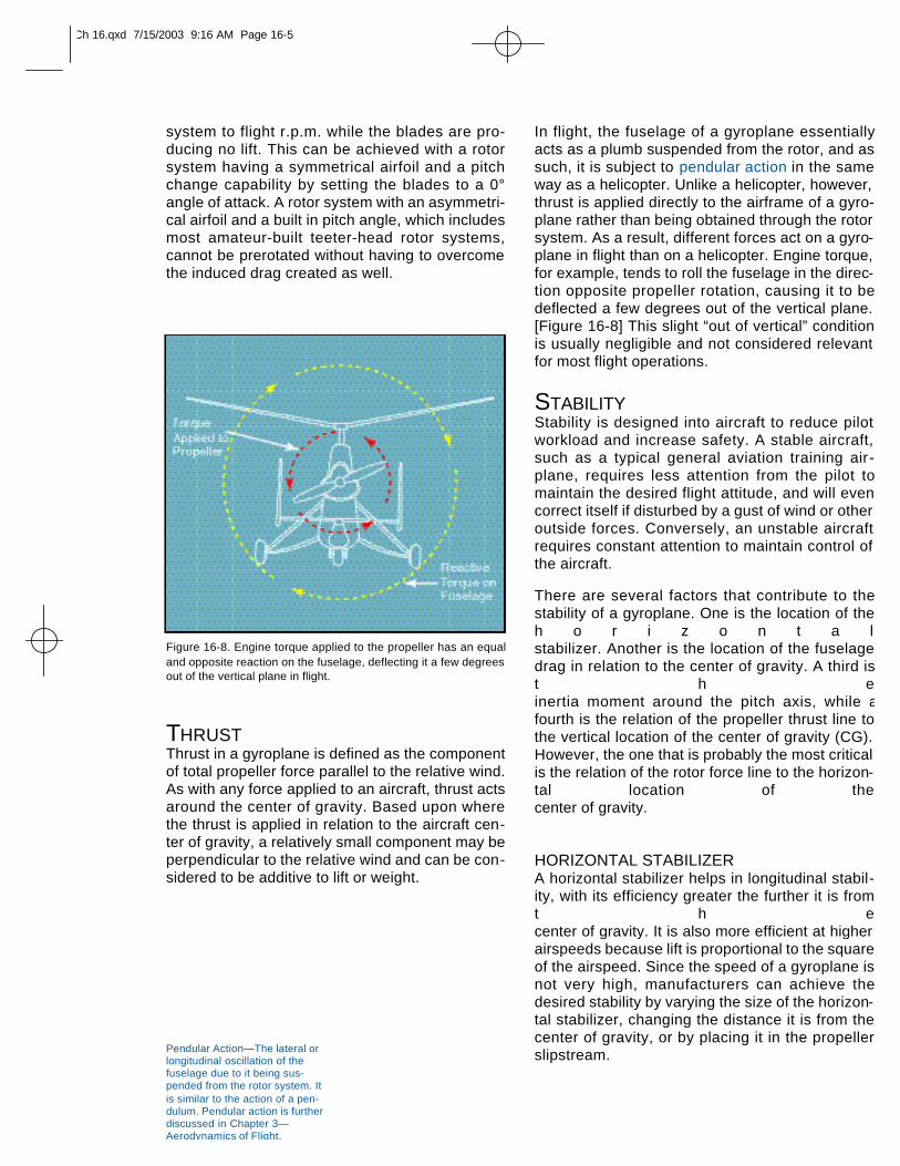
In flight, the fuselage of a gyroplane essentiallyacts as a plumb suspended from the rotor, and assuch, it is subject to pendular action in the sameway as a helicopter. Unlike a helicopter, however,thrust is applied directly to the airframe of a gyro-plane rather than being obtained through the rotorsystem. As a result, different forces act on a gyro-plane in flight than on a helicopter. Engine torque,for example, tends to roll the fuselage in the direc-tion opposite propeller rotation, causing it to bedeflected a few degrees out of the vertical plane.[Figure 16-8] This slight “out of vertical” conditionis usually negligible and not considered relevantfor most flight operations.
STABILITYStability is designed into aircraft to reduce pilotworkload and increase safety. A stable aircraft,such as a typical general aviation training air-plane, requires less attention from the pilot tomaintain the desired flight attitude, and will evencorrect itself if disturbed by a gust of wind or otheroutside forces. Conversely, an unstable aircraftrequires constant attention to maintain control ofthe aircraft.
There are several factors that contribute to thestability of a gyroplane. One is the location of theh o r i z o n t a lstabilizer. Another is the location of the fuselagedrag in relation to the center of gravity. A third ist h einertia moment around the pitch axis, while afourth is the relation of the propeller thrust line tothe vertical location of the center of gravity (CG).However, the one that is probably the most criticalis the relation of the rotor force line to the horizon-tal location of the center of gravity.
HORIZONTAL STABILIZERA horizontal stabilizer helps in longitudinal stabil-ity, with its efficiency greater the further it is fromt h ecenter of gravity. It is also more efficient at higher airspeeds because lift is proportional to the squareof the airspeed. Since the speed of a gyroplane isnot very high, manufacturers can achieve thedesired stability by varying the size of the horizon-tal stabilizer, changing the distance it is from thecenter of gravity, or by placing it in the propellerslipstream.
Ch 16.qxd 7/15/2003 9:16 AM Page 16-5
FUSELAGE DRAG(CENTER OF PRESSURE)If the location, where the fuselage drag or centerof pressure forces are concentrated, is behindthe CG, the gyroplane is considered more stable.This is especially true of yaw stability around thevertical axis. However, to achieve this condition,there must be a sufficient vertical tail surface. Inaddition, the gyroplane needs to have a bal-anced longitudinal center of pressure so there issufficient cyclic movement toprevent the nose from tucking under or lifting, aspressure builds on the frontal area of the gyro-plane as airspeed increases.
PITCH INERTIAWithout changing the overall weight and center ofgravity of a gyroplane, the further weights areplaced from the CG, the more stable the gyro-plane. For example, if the pilot's seat could bemoved forward from the CG, and the enginemoved aft an amount, which keeps the center ofgravity in the same location, the gyroplanebecomes more stable. A tightrope walker appliesthis same principle when he uses a long pole tobalance himself.
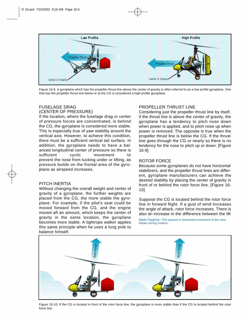
PROPELLER THRUST LINEConsidering just the propeller thrust line by itself,if the thrust line is above the center of gravity, thegyroplane has a tendency to pitch nose downwhen power is applied, and to pitch nose up whenpower is removed. The opposite is true when thepropeller thrust line is below the CG. If the thrustline goes through the CG or nearly so there is notendency for the nose to pitch up or down. [Figure16-9]
ROTOR FORCEBecause some gyroplanes do not have horizontalstabilizers, and the propeller thrust lines are differ-ent, gyroplane manufacturers can achieve thedesired stability by placing the center of gravity infront of or behind the rotor force line. [Figure 16-10]
Suppose the CG is located behind the rotor forceline in forward flight. If a gust of wind increasesthe angle of attack, rotor force increases. There isalso an increase in the difference between the lift
Figure 16-9. A gyroplane which has the propeller thrust line above the center of gravity is often referred to as a low profile gyroplane. Onethat has the propeller thrust line below or at the CG is considered a high profile gyroplane.
Figure 16-10. If the CG is located in front of the rotor force line, the gyroplane is more stable than if the CG is located behind the rotorforce line.
Blade Flapping—The upward or downward movement of the rotor-blades during rotation.
Ch 16.qxd 7/15/2003 9:16 AM Page 16-6
Due to rudimentary flight control systems, early gyro-planes suffered from limited maneuverability. As tech-nology improved, greater control of the rotorsystem and more effective control surfaces weredeveloped. The modern gyroplane, while continu-ing to maintain an element of simplicity, nowenjoys a high degree of maneuverability as aresult of these improvements.
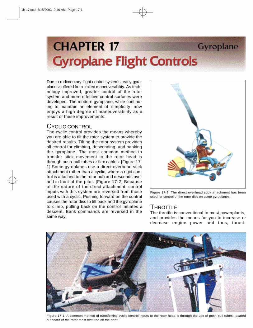
CYCLIC CONTROLThe cyclic control provides the means wherebyyou are able to tilt the rotor system to provide thedesired results. Tilting the rotor system providesall control for climbing, descending, and bankingthe gyroplane. The most common method totransfer stick movement to the rotor head isthrough push-pull tubes or flex cables. [Figure 17-1] Some gyroplanes use a direct overhead stickattachment rather than a cyclic, where a rigid con-trol is attached to the rotor hub and descends overand in front of the pilot. [Figure 17-2] Becauseof the nature of the direct attachment, controlinputs with this system are reversed from thoseused with a cyclic. Pushing forward on the controlcauses the rotor disc to tilt back and the gyroplaneto climb, pulling back on the control initiates adescent. Bank commands are reversed in thesame way.
THROTTLEThe throttle is conventional to most powerplants,and provides the means for you to increase ordecrease engine power and thus, thrust.
Figure 17-1. A common method of transferring cyclic control inputs to the rotor head is through the use of push-pull tubes, locatedoutboard of the rotor mast pictured on the right.
Figure 17-2. The direct overhead stick attachment has beenused for control of the rotor disc on some gyroplanes.
Ch 17.qxd 7/15/2003 9:16 AM Page 17-1
Depending on how the control is designed, con-trol movement may or may not be proportionalto engine power. With many gyroplane throttles,50 percent of the control travel may equate to 80or 90 percent of available power. This varyingdegree of sensitivity makes it necessary for you tobecome familiar with the unique throttle characteristics and engine responses for a particu-lar gyroplane.
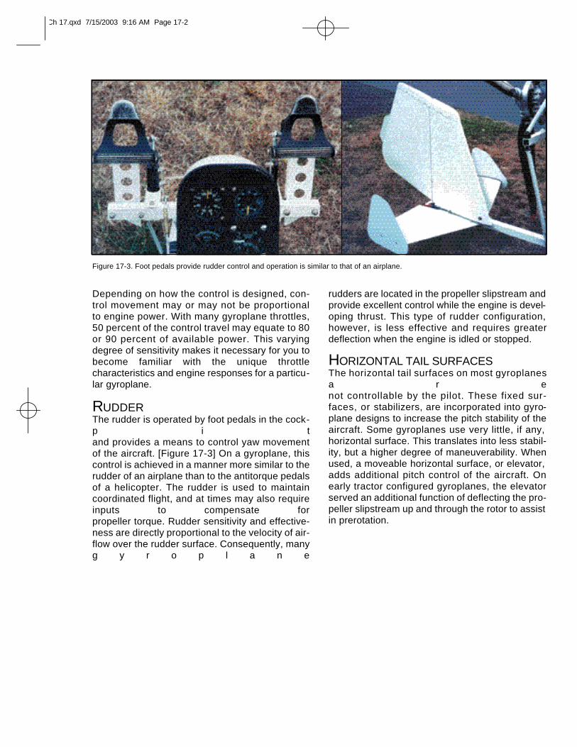
RUDDERThe rudder is operated by foot pedals in the cock-p i tand provides a means to control yaw movementof the aircraft. [Figure 17-3] On a gyroplane, thiscontrol is achieved in a manner more similar to therudder of an airplane than to the antitorque pedalsof a helicopter. The rudder is used to maintaincoordinated flight, and at times may also requireinputs to compensate for propeller torque. Rudder sensitivity and effective-ness are directly proportional to the velocity of air-flow over the rudder surface. Consequently, manyg y r o p l a n e
rudders are located in the propeller slipstream and provide excellent control while the engine is devel-oping thrust. This type of rudder configuration,however, is less effective and requires greaterdeflection when the engine is idled or stopped.
HORIZONTAL TAIL SURFACESThe horizontal tail surfaces on most gyroplanesa r enot controllable by the pilot. These fixed sur-faces, or stabilizers, are incorporated into gyro-plane designs to increase the pitch stability of theaircraft. Some gyroplanes use very little, if any,horizontal surface. This translates into less stabil-ity, but a higher degree of maneuverability. Whenused, a moveable horizontal surface, or elevator,adds additional pitch control of the aircraft. Onearly tractor configured gyroplanes, the elevatorserved an additional function of deflecting the pro-peller slipstream up and through the rotor to assistin prerotation.
Figure 17-3. Foot pedals provide rudder control and operation is similar to that of an airplane.
Ch 17.qxd 7/15/2003 9:16 AM Page 17-2
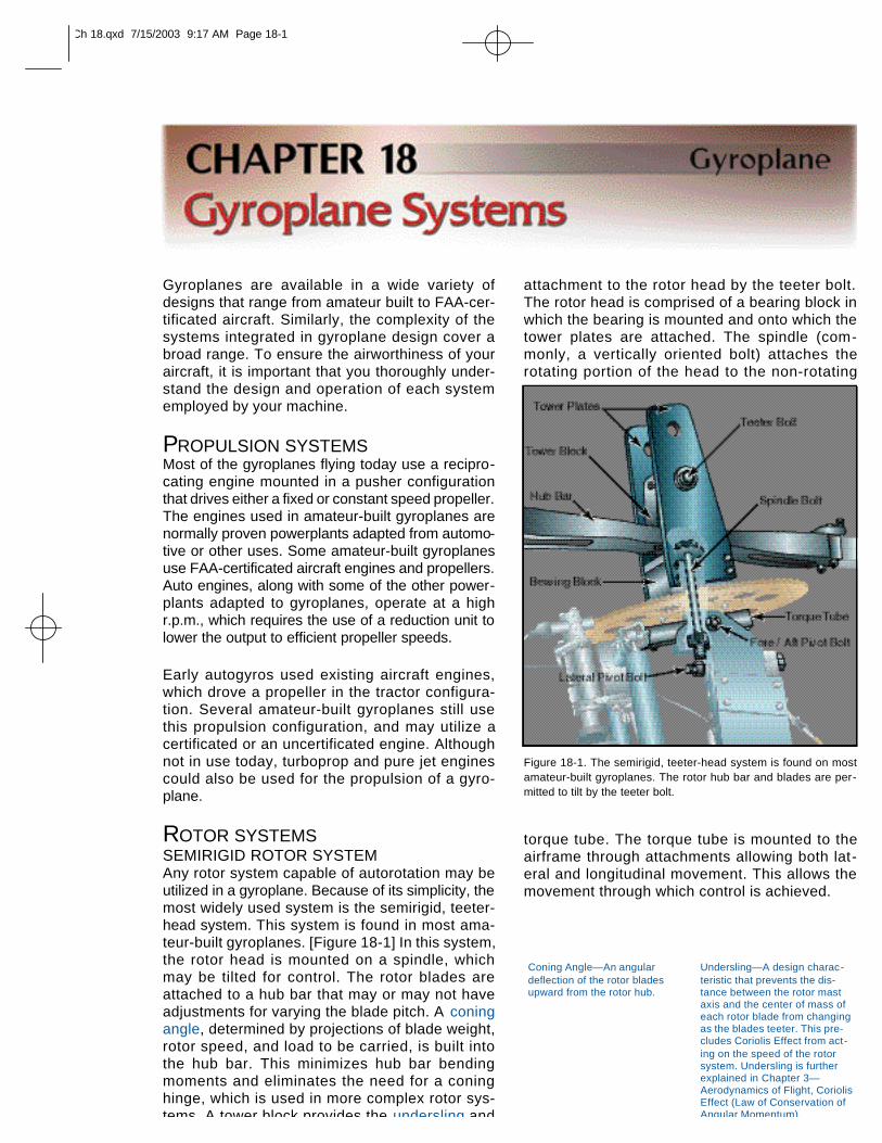
attachment to the rotor head by the teeter bolt.The rotor head is comprised of a bearing block inwhich the bearing is mounted and onto which thetower plates are attached. The spindle (com-monly, a vertically oriented bolt) attaches therotating portion of the head to the non-rotating
torque tube. The torque tube is mounted to theairframe through attachments allowing both lat-eral and longitudinal movement. This allows themovement through which control is achieved.
Coning Angle—An angulardeflection of the rotor bladesupward from the rotor hub.
Undersling—A design charac-teristic that prevents the dis-tance between the rotor mastaxis and the center of mass ofeach rotor blade from changingas the blades teeter. This pre-cludes Coriolis Effect from act-ing on the speed of the rotorsystem. Undersling is furtherexplained in Chapter 3—Aerodynamics of Flight, CoriolisEffect (Law of Conservation ofAngular Momentum).
Gyroplanes are available in a wide variety ofdesigns that range from amateur built to FAA-cer-tificated aircraft. Similarly, the complexity of thesystems integrated in gyroplane design cover abroad range. To ensure the airworthiness of youraircraft, it is important that you thoroughly under-stand the design and operation of each systememployed by your machine.
PROPULSION SYSTEMSMost of the gyroplanes flying today use a recipro-cating engine mounted in a pusher configurationthat drives either a fixed or constant speed propeller.The engines used in amateur-built gyroplanes arenormally proven powerplants adapted from automo-tive or other uses. Some amateur-built gyroplanesuse FAA-certificated aircraft engines and propellers.Auto engines, along with some of the other power-plants adapted to gyroplanes, operate at a highr.p.m., which requires the use of a reduction unit tolower the output to efficient propeller speeds.
Early autogyros used existing aircraft engines,which drove a propeller in the tractor configura-tion. Several amateur-built gyroplanes still usethis propulsion configuration, and may utilize acertificated or an uncertificated engine. Althoughnot in use today, turboprop and pure jet enginescould also be used for the propulsion of a gyro-plane.
ROTOR SYSTEMSSEMIRIGID ROTOR SYSTEMAny rotor system capable of autorotation may beutilized in a gyroplane. Because of its simplicity, themost widely used system is the semirigid, teeter-head system. This system is found in most ama-teur-built gyroplanes. [Figure 18-1] In this system,the rotor head is mounted on a spindle, whichmay be tilted for control. The rotor blades areattached to a hub bar that may or may not haveadjustments for varying the blade pitch. A coningangle, determined by projections of blade weight,rotor speed, and load to be carried, is built intothe hub bar. This minimizes hub bar bendingmoments and eliminates the need for a coninghinge, which is used in more complex rotor sys-tems. A tower block provides the undersling and
Figure 18-1. The semirigid, teeter-head system is found on mostamateur-built gyroplanes. The rotor hub bar and blades are per-mitted to tilt by the teeter bolt.
Ch 18.qxd 7/15/2003 9:17 AM Page 18-1
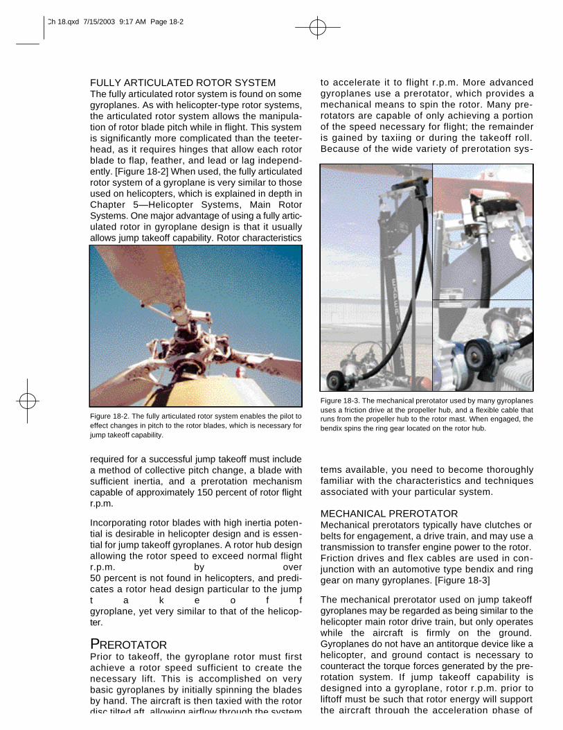
FULLY ARTICULATED ROTOR SYSTEM The fully articulated rotor system is found on somegyroplanes. As with helicopter-type rotor systems,the articulated rotor system allows the manipula-tion of rotor blade pitch while in flight. This systemis significantly more complicated than the teeter-head, as it requires hinges that allow each rotorblade to flap, feather, and lead or lag independ-ently. [Figure 18-2] When used, the fully articulatedrotor system of a gyroplane is very similar to thoseused on helicopters, which is explained in depth inChapter 5—Helicopter Systems, Main RotorSystems. One major advantage of using a fully artic-ulated rotor in gyroplane design is that it usuallyallows jump takeoff capability. Rotor characteristics
required for a successful jump takeoff must includea method of collective pitch change, a blade withsufficient inertia, and a prerotation mechanismcapable of approximately 150 percent of rotor flightr.p.m.
Incorporating rotor blades with high inertia poten-tial is desirable in helicopter design and is essen-tial for jump takeoff gyroplanes. A rotor hub designallowing the rotor speed to exceed normal flightr.p.m. by over 50 percent is not found in helicopters, and predi-cates a rotor head design particular to the jumpt a k e o f fgyroplane, yet very similar to that of the helicop-ter.
PREROTATORPrior to takeoff, the gyroplane rotor must firstachieve a rotor speed sufficient to create thenecessary lift. This is accomplished on verybasic gyroplanes by initially spinning the bladesby hand. The aircraft is then taxied with the rotordisc tilted aft, allowing airflow through the system
to accelerate it to flight r.p.m. More advancedgyroplanes use a prerotator, which provides amechanical means to spin the rotor. Many pre-rotators are capable of only achieving a portionof the speed necessary for flight; the remainderis gained by taxiing or during the takeoff roll.Because of the wide variety of prerotation sys-
tems available, you need to become thoroughlyfamiliar with the characteristics and techniquesassociated with your particular system.
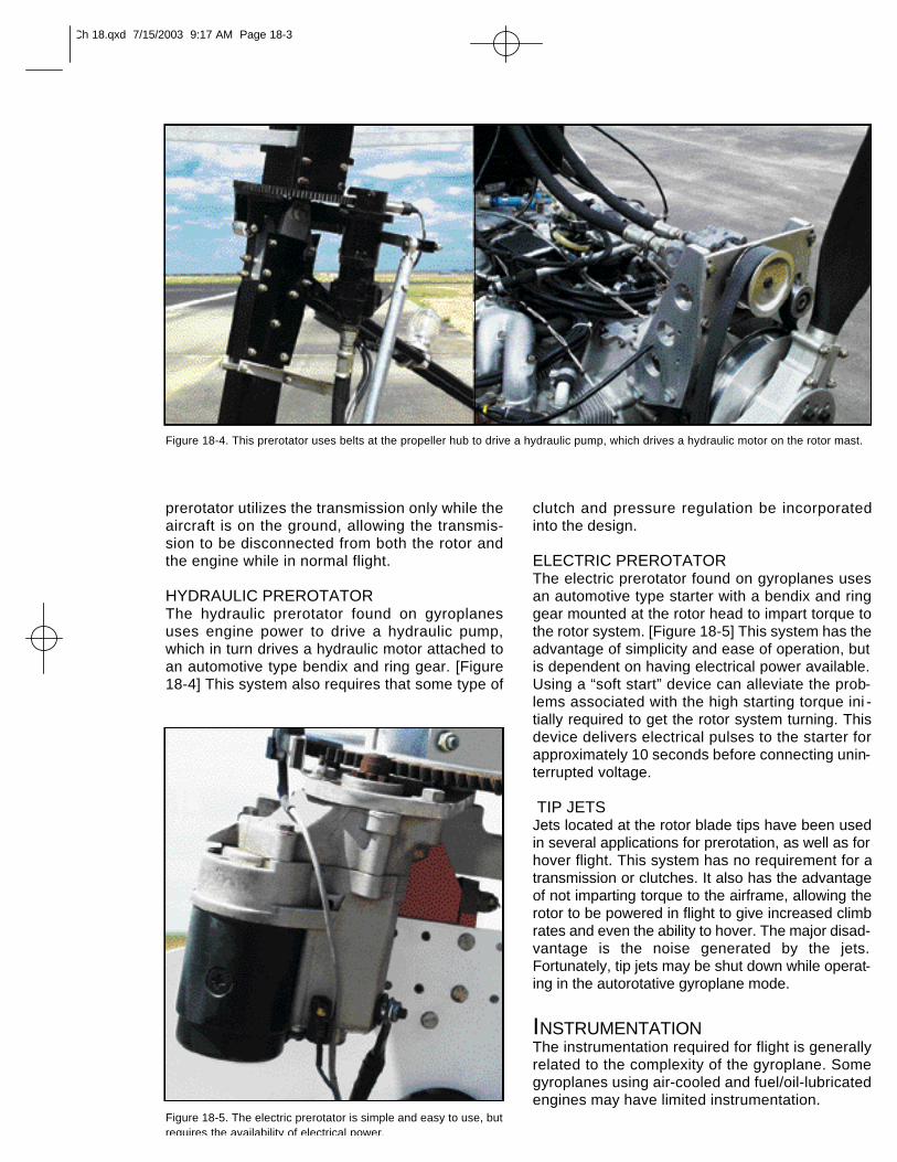
MECHANICAL PREROTATORMechanical prerotators typically have clutches orbelts for engagement, a drive train, and may use atransmission to transfer engine power to the rotor.Friction drives and flex cables are used in con-junction with an automotive type bendix and ringgear on many gyroplanes. [Figure 18-3]
The mechanical prerotator used on jump takeoffgyroplanes may be regarded as being similar to thehelicopter main rotor drive train, but only operateswhile the aircraft is firmly on the ground.Gyroplanes do not have an antitorque device like ahelicopter, and ground contact is necessary tocounteract the torque forces generated by the pre-rotation system. If jump takeoff capability isdesigned into a gyroplane, rotor r.p.m. prior toliftoff must be such that rotor energy will supportthe aircraft through the acceleration phase of
Figure 18-2. The fully articulated rotor system enables the pilot toeffect changes in pitch to the rotor blades, which is necessary forjump takeoff capability.
Figure 18-3. The mechanical prerotator used by many gyroplanesuses a friction drive at the propeller hub, and a flexible cable thatruns from the propeller hub to the rotor mast. When engaged, thebendix spins the ring gear located on the rotor hub.
Ch 18.qxd 7/15/2003 9:17 AM Page 18-2
prerotator utilizes the transmission only while theaircraft is on the ground, allowing the transmis-sion to be disconnected from both the rotor andthe engine while in normal flight.
HYDRAULIC PREROTATORThe hydraulic prerotator found on gyroplanesuses engine power to drive a hydraulic pump,which in turn drives a hydraulic motor attached toan automotive type bendix and ring gear. [Figure18-4] This system also requires that some type of
clutch and pressure regulation be incorporatedinto the design.
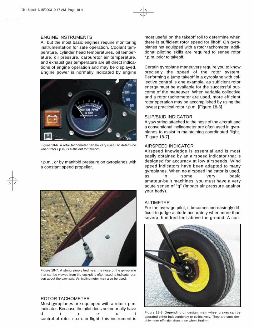
ELECTRIC PREROTATORThe electric prerotator found on gyroplanes usesan automotive type starter with a bendix and ringgear mounted at the rotor head to impart torque tothe rotor system. [Figure 18-5] This system has theadvantage of simplicity and ease of operation, butis dependent on having electrical power available.Using a “soft start” device can alleviate the prob-lems associated with the high starting torque ini -tially required to get the rotor system turning. Thisdevice delivers electrical pulses to the starter forapproximately 10 seconds before connecting unin-terrupted voltage.
TIP JETSJets located at the rotor blade tips have been usedin several applications for prerotation, as well as forhover flight. This system has no requirement for atransmission or clutches. It also has the advantageof not imparting torque to the airframe, allowing therotor to be powered in flight to give increased climbrates and even the ability to hover. The major disad-vantage is the noise generated by the jets.Fortunately, tip jets may be shut down while operat-ing in the autorotative gyroplane mode.
INSTRUMENTATIONThe instrumentation required for flight is generallyrelated to the complexity of the gyroplane. Somegyroplanes using air-cooled and fuel/oil-lubricatedengines may have limited instrumentation.
Figure 18-4. This prerotator uses belts at the propeller hub to drive a hydraulic pump, which drives a hydraulic motor on the rotor mast.
Figure 18-5. The electric prerotator is simple and easy to use, butrequires the availability of electrical power.
Ch 18.qxd 7/15/2003 9:17 AM Page 18-3
ENGINE INSTRUMENTSAll but the most basic engines require monitoringinstrumentation for safe operation. Coolant tem-perature, cylinder head temperatures, oil temper-ature, oil pressure, carburetor air temperature,and exhaust gas temperature are all direct indica-tions of engine operation and may be displayed.Engine power is normally indicated by engine
r.p.m., or by manifold pressure on gyroplanes witha constant speed propeller.
ROTOR TACHOMETERMost gyroplanes are equipped with a rotor r.p.m.indicator. Because the pilot does not normally haved i r e c tcontrol of rotor r.p.m. in flight, this instrument is
most useful on the takeoff roll to determine whenthere is sufficient rotor speed for liftoff. On gyro-planes not equipped with a rotor tachometer, addi-tional piloting skills are required to sense rotorr.p.m. prior to takeoff.
Certain gyroplane maneuvers require you to knowprecisely the speed of the rotor system.Performing a jump takeoff in a gyroplane with col-lective control is one example, as sufficient rotorenergy must be available for the successful out-come of the maneuver. When variable collectiveand a rotor tachometer are used, more efficientrotor operation may be accomplished by using thelowest practical rotor r.p.m. [Figure 18-6]
SLIP/SKID INDICATORA yaw string attached to the nose of the aircraft anda conventional inclinometer are often used in gyro-planes to assist in maintaining coordinated flight.[Figure 18-7]
AIRSPEED INDICATORAirspeed knowledge is essential and is mosteasily obtained by an airspeed indicator that isdesigned for accuracy at low airspeeds. Windspeed indicators have been adapted to manygyroplanes. When no airspeed indicator is used,as in some very basic amateur-built machines, you must have a veryacute sense of “q” (impact air pressure againstyour body).
ALTIMETERFor the average pilot, it becomes increasingly dif-ficult to judge altitude accurately when more thanseveral hundred feet above the ground. A con-
Figure 18-6. A rotor tachometer can be very useful to determinewhen rotor r.p.m. is sufficient for takeoff.
Figure 18-7. A string simply tied near the nose of the gyroplanethat can be viewed from the cockpit is often used to indicate rota-tion about the yaw axis. An inclinometer may also be used.
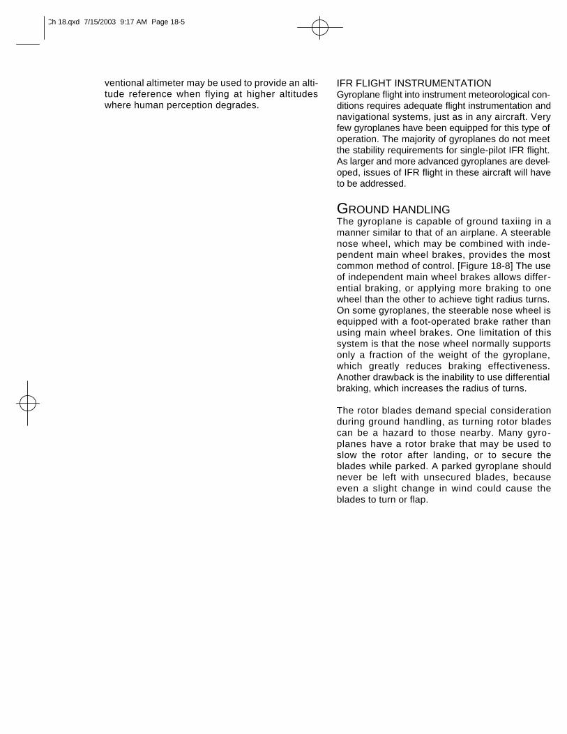
Figure 18-8. Depending on design, main wheel brakes can beoperated either independently or collectively. They are consider-ably more effective than nose wheel brakes.
Ch 18.qxd 7/15/2003 9:17 AM Page 18-4
ventional altimeter may be used to provide an alti-tude reference when flying at higher altitudeswhere human perception degrades.
IFR FLIGHT INSTRUMENTATIONGyroplane flight into instrument meteorological con-ditions requires adequate flight instrumentation andnavigational systems, just as in any aircraft. Veryfew gyroplanes have been equipped for this type ofoperation. The majority of gyroplanes do not meetthe stability requirements for single-pilot IFR flight.As larger and more advanced gyroplanes are devel-oped, issues of IFR flight in these aircraft will haveto be addressed.
GROUND HANDLINGThe gyroplane is capable of ground taxiing in amanner similar to that of an airplane. A steerablenose wheel, which may be combined with inde-pendent main wheel brakes, provides the mostcommon method of control. [Figure 18-8] The useof independent main wheel brakes allows differ-ential braking, or applying more braking to onewheel than the other to achieve tight radius turns.On some gyroplanes, the steerable nose wheel isequipped with a foot-operated brake rather thanusing main wheel brakes. One limitation of thissystem is that the nose wheel normally supportsonly a fraction of the weight of the gyroplane,which greatly reduces braking effectiveness.Another drawback is the inability to use differentialbraking, which increases the radius of turns.
The rotor blades demand special considerationduring ground handling, as turning rotor bladescan be a hazard to those nearby. Many gyro-planes have a rotor brake that may be used toslow the rotor after landing, or to secure theblades while parked. A parked gyroplane shouldnever be left with unsecured blades, becauseeven a slight change in wind could cause theblades to turn or flap.
Ch 18.qxd 7/15/2003 9:17 AM Page 18-5
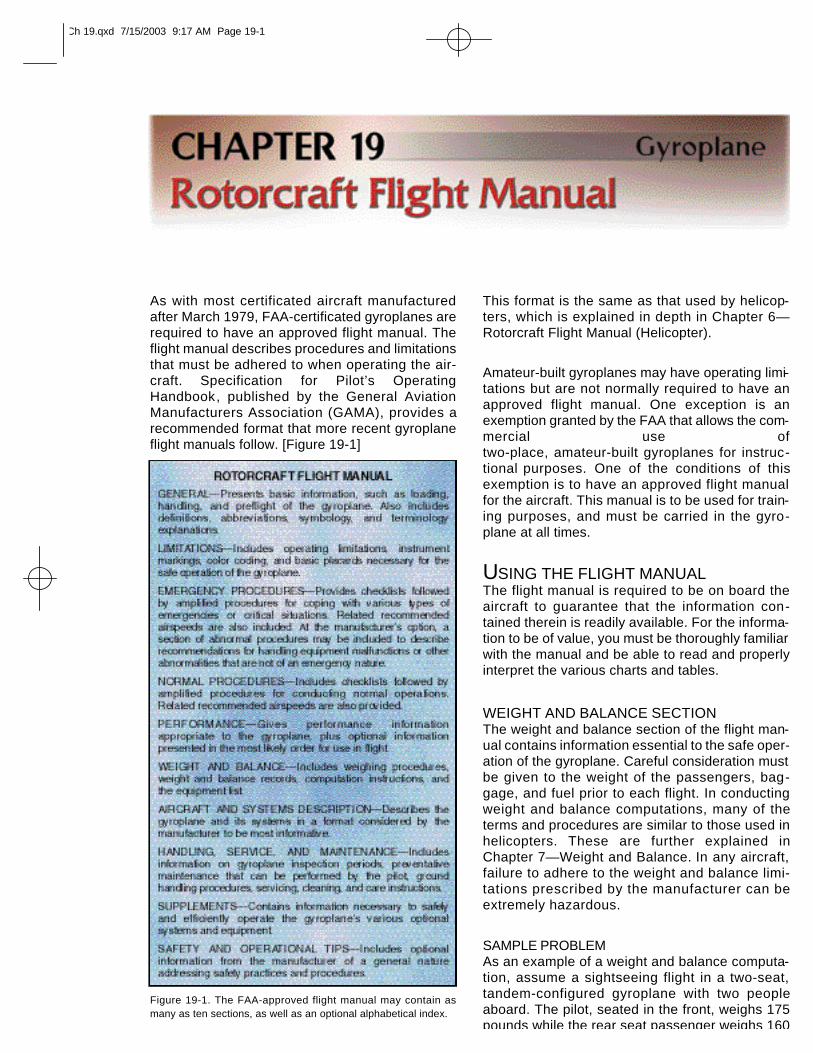
As with most certificated aircraft manufacturedafter March 1979, FAA-certificated gyroplanes arerequired to have an approved flight manual. Theflight manual describes procedures and limitationsthat must be adhered to when operating the air-craft. Specification for Pilot’s OperatingHandbook, published by the General AviationManufacturers Association (GAMA), provides arecommended format that more recent gyroplaneflight manuals follow. [Figure 19-1]
This format is the same as that used by helicop-ters, which is explained in depth in Chapter 6—Rotorcraft Flight Manual (Helicopter).
Amateur-built gyroplanes may have operating limi-tations but are not normally required to have anapproved flight manual. One exception is anexemption granted by the FAA that allows the com-mercial use of two-place, amateur-built gyroplanes for instruc-tional purposes. One of the conditions of thisexemption is to have an approved flight manualfor the aircraft. This manual is to be used for train-ing purposes, and must be carried in the gyro-plane at all times.
USING THE FLIGHT MANUALThe flight manual is required to be on board theaircraft to guarantee that the information con-tained therein is readily available. For the informa-tion to be of value, you must be thoroughly familiarwith the manual and be able to read and properlyinterpret the various charts and tables.
WEIGHT AND BALANCE SECTIONThe weight and balance section of the flight man-ual contains information essential to the safe oper-ation of the gyroplane. Careful consideration mustbe given to the weight of the passengers, bag-gage, and fuel prior to each flight. In conductingweight and balance computations, many of theterms and procedures are similar to those used inhelicopters. These are further explained inChapter 7—Weight and Balance. In any aircraft,failure to adhere to the weight and balance limi-tations prescribed by the manufacturer can beextremely hazardous.
SAMPLE PROBLEMAs an example of a weight and balance computa-tion, assume a sightseeing flight in a two-seat,tandem-configured gyroplane with two peopleaboard. The pilot, seated in the front, weighs 175pounds while the rear seat passenger weighs 160
Figure 19-1. The FAA-approved flight manual may contain asmany as ten sections, as well as an optional alphabetical index.
Ch 19.qxd 7/15/2003 9:17 AM Page 19-1
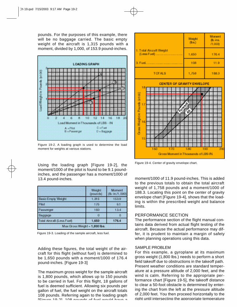
pounds. For the purposes of this example, therewill be no baggage carried. The basic emptyweight of the aircraft is 1,315 pounds with amoment, divided by 1,000, of 153.9 pound-inches.
Using the loading graph [Figure 19-2], themoment/1000 of the pilot is found to be 9.1 pound-inches, and the passenger has a moment/1000 of13.4 pound-inches.
Adding these figures, the total weight of the air-craft for this flight (without fuel) is determined tobe 1,650 pounds with a moment/1000 of 176.4pound-inches. [Figure 19-3]
The maximum gross weight for the sample aircraftis 1,800 pounds, which allows up to 150 poundsto be carried in fuel. For this flight, 18 gallons offuel is deemed sufficient. Allowing six pounds pergallon of fuel, the fuel weight on the aircraft totals108 pounds. Referring again to the loading graph[Figure 19-2], 108 pounds of fuel would have a
moment/1000 of 11.9 pound-inches. This is addedto the previous totals to obtain the total aircraftweight of 1,758 pounds and a moment/1000 of188.3. Locating this point on the center of gravityenvelope chart [Figure 19-4], shows that the load-ing is within the prescribed weight and balancelimits.
PERFORMANCE SECTIONThe performance section of the flight manual con-tains data derived from actual flight testing of theaircraft. Because the actual performance may dif-fer, it is prudent to maintain a margin of safetywhen planning operations using this data.
SAMPLE PROBLEMFor this example, a gyroplane at its maximumgross weight (1,800 lbs.) needs to perform a shortfield takeoff due to obstructions in the takeoff path.Present weather conditions are standard temper-ature at a pressure altitude of 2,000 feet, and thewind is calm. Referring to the appropriate per-formance chart [Figure 19-5], the takeoff distanceto clear a 50-foot obstacle is determined by enter-ing the chart from the left at the pressure altitudeof 2,000 feet. You then proceed horizontally to theright until intersecting the appropriate temperature
Figure 19-3. Loading of the sample aircraft, less fuel.
Figure 19-4. Center of gravity envelope chart.
Figure 19-2. A loading graph is used to determine the loadmoment for weights at various stations.
Ch 19.qxd 7/15/2003 9:17 AM Page 19-2
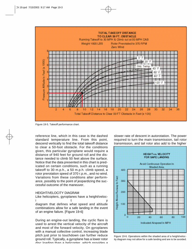
reference line, which in this case is the dashedstandard temperature line. From this point,descend vertically to find the total takeoff distanceto clear a 50-foot obstacle. For the conditionsgiven, this particular gyroplane would require adistance of 940 feet for ground roll and the dis-tance needed to climb 50 feet above the surface.Notice that the data presented in this chart is pred-icated on certain conditions, such as a runningtakeoff to 30 m.p.h., a 50 m.p.h. climb speed, arotor prerotation speed of 370 r.p.m., and no wind.Variations from these conditions alter perform-ance, possibly to the point of jeopardizing the suc-cessful outcome of the maneuver.
HEIGHT/VELOCITY DIAGRAMLike helicopters, gyroplanes have a height/veloc-i t ydiagram that defines what speed and altitudecombinations allow for a safe landing in the eventof an engine failure. [Figure 19-6]
During an engine-out landing, the cyclic flare isused to arrest the vertical velocity of the aircraftand most of the forward velocity. On gyroplaneswith a manual collective control, increasing bladepitch just prior to touchdown can further reduceground roll. Typically, a gyroplane has a lower rotordisc loading than a helicopter, which provides a
slower rate of descent in autorotation. The powerrequired to turn the main transmission, tail rotortransmission, and tail rotor also add to the higher
Figure 19-5. Takeoff performance chart.
Figure 19-6. Operations within the shaded area of a height/veloc-ity diagram may not allow for a safe landing and are to be avoided.
Ch 19.qxd 7/15/2003 9:17 AM Page 19-3
descent rate of a helicopter in autorotation as com-pared with that of a gyroplane.
EMERGENCY SECTIONBecause in-flight emergencies may not allowenough time to reference the flight manual, theemergency section should be reviewed periodi-cally to maintain familiarity with these procedures.
Many aircraft also use placards and instrumentmarkings in the cockpit, which provide importantinformation that may not be committed to mem-ory.
HANG TESTThe proper weight and balance of a gyroplanewithout a flight manual is normally determined byconducting a hang test of the aircraft. This isachieved by removing the rotor blades and sus-pending the aircraft by its teeter bolt, free fromcontact with the ground. A measurement is thentaken, either at the keel or the rotor mast, todetermine how many degrees from level the gyro-plane hangs. This number must be within therange specified by the manufacturer. For the testto reflect the true balance of the aircraft, it isimportant that it be conducted using the actualweight of the pilot and all gear normally carried inflight. Additionally, the measurement should betaken both with the fuel tank full and with it emptyto ensure that fuel burn does not affect the load-ing.
Ch 19.qxd 7/15/2003 9:17 AM Page 19-4
The diversity of gyroplane designs available todayyields a wide variety of capability and perform-ance. For safe operation, you must be thoroughlyfamiliar with the procedures and limitations foryour particular aircraft along with other factors thatmay affect the safety of your flight.
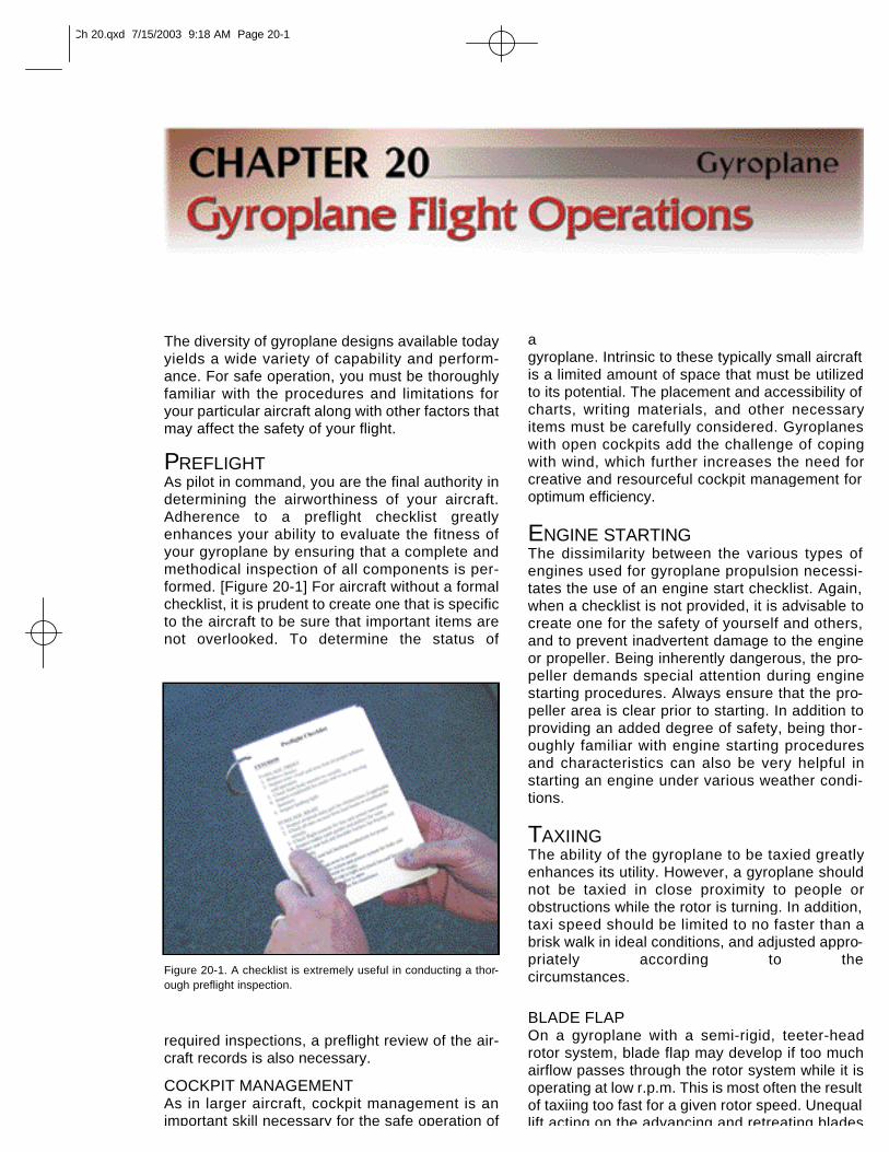
PREFLIGHTAs pilot in command, you are the final authority indetermining the airworthiness of your aircraft.Adherence to a preflight checklist greatlyenhances your ability to evaluate the fitness ofyour gyroplane by ensuring that a complete andmethodical inspection of all components is per-formed. [Figure 20-1] For aircraft without a formalchecklist, it is prudent to create one that is specificto the aircraft to be sure that important items arenot overlooked. To determine the status of
required inspections, a preflight review of the air-craft records is also necessary.
COCKPIT MANAGEMENTAs in larger aircraft, cockpit management is animportant skill necessary for the safe operation of
a gyroplane. Intrinsic to these typically small aircraftis a limited amount of space that must be utilizedto its potential. The placement and accessibility ofcharts, writing materials, and other necessaryitems must be carefully considered. Gyroplaneswith open cockpits add the challenge of copingwith wind, which further increases the need forcreative and resourceful cockpit management foroptimum efficiency.
ENGINE STARTINGThe dissimilarity between the various types ofengines used for gyroplane propulsion necessi-tates the use of an engine start checklist. Again,when a checklist is not provided, it is advisable tocreate one for the safety of yourself and others,and to prevent inadvertent damage to the engineor propeller. Being inherently dangerous, the pro-peller demands special attention during enginestarting procedures. Always ensure that the pro-peller area is clear prior to starting. In addition toproviding an added degree of safety, being thor-oughly familiar with engine starting proceduresand characteristics can also be very helpful instarting an engine under various weather condi-tions.
TAXIINGThe ability of the gyroplane to be taxied greatlyenhances its utility. However, a gyroplane shouldnot be taxied in close proximity to people orobstructions while the rotor is turning. In addition,taxi speed should be limited to no faster than abrisk walk in ideal conditions, and adjusted appro-priately according to the circumstances.
BLADE FLAPOn a gyroplane with a semi-rigid, teeter-headrotor system, blade flap may develop if too muchairflow passes through the rotor system while it isoperating at low r.p.m. This is most often the resultof taxiing too fast for a given rotor speed. Unequallift acting on the advancing and retreating blades
Figure 20-1. A checklist is extremely useful in conducting a thor-ough preflight inspection.
Ch 20.qxd 7/15/2003 9:18 AM Page 20-1
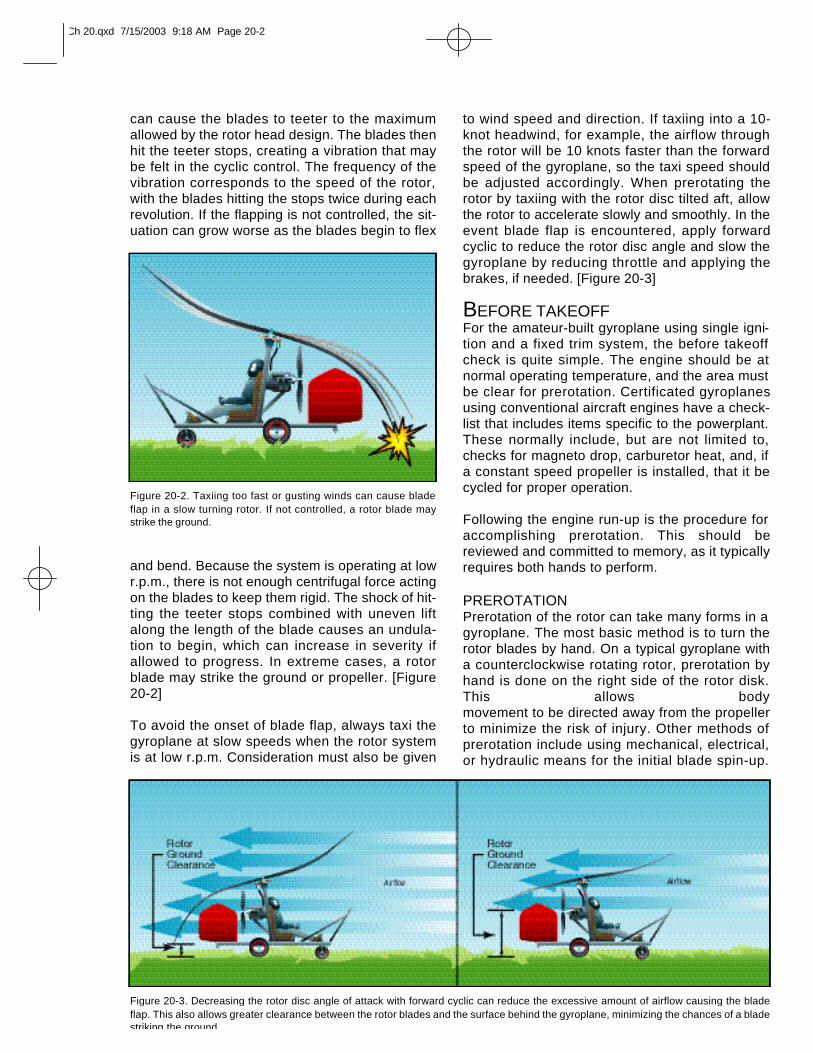
can cause the blades to teeter to the maximumallowed by the rotor head design. The blades thenhit the teeter stops, creating a vibration that maybe felt in the cyclic control. The frequency of thevibration corresponds to the speed of the rotor,with the blades hitting the stops twice during eachrevolution. If the flapping is not controlled, the sit-uation can grow worse as the blades begin to flex
and bend. Because the system is operating at lowr.p.m., there is not enough centrifugal force actingon the blades to keep them rigid. The shock of hit-ting the teeter stops combined with uneven liftalong the length of the blade causes an undula-tion to begin, which can increase in severity ifallowed to progress. In extreme cases, a rotorblade may strike the ground or propeller. [Figure20-2]
To avoid the onset of blade flap, always taxi thegyroplane at slow speeds when the rotor systemis at low r.p.m. Consideration must also be given
to wind speed and direction. If taxiing into a 10-knot headwind, for example, the airflow throughthe rotor will be 10 knots faster than the forwardspeed of the gyroplane, so the taxi speed shouldbe adjusted accordingly. When prerotating therotor by taxiing with the rotor disc tilted aft, allowthe rotor to accelerate slowly and smoothly. In theevent blade flap is encountered, apply forwardcyclic to reduce the rotor disc angle and slow thegyroplane by reducing throttle and applying thebrakes, if needed. [Figure 20-3]
BEFORE TAKEOFFFor the amateur-built gyroplane using single igni-tion and a fixed trim system, the before takeoffcheck is quite simple. The engine should be atnormal operating temperature, and the area mustbe clear for prerotation. Certificated gyroplanesusing conventional aircraft engines have a check-list that includes items specific to the powerplant.These normally include, but are not limited to,checks for magneto drop, carburetor heat, and, ifa constant speed propeller is installed, that it becycled for proper operation.
Following the engine run-up is the procedure foraccomplishing prerotation. This should bereviewed and committed to memory, as it typicallyrequires both hands to perform.
PREROTATIONPrerotation of the rotor can take many forms in a gyroplane. The most basic method is to turn therotor blades by hand. On a typical gyroplane witha counterclockwise rotating rotor, prerotation byhand is done on the right side of the rotor disk.This allows body movement to be directed away from the propellerto minimize the risk of injury. Other methods ofprerotation include using mechanical, electrical,or hydraulic means for the initial blade spin-up.
Figure 20-2. Taxiing too fast or gusting winds can cause bladeflap in a slow turning rotor. If not controlled, a rotor blade maystrike the ground.
Figure 20-3. Decreasing the rotor disc angle of attack with forward cyclic can reduce the excessive amount of airflow causing the bladeflap. This also allows greater clearance between the rotor blades and the surface behind the gyroplane, minimizing the chances of a bladestriking the ground.
Ch 20.qxd 7/15/2003 9:18 AM Page 20-2
Many of these systems can achieve only a portion of the rotorspeed that is necessary for takeoff. After the pre-rotator is disengaged, taxi the gyroplane with the rotor disktilted aft to allow airflow through the rotor. Thisincreases rotor speed to flight r.p.m. In windy con-ditions, facing the gyroplane into the wind duringprerotation assists in achieving the highest possi-ble rotor speed from the prerotator. A factor oftenoverlooked that can negatively affect the prerota-tion speed is the cleanliness of the rotor blades.For maximum efficiency, it is recommended thatthe rotor blades be cleaned periodically. Byobtaining the maximum possible rotor speedthrough the use of proper prerotation techniques,you minimize the length of the ground roll that isrequired to get the gyroplane airborne.
The prerotators on certificated gyroplanes removethe possibility of blade flap during prerotation.Before the clutch can be engaged, the pitch mustbe removed from the blades. The rotor is then pre-rotated with a 0° angle of attack on the blades,which prevents lift from being produced and pre-cludes the possibility of flapping. When thedesired rotor speed is achieved, blade pitch isincreased for takeoff.
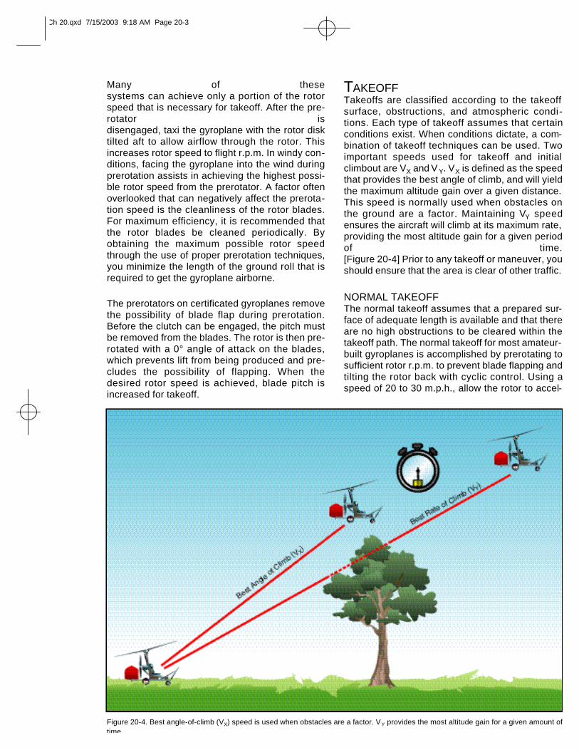
TAKEOFFTakeoffs are classified according to the takeoffsurface, obstructions, and atmospheric condi-tions. Each type of takeoff assumes that certainconditions exist. When conditions dictate, a com-bination of takeoff techniques can be used. Twoimportant speeds used for takeoff and initialclimbout are VX and V Y. VX is defined as the speedthat provides the best angle of climb, and will yieldthe maximum altitude gain over a given distance.This speed is normally used when obstacles onthe ground are a factor. Maintaining VY speedensures the aircraft will climb at its maximum rate,providing the most altitude gain for a given periodof time. [Figure 20-4] Prior to any takeoff or maneuver, youshould ensure that the area is clear of other traffic.
NORMAL TAKEOFFThe normal takeoff assumes that a prepared sur-face of adequate length is available and that thereare no high obstructions to be cleared within thetakeoff path. The normal takeoff for most amateur-built gyroplanes is accomplished by prerotating tosufficient rotor r.p.m. to prevent blade flapping andtilting the rotor back with cyclic control. Using aspeed of 20 to 30 m.p.h., allow the rotor to accel-
Figure 20-4. Best angle-of-climb (VX) speed is used when obstacles are a factor. VY provides the most altitude gain for a given amount oftime.
Ch 20.qxd 7/15/2003 9:18 AM Page 20-3
COMMON ERRORS FOR NORMAL ANDCROSSWIND TAKEOFFS1. Failure to check rotor for proper operation,
track, and r.p.m. prior to takeoff.
2. Improper initial positioning of flight controls.
3. Improper application of power.
4. Poor directional control.
5. Failure to lift off at proper airspeed.
6. Failure to establish and maintain properclimb attitude and airspeed.
7. Drifting from the desired ground track duringthe climb.
SHORT-FIELD TAKEOFFShort-field takeoff and climb procedures may berequired when the usable takeoff surface is short,or when it is restricted by obstructions, such ast r e e s ,powerlines, or buildings, at the departure end. Thetechnique is identical to the normal takeoff, with performance being optimized during each phase.Using the help from wind and propwash, the max-imum rotor r.p.m. should be attained from the pre-rotator and full power applied as soon asappreciable lift is felt. VX climb speed should bemaintained until the obstruction is cleared.Familiarity with the rotor acceleration characteristics and proper technique are essentialfor optimum short-field performance.
If the prerotator is capable of spinning the rotor inexcess of normal flight r.p.m., the stored energymay be used to enhance short-field performance.Once maximum rotor r.p.m. is attained, disengagethe rotor drive, release the brakes, and applypower. As airspeed and rotor r.p.m. increase,apply additional power until full power is achieved.While remaining on the ground, accelerate thegyroplane to a speed just prior to VX. At that point,tilt the disk aft and increase the blade pitch to thenormal in-flight setting. The climb should be at aspeed just under VX until rotor r.p.m. has droppedto normal flight r.p.m. or the obstruction has beencleared. When the obstruction is no longer a fac-tor, increase the airspeed to VY.
COMMON ERRORS
1. Failure to position gyroplane for maximum utilization of available takeoff area.
erate and begin producing lift. As lift increases,move the cyclic forward to decrease the pitchangle on the rotor disc. When appreciable lift isbeing produced, the nose of the aircraft rises, andyou can feel an increase in drag. Using coordi-nated throttle and flight control inputs, balance thegyroplane on the main gear without the nosewheel or tail wheel in contact with the surface. Atthis point, smoothly increase power to full thrustand hold the nose at takeoff attitude with cyclicpressure. The gyroplane will lift off at or near theminimum power required speed for the aircraft. VXshould be used for the initial climb, then VY for theremainder of the climb phase.
A normal takeoff for certificated gyroplanes isaccomplished by prerotating to a rotor r.p.m.slightly above that required for flight and disen-gaging the rotor drive. The brakes are thenreleased and full power is applied. Lift off will notoccur until the blade pitch is increased to the nor-mal in-flight setting and the rotor disk tilted aft.This is normally accomplished at approximately30 to 40 m.p.h. The gyroplane should then beallowed to accelerate to VX for the initial climb, fol-lowed by VY for the remainder of the climb. On anytakeoff in a gyroplane, engine torque causes theaircraft to roll opposite the direction of propellerrotation, and adequate compensation must be made.
CROSSWIND TAKEOFFA crosswind takeoff is much like a normal takeoff,except that you have to use the flight controls to compensate for the crosswind component. Theterm crosswind component refers to that part ofthe wind which acts at right angles to the takeoffpath. Before attempting any crosswind takeoff,refer to the flight manual, if available, or the man-ufacturer’s recommendations for any limitations.
Begin the maneuver by aligning the gyroplane intothe wind as much as possible. At airports with wide runways, you might be able to angle your takeoffroll down the runway to take advantage of as muchheadwind as you can. As airspeed increases,gradually tilt the rotor into the wind and use rudderpressure to maintain runway heading. In most cases, youshould accelerate to a speed slightly faster than nor-mal liftoff speed. As you reach takeoff speed, thedownwind wheel lifts off the ground first, followed bythe upwind wheel. Once airborne, remove thecross-control inputs and establish a crab, if runwayheading is to be maintained. Due to the maneuver-ability of the gyroplane, an immediate turn into thewind after lift off can be safely executed, if this doesnot cause a conflict with existing traffic.
Normally Aspirated—An engine that does not compensate fordecreases in atmospheric pressure through turbocharging or othermeans.
Ch 20.qxd 7/15/2003 9:18 AM Page 20-4
2. Failure to check rotor for proper operation,track, and r.p.m. prior to takeoff.
3. Improper initial positioning of flight controls.
4. Improper application of power.
5. Improper use of brakes.
6. Poor directional control.
7. Failure to lift off at proper airspeed.
8. Failure to establish and maintain properclimb attitude and airspeed.
9. Drifting from the desired ground track duringthe climb.
HIGH-ALTITUDE TAKEOFFA high-altitude takeoff is conducted in a mannervery similar to that of the short-field takeoff, whichachieves maximum performance from the aircraftduring each phase of the maneuver. One impor-tant consideration is that at higher altitudes, rotorr.p.m. is higher for a given blade pitch angle. Thishigher speed is a result of thinner air, and is nec-essary to produce the same amount of lift. Theinertia of the excess rotor speed should not beused in an attempt to enhance climb performance.Another important consideration is the effect ofaltitude on engine performance. As altitudeincreases, the amount of oxygen available forcombustion decreases. In normally aspiratedengines, it may be necessary to adjust the fuel/airmixture to achieve the best possible power output.This process is referred to as “leaning the mix-ture.” If you are considering a high-altitude take-off, and it appears that the climb performance limitof the gyroplane is being approached, do notattempt a takeoff until more favorable conditionsexist.
SOFT-FIELD TAKEOFFA soft field may be defined as any takeoff surfacethat measurably retards acceleration during thetakeoff roll. The objective of the soft-field takeoff isto transfer the weight of the aircraft from the land-ing gear to the rotor as quickly and smoothly aspossible to eliminate the drag caused by surfaces,such as tall grass, soft dirt, or snow. This takeoffrequires liftoff at a speed just above the minimumlevel flight speed for the aircraft. Due to design,many of the smaller gyroplanes have a limitedpitch attitude available, as tail contact with theground prevents high pitch attitudes until in flight.At minimum level flight speed, the pitch attitude isoften such that the tail wheel is lower than themain wheels. When performing a soft-field takeoff,these aircraft require slightly higher liftoff air-speeds to allow for proper tail clearance.
COMMON ERRORS
1. Failure to check rotor for proper operation,track, and r.p.m. prior to takeoff.
2. Improper initial positioning of flight controls.
3. Improper application of power.
4. Allowing gyroplane to lose momentum by slowing or stopping on takeoff surface priorto initiating takeoff.
5. Poor directional control.
6. Improper pitch attitude during lift-off.
7. Settling back to takeoff surface after becom-ing airborne.
8. Failure to establish and maintain properclimb attitude and airspeed.
9. Drifting from the desired ground track duringthe climb.
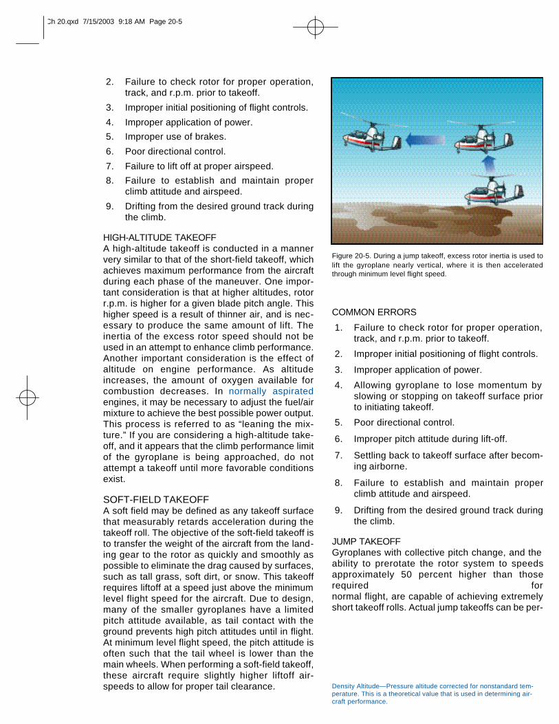
JUMP TAKEOFFGyroplanes with collective pitch change, and the ability to prerotate the rotor system to speedsapproximately 50 percent higher than thoserequired for normal flight, are capable of achieving extremelyshort takeoff rolls. Actual jump takeoffs can be per-
Figure 20-5. During a jump takeoff, excess rotor inertia is used tolift the gyroplane nearly vertical, where it is then acceleratedthrough minimum level flight speed.
Density Altitude—Pressure altitude corrected for nonstandard tem-perature. This is a theoretical value that is used in determining air-craft performance.
Ch 20.qxd 7/15/2003 9:18 AM Page 20-5
formed under the proper conditions. A jump take-off requires no ground roll, making it the mosteffective soft-field and crosswind takeoff proce-dure. [Figure 20-5] A jump takeoff is possiblebecause the energy stored in the blades, as aresult of the higher rotor r.p.m., is used to keep thegyroplane airborne as it accelerates through mini-mum level flight speed. Failure to have sufficientrotor r.p.m. for a jump takeoff results in the gyro-p l a n esettling back to the ground. Before attempting ajump takeoff, it is essential that you first determineif it is possible given the existing conditions byconsulting the relevant performance chart. Shouldconditions of weight, altitude, temperature, orwind leave the successful outcome of the maneu-ver in doubt, it should not be attempted.
The prudent pilot may also use a “rule of thumb”for predicting performance before attempting ajump takeoff. As an example, suppose that a par-ticular gyroplane is known to be able to make ajump takeoff and remain airborne to accelerate toVX at a weight of 1,800 pounds and a density alti-tude of 2,000 feet. Since few takeoffs are madeunder these exact conditions, compensation mustbe made for variations in weight, wind, and den-
sity altitude. The “rule of thumb” being used forthis particular aircraft stipulates that 1,000 feet ofdensity altitude equates with 10 m.p.h. wind or100 pounds of gross weight. To use this equation,
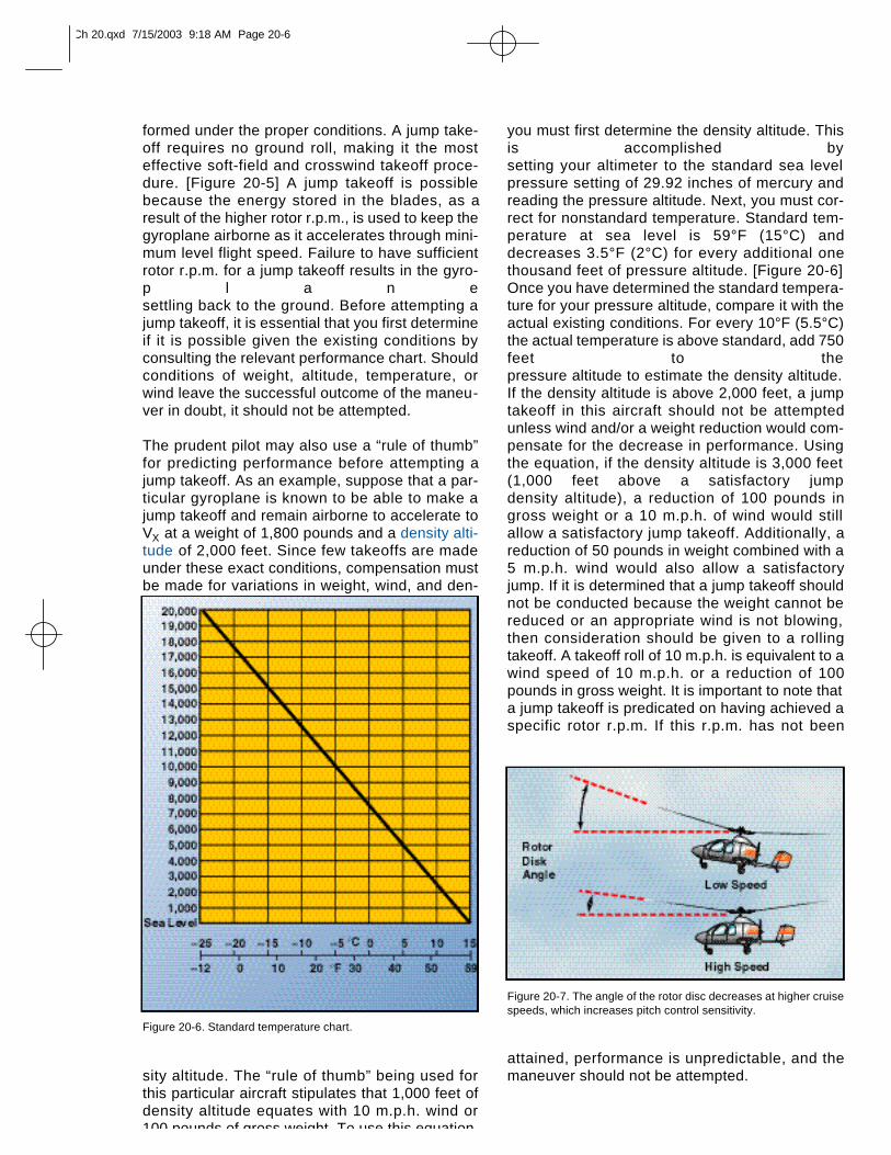
you must first determine the density altitude. Thisis accomplished by setting your altimeter to the standard sea levelpressure setting of 29.92 inches of mercury andreading the pressure altitude. Next, you must cor-rect for nonstandard temperature. Standard tem-perature at sea level is 59°F (15°C) anddecreases 3.5°F (2°C) for every additional onethousand feet of pressure altitude. [Figure 20-6]Once you have determined the standard tempera-ture for your pressure altitude, compare it with theactual existing conditions. For every 10°F (5.5°C)the actual temperature is above standard, add 750feet to the pressure altitude to estimate the density altitude.If the density altitude is above 2,000 feet, a jumptakeoff in this aircraft should not be attemptedunless wind and/or a weight reduction would com-pensate for the decrease in performance. Usingthe equation, if the density altitude is 3,000 feet(1,000 feet above a satisfactory jump density altitude), a reduction of 100 pounds ingross weight or a 10 m.p.h. of wind would stillallow a satisfactory jump takeoff. Additionally, areduction of 50 pounds in weight combined with a5 m.p.h. wind would also allow a satisfactoryjump. If it is determined that a jump takeoff shouldnot be conducted because the weight cannot bereduced or an appropriate wind is not blowing,then consideration should be given to a rollingtakeoff. A takeoff roll of 10 m.p.h. is equivalent to awind speed of 10 m.p.h. or a reduction of 100pounds in gross weight. It is important to note thata jump takeoff is predicated on having achieved aspecific rotor r.p.m. If this r.p.m. has not been
attained, performance is unpredictable, and themaneuver should not be attempted.
Figure 20-7. The angle of the rotor disc decreases at higher cruisespeeds, which increases pitch control sensitivity.
Figure 20-6. Standard temperature chart.
Ch 20.qxd 7/15/2003 9:18 AM Page 20-6
BASIC FLIGHT MANEUVERSConducting flight maneuvers in a gyroplane is dif-ferent than in most other aircraft. Because of thewide variety in designs, many gyroplanes haveonly basic instruments available, and the pilot isoften exposed to the airflow. In addition, the visualclues found on other aircraft, such as cowlings,wings, and windshields might not be part of yourgyroplane’s design. Therefore, much morereliance is placed on pilot interpretation of flight attitude and the “feel” of thegyroplane than in other types of aircraft. Acquiringthe skills to precisely control a gyroplane can be a challenging and rewarding experience, butrequires dedication and the direction of a compe-tent instructor.
STRAIGHT-AND-LEVEL FLIGHTStraight-and-level flight is conducted by maintain-ing a constant altitude and a constant heading. Inflight, a gyroplane essentially acts as a plumb sus-pended from the rotor. As such, torque forces fromthe engine cause the airframe to be deflected afew degrees out of the vertical plane. This veryslight “out of vertical” condition should be ignored and the aircraft flownto maintain a constant heading.
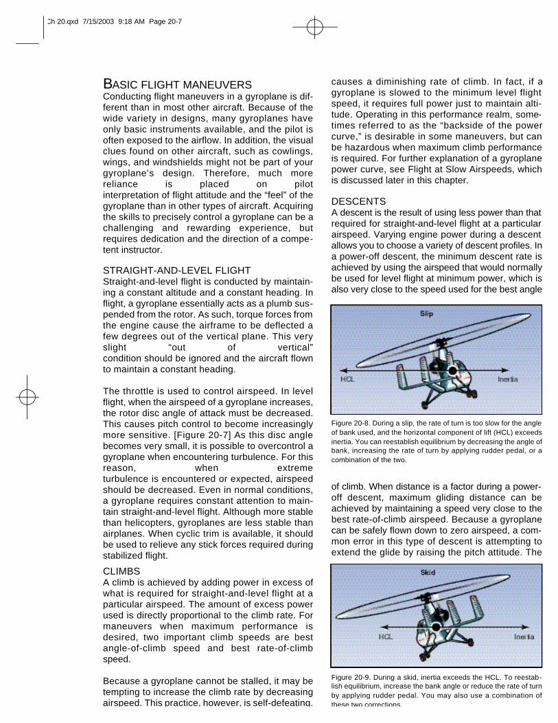
The throttle is used to control airspeed. In levelflight, when the airspeed of a gyroplane increases,the rotor disc angle of attack must be decreased.This causes pitch control to become increasinglymore sensitive. [Figure 20-7] As this disc anglebecomes very small, it is possible to overcontrol agyroplane when encountering turbulence. For thisreason, when extreme turbulence is encountered or expected, airspeedshould be decreased. Even in normal conditions,a gyroplane requires constant attention to main-tain straight-and-level flight. Although more stablethan helicopters, gyroplanes are less stable thanairplanes. When cyclic trim is available, it shouldbe used to relieve any stick forces required duringstabilized flight.
CLIMBS A climb is achieved by adding power in excess ofwhat is required for straight-and-level flight at aparticular airspeed. The amount of excess powerused is directly proportional to the climb rate. Formaneuvers when maximum performance isdesired, two important climb speeds are bestangle-of-climb speed and best rate-of-climbspeed.
Because a gyroplane cannot be stalled, it may betempting to increase the climb rate by decreasingairspeed. This practice, however, is self-defeating.
causes a diminishing rate of climb. In fact, if agyroplane is slowed to the minimum level flightspeed, it requires full power just to maintain alti-tude. Operating in this performance realm, some-times referred to as the “backside of the powercurve,” is desirable in some maneuvers, but canbe hazardous when maximum climb performanceis required. For further explanation of a gyroplanepower curve, see Flight at Slow Airspeeds, whichis discussed later in this chapter.
DESCENTS A descent is the result of using less power than thatrequired for straight-and-level flight at a particular airspeed. Varying engine power during a descentallows you to choose a variety of descent profiles. Ina power-off descent, the minimum descent rate isachieved by using the airspeed that would normallybe used for level flight at minimum power, which isalso very close to the speed used for the best angle
of climb. When distance is a factor during a power-off descent, maximum gliding distance can beachieved by maintaining a speed very close to thebest rate-of-climb airspeed. Because a gyroplanecan be safely flown down to zero airspeed, a com-mon error in this type of descent is attempting toextend the glide by raising the pitch attitude. The
Figure 20-8. During a slip, the rate of turn is too slow for the angleof bank used, and the horizontal component of lift (HCL) exceedsinertia. You can reestablish equilibrium by decreasing the angle ofbank, increasing the rate of turn by applying rudder pedal, or acombination of the two.
Figure 20-9. During a skid, inertia exceeds the HCL. To reestab-lish equilibrium, increase the bank angle or reduce the rate of turnby applying rudder pedal. You may also use a combination ofthese two corrections.
Ch 20.qxd 7/15/2003 9:18 AM Page 20-7
result is a higher rate of descent and less distancebeing covered. For this reason, proper glide speedshould be adhered to closely. Should a strong head-wind exist, while attempting to achieve the maxi-mum distance during a glide, a rule of thumb toachieve the greatest distance is to increase the glidespeed by approximately 25 percent of the head-wind. The attitude of the gyroplane for best glideperformance is learned with experience, and slightpitch adjustments are made for the proper airspeed.If a descent is needed to lose excess altitude, slow-ing the gyroplane to below the best glide speedincreases the rate of descent. Typically, slowing tozero airspeed results in a descent rate twice that ofmaintaining the best glide speed.
TURNSTurns are made in a gyroplane by banking the rotordisc with cyclic control. Once the area, in the direc-tion of the turn, has been cleared for traffic, applysideward pressure on the cyclic until the desiredbank angle is achieved. The speed at which thegyroplane enters the bank is dependent on how farthe cyclic is displaced. When the desired bankangle is reached, return the cyclic to the neutralposition. The rudder pedals are used to keep thegyroplane in longitudinal trim throughout the turn,but not to assist in establishing the turn.
The bank angle used for a turn directly affects therate of turn. As the bank is steepened, the turnrate increases, but more power is required tomaintain altitude. A bank angle can be reachedwhere all available power is required, with any fur-ther increase in bank resulting in a loss of airspeedor altitude. Turns during a climb should be made atthe minimum angle of bank necessary, as higherbank angles would require more power that wouldotherwise be available for the climb. Turns whilegliding increase the rate of descent and may beused as an effective way of losing excess altitude.
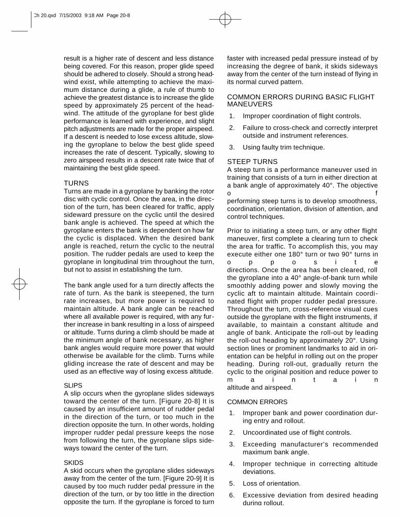
SLIPSA slip occurs when the gyroplane slides sidewaystoward the center of the turn. [Figure 20-8] It iscaused by an insufficient amount of rudder pedalin the direction of the turn, or too much in thedirection opposite the turn. In other words, holdingimproper rudder pedal pressure keeps the nosefrom following the turn, the gyroplane slips side-ways toward the center of the turn.
SKIDSA skid occurs when the gyroplane slides sidewaysaway from the center of the turn. [Figure 20-9] It iscaused by too much rudder pedal pressure in thedirection of the turn, or by too little in the directionopposite the turn. If the gyroplane is forced to turn
faster with increased pedal pressure instead of byincreasing the degree of bank, it skids sidewaysaway from the center of the turn instead of flying inits normal curved pattern.
COMMON ERRORS DURING BASIC FLIGHTMANEUVERS
1. Improper coordination of flight controls.
2. Failure to cross-check and correctly interpret outside and instrument references.
3. Using faulty trim technique.
STEEP TURNSA steep turn is a performance maneuver used in training that consists of a turn in either direction ata bank angle of approximately 40°. The objectiveo fperforming steep turns is to develop smoothness,coordination, orientation, division of attention, andcontrol techniques.
Prior to initiating a steep turn, or any other flightmaneuver, first complete a clearing turn to checkthe area for traffic. To accomplish this, you mayexecute either one 180° turn or two 90° turns ino p p o s i t edirections. Once the area has been cleared, rollthe gyroplane into a 40° angle-of-bank turn whilesmoothly adding power and slowly moving thecyclic aft to maintain altitude. Maintain coordi-nated flight with proper rudder pedal pressure.Throughout the turn, cross-reference visual cuesoutside the gyroplane with the flight instruments, ifavailable, to maintain a constant altitude andangle of bank. Anticipate the roll-out by leadingthe roll-out heading by approximately 20°. Usingsection lines or prominent landmarks to aid in ori-entation can be helpful in rolling out on the properheading. During roll-out, gradually return thecyclic to the original position and reduce power tom a i n t a i naltitude and airspeed.
COMMON ERRORS
1. Improper bank and power coordination dur-ing entry and rollout.
2. Uncoordinated use of flight controls.
3. Exceeding manufacturer’s recommendedmaximum bank angle.
4. Improper technique in correcting altitude deviations.
5. Loss of orientation.
6. Excessive deviation from desired headingduring rollout.
Ch 20.qxd 7/15/2003 9:18 AM Page 20-8
GROUND REFERENCE MANEUVERSGround reference maneuvers are training exer-cises flown to help you develop a division of atten-tion between the flight path and groundreferences, while controlling the gyroplane andwatching for other aircraft in the vicinity. Prior to each maneuver, aclearing turn should be accomplished to ensurethe practice area is free of conflicting traffic.
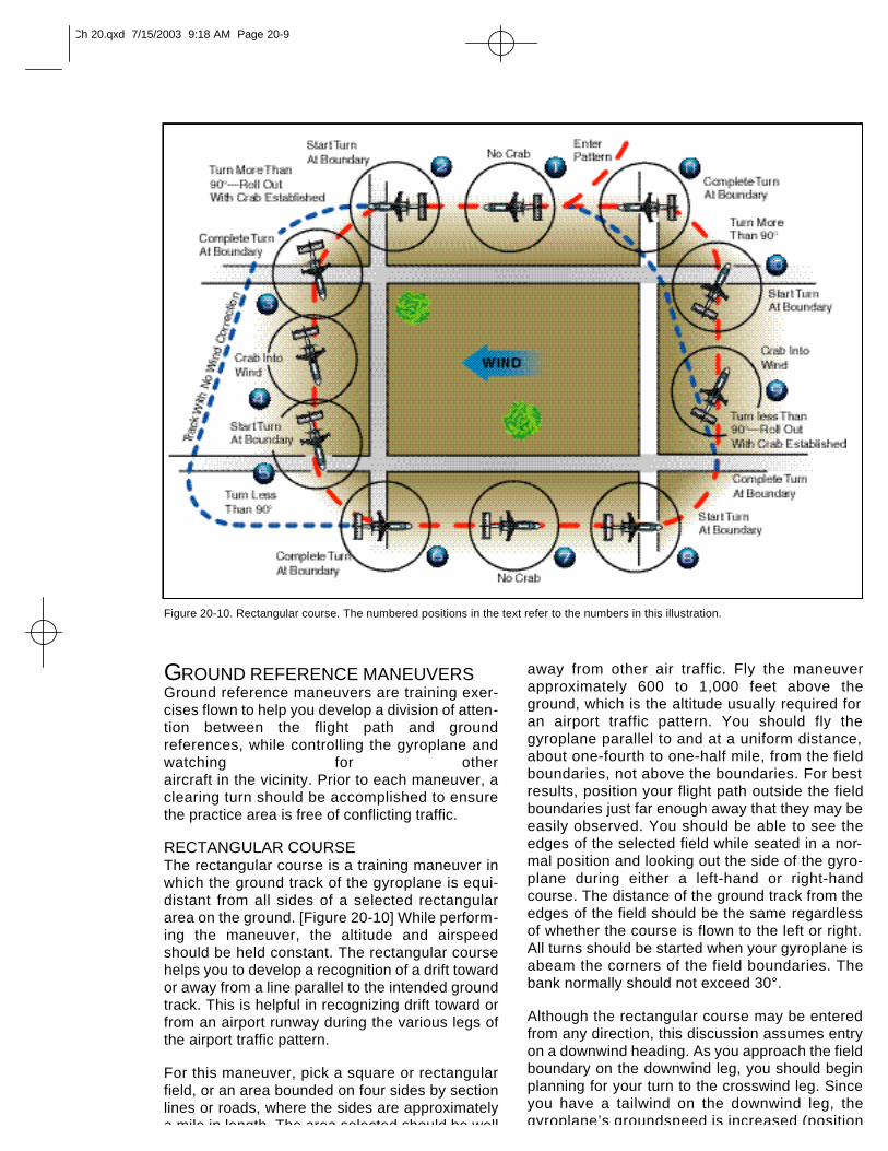
RECTANGULAR COURSEThe rectangular course is a training maneuver inwhich the ground track of the gyroplane is equi-distant from all sides of a selected rectangulararea on the ground. [Figure 20-10] While perform-ing the maneuver, the altitude and airspeedshould be held constant. The rectangular coursehelps you to develop a recognition of a drift towardor away from a line parallel to the intended groundtrack. This is helpful in recognizing drift toward orfrom an airport runway during the various legs ofthe airport traffic pattern.
For this maneuver, pick a square or rectangularfield, or an area bounded on four sides by sectionlines or roads, where the sides are approximatelya mile in length. The area selected should be well
away from other air traffic. Fly the maneuverapproximately 600 to 1,000 feet above theground, which is the altitude usually required foran airport traffic pattern. You should fly the gyroplane parallel to and at a uniform distance,about one-fourth to one-half mile, from the fieldboundaries, not above the boundaries. For bestresults, position your flight path outside the fieldboundaries just far enough away that they may beeasily observed. You should be able to see theedges of the selected field while seated in a nor-mal position and looking out the side of the gyro-plane during either a left-hand or right-handcourse. The distance of the ground track from theedges of the field should be the same regardlessof whether the course is flown to the left or right.All turns should be started when your gyroplane isabeam the corners of the field boundaries. Thebank normally should not exceed 30°.
Although the rectangular course may be enteredfrom any direction, this discussion assumes entryon a downwind heading. As you approach the fieldboundary on the downwind leg, you should beginplanning for your turn to the crosswind leg. Sinceyou have a tailwind on the downwind leg, thegyroplane’s groundspeed is increased (position
Figure 20-10. Rectangular course. The numbered positions in the text refer to the numbers in this illustration.
Ch 20.qxd 7/15/2003 9:18 AM Page 20-9
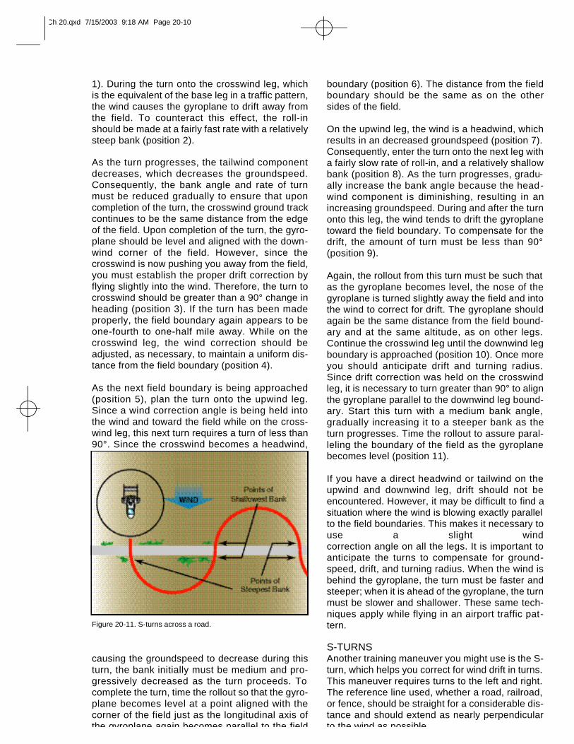
1). During the turn onto the crosswind leg, whichis the equivalent of the base leg in a traffic pattern,the wind causes the gyroplane to drift away fromthe field. To counteract this effect, the roll-inshould be made at a fairly fast rate with a relativelysteep bank (position 2).
As the turn progresses, the tailwind componentdecreases, which decreases the groundspeed.Consequently, the bank angle and rate of turnmust be reduced gradually to ensure that uponcompletion of the turn, the crosswind ground trackcontinues to be the same distance from the edgeof the field. Upon completion of the turn, the gyro-plane should be level and aligned with the down-wind corner of the field. However, since thecrosswind is now pushing you away from the field,you must establish the proper drift correction byflying slightly into the wind. Therefore, the turn tocrosswind should be greater than a 90° change inheading (position 3). If the turn has been madeproperly, the field boundary again appears to beone-fourth to one-half mile away. While on thecrosswind leg, the wind correction should beadjusted, as necessary, to maintain a uniform dis-tance from the field boundary (position 4).
As the next field boundary is being approached(position 5), plan the turn onto the upwind leg.Since a wind correction angle is being held intothe wind and toward the field while on the cross-wind leg, this next turn requires a turn of less than90°. Since the crosswind becomes a headwind,
causing the groundspeed to decrease during thisturn, the bank initially must be medium and pro-gressively decreased as the turn proceeds. Tocomplete the turn, time the rollout so that the gyro-plane becomes level at a point aligned with thecorner of the field just as the longitudinal axis ofthe gyroplane again becomes parallel to the field
boundary (position 6). The distance from the fieldboundary should be the same as on the othersides of the field.
On the upwind leg, the wind is a headwind, whichresults in an decreased groundspeed (position 7).Consequently, enter the turn onto the next leg witha fairly slow rate of roll-in, and a relatively shallowbank (position 8). As the turn progresses, gradu-ally increase the bank angle because the head-wind component is diminishing, resulting in anincreasing groundspeed. During and after the turnonto this leg, the wind tends to drift the gyroplanetoward the field boundary. To compensate for thedrift, the amount of turn must be less than 90°(position 9).
Again, the rollout from this turn must be such thatas the gyroplane becomes level, the nose of thegyroplane is turned slightly away the field and intothe wind to correct for drift. The gyroplane shouldagain be the same distance from the field bound-ary and at the same altitude, as on other legs.Continue the crosswind leg until the downwind legboundary is approached (position 10). Once moreyou should anticipate drift and turning radius.Since drift correction was held on the crosswindleg, it is necessary to turn greater than 90° to alignthe gyroplane parallel to the downwind leg bound-ary. Start this turn with a medium bank angle,gradually increasing it to a steeper bank as theturn progresses. Time the rollout to assure paral-leling the boundary of the field as the gyroplanebecomes level (position 11).
If you have a direct headwind or tailwind on theupwind and downwind leg, drift should not beencountered. However, it may be difficult to find asituation where the wind is blowing exactly parallelto the field boundaries. This makes it necessary touse a slight wind correction angle on all the legs. It is important toanticipate the turns to compensate for ground-speed, drift, and turning radius. When the wind isbehind the gyroplane, the turn must be faster andsteeper; when it is ahead of the gyroplane, the turnmust be slower and shallower. These same tech-niques apply while flying in an airport traffic pat-tern.
S-TURNSAnother training maneuver you might use is the S-turn, which helps you correct for wind drift in turns.This maneuver requires turns to the left and right.The reference line used, whether a road, railroad,or fence, should be straight for a considerable dis-tance and should extend as nearly perpendicularto the wind as possible.
Figure 20-11. S-turns across a road.
Ch 20.qxd 7/15/2003 9:18 AM Page 20-10
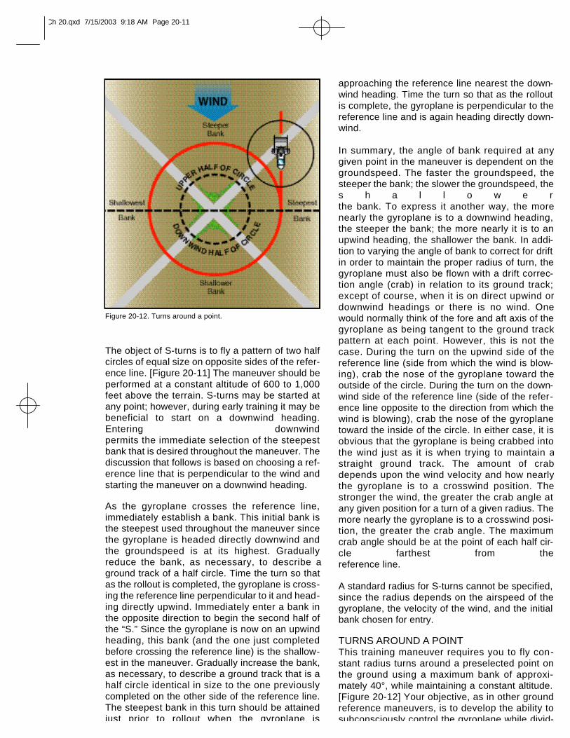
The object of S-turns is to fly a pattern of two half circles of equal size on opposite sides of the refer-ence line. [Figure 20-11] The maneuver should be performed at a constant altitude of 600 to 1,000feet above the terrain. S-turns may be started atany point; however, during early training it may bebeneficial to start on a downwind heading.Entering downwind permits the immediate selection of the steepestbank that is desired throughout the maneuver. Thediscussion that follows is based on choosing a ref-erence line that is perpendicular to the wind andstarting the maneuver on a downwind heading.
As the gyroplane crosses the reference line,immediately establish a bank. This initial bank isthe steepest used throughout the maneuver sincethe gyroplane is headed directly downwind andthe groundspeed is at its highest. Graduallyreduce the bank, as necessary, to describe aground track of a half circle. Time the turn so thatas the rollout is completed, the gyroplane is cross-ing the reference line perpendicular to it and head-ing directly upwind. Immediately enter a bank inthe opposite direction to begin the second half ofthe “S.” Since the gyroplane is now on an upwindheading, this bank (and the one just completedbefore crossing the reference line) is the shallow-est in the maneuver. Gradually increase the bank,as necessary, to describe a ground track that is ahalf circle identical in size to the one previouslycompleted on the other side of the reference line.The steepest bank in this turn should be attainedjust prior to rollout when the gyroplane is
approaching the reference line nearest the down-wind heading. Time the turn so that as the rolloutis complete, the gyroplane is perpendicular to thereference line and is again heading directly down-wind.
In summary, the angle of bank required at anygiven point in the maneuver is dependent on thegroundspeed. The faster the groundspeed, thesteeper the bank; the slower the groundspeed, thes h a l l o w e rthe bank. To express it another way, the morenearly the gyroplane is to a downwind heading,the steeper the bank; the more nearly it is to anupwind heading, the shallower the bank. In addi-tion to varying the angle of bank to correct for driftin order to maintain the proper radius of turn, thegyroplane must also be flown with a drift correc-tion angle (crab) in relation to its ground track;except of course, when it is on direct upwind ordownwind headings or there is no wind. Onewould normally think of the fore and aft axis of thegyroplane as being tangent to the ground trackpattern at each point. However, this is not thecase. During the turn on the upwind side of thereference line (side from which the wind is blow-ing), crab the nose of the gyroplane toward theoutside of the circle. During the turn on the down-wind side of the reference line (side of the refer-ence line opposite to the direction from which thewind is blowing), crab the nose of the gyroplanetoward the inside of the circle. In either case, it isobvious that the gyroplane is being crabbed intothe wind just as it is when trying to maintain astraight ground track. The amount of crabdepends upon the wind velocity and how nearlythe gyroplane is to a crosswind position. Thestronger the wind, the greater the crab angle atany given position for a turn of a given radius. Themore nearly the gyroplane is to a crosswind posi-tion, the greater the crab angle. The maximumcrab angle should be at the point of each half cir-cle farthest from the reference line.
A standard radius for S-turns cannot be specified,since the radius depends on the airspeed of thegyroplane, the velocity of the wind, and the initialbank chosen for entry.
TURNS AROUND A POINTThis training maneuver requires you to fly con-stant radius turns around a preselected point onthe ground using a maximum bank of approxi-mately 40°, while maintaining a constant altitude.[Figure 20-12] Your objective, as in other groundreference maneuvers, is to develop the ability tosubconsciously control the gyroplane while divid-
Figure 20-12. Turns around a point.
Ch 20.qxd 7/15/2003 9:18 AM Page 20-11
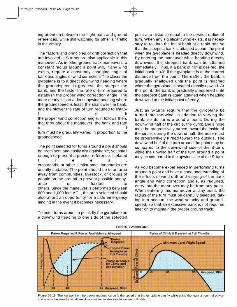
ing attention between the flight path and groundreferences, while still watching for other air trafficin the vicinity.
The factors and principles of drift correction thatare involved in S-turns are also applicable in thismaneuver. As in other ground track maneuvers, aconstant radius around a point will, if any windexists, require a constantly changing angle ofbank and angles of wind correction. The closer thegyroplane is to a direct downwind heading wherethe groundspeed is greatest, the steeper thebank, and the faster the rate of turn required toestablish the proper wind correction angle. Themore nearly it is to a direct upwind heading wherethe groundspeed is least, the shallower the bank,and the slower the rate of turn required to estab-l i s hthe proper wind correction angle. It follows then, that throughout the maneuver, the bank and rateo fturn must be gradually varied in proportion to the groundspeed.
The point selected for turns around a point shouldbe prominent and easily distinguishable, yet smallenough to present a precise reference. Isolatedt r e e s ,crossroads, or other similar small landmarks areusually suitable. The point should be in an areaaway from communities, livestock, or groups ofpeople on the ground to prevent possible annoy-ance or hazard to others. Since the maneuver is performed between600 and 1,000 feet AGL, the area selected shouldalso afford an opportunity for a safe emergencylanding in the event it becomes necessary.
To enter turns around a point, fly the gyroplane ona downwind heading to one side of the selected
point at a distance equal to the desired radius ofturn. When any significant wind exists, it is neces-sary to roll into the initial bank at a rapid rate sothat the steepest bank is attained abeam the pointwhen the gyroplane is headed directly downwind.By entering the maneuver while heading directlydownwind, the steepest bank can be attainedimmediately. Thus, if a bank of 40° is desired, theinitial bank is 40° if the gyroplane is at the correctdistance from the point. Thereafter, the bank isgradually shallowed until the point is reachedwhere the gyroplane is headed directly upwind. Atthis point, the bank is gradually steepened untilthe steepest bank is again attained when headingdownwind at the initial point of entry.
Just as S-turns require that the gyroplane beturned into the wind, in addition to varying thebank, so do turns around a point. During thedownwind half of the circle, the gyroplane’s nosemust be progressively turned toward the inside ofthe circle; during the upwind half, the nose mustbe progressively turned toward the outside. Thedownwind half of the turn around the point may becompared to the downwind side of the S-turn,while the upwind half of the turn around a pointmay be compared to the upwind side of the S-turn.
As you become experienced in performing turnsaround a point and have a good understanding ofthe effects of wind drift and varying of the bankangle and wind correction angle, as required,entry into the maneuver may be from any point.When entering this maneuver at any point, theradius of the turn must be carefully selected, tak-ing into account the wind velocity and ground-speed, so that an excessive bank is not requiredlater on to maintain the proper ground track.
Figure 20-13. The low point on the power required curve is the speed that the gyroplane can fly while using the least amount of power,and is also the speed that will result in a minimum sink rate in a power-off glide.
Ch 20.qxd 7/15/2003 9:18 AM Page 20-12
COMMON ERRORS DURING GROUNDREFERENCE MANEUVERS
1. Faulty entry technique.
2. Poor planning, orientation, or division of attention.
3. Uncoordinated flight control application.
4. Improper correction for wind drift.
5. An unsymmetrical ground track during S-turns across a road.
6. Failure to maintain selected altitude or air-speed.
7. Selection of a ground reference where thereis no suitable emergency landing site.
FLIGHT AT SLOW AIRSPEEDSThe purpose of maneuvering during slow flight isto help you develop a feel for controlling the gyro-plane at slow airspeeds, as well as gain an under-standing of how load factor, pitch attitude,airspeed, and altitude control relate to each other.
Like airplanes, gyroplanes have a specific amountof power that is required for flight at various air-speeds, and a fixed amount of power available fromthe engine. This data can be charted in a graph for-mat. [Figure 20-13] The lowest point of the powerrequired curve represents the speed at which thegyroplane will fly in level flight while using the leastamount of power. To fly faster than this speed, orslower, requires more power. While practicing slow flight in a gyroplane, you will likelybe operating in the performance realm on the chartthat is left of the minimum power required speed.This is often referred to as the “backside of thepower curve,” or flying “behind the power curve.” At these speeds,as pitch is increased to slow the gyroplane, moreand more power is required to maintain level flight.At the point where maximum power available isbeing used, no further reduction in airspeed is possible without ini-tiating a descent. This speed is referred to as theminimum level flight speed. Because there is noexcess power available for acceleration, recoveryfrom minimum level flight speed requires loweringthe nose of the gyroplane and using altitude toregain airspeed. For this reason, it is essential topractice slow flight at altitudes that allow sufficientheight for a safe recovery. Unintentionally flying a gyroplane on the backside of the powercurve during approach and landing can bee x t r e m e l yhazardous. Should a go-around become neces-s a r y ,
sufficient altitude to regain airspeed and initiate aclimb may not be available, and ground contactmay be unavoidable.
Flight at slow airspeeds is usually conducted atairspeeds 5 to 10 m.p.h. above the minimum levelflight airspeed. When flying at slow airspeeds, it isimportant that your control inputs be smooth andslow to prevent a rapid loss of airspeed due to thehigh drag increases with small changes in pitchattitude. In addition, turns should be limited toshallow bank angles. In order to prevent losingaltitude during turns, power must be added.Directional control remains very good while flyingat slow airspeeds, because of the high velocityslipstream produced by the increased enginepower.
Recovery to cruise flight speed is made by lower-ing the nose and increasing power. When thedesired speed is reached, reduce power to thenormal cruise power setting.
COMMON ERRORS
1. Improper entry technique.
2. Failure to establish and maintain an appro-priate airspeed.
3. Excessive variations of altitude and headingwhen a constant altitude and heading are specified.
4. Use of too steep a bank angle.
5. Rough or uncoordinated control technique.
HIGH RATE OF DESCENTA gyroplane will descend at a high rate when flownat very low forward airspeeds. This maneuver maybe entered intentionally when a steep descent isdesired, and can be performed with or withoutpower. An unintentional high rate of descent canalso occur as a result of failing to monitor andmaintain proper airspeed. In powered flight, if thegyroplane is flown below minimum level flightspeed, a descent results even though full enginepower is applied. Further reducing the airspeedwith aft cyclic increases the rate of descent. Forgyroplanes with a high thrust-to-weight ratio, thismaneuver creates a very high pitch attitude. Torecover, the nose of the gyroplane must loweredslightly to exchange altitude for an increase in air-speed.
When operating a gyroplane in an unpoweredglide, slowing to below the best glide speed canalso result in a high rate of descent. As airspeeddecreases, the rate of descent increases, reach-
Ch 20.qxd 7/15/2003 9:18 AM Page 20-13
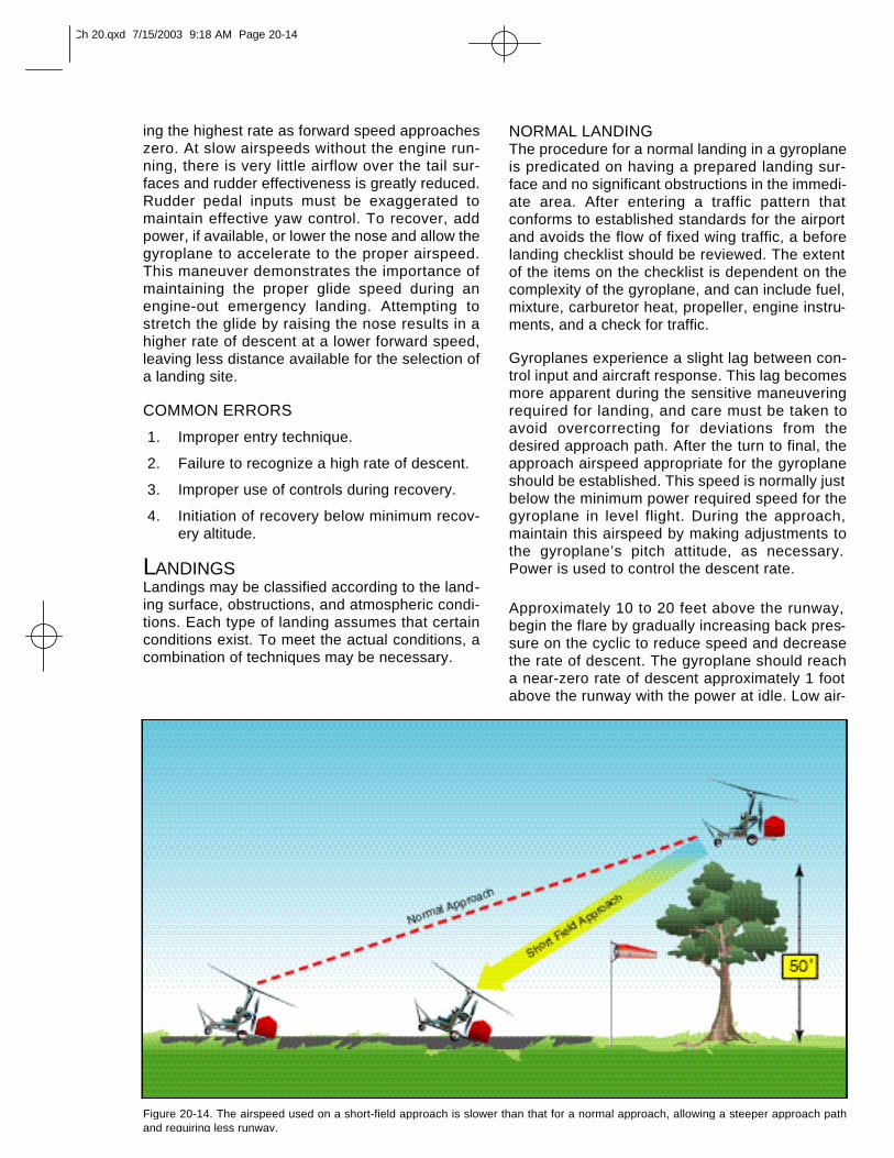
ing the highest rate as forward speed approacheszero. At slow airspeeds without the engine run-ning, there is very little airflow over the tail sur-faces and rudder effectiveness is greatly reduced.Rudder pedal inputs must be exaggerated tomaintain effective yaw control. To recover, addpower, if available, or lower the nose and allow thegyroplane to accelerate to the proper airspeed.This maneuver demonstrates the importance ofmaintaining the proper glide speed during anengine-out emergency landing. Attempting tostretch the glide by raising the nose results in ahigher rate of descent at a lower forward speed,leaving less distance available for the selection ofa landing site.
COMMON ERRORS
1. Improper entry technique.
2. Failure to recognize a high rate of descent.
3. Improper use of controls during recovery.
4. Initiation of recovery below minimum recov-ery altitude.
LANDINGSLandings may be classified according to the land-ing surface, obstructions, and atmospheric condi-tions. Each type of landing assumes that certainconditions exist. To meet the actual conditions, acombination of techniques may be necessary.
NORMAL LANDINGThe procedure for a normal landing in a gyroplaneis predicated on having a prepared landing sur-face and no significant obstructions in the immedi-ate area. After entering a traffic pattern thatconforms to established standards for the airportand avoids the flow of fixed wing traffic, a beforelanding checklist should be reviewed. The extentof the items on the checklist is dependent on thecomplexity of the gyroplane, and can include fuel,mixture, carburetor heat, propeller, engine instru-ments, and a check for traffic.
Gyroplanes experience a slight lag between con-trol input and aircraft response. This lag becomesmore apparent during the sensitive maneuveringrequired for landing, and care must be taken toavoid overcorrecting for deviations from thedesired approach path. After the turn to final, theapproach airspeed appropriate for the gyroplaneshould be established. This speed is normally justbelow the minimum power required speed for thegyroplane in level flight. During the approach,maintain this airspeed by making adjustments tothe gyroplane’s pitch attitude, as necessary.Power is used to control the descent rate.
Approximately 10 to 20 feet above the runway,begin the flare by gradually increasing back pres-sure on the cyclic to reduce speed and decreasethe rate of descent. The gyroplane should reacha near-zero rate of descent approximately 1 footabove the runway with the power at idle. Low air-
Figure 20-14. The airspeed used on a short-field approach is slower than that for a normal approach, allowing a steeper approach pathand requiring less runway.
Ch 20.qxd 7/15/2003 9:18 AM Page 20-14
speed combined with a minimum of propwashover the tail surfaces reduces rudder effectiveness during the flare. If a yaw moment isencountered, use whatever rudder control isrequired to maintain the desired heading. Thegyroplane should be kept laterally level and withthe longitudinal axis in the direction of groundtrack. Landing with sideward motion can damagethe landing gear and must be avoided. In a full-flare landing, attempt to hold the gyroplane justoff the runway by steadily increasing back pres-sure on the cyclic. This causes the gyroplane tosettle slowly to the runway in a slightly nose-highattitude as forward momentum dissipates.
Ground roll for a full-flare landing is typicallyunder 50 feet, and touchdown speed under 20m.p.h. If a 20 m.p.h. or greater headwind exists, itmay be necessary to decrease the length of theflare and allow the gyroplane to touch down at aslightly higher airspeed to prevent it from rollingbackward on landing. After touchdown, rotorr.p.m. decays rather rapidly. On landings wherebrakes are required immediately after touchdown,apply them lightly, as the rotor is still carryingmuch of the weight of the aircraft and too muchbraking causes the tires to skid.
SHORT-FIELD LANDING A short-field landing is necessary when you havea relatively short landing area or when anapproach must be made over obstacles that limitthe available landing area. When practicing short-field landings, assume you are making theapproach and landing over a 50-foot obstructionin the approach area.
To conduct a short-field approach and landing,follow normal procedures until you are estab-lished on the final approach segment. At thispoint, use aft cyclic to reduce airspeed below thespeed for minimum sink. By decreasing speed,sink rate increases and a steeper approach pathis achieved, minimizing the distance betweenclearing the obstacle and making contact with the surface. [Figure 20-14]The approach speed must remain fast enough,however, to allow the flare to arrest the forwardand vertical speed of the gyroplane. If theapproach speed is too low, the remaining verti-cal momentum will result in a hard landing. On ashort-field landing with a slight headwind, atouchdown with no ground roll is possible.Without wind, the ground roll is normally lessthan 50 feet.
SOFT-FIELD LANDINGUse the soft-field landing technique when thelanding surface presents high wheel drag, such asmud, snow, sand, tall grass or standing water. Theobjective is to transfer the weight of the gyroplanefrom the rotor to the landing gear as gently andslowly as possible. With a headwind close to thetouchdown speed of the gyroplane, a power approach can be made closeto the minimum level flight speed. As you increasethe nose pitch attitude just prior to touchdown, addadditional power to cushion the landing. However,power should be removed, just as the wheels areready to touch. This results is a very slow, gentletouchdown. In a strong headwind, avoid allowingthe gyroplane to roll rearward at touchdown. Aftertouchdown, smoothly and gently lower the nose-wheel to the ground. Minimize the use of brakes,and remain aware that the nosewheel could dig inthe soft surface.
When no wind exists, use a steep approach simi-lar to a short-field landing so that the forwardspeed can be dissipated during the flare. Use thethrottle to cushion the touchdown.
CROSSWIND LANDING Crosswind landing technique is normally used ingyroplanes when a crosswind of approximately 15m.p.h. or less exists. In conditions with highercrosswinds, it becomes very difficult, if not impos-sible, to maintain adequate compensation for thecrosswind. In these conditions, the slow touch-down speed of a gyroplane allows a much saferoption of turning directly into the wind and landingwith little or no ground roll. Deciding when to usethis technique, however, may be complicated by gusting winds or the characteris-tics of the particular landing area.
Ch 20.qxd 7/15/2003 9:18 AM Page 20-15
On final approach, establish a crab angle into thewind to maintain a ground track that is aligned withthe extended centerline of the runway. Just before touchdown, remove the crab angle and bank the gyroplane slightly into the wind to prevent drift.Maintain longitudinal alignment with the runwayusing the rudder. In higher crosswinds, if full rud-der deflection is not sufficient to maintain align-ment with the runway, applying a slight amount ofpower can increase rudder effectiveness. Thelength of the flare should be reduced to allow aslightly higher touchdown speed than that used ina no-wind landing. Touchdown is made on theupwind main wheel first, with the other main wheelsettling to the runway as forward momentum islost. After landing, continue to keep the rotor tiltedinto the wind to maintain positive control during therollout.
HIGH-ALTITUDE LANDING A high-altitude landing assumes a density altitudenear the limit of what is considered good climbperformance for the gyroplane. When using thesame indicated airspeed as that used for a normal approach atlower altitude, a high density altitude results inhigher rotor r.p.m. and a slightly higher rate ofdescent. The greater vertical velocity is a result ofhigher true airspeed as compared with that at lowaltitudes. When practicing high-altitude landings,it is prudent to first learn normal landings with aflare and roll out. Full flare, no roll landings shouldnot be attempted until a good feel for aircraftresponse at higher altitudes has been acquired.As with high-altitude takeoffs, it is also importantto consider the effects of higher altitude on engine performance.
COMMON ERRORS DURING LANDING
1. Failure to establish and maintain a stabilizedapproach.
2. Improper technique in the use of power.
3. Improper technique during flare or touch-down.
4. Touchdown at too low an airspeed withstrong headwinds, causing a rearward roll.
5. Poor directional control after touchdown.
6. Improper use of brakes.
GO-AROUNDThe go-around is used to abort a landingapproach when unsafe factors for landing are rec-ognized. If the decision is made early in theapproach to go around, normal climb proceduresutilizing VX and VY should be used. A late decision
to go around, such as after the full flare has beeninitiated, may result in an airspeed where powerrequired is greater than power available. Whenthis occurs, a touchdown becomes unavoidableand it may be safer to proceed with the landingthan to sustain an extended ground roll that wouldbe required to go around. Also, the pitch attitudeof the gyroplane in the flare is high enough thatthe tail would be considerably lower than the maingear, and a touch down with power on wouldresult in a sudden pitch down and acceleration ofthe aircraft. Control of the gyroplane under thesecircumstances may be difficult. Consequently, thedecision to go around should be made as early aspossible, before the speed is reduced below thepoint that power required exceeds power avail -able.
COMMON ERRORS
1. Failure to recognize a situation where a go-around is necessary.
2. Improper application of power.
3. Failure to control pitch attitude.
4. Failure to maintain recommended airspeeds.
5. Failure to maintain proper track during climbout.
AFTER LANDING AND SECURING The after-landing checklist should include suchitems as the transponder, cowl flaps, fuel pumps,lights, and magneto checks, when so equipped.The rotor blades demand special considerationafter landing, as turning rotor blades can be haz-ardous to others. Never enter an area where peo-ple or obstructions are present with the rotorturning. To assist the rotor in slowing, tilt the cycliccontrol into the prevailing wind or face the gyro-plane downwind. When slowed to under approxi-mately 75 r.p.m., the rotor brake may be applied, ifavailable. Use caution as the rotor slows, asexcess taxi speed or high winds could causeblade flap to occur. The blades should bedepitched when taxiing if a collective control isavailable. When leaving the gyroplane, alwayssecure the blades with a tiedown or rotor brake.
Ch 20.qxd 7/15/2003 9:18 AM Page 20-16
Gyroplanes are quite reliable, however emergen-cies do occur, whether a result of mechanical fail-ure or pilot error. By having a thorough knowledgeof the gyroplane and its systems, you will be able tomore readily handle the situation. In addition, byknowing the conditions which can lead to anemergency, many potential accidents can beavoided.
ABORTED TAKEOFFPrior to every takeoff, consideration must be givento a course of action should the takeoff becomeundesirable or unsafe. Mechanical failures,obstructions on the takeoff surface, and changingweather conditions are all factors that could com-promise the safety of a takeoff and constitute areason to abort. The decision to abort a takeoffshould be definitive and made as soon as anunsafe condition is recognized. By initiating theabort procedures early, more time and distancewill be available to bring the gyroplane to a stop. Alate decision to abort, or waiting to see if it will benecessary to abort, can result in a dangerous situ-ation with little time to respond and very fewoptions available.
When initiating the abort sequence prior to thegyroplane leaving the surface, the procedure isquite simple. Reduce the throttle to idle and allowt h egyroplane to decelerate, while slowly applying aftcyclic for aerodynamic braking. This techniqueprovides the most effective braking and slows theaircraft very quickly. If the gyroplane has left thesurface when the decision to abort is made,reduce the throttle until an appropriate descentrate is achieved. Once contact with the surface ismade, reduce the throttle to idle and apply aero-dynamic braking as before. The wheel brakes, ifthe gyroplane is so equipped, may be applied, asnecessary, to assist in slowing the aircraft.
ACCELERATE/STOP DISTANCEAn accelerate/stop distance is the length ofground roll an aircraft would require to accelerate
to takeoff speed and, assuming a decision to abortthe takeoff is made, bring the aircraft safely to astop. This value changes for a given aircraft basedon atmospheric conditions, the takeoff surface,aircraft weight, and other factors affecting per-formance. Knowing the accelerate/stop value foryour gyroplane can be helpful in planning a safetakeoff, but having this distance available does notnecessarily guarantee a safe aborted takeoff ispossible for every situation. If the decision to abortis made after liftoff, for example, the gyroplane willrequire considerably more distance to stop thanthe accelerate/stop figure, which only considersthe ground roll requirement. Planning a course ofaction for an abort decision at various stages ofthe takeoff is the best way to ensure the gyroplanecan be brought safely to a stop should the needarise.
For a gyroplane without a flight manual or otherpublished performance data, the accelerate/stopdistance can be reasonably estimated once youare familiar with the performance and takeoff char-acteristics of the aircraft. For a more accurate fig-ure, you can accelerate the gyroplane to takeoffspeed, then slow to a stop, and note the distanceused. Doing this several times gives you an aver-age accelerate/stop distance. When performancecharts for the aircraft are available, as in the flightmanual of a certificated gyroplane, accurateaccelerate/stop distances under various condi-tions can be determined by referring to the groundroll information contained in the charts.
LIFT-OFF AT LOW AIRSPEED AND HIGHANGLE OF ATTACKBecause of ground effect, your gyroplane mightbe able to become airborne at an airspeed lessthan minimum level flight speed. In this situation,the gyroplane is flying well behind the power curveand at such a high angle of attack that unless acorrection is made, there will be little or no accel-eration toward best climb speed. This condition isoften encountered in gyroplanes capable of jump takeoffs. Jumpingw i t h o u t
Ch 21.qxd 7/15/2003 9:18 AM Page 21-1
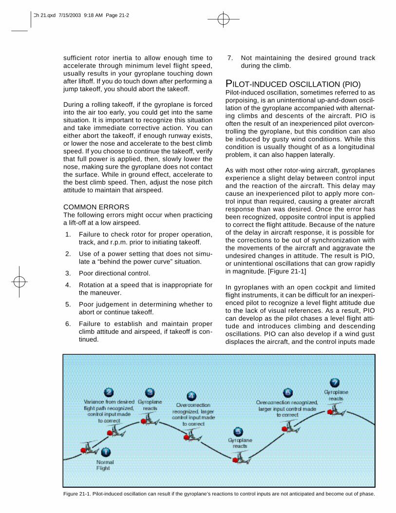
sufficient rotor inertia to allow enough time toaccelerate through minimum level flight speed,usually results in your gyroplane touching downafter liftoff. If you do touch down after performing ajump takeoff, you should abort the takeoff.
During a rolling takeoff, if the gyroplane is forcedinto the air too early, you could get into the samesituation. It is important to recognize this situationand take immediate corrective action. You caneither abort the takeoff, if enough runway exists,or lower the nose and accelerate to the best climbspeed. If you choose to continue the takeoff, verifythat full power is applied, then, slowly lower thenose, making sure the gyroplane does not contactthe surface. While in ground effect, accelerate tothe best climb speed. Then, adjust the nose pitchattitude to maintain that airspeed.
COMMON ERRORSThe following errors might occur when practicinga lift-off at a low airspeed.
1. Failure to check rotor for proper operation,track, and r.p.m. prior to initiating takeoff.
2. Use of a power setting that does not simu-late a “behind the power curve” situation.
3. Poor directional control.
4. Rotation at a speed that is inappropriate forthe maneuver.
5. Poor judgement in determining whether toabort or continue takeoff.
6. Failure to establish and maintain properclimb attitude and airspeed, if takeoff is con-tinued.
7. Not maintaining the desired ground trackduring the climb.
PILOT-INDUCED OSCILLATION (PIO)Pilot-induced oscillation, sometimes referred to asporpoising, is an unintentional up-and-down oscil-lation of the gyroplane accompanied with alternat-ing climbs and descents of the aircraft. PIO isoften the result of an inexperienced pilot overcon-trolling the gyroplane, but this condition can alsobe induced by gusty wind conditions. While thiscondition is usually thought of as a longitudinalproblem, it can also happen laterally.
As with most other rotor-wing aircraft, gyroplanesexperience a slight delay between control inputand the reaction of the aircraft. This delay maycause an inexperienced pilot to apply more con-trol input than required, causing a greater aircraftresponse than was desired. Once the error hasbeen recognized, opposite control input is appliedto correct the flight attitude. Because of the natureof the delay in aircraft response, it is possible forthe corrections to be out of synchronization withthe movements of the aircraft and aggravate theundesired changes in attitude. The result is PIO,or unintentional oscillations that can grow rapidlyin magnitude. [Figure 21-1]
In gyroplanes with an open cockpit and limitedflight instruments, it can be difficult for an inexperi-enced pilot to recognize a level flight attitude dueto the lack of visual references. As a result, PIOcan develop as the pilot chases a level flight atti-tude and introduces climbing and descendingoscillations. PIO can also develop if a wind gustdisplaces the aircraft, and the control inputs made
Figure 21-1. Pilot-induced oscillation can result if the gyroplane’s reactions to control inputs are not anticipated and become out of phase.
Ch 21.qxd 7/15/2003 9:18 AM Page 21-2
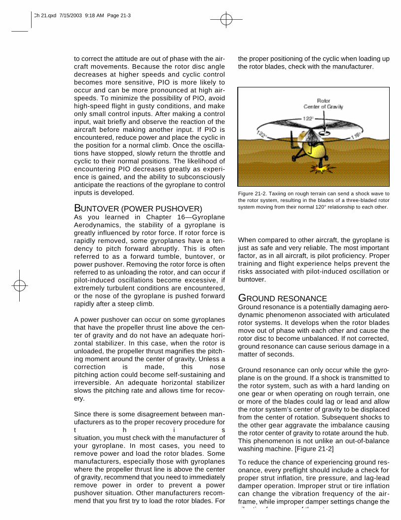
to correct the attitude are out of phase with the air-craft movements. Because the rotor disc angledecreases at higher speeds and cyclic controlbecomes more sensitive, PIO is more likely tooccur and can be more pronounced at high air-speeds. To minimize the possibility of PIO, avoidhigh-speed flight in gusty conditions, and makeonly small control inputs. After making a controlinput, wait briefly and observe the reaction of theaircraft before making another input. If PIO isencountered, reduce power and place the cyclic inthe position for a normal climb. Once the oscilla-tions have stopped, slowly return the throttle andcyclic to their normal positions. The likelihood ofencountering PIO decreases greatly as experi-ence is gained, and the ability to subconsciouslyanticipate the reactions of the gyroplane to controlinputs is developed.
BUNTOVER (POWER PUSHOVER)As you learned in Chapter 16—GyroplaneAerodynamics, the stability of a gyroplane isgreatly influenced by rotor force. If rotor force israpidly removed, some gyroplanes have a ten-dency to pitch forward abruptly. This is oftenreferred to as a forward tumble, buntover, orpower pushover. Removing the rotor force is oftenreferred to as unloading the rotor, and can occur ifpilot-induced oscillations become excessive, ifextremely turbulent conditions are encountered,or the nose of the gyroplane is pushed forwardrapidly after a steep climb.
A power pushover can occur on some gyroplanesthat have the propeller thrust line above the cen-ter of gravity and do not have an adequate hori-zontal stabilizer. In this case, when the rotor isunloaded, the propeller thrust magnifies the pitch-ing moment around the center of gravity. Unless acorrection is made, this nose pitching action could become self-sustaining andirreversible. An adequate horizontal stabilizerslows the pitching rate and allows time for recov-ery.
Since there is some disagreement between man-ufacturers as to the proper recovery procedure fort h i ssituation, you must check with the manufacturer ofyour gyroplane. In most cases, you need toremove power and load the rotor blades. Somemanufacturers, especially those with gyroplaneswhere the propeller thrust line is above the centerof gravity, recommend that you need to immediatelyremove power in order to prevent a powerpushover situation. Other manufacturers recom-mend that you first try to load the rotor blades. For
the proper positioning of the cyclic when loading upthe rotor blades, check with the manufacturer.
When compared to other aircraft, the gyroplane isjust as safe and very reliable. The most importantfactor, as in all aircraft, is pilot proficiency. Propertraining and flight experience helps prevent therisks associated with pilot-induced oscillation orbuntover.
GROUND RESONANCEGround resonance is a potentially damaging aero-dynamic phenomenon associated with articulatedrotor systems. It develops when the rotor bladesmove out of phase with each other and cause therotor disc to become unbalanced. If not corrected,ground resonance can cause serious damage in amatter of seconds.
Ground resonance can only occur while the gyro-plane is on the ground. If a shock is transmitted tothe rotor system, such as with a hard landing onone gear or when operating on rough terrain, oneor more of the blades could lag or lead and allowthe rotor system’s center of gravity to be displacedfrom the center of rotation. Subsequent shocks tothe other gear aggravate the imbalance causingthe rotor center of gravity to rotate around the hub.This phenomenon is not unlike an out-of-balancewashing machine. [Figure 21-2]
To reduce the chance of experiencing ground res-onance, every preflight should include a check forproper strut inflation, tire pressure, and lag-leaddamper operation. Improper strut or tire inflationcan change the vibration frequency of the air-frame, while improper damper settings change thevibration frequency of the rotor.
Figure 21-2. Taxiing on rough terrain can send a shock wave tothe rotor system, resulting in the blades of a three-bladed rotorsystem moving from their normal 120° relationship to each other.
Ch 21.qxd 7/15/2003 9:18 AM Page 21-3
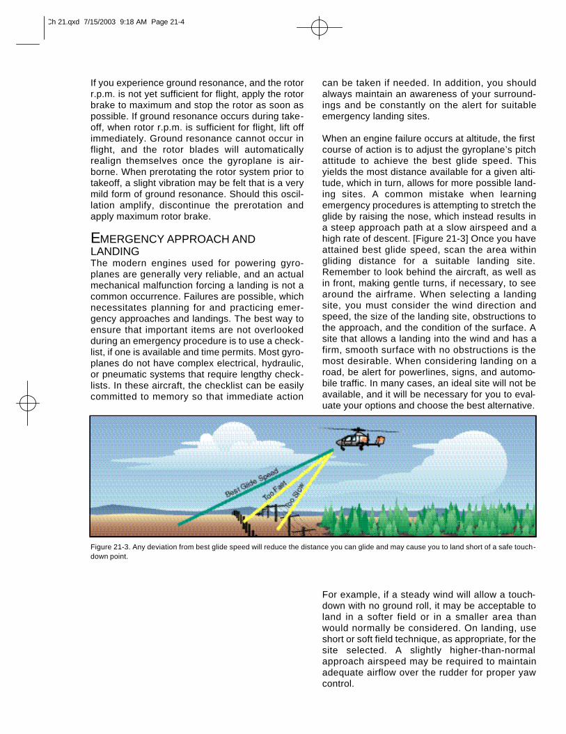
If you experience ground resonance, and the rotorr.p.m. is not yet sufficient for flight, apply the rotorbrake to maximum and stop the rotor as soon aspossible. If ground resonance occurs during take-off, when rotor r.p.m. is sufficient for flight, lift offimmediately. Ground resonance cannot occur inflight, and the rotor blades will automaticallyrealign themselves once the gyroplane is air-borne. When prerotating the rotor system prior totakeoff, a slight vibration may be felt that is a verymild form of ground resonance. Should this oscil-lation amplify, discontinue the prerotation andapply maximum rotor brake.
EMERGENCY APPROACH ANDLANDINGThe modern engines used for powering gyro-planes are generally very reliable, and an actualmechanical malfunction forcing a landing is not acommon occurrence. Failures are possible, whichnecessitates planning for and practicing emer-gency approaches and landings. The best way toensure that important items are not overlookedduring an emergency procedure is to use a check-list, if one is available and time permits. Most gyro-planes do not have complex electrical, hydraulic,or pneumatic systems that require lengthy check-lists. In these aircraft, the checklist can be easilycommitted to memory so that immediate action
can be taken if needed. In addition, you shouldalways maintain an awareness of your surround-ings and be constantly on the alert for suitableemergency landing sites.
When an engine failure occurs at altitude, the firstcourse of action is to adjust the gyroplane’s pitchattitude to achieve the best glide speed. Thisyields the most distance available for a given alti-tude, which in turn, allows for more possible land-ing sites. A common mistake when learningemergency procedures is attempting to stretch theglide by raising the nose, which instead results ina steep approach path at a slow airspeed and ahigh rate of descent. [Figure 21-3] Once you haveattained best glide speed, scan the area withingliding distance for a suitable landing site.Remember to look behind the aircraft, as well asin front, making gentle turns, if necessary, to seearound the airframe. When selecting a landingsite, you must consider the wind direction andspeed, the size of the landing site, obstructions tothe approach, and the condition of the surface. Asite that allows a landing into the wind and has afirm, smooth surface with no obstructions is themost desirable. When considering landing on aroad, be alert for powerlines, signs, and automo-bile traffic. In many cases, an ideal site will not beavailable, and it will be necessary for you to eval-uate your options and choose the best alternative.
For example, if a steady wind will allow a touch-down with no ground roll, it may be acceptable toland in a softer field or in a smaller area thanwould normally be considered. On landing, useshort or soft field technique, as appropriate, for thesite selected. A slightly higher-than-normalapproach airspeed may be required to maintainadequate airflow over the rudder for proper yawcontrol.
Figure 21-3. Any deviation from best glide speed will reduce the distance you can glide and may cause you to land short of a safe touch-down point.
Ch 21.qxd 7/15/2003 9:18 AM Page 21-4
As with any aircraft, the ability to pilot a gyroplanesafely is largely dependent on the capacity of thepilot to make sound and informed decisions. Tothis end, techniques have been developed toensure that a pilot uses a systematic approach tomaking decisions, and that the course of actionselected is the most appropriate for the situation.In addition, it is essential that you learn to evalu-ate your own fitness, just as you evaluate the air-worthiness of your aircraft, to ensure that yourphysical and mental condition is compatible with asafe flight. The techniques for acquiring theseessential skills are explained in depth in Chapter14—Aeronautical Decision Making (Helicopter).
As explained in Chapter 14, one of the best meth-ods to develop your aeronautical decision makingis learning to recognize the five hazardous atti-tudes, and how to counteract these attitudes.[Figure 22-1] This chapter focuses on some exam-
ples of how these hazardous attitudes can applyto gyroplane operations.
IMPULSIVITYGyroplanes are a class of aircraft which can beacquired, constructed, and operated in ways unlikemost other aircraft. This inspires some of the most
exciting and rewarding aspects of flying, but it alsocreates a unique set of dangers to which a gyro-plane pilot must be alert. For example, a wide vari-ety of amateur-built gyroplanes are available,which can be purchased in kit form and assembledat home. This makes the airworthiness of thesegyroplanes ultimately dependent on the vigilanceof the one assembling and maintaining the aircraft.Consider the following scenario.
Jerry recently attended an airshow that had agyroplane flight demonstration and a number ofgyroplanes on display. Being somewhat mechani-cally inclined and retired with available spare time,Jerry decided that building a gyroplane would bean excellent project for him and ordered a kit thatday. When the kit arrived, Jerry unpacked it in hisgarage and immediately began the assembly. Asthe gyroplane neared completion, Jerry grewmore excited at the prospect of flying an aircraftthat he had built with his own hands. When thegyroplane was nearly complete, Jerry noticed thata rudder cable was missing from the kit, or per-haps lost during the assembly. Rather than con-tacting the manufacturer and ordering areplacement, which Jerry thought would be a has-sle and too time consuming, he went to his localhardware store and purchased some cable hethought would work. Upon returning home, he wasable to fashion a rudder cable that seemed func-tional and continued with the assembly.
Jerry is exhibiting “impulsivity.” Rather than takingthe time to properly build his gyroplane to thespecifications set forth by the manufacturer, Jerrylet his excitement allow him to cut corners by acting onimpulse, rather than taking the time to think thematter through. Although some enthusiasm is nor-mal during assembly, it should not be permitted tocompromise the airworthiness of the aircraft.Manufacturers often use high quality components,which are constructed and tested to standardsmuch higher than those found in hardware stores.This is particularly true in the area of cables, bolts,nuts, and other types of fasteners where strengthis essential. The proper course of action Jerryshould have taken would be to stop, think, andconsider the possible consequences of making an
Figure 22-1. To overcome hazardous attitudes, you must memo-rize the antidotes for each of them. You should know them so wellthat they will automatically come to mind when you need them.
Ch 22.qxd 7/15/2003 9:19 AM Page 22-1
impulsive decision. Had he realized that a broken rudder cable in flight could cause a loss of controlof the gyroplane, he likely would have taken thetime to contact the manufacturer and order a cablethat met the design specifications.
INVULNERABILITYAnother area that can often lead to trouble for agyroplane pilots is the failure to obtain adequateflight instruction to operate their gyroplane safely.This can be the result of people thinking thatbecause they can build the machine themselves,it must be simple enough to learn how to fly bythemselves. Other reasons that can lead to this problem can be sim-ply monetary, in not wanting to pay the money foradequate instruction, or feeling that because theyare qualified in another type of aircraft, flightinstruction is not necessary. In reality, gyroplaneoperations are quite unique, and there is no sub-stitute for adequate training by a competent andauthorized instructor. Consider the following scenario.
Jim recently met a coworker who is a certified pilotand owner of a two-seat gyroplane. In discussingthe gyroplane with his coworker, Jim was fasci-nated and reminded of his days in the military as ahelicopter pilot many years earlier. When offereda ride, Jim readily accepted. He met his coworkerat the airport the following weekend for a short flight and wasimmediately hooked. After spending severalweeks researching available designs, Jim decidedon a particular gyroplane and purchased a kit. He had it assem-bled in a few months, with the help and advice ofhis new friend and fellow gyroplane enthusiast.When the gyroplane was finally finished, Jimasked his friend to take him for a ride in his two-seater to teach him the basics of flying. The rest,he said, he would figure out while flying his own machine from a landing strip that hehad fashioned in a field behind his house.
Jim is unknowingly inviting disaster by allowinghimself to be influenced by the hazardous attitudeof “invulnerability.” Jim does not feel that it is pos-sible to have an accident, probably because of hispast experience in helicopters and from witness-ing the ease with which his coworker controlledthe gyroplane on their flight together. What Jim isfailing to consider, however, is the amount of timethat has passed since he was proficient in helicop-ters, and the significant differences between heli-copter and gyroplane operations. He is alsooverlooking the fact that his friend is a certificated
pilot, who has taken a considerable amount ofinstruction to reach his level of competence.Without adequate instruction and experience, Jimcould, for example, find himself in a pilot-inducedoscillation without knowing the proper techniquefor recovery, which could ultimately be disastrous.The antidote for an attitude of invulnerability is to realize that acci-dents can happen to anyone.
MACHODue to their unique design, gyroplanes are quiteresponsive and have distinct capabilities.Although gyroplanes are capable of incrediblemaneuvers, they do have limitations. As gyroplanepilots grow more comfortable with their machines,they might be tempted to operate progressivelycloser to the edge of the safe operating envelope.Consider the following scenario.
Pat has been flying gyroplanes for years and hasan excellent reputation as a skilled pilot. He hasrecently built a high performance gyroplane withan advanced rotor system. Pat was excited tomove into a more advanced aircraft because hehad seen the same design performing aerobaticsin an airshow earlier that year. He was amazed bythe capability of the machine. He had always feltthat his ability surpassed the capability of the air-craft he was flying. He had invested a largeamount of time and resources into the construc-tion of the aircraft, and, as he neared completionof the assembly, he was excited about the oppor-tunity of showing his friends and family his capa-bilities.
During the first few flights, Pat was not completelycomfortable in the new aircraft, but he felt that hewas progressing through the transition at a muchfaster pace than the average pilot. One morning,when he was with some of his fellow gyroplaneenthusiasts, Pat began to brag about the superiorhandling qualities of the machine he had built. Hisfriends were very excited, and Pat realized thatthey would be expecting quite a show on his nextflight. Not wanting to disappoint them, he decidedthat although it might be early, he would give thespectators on the ground a real show. On his firstpass he came down fairly steep and fast andrecovered from the dive with ease. Pat thendecided to make another pass only this time hewould come in much steeper. As he began torecover, the aircraft did not climb as he expectedand almost settled to the ground. Pat narrowlyescaped hitting the spectators as he was trying to recover from the dive.
Ch 22.qxd 7/15/2003 9:19 AM Page 22-2
Pat had let the “macho” hazardous attitude influ-ence his decision making. He could have avoidedthe consequences of this attitude if he hadstopped to think that taking chances is foolish.
RESIGNATIONSome of the elements pilots face cannot be con-trolled. Although we cannot control the weather,we do have some very good tools to help predictwhat it will do, and how it can affect our ability tofly safely. Good pilots always make decisions thatwill keep their options open if an unexpectedevent occurs while flying. One of the greatest resources we have inthe cockpit is the ability to improvise and improvethe overall situation even when a risk elementjeopardizes the probability of a successful flight.Consider the following scenario.
Judi flies her gyroplane out of a small grass stripon her family’s ranch. Although the rugged land-scape of the ranch lends itself to the remarkablescenery, it leaves few places to safely land in theevent of an emergency. The only suitable place toland other than the grass strip is to the west on asmooth section of the road leading to the house.
During Judi’s training, her traffic patterns werealways made with left turns. Figuring this was howshe was to make all traffic patterns, she appliedthis to the grass strip at the ranch. In addition, shewas uncomfortable with making turns to the right.Since, the wind at the ranch was predominatelyfrom the south, this meant that the traffic patternwas to the east of the strip.
Judi’s hazardous attitude is “resignation.” She hasaccepted the fact that her only course of action isto fly east of the strip, and if an emergency hap-pens, there is not much she can do about it. Theantidote to this hazardous attitude is “I’m not helpless, I can makea difference.” Judi could easily modify her trafficpattern so that she is always within gliding distanceof a suitable landing area. In addition, if she wasuncomfortable with a maneuver, she could getadditional training.
ANTI-AUTHORITYRegulations are implemented to protect aviation personnel as well as the people who are notinvolved in aviation. Pilots who choose to operateoutside of the regulations, or on the ragged edge,eventually get caught, or even worse, they end uphaving an accident. Consider the following sce-nario.
Dick is planning to fly the following morning andrealizes that his medical certificate has expired.He knows that he will not have time to take a flightphysical before his morning flight. Dick thinks tohimself “The rules are too restrictive. Why should Ispend the time and money on a physical when Iwill be the only one at risk if I fly tomorrow?”
Dick decides to fly the next morning thinking thatno harm will come as long as no one finds out thathe is flying illegally. He pulls his gyroplane outfrom the hangar, does the preflight inspection, andis getting ready to start the engine when an FAAinspector walks up and greets him. The FAAinspector is conducting a random inspection andasks to see Dick’s pilot and medical certificates.
Dick subjected himself to the hazardous attitude of“anti-authority.” Now, he will be unable to fly, andhas invited an exhaustive review of his operation bythe FAA. Dick could have prevented this event ifhad taken the time to think, “Follow the rules. Theyare usually right.”
Ch 22.qxd 7/15/2003 9:19 AM Page 22-3