Embed Size (px)
Citation preview

GX-6000Operator’s Manual
Part Number: 71-0362
Revision: F
Released: 11/6/17
www.rkiinstruments.com
WARNING
Read and understand this instruction manual before operating instrument. Improper use of the gas monitor could result in bodily harm or death.
Periodic calibration and maintenance of the gas monitor is essential for proper operation and correct readings. Please calibrate and maintain this instrument regularly! Frequency of calibration depends upon the type of use you have and the sensor types. Typical calibration frequencies for most applications are between 1 and 3 months, but can be required more often or less often based on your usage.
GX-6000 Operator’s Manual
Table of Contents
Chapter 1: Introduction . . . . . . . . . . . . . . . . . . . . . . . . . . . . . . . . . . . 1Overview . . . . . . . . . . . . . . . . . . . . . . . . . . . . . . . . . . . . . . . . . . . . . . . . . . . . 1About the GX-6000 . . . . . . . . . . . . . . . . . . . . . . . . . . . . . . . . . . . . . . . . . . . . 1Specifications . . . . . . . . . . . . . . . . . . . . . . . . . . . . . . . . . . . . . . . . . . . . . . . . 3About this Manual . . . . . . . . . . . . . . . . . . . . . . . . . . . . . . . . . . . . . . . . . . . . . 6
Chapter 2: Description . . . . . . . . . . . . . . . . . . . . . . . . . . . . . . . . . . . . 7Overview . . . . . . . . . . . . . . . . . . . . . . . . . . . . . . . . . . . . . . . . . . . . . . . . . . . . 7Instrument Description . . . . . . . . . . . . . . . . . . . . . . . . . . . . . . . . . . . . . . . . . 7
Case . . . . . . . . . . . . . . . . . . . . . . . . . . . . . . . . . . . . . . . . . . . . . . . . . . 7LCD . . . . . . . . . . . . . . . . . . . . . . . . . . . . . . . . . . . . . . . . . . . . . . . . . . . 8Control Buttons . . . . . . . . . . . . . . . . . . . . . . . . . . . . . . . . . . . . . . . . . . 8Flashlight LED . . . . . . . . . . . . . . . . . . . . . . . . . . . . . . . . . . . . . . . . . . 8Alarm LEDs . . . . . . . . . . . . . . . . . . . . . . . . . . . . . . . . . . . . . . . . . . . . 9Infrared Communications Port . . . . . . . . . . . . . . . . . . . . . . . . . . . . . . 9Buzzer . . . . . . . . . . . . . . . . . . . . . . . . . . . . . . . . . . . . . . . . . . . . . . . . . 9Vibrator . . . . . . . . . . . . . . . . . . . . . . . . . . . . . . . . . . . . . . . . . . . . . . . . 9Printed Circuit Boards (PCBs) . . . . . . . . . . . . . . . . . . . . . . . . . . . . . . 9Pump . . . . . . . . . . . . . . . . . . . . . . . . . . . . . . . . . . . . . . . . . . . . . . . . . . 9Flow Chamber . . . . . . . . . . . . . . . . . . . . . . . . . . . . . . . . . . . . . . . . . . . 9Sensors . . . . . . . . . . . . . . . . . . . . . . . . . . . . . . . . . . . . . . . . . . . . . . . . 10Filters. . . . . . . . . . . . . . . . . . . . . . . . . . . . . . . . . . . . . . . . . . . . . . . . . 11Inlet Filter Holder . . . . . . . . . . . . . . . . . . . . . . . . . . . . . . . . . . . . . . . 11Batteries . . . . . . . . . . . . . . . . . . . . . . . . . . . . . . . . . . . . . . . . . . . . . . . 12
Included Accessories . . . . . . . . . . . . . . . . . . . . . . . . . . . . . . . . . . . . . . . . . . 13Tapered Rubber Nozzle . . . . . . . . . . . . . . . . . . . . . . . . . . . . . . . . . . . 13Belt Clip . . . . . . . . . . . . . . . . . . . . . . . . . . . . . . . . . . . . . . . . . . . . . . . 13Rubber Boot . . . . . . . . . . . . . . . . . . . . . . . . . . . . . . . . . . . . . . . . . . . . 13Wrist Strap . . . . . . . . . . . . . . . . . . . . . . . . . . . . . . . . . . . . . . . . . . . . . 13Sample Hose and Probe. . . . . . . . . . . . . . . . . . . . . . . . . . . . . . . . . . . 13Screen Protector . . . . . . . . . . . . . . . . . . . . . . . . . . . . . . . . . . . . . . . . 14
Other Accessories . . . . . . . . . . . . . . . . . . . . . . . . . . . . . . . . . . . . . . . . . . . . 15VOC Zero Filter . . . . . . . . . . . . . . . . . . . . . . . . . . . . . . . . . . . . . . . . . 15External Dilution Fitting . . . . . . . . . . . . . . . . . . . . . . . . . . . . . . . . . 16DIN Rail Mounting Assembly . . . . . . . . . . . . . . . . . . . . . . . . . . . . . . 16
GX-6000 Operator’s Manual Table of Contents
Chapter 3: Operation . . . . . . . . . . . . . . . . . . . . . . . . . . . . . . . . . . . . . 19Overview . . . . . . . . . . . . . . . . . . . . . . . . . . . . . . . . . . . . . . . . . . . . . . . . . . . 19Start Up . . . . . . . . . . . . . . . . . . . . . . . . . . . . . . . . . . . . . . . . . . . . . . . . . . . . 19
Turning On the GX-6000 . . . . . . . . . . . . . . . . . . . . . . . . . . . . . . . . . 19Performing a Demand Zero . . . . . . . . . . . . . . . . . . . . . . . . . . . . . . . 28Turning Off the GX-6000 . . . . . . . . . . . . . . . . . . . . . . . . . . . . . . . . . 29
Measuring Mode, Normal Operation . . . . . . . . . . . . . . . . . . . . . . . . . . . . . 29Monitoring an Area . . . . . . . . . . . . . . . . . . . . . . . . . . . . . . . . . . . . . . 30Using Optional Sample Hoses . . . . . . . . . . . . . . . . . . . . . . . . . . . . . 31Combustible Gas Detection . . . . . . . . . . . . . . . . . . . . . . . . . . . . . . . 31VOC Detection . . . . . . . . . . . . . . . . . . . . . . . . . . . . . . . . . . . . . . . . . . 33Oxygen Detection. . . . . . . . . . . . . . . . . . . . . . . . . . . . . . . . . . . . . . . . 33Snap Log Mode . . . . . . . . . . . . . . . . . . . . . . . . . . . . . . . . . . . . . . . . . 34
Measuring Mode, Alarms . . . . . . . . . . . . . . . . . . . . . . . . . . . . . . . . . . . . . . 36Alarm Indications . . . . . . . . . . . . . . . . . . . . . . . . . . . . . . . . . . . . . . . 36Responding to Alarms . . . . . . . . . . . . . . . . . . . . . . . . . . . . . . . . . . . . 38
Display Mode . . . . . . . . . . . . . . . . . . . . . . . . . . . . . . . . . . . . . . . . . . . . . . . 43Tips for Using Display Mode . . . . . . . . . . . . . . . . . . . . . . . . . . . . . . 44PID Gas Name Screen . . . . . . . . . . . . . . . . . . . . . . . . . . . . . . . . . . . . 45Peak Screen . . . . . . . . . . . . . . . . . . . . . . . . . . . . . . . . . . . . . . . . . . . . 47STEL Screen. . . . . . . . . . . . . . . . . . . . . . . . . . . . . . . . . . . . . . . . . . . . 48TWA Screen . . . . . . . . . . . . . . . . . . . . . . . . . . . . . . . . . . . . . . . . . . . . 48View Alarm Settings Screen . . . . . . . . . . . . . . . . . . . . . . . . . . . . . . . . 49Time in Operation Screen . . . . . . . . . . . . . . . . . . . . . . . . . . . . . . . . . 51Date/Time, Battery Voltage Screen . . . . . . . . . . . . . . . . . . . . . . . . . . 51Log Time Remaining Screen . . . . . . . . . . . . . . . . . . . . . . . . . . . . . . . 52Clear Data Logging Screen . . . . . . . . . . . . . . . . . . . . . . . . . . . . . . . . 52Pump Off Screen . . . . . . . . . . . . . . . . . . . . . . . . . . . . . . . . . . . . . . . . 54Select User ID Screen . . . . . . . . . . . . . . . . . . . . . . . . . . . . . . . . . . . . 55Select Station ID Screen. . . . . . . . . . . . . . . . . . . . . . . . . . . . . . . . . . . 57Viewing Snap Logger Data . . . . . . . . . . . . . . . . . . . . . . . . . . . . . . . . 59Peak Bar Screen. . . . . . . . . . . . . . . . . . . . . . . . . . . . . . . . . . . . . . . . . 60Gas Display Screen . . . . . . . . . . . . . . . . . . . . . . . . . . . . . . . . . . . . . . 61LCD Flip Screen . . . . . . . . . . . . . . . . . . . . . . . . . . . . . . . . . . . . . . . . 62Combustible Sensor Protection Screen . . . . . . . . . . . . . . . . . . . . . . . 63LCD Background Color Flip Screen . . . . . . . . . . . . . . . . . . . . . . . . . 64Language Screen . . . . . . . . . . . . . . . . . . . . . . . . . . . . . . . . . . . . . . . . 65
Table of Contents GX-6000 Operator’s Manual
Data Logging . . . . . . . . . . . . . . . . . . . . . . . . . . . . . . . . . . . . . . . . . . . . . . . . 66
Chapter 4: Calibration Mode . . . . . . . . . . . . . . . . . . . . . . . . . . . . . . 68Overview . . . . . . . . . . . . . . . . . . . . . . . . . . . . . . . . . . . . . . . . . . . . . . . . . . . 68Calibration Supplies and Equipment . . . . . . . . . . . . . . . . . . . . . . . . . . . . . . 69Entering Calibration Mode . . . . . . . . . . . . . . . . . . . . . . . . . . . . . . . . . . . . . 70Calibrating Using the Auto Calibration Method . . . . . . . . . . . . . . . . . . . . . 71
Setting the Fresh Air Reading . . . . . . . . . . . . . . . . . . . . . . . . . . . . . . 71Performing a Span Adjustment . . . . . . . . . . . . . . . . . . . . . . . . . . . . . 74Returning to Measuring Mode. . . . . . . . . . . . . . . . . . . . . . . . . . . . . . 83
Calibrating Using the Single Calibration Method . . . . . . . . . . . . . . . . . . . . 84Setting the Fresh Air Reading . . . . . . . . . . . . . . . . . . . . . . . . . . . . . . 84Performing a Span Adjustment in Single Calibration . . . . . . . . . . . 86
Performing a Bump Test . . . . . . . . . . . . . . . . . . . . . . . . . . . . . . . . . . . . . . . 90
Chapter 5: User Mode . . . . . . . . . . . . . . . . . . . . . . . . . . . . . . . . . . . . 96Overview . . . . . . . . . . . . . . . . . . . . . . . . . . . . . . . . . . . . . . . . . . . . . . . . . . . 96Tips for Using User Mode . . . . . . . . . . . . . . . . . . . . . . . . . . . . . . . . . . . . . . 96Entering User Mode . . . . . . . . . . . . . . . . . . . . . . . . . . . . . . . . . . . . . . . . . . . 97Setting the Date and Time . . . . . . . . . . . . . . . . . . . . . . . . . . . . . . . . . . . . . . 98Setting the Date Format . . . . . . . . . . . . . . . . . . . . . . . . . . . . . . . . . . . . . . . . 99Configuring the Channels . . . . . . . . . . . . . . . . . . . . . . . . . . . . . . . . . . . . . . 99Updating the Language Setting . . . . . . . . . . . . . . . . . . . . . . . . . . . . . . . . . 101Viewing the ROM/SUM of the Instrument . . . . . . . . . . . . . . . . . . . . . . . . 101Turning the Password Function On or Off. . . . . . . . . . . . . . . . . . . . . . . . . 102Exiting User Mode . . . . . . . . . . . . . . . . . . . . . . . . . . . . . . . . . . . . . . . . . . . 103
Chapter 6: Maintenance . . . . . . . . . . . . . . . . . . . . . . . . . . . . . . . . . 104Overview . . . . . . . . . . . . . . . . . . . . . . . . . . . . . . . . . . . . . . . . . . . . . . . . . . 104Troubleshooting . . . . . . . . . . . . . . . . . . . . . . . . . . . . . . . . . . . . . . . . . . . . 104Replacing or Recharging the Batteries . . . . . . . . . . . . . . . . . . . . . . . . . . . 106
Replacing the Alkaline Batteries . . . . . . . . . . . . . . . . . . . . . . . . . . . 106Replacing the Lithium Ion Battery Pack . . . . . . . . . . . . . . . . . . . . . 108Recharging the Lithium Ion Battery Pack . . . . . . . . . . . . . . . . . . . . 110Recharging the Lithium Ion Battery Pack Out of the Instrument . . 112
Replacing the Probe’s Particle Filter and Hydrophobic Filter Disk . . . . . 115Replacing the H2S Scrubber Disk and the Charcoal Filter . . . . . . . . . . . . 117
GX-6000 Operator’s Manual Table of Contents
Replacing a Sensor . . . . . . . . . . . . . . . . . . . . . . . . . . . . . . . . . . . . . . . . . . 120Replacing the Hydrophobic Filter and Wire Mesh Disk . . . . . . . . . . . . . . 123PID Sensor Maintenance . . . . . . . . . . . . . . . . . . . . . . . . . . . . . . . . . . . . . . 124
Cleaning the PID Sensor’s Lamp . . . . . . . . . . . . . . . . . . . . . . . . . . 124Replacing the PID Sensor’s Lamp. . . . . . . . . . . . . . . . . . . . . . . . . . 129Replacing the PID Sensor’s Electrode Stack. . . . . . . . . . . . . . . . . . 133
General Parts List . . . . . . . . . . . . . . . . . . . . . . . . . . . . . . . . . . . . . . . . . . . 137
Appendix A: Maintenance Mode . . . . . . . . . . . . . . . . . . . . . . . . . . 140Overview . . . . . . . . . . . . . . . . . . . . . . . . . . . . . . . . . . . . . . . . . . . . . . . . . . 140Tips for Using Maintenance Mode . . . . . . . . . . . . . . . . . . . . . . . . . . . . . . 144Using Maintenance Mode . . . . . . . . . . . . . . . . . . . . . . . . . . . . . . . . . . . . . 144
Setting the Date and Time . . . . . . . . . . . . . . . . . . . . . . . . . . . . . . . . 147Setting the Date Format . . . . . . . . . . . . . . . . . . . . . . . . . . . . . . . . . 148Performing a Calibration . . . . . . . . . . . . . . . . . . . . . . . . . . . . . . . . 148Performing a Bump Test . . . . . . . . . . . . . . . . . . . . . . . . . . . . . . . . . 148Updating Calibration Settings . . . . . . . . . . . . . . . . . . . . . . . . . . . . . 149Updating Bump Test Settings . . . . . . . . . . . . . . . . . . . . . . . . . . . . . . 151Updating Alarm Parameters . . . . . . . . . . . . . . . . . . . . . . . . . . . . . . 156Turning the Pump On/Off Display On or Off . . . . . . . . . . . . . . . . . 159Turning the User/Station ID Function On or Off . . . . . . . . . . . . . . 160Updating the Backlight Time Setting . . . . . . . . . . . . . . . . . . . . . . . . 160Updating the Language Setting . . . . . . . . . . . . . . . . . . . . . . . . . . . . 160Updating the Lunch Break Setting. . . . . . . . . . . . . . . . . . . . . . . . . . 161Updating the Auto Zero Setting . . . . . . . . . . . . . . . . . . . . . . . . . . . . 161Updating the Demand Zero Setting . . . . . . . . . . . . . . . . . . . . . . . . . 162Zero Follower Setting . . . . . . . . . . . . . . . . . . . . . . . . . . . . . . . . . . . 162Zero Suppression Settings . . . . . . . . . . . . . . . . . . . . . . . . . . . . . . . . 162Updating the Autoranging Setting . . . . . . . . . . . . . . . . . . . . . . . . . . 162Updating the Confirmation Alert Setting. . . . . . . . . . . . . . . . . . . . . 163Turning the Key Tone Noise On or Off . . . . . . . . . . . . . . . . . . . . . . 164Turning Inert Mode On or Off . . . . . . . . . . . . . . . . . . . . . . . . . . . . . 164Updating the Leak Check/Bar Hole Mode Setting. . . . . . . . . . . . . . 164Setting the Bar Hole Measurement Time . . . . . . . . . . . . . . . . . . . . . 165Updating the CO Display Setting . . . . . . . . . . . . . . . . . . . . . . . . . . 165Updating the Man Down Settings . . . . . . . . . . . . . . . . . . . . . . . . . . 166Updating the Datalogging Parameters . . . . . . . . . . . . . . . . . . . . . . 168Adjusting the Low Flow Setpoint . . . . . . . . . . . . . . . . . . . . . . . . . . . 170
Table of Contents GX-6000 Operator’s Manual
Viewing the ROM/SUM of the Instrument . . . . . . . . . . . . . . . . . . . . 171Turning the Password Function On or Off . . . . . . . . . . . . . . . . . . . 171Restoring the Default Settings . . . . . . . . . . . . . . . . . . . . . . . . . . . . . 172Exiting Maintenance Mode . . . . . . . . . . . . . . . . . . . . . . . . . . . . . . . 174
Appendix B: Maintenance Mode 2 . . . . . . . . . . . . . . . . . . . . . . . . . 175Overview . . . . . . . . . . . . . . . . . . . . . . . . . . . . . . . . . . . . . . . . . . . . . . . . . . 175Tips for Using Maintenance Mode 2 . . . . . . . . . . . . . . . . . . . . . . . . . . . . . 175Using Maintenance Mode 2 . . . . . . . . . . . . . . . . . . . . . . . . . . . . . . . . . . . . 176
Changing the Gas Combination . . . . . . . . . . . . . . . . . . . . . . . . . . . 178Changing the Catalytic LEL Channel’s Target Gas . . . . . . . . . . . . 179Exiting Maintenance Mode 2. . . . . . . . . . . . . . . . . . . . . . . . . . . . . . 179
Appendix C: ESS-03 Toxic Sensors . . . . . . . . . . . . . . . . . . . . . . . . . 180Overview . . . . . . . . . . . . . . . . . . . . . . . . . . . . . . . . . . . . . . . . . . . . . . . . . . 180Description . . . . . . . . . . . . . . . . . . . . . . . . . . . . . . . . . . . . . . . . . . . . . . . . . 180Interference . . . . . . . . . . . . . . . . . . . . . . . . . . . . . . . . . . . . . . . . . . . . . . . . 181Start Up and Normal Operation . . . . . . . . . . . . . . . . . . . . . . . . . . . . . . . . . 182ESS-03 Calibration . . . . . . . . . . . . . . . . . . . . . . . . . . . . . . . . . . . . . . . . . . 183
Calibrating the ESS-03 Sensor Using Auto Calibration . . . . . . . . . 183Calibrating the ESS-03 Sensor Using Single Calibration. . . . . . . . 189
ESS-03 Bump Testing . . . . . . . . . . . . . . . . . . . . . . . . . . . . . . . . . . . . . . . . 190Replacing the ESS-03 Sensor or Changing Sensor Type. . . . . . . . . . . . . . 190Parts List . . . . . . . . . . . . . . . . . . . . . . . . . . . . . . . . . . . . . . . . . . . . . . . . . . 191
Appendix D: IR Sensors . . . . . . . . . . . . . . . . . . . . . . . . . . . . . . . . . . 193Overview . . . . . . . . . . . . . . . . . . . . . . . . . . . . . . . . . . . . . . . . . . . . . . . . . . 193
IR HC Target Gases . . . . . . . . . . . . . . . . . . . . . . . . . . . . . . . . . . . . . 193IR CH4 Target Gases . . . . . . . . . . . . . . . . . . . . . . . . . . . . . . . . . . . . 193
Description . . . . . . . . . . . . . . . . . . . . . . . . . . . . . . . . . . . . . . . . . . . . . . . . . 194IR Sensor . . . . . . . . . . . . . . . . . . . . . . . . . . . . . . . . . . . . . . . . . . . . . 194CO2 Scrubber . . . . . . . . . . . . . . . . . . . . . . . . . . . . . . . . . . . . . . . . . 195
IR HC Start Up and Normal Operation . . . . . . . . . . . . . . . . . . . . . . . . . . . 1990 - 100 %LEL/2.0 - 30.0 %vol Autoranging . . . . . . . . . . . . . . . . . . 196
IR CH4 Start Up and Normal Operation . . . . . . . . . . . . . . . . . . . . . . . . . . 1960 - 100 %LEL/5.0 - 100.0 %vol Autoranging . . . . . . . . . . . . . . . . . 196
IR CO2 Start Up and Normal Operation . . . . . . . . . . . . . . . . . . . . . . . . . . 197Performing a Demand Zero for Carbon Dioxide Sensors . . . . . . . . 197
GX-6000 Operator’s Manual Table of Contents
IR Calibration. . . . . . . . . . . . . . . . . . . . . . . . . . . . . . . . . . . . . . . . . . . . . . . 199IR Bump Testing . . . . . . . . . . . . . . . . . . . . . . . . . . . . . . . . . . . . . . . . . . . . 199Replacing an IR Sensor . . . . . . . . . . . . . . . . . . . . . . . . . . . . . . . . . . . . . . . 200Parts List . . . . . . . . . . . . . . . . . . . . . . . . . . . . . . . . . . . . . . . . . . . . . . . . . . 201
Appendix E: Using the GX-6000 in Leak Check Mode. . . . . . . . . 203Overview . . . . . . . . . . . . . . . . . . . . . . . . . . . . . . . . . . . . . . . . . . . . . . . . . . 203Start Up, Leak Check Mode. . . . . . . . . . . . . . . . . . . . . . . . . . . . . . . . . . . . 203
Turning On the GX-6000, Leak Check Mode . . . . . . . . . . . . . . . . . 203Performing a Demand Zero, Leak Check Mode . . . . . . . . . . . . . . . 205
Leak Testing . . . . . . . . . . . . . . . . . . . . . . . . . . . . . . . . . . . . . . . . . . . . . . . . 206Setting the Display Range Value . . . . . . . . . . . . . . . . . . . . . . . . . . . 206Turning the Alarm On and Off . . . . . . . . . . . . . . . . . . . . . . . . . . . . . 206Locating a Leak . . . . . . . . . . . . . . . . . . . . . . . . . . . . . . . . . . . . . . . . 207Overscale Conditions. . . . . . . . . . . . . . . . . . . . . . . . . . . . . . . . . . . . 207Peak Hold Mode . . . . . . . . . . . . . . . . . . . . . . . . . . . . . . . . . . . . . . . 208Snap Log Mode, Leak Check Mode Operation . . . . . . . . . . . . . . . . 208Viewing Snap Log Data in Leak Check Mode . . . . . . . . . . . . . . . . . 211Turning Off the GX-6000, Leak Check Mode . . . . . . . . . . . . . . . . . 214
Appendix F: Using the GX-6000 in Bar Hole Mode . . . . . . . . . . . 215Overview . . . . . . . . . . . . . . . . . . . . . . . . . . . . . . . . . . . . . . . . . . . . . . . . . . 215Start Up, Bar Hole Mode . . . . . . . . . . . . . . . . . . . . . . . . . . . . . . . . . . . . . . 216
Turning on the GX-6000, Bar Hole Mode . . . . . . . . . . . . . . . . . . . . 216Performing a Fresh Air Adjustment, Bar Hole Mode . . . . . . . . . . . 218
Bar Hole Testing . . . . . . . . . . . . . . . . . . . . . . . . . . . . . . . . . . . . . . . . . . . . 219Performing a Bar Hole Test. . . . . . . . . . . . . . . . . . . . . . . . . . . . . . . 219Turning Off the GX-6000, Bar Hole Mode . . . . . . . . . . . . . . . . . . . 222
Appendix G: Using the GX-6000 in Inert Mode . . . . . . . . . . . . . . 223Alarms . . . . . . . . . . . . . . . . . . . . . . . . . . . . . . . . . . . . . . . . . . . . . . . . . . . . 223Start Up and Operation . . . . . . . . . . . . . . . . . . . . . . . . . . . . . . . . . . . . . . . 224
Appendix H: 10.0 eV/Benzene PID Sensor. . . . . . . . . . . . . . . . . . . 226Overview . . . . . . . . . . . . . . . . . . . . . . . . . . . . . . . . . . . . . . . . . . . . . . . . . . 226Sensor Description . . . . . . . . . . . . . . . . . . . . . . . . . . . . . . . . . . . . . . . . . . . 227
Table of Contents GX-6000 Operator’s Manual
Tube and Tube Holder . . . . . . . . . . . . . . . . . . . . . . . . . . . . . . . . . . . . . . . . 227Tube . . . . . . . . . . . . . . . . . . . . . . . . . . . . . . . . . . . . . . . . . . . . . . . . . . . . Tube Holder . . . . . . . . . . . . . . . . . . . . . . . . . . . . . . . . . . . . . . . . . . . 228
Start Up . . . . . . . . . . . . . . . . . . . . . . . . . . . . . . . . . . . . . . . . . . . . . . . . . . . 228Display Mode. . . . . . . . . . . . . . . . . . . . . . . . . . . . . . . . . . . . . . . . . . . . . . . 229Measuring Mode . . . . . . . . . . . . . . . . . . . . . . . . . . . . . . . . . . . . . . . . . . . . 230Benzene Select Mode. . . . . . . . . . . . . . . . . . . . . . . . . . . . . . . . . . . . . . . . . 230Viewing Benzene Select Mode Data . . . . . . . . . . . . . . . . . . . . . . . . . . . . . 236Calibrating the 10.0 eV/Benzene PID Sensor . . . . . . . . . . . . . . . . . . . . . . 239
Important Calibration Information . . . . . . . . . . . . . . . . . . . . . . . . . 239Performing an AUTO CAL . . . . . . . . . . . . . . . . . . . . . . . . . . . . . . . 240Performing a SINGLE CAL . . . . . . . . . . . . . . . . . . . . . . . . . . . . . . . 241Performing a TUBE CAL. . . . . . . . . . . . . . . . . . . . . . . . . . . . . . . . . 241Entering a CAL CODE . . . . . . . . . . . . . . . . . . . . . . . . . . . . . . . . . . 248
Maintenance . . . . . . . . . . . . . . . . . . . . . . . . . . . . . . . . . . . . . . . . . . . . . . . . 250PID Sensor Maintenance . . . . . . . . . . . . . . . . . . . . . . . . . . . . . . . . . 250Replacing a Tube . . . . . . . . . . . . . . . . . . . . . . . . . . . . . . . . . . . . . . . 250
Parts List . . . . . . . . . . . . . . . . . . . . . . . . . . . . . . . . . . . . . . . . . . . . . . . . . . 252
WARNING: Understand manual before operating. Substitution of components may impair intrinsic safety. To prevent ignition of a hazardous atmosphere, batteries must only be changed or charged in an area known to be nonhazardous. Not tested in oxygen enriched atmospheres (above 21%).
NOTE: RKI Instruments, Inc. recommends that you refer to ISA-RP12.13, Part II-1987 or an equivalent international recommended practice for guidance in the use of combustible gas detection instruments.
GX-6000 Operator’s Manual Table of Contents
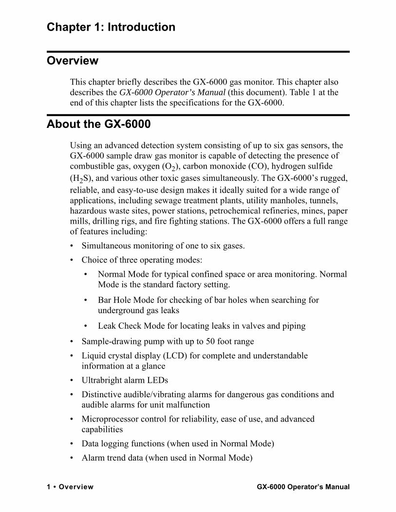
Chapter 1: Introduction
OverviewThis chapter briefly describes the GX-6000 gas monitor. This chapter also describes the GX-6000 Operator’s Manual (this document). Table 1 at the end of this chapter lists the specifications for the GX-6000.
About the GX-6000Using an advanced detection system consisting of up to six gas sensors, the GX-6000 sample draw gas monitor is capable of detecting the presence of combustible gas, oxygen (O2), carbon monoxide (CO), hydrogen sulfide (H2S), and various other toxic gases simultaneously. The GX-6000’s rugged, reliable, and easy-to-use design makes it ideally suited for a wide range of applications, including sewage treatment plants, utility manholes, tunnels, hazardous waste sites, power stations, petrochemical refineries, mines, paper mills, drilling rigs, and fire fighting stations. The GX-6000 offers a full range of features including:• Simultaneous monitoring of one to six gases. • Choice of three operating modes:
• Normal Mode for typical confined space or area monitoring. Normal Mode is the standard factory setting.
• Bar Hole Mode for checking of bar holes when searching for underground gas leaks
• Leak Check Mode for locating leaks in valves and piping
• Sample-drawing pump with up to 50 foot range• Liquid crystal display (LCD) for complete and understandable
information at a glance• Ultrabright alarm LEDs• Distinctive audible/vibrating alarms for dangerous gas conditions and
audible alarms for unit malfunction• Microprocessor control for reliability, ease of use, and advanced
capabilities • Data logging functions (when used in Normal Mode)• Alarm trend data (when used in Normal Mode)
1 • Overview GX-6000 Operator’s Manual
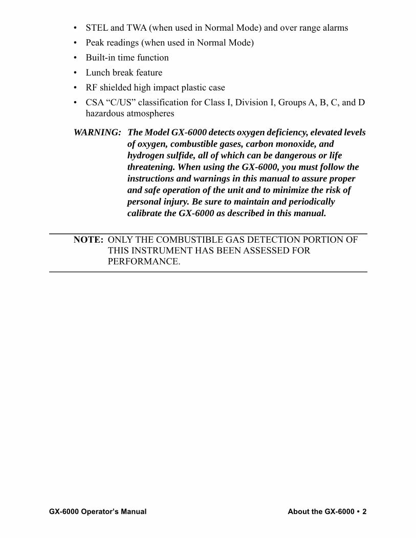
• STEL and TWA (when used in Normal Mode) and over range alarms• Peak readings (when used in Normal Mode)• Built-in time function• Lunch break feature• RF shielded high impact plastic case• CSA “C/US” classification for Class I, Division I, Groups A, B, C, and D
hazardous atmospheres
WARNING: The Model GX-6000 detects oxygen deficiency, elevated levels of oxygen, combustible gases, carbon monoxide, and hydrogen sulfide, all of which can be dangerous or life threatening. When using the GX-6000, you must follow the instructions and warnings in this manual to assure proper and safe operation of the unit and to minimize the risk of personal injury. Be sure to maintain and periodically calibrate the GX-6000 as described in this manual.
NOTE: ONLY THE COMBUSTIBLE GAS DETECTION PORTION OF THIS INSTRUMENT HAS BEEN ASSESSED FOR PERFORMANCE.
GX-6000 Operator’s Manual About the GX-6000 • 2
n
PID
DeR
m
ReInc
:
pm:
AlFacto
*
AlFacto
STE
TW
* When l to or highe if nece
** Altho
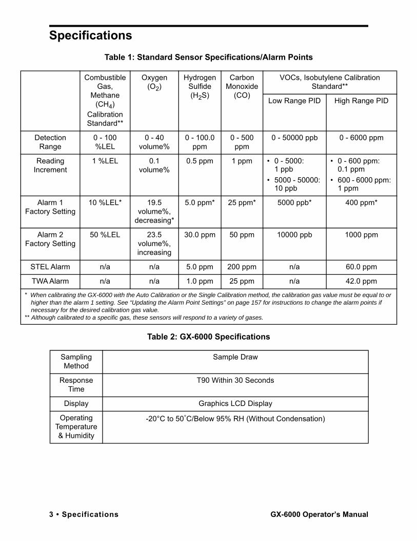
SpecificationsTable 1: Standard Sensor Specifications/Alarm Points
Table 2: GX-6000 Specifications
Combustible Gas,
Methane (CH4)
Calibration Standard**
Oxygen (O2)
Hydrogen Sulfide (H2S)
Carbon Monoxide
(CO)
VOCs, Isobutylene CalibratioStandard**
Low Range PID High Range
tection ange
0 - 100 %LEL
0 - 40 volume%
0 - 100.0 ppm
0 - 500 ppm
0 - 50000 ppb 0 - 6000 pp
ading rement
1 %LEL 0.1 volume%
0.5 ppm 1 ppm • 0 - 5000: 1 ppb
• 5000 - 50000: 10 ppb
• 0 - 600 ppm0.1 ppm
• 600 - 6000 p1 ppm
arm 1ry Setting
10 %LEL* 19.5 volume%,
decreasing*
5.0 ppm* 25 ppm* 5000 ppb* 400 ppm
arm 2ry Setting
50 %LEL 23.5 volume%, increasing
30.0 ppm 50 ppm 10000 ppb 1000 ppm
L Alarm n/a n/a 5.0 ppm 200 ppm n/a 60.0 ppm
A Alarm n/a n/a 1.0 ppm 25 ppm n/a 42.0 ppm
calibrating the GX-6000 with the Auto Calibration or the Single Calibration method, the calibration gas value must be equar than the alarm 1 setting. See “Updating the Alarm Point Settings” on page 157 for instructions to change the alarm pointsssary for the desired calibration gas value.ugh calibrated to a specific gas, these sensors will respond to a variety of gases.
Sampling Method
Sample Draw
Response Time
T90 Within 30 Seconds
Display Graphics LCD Display
Operating Temperature & Humidity
-20°C to 50°C/Below 95% RH (Without Condensation)
3 • Specifications GX-6000 Operator’s Manual
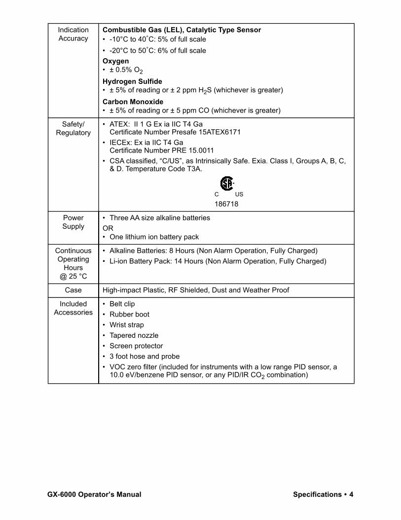
Indication Accuracy
Combustible Gas (LEL), Catalytic Type Sensor• -10°C to 40°C: 5% of full scale• -20°C to 50°C: 6% of full scaleOxygen• ± 0.5% O2
Hydrogen Sulfide• ± 5% of reading or ± 2 ppm H2S (whichever is greater)Carbon Monoxide• ± 5% of reading or ± 5 ppm CO (whichever is greater)
Safety/Regulatory
• ATEX: II 1 G Ex ia IIC T4 GaCertificate Number Presafe 15ATEX6171
• IECEx: Ex ia IIC T4 GaCertificate Number PRE 15.0011
• CSA classified, “C/US”, as Intrinsically Safe. Exia. Class I, Groups A, B, C, & D. Temperature Code T3A.
C US
186718
Power Supply
• Three AA size alkaline batteriesOR• One lithium ion battery pack
Continuous Operating
Hours@ 25 °C
• Alkaline Batteries: 8 Hours (Non Alarm Operation, Fully Charged)• Li-ion Battery Pack: 14 Hours (Non Alarm Operation, Fully Charged)
Case High-impact Plastic, RF Shielded, Dust and Weather Proof
Included Accessories
• Belt clip• Rubber boot• Wrist strap• Tapered nozzle• Screen protector• 3 foot hose and probe• VOC zero filter (included for instruments with a low range PID sensor, a
10.0 eV/benzene PID sensor, or any PID/IR CO2 combination)
GX-6000 Operator’s Manual Specifications • 4
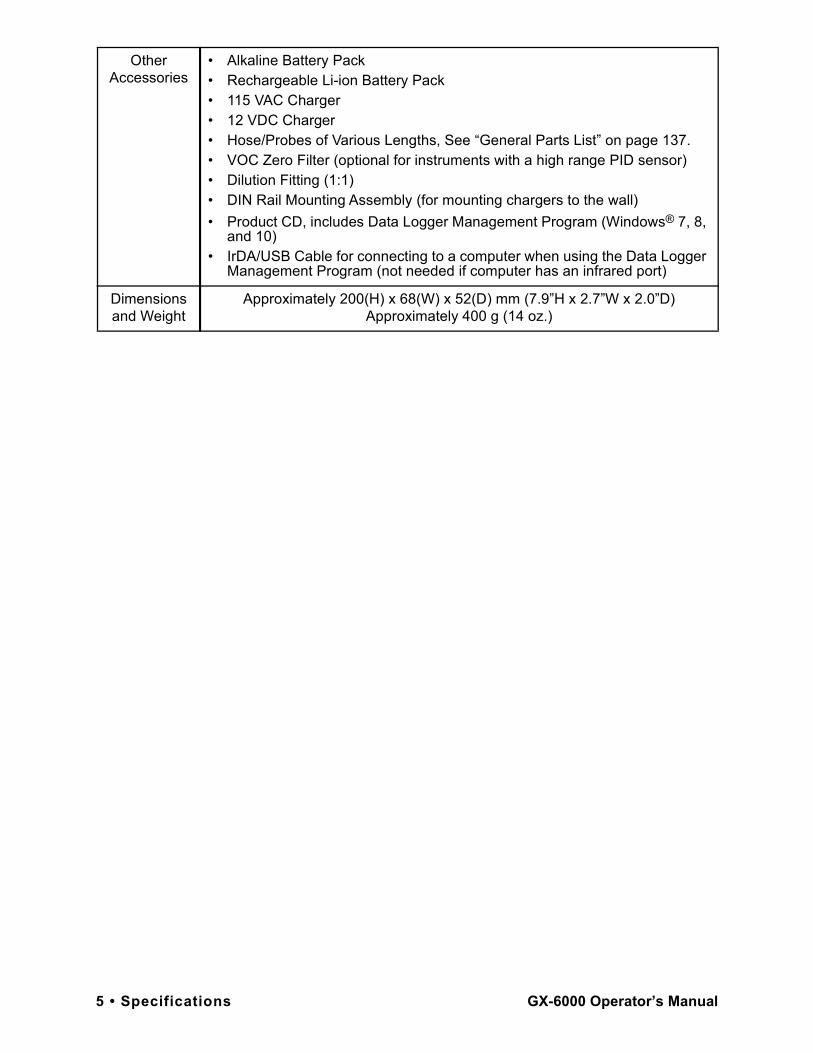
Other Accessories
• Alkaline Battery Pack• Rechargeable Li-ion Battery Pack• 115 VAC Charger• 12 VDC Charger• Hose/Probes of Various Lengths, See “General Parts List” on page 137.• VOC Zero Filter (optional for instruments with a high range PID sensor)• Dilution Fitting (1:1)• DIN Rail Mounting Assembly (for mounting chargers to the wall)• Product CD, includes Data Logger Management Program (Windows® 7, 8,
and 10)• IrDA/USB Cable for connecting to a computer when using the Data Logger
Management Program (not needed if computer has an infrared port)
Dimensions and Weight
Approximately 200(H) x 68(W) x 52(D) mm (7.9”H x 2.7”W x 2.0”D)Approximately 400 g (14 oz.)
5 • Specifications GX-6000 Operator’s Manual
About this ManualAlthough the GX-6000 can support up to 6 sensors, this manual specifically describes an instrument with the four standard sensors and a PID sensor. See the appendices for descriptions of other sensors.The GX-6000 Operator’s Manual uses the following conventions for notes, cautions, and warnings.
NOTE: Describes additional or critical information.
CAUTION: Describes potential damage to equipment.
WARNING: Describes potential danger that can result in injury or death.
The GX-6000 Operator’s Manual is organized as follows:• Chapter 1 is an introduction to the GX-6000.• Chapter 2 describes the components of the GX-6000.• Chapter 3 describes the operation of the GX-6000.• Chapter 4 describes Calibration Mode which allows you to calibrate the
GX-6000’s active channels.• Chapter 5 describes the GX-6000’s User Mode.• Chapter 6 describes the GX-6000’s maintenance requirements and
procedures.• Appendix A describes Maintenance Mode which allows you to configure
different parameters of the GX-6000.• Appendix B describes Maintenance Mode 2 which allows you to change
the GAS COMB and HC SELECT parameters.• Appendix C describes the ESS-03 sensors and the operation of the GX-
6000 with an ESS-03 sensor installed.• Appendix D describes the IR sensors and the operation of the GX-6000
with an IR sensor installed.• Appendix E describes the operation of the GX-6000 in Leak Check
Mode.• Appendix F describes the operation of the GX-6000 in Bar Hole Mode.• Appendix G describes the operation of the GX-6000 in Inert Mode.• Appendix H describes the 10.0 eV/benzene PID sensor.
GX-6000 Operator’s Manual About this Manual • 6
Chapter 2: Description
OverviewThis chapter describes the GX-6000 instrument and accessories.
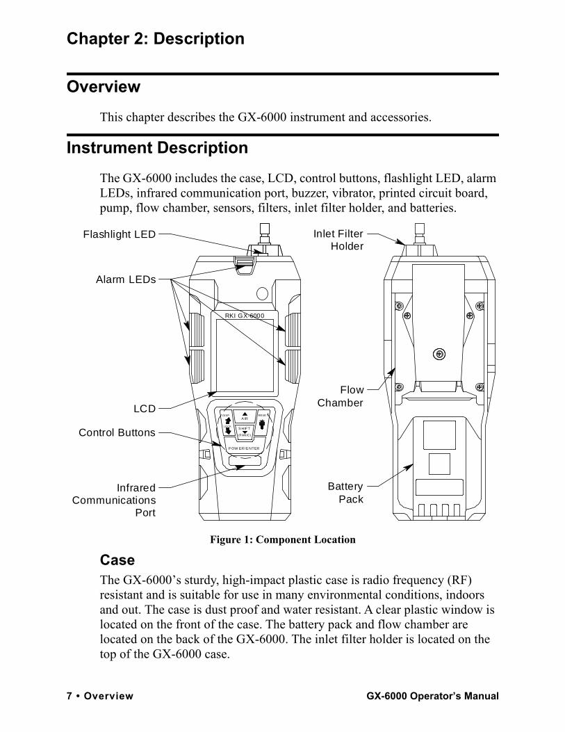
Instrument DescriptionThe GX-6000 includes the case, LCD, control buttons, flashlight LED, alarm LEDs, infrared communication port, buzzer, vibrator, printed circuit board, pump, flow chamber, sensors, filters, inlet filter holder, and batteries.
Figure 1: Component Location
CaseThe GX-6000’s sturdy, high-impact plastic case is radio frequency (RF) resistant and is suitable for use in many environmental conditions, indoors and out. The case is dust proof and water resistant. A clear plastic window is located on the front of the case. The battery pack and flow chamber are located on the back of the GX-6000. The inlet filter holder is located on the top of the GX-6000 case.
Inlet FilterHolder
FlowChamber
BatteryPack
Flashlight LED
Alarm LEDs
RKI GX-6000
DISP
LOCK
(PANIC)
A IR
S HIFT
RESE T
InfraredCommunications
Port
Control Buttons
LCD
P OW ER/E NTER
7 • Overview GX-6000 Operator’s Manual
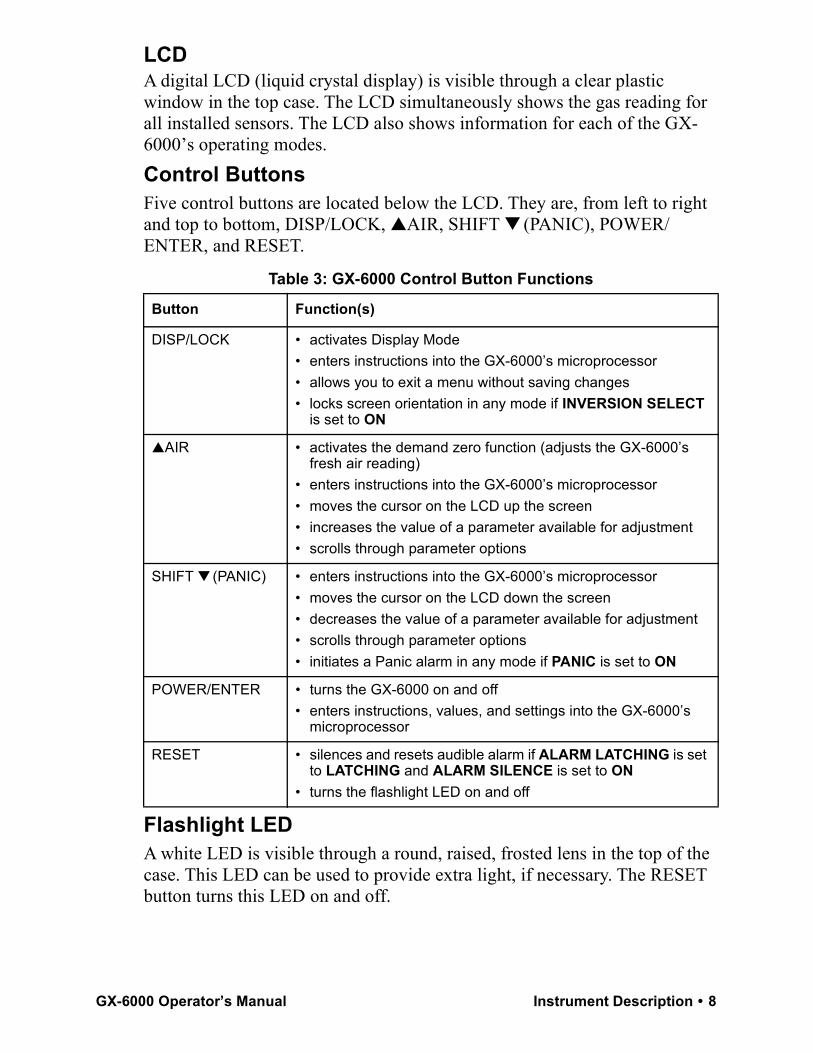
LCDA digital LCD (liquid crystal display) is visible through a clear plastic window in the top case. The LCD simultaneously shows the gas reading for all installed sensors. The LCD also shows information for each of the GX-6000’s operating modes.Control ButtonsFive control buttons are located below the LCD. They are, from left to right and top to bottom, DISP/LOCK, ▲AIR, SHIFT ▼ (PANIC), POWER/ENTER, and RESET.
Flashlight LEDA white LED is visible through a round, raised, frosted lens in the top of the case. This LED can be used to provide extra light, if necessary. The RESET button turns this LED on and off.
Table 3: GX-6000 Control Button Functions
Button Function(s)
DISP/LOCK • activates Display Mode• enters instructions into the GX-6000’s microprocessor• allows you to exit a menu without saving changes• locks screen orientation in any mode if INVERSION SELECT
is set to ON
▲AIR • activates the demand zero function (adjusts the GX-6000’s fresh air reading)
• enters instructions into the GX-6000’s microprocessor• moves the cursor on the LCD up the screen• increases the value of a parameter available for adjustment• scrolls through parameter options
SHIFT ▼ (PANIC) • enters instructions into the GX-6000’s microprocessor• moves the cursor on the LCD down the screen• decreases the value of a parameter available for adjustment• scrolls through parameter options• initiates a Panic alarm in any mode if PANIC is set to ON
POWER/ENTER • turns the GX-6000 on and off• enters instructions, values, and settings into the GX-6000’s
microprocessor
RESET • silences and resets audible alarm if ALARM LATCHING is set to LATCHING and ALARM SILENCE is set to ON
• turns the flashlight LED on and off
GX-6000 Operator’s Manual Instrument Description • 8
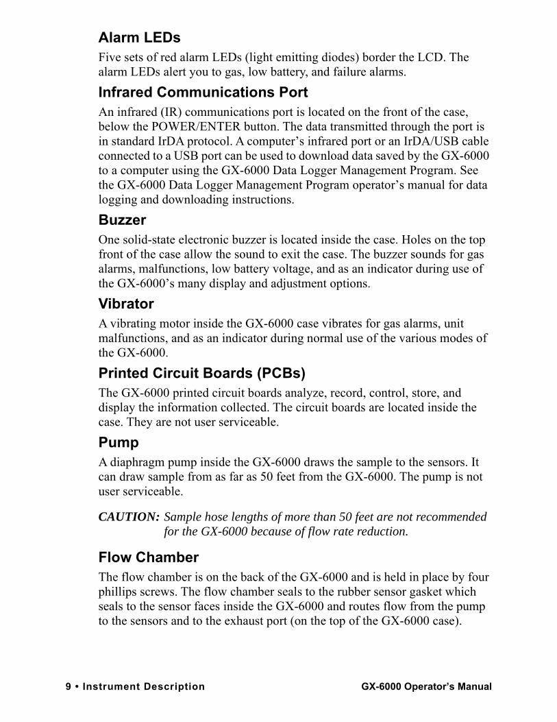
Alarm LEDsFive sets of red alarm LEDs (light emitting diodes) border the LCD. The alarm LEDs alert you to gas, low battery, and failure alarms.Infrared Communications PortAn infrared (IR) communications port is located on the front of the case, below the POWER/ENTER button. The data transmitted through the port is in standard IrDA protocol. A computer’s infrared port or an IrDA/USB cable connected to a USB port can be used to download data saved by the GX-6000 to a computer using the GX-6000 Data Logger Management Program. See the GX-6000 Data Logger Management Program operator’s manual for data logging and downloading instructions.BuzzerOne solid-state electronic buzzer is located inside the case. Holes on the top front of the case allow the sound to exit the case. The buzzer sounds for gas alarms, malfunctions, low battery voltage, and as an indicator during use of the GX-6000’s many display and adjustment options.VibratorA vibrating motor inside the GX-6000 case vibrates for gas alarms, unit malfunctions, and as an indicator during normal use of the various modes of the GX-6000.Printed Circuit Boards (PCBs)The GX-6000 printed circuit boards analyze, record, control, store, and display the information collected. The circuit boards are located inside the case. They are not user serviceable.PumpA diaphragm pump inside the GX-6000 draws the sample to the sensors. It can draw sample from as far as 50 feet from the GX-6000. The pump is not user serviceable.
CAUTION: Sample hose lengths of more than 50 feet are not recommended for the GX-6000 because of flow rate reduction.
Flow ChamberThe flow chamber is on the back of the GX-6000 and is held in place by four phillips screws. The flow chamber seals to the rubber sensor gasket which seals to the sensor faces inside the GX-6000 and routes flow from the pump to the sensors and to the exhaust port (on the top of the GX-6000 case).
9 • Instrument Description GX-6000 Operator’s Manual
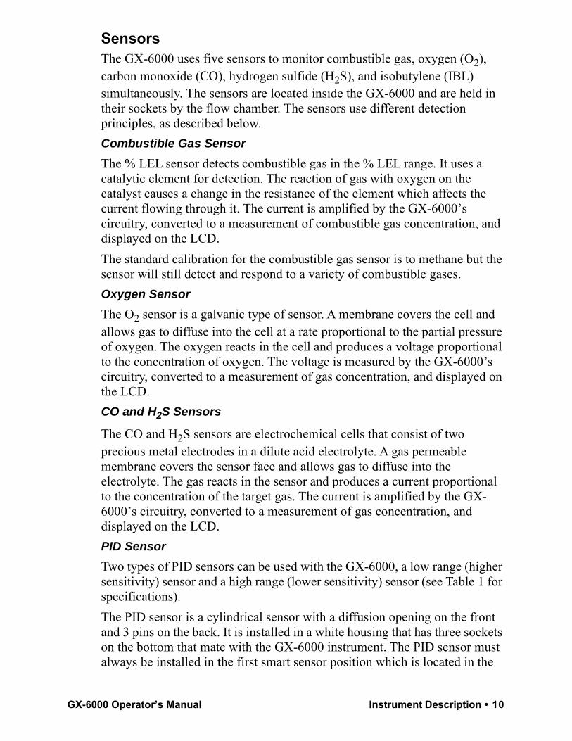
SensorsThe GX-6000 uses five sensors to monitor combustible gas, oxygen (O2), carbon monoxide (CO), hydrogen sulfide (H2S), and isobutylene (IBL) simultaneously. The sensors are located inside the GX-6000 and are held in their sockets by the flow chamber. The sensors use different detection principles, as described below.Combustible Gas SensorThe % LEL sensor detects combustible gas in the % LEL range. It uses a catalytic element for detection. The reaction of gas with oxygen on the catalyst causes a change in the resistance of the element which affects the current flowing through it. The current is amplified by the GX-6000’s circuitry, converted to a measurement of combustible gas concentration, and displayed on the LCD.The standard calibration for the combustible gas sensor is to methane but the sensor will still detect and respond to a variety of combustible gases.Oxygen SensorThe O2 sensor is a galvanic type of sensor. A membrane covers the cell and allows gas to diffuse into the cell at a rate proportional to the partial pressure of oxygen. The oxygen reacts in the cell and produces a voltage proportional to the concentration of oxygen. The voltage is measured by the GX-6000’s circuitry, converted to a measurement of gas concentration, and displayed on the LCD.CO and H2S Sensors
The CO and H2S sensors are electrochemical cells that consist of two precious metal electrodes in a dilute acid electrolyte. A gas permeable membrane covers the sensor face and allows gas to diffuse into the electrolyte. The gas reacts in the sensor and produces a current proportional to the concentration of the target gas. The current is amplified by the GX-6000’s circuitry, converted to a measurement of gas concentration, and displayed on the LCD.PID SensorTwo types of PID sensors can be used with the GX-6000, a low range (higher sensitivity) sensor and a high range (lower sensitivity) sensor (see Table 1 for specifications). The PID sensor is a cylindrical sensor with a diffusion opening on the front and 3 pins on the back. It is installed in a white housing that has three sockets on the bottom that mate with the GX-6000 instrument. The PID sensor must always be installed in the first smart sensor position which is located in the
GX-6000 Operator’s Manual Instrument Description • 10
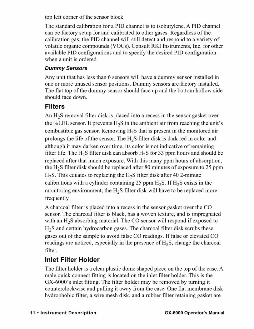
top left corner of the sensor block.The standard calibration for a PID channel is to isobutylene. A PID channel can be factory setup for and calibrated to other gases. Regardless of the calibration gas, the PID channel will still detect and respond to a variety of volatile organic compounds (VOCs). Consult RKI Instruments, Inc. for other available PID configurations and to specify the desired PID configuration when a unit is ordered. Dummy SensorsAny unit that has less than 6 sensors will have a dummy sensor installed in one or more unused sensor positions. Dummy sensors are factory installed. The flat top of the dummy sensor should face up and the bottom hollow side should face down.FiltersAn H2S removal filter disk is placed into a recess in the sensor gasket over the %LEL sensor. It prevents H2S in the ambient air from reaching the unit’s combustible gas sensor. Removing H2S that is present in the monitored air prolongs the life of the sensor. The H2S filter disk is dark red in color and although it may darken over time, its color is not indicative of remaining filter life. The H2S filter disk can absorb H2S for 33 ppm hours and should be replaced after that much exposure. With this many ppm hours of absorption, the H2S filter disk should be replaced after 80 minutes of exposure to 25 ppm H2S. This equates to replacing the H2S filter disk after 40 2-minute calibrations with a cylinder containing 25 ppm H2S. If H2S exists in the monitoring environment, the H2S filter disk will have to be replaced more frequently.A charcoal filter is placed into a recess in the sensor gasket over the CO sensor. The charcoal filter is black, has a woven texture, and is impregnated with an H2S absorbing material. The CO sensor will respond if exposed to H2S and certain hydrocarbon gases. The charcoal filter disk scrubs these gases out of the sample to avoid false CO readings. If false or elevated CO readings are noticed, especially in the presence of H2S, change the charcoal filter.Inlet Filter HolderThe filter holder is a clear plastic dome shaped piece on the top of the case. A male quick connect fitting is located on the inlet filter holder. This is the GX-6000’s inlet fitting. The filter holder may be removed by turning it counterclockwise and pulling it away from the case. One flat membrane disk hydrophobic filter, a wire mesh disk, and a rubber filter retaining gasket are
11 • Instrument Description GX-6000 Operator’s Manual
held in place by the filter holder and are located in the bottom of the case chamber where the filter holder is installed.BatteriesThree AA-size alkaline batteries or a rechargeable lithium ion battery pack (4.1 VDC) power the GX-6000. Instrument run time is dependent upon battery type. At 25°C the alkaline batteries last at least 8 hours and the lithium ion battery pack lasts at least 14 hours. The battery icon in the upper right of the LCD shows remaining battery life.When the GX-6000 detects a low battery voltage, a low battery warning is activated. When battery voltage is too low for Measuring Mode, the GX-6000 sounds a dead battery alarm. The alkaline batteries can be replaced by removing the battery cover on the back of the case. The lithium ion pack can be replaced by removing the entire battery pack. The battery pack release latch is located on the bottom of the instrument. When viewing the instrument from the bottom with the LCD facing down, push the battery pack release latch toward the right to release the pack.The lithium ion battery pack can be recharged by placing the GX-6000 in its battery charging station or by placing the battery pack in the charging station.
NOTE: Use of batteries or battery chargers not specified by RKI Instruments, Inc. will compromise the CSA classification and may void the warranty. See “Replacing or Recharging the Batteries” on page 106.
WARNING: To prevent ignition of a hazardous atmosphere, batteries must only be changed or charged in an area known to be nonhazardous.
AVERTISSEMENT:Pour éviter l’inflammation d’une atmosphère dangereuse, les batteries doivent uniquement être modifiés ou facturés dans une zone connue comme non dangereuse.
GX-6000 Operator’s Manual Instrument Description • 12
Included AccessoriesIncluded accessories consist of the tapered rubber nozzle, belt clip, rubber boot, wrist strap, and the sample hose/probe.Tapered Rubber NozzleA cone shaped 4 inch long rubber nozzle is included with the GX-6000 as standard. It can be installed on the inlet fitting by pushing the larger end over it. The smaller end can be inserted through a hole in a wall or some other access to an enclosed area to sample the environment.Belt ClipA belt clip can be mounted to the back of the case using 3 phillips head screws. The belt clip allows the GX-6000 to be securely attached to a belt.Rubber BootA protective rubber boot can be installed over the GX-6000.Wrist StrapA wrist strap is included with the GX-6000 and can be attached to the right or left wrist strap installation feature on the GX-6000 case. Sample Hose and ProbeA 3 foot sample hose with an attached probe is standard with the GX-6000. When desired, the rubber nozzle may be removed and the sample hose and probe may be connected to the inlet fitting. Sample hose lengths are available from 3 feet to 50 feet (see “General Parts List” on page 137). The quick connect end of the sample hose connects to the inlet fitting of the GX-6000. The probe is integral with the hose and connects to it with a tube fitting.
CAUTION: Sample hose lengths of more than 50 feet are not recommended for the GX-6000 because of flow rate reduction.
The probe includes a replaceable particle filter and hydrophobic filter disk that prevent particulates and water from entering the GX-6000’s flow system. See “Replacing the Probe’s Particle Filter and Hydrophobic Filter Disk” on page 115 for instructions to replace the particle filter and hydrophobic filter disk.
13 • Included Accessories GX-6000 Operator’s Manual

Figure 2: Sample Hose and Probe
Screen ProtectorThe clear screen protector can be installed over the GX-6000’s LCD to prevent it from getting scratched.1 . Remove the GX-6000’s rubber boot.2 . Orient the GX-6000 so that the LCD is as horizontal as possible.3 . Clean the LCD with rubbing alcohol.4 . Place 1 drop of water in the center of the LCD.5 . Grasp the tab at the top of the screen protector’s backing and pull it away
from the screen protector.6 . Use needle-nose pliers or tweezers to handle the screen protector.7 . Align the top of the screen protector with the top of the “RKI GX-6000”
logo.8 . Press down on the center of the screen protector. Water should spread out
along the entire surface of the screen protector between the screen protector and the LCD. Some of the water may come out the edges.
9 . If you are unhappy with the initial placement of the screen protector, lift the screen protector up from a corner. Quickly rearrange the screen protector and set it back down on the LCD.
10 . Use a small, stiff piece of plastic and, working your way out from center, remove any air bubbles. The screen protector may shift during this process so be sure to hold it securely with your other hand.
11 . Allow enough time for the water between the screen protector and the LCD to dry before handling the GX-6000.
GX-6000 Operator’s Manual Included Accessories • 14
12 . Reinstall the rubber boot.
Other AccessoriesSeveral other accessories are available for the GX-6000. This section describes the VOC zero filter, the dilution fitting, and the DIN rail. Detailed instructions regarding the use of the dilution fitting are included in other parts of this manual. Data logging accessories are briefly described in “Data Logging” on page 66. VOC Zero FilterA VOC zero filter is included as standard with GX-6000s that include:• Low range PID sensor (PID-001L)• 10.0 eV/benzene PID sensor (PID-003L)• Any PID sensor and any CO2 sensor
The VOC zero filter scrubs out low levels of VOC gases using charcoal. Use the VOC zero filter when:• Performing an air adjust on a PID sensor in an area that may have a low-
level VOC background. • Performing an air adjust on a PID/CO2 instrument (in combination with a
CO2 scrubber).
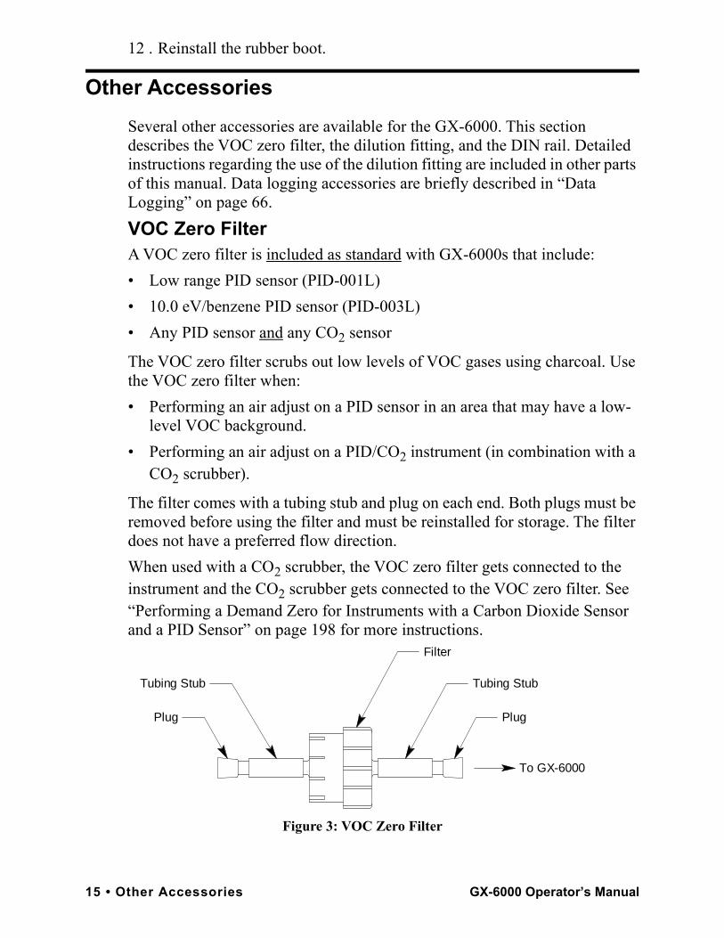
The filter comes with a tubing stub and plug on each end. Both plugs must be removed before using the filter and must be reinstalled for storage. The filter does not have a preferred flow direction.When used with a CO2 scrubber, the VOC zero filter gets connected to the instrument and the CO2 scrubber gets connected to the VOC zero filter. See “Performing a Demand Zero for Instruments with a Carbon Dioxide Sensor and a PID Sensor” on page 198 for more instructions.
Figure 3: VOC Zero Filter
Filter
Plug
Tubing StubTubing Stub
Plug
To GX-6000
15 • Other Accessories GX-6000 Operator’s Manual
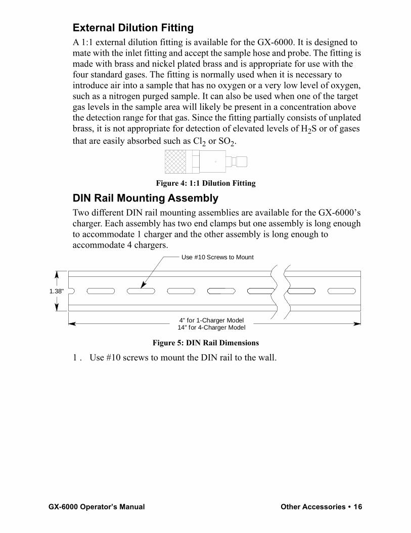
External Dilution FittingA 1:1 external dilution fitting is available for the GX-6000. It is designed to mate with the inlet fitting and accept the sample hose and probe. The fitting is made with brass and nickel plated brass and is appropriate for use with the four standard gases. The fitting is normally used when it is necessary to introduce air into a sample that has no oxygen or a very low level of oxygen, such as a nitrogen purged sample. It can also be used when one of the target gas levels in the sample area will likely be present in a concentration above the detection range for that gas. Since the fitting partially consists of unplated brass, it is not appropriate for detection of elevated levels of H2S or of gases that are easily absorbed such as Cl2 or SO2.
Figure 4: 1:1 Dilution Fitting
DIN Rail Mounting AssemblyTwo different DIN rail mounting assemblies are available for the GX-6000’s charger. Each assembly has two end clamps but one assembly is long enough to accommodate 1 charger and the other assembly is long enough to accommodate 4 chargers.
Figure 5: DIN Rail Dimensions
1 . Use #10 screws to mount the DIN rail to the wall.
4" for 1-Charger Model14" for 4-Charger Model
Use #10 Screws to Mount
1.38"
GX-6000 Operator’s Manual Other Accessories • 16
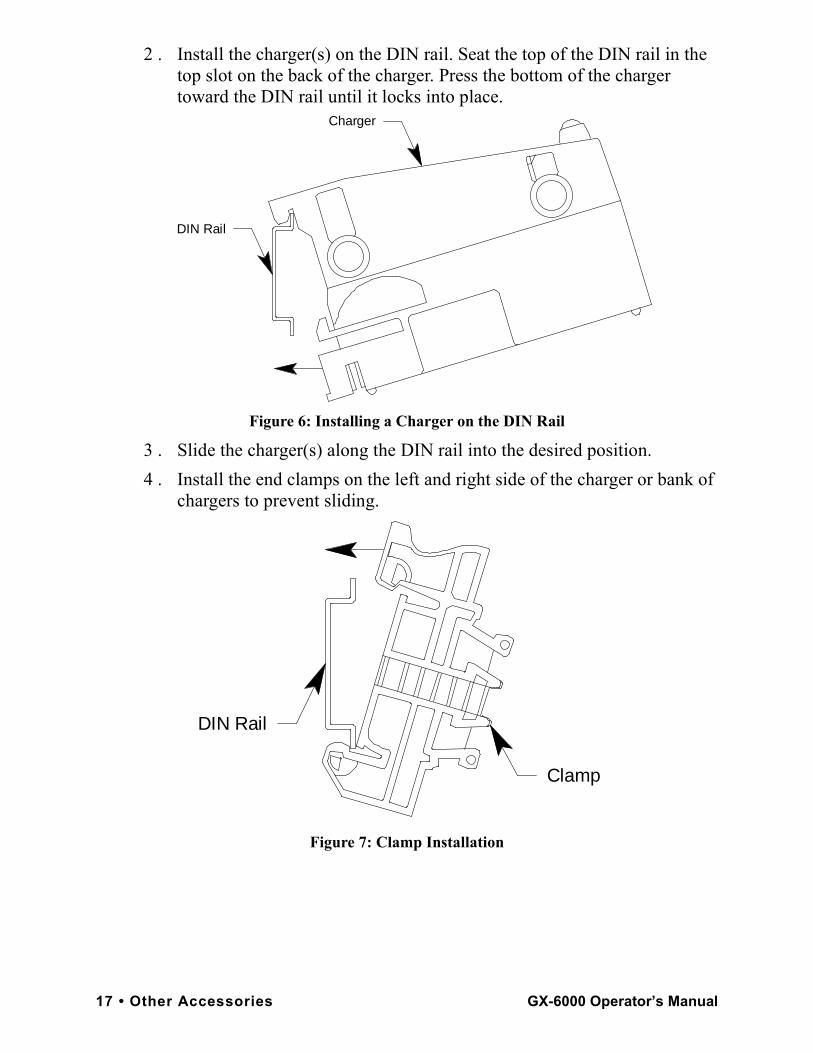
2 . Install the charger(s) on the DIN rail. Seat the top of the DIN rail in the top slot on the back of the charger. Press the bottom of the charger toward the DIN rail until it locks into place.
Figure 6: Installing a Charger on the DIN Rail
3 . Slide the charger(s) along the DIN rail into the desired position. 4 . Install the end clamps on the left and right side of the charger or bank of
chargers to prevent sliding.
Figure 7: Clamp Installation
DIN Rail
Charger
Clamp
DIN Rail
17 • Other Accessories GX-6000 Operator’s Manual
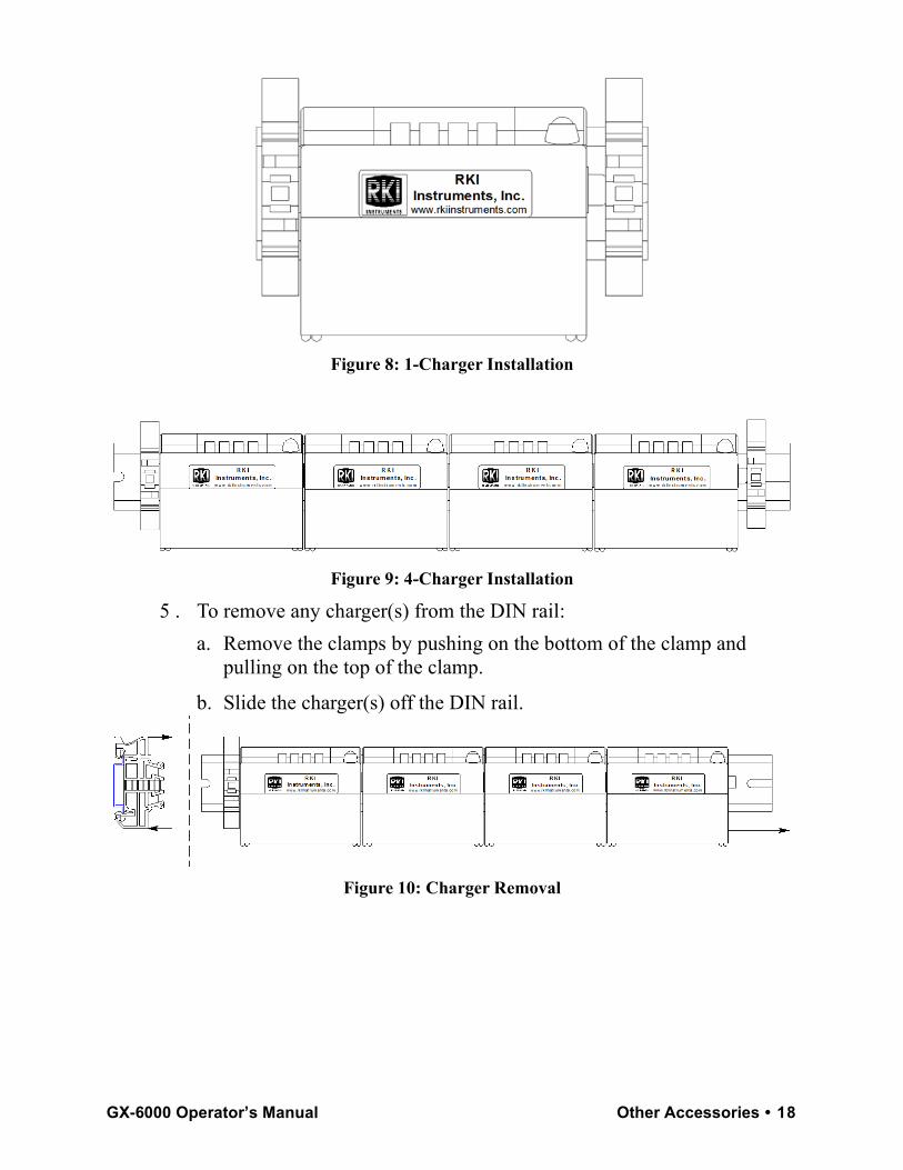
Figure 8: 1-Charger Installation
Figure 9: 4-Charger Installation
5 . To remove any charger(s) from the DIN rail: a. Remove the clamps by pushing on the bottom of the clamp and
pulling on the top of the clamp.
b. Slide the charger(s) off the DIN rail.
Figure 10: Charger Removal
GX-6000 Operator’s Manual Other Accessories • 18
Chapter 3: Operation
OverviewThis chapter explains how to use the GX-6000 to perform confined space entry monitoring or general area monitoring in Normal Mode. There are three operational modes in Normal Mode: Measuring Mode, Display Mode, and Calibration Mode. While in Normal Mode, the unit is normally operating in Measuring Mode. Display Mode and Calibration Mode are accessible from Measuring Mode. Display Mode is described in this chapter. Calibration Mode is described in “Chapter 4: Calibration Mode” on page 68.The GX-6000 can also operate in Leak Check Mode and Bar Hole Mode. See “Appendix E: Using the GX-6000 in Leak Check Mode” for operating instructions for Leak Check Mode. See “Appendix F: Using the GX-6000 in Bar Hole Mode” on page 215 for operating instructions for Bar Hole Mode.
Start UpThis section explains how to start up the GX-6000, get it ready for operation, and turn it off.
NOTE: The screens illustrated in this section are for a standard 4-gas + PID unit. The screens displayed by your GX-6000 may be slightly different.
Turning On the GX-6000To illustrate certain functions, the following description of the GX-6000 start up sequence assumes that the following menu items in Maintenance Mode are turned on: LUNCH BREAK, CAL REMINDER, BUMP REMINDER, and ID DISPLAY. If any of these items are turned off, then the corresponding screens will not appear.The GX-6000 may be used with a sample hose and probe or with the tapered rubber nozzle. Determine which configuration works best for your application.
NOTE: When the sample hose is not being used, its outgassing characteristics may result in a small buildup of gas to which the PID sensor will respond. If a sample hose has been sitting unused for a period of time, when that sample hose is connected to a GX-6000, the PID channel may temporarily show a reading. The reading will return to a fresh air reading after all of the built up gas has been drawn out of the sample hose.
19 • Overview GX-6000 Operator’s Manual
1 . Connect the tapered rubber nozzle or the sample hose and probe to the GX-6000’s quick connect inlet fitting.
2 . Press and briefly hold down the POWER/ENTER button. Release the button when you hear a beep.
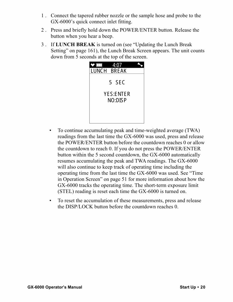
3 . If LUNCH BREAK is turned on (see “Updating the Lunch Break Setting” on page 161), the Lunch Break Screen appears. The unit counts down from 5 seconds at the top of the screen.
• To continue accumulating peak and time-weighted average (TWA) readings from the last time the GX-6000 was used, press and release the POWER/ENTER button before the countdown reaches 0 or allow the countdown to reach 0. If you do not press the POWER/ENTER button within the 5 second countdown, the GX-6000 automatically resumes accumulating the peak and TWA readings. The GX-6000 will also continue to keep track of operating time including the operating time from the last time the GX-6000 was used. See “Time in Operation Screen” on page 51 for more information about how the GX-6000 tracks the operating time. The short-term exposure limit (STEL) reading is reset each time the GX-6000 is turned on.
• To reset the accumulation of these measurements, press and release the DISP/LOCK button before the countdown reaches 0.
4:07LUNCH BREAK
5 SEC
YES:ENTERNO:DISP
GX-6000 Operator’s Manual Start Up • 20
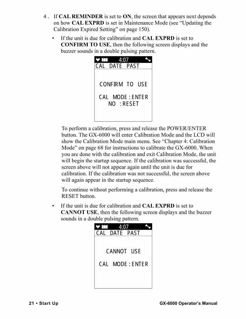
4 . If CAL REMINDER is set to ON, the screen that appears next depends on how CAL EXPRD is set in Maintenance Mode (see “Updating the Calibration Expired Setting” on page 150).
• If the unit is due for calibration and CAL EXPRD is set to CONFIRM TO USE, then the following screen displays and the buzzer sounds in a double pulsing pattern.
To perform a calibration, press and release the POWER/ENTER button. The GX-6000 will enter Calibration Mode and the LCD will show the Calibration Mode main menu. See “Chapter 4: Calibration Mode” on page 68 for instructions to calibrate the GX-6000. When you are done with the calibration and exit Calibration Mode, the unit will begin the startup sequence. If the calibration was successful, the screen above will not appear again until the unit is due for calibration. If the calibration was not successful, the screen above will again appear in the startup sequence.
To continue without performing a calibration, press and release the RESET button.
• If the unit is due for calibration and CAL EXPRD is set to CANNOT USE, then the following screen displays and the buzzer sounds in a double pulsing pattern.
4:07CAL DATE PAST
CONFIRM TO USE
CAL MODE : ENTERNO : RESET
4:07CAL DATE PAST
CANNOT USE
CAL MODE : ENTER
21 • Start Up GX-6000 Operator’s Manual
The GX-6000 cannot be used until a successful calibration has been performed. Press and release the POWER/ENTER button to enter Calibration Mode. See “Chapter 4: Calibration Mode” on page 68 for instructions to calibrate the GX-6000.
NOTE: In this situation, even if the User password function has been turned on, no password is required to perform a calibration.
When you are done with the calibration and exit Calibration Mode, the unit will begin the startup sequence. If the calibration was successful, the screen above will not appear again until the unit is due for calibration. If the calibration was not successful, the screen above will again appear in the startup sequence.
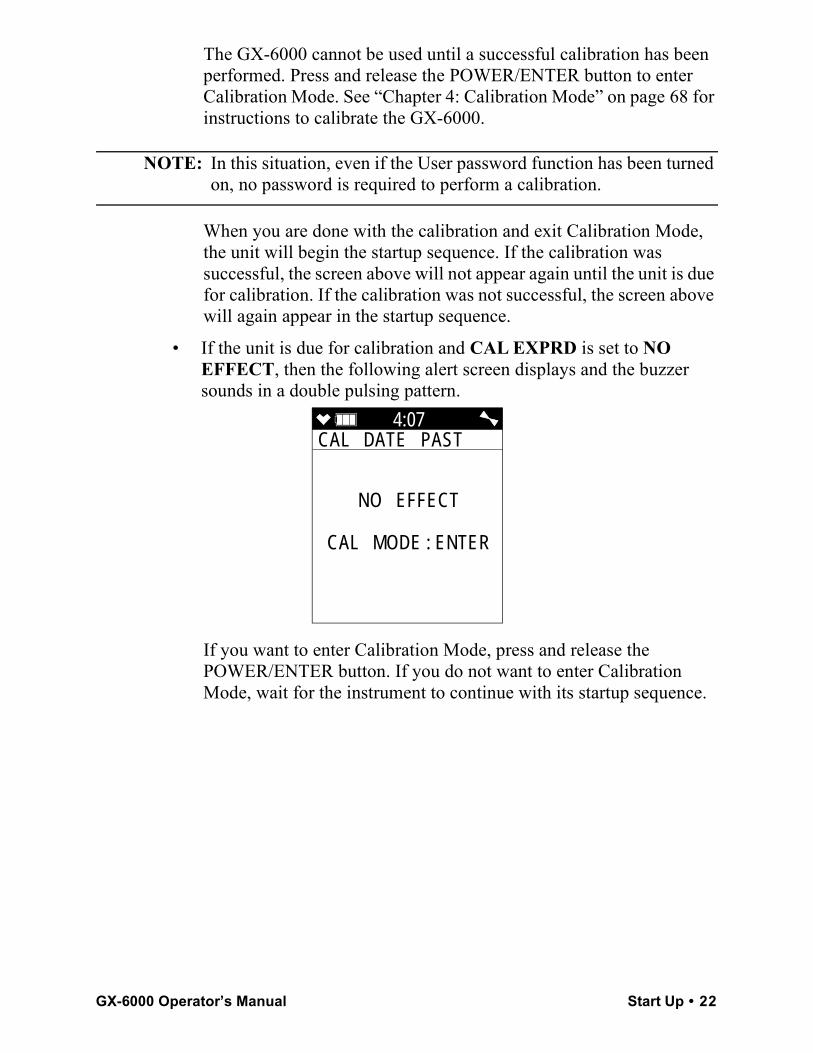
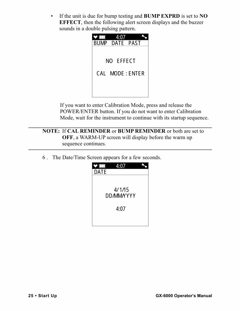
• If the unit is due for calibration and CAL EXPRD is set to NO EFFECT, then the following alert screen displays and the buzzer sounds in a double pulsing pattern.
If you want to enter Calibration Mode, press and release the POWER/ENTER button. If you do not want to enter Calibration Mode, wait for the instrument to continue with its startup sequence.
4:07CAL DATE PAST
NO EFFECT
CAL MODE : ENTER
GX-6000 Operator’s Manual Start Up • 22
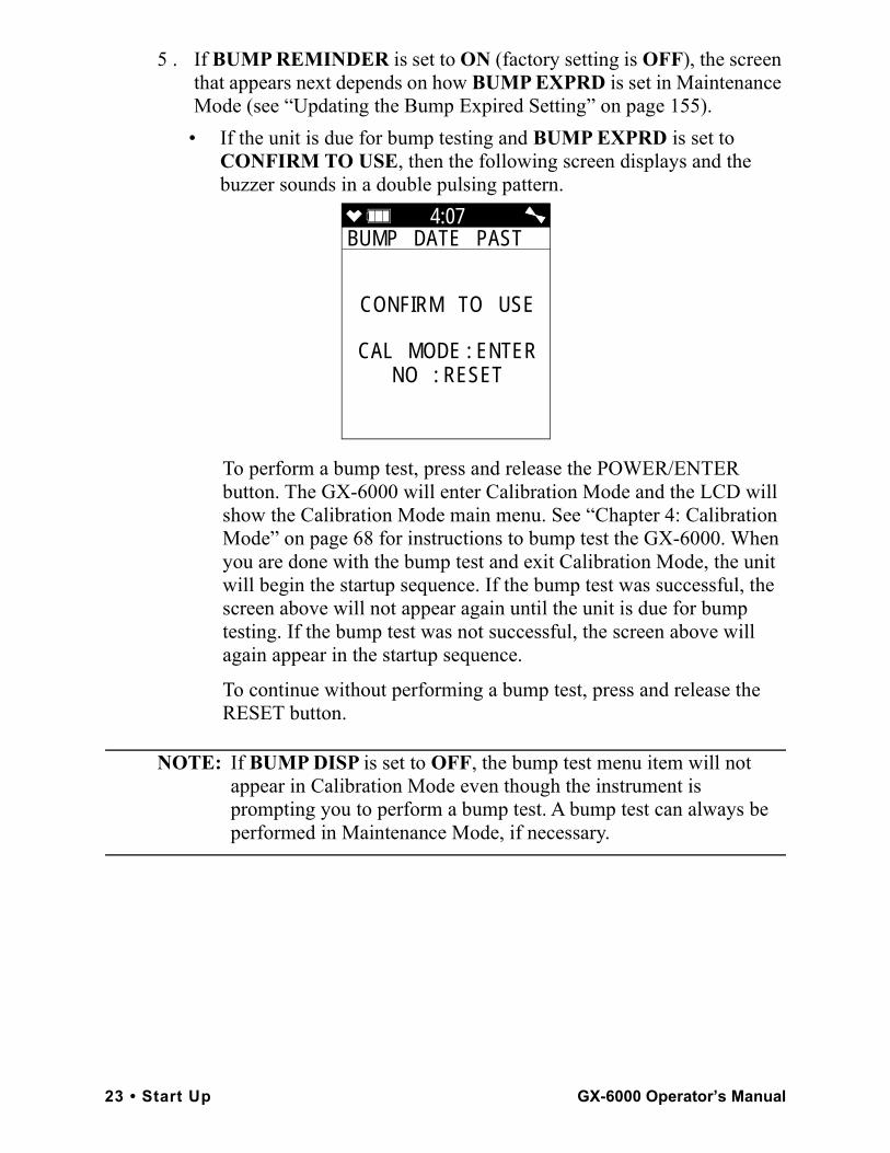
5 . If BUMP REMINDER is set to ON (factory setting is OFF), the screen that appears next depends on how BUMP EXPRD is set in Maintenance Mode (see “Updating the Bump Expired Setting” on page 155).
• If the unit is due for bump testing and BUMP EXPRD is set to CONFIRM TO USE, then the following screen displays and the buzzer sounds in a double pulsing pattern.
To perform a bump test, press and release the POWER/ENTER button. The GX-6000 will enter Calibration Mode and the LCD will show the Calibration Mode main menu. See “Chapter 4: Calibration Mode” on page 68 for instructions to bump test the GX-6000. When you are done with the bump test and exit Calibration Mode, the unit will begin the startup sequence. If the bump test was successful, the screen above will not appear again until the unit is due for bump testing. If the bump test was not successful, the screen above will again appear in the startup sequence.
To continue without performing a bump test, press and release the RESET button.
NOTE: If BUMP DISP is set to OFF, the bump test menu item will not appear in Calibration Mode even though the instrument is prompting you to perform a bump test. A bump test can always be performed in Maintenance Mode, if necessary.
4:07BUMP DATE PAST
CONFIRM TO USE
CAL MODE : ENTERNO : RESET
23 • Start Up GX-6000 Operator’s Manual
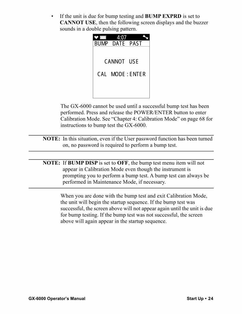
• If the unit is due for bump testing and BUMP EXPRD is set to CANNOT USE, then the following screen displays and the buzzer sounds in a double pulsing pattern.
The GX-6000 cannot be used until a successful bump test has been performed. Press and release the POWER/ENTER button to enter Calibration Mode. See “Chapter 4: Calibration Mode” on page 68 for instructions to bump test the GX-6000.
NOTE: In this situation, even if the User password function has been turned on, no password is required to perform a bump test.
NOTE: If BUMP DISP is set to OFF, the bump test menu item will not appear in Calibration Mode even though the instrument is prompting you to perform a bump test. A bump test can always be performed in Maintenance Mode, if necessary.
When you are done with the bump test and exit Calibration Mode, the unit will begin the startup sequence. If the bump test was successful, the screen above will not appear again until the unit is due for bump testing. If the bump test was not successful, the screen above will again appear in the startup sequence.
4:07BUMP DATE PAST
CANNOT USE
CAL MODE : ENTER
GX-6000 Operator’s Manual Start Up • 24
• If the unit is due for bump testing and BUMP EXPRD is set to NO EFFECT, then the following alert screen displays and the buzzer sounds in a double pulsing pattern.
If you want to enter Calibration Mode, press and release the POWER/ENTER button. If you do not want to enter Calibration Mode, wait for the instrument to continue with its startup sequence.
NOTE: If CAL REMINDER or BUMP REMINDER or both are set to OFF, a WARM-UP screen will display before the warm up sequence continues.
6 . The Date/Time Screen appears for a few seconds.
4:07BUMP DATE PAST
NO EFFECT
CAL MODE : ENTER
4:07DATE
4/ 1/15DD/MM/YYYY
4:07
25 • Start Up GX-6000 Operator’s Manual
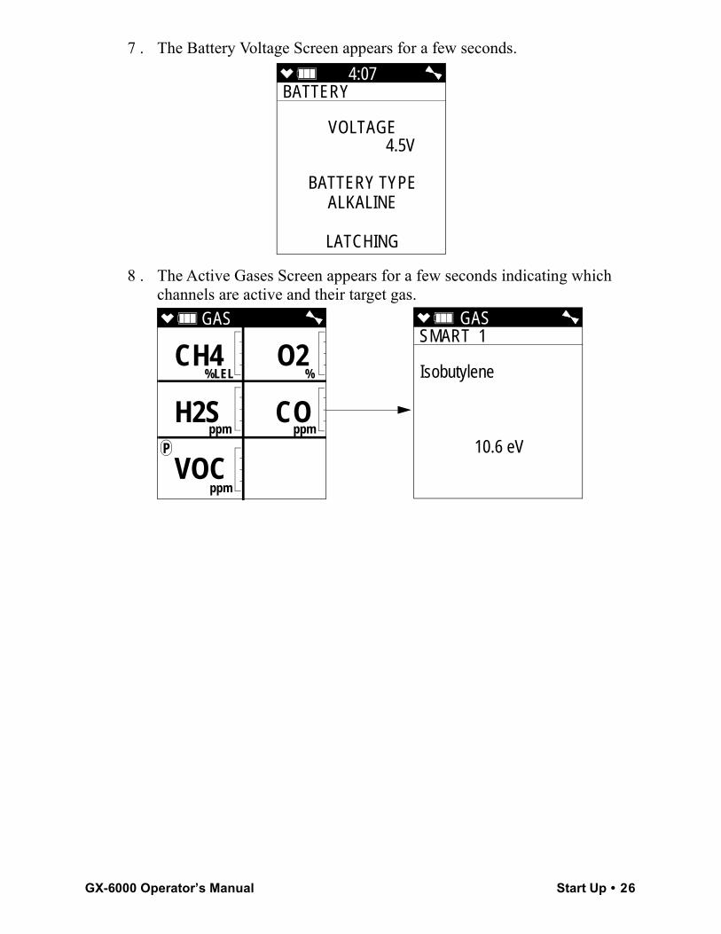
7 . The Battery Voltage Screen appears for a few seconds.
8 . The Active Gases Screen appears for a few seconds indicating which channels are active and their target gas.
4:07BATTERY
VOLTAGE 4.5V
BATTERY TYPEALKALINE
LATCHING
GAS
%LEL %
ppm ppm
P
ppm
CH4 O2
H2S CO
VOC
GAS SMART 1
Isobutylene
10.6 eV
GX-6000 Operator’s Manual Start Up • 26
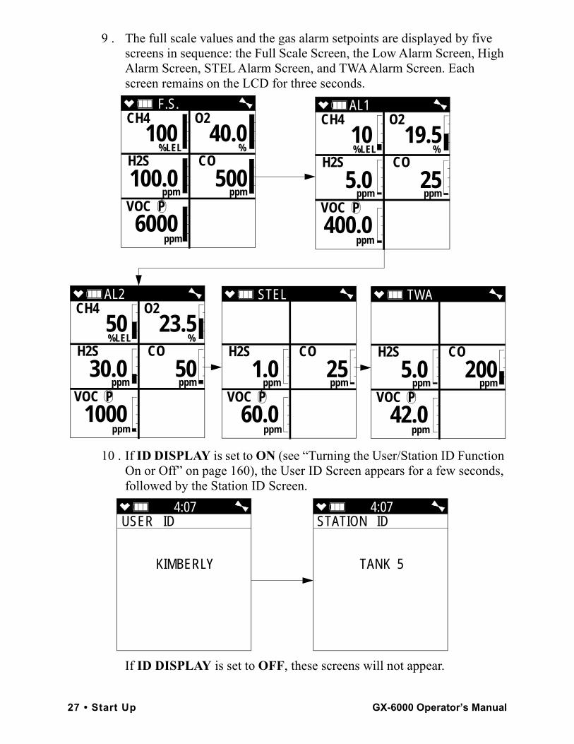
9 . The full scale values and the gas alarm setpoints are displayed by five screens in sequence: the Full Scale Screen, the Low Alarm Screen, High Alarm Screen, STEL Alarm Screen, and TWA Alarm Screen. Each screen remains on the LCD for three seconds.
10 . If ID DISPLAY is set to ON (see “Turning the User/Station ID Function On or Off” on page 160), the User ID Screen appears for a few seconds, followed by the Station ID Screen.
If ID DISPLAY is set to OFF, these screens will not appear.
F.S. CH4 O2
%LEL % H2S CO
ppm ppm
VOC P
ppm
100 40.0
100.0 500
6000
AL1 CH4 O2
%LEL % H2S CO
ppm ppm
VOC P
ppm
10 19.5
5.0 25
400.0
AL2 CH4 O2
%LEL % H2S CO
ppm ppm
VOC P
ppm
50 23.5
30.0 50
1000
STEL
H2S CO
ppm ppm
VOC P
ppm
1.0 25
60.0
TWA
H2S CO
ppm ppm
VOC P
ppm
5.0 200
42.0
4:07USER ID
KIMBERLY
4:07STATION ID
TANK 5
27 • Start Up GX-6000 Operator’s Manual
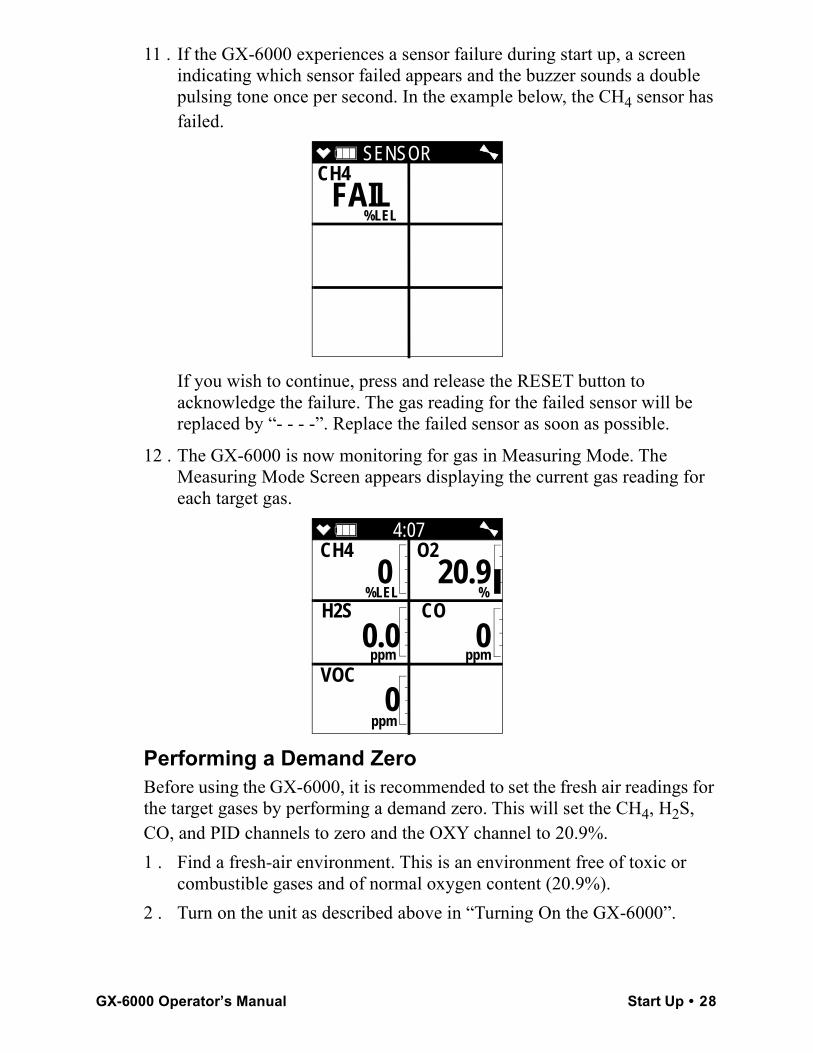
11 . If the GX-6000 experiences a sensor failure during start up, a screen indicating which sensor failed appears and the buzzer sounds a double pulsing tone once per second. In the example below, the CH4 sensor has failed.
If you wish to continue, press and release the RESET button to acknowledge the failure. The gas reading for the failed sensor will be replaced by “- - - -”. Replace the failed sensor as soon as possible.
12 . The GX-6000 is now monitoring for gas in Measuring Mode. The Measuring Mode Screen appears displaying the current gas reading for each target gas.
Performing a Demand ZeroBefore using the GX-6000, it is recommended to set the fresh air readings for the target gases by performing a demand zero. This will set the CH4, H2S, CO, and PID channels to zero and the OXY channel to 20.9%. 1 . Find a fresh-air environment. This is an environment free of toxic or
combustible gases and of normal oxygen content (20.9%).2 . Turn on the unit as described above in “Turning On the GX-6000”.
SENSOR CH4
%LEL
FAIL
4:07CH4 O2
%LEL % H2S CO
ppm ppm
VOC
ppm
0 20.9
0.0 0
0
GX-6000 Operator’s Manual Start Up • 28
3 . If you suspect any low-level VOC background in the area, you will need to use the VOC zero filter.
NOTE: If you have both a VOC and a CO2 sensor installed, you will need to follow the directions in “Performing a Demand Zero for Instruments with a Carbon Dioxide Sensor and a PID Sensor” on page 198 instead of following the directions shown below.
a. Remove the plug from each end of the VOC zero filter.
b. Attach the VOC zero filter to the inlet fitting or probe. The filter does not have a preferred flow direction.
c. Let the instrument draw through the VOC zero filter for 1 minute before continuing.
4 . Press and hold the ▲AIR button. The LCD prompts you to continue holding the ▲AIR button and the buzzer will pulse while you hold the button.
5 . Continue to hold the ▲AIR button until the LCD prompts you to release it. The GX-6000 will set the fresh air reading for all channels. Start up is complete and the unit is now ready for monitoring.
6 . If the VOC zero filter was used, remove the filter from the GX-6000’s inlet fitting or probe. Reinstall the plugs on each end of the filter.
Turning Off the GX-60001 . Press and hold the POWER/ENTER button.2 . TURN OFF will appear on the display and the buzzer will pulse for
about five seconds.3 . Release the button when TURN OFF disappears from the display.
Measuring Mode, Normal Operation
When the GX-6000 completes its startup sequence, it is in Measuring Mode. In Measuring Mode the GX-6000 continuously monitors the sampled atmosphere and displays the gas concentrations present for its target gases. In a low-light environment, press and release any button to turn on the display backlight. See “Updating the Backlight Time Setting” on page 160 to program backlight duration. If CONFIRMATION is set to ON in the Maintenance Mode menu (see “Updating the Confirmation Alert Setting” on page 163), the GX-6000 beeps periodically to confirm that it’s operating.
29 • Measuring Mode, Normal Operation GX-6000 Operator’s Manual
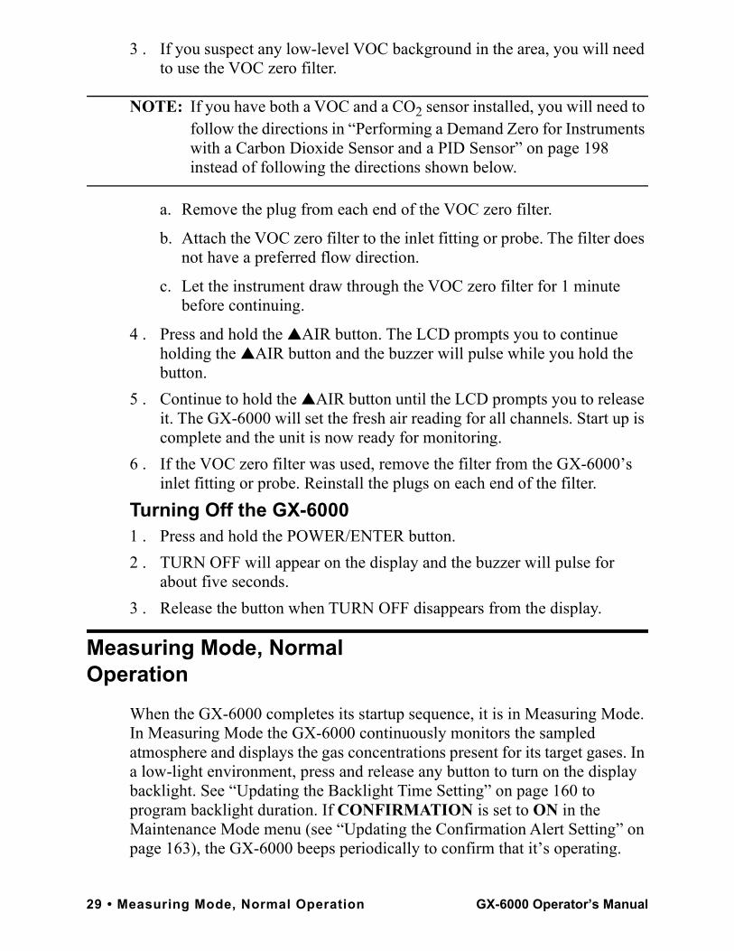
Monitoring an Area1 . Start up the GX-6000 as described above in “Start Up” on page 19. It is
now in Measuring Mode.
2 . Take the GX-6000 to the monitoring area.Put the probe tip in the area to be monitored.
NOTE: If the particle filter or hydrophobic filter become dirty or clogged, replace them. If water enters the probe, dry out or replace the particle filter (if installed) and shake any water out of the probe and off of the hydrophobic filter. If you notice that water has entered the flow system through the probe, replace the probe’s hydrophobic filter. See “Replacing the Probe’s Particle Filter and Hydrophobic Filter Disk” on page 115 for instructions to replace the particle filter and the hydrophobic filter.
3 . Wait 10 - 15 seconds and observe the display for gas readings. If a reading is observed, allow the reading to stabilize to determine the gas concentrations present.
NOTE: Response time increases with the length of the sample hose. Long sample hoses will require more time to show a response at the GX-6000. The maximum sample hose length recommended for the GX-6000 is 50 feet. Consult RKI Instruments, Inc. for longer sample hose lengths.
4 . If a gas alarm occurs, take appropriate action. See “Responding to Alarms” on page 38.
4:07CH4 O2
%LEL % H2S CO
ppm ppm
VOC
ppm
0 20.9
0.0 0
0
GX-6000 Operator’s Manual Measuring Mode, Normal Operation • 30
Using Optional Sample HosesThe standard sample hose for the GX-6000 is 3 feet long. Optional samples hoses and probes with longer hoses are available from 5 - 50 feet in 5 foot increments (see “General Parts List” on page 137). If you are considering using a hose and probe with a longer hose, keep in mind that a longer hose will increase the GX-6000’s response time and the flowrate may decrease close to the low flow alarm point.
CAUTION: Sample hose lengths of more than 50 feet are not recommended for the GX-6000 because of flow rate reduction and increased response time. Consult RKI Instruments, Inc. for hose lengths longer than 50 feet.
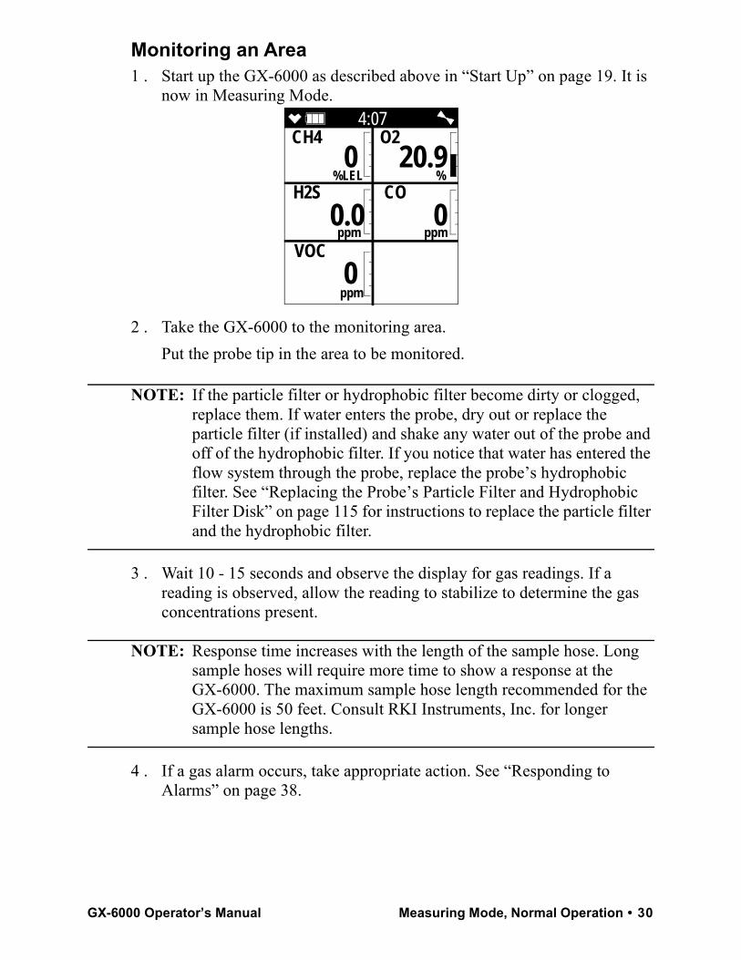
The chart below illustrates how response time is affected by the sample hose length.
Combustible Gas DetectionThere are three issues to keep in mind when monitoring for combustible gas. • The catalytic combustible sensor will respond to any combustible gas.
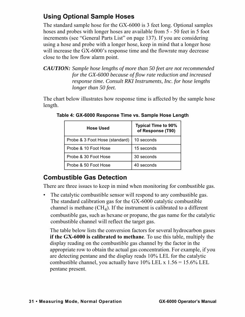
The standard calibration gas for the GX-6000 catalytic combustible channel is methane (CH4). If the instrument is calibrated to a different combustible gas, such as hexane or propane, the gas name for the catalytic combustible channel will reflect the target gas.The table below lists the conversion factors for several hydrocarbon gases if the GX-6000 is calibrated to methane. To use this table, multiply the display reading on the combustible gas channel by the factor in the appropriate row to obtain the actual gas concentration. For example, if you are detecting pentane and the display reads 10% LEL for the catalytic combustible channel, you actually have 10% LEL x 1.56 = 15.6% LEL pentane present.
Table 4: GX-6000 Response Time vs. Sample Hose Length
Hose Used Typical Time to 90% of Response (T90)
Probe & 3 Foot Hose (standard) 10 seconds
Probe & 10 Foot Hose 15 seconds
Probe & 30 Foot Hose 30 seconds
Probe & 50 Foot Hose 40 seconds
31 • Measuring Mode, Normal Operation GX-6000 Operator’s Manual
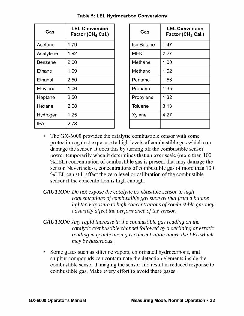
Table 5: LEL Hydrocarbon Conversions
• The GX-6000 provides the catalytic combustible sensor with some protection against exposure to high levels of combustible gas which can damage the sensor. It does this by turning off the combustible sensor power temporarily when it determines that an over scale (more than 100 %LEL) concentration of combustible gas is present that may damage the sensor. Nevertheless, concentrations of combustible gas of more than 100 %LEL can still affect the zero level or calibration of the combustible sensor if the concentration is high enough.
CAUTION: Do not expose the catalytic combustible sensor to high concentrations of combustible gas such as that from a butane lighter. Exposure to high concentrations of combustible gas may adversely affect the performance of the sensor.
CAUTION: Any rapid increase in the combustible gas reading on the catalytic combustible channel followed by a declining or erratic reading may indicate a gas concentration above the LEL which may be hazardous.
• Some gases such as silicone vapors, chlorinated hydrocarbons, and sulphur compounds can contaminate the detection elements inside the combustible sensor damaging the sensor and result in reduced response to combustible gas. Make every effort to avoid these gases.
Gas LEL Conversion Factor (CH4 Cal.) Gas LEL Conversion
Factor (CH4 Cal.)
Acetone 1.79 Iso Butane 1.47
Acetylene 1.92 MEK 2.27
Benzene 2.00 Methane 1.00
Ethane 1.09 Methanol 1.92
Ethanol 2.50 Pentane 1.56
Ethylene 1.06 Propane 1.35
Heptane 2.50 Propylene 1.32
Hexane 2.08 Toluene 3.13
Hydrogen 1.25 Xylene 4.27
IPA 2.78
GX-6000 Operator’s Manual Measuring Mode, Normal Operation • 32
VOC DetectionWhen monitoring for VOCs using the PID sensor, keep the following in mind:• Regardless of what gas the PID sensor is calibrated to (factory calibration
is to isobutylene), the PID sensor will still detect and respond to a variety of volatile organic compounds (VOCs).
• The PID channel will indicate an upscale reading if one of a variety of combustible gases is present. If %LEL concentrations of one of these combustible gases is present, the PID channel may indicate an overscale reading.
• If concentrations of methane greater than 10% LEL are present in the monitoring environment, the PID channel’s reading will be suppressed.
• The PID sensor will also respond to H2S and NH3, so if H2S or NH3 is present, the PID channel may indicate an upscale reading depending on the concentration present.
• If your instrument has both a low range PID sensor and a high range PID sensor installed and if you are monitoring for gases in the higher range, the low range PID channel may be in over range alarm while monitoring, depending on the level of VOCs present.
Oxygen DetectionExposing the galvanic oxygen sensor to halogen gas or sulfides may shorten the sensor’s life or cause malfunctions or inaccurate gas readings. Minimize the sensor’s exposure to these gases as much as possible. If exposure occurs, allow the instrument to draw fresh air and confirm that the readings return to fresh air values.
33 • Measuring Mode, Normal Operation GX-6000 Operator’s Manual
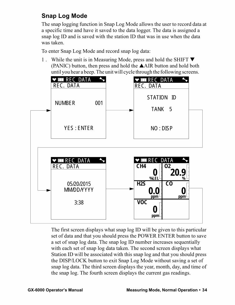
Snap Log ModeThe snap logging function in Snap Log Mode allows the user to record data at a specific time and have it saved to the data logger. The data is assigned a snap log ID and is saved with the station ID that was in use when the data was taken.To enter Snap Log Mode and record snap log data:1 . While the unit is in Measuring Mode, press and hold the SHIFT ▼
(PANIC) button, then press and hold the ▲AIR button and hold both until you hear a beep. The unit will cycle through the following screens.
The first screen displays what snap log ID will be given to this particular set of data and that you should press the POWER ENTER button to save a set of snap log data. The snap log ID number increases sequentially with each set of snap log data taken. The second screen displays what Station ID will be associated with this snap log and that you should press the DISP/LOCK button to exit Snap Log Mode without saving a set of snap log data. The third screen displays the year, month, day, and time of the snap log. The fourth screen displays the current gas readings.
REC DATA REC. DATA
NUMBER 001
YES : ENTER
REC DATA REC. DATA
STATION ID
TANK 5
NO : DISP
REC DATA REC. DATA
05/20/2015MM/DD/YYYY
3:38
REC DATA CH4 O2
%LEL % H2S CO
ppm ppm
VOC
ppm
0 20.9
0.0 0
0
GX-6000 Operator’s Manual Measuring Mode, Normal Operation • 34
NOTE: If the GX-6000 detects an alarm condition while in Snap Log Mode, it will automatically exit Snap Log Mode and return to Measuring Mode. You may then reenter Snap Log Mode and take snap logs while the instrument is still in alarm.
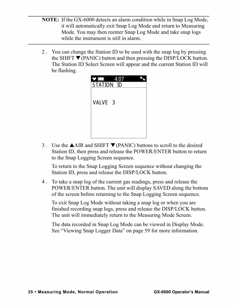
2 . You can change the Station ID to be used with the snap log by pressing the SHIFT ▼ (PANIC) button and then pressing the DISP/LOCK button. The Station ID Select Screen will appear and the current Station ID will be flashing.
3 . Use the ▲AIR and SHIFT ▼ (PANIC) buttons to scroll to the desired Station ID, then press and release the POWER/ENTER button to return to the Snap Logging Screen sequence.To return to the Snap Logging Screen sequence without changing the Station ID, press and release the DISP/LOCK button.
4 . To take a snap log of the current gas readings, press and release the POWER/ENTER button. The unit will display SAVED along the bottom of the screen before returning to the Snap Logging Screen sequence.To exit Snap Log Mode without taking a snap log or when you are finished recording snap logs, press and release the DISP/LOCK button. The unit will immediately return to the Measuring Mode Screen.
The data recorded in Snap Log Mode can be viewed in Display Mode. See “Viewing Snap Logger Data” on page 59 for more information.
4:07STATION ID
VALVE 3
35 • Measuring Mode, Normal Operation GX-6000 Operator’s Manual
Measuring Mode, AlarmsThis section covers alarm indications in Measuring Mode. It also describes how to reset the GX-6000 after an alarm has occurred and how to respond to an alarm condition.
NOTE: False alarms may be caused by radio frequency (RF) or electromagnetic (EMI) interference. Keep the GX-6000 away from RF and EMI sources such as radio transmitters or large motors.
Alarm IndicationsThe GX-6000 buzzer will sound an alarm, the LEDs will flash, and the vibrator will pulse when any sort of alarm condition or failure is encountered.
NOTE: If an alarm condition occurs while you are in Display Mode, the GX-6000 will automatically bring up the alarm screen instead.
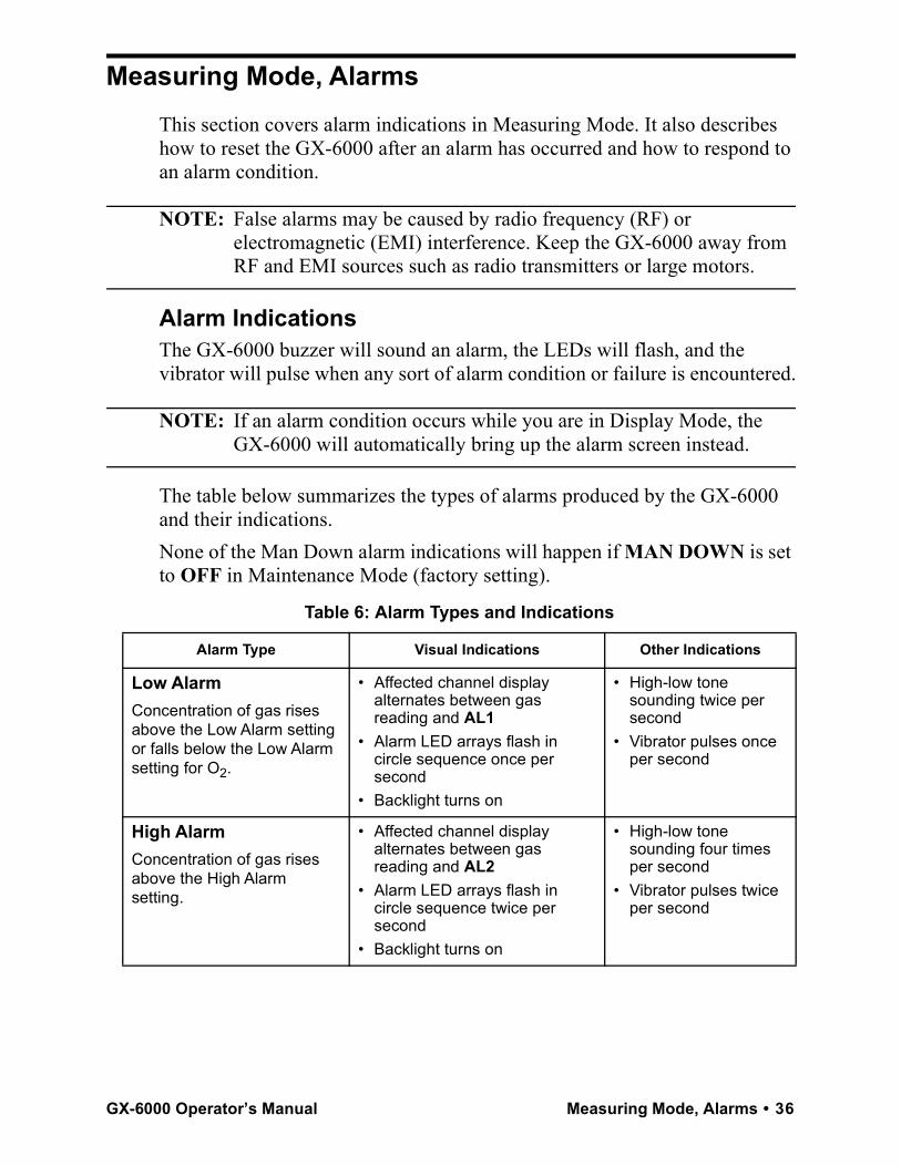
The table below summarizes the types of alarms produced by the GX-6000 and their indications.None of the Man Down alarm indications will happen if MAN DOWN is set to OFF in Maintenance Mode (factory setting).
Table 6: Alarm Types and Indications
Alarm Type Visual Indications Other Indications
Low AlarmConcentration of gas rises above the Low Alarm setting or falls below the Low Alarm setting for O2.
• Affected channel display alternates between gas reading and AL1
• Alarm LED arrays flash in circle sequence once per second
• Backlight turns on
• High-low tone sounding twice per second
• Vibrator pulses once per second
High AlarmConcentration of gas rises above the High Alarm setting.
• Affected channel display alternates between gas reading and AL2
• Alarm LED arrays flash in circle sequence twice per second
• Backlight turns on
• High-low tone sounding four times per second
• Vibrator pulses twice per second
GX-6000 Operator’s Manual Measuring Mode, Alarms • 36
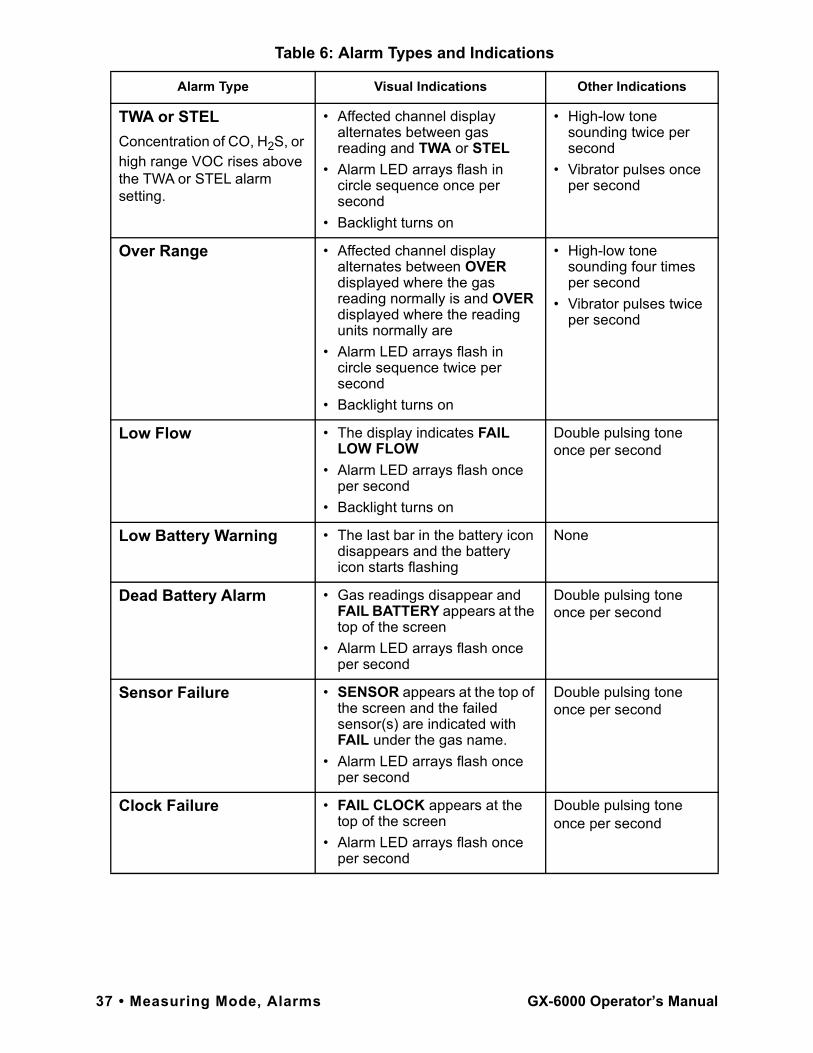
TWA or STELConcentration of CO, H2S, or high range VOC rises above the TWA or STEL alarm setting.
• Affected channel display alternates between gas reading and TWA or STEL
• Alarm LED arrays flash in circle sequence once per second
• Backlight turns on
• High-low tone sounding twice per second
• Vibrator pulses once per second
Over Range • Affected channel display alternates between OVER displayed where the gas reading normally is and OVER displayed where the reading units normally are
• Alarm LED arrays flash in circle sequence twice per second
• Backlight turns on
• High-low tone sounding four times per second
• Vibrator pulses twice per second
Low Flow • The display indicates FAIL LOW FLOW
• Alarm LED arrays flash once per second
• Backlight turns on
Double pulsing tone once per second
Low Battery Warning • The last bar in the battery icon disappears and the battery icon starts flashing
None
Dead Battery Alarm • Gas readings disappear and FAIL BATTERY appears at the top of the screen
• Alarm LED arrays flash once per second
Double pulsing tone once per second
Sensor Failure • SENSOR appears at the top of the screen and the failed sensor(s) are indicated with FAIL under the gas name.
• Alarm LED arrays flash once per second
Double pulsing tone once per second
Clock Failure • FAIL CLOCK appears at the top of the screen
• Alarm LED arrays flash once per second
Double pulsing tone once per second
Table 6: Alarm Types and Indications
Alarm Type Visual Indications Other Indications
37 • Measuring Mode, Alarms GX-6000 Operator’s Manual
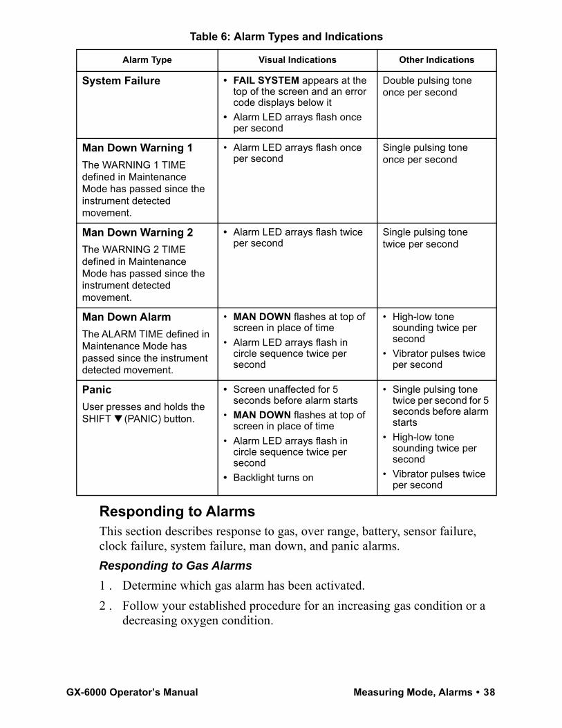
Responding to AlarmsThis section describes response to gas, over range, battery, sensor failure, clock failure, system failure, man down, and panic alarms.Responding to Gas Alarms1 . Determine which gas alarm has been activated.2 . Follow your established procedure for an increasing gas condition or a
decreasing oxygen condition.
System Failure • FAIL SYSTEM appears at the top of the screen and an error code displays below it
• Alarm LED arrays flash once per second
Double pulsing tone once per second
Man Down Warning 1The WARNING 1 TIME defined in Maintenance Mode has passed since the instrument detected movement.
• Alarm LED arrays flash once per second
Single pulsing tone once per second
Man Down Warning 2The WARNING 2 TIME defined in Maintenance Mode has passed since the instrument detected movement.
• Alarm LED arrays flash twice per second
Single pulsing tone twice per second
Man Down AlarmThe ALARM TIME defined in Maintenance Mode has passed since the instrument detected movement.
• MAN DOWN flashes at top of screen in place of time
• Alarm LED arrays flash in circle sequence twice per second
• High-low tone sounding twice per second
• Vibrator pulses twice per second
PanicUser presses and holds the SHIFT ▼ (PANIC) button.
• Screen unaffected for 5 seconds before alarm starts
• MAN DOWN flashes at top of screen in place of time
• Alarm LED arrays flash in circle sequence twice per second
• Backlight turns on
• Single pulsing tone twice per second for 5 seconds before alarm starts
• High-low tone sounding twice per second
• Vibrator pulses twice per second
Table 6: Alarm Types and Indications
Alarm Type Visual Indications Other Indications
GX-6000 Operator’s Manual Measuring Mode, Alarms • 38
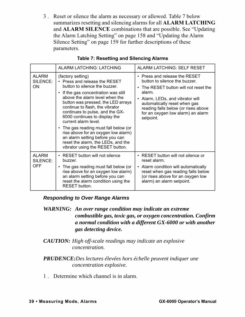
3 . Reset or silence the alarm as necessary or allowed. Table 7 below summarizes resetting and silencing alarms for all ALARM LATCHING and ALARM SILENCE combinations that are possible. See “Updating the Alarm Latching Setting” on page 158 and “Updating the Alarm Silence Setting” on page 159 for further descriptions of these parameters.
Responding to Over Range Alarms
WARNING: An over range condition may indicate an extreme combustible gas, toxic gas, or oxygen concentration. Confirm a normal condition with a different GX-6000 or with another gas detecting device.
CAUTION: High off-scale readings may indicate an explosive concentration.
PRUDENCE:Des lectures élevées hors échelle peuvent indiquer une concentration explosive.
1 . Determine which channel is in alarm.
Table 7: Resetting and Silencing Alarms
ALARM LATCHING: LATCHING ALARM LATCHING: SELF RESET
ALARM SILENCE: ON
(factory setting) • Press and release the RESET
button to silence the buzzer. • If the gas concentration was still
above the alarm level when the button was pressed, the LED arrays continue to flash, the vibrator continues to pulse, and the GX-6000 continues to display the current alarm level.
• The gas reading must fall below (or rise above for an oxygen low alarm) an alarm setting before you can reset the alarm, the LEDs, and the vibrator using the RESET button.
• Press and release the RESET button to silence the buzzer.
• The RESET button will not reset the alarm.
• Alarm, LEDs, and vibrator will automatically reset when gas reading falls below (or rises above for an oxygen low alarm) an alarm setpoint.
ALARM SILENCE: OFF
• RESET button will not silence buzzer.
• The gas reading must fall below (or rise above for an oxygen low alarm) an alarm setting before you can reset the alarm condition using the RESET button.
• RESET button will not silence or reset alarm.
• Alarm condition will automatically reset when gas reading falls below (or rises above for an oxygen low alarm) an alarm setpoint.
39 • Measuring Mode, Alarms GX-6000 Operator’s Manual
2 . Follow your established procedure for an extreme gas condition.
NOTE: If your instrument has both a low range PID sensor and a high range PID sensor installed and if you are monitoring for gases in the higher range, the low range PID channel may be in over range alarm while monitoring, depending on the level of VOCs present.
3 . Reset the alarm using the RESET button once the alarm condition has cleared.
4 . Calibrate the GX-6000 as described in “Chapter 4: Calibration Mode” on page 68.
5 . If the over range condition continues or if you are not able to successfully calibrate the unit, you may need to replace the sensor that has triggered the over range alarm.
6 . If the over range condition continues after you have replaced the sensor, contact RKI Instruments, Inc. for further instructions.
Responding to Battery Alarms
WARNING: The GX-6000 is not operational as a gas monitoring device during a dead battery alarm. Take the Model GX-6000 to a non-hazardous area and replace or recharge the batteries as described in “Replacing or Recharging the Batteries” on page 106.
The GX-6000 is fully functional during a low battery warning. However, only a limited amount of operating time remains, approximately 1 - 2 hours. The amount of time depends on how often the LCD backlight is used and how often the unit is responding to alarm conditions. Recharge the Li-ion battery pack or replace the alkaline batteries as soon as possible as described in “Replacing or Recharging the Batteries” on page 106.
NOTE: Alarms and the LCD back light consume battery power and reduce the amount of operating time remaining.
Responding to Sensor Failure Alarms1 . Determine which sensor has triggered the sensor failure alarm. 2 . Try calibrating the failed sensor, as described in “Chapter 4: Calibration
Mode” on page 68 before replacing it.3 . If the sensor failure continues, replace the sensor as described in
“Replacing a Sensor” on page 120.
GX-6000 Operator’s Manual Measuring Mode, Alarms • 40
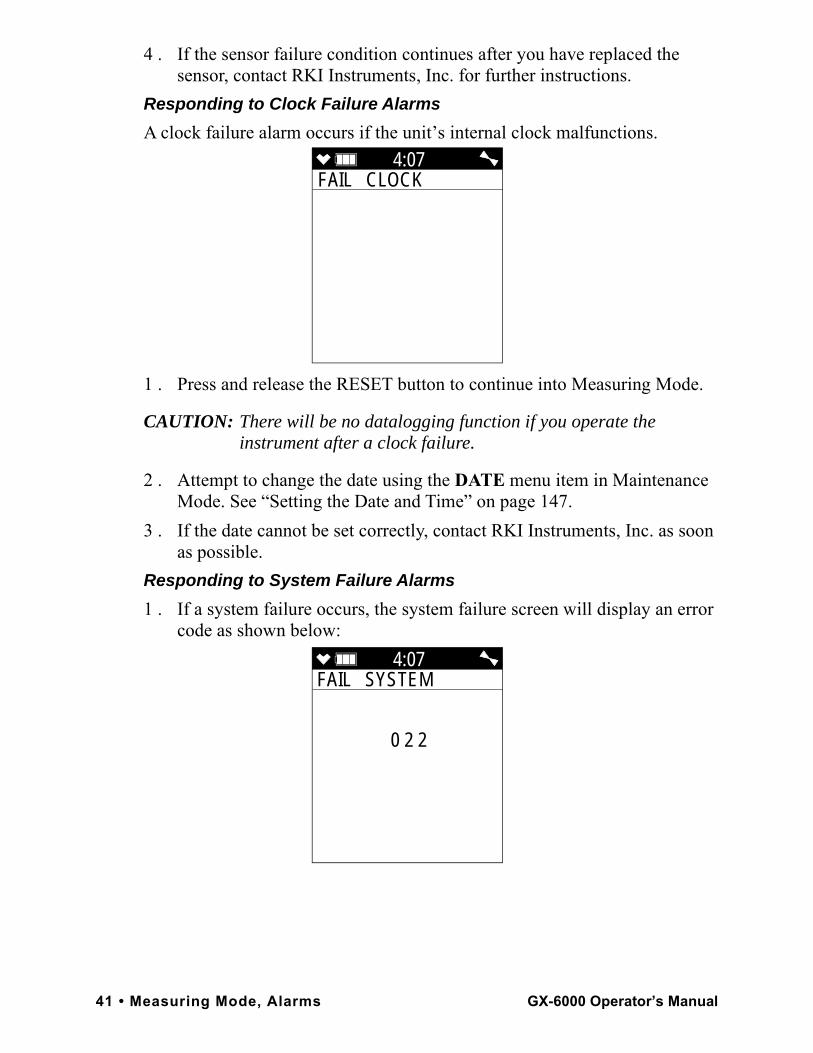
4 . If the sensor failure condition continues after you have replaced the sensor, contact RKI Instruments, Inc. for further instructions.
Responding to Clock Failure AlarmsA clock failure alarm occurs if the unit’s internal clock malfunctions.
1 . Press and release the RESET button to continue into Measuring Mode.
CAUTION: There will be no datalogging function if you operate the instrument after a clock failure.
2 . Attempt to change the date using the DATE menu item in Maintenance Mode. See “Setting the Date and Time” on page 147.
3 . If the date cannot be set correctly, contact RKI Instruments, Inc. as soon as possible.
Responding to System Failure Alarms1 . If a system failure occurs, the system failure screen will display an error
code as shown below:
4:07FAIL CLOCK
4:07FAIL SYSTEM
0 2 2
41 • Measuring Mode, Alarms GX-6000 Operator’s Manual
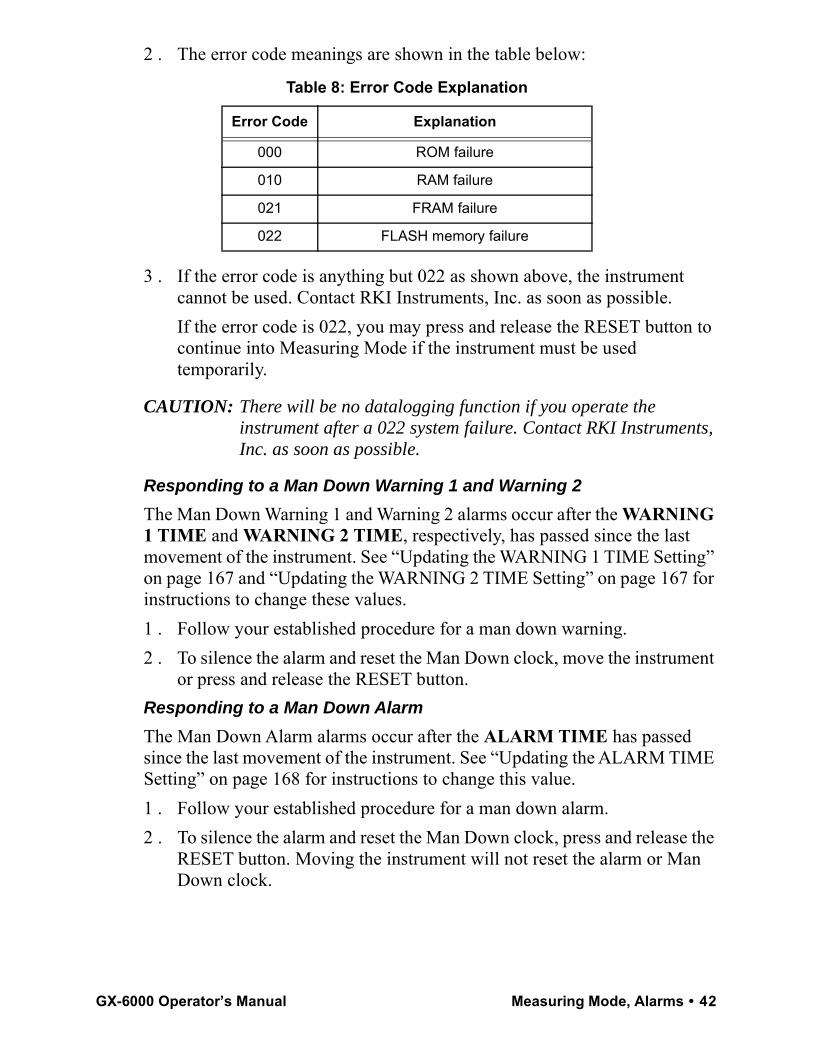
2 . The error code meanings are shown in the table below:
3 . If the error code is anything but 022 as shown above, the instrument cannot be used. Contact RKI Instruments, Inc. as soon as possible.If the error code is 022, you may press and release the RESET button to continue into Measuring Mode if the instrument must be used temporarily.
CAUTION: There will be no datalogging function if you operate the instrument after a 022 system failure. Contact RKI Instruments, Inc. as soon as possible.
Responding to a Man Down Warning 1 and Warning 2The Man Down Warning 1 and Warning 2 alarms occur after the WARNING 1 TIME and WARNING 2 TIME, respectively, has passed since the last movement of the instrument. See “Updating the WARNING 1 TIME Setting” on page 167 and “Updating the WARNING 2 TIME Setting” on page 167 for instructions to change these values.1 . Follow your established procedure for a man down warning.2 . To silence the alarm and reset the Man Down clock, move the instrument
or press and release the RESET button.Responding to a Man Down AlarmThe Man Down Alarm alarms occur after the ALARM TIME has passed since the last movement of the instrument. See “Updating the ALARM TIME Setting” on page 168 for instructions to change this value.1 . Follow your established procedure for a man down alarm.2 . To silence the alarm and reset the Man Down clock, press and release the
RESET button. Moving the instrument will not reset the alarm or Man Down clock.
Table 8: Error Code Explanation
Error Code Explanation
000 ROM failure
010 RAM failure
021 FRAM failure
022 FLASH memory failure
GX-6000 Operator’s Manual Measuring Mode, Alarms • 42
Responding to a Panic AlarmIf the user is in a dangerous situation or feels that others must be alerted to any sort of problem, holding the SHIFT ▼ (PANIC) button will initiate a panic alarm.1 . Press and release the RESET button to silence and reset the alarm.
Display ModeTwo other operating modes are accessible when the GX-6000 is in Measuring Mode. They are Display Mode and Calibration Mode. This section describes using the GX-6000 in Display Mode. See Table 9 below for a list of Display Mode’s menu items, a short description of each item, and the page number for further description.
Table 9: Display Mode Items
Menu Item (page number) Description
SELECT PID LIST (pg.45) Define the PID channel’s gas name
PEAK (pg.47) View and clear peak readings
STEL (pg.48) View STEL readings (H2S, CO, and high range PID only)
TWA (pg.48) View TWA readings (H2S, CO, and high range PID only)
ALARM POINTS (pg.49) View the alarm points
OPERATION TIME (pg.51) View the time in operation
DATE AND BATTERY (pg.51) View the date/time, battery voltage, and battery type
LOG REMAIN (pg.52) View the log time remaining
LOG CLEAR (pg.52) Clear the log data
PUMP OFF (pg.54) Turn the pump on or off (if the PUMP OFF DISP item in Maintenance Mode is set to ON)
USER ID (pg.55) Select the user ID (if the ID DISPLAY item in Maintenance Mode is set to ON)
STATION ID (pg.57) Select the station ID (if the ID DISPLAY item in Maintenance Mode is set to ON)
REC. DATA DISP (pg.59) View snap logger data
PEAK BAR (pg.60) Turn the peak bar function on or off
GAS DISP (pg.61) Change how the gas readings are displayed
INVERT SELECT (pg.62) Turn the LCD flip function on or off
CAT (LEL) SENSOR (pg.63) Turn the combustible sensor protection on or off
43 • Display Mode GX-6000 Operator’s Manual
Tips for Using Display Mode• To enter Display Mode and scroll from one menu item to the next or skip
an item when a question is asked, press and release the DISP/LOCK button.
• To enter an item, press and release the POWER/ENTER button.• To change a flashing parameter, use either the ▲AIR button or SHIFT ▼
(PANIC) button.• To return to Measuring Mode from the top level of any menu item, press
and release the RESET button.
NOTE: With the exception of the Pump Off Screen, each screen displays for 20 seconds. If you do not press a button within 20 seconds, the GX-6000 automatically returns to Measuring Mode. If the Pump Off Screen is used to turn the instrument’s pump off, the Pump Off Screen will display until you turn the pump back on.
LCD BACKGROUND (pg.64) Reverse the black/white of the LCD
LANGUAGE (pg.65) Change the instrument’s language back to English (only appears if the language has been changed to something other than English)
Table 9: Display Mode Items
Menu Item (page number) Description
GX-6000 Operator’s Manual Display Mode • 44
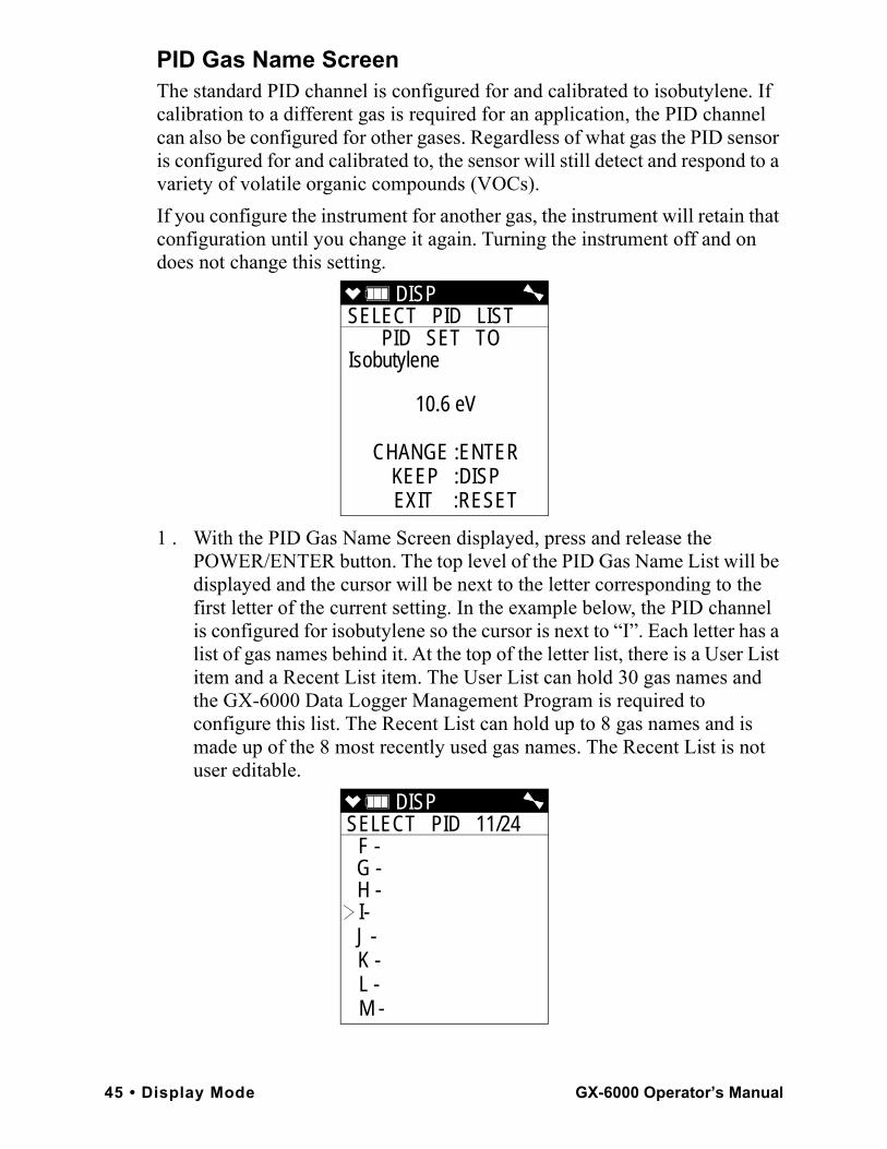
PID Gas Name ScreenThe standard PID channel is configured for and calibrated to isobutylene. If calibration to a different gas is required for an application, the PID channel can also be configured for other gases. Regardless of what gas the PID sensor is configured for and calibrated to, the sensor will still detect and respond to a variety of volatile organic compounds (VOCs).If you configure the instrument for another gas, the instrument will retain that configuration until you change it again. Turning the instrument off and on does not change this setting.
1 . With the PID Gas Name Screen displayed, press and release the POWER/ENTER button. The top level of the PID Gas Name List will be displayed and the cursor will be next to the letter corresponding to the first letter of the current setting. In the example below, the PID channel is configured for isobutylene so the cursor is next to “I”. Each letter has a list of gas names behind it. At the top of the letter list, there is a User List item and a Recent List item. The User List can hold 30 gas names and the GX-6000 Data Logger Management Program is required to configure this list. The Recent List can hold up to 8 gas names and is made up of the 8 most recently used gas names. The Recent List is not user editable.
DISP SELECT PID LIST
PID SET TO Isobutylene
10.6 eV
CHANGE :ENTERKEEP :DISP
EXIT :RESET
DISP SELECT PID 11/24
F - G - H - I- J - K - L - M -
45 • Display Mode GX-6000 Operator’s Manual
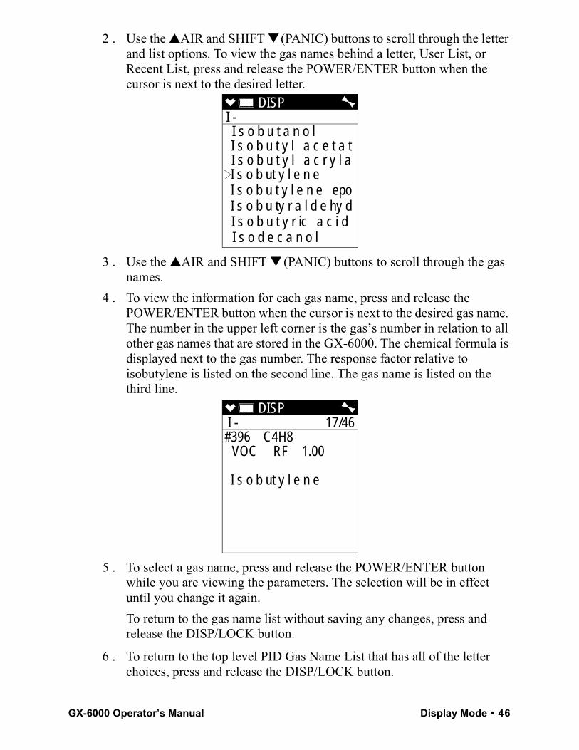
2 . Use the ▲AIR and SHIFT ▼ (PANIC) buttons to scroll through the letter and list options. To view the gas names behind a letter, User List, or Recent List, press and release the POWER/ENTER button when the cursor is next to the desired letter.
3 . Use the ▲AIR and SHIFT ▼ (PANIC) buttons to scroll through the gas names.
4 . To view the information for each gas name, press and release the POWER/ENTER button when the cursor is next to the desired gas name. The number in the upper left corner is the gas’s number in relation to all other gas names that are stored in the GX-6000. The chemical formula is displayed next to the gas number. The response factor relative to isobutylene is listed on the second line. The gas name is listed on the third line.
5 . To select a gas name, press and release the POWER/ENTER button while you are viewing the parameters. The selection will be in effect until you change it again.To return to the gas name list without saving any changes, press and release the DISP/LOCK button.
6 . To return to the top level PID Gas Name List that has all of the letter choices, press and release the DISP/LOCK button.
DISP I - I s o b u t a n o l I s o b u t y l a c e t a tI s o b u t y l a c r y l aI s o b ut y l e n e I s o b u t y l e n e epoI s o b u ty r a l d e hy dI s o b u t y r ic a c i d I s o d e c a n o l
DISP I - 17/46
#396 C4H8 VOC RF 1.00
I s o b ut y l e n e
GX-6000 Operator’s Manual Display Mode • 46
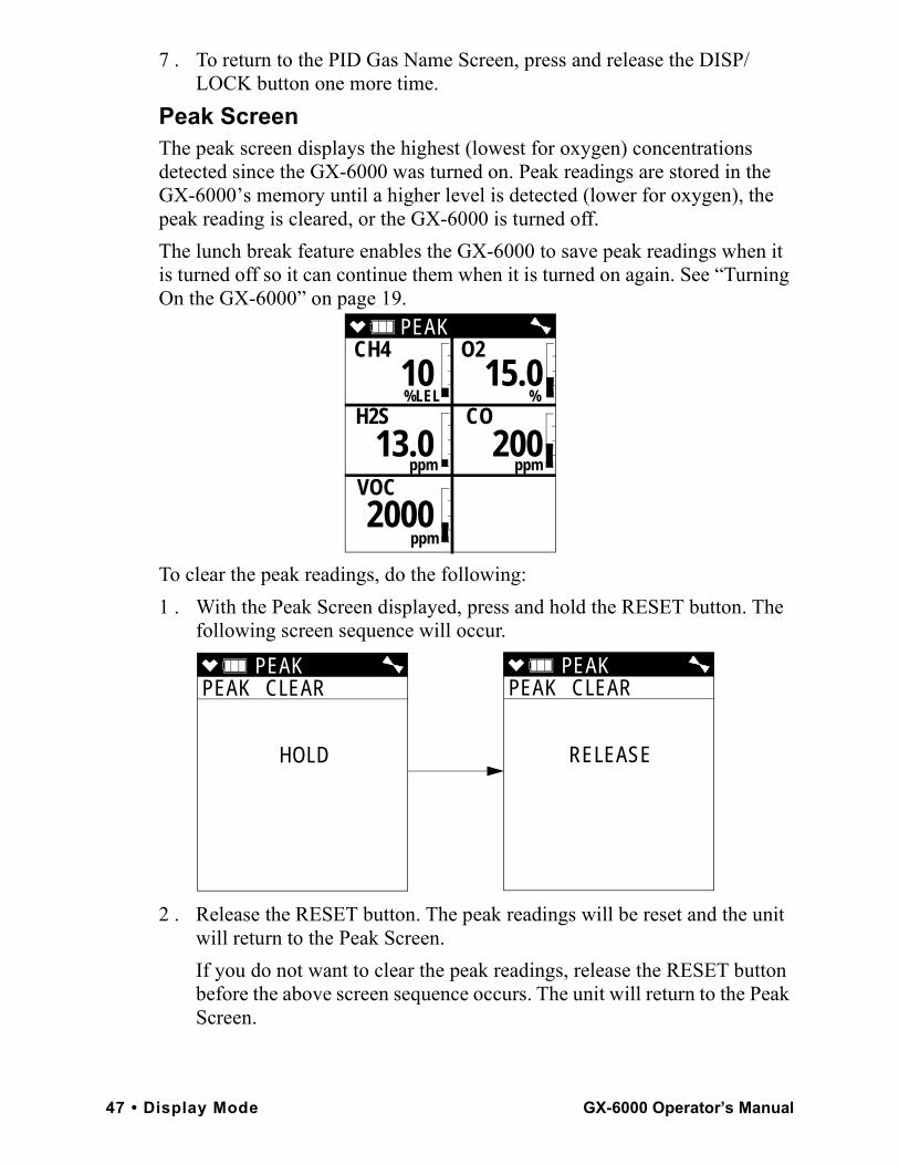
7 . To return to the PID Gas Name Screen, press and release the DISP/LOCK button one more time.
Peak ScreenThe peak screen displays the highest (lowest for oxygen) concentrations detected since the GX-6000 was turned on. Peak readings are stored in the GX-6000’s memory until a higher level is detected (lower for oxygen), the peak reading is cleared, or the GX-6000 is turned off.The lunch break feature enables the GX-6000 to save peak readings when it is turned off so it can continue them when it is turned on again. See “Turning On the GX-6000” on page 19.
To clear the peak readings, do the following:1 . With the Peak Screen displayed, press and hold the RESET button. The
following screen sequence will occur.
2 . Release the RESET button. The peak readings will be reset and the unit will return to the Peak Screen.If you do not want to clear the peak readings, release the RESET button before the above screen sequence occurs. The unit will return to the Peak Screen.
PEAK CH4 O2
%LEL % H2S CO
ppm ppm
VOC
ppm
10 15.0
13.0 200
2000
PEAK PEAK CLEAR
HOLD
PEAK PEAK CLEAR
RELEASE
47 • Display Mode GX-6000 Operator’s Manual
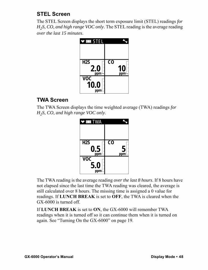
STEL ScreenThe STEL Screen displays the short term exposure limit (STEL) readings for H2S, CO, and high range VOC only. The STEL reading is the average reading over the last 15 minutes.
TWA ScreenThe TWA Screen displays the time weighted average (TWA) readings for H2S, CO, and high range VOC only.
The TWA reading is the average reading over the last 8 hours. If 8 hours have not elapsed since the last time the TWA reading was cleared, the average is still calculated over 8 hours. The missing time is assigned a 0 value for readings. If LUNCH BREAK is set to OFF, the TWA is cleared when the GX-6000 is turned off.If LUNCH BREAK is set to ON, the GX-6000 will remember TWA readings when it is turned off so it can continue them when it is turned on again. See “Turning On the GX-6000” on page 19.
STEL
H2S CO
ppm ppm
VOC
ppm
2.0 10
10.0
TWA
H2S CO
ppm ppm
VOC
ppm
0.5 5
5.0
GX-6000 Operator’s Manual Display Mode • 48
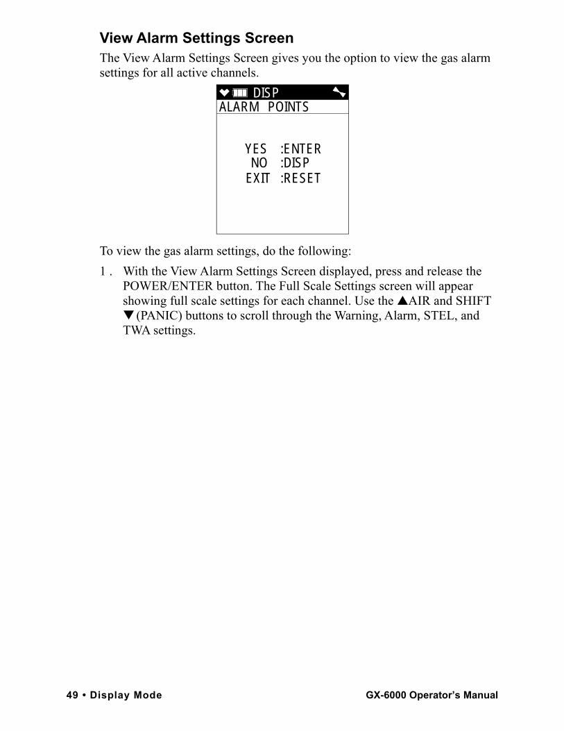
View Alarm Settings ScreenThe View Alarm Settings Screen gives you the option to view the gas alarm settings for all active channels.
To view the gas alarm settings, do the following:1 . With the View Alarm Settings Screen displayed, press and release the
POWER/ENTER button. The Full Scale Settings screen will appear showing full scale settings for each channel. Use the ▲AIR and SHIFT ▼ (PANIC) buttons to scroll through the Warning, Alarm, STEL, and TWA settings.
DISP ALARM POINTS
YES :ENTERNO :DISP
EXIT :RESET
49 • Display Mode GX-6000 Operator’s Manual
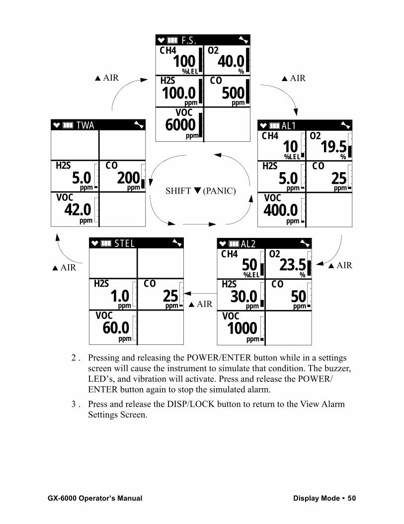
2 . Pressing and releasing the POWER/ENTER button while in a settings screen will cause the instrument to simulate that condition. The buzzer, LED’s, and vibration will activate. Press and release the POWER/ENTER button again to stop the simulated alarm.
3 . Press and release the DISP/LOCK button to return to the View Alarm Settings Screen.
F.S. CH4 O2
%LEL % H2S CO
ppm ppm
VOC
ppm
100 40.0
100.0 500
6000 AL1 CH4 O2
%LEL % H2S CO
ppm ppm
VOC
ppm
10 19.5
5.0 25
400.0
AL2 CH4 O2
%LEL % H2S CO
ppm ppm
VOC
ppm
50 23.5
30.0 50
1000
STEL
H2S CO
ppm ppm
VOC
ppm
1.0 25
60.0
TWA
H2S CO
ppm ppm
VOC
ppm
5.0 200
42.0
▲ AIR ▲ AIR
▲ AIR ▲ AIR
▲ AIR
SHIFT ▼ (PANIC)
GX-6000 Operator’s Manual Display Mode • 50
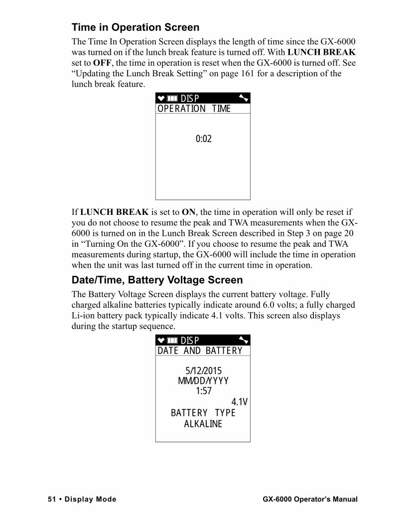
Time in Operation ScreenThe Time In Operation Screen displays the length of time since the GX-6000 was turned on if the lunch break feature is turned off. With LUNCH BREAK set to OFF, the time in operation is reset when the GX-6000 is turned off. See “Updating the Lunch Break Setting” on page 161 for a description of the lunch break feature.
If LUNCH BREAK is set to ON, the time in operation will only be reset if you do not choose to resume the peak and TWA measurements when the GX-6000 is turned on in the Lunch Break Screen described in Step 3 on page 20 in “Turning On the GX-6000”. If you choose to resume the peak and TWA measurements during startup, the GX-6000 will include the time in operation when the unit was last turned off in the current time in operation. Date/Time, Battery Voltage ScreenThe Battery Voltage Screen displays the current battery voltage. Fully charged alkaline batteries typically indicate around 6.0 volts; a fully charged Li-ion battery pack typically indicate 4.1 volts. This screen also displays during the startup sequence.
DISP OPERATION TIME
0:02
DISP DATE AND BATTERY
5/12/2015MM/DD/YYYY
1:57 4.1V
BATTERY TYPEALKALINE
51 • Display Mode GX-6000 Operator’s Manual
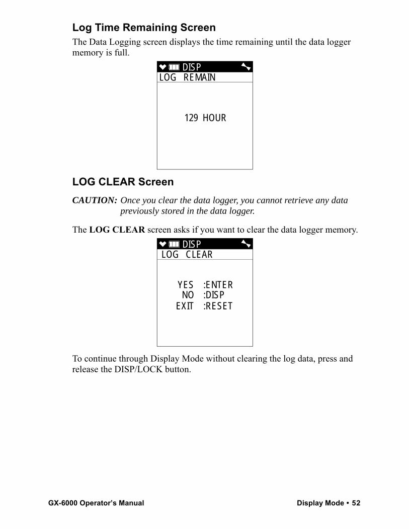
Log Time Remaining ScreenThe Data Logging screen displays the time remaining until the data logger memory is full.
LOG CLEAR ScreenCAUTION: Once you clear the data logger, you cannot retrieve any data
previously stored in the data logger.
The LOG CLEAR screen asks if you want to clear the data logger memory.
To continue through Display Mode without clearing the log data, press and release the DISP/LOCK button.
DISP LOG REMAIN
129 HOUR
DISP LOG CLEAR
YES :ENTERNO :DISP
EXIT :RESET
GX-6000 Operator’s Manual Display Mode • 52
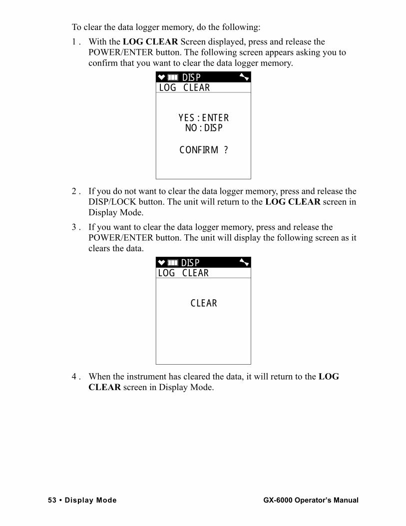
To clear the data logger memory, do the following:1 . With the LOG CLEAR Screen displayed, press and release the
POWER/ENTER button. The following screen appears asking you to confirm that you want to clear the data logger memory.
2 . If you do not want to clear the data logger memory, press and release the DISP/LOCK button. The unit will return to the LOG CLEAR screen in Display Mode.
3 . If you want to clear the data logger memory, press and release the POWER/ENTER button. The unit will display the following screen as it clears the data.
4 . When the instrument has cleared the data, it will return to the LOG CLEAR screen in Display Mode.
DISP LOG CLEAR
YES : ENTERNO : DISP
CONFIRM ?
DISP LOG CLEAR
CLEAR
53 • Display Mode GX-6000 Operator’s Manual
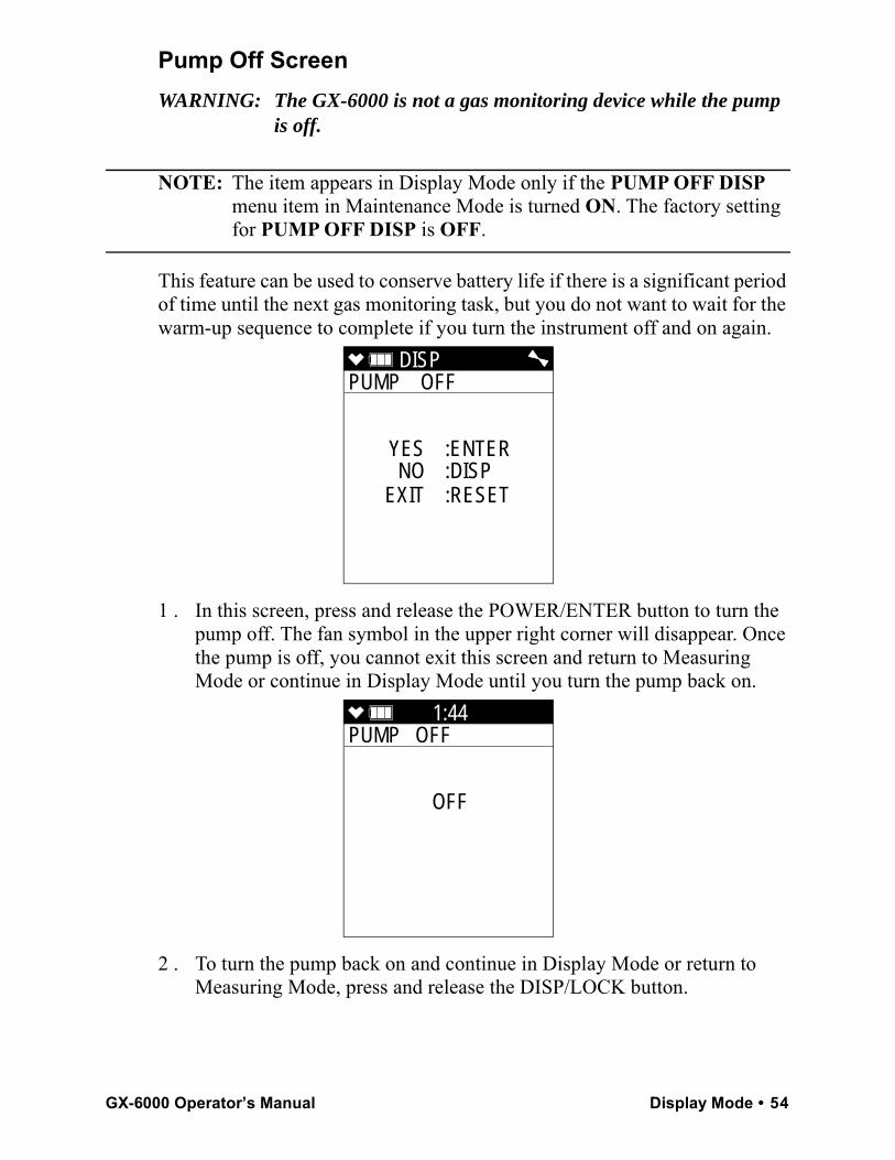
Pump Off ScreenWARNING: The GX-6000 is not a gas monitoring device while the pump
is off.
NOTE: The item appears in Display Mode only if the PUMP OFF DISP menu item in Maintenance Mode is turned ON. The factory setting for PUMP OFF DISP is OFF.
This feature can be used to conserve battery life if there is a significant period of time until the next gas monitoring task, but you do not want to wait for the warm-up sequence to complete if you turn the instrument off and on again.
1 . In this screen, press and release the POWER/ENTER button to turn the pump off. The fan symbol in the upper right corner will disappear. Once the pump is off, you cannot exit this screen and return to Measuring Mode or continue in Display Mode until you turn the pump back on.
2 . To turn the pump back on and continue in Display Mode or return to Measuring Mode, press and release the DISP/LOCK button.
DISP PUMP OFF
YES :ENTERNO :DISP
EXIT :RESET
1:44PUMP OFF
OFF
GX-6000 Operator’s Manual Display Mode • 54
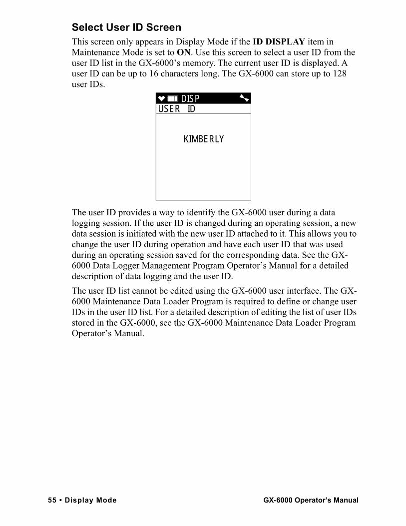
Select User ID ScreenThis screen only appears in Display Mode if the ID DISPLAY item in Maintenance Mode is set to ON. Use this screen to select a user ID from the user ID list in the GX-6000’s memory. The current user ID is displayed. A user ID can be up to 16 characters long. The GX-6000 can store up to 128 user IDs.
The user ID provides a way to identify the GX-6000 user during a data logging session. If the user ID is changed during an operating session, a new data session is initiated with the new user ID attached to it. This allows you to change the user ID during operation and have each user ID that was used during an operating session saved for the corresponding data. See the GX-6000 Data Logger Management Program Operator’s Manual for a detailed description of data logging and the user ID.The user ID list cannot be edited using the GX-6000 user interface. The GX-6000 Maintenance Data Loader Program is required to define or change user IDs in the user ID list. For a detailed description of editing the list of user IDs stored in the GX-6000, see the GX-6000 Maintenance Data Loader Program Operator’s Manual.
DISP USER ID
KIMBERLY
55 • Display Mode GX-6000 Operator’s Manual
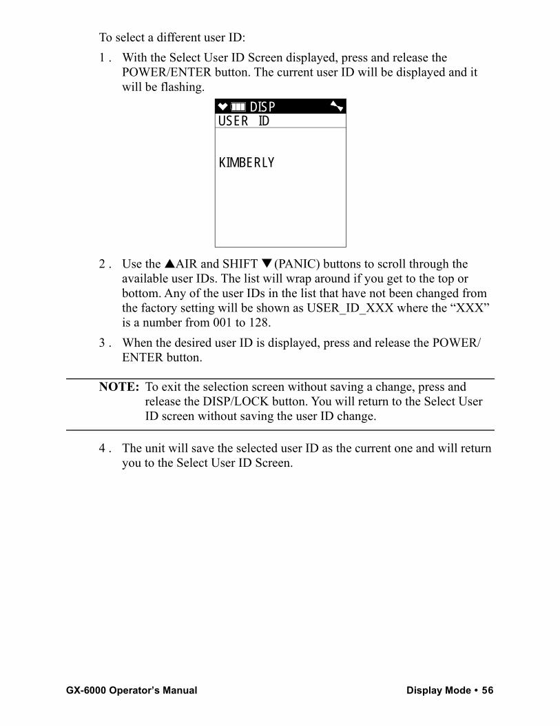
To select a different user ID:1 . With the Select User ID Screen displayed, press and release the
POWER/ENTER button. The current user ID will be displayed and it will be flashing.
2 . Use the ▲AIR and SHIFT ▼ (PANIC) buttons to scroll through the available user IDs. The list will wrap around if you get to the top or bottom. Any of the user IDs in the list that have not been changed from the factory setting will be shown as USER_ID_XXX where the “XXX” is a number from 001 to 128.
3 . When the desired user ID is displayed, press and release the POWER/ENTER button.
NOTE: To exit the selection screen without saving a change, press and release the DISP/LOCK button. You will return to the Select User ID screen without saving the user ID change.
4 . The unit will save the selected user ID as the current one and will return you to the Select User ID Screen.
DISP USER ID
KIMBERLY
GX-6000 Operator’s Manual Display Mode • 56
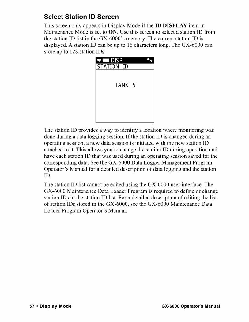
Select Station ID ScreenThis screen only appears in Display Mode if the ID DISPLAY item in Maintenance Mode is set to ON. Use this screen to select a station ID from the station ID list in the GX-6000’s memory. The current station ID is displayed. A station ID can be up to 16 characters long. The GX-6000 can store up to 128 station IDs.
The station ID provides a way to identify a location where monitoring was done during a data logging session. If the station ID is changed during an operating session, a new data session is initiated with the new station ID attached to it. This allows you to change the station ID during operation and have each station ID that was used during an operating session saved for the corresponding data. See the GX-6000 Data Logger Management Program Operator’s Manual for a detailed description of data logging and the station ID.The station ID list cannot be edited using the GX-6000 user interface. The GX-6000 Maintenance Data Loader Program is required to define or change station IDs in the station ID list. For a detailed description of editing the list of station IDs stored in the GX-6000, see the GX-6000 Maintenance Data Loader Program Operator’s Manual.
DISP STATION ID
TANK 5
57 • Display Mode GX-6000 Operator’s Manual
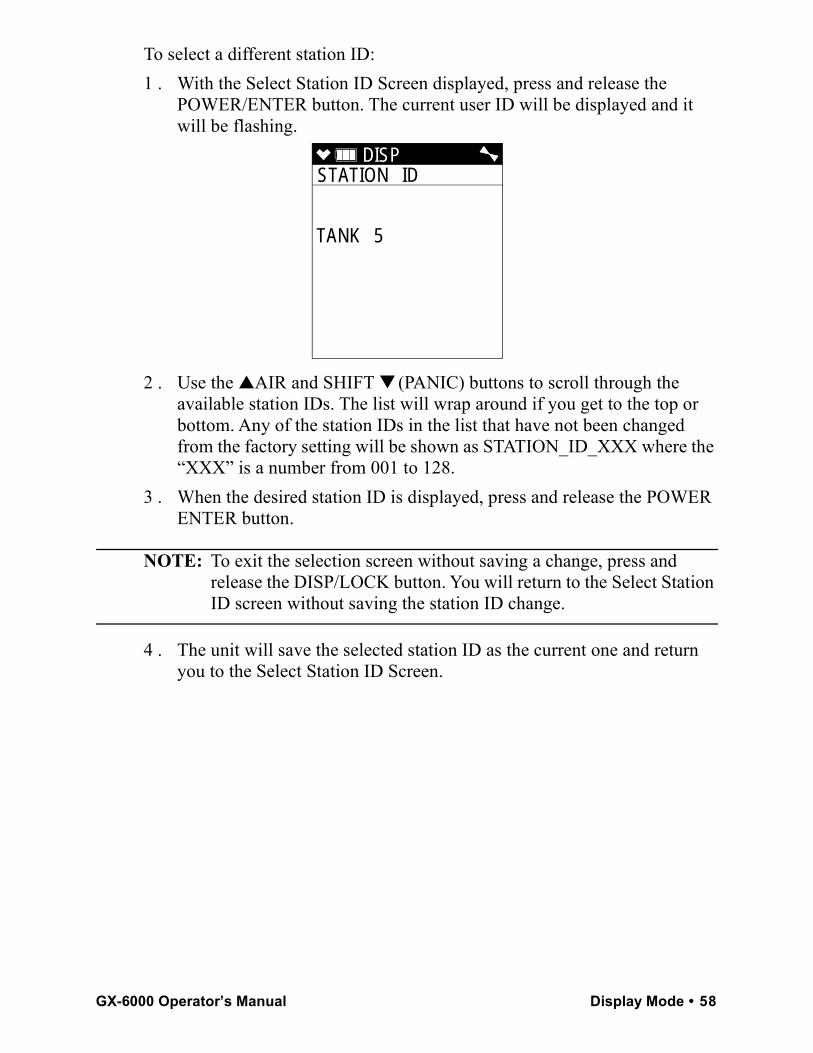
To select a different station ID:1 . With the Select Station ID Screen displayed, press and release the
POWER/ENTER button. The current user ID will be displayed and it will be flashing.
2 . Use the ▲AIR and SHIFT ▼ (PANIC) buttons to scroll through the available station IDs. The list will wrap around if you get to the top or bottom. Any of the station IDs in the list that have not been changed from the factory setting will be shown as STATION_ID_XXX where the “XXX” is a number from 001 to 128.
3 . When the desired station ID is displayed, press and release the POWER ENTER button.
NOTE: To exit the selection screen without saving a change, press and release the DISP/LOCK button. You will return to the Select Station ID screen without saving the station ID change.
4 . The unit will save the selected station ID as the current one and return you to the Select Station ID Screen.
DISP STATION ID
TANK 5
GX-6000 Operator’s Manual Display Mode • 58
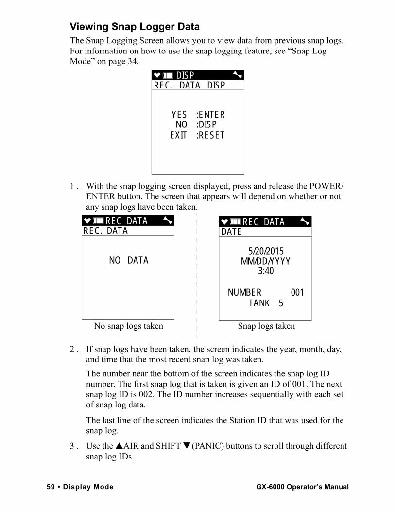
Viewing Snap Logger DataThe Snap Logging Screen allows you to view data from previous snap logs. For information on how to use the snap logging feature, see “Snap Log Mode” on page 34.
1 . With the snap logging screen displayed, press and release the POWER/ENTER button. The screen that appears will depend on whether or not any snap logs have been taken.
2 . If snap logs have been taken, the screen indicates the year, month, day, and time that the most recent snap log was taken. The number near the bottom of the screen indicates the snap log ID number. The first snap log that is taken is given an ID of 001. The next snap log ID is 002. The ID number increases sequentially with each set of snap log data.
The last line of the screen indicates the Station ID that was used for the snap log.
3 . Use the ▲AIR and SHIFT ▼ (PANIC) buttons to scroll through different snap log IDs.
DISP REC. DATA DISP
YES :ENTERNO :DISP
EXIT :RESET
REC DATA REC. DATA
NO DATA
REC DATA DATE
5/20/2015MM/DD/YYYY
3:40
NUMBER 001TANK 5
No snap logs taken Snap logs taken
59 • Display Mode GX-6000 Operator’s Manual
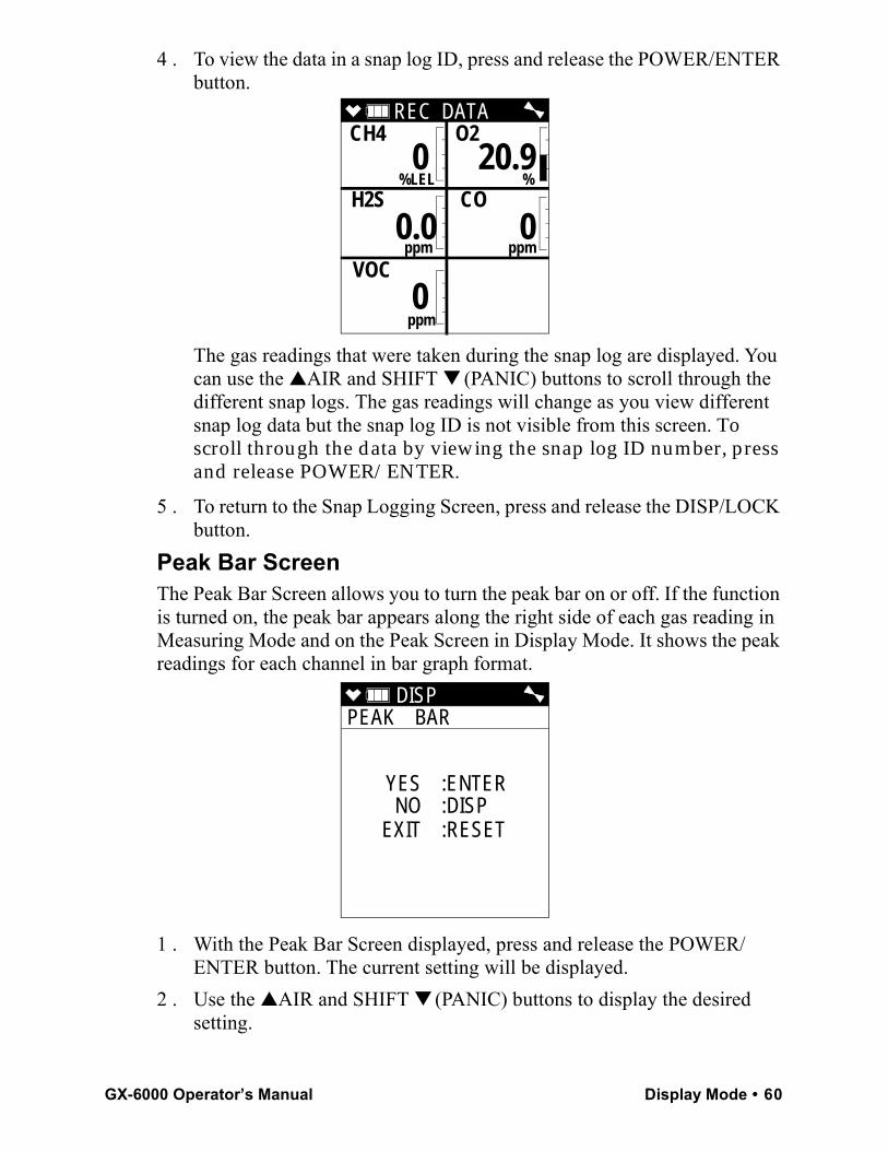
4 . To view the data in a snap log ID, press and release the POWER/ENTER button.
The gas readings that were taken during the snap log are displayed. You can use the ▲AIR and SHIFT ▼ (PANIC) buttons to scroll through the different snap logs. The gas readings will change as you view different snap log data but the snap log ID is not visible from this screen. To scroll through the data by viewing the snap log ID number, press and release POWER/ENTER.
5 . To return to the Snap Logging Screen, press and release the DISP/LOCK button.
Peak Bar ScreenThe Peak Bar Screen allows you to turn the peak bar on or off. If the function is turned on, the peak bar appears along the right side of each gas reading in Measuring Mode and on the Peak Screen in Display Mode. It shows the peak readings for each channel in bar graph format.
1 . With the Peak Bar Screen displayed, press and release the POWER/ENTER button. The current setting will be displayed.
2 . Use the ▲AIR and SHIFT ▼ (PANIC) buttons to display the desired setting.
REC DATA CH4 O2
%LEL % H2S CO
ppm ppm
VOC
ppm
0 20.9
0.0 0
0
DISP PEAK BAR
YES :ENTERNO :DISP
EXIT :RESET
GX-6000 Operator’s Manual Display Mode • 60
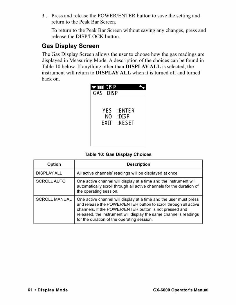
3 . Press and release the POWER/ENTER button to save the setting and return to the Peak Bar Screen.To return to the Peak Bar Screen without saving any changes, press and release the DISP/LOCK button.
Gas Display ScreenThe Gas Display Screen allows the user to choose how the gas readings are displayed in Measuring Mode. A description of the choices can be found in Table 10 below. If anything other than DISPLAY ALL is selected, the instrument will return to DISPLAY ALL when it is turned off and turned back on.
Table 10: Gas Display Choices
Option Description
DISPLAY ALL All active channels’ readings will be displayed at once
SCROLL AUTO One active channel will display at a time and the instrument will automatically scroll through all active channels for the duration of the operating session.
SCROLL MANUAL One active channel will display at a time and the user must press and release the POWER/ENTER button to scroll through all active channels. If the POWER/ENTER button is not pressed and released, the instrument will display the same channel’s readings for the duration of the operating session.
DISP GAS DISP
YES :ENTERNO :DISP
EXIT :RESET
61 • Display Mode GX-6000 Operator’s Manual
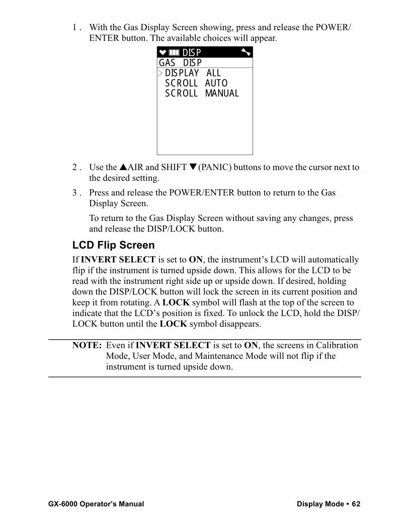
1 . With the Gas Display Screen showing, press and release the POWER/ENTER button. The available choices will appear.
2 . Use the ▲AIR and SHIFT ▼ (PANIC) buttons to move the cursor next to the desired setting.
3 . Press and release the POWER/ENTER button to return to the Gas Display Screen.To return to the Gas Display Screen without saving any changes, press and release the DISP/LOCK button.
LCD Flip ScreenIf INVERT SELECT is set to ON, the instrument’s LCD will automatically flip if the instrument is turned upside down. This allows for the LCD to be read with the instrument right side up or upside down. If desired, holding down the DISP/LOCK button will lock the screen in its current position and keep it from rotating. A LOCK symbol will flash at the top of the screen to indicate that the LCD’s position is fixed. To unlock the LCD, hold the DISP/LOCK button until the LOCK symbol disappears.
NOTE: Even if INVERT SELECT is set to ON, the screens in Calibration Mode, User Mode, and Maintenance Mode will not flip if the instrument is turned upside down.
DISP GAS DISP
DISPLAY ALL SCROLL AUTO SCROLL MANUAL
GX-6000 Operator’s Manual Display Mode • 62
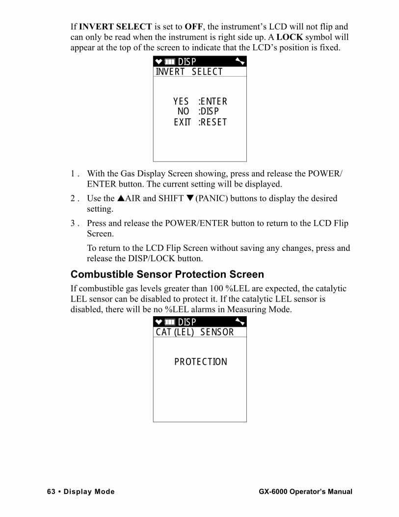
If INVERT SELECT is set to OFF, the instrument’s LCD will not flip and can only be read when the instrument is right side up. A LOCK symbol will appear at the top of the screen to indicate that the LCD’s position is fixed.
1 . With the Gas Display Screen showing, press and release the POWER/ENTER button. The current setting will be displayed.
2 . Use the ▲AIR and SHIFT ▼ (PANIC) buttons to display the desired setting.
3 . Press and release the POWER/ENTER button to return to the LCD Flip Screen.To return to the LCD Flip Screen without saving any changes, press and release the DISP/LOCK button.
Combustible Sensor Protection ScreenIf combustible gas levels greater than 100 %LEL are expected, the catalytic LEL sensor can be disabled to protect it. If the catalytic LEL sensor is disabled, there will be no %LEL alarms in Measuring Mode.
DISP INVERT SELECT
YES :ENTERNO :DISP
EXIT :RESET
DISP CAT (LEL) SENSOR
PROTECTION
63 • Display Mode GX-6000 Operator’s Manual
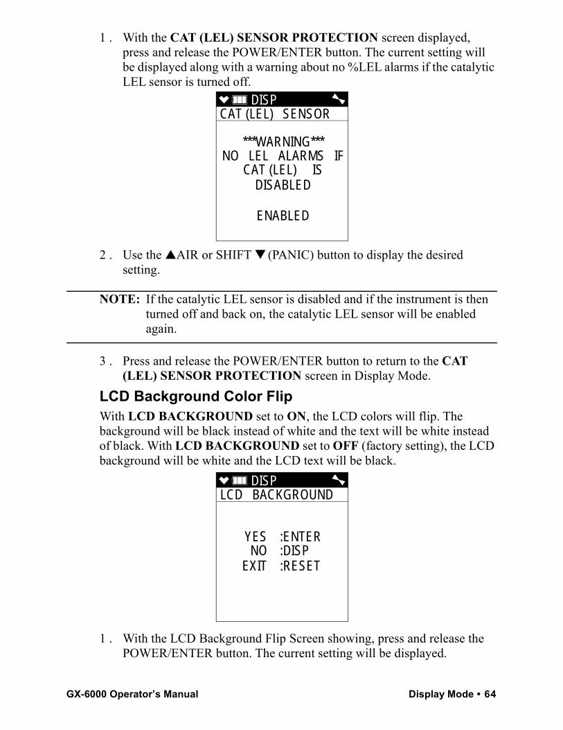
1 . With the CAT (LEL) SENSOR PROTECTION screen displayed, press and release the POWER/ENTER button. The current setting will be displayed along with a warning about no %LEL alarms if the catalytic LEL sensor is turned off.
2 . Use the ▲AIR or SHIFT ▼ (PANIC) button to display the desired setting.
NOTE: If the catalytic LEL sensor is disabled and if the instrument is then turned off and back on, the catalytic LEL sensor will be enabled again.
3 . Press and release the POWER/ENTER button to return to the CAT (LEL) SENSOR PROTECTION screen in Display Mode.
LCD Background Color FlipWith LCD BACKGROUND set to ON, the LCD colors will flip. The background will be black instead of white and the text will be white instead of black. With LCD BACKGROUND set to OFF (factory setting), the LCD background will be white and the LCD text will be black.
1 . With the LCD Background Flip Screen showing, press and release the POWER/ENTER button. The current setting will be displayed.
DISP CAT (LEL) SENSOR
***WARNING***NO LEL ALARMS IF
CAT (LEL) ISDISABLED
ENABLED
DISP LCD BACKGROUND
YES :ENTERNO :DISP
EXIT :RESET
GX-6000 Operator’s Manual Display Mode • 64
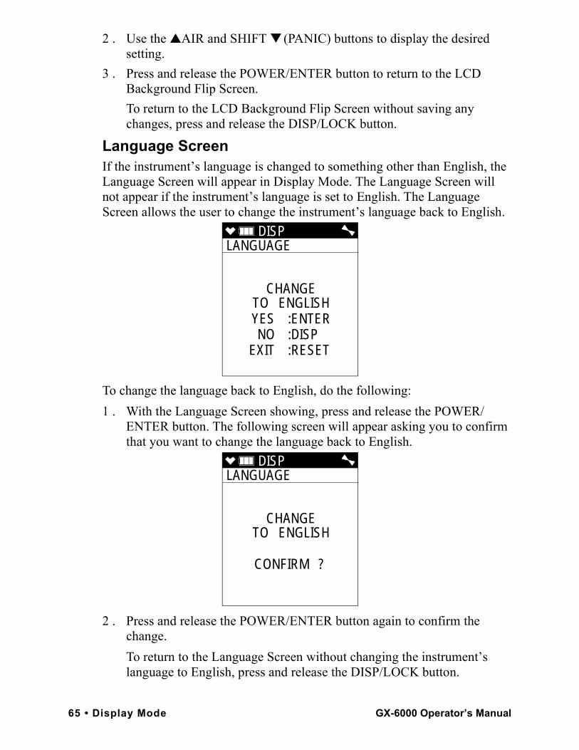
2 . Use the ▲AIR and SHIFT ▼ (PANIC) buttons to display the desired setting.
3 . Press and release the POWER/ENTER button to return to the LCD Background Flip Screen.To return to the LCD Background Flip Screen without saving any changes, press and release the DISP/LOCK button.
Language ScreenIf the instrument’s language is changed to something other than English, the Language Screen will appear in Display Mode. The Language Screen will not appear if the instrument’s language is set to English. The Language Screen allows the user to change the instrument’s language back to English.
To change the language back to English, do the following:1 . With the Language Screen showing, press and release the POWER/
ENTER button. The following screen will appear asking you to confirm that you want to change the language back to English.
2 . Press and release the POWER/ENTER button again to confirm the change.To return to the Language Screen without changing the instrument’s language to English, press and release the DISP/LOCK button.
DISP LANGUAGE
CHANGETO ENGLISHYES :ENTERNO :DISP
EXIT :RESET
DISP LANGUAGE
CHANGETO ENGLISH
CONFIRM ?
65 • Display Mode GX-6000 Operator’s Manual
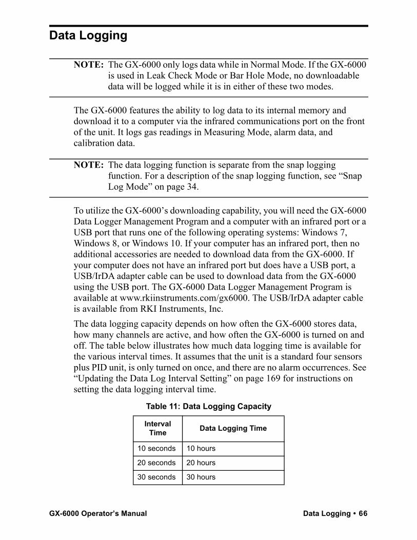
Data Logging
NOTE: The GX-6000 only logs data while in Normal Mode. If the GX-6000 is used in Leak Check Mode or Bar Hole Mode, no downloadable data will be logged while it is in either of these two modes.
The GX-6000 features the ability to log data to its internal memory and download it to a computer via the infrared communications port on the front of the unit. It logs gas readings in Measuring Mode, alarm data, and calibration data.
NOTE: The data logging function is separate from the snap logging function. For a description of the snap logging function, see “Snap Log Mode” on page 34.
To utilize the GX-6000’s downloading capability, you will need the GX-6000 Data Logger Management Program and a computer with an infrared port or a USB port that runs one of the following operating systems: Windows 7, Windows 8, or Windows 10. If your computer has an infrared port, then no additional accessories are needed to download data from the GX-6000. If your computer does not have an infrared port but does have a USB port, a USB/IrDA adapter cable can be used to download data from the GX-6000 using the USB port. The GX-6000 Data Logger Management Program is available at www.rkiinstruments.com/gx6000. The USB/IrDA adapter cable is available from RKI Instruments, Inc.The data logging capacity depends on how often the GX-6000 stores data, how many channels are active, and how often the GX-6000 is turned on and off. The table below illustrates how much data logging time is available for the various interval times. It assumes that the unit is a standard four sensors plus PID unit, is only turned on once, and there are no alarm occurrences. See “Updating the Data Log Interval Setting” on page 169 for instructions on setting the data logging interval time.
Table 11: Data Logging Capacity
Interval Time Data Logging Time
10 seconds 10 hours
20 seconds 20 hours
30 seconds 30 hours
GX-6000 Operator’s Manual Data Logging • 66
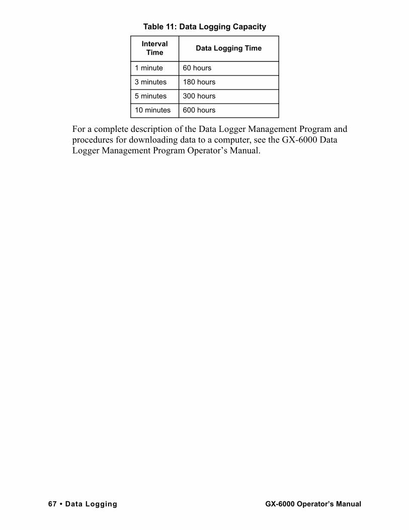
For a complete description of the Data Logger Management Program and procedures for downloading data to a computer, see the GX-6000 Data Logger Management Program Operator’s Manual.
1 minute 60 hours
3 minutes 180 hours
5 minutes 300 hours
10 minutes 600 hours
Table 11: Data Logging Capacity
Interval Time Data Logging Time
67 • Data Logging GX-6000 Operator’s Manual
Chapter 4: Calibration Mode
OverviewThis section describes the GX-6000 in Calibration Mode. In Calibration Mode, you can move through a menu of screens to do the following:• Perform a fresh air (zero) adjustment• Perform a span adjustment on all channels simultaneously using
auto calibration• Perform a span adjustment on one channel at a time using single
calibration• Perform a bump test
NOTE: You can set up the GX-6000 to alert you during the startup sequence when calibration is due. See “Updating the Calibration Reminder Setting” on page 149.
CAUTION: BEFORE EACH DAY’S USAGE, SENSITIVITY IN THE%LEL RANGE MUST BE TESTED ON A KNOWN CONCENTRATION OF THE COMBUSTIBLE TARGET GAS, METHANE, EQUIVALENT TO 25 - 50% OF FULL SCALE CONCENTRATION (the %LEL full scale is 100 %LEL). ACCURACY MUST BE WITHIN -0 to + 20% OF ACTUAL. ACCURACY MAY BE CORRECTED BY FOLLOWING THE CALIBRATION INSTRUCTIONS FOR THE COMBUSTIBLE CHANNEL BELOW.
If the combustible channel passes the above response test and does not require calibration, the unit should still be calibrated periodically. The optimum frequency of calibration depends heavily on how the GX-6000 is used. For example, instruments used daily may need to be calibrated weekly or monthly, while instruments that are used only a few times a year may need to be calibrated before each use. Typical calibration frequencies range from monthly to quarterly. Make sure to perform the combustible channel response test as described above and make sure to develop a calibration schedule tailored to your application that takes this test and required calibration resulting from this test into account.
GX-6000 Operator’s Manual Overview • 68
Calibration Supplies and Equipment
To calibrate the GX-6000, you will need:• Known calibrating samples of the gases being detected. The combustible
and toxic gas samples should have concentrations between 10 and 50% of the full scale value. For example, if you are calibrating the catalytic combustible gas channel, your calibration cylinder should have a combustible gas concentration between 10% LEL and 50% LEL. An oxygen-free source, such as 100% nitrogen is recommended for setting the oxygen zero.
CAUTION: When using auto calibration, although the GX-6000 can be calibrated with an oxygen concentration of up to 19.5%, RKI Instruments, Inc. recommends that the multi-gas cylinder have an oxygen concentration in the range of 10% - 16% oxygen.
• A demand-flow regulator to provide adequate sample gas flow
NOTE: RKI Instruments, Inc. recommends that you dedicate a regulator for use with chlorine (Cl2) gas and that you do not use that dedicated regulator for any other gases, particularly hydrogen sulfide (H2S).
• Non-absorbent tubing
WARNING: If you are using a calibration kit that includes a gas bag and a fixed flow regulator or dispensing valve, do not apply gas directly to the GX-6000 with the regulator or dispensing valve or damage to the pump will result.
To calibrate the %LEL, oxygen, CO, H2S, and PID sensors at the same time, automatically, with no need for a zero-oxygen source, you can use the auto calibration feature with either a 5-gas cylinder or a 4-gas cylinder and a PID cylinder. This chapter includes instructions for both scenarios along with instructions for calibrating one channel at a time using single calibration.
69 • Calibration Supplies and Equipment GX-6000 Operator’s Manual
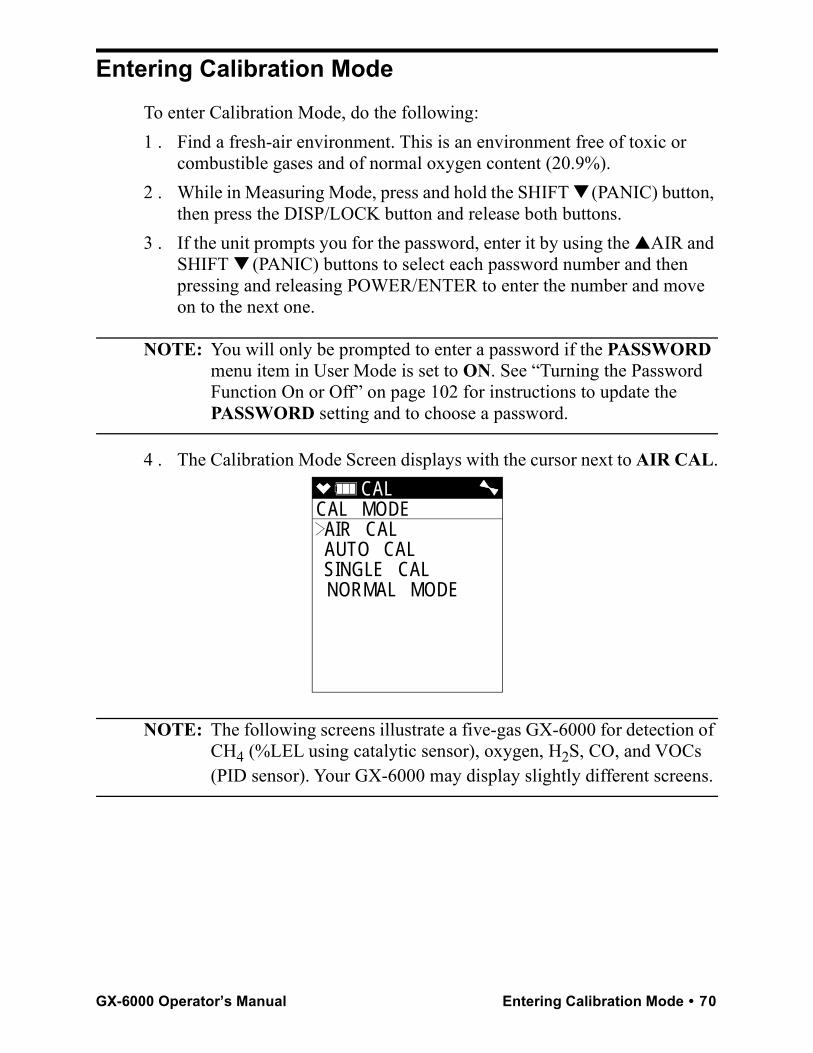
Entering Calibration ModeTo enter Calibration Mode, do the following:1 . Find a fresh-air environment. This is an environment free of toxic or
combustible gases and of normal oxygen content (20.9%).2 . While in Measuring Mode, press and hold the SHIFT ▼ (PANIC) button,
then press the DISP/LOCK button and release both buttons.3 . If the unit prompts you for the password, enter it by using the ▲AIR and
SHIFT ▼ (PANIC) buttons to select each password number and then pressing and releasing POWER/ENTER to enter the number and move on to the next one.
NOTE: You will only be prompted to enter a password if the PASSWORD menu item in User Mode is set to ON. See “Turning the Password Function On or Off” on page 102 for instructions to update the PASSWORD setting and to choose a password.
4 . The Calibration Mode Screen displays with the cursor next to AIR CAL.
NOTE: The following screens illustrate a five-gas GX-6000 for detection of CH4 (%LEL using catalytic sensor), oxygen, H2S, CO, and VOCs (PID sensor). Your GX-6000 may display slightly different screens.
CAL CAL MODE AIR CAL AUTO CAL SINGLE CAL NORMAL MODE
GX-6000 Operator’s Manual Entering Calibration Mode • 70
Calibrating Using the Auto Calibration Method
This method allows you to calibrate the CH4 (%LEL sensor), oxygen, H2S, CO, and VOC (PID sensor) sensors simultaneously. It is designed for use with either the RKI 5-gas calibration cylinder (high range PID only) or an RKI 4-gas cylinder and an RKI PID cylinder and is the quickest and easiest method to calibrate the GX-6000. See Table 16 on page 137 for available cylinders. Make sure your calibration cylinder is appropriate for the PID detection range.
NOTE: The 5-gas calibration cylinder that includes LEL CH4/O2/CO/H2S/isobutylene is a proprietary gas mix developed by RKI Instruments, Inc. for calibrating a PID sensor in the presence of the other gases during an auto calibration. It can also be used for a single calibration of a PID sensor. Do not use a similar gas mix provided by any other manufacturer when calibrating a PID channel. Use of a gas mix from another manufacturer that includes isobutylene and these other gases will result in an inaccurate calibration.
Setting the Fresh Air Reading1 . Find a fresh-air environment. This is an environment free of toxic or
combustible gases and of normal oxygen content (20.9%).2 . While in Measuring Mode, press and hold the SHIFT ▼ (PANIC) button,
then press the DISP/LOCK button and release both buttons.3 . If the unit prompts you for the password, enter it by using the ▲AIR and
SHIFT ▼ (PANIC) buttons to select each password number and then pressing and releasing POWER/ENTER to enter the number and move on to the next one.
NOTE: You will only be prompted to enter a password if the PASSWORD menu item in User Mode is set to ON. See “Turning the Password Function On or Off” on page 102 for instructions to update the PASSWORD setting and to choose a password.
71 • Calibrating Using the Auto Calibration Method GX-6000 Operator’s Manual
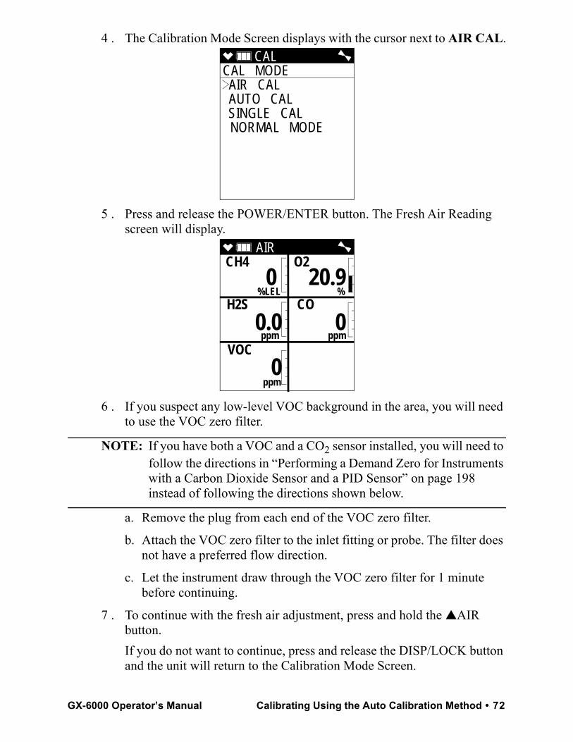
4 . The Calibration Mode Screen displays with the cursor next to AIR CAL.
5 . Press and release the POWER/ENTER button. The Fresh Air Reading screen will display.
6 . If you suspect any low-level VOC background in the area, you will need to use the VOC zero filter.
NOTE: If you have both a VOC and a CO2 sensor installed, you will need to follow the directions in “Performing a Demand Zero for Instruments with a Carbon Dioxide Sensor and a PID Sensor” on page 198 instead of following the directions shown below.
a. Remove the plug from each end of the VOC zero filter.
b. Attach the VOC zero filter to the inlet fitting or probe. The filter does not have a preferred flow direction.
c. Let the instrument draw through the VOC zero filter for 1 minute before continuing.
7 . To continue with the fresh air adjustment, press and hold the ▲AIR button.If you do not want to continue, press and release the DISP/LOCK button and the unit will return to the Calibration Mode Screen.
CAL CAL MODE AIR CAL AUTO CAL SINGLE CAL NORMAL MODE
AIR CH4 O2
%LEL % H2S CO
ppm ppm
VOC
ppm
0 20.9
0.0 0
0
GX-6000 Operator’s Manual Calibrating Using the Auto Calibration Method • 72
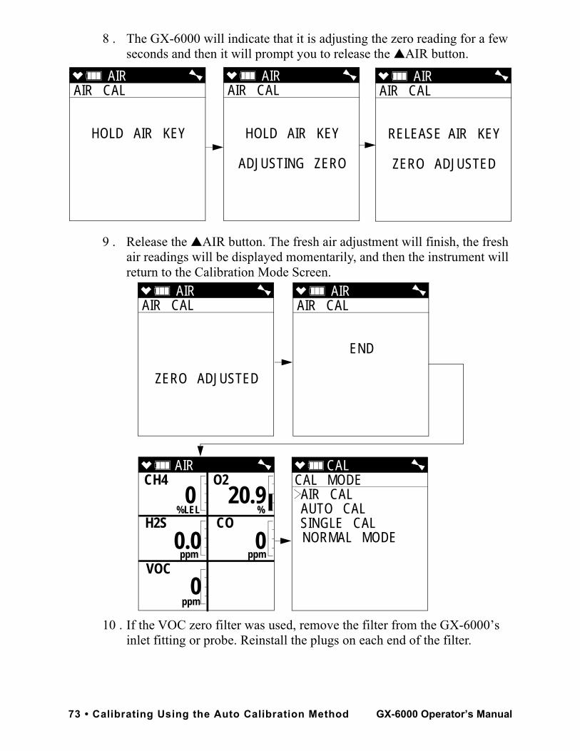
8 . The GX-6000 will indicate that it is adjusting the zero reading for a few seconds and then it will prompt you to release the ▲AIR button.
9 . Release the ▲AIR button. The fresh air adjustment will finish, the fresh air readings will be displayed momentarily, and then the instrument will return to the Calibration Mode Screen.
10 . If the VOC zero filter was used, remove the filter from the GX-6000’s inlet fitting or probe. Reinstall the plugs on each end of the filter.
AIR AIR CAL
HOLD AIR KEY
AIR AIR CAL
HOLD AIR KEY
ADJUSTING ZERO
AIR AIR CAL
RELEASE AIR KEY
ZERO ADJUSTED
AIR AIR CAL
ZERO ADJUSTED
CAL CAL MODE AIR CAL AUTO CAL SINGLE CAL NORMAL MODE
AIR AIR CAL
END
AIR CH4 O2
%LEL % H2S CO
ppm ppm
VOC
ppm
0 20.9
0.0 0
0
73 • Calibrating Using the Auto Calibration Method GX-6000 Operator’s Manual
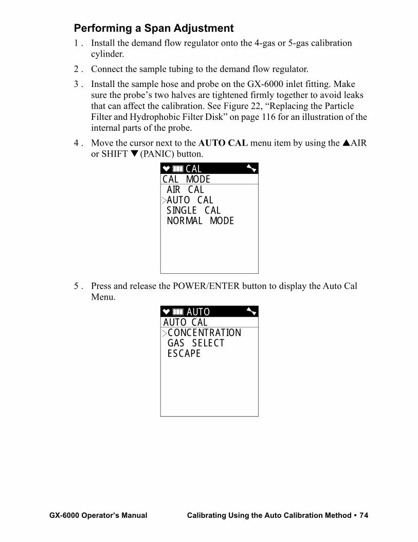
Performing a Span Adjustment1 . Install the demand flow regulator onto the 4-gas or 5-gas calibration
cylinder.2 . Connect the sample tubing to the demand flow regulator.3 . Install the sample hose and probe on the GX-6000 inlet fitting. Make
sure the probe’s two halves are tightened firmly together to avoid leaks that can affect the calibration. See Figure 22, “Replacing the Particle Filter and Hydrophobic Filter Disk” on page 116 for an illustration of the internal parts of the probe.
4 . Move the cursor next to the AUTO CAL menu item by using the ▲AIR or SHIFT ▼ (PANIC) button.
5 . Press and release the POWER/ENTER button to display the Auto Cal Menu.
CAL CAL MODE AIR CAL AUTO CAL SINGLE CAL NORMAL MODE
AUTO AUTO CAL CONCENTRATION GAS SELECT ESCAPE
GX-6000 Operator’s Manual Calibrating Using the Auto Calibration Method • 74
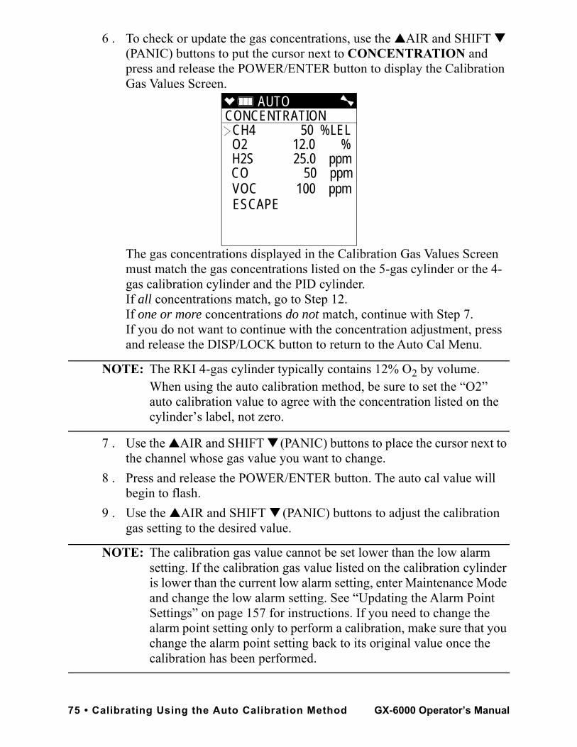
6 . To check or update the gas concentrations, use the ▲AIR and SHIFT ▼ (PANIC) buttons to put the cursor next to CONCENTRATION and press and release the POWER/ENTER button to display the Calibration Gas Values Screen.
The gas concentrations displayed in the Calibration Gas Values Screen must match the gas concentrations listed on the 5-gas cylinder or the 4-gas calibration cylinder and the PID cylinder.If all concentrations match, go to Step 12.If one or more concentrations do not match, continue with Step 7.If you do not want to continue with the concentration adjustment, press and release the DISP/LOCK button to return to the Auto Cal Menu.
NOTE: The RKI 4-gas cylinder typically contains 12% O2 by volume. When using the auto calibration method, be sure to set the “O2” auto calibration value to agree with the concentration listed on the cylinder’s label, not zero.
7 . Use the ▲AIR and SHIFT ▼ (PANIC) buttons to place the cursor next to the channel whose gas value you want to change.
8 . Press and release the POWER/ENTER button. The auto cal value will begin to flash.
9 . Use the ▲AIR and SHIFT ▼ (PANIC) buttons to adjust the calibration gas setting to the desired value.
NOTE: The calibration gas value cannot be set lower than the low alarm setting. If the calibration gas value listed on the calibration cylinder is lower than the current low alarm setting, enter Maintenance Mode and change the low alarm setting. See “Updating the Alarm Point Settings” on page 157 for instructions. If you need to change the alarm point setting only to perform a calibration, make sure that you change the alarm point setting back to its original value once the calibration has been performed.
AUTO CONCENTRATION CH4 50 %LEL O2 12.0 % H2S 25.0 ppm CO 50 ppm VOC 100 ppmESCAPE
75 • Calibrating Using the Auto Calibration Method GX-6000 Operator’s Manual
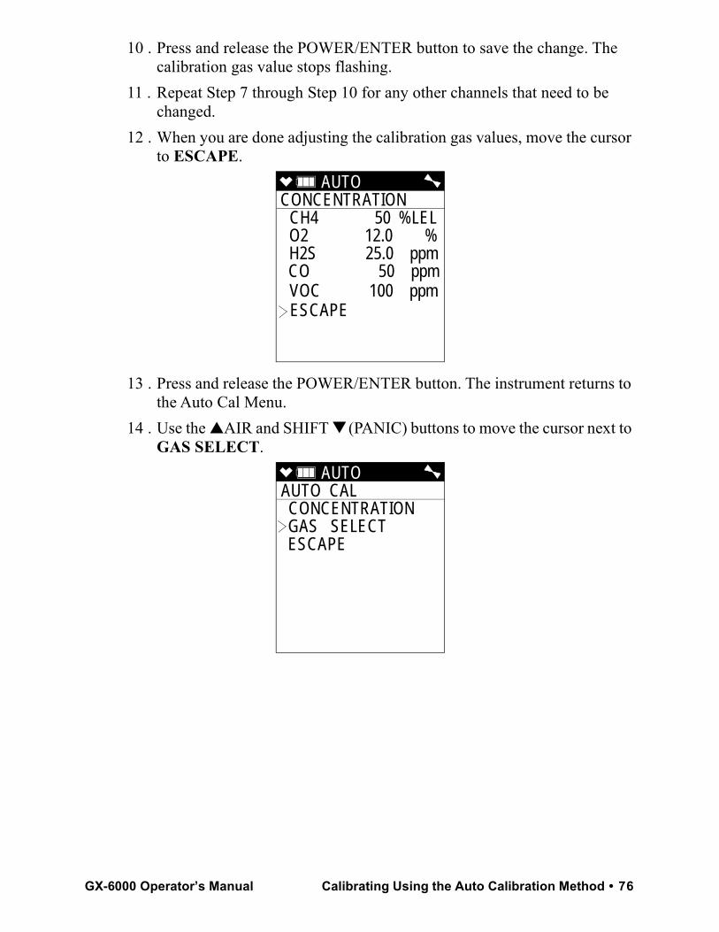
10 . Press and release the POWER/ENTER button to save the change. The calibration gas value stops flashing.
11 . Repeat Step 7 through Step 10 for any other channels that need to be changed.
12 . When you are done adjusting the calibration gas values, move the cursor to ESCAPE.
13 . Press and release the POWER/ENTER button. The instrument returns to the Auto Cal Menu.
14 . Use the ▲AIR and SHIFT ▼ (PANIC) buttons to move the cursor next to GAS SELECT.
AUTO CONCENTRATION CH4 50 %LEL O2 12.0 % H2S 25.0 ppm CO 50 ppm VOC 100 ppmESCAPE
AUTO AUTO CAL CONCENTRATION GAS SELECT ESCAPE
GX-6000 Operator’s Manual Calibrating Using the Auto Calibration Method • 76
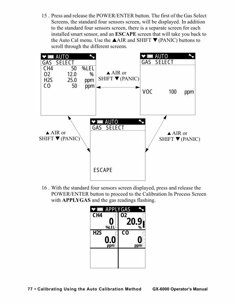
15 . Press and release the POWER/ENTER button. The first of the Gas Select Screens, the standard four sensors screen, will be displayed. In addition to the standard four sensors screen, there is a separate screen for each installed smart sensor, and an ESCAPE screen that will take you back to the Auto Cal menu. Use the ▲AIR and SHIFT ▼ (PANIC) buttons to scroll through the different screens.
16 . With the standard four sensors screen displayed, press and release the POWER/ENTER button to proceed to the Calibration In Process Screen with APPLYGAS and the gas readings flashing.
AUTO GAS SELECT CH4 50 %LELO2 12.0 %H2S 25.0 ppmCO 50 ppm
AUTO GAS SELECT
VOC 100 ppm
AUTO GAS SELECT
ESCAPE
▲ AIR orSHIFT ▼ (PANIC)
▲ AIR orSHIFT ▼ (PANIC)
▲ AIR orSHIFT ▼ (PANIC)
APPLYGASCH4 O2
%LEL % H2S CO
ppm ppm
0 20.9
0.0 0
77 • Calibrating Using the Auto Calibration Method GX-6000 Operator’s Manual
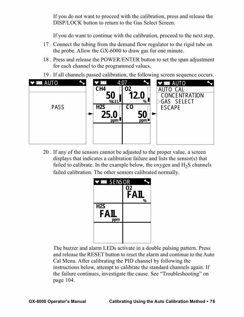
If you do not want to proceed with the calibration, press and release the DISP/LOCK button to return to the Gas Select Screen.
If you do want to continue with the calibration, proceed to the next step.17 . Connect the tubing from the demand flow regulator to the rigid tube on
the probe. Allow the GX-6000 to draw gas for one minute.18 . Press and release the POWER/ENTER button to set the span adjustment
for each channel to the programmed values.19 . If all channels passed calibration, the following screen sequence occurs.
20 . If any of the sensors cannot be adjusted to the proper value, a screen displays that indicates a calibration failure and lists the sensor(s) that failed to calibrate. In the example below, the oxygen and H2S channels failed calibration. The other sensors calibrated normally.
The buzzer and alarm LEDs activate in a double pulsing pattern. Press and release the RESET button to reset the alarm and continue to the Auto Cal Menu. After calibrating the PID channel by following the instructions below, attempt to calibrate the standard channels again. If the failure continues, investigate the cause. See “Troubleshooting” on page 104.
AUTO
PASS
AUTO AUTO CAL CONCENTRATION GAS SELECT ESCAPE
4:07CH4 O2
%LEL % H2S CO
ppm ppm
50 12.0
25.0 50
SENSOR O2
%
H2S
ppm
FAIL
FAIL
GX-6000 Operator’s Manual Calibrating Using the Auto Calibration Method • 78
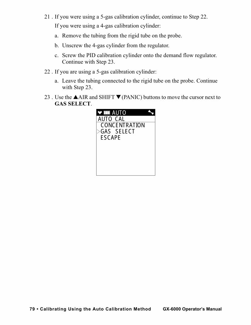
21 . If you were using a 5-gas calibration cylinder, continue to Step 22.If you were using a 4-gas calibration cylinder:
a. Remove the tubing from the rigid tube on the probe.
b. Unscrew the 4-gas cylinder from the regulator.
c. Screw the PID calibration cylinder onto the demand flow regulator. Continue with Step 23.
22 . If you are using a 5-gas calibration cylinder: a. Leave the tubing connected to the rigid tube on the probe. Continue
with Step 23.
23 . Use the ▲AIR and SHIFT ▼ (PANIC) buttons to move the cursor next to GAS SELECT.
AUTO AUTO CAL CONCENTRATION GAS SELECT ESCAPE
79 • Calibrating Using the Auto Calibration Method GX-6000 Operator’s Manual
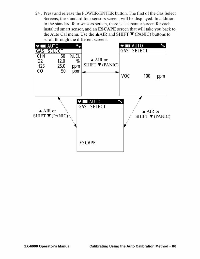
24 . Press and release the POWER/ENTER button. The first of the Gas Select Screens, the standard four sensors screen, will be displayed. In addition to the standard four sensors screen, there is a separate screen for each installed smart sensor, and an ESCAPE screen that will take you back to the Auto Cal menu. Use the ▲AIR and SHIFT ▼ (PANIC) buttons to scroll through the different screens.
AUTO GAS SELECT CH4 50 %LELO2 12.0 %H2S 25.0 ppmCO 50 ppm
AUTO GAS SELECT
VOC 100 ppm
AUTO GAS SELECT
ESCAPE
▲ AIR orSHIFT ▼ (PANIC)
▲ AIR orSHIFT ▼ (PANIC)
▲ AIR orSHIFT ▼ (PANIC)
GX-6000 Operator’s Manual Calibrating Using the Auto Calibration Method • 80
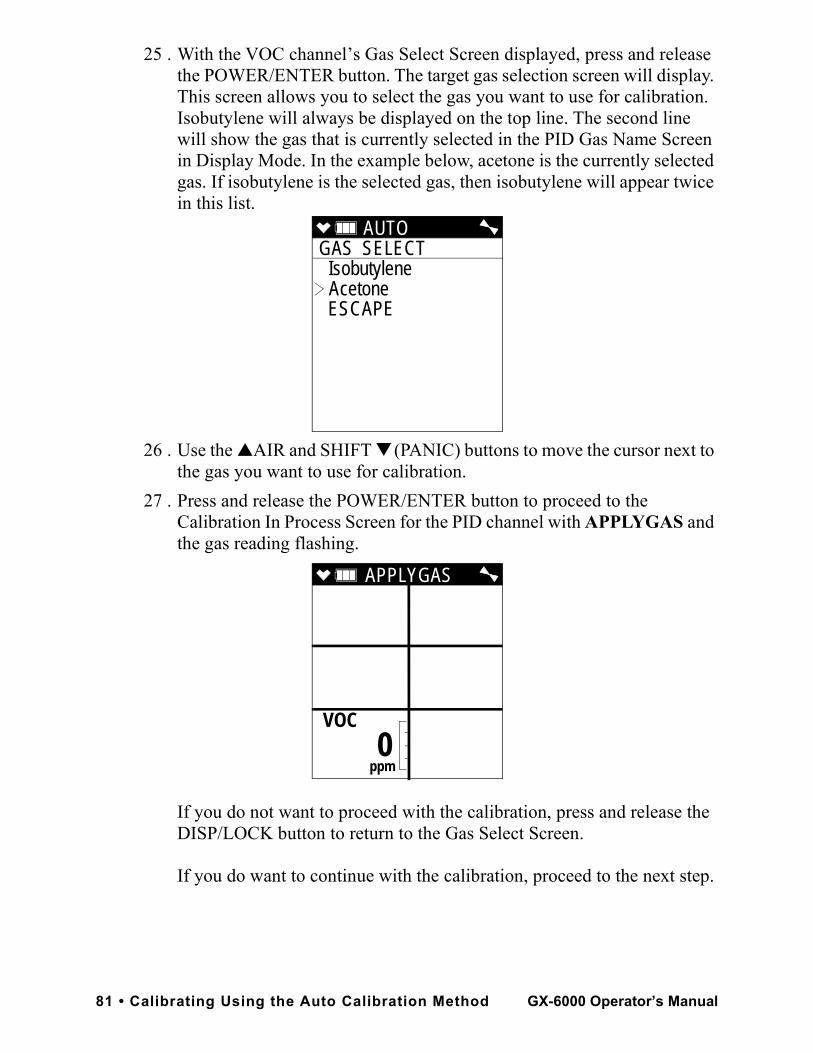
25 . With the VOC channel’s Gas Select Screen displayed, press and release the POWER/ENTER button. The target gas selection screen will display. This screen allows you to select the gas you want to use for calibration. Isobutylene will always be displayed on the top line. The second line will show the gas that is currently selected in the PID Gas Name Screen in Display Mode. In the example below, acetone is the currently selected gas. If isobutylene is the selected gas, then isobutylene will appear twice in this list.
26 . Use the ▲AIR and SHIFT ▼ (PANIC) buttons to move the cursor next to the gas you want to use for calibration.
27 . Press and release the POWER/ENTER button to proceed to the Calibration In Process Screen for the PID channel with APPLYGAS and the gas reading flashing.
If you do not want to proceed with the calibration, press and release the DISP/LOCK button to return to the Gas Select Screen.
If you do want to continue with the calibration, proceed to the next step.
AUTO GAS SELECT
Isobutylene Acetone
ESCAPE
APPLYGAS
VOC
ppm
0
81 • Calibrating Using the Auto Calibration Method GX-6000 Operator’s Manual
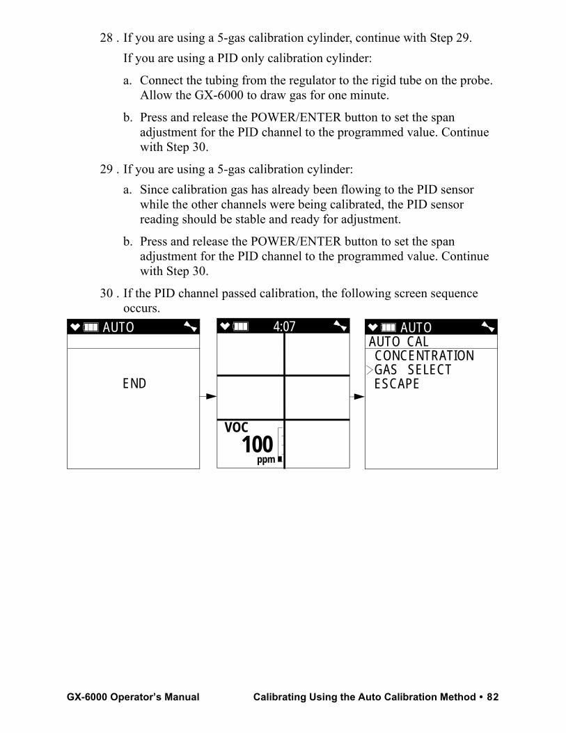
28 . If you are using a 5-gas calibration cylinder, continue with Step 29.If you are using a PID only calibration cylinder:
a. Connect the tubing from the regulator to the rigid tube on the probe. Allow the GX-6000 to draw gas for one minute.
b. Press and release the POWER/ENTER button to set the span adjustment for the PID channel to the programmed value. Continue with Step 30.
29 . If you are using a 5-gas calibration cylinder: a. Since calibration gas has already been flowing to the PID sensor
while the other channels were being calibrated, the PID sensor reading should be stable and ready for adjustment.
b. Press and release the POWER/ENTER button to set the span adjustment for the PID channel to the programmed value. Continue with Step 30.
30 . If the PID channel passed calibration, the following screen sequence occurs.
AUTO
END
4:07
VOC
ppm
100
AUTO AUTO CAL CONCENTRATION GAS SELECT ESCAPE
GX-6000 Operator’s Manual Calibrating Using the Auto Calibration Method • 82
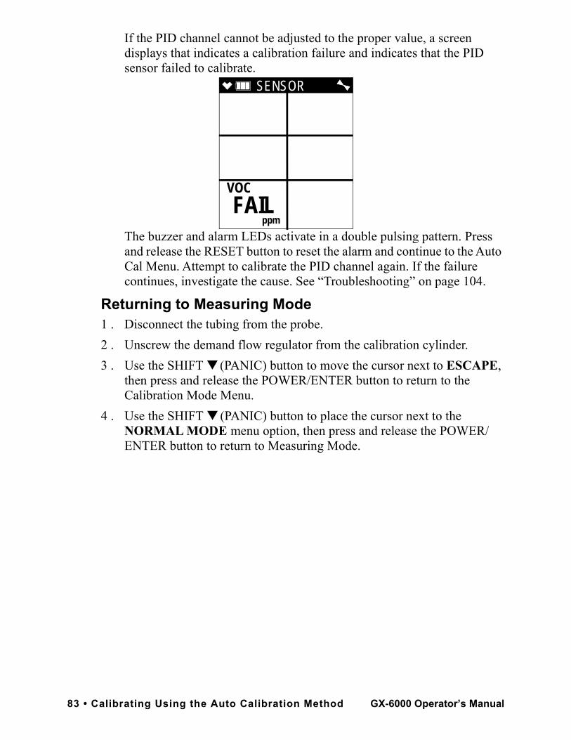
If the PID channel cannot be adjusted to the proper value, a screen displays that indicates a calibration failure and indicates that the PID sensor failed to calibrate.
The buzzer and alarm LEDs activate in a double pulsing pattern. Press and release the RESET button to reset the alarm and continue to the Auto Cal Menu. Attempt to calibrate the PID channel again. If the failure continues, investigate the cause. See “Troubleshooting” on page 104.
Returning to Measuring Mode1 . Disconnect the tubing from the probe.2 . Unscrew the demand flow regulator from the calibration cylinder.3 . Use the SHIFT ▼ (PANIC) button to move the cursor next to ESCAPE,
then press and release the POWER/ENTER button to return to the Calibration Mode Menu.
4 . Use the SHIFT ▼ (PANIC) button to place the cursor next to the NORMAL MODE menu option, then press and release the POWER/ENTER button to return to Measuring Mode.
SENSOR
VOC
ppm
FAIL
83 • Calibrating Using the Auto Calibration Method GX-6000 Operator’s Manual
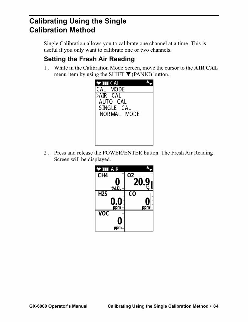
Calibrating Using the Single Calibration Method
Single Calibration allows you to calibrate one channel at a time. This is useful if you only want to calibrate one or two channels.Setting the Fresh Air Reading1 . While in the Calibration Mode Screen, move the cursor to the AIR CAL
menu item by using the SHIFT ▼ (PANIC) button.
2 . Press and release the POWER/ENTER button. The Fresh Air Reading Screen will be displayed.
CAL CAL MODE AIR CAL AUTO CAL SINGLE CAL NORMAL MODE
AIR CH4 O2
%LEL % H2S CO
ppm ppm
VOC
ppm
0 20.9
0.0 0
0
GX-6000 Operator’s Manual Calibrating Using the Single Calibration Method • 84
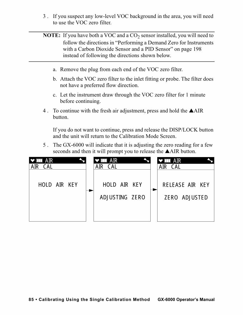
3 . If you suspect any low-level VOC background in the area, you will need to use the VOC zero filter.
NOTE: If you have both a VOC and a CO2 sensor installed, you will need to follow the directions in “Performing a Demand Zero for Instruments with a Carbon Dioxide Sensor and a PID Sensor” on page 198 instead of following the directions shown below.
a. Remove the plug from each end of the VOC zero filter.
b. Attach the VOC zero filter to the inlet fitting or probe. The filter does not have a preferred flow direction.
c. Let the instrument draw through the VOC zero filter for 1 minute before continuing.
4 . To continue with the fresh air adjustment, press and hold the ▲AIR button.
If you do not want to continue, press and release the DISP/LOCK button and the unit will return to the Calibration Mode Screen.
5 . The GX-6000 will indicate that it is adjusting the zero reading for a few seconds and then it will prompt you to release the ▲AIR button.
AIR AIR CAL
HOLD AIR KEY
AIR AIR CAL
HOLD AIR KEY
ADJUSTING ZERO
AIR AIR CAL
RELEASE AIR KEY
ZERO ADJUSTED
85 • Calibrating Using the Single Calibration Method GX-6000 Operator’s Manual
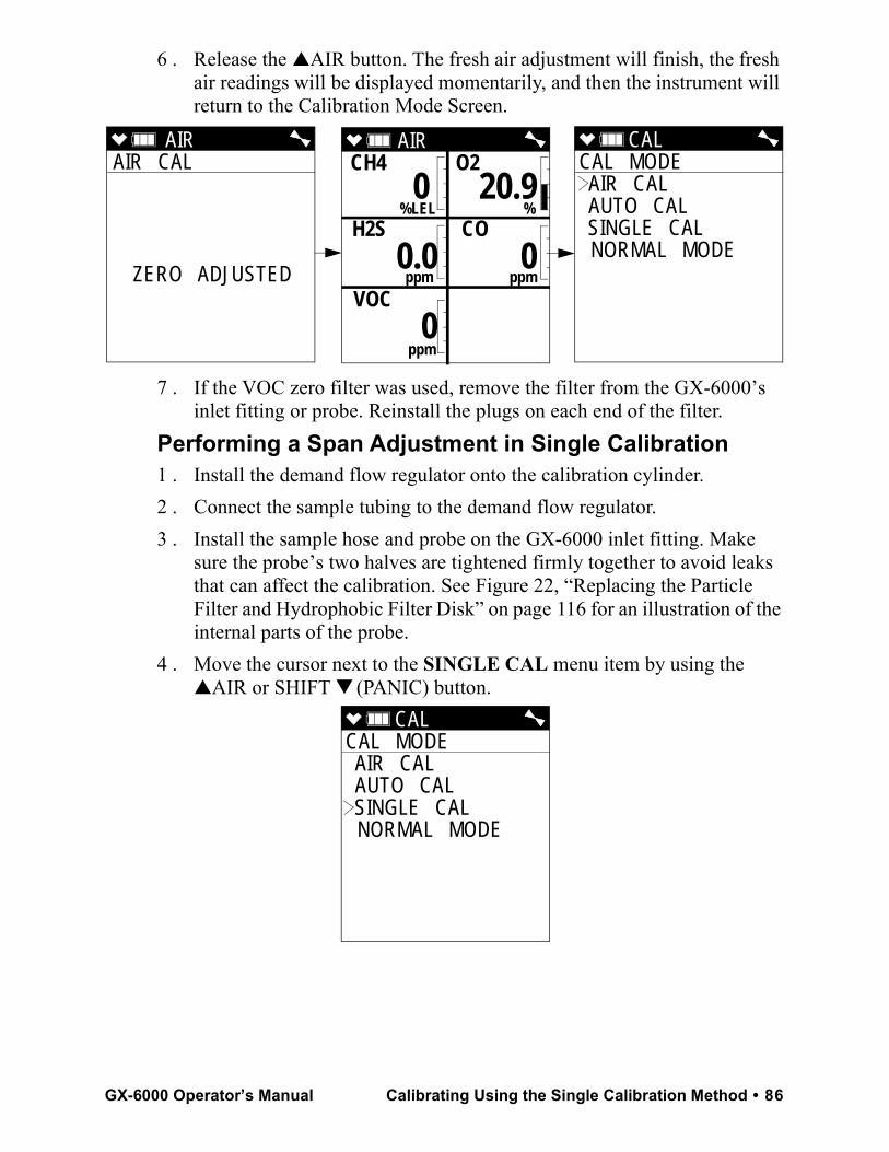
6 . Release the ▲AIR button. The fresh air adjustment will finish, the fresh air readings will be displayed momentarily, and then the instrument will return to the Calibration Mode Screen.
7 . If the VOC zero filter was used, remove the filter from the GX-6000’s inlet fitting or probe. Reinstall the plugs on each end of the filter.
Performing a Span Adjustment in Single Calibration1 . Install the demand flow regulator onto the calibration cylinder.2 . Connect the sample tubing to the demand flow regulator.3 . Install the sample hose and probe on the GX-6000 inlet fitting. Make
sure the probe’s two halves are tightened firmly together to avoid leaks that can affect the calibration. See Figure 22, “Replacing the Particle Filter and Hydrophobic Filter Disk” on page 116 for an illustration of the internal parts of the probe.
4 . Move the cursor next to the SINGLE CAL menu item by using the ▲AIR or SHIFT ▼ (PANIC) button.
AIR AIR CAL
ZERO ADJUSTED
AIR CH4 O2
%LEL % H2S CO
ppm ppm
VOC
ppm
0 20.9
0.0 0
0
CAL CAL MODE AIR CAL AUTO CAL SINGLE CAL NORMAL MODE
CAL CAL MODE AIR CAL AUTO CAL SINGLE CAL NORMAL MODE
GX-6000 Operator’s Manual Calibrating Using the Single Calibration Method • 86
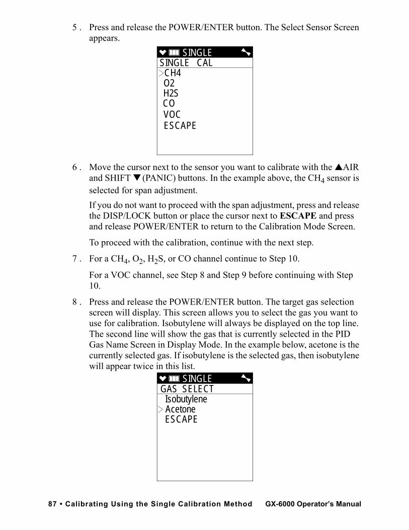
5 . Press and release the POWER/ENTER button. The Select Sensor Screen appears.
6 . Move the cursor next to the sensor you want to calibrate with the ▲AIR and SHIFT ▼ (PANIC) buttons. In the example above, the CH4 sensor is selected for span adjustment.If you do not want to proceed with the span adjustment, press and release the DISP/LOCK button or place the cursor next to ESCAPE and press and release POWER/ENTER to return to the Calibration Mode Screen.
To proceed with the calibration, continue with the next step.
7 . For a CH4, O2, H2S, or CO channel continue to Step 10.
For a VOC channel, see Step 8 and Step 9 before continuing with Step 10.
8 . Press and release the POWER/ENTER button. The target gas selection screen will display. This screen allows you to select the gas you want to use for calibration. Isobutylene will always be displayed on the top line. The second line will show the gas that is currently selected in the PID Gas Name Screen in Display Mode. In the example below, acetone is the currently selected gas. If isobutylene is the selected gas, then isobutylene will appear twice in this list.
SINGLE SINGLE CAL CH4 O2 H2S CO VOC ESCAPE
SINGLE GAS SELECT
Isobutylene Acetone
ESCAPE
87 • Calibrating Using the Single Calibration Method GX-6000 Operator’s Manual
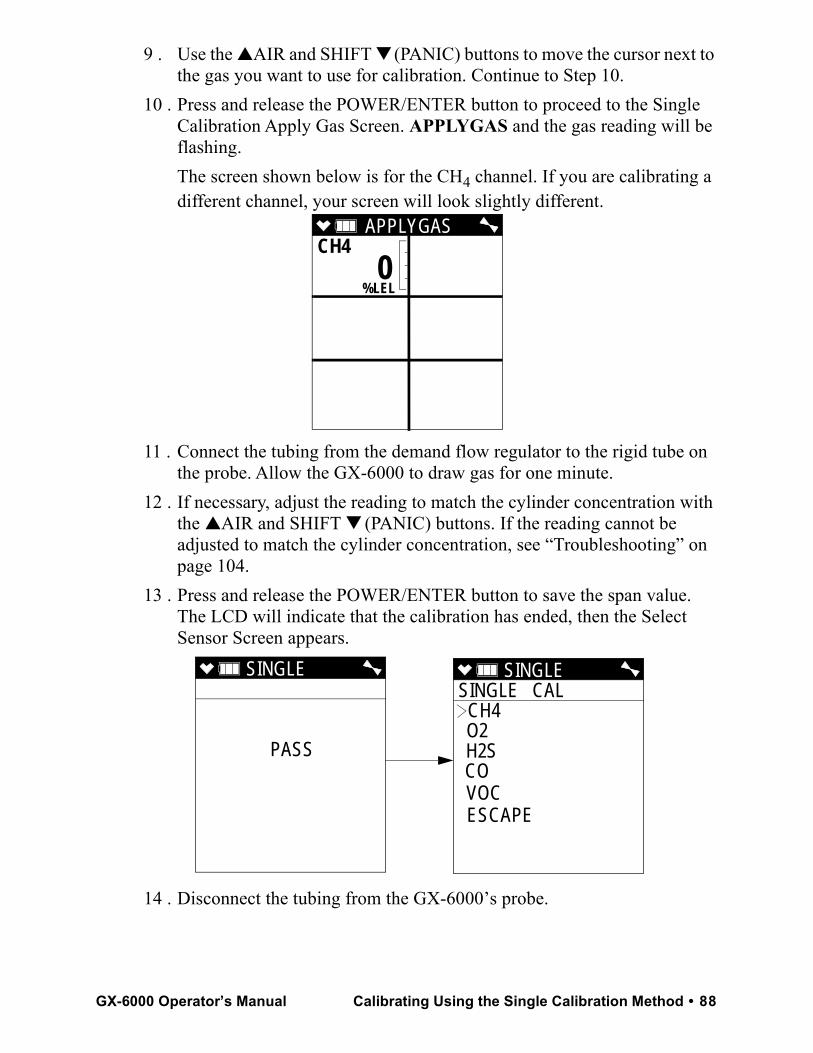
9 . Use the ▲AIR and SHIFT ▼ (PANIC) buttons to move the cursor next to the gas you want to use for calibration. Continue to Step 10.
10 . Press and release the POWER/ENTER button to proceed to the Single Calibration Apply Gas Screen. APPLYGAS and the gas reading will be flashing. The screen shown below is for the CH4 channel. If you are calibrating a different channel, your screen will look slightly different.
11 . Connect the tubing from the demand flow regulator to the rigid tube on the probe. Allow the GX-6000 to draw gas for one minute.
12 . If necessary, adjust the reading to match the cylinder concentration with the ▲AIR and SHIFT ▼ (PANIC) buttons. If the reading cannot be adjusted to match the cylinder concentration, see “Troubleshooting” on page 104.
13 . Press and release the POWER/ENTER button to save the span value. The LCD will indicate that the calibration has ended, then the Select Sensor Screen appears.
14 . Disconnect the tubing from the GX-6000’s probe.
APPLYGASCH4
%LEL
0
SINGLE
PASS
SINGLE SINGLE CAL CH4 O2 H2S CO VOC ESCAPE
GX-6000 Operator’s Manual Calibrating Using the Single Calibration Method • 88
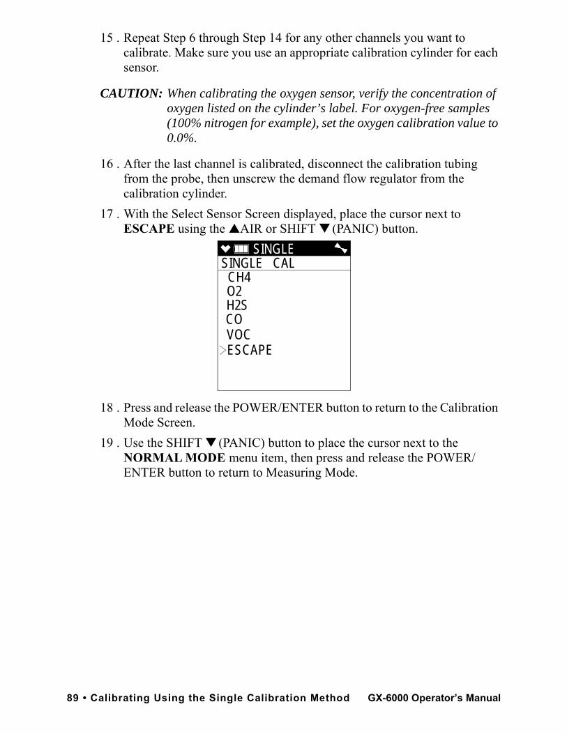
15 . Repeat Step 6 through Step 14 for any other channels you want to calibrate. Make sure you use an appropriate calibration cylinder for each sensor.
CAUTION: When calibrating the oxygen sensor, verify the concentration of oxygen listed on the cylinder’s label. For oxygen-free samples (100% nitrogen for example), set the oxygen calibration value to 0.0%.
16 . After the last channel is calibrated, disconnect the calibration tubing from the probe, then unscrew the demand flow regulator from the calibration cylinder.
17 . With the Select Sensor Screen displayed, place the cursor next to ESCAPE using the ▲AIR or SHIFT ▼ (PANIC) button.
18 . Press and release the POWER/ENTER button to return to the Calibration Mode Screen.
19 . Use the SHIFT ▼ (PANIC) button to place the cursor next to the NORMAL MODE menu item, then press and release the POWER/ENTER button to return to Measuring Mode.
SINGLE SINGLE CAL CH4 O2 H2S CO VOC ESCAPE
89 • Calibrating Using the Single Calibration Method GX-6000 Operator’s Manual
Performing a Bump Test
NOTE: The BUMP DISP menu item in Maintenance Mode is factory set to OFF. The BUMP TEST menu item will not appear unless BUMP DISP is set to ON. See “Updating the Bump Display Setting” on page 152 for instructions.
NOTE: The GX-6000 uses parameters defined in the BUMP PARAMETERS menu item of Maintenance Mode while performing a bump test. To view or update these parameters, see “Updating the Bump Parameters” on page 152.
If the combustible gas channel is calibrated to a gas other than methane, use an appropriate multigas cylinder.1 . Install the demand flow regulator onto the calibration cylinder.2 . Connect the sample tubing to the demand flow regulator.3 . Install the sample hose and probe on the GX-6000 inlet fitting. Make
sure the probe’s two halves are tightened firmly together to avoid leaks that can affect the calibration. See Figure 22, “Replacing the Particle Filter and Hydrophobic Filter Disk” on page 116 for an illustration of the internal parts of the probe.
4 . While in Measuring Mode, press and hold the SHIFT ▼ (PANIC) button, then press the DISP/LOCK button and release both buttons.
5 . If the unit prompts you for the password, enter it by using the ▲AIR and SHIFT ▼ (PANIC) buttons to select each password number and then pressing and releasing POWER/ENTER to enter the number and move on to the next one.
NOTE: You will only be prompted to enter a password if the PASSWORD menu item in User Mode is set to ON. See “Turning the Password Function On or Off” on page 102 for instructions to update the PASSWORD setting and to choose a password.
GX-6000 Operator’s Manual Performing a Bump Test • 90
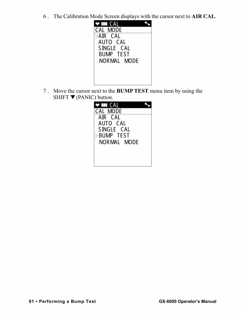
6 . The Calibration Mode Screen displays with the cursor next to AIR CAL.
7 . Move the cursor next to the BUMP TEST menu item by using the SHIFT ▼ (PANIC) button.
CAL CAL MODE
AIR CAL AUTO CAL SINGLE CAL BUMP TEST NORMAL MODE
CAL CAL MODE
AIR CAL AUTO CAL SINGLE CAL BUMP TEST NORMAL MODE
91 • Performing a Bump Test GX-6000 Operator’s Manual
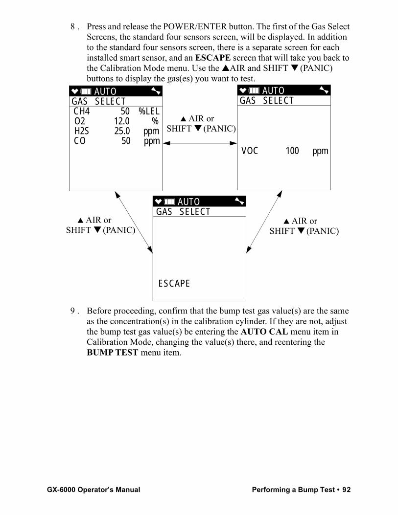
8 . Press and release the POWER/ENTER button. The first of the Gas Select Screens, the standard four sensors screen, will be displayed. In addition to the standard four sensors screen, there is a separate screen for each installed smart sensor, and an ESCAPE screen that will take you back to the Calibration Mode menu. Use the ▲AIR and SHIFT ▼ (PANIC) buttons to display the gas(es) you want to test.
9 . Before proceeding, confirm that the bump test gas value(s) are the same as the concentration(s) in the calibration cylinder. If they are not, adjust the bump test gas value(s) be entering the AUTO CAL menu item in Calibration Mode, changing the value(s) there, and reentering the BUMP TEST menu item.
AUTO GAS SELECT CH4 50 %LELO2 12.0 %H2S 25.0 ppmCO 50 ppm
AUTO GAS SELECT
VOC 100 ppm
AUTO GAS SELECT
ESCAPE
▲ AIR orSHIFT ▼ (PANIC)
▲ AIR orSHIFT ▼ (PANIC)
▲ AIR orSHIFT ▼ (PANIC)
GX-6000 Operator’s Manual Performing a Bump Test • 92
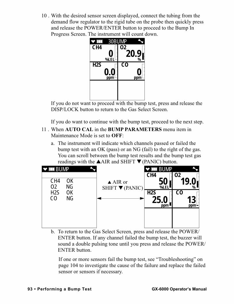
10 . With the desired sensor screen displayed, connect the tubing from the demand flow regulator to the rigid tube on the probe then quickly press and release the POWER/ENTER button to proceed to the Bump In Progress Screen. The instrument will count down.
If you do not want to proceed with the bump test, press and release the DISP/LOCK button to return to the Gas Select Screen.
If you do want to continue with the bump test, proceed to the next step.11 . When AUTO CAL in the BUMP PARAMETERS menu item in
Maintenance Mode is set to OFF: a. The instrument will indicate which channels passed or failed the
bump test with an OK (pass) or an NG (fail) to the right of the gas. You can scroll between the bump test results and the bump test gas readings with the ▲AIR and SHIFT ▼ (PANIC) button.
b. To return to the Gas Select Screen, press and release the POWER/ENTER button. If any channel failed the bump test, the buzzer will sound a double pulsing tone until you press and release the POWER/ENTER button.
If one or more sensors fail the bump test, see “Troubleshooting” on page 104 to investigate the cause of the failure and replace the failed sensor or sensors if necessary.
30BUMPCH4 O2
%LEL % H2S CO
ppm ppm
0 20.9
0.0 0
BUMP
CH4 OK O2 NG H2S OK CO NG
BUMP CH4 O2
%LEL % H2S CO
ppm ppm
50 19.0
25.0 13
▲ AIR orSHIFT ▼ (PANIC)
93 • Performing a Bump Test GX-6000 Operator’s Manual
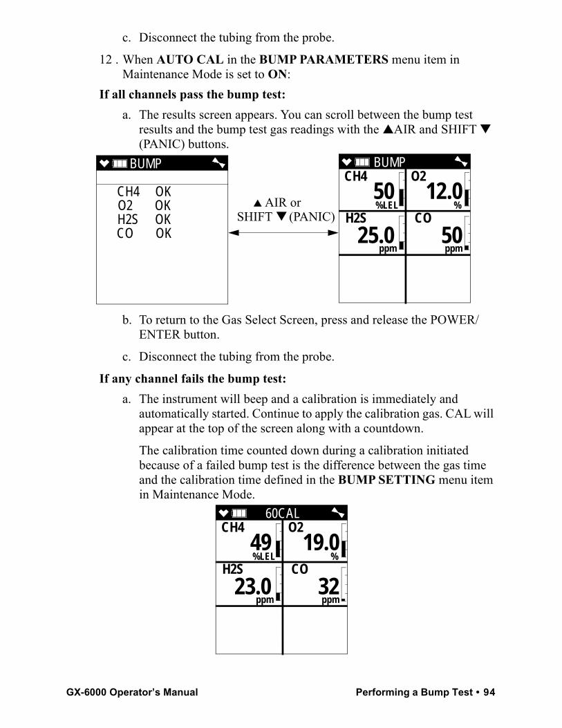
c. Disconnect the tubing from the probe.
12 . When AUTO CAL in the BUMP PARAMETERS menu item in Maintenance Mode is set to ON:
If all channels pass the bump test: a. The results screen appears. You can scroll between the bump test
results and the bump test gas readings with the ▲AIR and SHIFT ▼ (PANIC) buttons.
b. To return to the Gas Select Screen, press and release the POWER/ENTER button.
c. Disconnect the tubing from the probe.
If any channel fails the bump test: a. The instrument will beep and a calibration is immediately and
automatically started. Continue to apply the calibration gas. CAL will appear at the top of the screen along with a countdown.
The calibration time counted down during a calibration initiated because of a failed bump test is the difference between the gas time and the calibration time defined in the BUMP SETTING menu item in Maintenance Mode.
BUMP
CH4 OK O2 OK H2S OK CO OK
BUMP CH4 O2
%LEL % H2S CO
ppm ppm
50 12.0
25.0 50
▲ AIR or SHIFT ▼ (PANIC)
60CALCH4 O2
%LEL % H2S CO
ppm ppm
49 19.0
23.0 32
GX-6000 Operator’s Manual Performing a Bump Test • 94
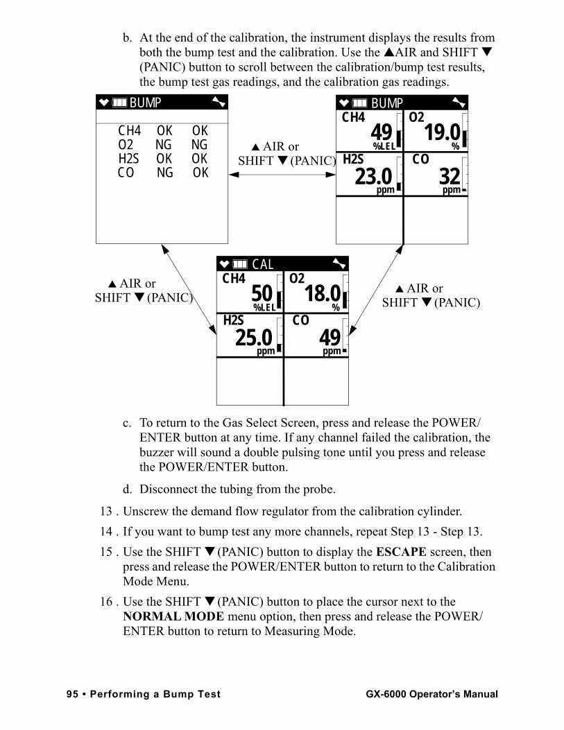
b. At the end of the calibration, the instrument displays the results from both the bump test and the calibration. Use the ▲AIR and SHIFT ▼ (PANIC) button to scroll between the calibration/bump test results, the bump test gas readings, and the calibration gas readings.
c. To return to the Gas Select Screen, press and release the POWER/ENTER button at any time. If any channel failed the calibration, the buzzer will sound a double pulsing tone until you press and release the POWER/ENTER button.
d. Disconnect the tubing from the probe.
13 . Unscrew the demand flow regulator from the calibration cylinder.14 . If you want to bump test any more channels, repeat Step 13 - Step 13.15 . Use the SHIFT ▼ (PANIC) button to display the ESCAPE screen, then
press and release the POWER/ENTER button to return to the Calibration Mode Menu.
16 . Use the SHIFT ▼ (PANIC) button to place the cursor next to the NORMAL MODE menu option, then press and release the POWER/ENTER button to return to Measuring Mode.
BUMP
CH4 OK OKO2 NG NGH2S OK OKCO NG OK
CAL CH4 O2
%LEL % H2S CO
ppm ppm
50 18.0
25.0 49
BUMP CH4 O2
%LEL % H2S CO
ppm ppm
49 19.0
23.0 32
▲ AIR or
▲ AIR or ▲ AIR or
SHIFT ▼ (PANIC)
SHIFT ▼ (PANIC) SHIFT ▼ (PANIC)
95 • Performing a Bump Test GX-6000 Operator’s Manual
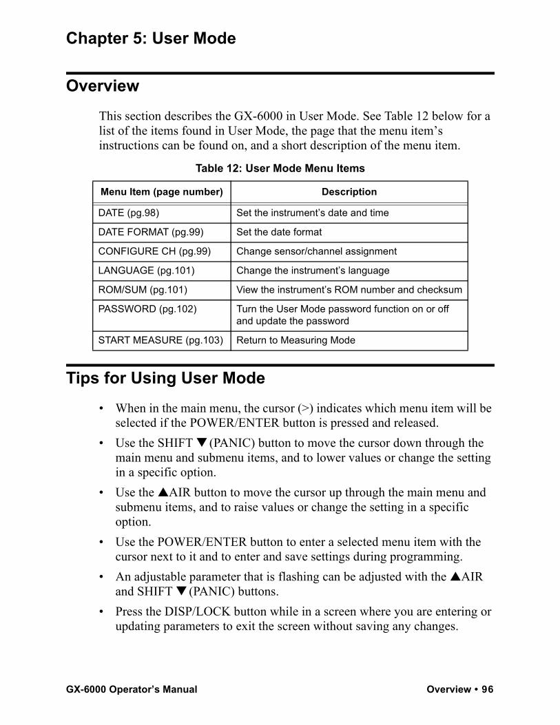
Chapter 5: User Mode
OverviewThis section describes the GX-6000 in User Mode. See Table 12 below for a list of the items found in User Mode, the page that the menu item’s instructions can be found on, and a short description of the menu item.
Tips for Using User Mode• When in the main menu, the cursor (>) indicates which menu item will be
selected if the POWER/ENTER button is pressed and released.• Use the SHIFT ▼ (PANIC) button to move the cursor down through the
main menu and submenu items, and to lower values or change the setting in a specific option.
• Use the ▲AIR button to move the cursor up through the main menu and submenu items, and to raise values or change the setting in a specific option.
• Use the POWER/ENTER button to enter a selected menu item with the cursor next to it and to enter and save settings during programming.
• An adjustable parameter that is flashing can be adjusted with the ▲AIR and SHIFT ▼ (PANIC) buttons.
• Press the DISP/LOCK button while in a screen where you are entering or updating parameters to exit the screen without saving any changes.
Table 12: User Mode Menu Items
Menu Item (page number) Description
DATE (pg.98) Set the instrument’s date and time
DATE FORMAT (pg.99) Set the date format
CONFIGURE CH (pg.99) Change sensor/channel assignment
LANGUAGE (pg.101) Change the instrument’s language
ROM/SUM (pg.101) View the instrument’s ROM number and checksum
PASSWORD (pg.102) Turn the User Mode password function on or off and update the password
START MEASURE (pg.103) Return to Measuring Mode
GX-6000 Operator’s Manual Overview • 96
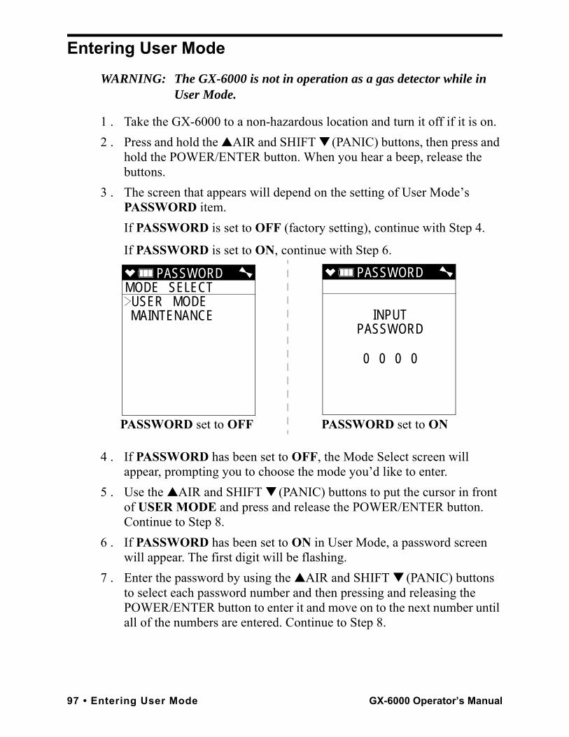
Entering User ModeWARNING: The GX-6000 is not in operation as a gas detector while in
User Mode.
1 . Take the GX-6000 to a non-hazardous location and turn it off if it is on.2 . Press and hold the ▲AIR and SHIFT ▼ (PANIC) buttons, then press and
hold the POWER/ENTER button. When you hear a beep, release the buttons.
3 . The screen that appears will depend on the setting of User Mode’s PASSWORD item. If PASSWORD is set to OFF (factory setting), continue with Step 4.
If PASSWORD is set to ON, continue with Step 6.
4 . If PASSWORD has been set to OFF, the Mode Select screen will appear, prompting you to choose the mode you’d like to enter.
5 . Use the ▲AIR and SHIFT ▼ (PANIC) buttons to put the cursor in front of USER MODE and press and release the POWER/ENTER button. Continue to Step 8.
6 . If PASSWORD has been set to ON in User Mode, a password screen will appear. The first digit will be flashing.
7 . Enter the password by using the ▲AIR and SHIFT ▼ (PANIC) buttons to select each password number and then pressing and releasing the POWER/ENTER button to enter it and move on to the next number until all of the numbers are entered. Continue to Step 8.
PASSWORDMODE SELECT USER MODE MAINTENANCE
PASSWORD
INPUTPASSWORD
0 0 0 0
PASSWORD set to OFF PASSWORD set to ON
97 • Entering User Mode GX-6000 Operator’s Manual
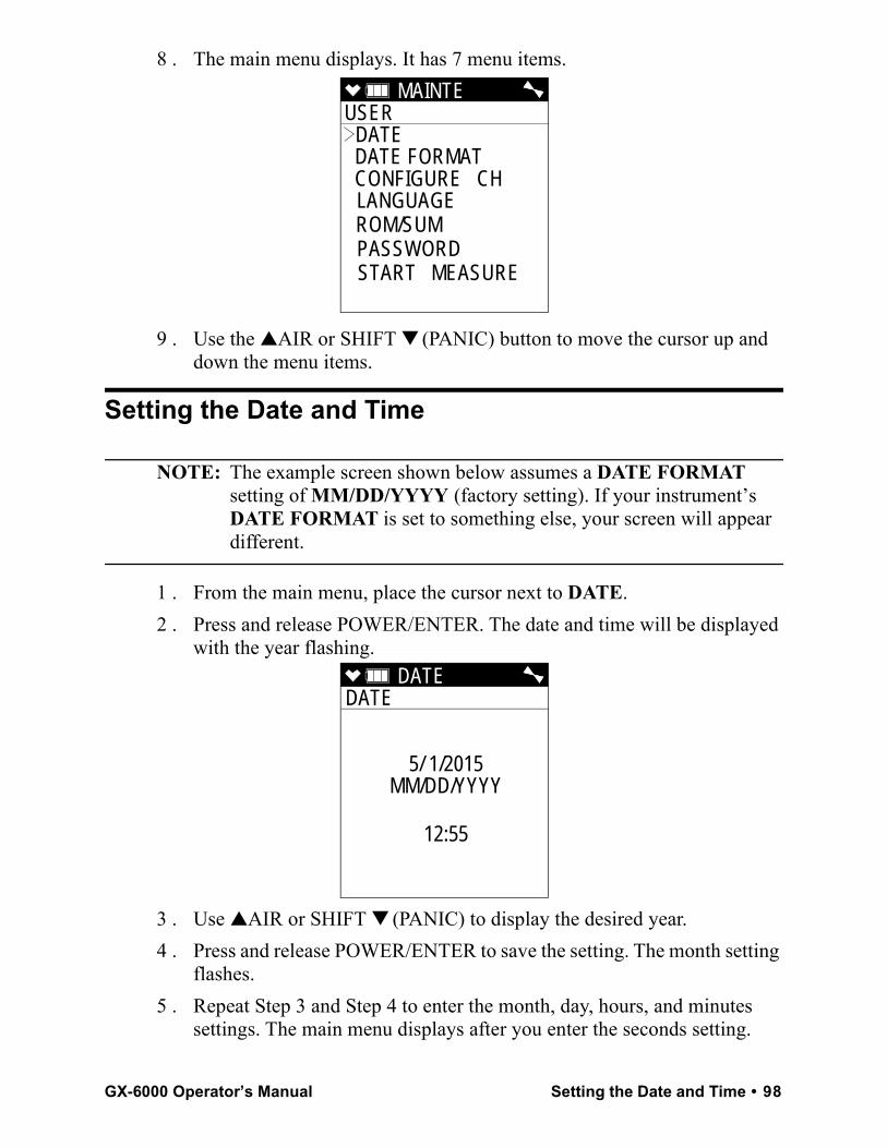
8 . The main menu displays. It has 7 menu items.
9 . Use the ▲AIR or SHIFT ▼ (PANIC) button to move the cursor up and down the menu items.
Setting the Date and Time
NOTE: The example screen shown below assumes a DATE FORMAT setting of MM/DD/YYYY (factory setting). If your instrument’s DATE FORMAT is set to something else, your screen will appear different.
1 . From the main menu, place the cursor next to DATE.2 . Press and release POWER/ENTER. The date and time will be displayed
with the year flashing.
3 . Use ▲AIR or SHIFT ▼ (PANIC) to display the desired year.4 . Press and release POWER/ENTER to save the setting. The month setting
flashes.5 . Repeat Step 3 and Step 4 to enter the month, day, hours, and minutes
settings. The main menu displays after you enter the seconds setting.
MAINTE USER
DATE DATE FORMAT CONFIGURE CH LANGUAGE ROM/SUM PASSWORD START MEASURE
DATE DATE
5/ 1/2015MM/DD/YYYY
12:55
GX-6000 Operator’s Manual Setting the Date and Time • 98
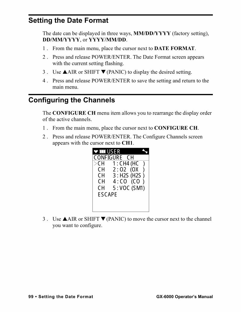
Setting the Date FormatThe date can be displayed in three ways, MM/DD/YYYY (factory setting), DD/MM/YYYY, or YYYY/MM/DD.1 . From the main menu, place the cursor next to DATE FORMAT.2 . Press and release POWER/ENTER. The Date Format screen appears
with the current setting flashing.3 . Use ▲AIR or SHIFT ▼ (PANIC) to display the desired setting.4 . Press and release POWER/ENTER to save the setting and return to the
main menu.
Configuring the ChannelsThe CONFIGURE CH menu item allows you to rearrange the display order of the active channels. 1 . From the main menu, place the cursor next to CONFIGURE CH.2 . Press and release POWER/ENTER. The Configure Channels screen
appears with the cursor next to CH1.
3 . Use ▲AIR or SHIFT ▼ (PANIC) to move the cursor next to the channel you want to configure.
USER CONFIGURE CH
CH 1 : CH4 (HC )CH 2 : O2 (OX ) CH 3 : H2S (H2S ) CH 4 : CO (CO )CH 5 : VOC (SM1)ESCAPE
99 • Setting the Date Format GX-6000 Operator’s Manual
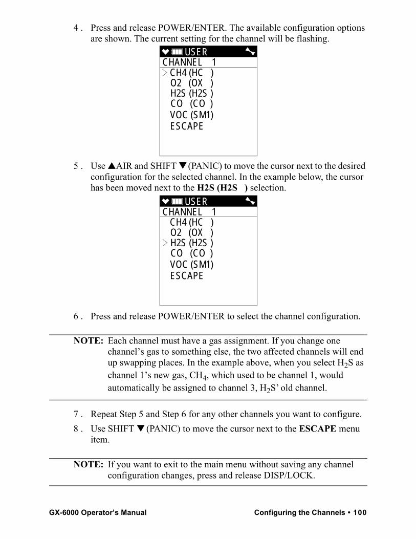
4 . Press and release POWER/ENTER. The available configuration options are shown. The current setting for the channel will be flashing.
5 . Use ▲AIR and SHIFT ▼ (PANIC) to move the cursor next to the desired configuration for the selected channel. In the example below, the cursor has been moved next to the H2S (H2S ) selection.
6 . Press and release POWER/ENTER to select the channel configuration.
NOTE: Each channel must have a gas assignment. If you change one channel’s gas to something else, the two affected channels will end up swapping places. In the example above, when you select H2S as channel 1’s new gas, CH4, which used to be channel 1, would automatically be assigned to channel 3, H2S’ old channel.
7 . Repeat Step 5 and Step 6 for any other channels you want to configure.8 . Use SHIFT ▼ (PANIC) to move the cursor next to the ESCAPE menu
item.
NOTE: If you want to exit to the main menu without saving any channel configuration changes, press and release DISP/LOCK.
USER CHANNEL 1
CH4 (HC ) O2 (OX ) H2S (H2S ) CO (CO ) VOC (SM1) ESCAPE
USER CHANNEL 1
CH4 (HC ) O2 (OX ) H2S (H2S ) CO (CO ) VOC (SM1) ESCAPE
GX-6000 Operator’s Manual Configuring the Channels • 100
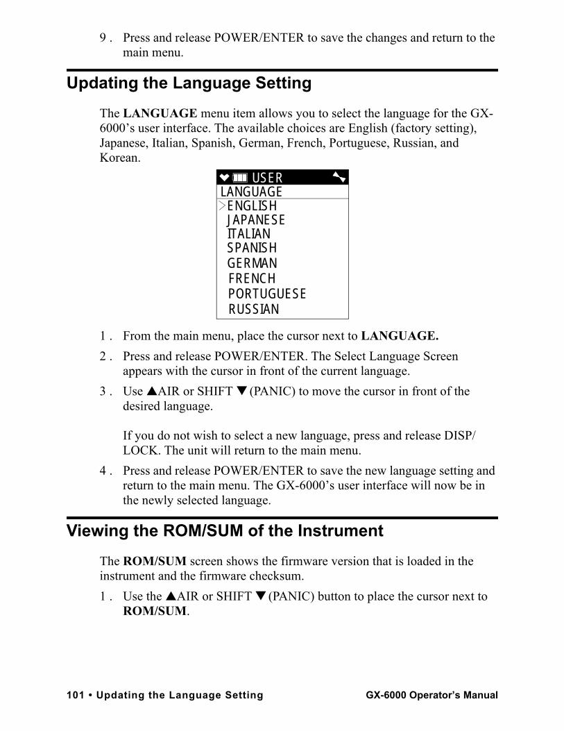
9 . Press and release POWER/ENTER to save the changes and return to the main menu.
Updating the Language SettingThe LANGUAGE menu item allows you to select the language for the GX-6000’s user interface. The available choices are English (factory setting), Japanese, Italian, Spanish, German, French, Portuguese, Russian, and Korean.
1 . From the main menu, place the cursor next to LANGUAGE.2 . Press and release POWER/ENTER. The Select Language Screen
appears with the cursor in front of the current language. 3 . Use ▲AIR or SHIFT ▼ (PANIC) to move the cursor in front of the
desired language.
If you do not wish to select a new language, press and release DISP/LOCK. The unit will return to the main menu.
4 . Press and release POWER/ENTER to save the new language setting and return to the main menu. The GX-6000’s user interface will now be in the newly selected language.
Viewing the ROM/SUM of the InstrumentThe ROM/SUM screen shows the firmware version that is loaded in the instrument and the firmware checksum. 1 . Use the ▲AIR or SHIFT ▼ (PANIC) button to place the cursor next to
ROM/SUM.
USER LANGUAGE
ENGLISH JAPANESE ITALIAN SPANISH GERMAN FRENCH PORTUGUESE RUSSIAN
101 • Updating the Language Setting GX-6000 Operator’s Manual
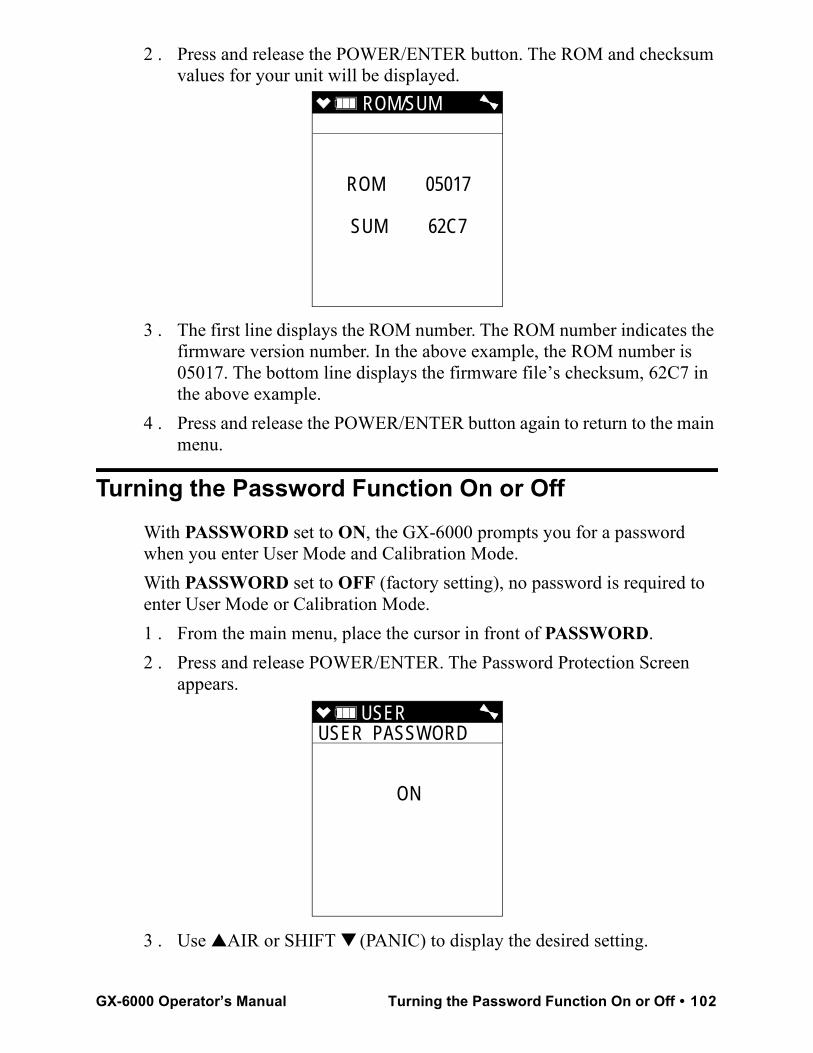
2 . Press and release the POWER/ENTER button. The ROM and checksum values for your unit will be displayed.
3 . The first line displays the ROM number. The ROM number indicates the firmware version number. In the above example, the ROM number is 05017. The bottom line displays the firmware file’s checksum, 62C7 in the above example.
4 . Press and release the POWER/ENTER button again to return to the main menu.
Turning the Password Function On or OffWith PASSWORD set to ON, the GX-6000 prompts you for a password when you enter User Mode and Calibration Mode.With PASSWORD set to OFF (factory setting), no password is required to enter User Mode or Calibration Mode.1 . From the main menu, place the cursor in front of PASSWORD.2 . Press and release POWER/ENTER. The Password Protection Screen
appears.
3 . Use ▲AIR or SHIFT ▼ (PANIC) to display the desired setting.
ROM/SUM
ROM 05017
SUM 62C7
USER USER PASSWORD
ON
GX-6000 Operator’s Manual Turning the Password Function On or Off • 102
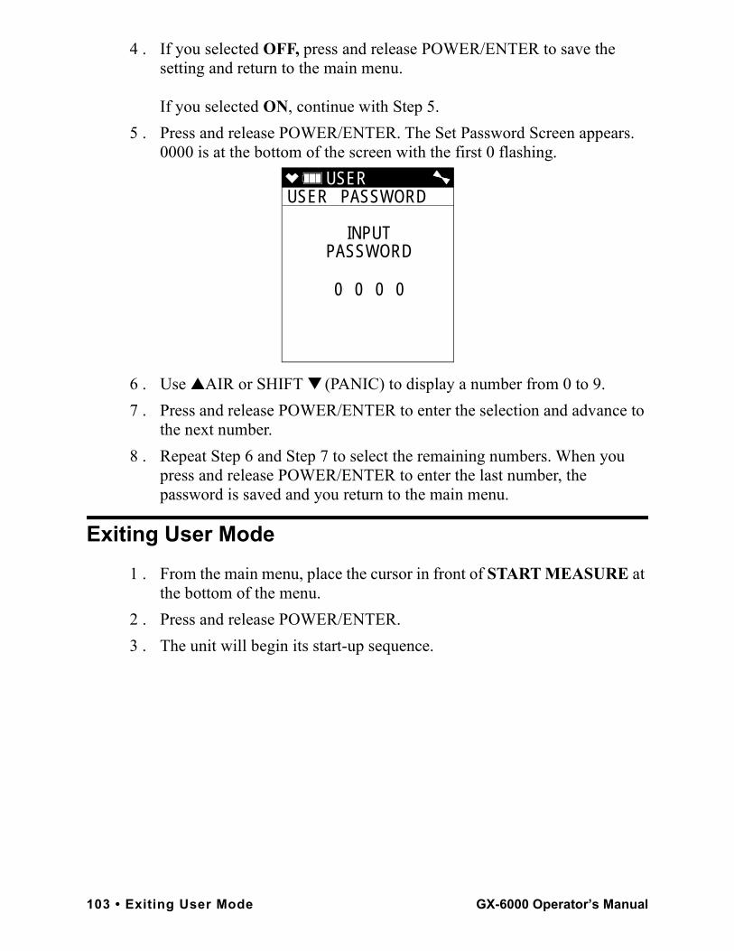
4 . If you selected OFF, press and release POWER/ENTER to save the setting and return to the main menu.
If you selected ON, continue with Step 5.5 . Press and release POWER/ENTER. The Set Password Screen appears.
0000 is at the bottom of the screen with the first 0 flashing.
6 . Use ▲AIR or SHIFT ▼ (PANIC) to display a number from 0 to 9.7 . Press and release POWER/ENTER to enter the selection and advance to
the next number.8 . Repeat Step 6 and Step 7 to select the remaining numbers. When you
press and release POWER/ENTER to enter the last number, the password is saved and you return to the main menu.
Exiting User Mode1 . From the main menu, place the cursor in front of START MEASURE at
the bottom of the menu.2 . Press and release POWER/ENTER.3 . The unit will begin its start-up sequence.
USER USER PASSWORD
INPUTPASSWORD
0 0 0 0
103 • Exiting User Mode GX-6000 Operator’s Manual
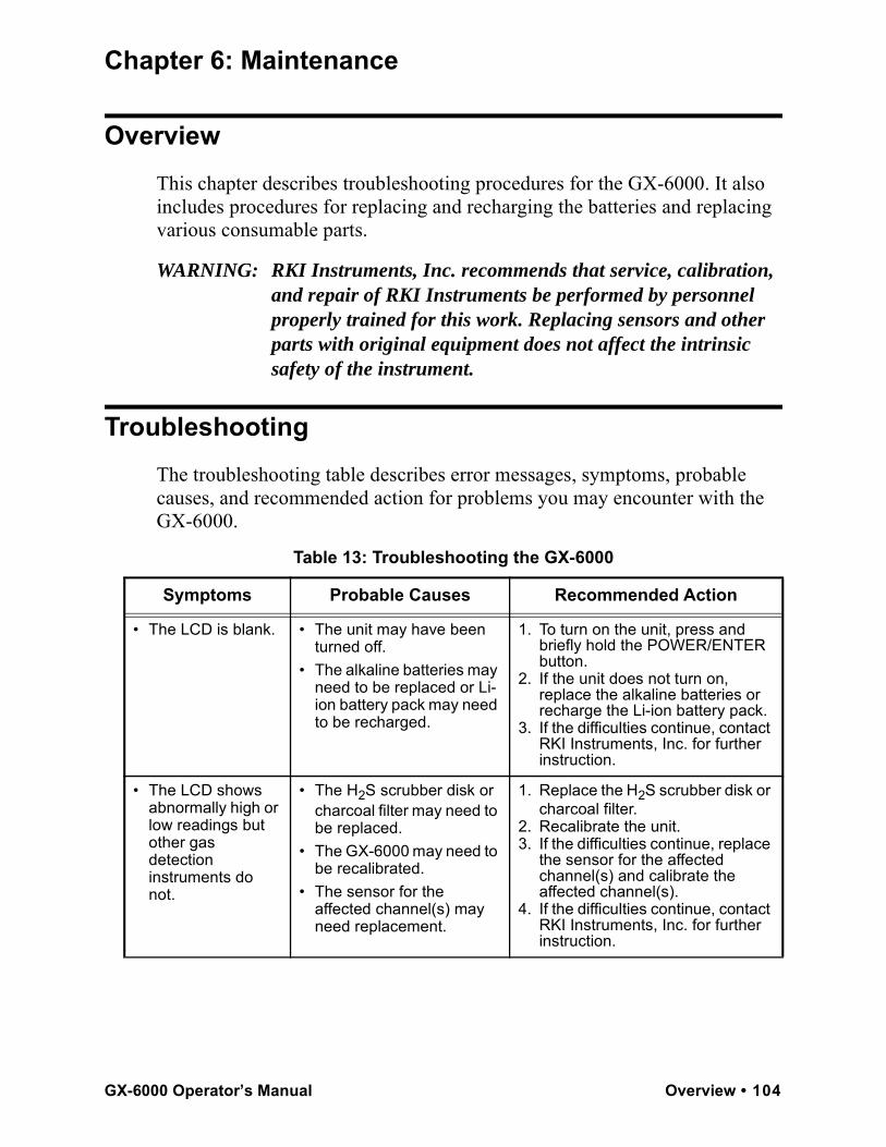
Chapter 6: Maintenance
OverviewThis chapter describes troubleshooting procedures for the GX-6000. It also includes procedures for replacing and recharging the batteries and replacing various consumable parts.
WARNING: RKI Instruments, Inc. recommends that service, calibration, and repair of RKI Instruments be performed by personnel properly trained for this work. Replacing sensors and other parts with original equipment does not affect the intrinsic safety of the instrument.
TroubleshootingThe troubleshooting table describes error messages, symptoms, probable causes, and recommended action for problems you may encounter with the GX-6000.
Table 13: Troubleshooting the GX-6000
Symptoms Probable Causes Recommended Action
• The LCD is blank. • The unit may have been turned off.
• The alkaline batteries may need to be replaced or Li-ion battery pack may need to be recharged.
1. To turn on the unit, press and briefly hold the POWER/ENTER button.
2. If the unit does not turn on, replace the alkaline batteries or recharge the Li-ion battery pack.
3. If the difficulties continue, contact RKI Instruments, Inc. for further instruction.
• The LCD shows abnormally high or low readings but other gas detection instruments do not.
• The H2S scrubber disk or charcoal filter may need to be replaced.
• The GX-6000 may need to be recalibrated.
• The sensor for the affected channel(s) may need replacement.
1. Replace the H2S scrubber disk or charcoal filter.
2. Recalibrate the unit.3. If the difficulties continue, replace
the sensor for the affected channel(s) and calibrate the affected channel(s).
4. If the difficulties continue, contact RKI Instruments, Inc. for further instruction.
GX-6000 Operator’s Manual Overview • 104
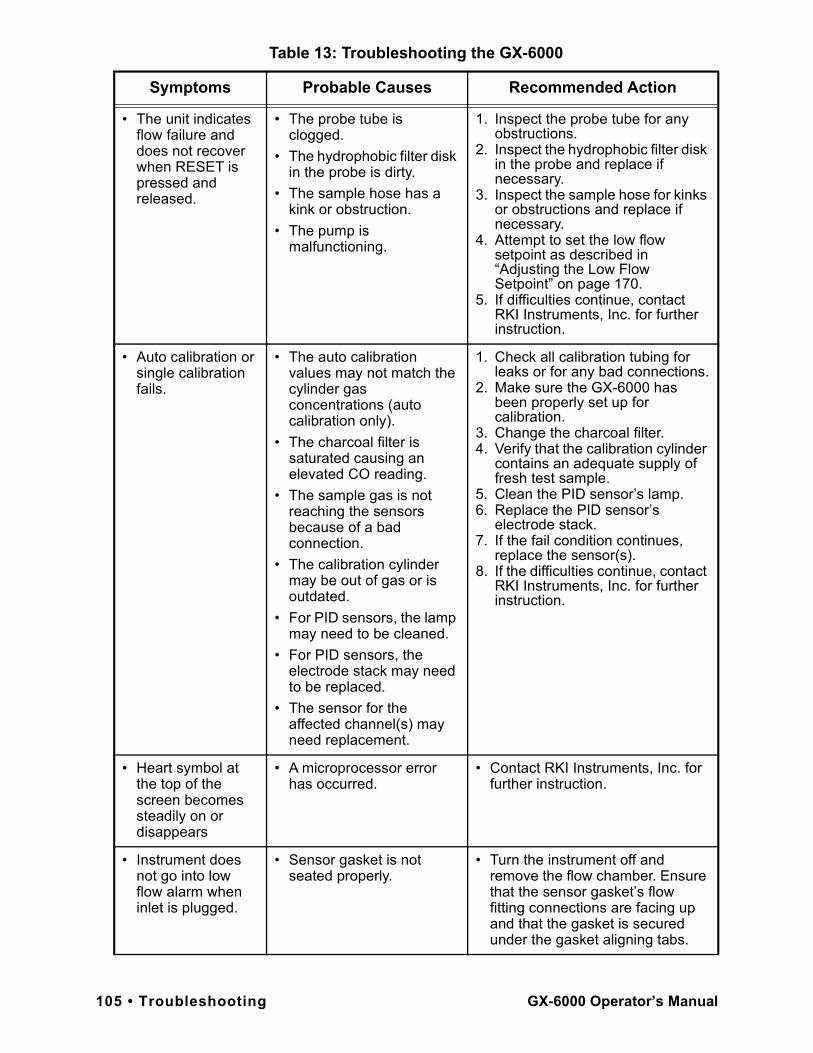
• The unit indicates flow failure and does not recover when RESET is pressed and released.
• The probe tube is clogged.
• The hydrophobic filter disk in the probe is dirty.
• The sample hose has a kink or obstruction.
• The pump is malfunctioning.
1. Inspect the probe tube for any obstructions.
2. Inspect the hydrophobic filter disk in the probe and replace if necessary.
3. Inspect the sample hose for kinks or obstructions and replace if necessary.
4. Attempt to set the low flow setpoint as described in “Adjusting the Low Flow Setpoint” on page 170.
5. If difficulties continue, contact RKI Instruments, Inc. for further instruction.
• Auto calibration or single calibration fails.
• The auto calibration values may not match the cylinder gas concentrations (auto calibration only).
• The charcoal filter is saturated causing an elevated CO reading.
• The sample gas is not reaching the sensors because of a bad connection.
• The calibration cylinder may be out of gas or is outdated.
• For PID sensors, the lamp may need to be cleaned.
• For PID sensors, the electrode stack may need to be replaced.
• The sensor for the affected channel(s) may need replacement.
1. Check all calibration tubing for leaks or for any bad connections.
2. Make sure the GX-6000 has been properly set up for calibration.
3. Change the charcoal filter.4. Verify that the calibration cylinder
contains an adequate supply of fresh test sample.
5. Clean the PID sensor’s lamp.6. Replace the PID sensor’s
electrode stack.7. If the fail condition continues,
replace the sensor(s).8. If the difficulties continue, contact
RKI Instruments, Inc. for further instruction.
• Heart symbol at the top of the screen becomes steadily on or disappears
• A microprocessor error has occurred.
• Contact RKI Instruments, Inc. for further instruction.
• Instrument does not go into low flow alarm when inlet is plugged.
• Sensor gasket is not seated properly.
• Turn the instrument off and remove the flow chamber. Ensure that the sensor gasket’s flow fitting connections are facing up and that the gasket is secured under the gasket aligning tabs.
Table 13: Troubleshooting the GX-6000
Symptoms Probable Causes Recommended Action
105 • Troubleshooting GX-6000 Operator’s Manual
Replacing or Recharging the Batteries
WARNING: To prevent ignition of a hazardous atmosphere, batteries must only be changed or charged in an area known to be nonhazardous.
AVERTISSEMENT:Pour éviter l’inflammation d’une atmosphère dangereuse, les batteries doivent uniquement être modifiés ou facturés dans une zone connue comme non dangereuse.
Replace or recharge the batteries when the battery icon indicates that the unit is in low battery warning. When in low battery warning, the lowest battery level indication bar disappears and the battery icon will be flashing.Replacing Alkaline Batteries
NOTE: Use Procell PC 1500 alkaline batteries or RKI Instruments, Inc. lithium-ion battery pack 49-1619 to maintain the CSA classification of the GX-6000. Use of other batteries will void the CSA classification and may void the warranty. Do not mix old/new or different types of batteries.
NOTE: Utiliser Procell 1500 piles alcalines ou RKI Instruments, Inc. pack batterie lithium-ion 49-1619 de maintenir la classification CSA de la GX-6000. L’utilisation d’autres piles annule la classification CSA et peut annuler la garantie. Ne mélangez pas les anciennes/nouvelles ou différents types de piles.
1 . Turn off the GX-6000.
WARNING: Do not remove the batteries while the GX-6000 is on.
2 . Turn the GX-6000 over so that the flow chamber and battery cover are facing up and the LCD is facing down.
GX-6000 Operator’s Manual Replacing or Recharging the Batteries • 106
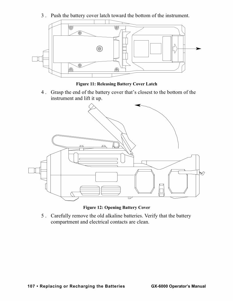
3 . Push the battery cover latch toward the bottom of the instrument.
Figure 11: Releasing Battery Cover Latch
4 . Grasp the end of the battery cover that’s closest to the bottom of the instrument and lift it up.
Figure 12: Opening Battery Cover
5 . Carefully remove the old alkaline batteries. Verify that the battery compartment and electrical contacts are clean.
107 • Replacing or Recharging the Batteries GX-6000 Operator’s Manual
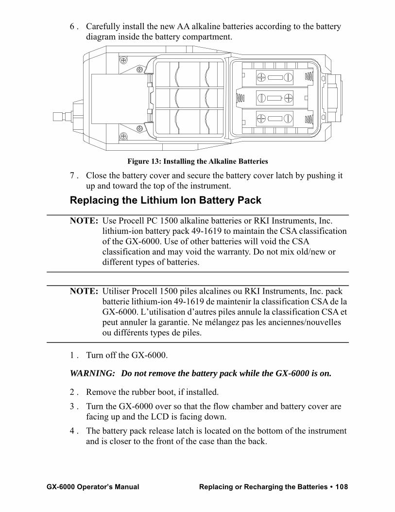
6 . Carefully install the new AA alkaline batteries according to the battery diagram inside the battery compartment.
Figure 13: Installing the Alkaline Batteries
7 . Close the battery cover and secure the battery cover latch by pushing it up and toward the top of the instrument.
Replacing the Lithium Ion Battery Pack
NOTE: Use Procell PC 1500 alkaline batteries or RKI Instruments, Inc. lithium-ion battery pack 49-1619 to maintain the CSA classification of the GX-6000. Use of other batteries will void the CSA classification and may void the warranty. Do not mix old/new or different types of batteries.
NOTE: Utiliser Procell 1500 piles alcalines ou RKI Instruments, Inc. pack batterie lithium-ion 49-1619 de maintenir la classification CSA de la GX-6000. L’utilisation d’autres piles annule la classification CSA et peut annuler la garantie. Ne mélangez pas les anciennes/nouvelles ou différents types de piles.
1 . Turn off the GX-6000.
WARNING: Do not remove the battery pack while the GX-6000 is on.
2 . Remove the rubber boot, if installed.3 . Turn the GX-6000 over so that the flow chamber and battery cover are
facing up and the LCD is facing down.4 . The battery pack release latch is located on the bottom of the instrument
and is closer to the front of the case than the back.
GX-6000 Operator’s Manual Replacing or Recharging the Batteries • 108
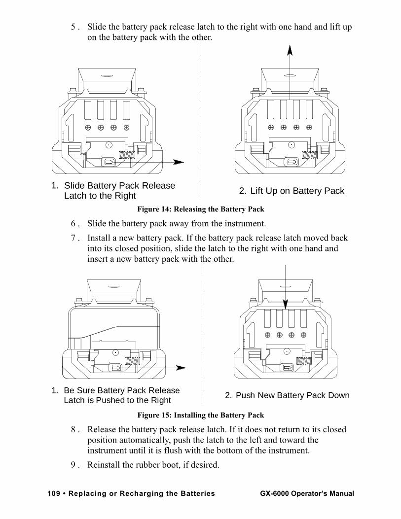
5 . Slide the battery pack release latch to the right with one hand and lift up on the battery pack with the other.
Figure 14: Releasing the Battery Pack
6 . Slide the battery pack away from the instrument.7 . Install a new battery pack. If the battery pack release latch moved back
into its closed position, slide the latch to the right with one hand and insert a new battery pack with the other.
Figure 15: Installing the Battery Pack
8 . Release the battery pack release latch. If it does not return to its closed position automatically, push the latch to the left and toward the instrument until it is flush with the bottom of the instrument.
9 . Reinstall the rubber boot, if desired.
2.1.
Lift Up on Battery PackSlide Battery Pack Release Latch to the Right
2.1. Be Sure Battery Pack Release Latch is Pushed to the Right Push New Battery Pack Down
109 • Replacing or Recharging the Batteries GX-6000 Operator’s Manual
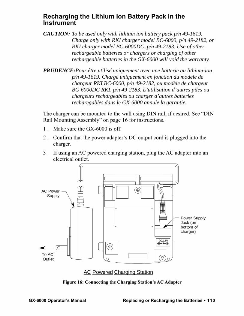
Recharging the Lithium Ion Battery Pack in the InstrumentCAUTION: To be used only with lithium ion battery pack p/n 49-1619.
Charge only with RKI charger model BC-6000, p/n 49-2182, or RKI charger model BC-6000DC, p/n 49-2183. Use of other rechargeable batteries or chargers or charging of other rechargeable batteries in the GX-6000 will void the warranty.
PRUDENCE:Pour être utilisé uniquement avec une batterie au lithium-ion p/n 49-1619. Charge uniquement en fonction du modèle de chargeur RKI BC-6000, p/n 49-2182, ou modèle de chargeur BC-6000DC RKI, p/n 49-2183. L’utilisation d’autres piles ou chargeurs rechargeables ou charger d’autres batteries recharegables dans le GX-6000 annule la garantie.
The charger can be mounted to the wall using DIN rail, if desired. See “DIN Rail Mounting Assembly” on page 16 for instructions.1 . Make sure the GX-6000 is off. 2 . Confirm that the power adapter’s DC output cord is plugged into the
charger. 3 . If using an AC powered charging station, plug the AC adapter into an
electrical outlet.
Figure 16: Connecting the Charging Station’s AC Adapter
To AC Outlet
Power Supply Jack (on bottom of charger)
DC12V
AC Power Supply
AC Powered Charging Station
GX-6000 Operator’s Manual Replacing or Recharging the Batteries • 110
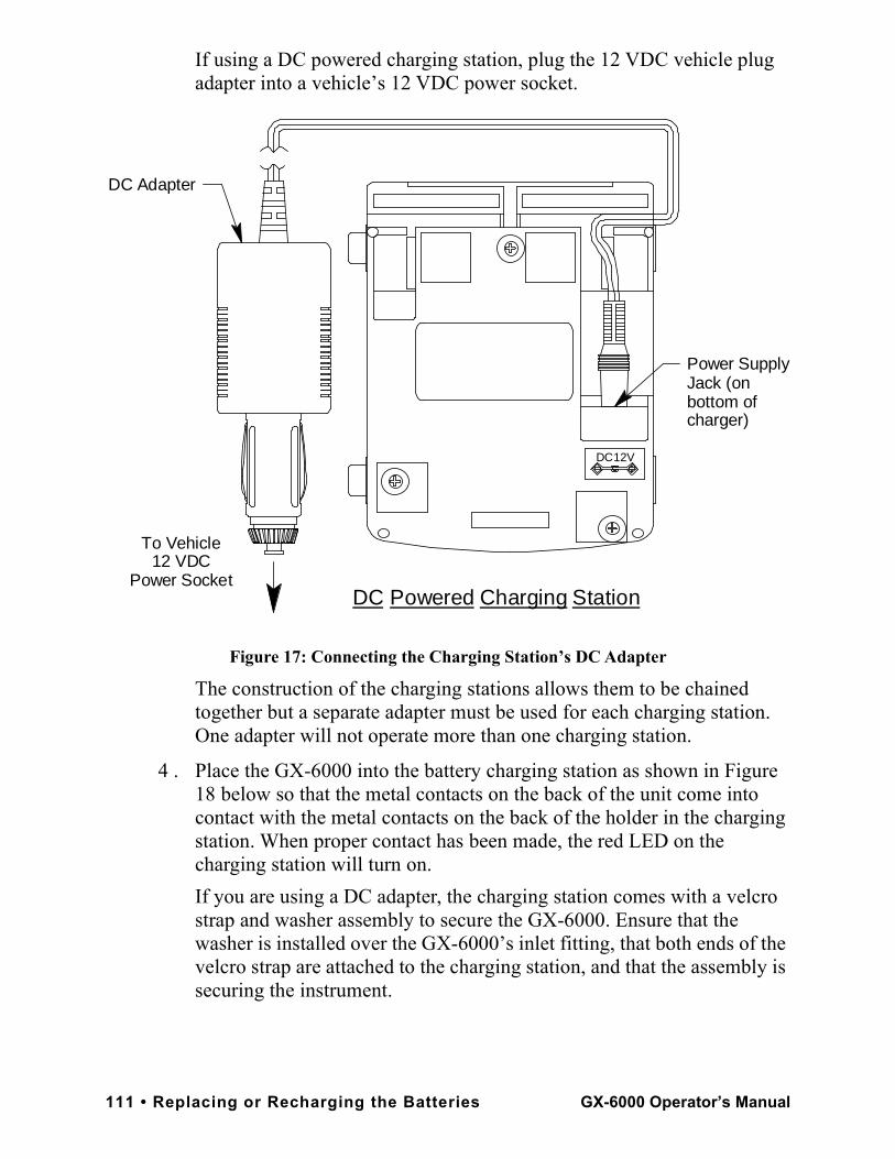
If using a DC powered charging station, plug the 12 VDC vehicle plug adapter into a vehicle’s 12 VDC power socket.
Figure 17: Connecting the Charging Station’s DC Adapter
The construction of the charging stations allows them to be chained together but a separate adapter must be used for each charging station. One adapter will not operate more than one charging station.
4 . Place the GX-6000 into the battery charging station as shown in Figure 18 below so that the metal contacts on the back of the unit come into contact with the metal contacts on the back of the holder in the charging station. When proper contact has been made, the red LED on the charging station will turn on.If you are using a DC adapter, the charging station comes with a velcro strap and washer assembly to secure the GX-6000. Ensure that the washer is installed over the GX-6000’s inlet fitting, that both ends of the velcro strap are attached to the charging station, and that the assembly is securing the instrument.
DC Adapter
To Vehicle12 VDC
Power Socket
DC12V
DC Powered Charging Station
Power Supply Jack (on bottom of charger)
111 • Replacing or Recharging the Batteries GX-6000 Operator’s Manual
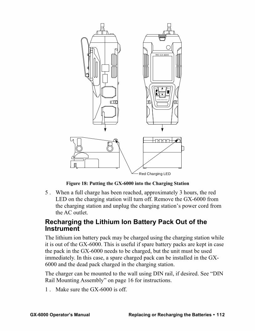
Figure 18: Putting the GX-6000 into the Charging Station
5 . When a full charge has been reached, approximately 3 hours, the red LED on the charging station will turn off. Remove the GX-6000 from the charging station and unplug the charging station’s power cord from the AC outlet.
Recharging the Lithium Ion Battery Pack Out of the InstrumentThe lithium ion battery pack may be charged using the charging station while it is out of the GX-6000. This is useful if spare battery packs are kept in case the pack in the GX-6000 needs to be charged, but the unit must be used immediately. In this case, a spare charged pack can be installed in the GX-6000 and the dead pack charged in the charging station.The charger can be mounted to the wall using DIN rail, if desired. See “DIN Rail Mounting Assembly” on page 16 for instructions.1 . Make sure the GX-6000 is off.
R E SE T
S H IF T
A IR
( P A N IC)
LOC K
DIS P
RKI GX-6000
Red Charging LED
P OW E R /E N TE R
GX-6000 Operator’s Manual Replacing or Recharging the Batteries • 112
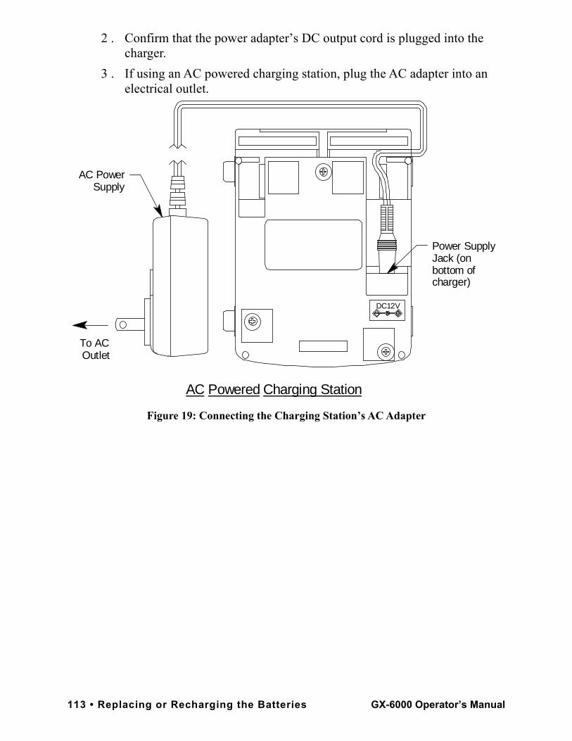
2 . Confirm that the power adapter’s DC output cord is plugged into the charger.
3 . If using an AC powered charging station, plug the AC adapter into an electrical outlet.
Figure 19: Connecting the Charging Station’s AC Adapter
To AC Outlet
Power Supply Jack (on bottom of charger)
DC12V
AC Power Supply
AC Powered Charging Station
113 • Replacing or Recharging the Batteries GX-6000 Operator’s Manual
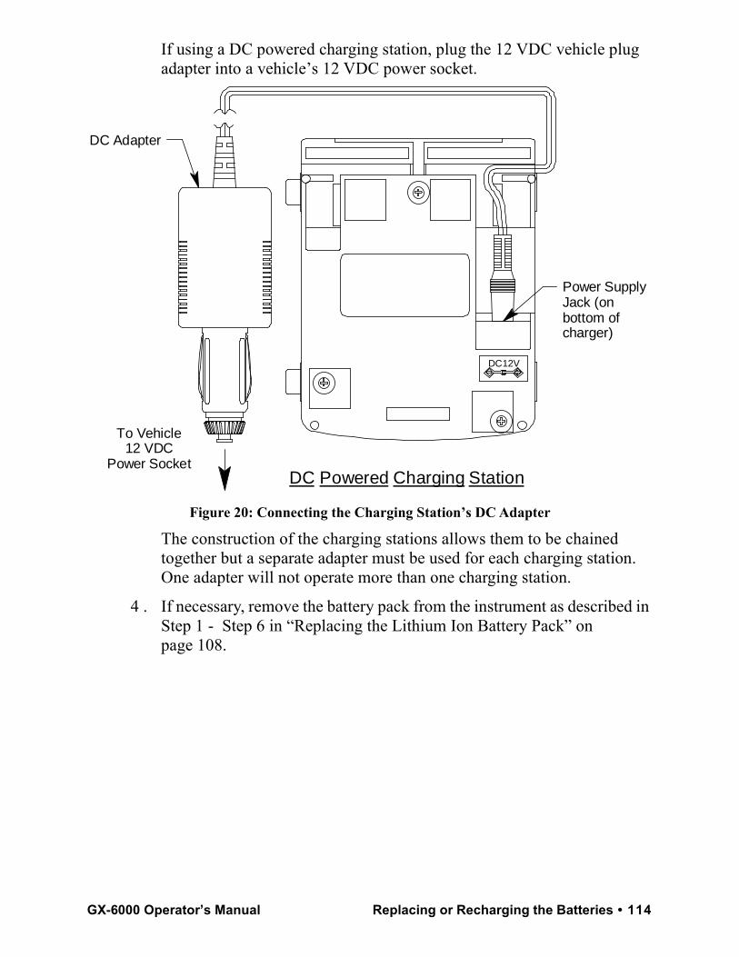
If using a DC powered charging station, plug the 12 VDC vehicle plug adapter into a vehicle’s 12 VDC power socket.
Figure 20: Connecting the Charging Station’s DC Adapter
The construction of the charging stations allows them to be chained together but a separate adapter must be used for each charging station. One adapter will not operate more than one charging station.
4 . If necessary, remove the battery pack from the instrument as described in Step 1 - Step 6 in “Replacing the Lithium Ion Battery Pack” on page 108.
DC Adapter
To Vehicle12 VDC
Power Socket
DC12V
DC Powered Charging Station
Power Supply Jack (on bottom of charger)
GX-6000 Operator’s Manual Replacing or Recharging the Batteries • 114
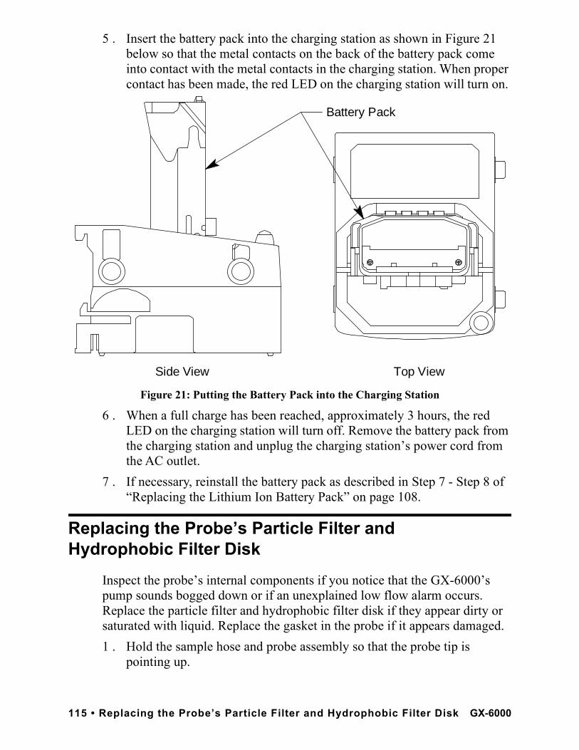
5 . Insert the battery pack into the charging station as shown in Figure 21 below so that the metal contacts on the back of the battery pack come into contact with the metal contacts in the charging station. When proper contact has been made, the red LED on the charging station will turn on.
Figure 21: Putting the Battery Pack into the Charging Station
6 . When a full charge has been reached, approximately 3 hours, the red LED on the charging station will turn off. Remove the battery pack from the charging station and unplug the charging station’s power cord from the AC outlet.
7 . If necessary, reinstall the battery pack as described in Step 7 - Step 8 of “Replacing the Lithium Ion Battery Pack” on page 108.
Replacing the Probe’s Particle Filter and Hydrophobic Filter Disk
Inspect the probe’s internal components if you notice that the GX-6000’s pump sounds bogged down or if an unexplained low flow alarm occurs. Replace the particle filter and hydrophobic filter disk if they appear dirty or saturated with liquid. Replace the gasket in the probe if it appears damaged.1 . Hold the sample hose and probe assembly so that the probe tip is
pointing up.
Side View Top View
Battery Pack
115 • Replacing the Probe’s Particle Filter and Hydrophobic Filter Disk GX-6000
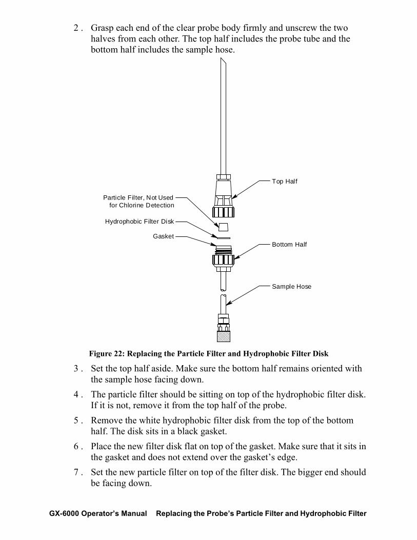
2 . Grasp each end of the clear probe body firmly and unscrew the two halves from each other. The top half includes the probe tube and the bottom half includes the sample hose.
Figure 22: Replacing the Particle Filter and Hydrophobic Filter Disk
3 . Set the top half aside. Make sure the bottom half remains oriented with the sample hose facing down.
4 . The particle filter should be sitting on top of the hydrophobic filter disk. If it is not, remove it from the top half of the probe.
5 . Remove the white hydrophobic filter disk from the top of the bottom half. The disk sits in a black gasket.
6 . Place the new filter disk flat on top of the gasket. Make sure that it sits in the gasket and does not extend over the gasket’s edge.
7 . Set the new particle filter on top of the filter disk. The bigger end should be facing down.
Bottom HalfGasket
Hydrophobic Filter Disk
Sample Hose
Top Half
Particle Filter, Not Used for Chlorine Detection
GX-6000 Operator’s Manual Replacing the Probe’s Particle Filter and Hydrophobic Filter
CAUTION: If you are replacing filters in a probe intended for chlorine detection, do not install the particle filter.
8 . Carefully screw the top half onto the bottom half disk while keeping the probe oriented with the probe tip facing up and the sample hose facing down. The particle filter fits into a recess in the top half of the probe. Be sure the particle filter is not compressed in any way.
9 . Tighten the halves together very firmly to ensure a seal.10 . To test the seal, do the following.
a. Install the probe on the GX-6000.
b. Startup the GX-6000.
c. Confirm that a low flow alarm occurs when you cover the end of the probe tube with your finger.
d. If a low flow alarm does not occur, hand tighten the probe further.
e. If a low flow alarm still does not occur when you cover the probe tube with your finger, disassemble the probe, inspect the placement of the hydrophobic filter disk, reassemble the probe, and re-test it.
Replacing the H2S Scrubber Disk and the Charcoal Filter
The H2S filter disk is dark red in color and although it may darken over time, its color is not indicative of remaining filter life. The H2S filter disk can absorb H2S for 33 ppm hours and should be replaced after that much exposure. With this many ppm hours of absorption, the H2S filter disk should be replaced after 80 minutes of exposure to 25 ppm H2S. This equates to replacing the H2S filter disk after 40 2-minute calibrations with a cylinder containing 25 ppm H2S. If H2S exists in the monitoring environment, the H2S filter disk will have to be replaced more frequently.
1 . Verify that the GX-6000 is off.2 . Use a small Phillips screwdriver to unscrew the four screws holding the
flow chamber to the rest of the GX-6000’s case.3 . Grasp the sides of the flow chamber and lift it away from the rest of the
case. The screws are captive screws and will not come out of the flow chamber.
117 • Replacing the H2S Scrubber Disk and the Charcoal Filter GX-6000 Operator’s
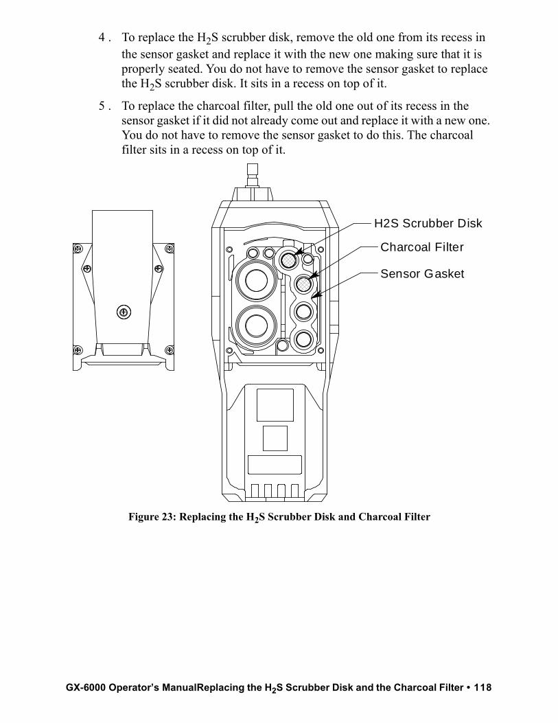
4 . To replace the H2S scrubber disk, remove the old one from its recess in the sensor gasket and replace it with the new one making sure that it is properly seated. You do not have to remove the sensor gasket to replace the H2S scrubber disk. It sits in a recess on top of it.
5 . To replace the charcoal filter, pull the old one out of its recess in the sensor gasket if it did not already come out and replace it with a new one. You do not have to remove the sensor gasket to do this. The charcoal filter sits in a recess on top of it.
Figure 23: Replacing the H2S Scrubber Disk and Charcoal Filter
Charcoal Filter
Sensor Gasket
H2S Scrubber Disk
GX-6000 Operator’s ManualReplacing the H2S Scrubber Disk and the Charcoal Filter • 118
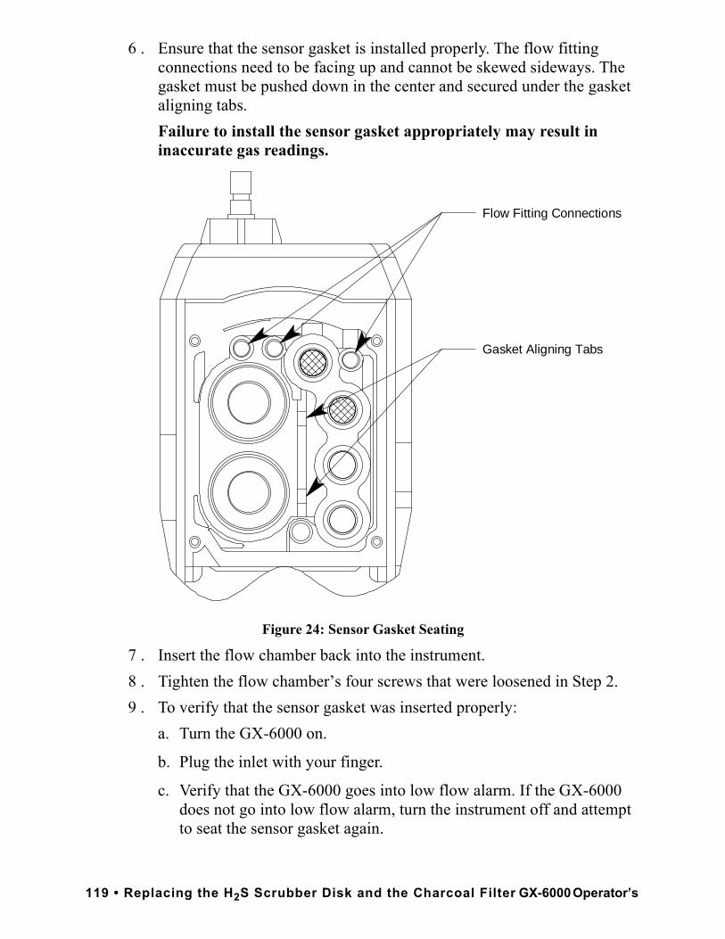
6 . Ensure that the sensor gasket is installed properly. The flow fitting connections need to be facing up and cannot be skewed sideways. The gasket must be pushed down in the center and secured under the gasket aligning tabs.Failure to install the sensor gasket appropriately may result in inaccurate gas readings.
Figure 24: Sensor Gasket Seating
7 . Insert the flow chamber back into the instrument.8 . Tighten the flow chamber’s four screws that were loosened in Step 2.9 . To verify that the sensor gasket was inserted properly:
a. Turn the GX-6000 on.
b. Plug the inlet with your finger.
c. Verify that the GX-6000 goes into low flow alarm. If the GX-6000 does not go into low flow alarm, turn the instrument off and attempt to seat the sensor gasket again.
Gasket Aligning Tabs
Flow Fitting Connections
119 • Replacing the H2S Scrubber Disk and the Charcoal Filter GX-6000 Operator’s
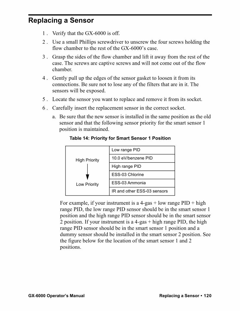
Replacing a Sensor1 . Verify that the GX-6000 is off.2 . Use a small Phillips screwdriver to unscrew the four screws holding the
flow chamber to the rest of the GX-6000’s case.3 . Grasp the sides of the flow chamber and lift it away from the rest of the
case. The screws are captive screws and will not come out of the flow chamber.
4 . Gently pull up the edges of the sensor gasket to loosen it from its connections. Be sure not to lose any of the filters that are in it. The sensors will be exposed.
5 . Locate the sensor you want to replace and remove it from its socket.6 . Carefully insert the replacement sensor in the correct socket.
a. Be sure that the new sensor is installed in the same position as the old sensor and that the following sensor priority for the smart sensor 1 position is maintained.
Table 14: Priority for Smart Sensor 1 Position
For example, if your instrument is a 4-gas + low range PID + high range PID, the low range PID sensor should be in the smart sensor 1 position and the high range PID sensor should be in the smart sensor 2 position. If your instrument is a 4-gas + high range PID, the high range PID sensor should be in the smart sensor 1 position and a dummy sensor should be installed in the smart sensor 2 position. See the figure below for the location of the smart sensor 1 and 2 positions.
High Priority
Low Priority
Low range PID
10.0 eV/benzene PID
High range PID
ESS-03 Chlorine
ESS-03 Ammonia
IR and other ESS-03 sensors
GX-6000 Operator’s Manual Replacing a Sensor • 120
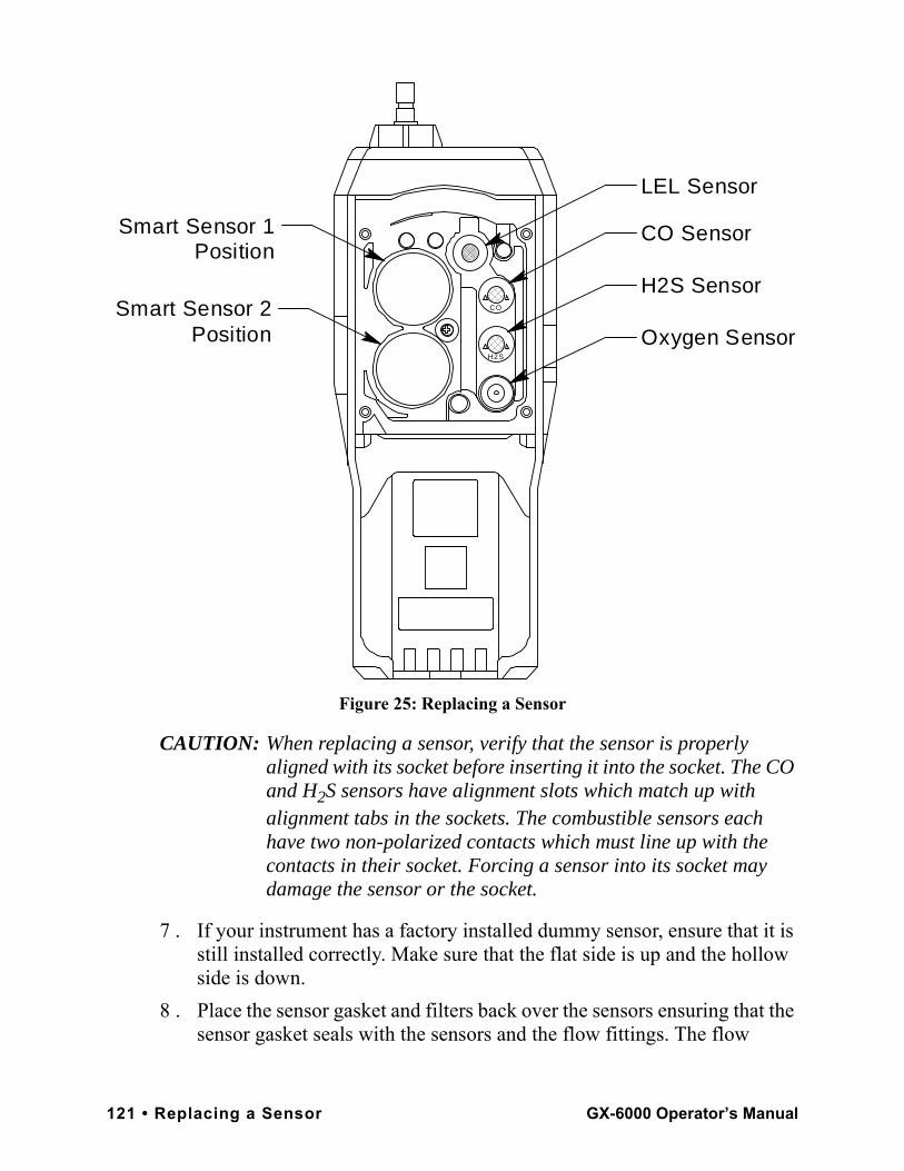
Figure 25: Replacing a Sensor
CAUTION: When replacing a sensor, verify that the sensor is properly aligned with its socket before inserting it into the socket. The CO and H2S sensors have alignment slots which match up with alignment tabs in the sockets. The combustible sensors each have two non-polarized contacts which must line up with the contacts in their socket. Forcing a sensor into its socket may damage the sensor or the socket.
7 . If your instrument has a factory installed dummy sensor, ensure that it is still installed correctly. Make sure that the flat side is up and the hollow side is down.
8 . Place the sensor gasket and filters back over the sensors ensuring that the sensor gasket seals with the sensors and the flow fittings. The flow
CO Sensor
H2S Sensor
Oxygen SensorH2S
CO
LEL Sensor
Smart Sensor 2 Position
Smart Sensor 1 Position
121 • Replacing a Sensor GX-6000 Operator’s Manual
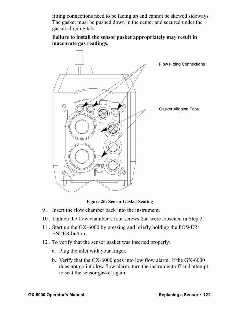
fitting connections need to be facing up and cannot be skewed sideways. The gasket must be pushed down in the center and secured under the gasket aligning tabs.Failure to install the sensor gasket appropriately may result in inaccurate gas readings.
Figure 26: Sensor Gasket Seating
9 . Insert the flow chamber back into the instrument.10 . Tighten the flow chamber’s four screws that were loosened in Step 2.11 . Start up the GX-6000 by pressing and briefly holding the POWER/
ENTER button.12 . To verify that the sensor gasket was inserted properly:
a. Plug the inlet with your finger.
b. Verify that the GX-6000 goes into low flow alarm. If the GX-6000 does not go into low flow alarm, turn the instrument off and attempt to seat the sensor gasket again.
Gasket Aligning Tabs
Flow Fitting Connections
GX-6000 Operator’s Manual Replacing a Sensor • 122
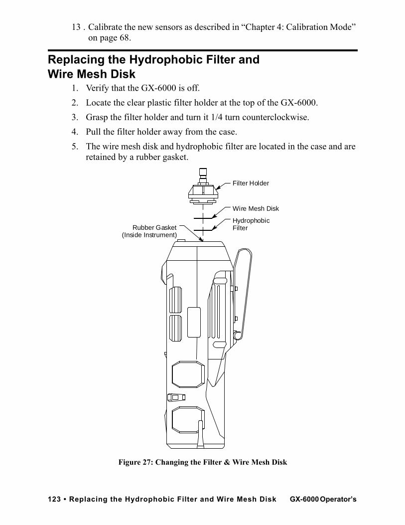
13 . Calibrate the new sensors as described in “Chapter 4: Calibration Mode” on page 68.
Replacing the Hydrophobic Filter and Wire Mesh Disk
1. Verify that the GX-6000 is off.2. Locate the clear plastic filter holder at the top of the GX-6000. 3. Grasp the filter holder and turn it 1/4 turn counterclockwise.4. Pull the filter holder away from the case. 5. The wire mesh disk and hydrophobic filter are located in the case and are
retained by a rubber gasket.
Figure 27: Changing the Filter & Wire Mesh Disk
Rubber Gasket(Inside Instrument)
Filter Holder
Hydrophobic Filter
Wire Mesh Disk
123 • Replacing the Hydrophobic Filter and Wire Mesh Disk GX-6000 Operator’s
6. Using a small flat head screwdriver, carefully pry the wire mesh disk and hydrophobic filter from the gasket. Do not remove the gasket.
7. Carefully install the new hydrophobic filter and/or wire mesh disk making sure the wire mesh disk is on top of the hydrophobic filter.
8. Reinstall the filter holder. Align the two wide tabs on the bottom of the filter holder with the two wide slots in the case where the filter holder fits. Push the filter holder into the case and turn it 1/4 turn clockwise until it snaps into place.
PID Sensor MaintenanceThe PID sensor includes user serviceable parts. They are the lamp and the electrode stack. The following sections include procedures for cleaning the lamp, replacing the lamp, and replacing the electrode stack.Cleaning the PID Sensor’s LampClean the lamp if you notice a significant drop in sensitivity from one scheduled calibration to another or if you are not able to calibrate the PID channel. See the Table 16 on page 137 for lamp cleaning kit ordering information. The lamp cleaning kit includes the following items:
• an electrode stack removal tool
• a small vial of aluminum oxide powder
• 40 cotton swabs
• 10 finger cots
Perform the following procedure to clean the PID lamp:1 . Verify that the GX-6000 is off.2 . Use a small Phillips screwdriver to unscrew the four screws holding the
flow chamber to the rest of the GX-6000’s case.3 . Grasp the sides of the flow chamber and lift it away from the rest of the
case. The screws are captive screws and will not come out of the flow chamber.
4 . Gently pull up the edges of the sensor gasket to loosen it from its connections. Be sure not to lose any of the filters that are in it. The sensors will be exposed.
5 . Locate the PID sensor.6 . Grasp the sensor firmly and pull it out of its socket.
GX-6000 Operator’s Manual PID Sensor Maintenance • 124
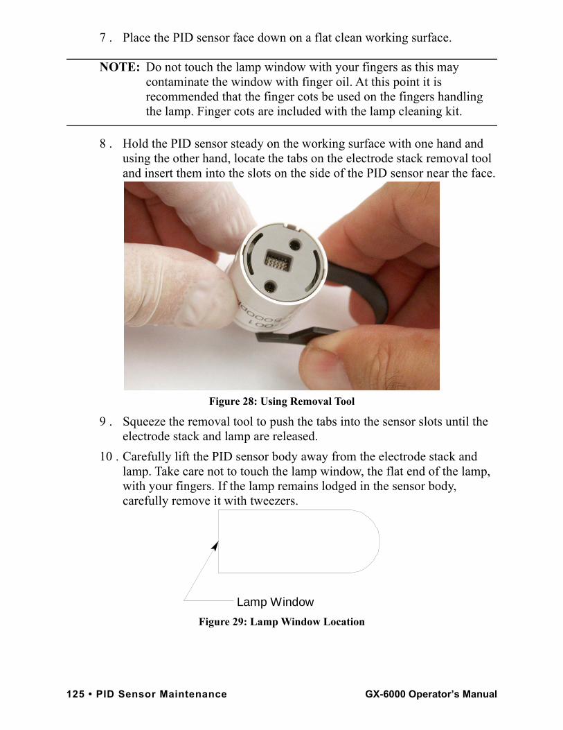
7 . Place the PID sensor face down on a flat clean working surface.
NOTE: Do not touch the lamp window with your fingers as this may contaminate the window with finger oil. At this point it is recommended that the finger cots be used on the fingers handling the lamp. Finger cots are included with the lamp cleaning kit.
8 . Hold the PID sensor steady on the working surface with one hand and using the other hand, locate the tabs on the electrode stack removal tool and insert them into the slots on the side of the PID sensor near the face.
Figure 28: Using Removal Tool
9 . Squeeze the removal tool to push the tabs into the sensor slots until the electrode stack and lamp are released.
10 . Carefully lift the PID sensor body away from the electrode stack and lamp. Take care not to touch the lamp window, the flat end of the lamp, with your fingers. If the lamp remains lodged in the sensor body, carefully remove it with tweezers.
Figure 29: Lamp Window Location
Lamp Window
125 • PID Sensor Maintenance GX-6000 Operator’s Manual
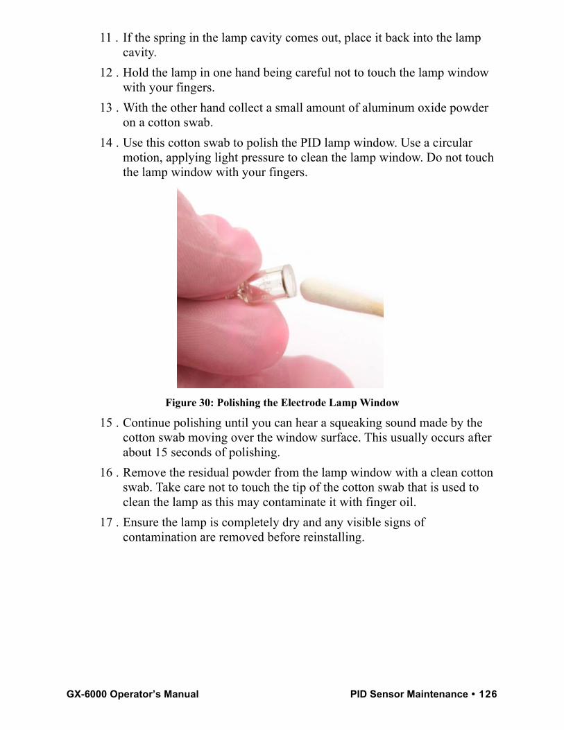
11 . If the spring in the lamp cavity comes out, place it back into the lamp cavity.
12 . Hold the lamp in one hand being careful not to touch the lamp window with your fingers.
13 . With the other hand collect a small amount of aluminum oxide powder on a cotton swab.
14 . Use this cotton swab to polish the PID lamp window. Use a circular motion, applying light pressure to clean the lamp window. Do not touch the lamp window with your fingers.
Figure 30: Polishing the Electrode Lamp Window
15 . Continue polishing until you can hear a squeaking sound made by the cotton swab moving over the window surface. This usually occurs after about 15 seconds of polishing.
16 . Remove the residual powder from the lamp window with a clean cotton swab. Take care not to touch the tip of the cotton swab that is used to clean the lamp as this may contaminate it with finger oil.
17 . Ensure the lamp is completely dry and any visible signs of contamination are removed before reinstalling.
GX-6000 Operator’s Manual PID Sensor Maintenance • 126
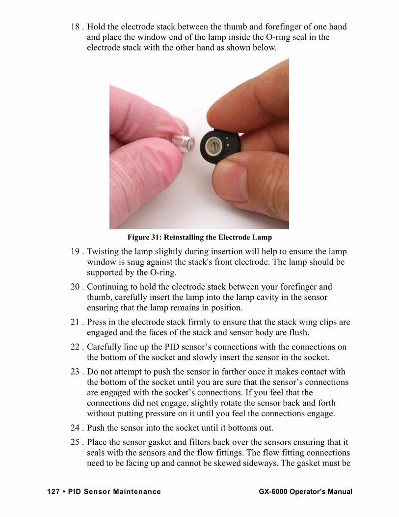
18 . Hold the electrode stack between the thumb and forefinger of one hand and place the window end of the lamp inside the O-ring seal in the electrode stack with the other hand as shown below.
Figure 31: Reinstalling the Electrode Lamp
19 . Twisting the lamp slightly during insertion will help to ensure the lamp window is snug against the stack's front electrode. The lamp should be supported by the O-ring.
20 . Continuing to hold the electrode stack between your forefinger and thumb, carefully insert the lamp into the lamp cavity in the sensor ensuring that the lamp remains in position.
21 . Press in the electrode stack firmly to ensure that the stack wing clips are engaged and the faces of the stack and sensor body are flush.
22 . Carefully line up the PID sensor’s connections with the connections on the bottom of the socket and slowly insert the sensor in the socket.
23 . Do not attempt to push the sensor in farther once it makes contact with the bottom of the socket until you are sure that the sensor’s connections are engaged with the socket’s connections. If you feel that the connections did not engage, slightly rotate the sensor back and forth without putting pressure on it until you feel the connections engage.
24 . Push the sensor into the socket until it bottoms out.25 . Place the sensor gasket and filters back over the sensors ensuring that it
seals with the sensors and the flow fittings. The flow fitting connections need to be facing up and cannot be skewed sideways. The gasket must be
127 • PID Sensor Maintenance GX-6000 Operator’s Manual
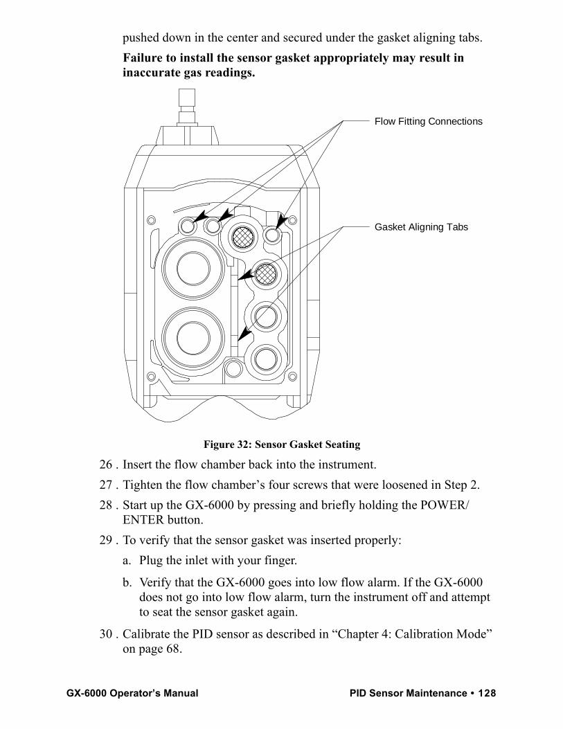
pushed down in the center and secured under the gasket aligning tabs.Failure to install the sensor gasket appropriately may result in inaccurate gas readings.
Figure 32: Sensor Gasket Seating
26 . Insert the flow chamber back into the instrument.27 . Tighten the flow chamber’s four screws that were loosened in Step 2.28 . Start up the GX-6000 by pressing and briefly holding the POWER/
ENTER button.29 . To verify that the sensor gasket was inserted properly:
a. Plug the inlet with your finger.
b. Verify that the GX-6000 goes into low flow alarm. If the GX-6000 does not go into low flow alarm, turn the instrument off and attempt to seat the sensor gasket again.
30 . Calibrate the PID sensor as described in “Chapter 4: Calibration Mode” on page 68.
Gasket Aligning Tabs
Flow Fitting Connections
GX-6000 Operator’s Manual PID Sensor Maintenance • 128
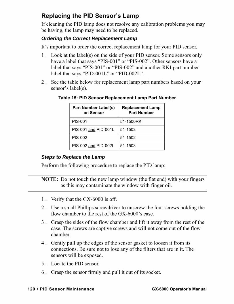
Replacing the PID Sensor’s LampIf cleaning the PID lamp does not resolve any calibration problems you may be having, the lamp may need to be replaced. Ordering the Correct Replacement LampIt’s important to order the correct replacement lamp for your PID sensor.1 . Look at the label(s) on the side of your PID sensor. Some sensors only
have a label that says “PIS-001” or “PIS-002”. Other sensors have a label that says “PIS-001” or “PIS-002” and another RKI part number label that says “PID-001L” or “PID-002L”.
2 . See the table below for replacement lamp part numbers based on your sensor’s label(s).
Steps to Replace the LampPerform the following procedure to replace the PID lamp:
NOTE: Do not touch the new lamp window (the flat end) with your fingers as this may contaminate the window with finger oil.
1 . Verify that the GX-6000 is off.2 . Use a small Phillips screwdriver to unscrew the four screws holding the
flow chamber to the rest of the GX-6000’s case.3 . Grasp the sides of the flow chamber and lift it away from the rest of the
case. The screws are captive screws and will not come out of the flow chamber.
4 . Gently pull up the edges of the sensor gasket to loosen it from its connections. Be sure not to lose any of the filters that are in it. The sensors will be exposed.
5 . Locate the PID sensor.6 . Grasp the sensor firmly and pull it out of its socket.
Table 15: PID Sensor Replacement Lamp Part Number
Part Number Label(s) on Sensor
Replacement Lamp Part Number
PIS-001 51-1500RK
PIS-001 and PID-001L 51-1503
PIS-002 51-1502
PIS-002 and PID-002L 51-1503
129 • PID Sensor Maintenance GX-6000 Operator’s Manual
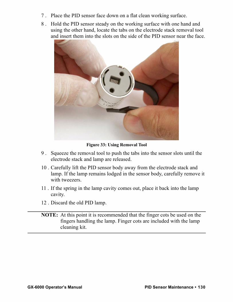
7 . Place the PID sensor face down on a flat clean working surface.8 . Hold the PID sensor steady on the working surface with one hand and
using the other hand, locate the tabs on the electrode stack removal tool and insert them into the slots on the side of the PID sensor near the face.
Figure 33: Using Removal Tool
9 . Squeeze the removal tool to push the tabs into the sensor slots until the electrode stack and lamp are released.
10 . Carefully lift the PID sensor body away from the electrode stack and lamp. If the lamp remains lodged in the sensor body, carefully remove it with tweezers.
11 . If the spring in the lamp cavity comes out, place it back into the lamp cavity.
12 . Discard the old PID lamp.
NOTE: At this point it is recommended that the finger cots be used on the fingers handling the lamp. Finger cots are included with the lamp cleaning kit.
GX-6000 Operator’s Manual PID Sensor Maintenance • 130
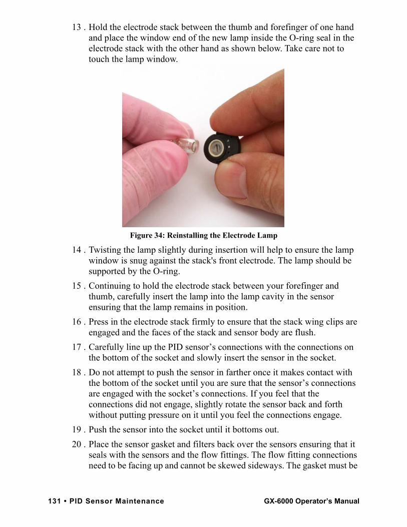
13 . Hold the electrode stack between the thumb and forefinger of one hand and place the window end of the new lamp inside the O-ring seal in the electrode stack with the other hand as shown below. Take care not to touch the lamp window.
Figure 34: Reinstalling the Electrode Lamp
14 . Twisting the lamp slightly during insertion will help to ensure the lamp window is snug against the stack's front electrode. The lamp should be supported by the O-ring.
15 . Continuing to hold the electrode stack between your forefinger and thumb, carefully insert the lamp into the lamp cavity in the sensor ensuring that the lamp remains in position.
16 . Press in the electrode stack firmly to ensure that the stack wing clips are engaged and the faces of the stack and sensor body are flush.
17 . Carefully line up the PID sensor’s connections with the connections on the bottom of the socket and slowly insert the sensor in the socket.
18 . Do not attempt to push the sensor in farther once it makes contact with the bottom of the socket until you are sure that the sensor’s connections are engaged with the socket’s connections. If you feel that the connections did not engage, slightly rotate the sensor back and forth without putting pressure on it until you feel the connections engage.
19 . Push the sensor into the socket until it bottoms out.20 . Place the sensor gasket and filters back over the sensors ensuring that it
seals with the sensors and the flow fittings. The flow fitting connections need to be facing up and cannot be skewed sideways. The gasket must be
131 • PID Sensor Maintenance GX-6000 Operator’s Manual

pushed down in the center and secured under the gasket aligning tabs.Failure to install the sensor gasket appropriately may result in inaccurate gas readings.
Figure 35: Sensor Gasket Seating
21 . Insert the flow chamber back into the instrument.22 . Tighten the flow chamber’s four screws that were loosened in Step 2.23 . Start up the GX-6000 by pressing and briefly holding the POWER/
ENTER button.24 . To verify that the sensor gasket was inserted properly:
a. Plug the inlet with your finger.
b. Verify that the GX-6000 goes into low flow alarm. If the GX-6000 does not go into low flow alarm, turn the instrument off and attempt to seat the sensor gasket again.
25 . Calibrate the PID sensor as described in “Chapter 4: Calibration Mode” on page 68.
Gasket Aligning Tabs
Flow Fitting Connections
GX-6000 Operator’s Manual PID Sensor Maintenance • 132
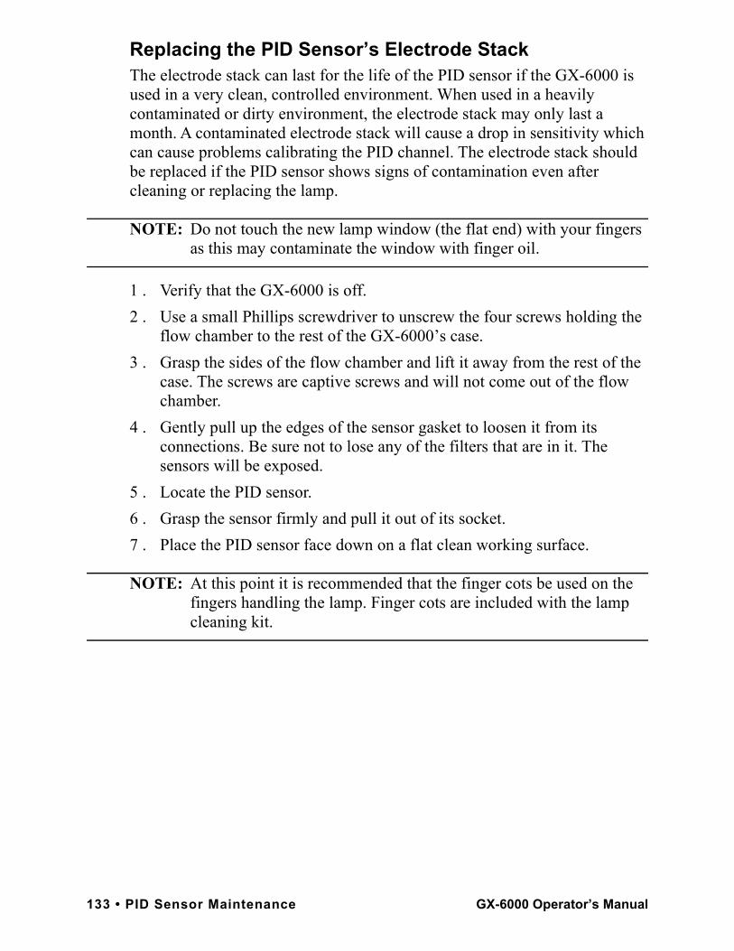
Replacing the PID Sensor’s Electrode StackThe electrode stack can last for the life of the PID sensor if the GX-6000 is used in a very clean, controlled environment. When used in a heavily contaminated or dirty environment, the electrode stack may only last a month. A contaminated electrode stack will cause a drop in sensitivity which can cause problems calibrating the PID channel. The electrode stack should be replaced if the PID sensor shows signs of contamination even after cleaning or replacing the lamp.
NOTE: Do not touch the new lamp window (the flat end) with your fingers as this may contaminate the window with finger oil.
1 . Verify that the GX-6000 is off.2 . Use a small Phillips screwdriver to unscrew the four screws holding the
flow chamber to the rest of the GX-6000’s case.3 . Grasp the sides of the flow chamber and lift it away from the rest of the
case. The screws are captive screws and will not come out of the flow chamber.
4 . Gently pull up the edges of the sensor gasket to loosen it from its connections. Be sure not to lose any of the filters that are in it. The sensors will be exposed.
5 . Locate the PID sensor.6 . Grasp the sensor firmly and pull it out of its socket.7 . Place the PID sensor face down on a flat clean working surface.
NOTE: At this point it is recommended that the finger cots be used on the fingers handling the lamp. Finger cots are included with the lamp cleaning kit.
133 • PID Sensor Maintenance GX-6000 Operator’s Manual
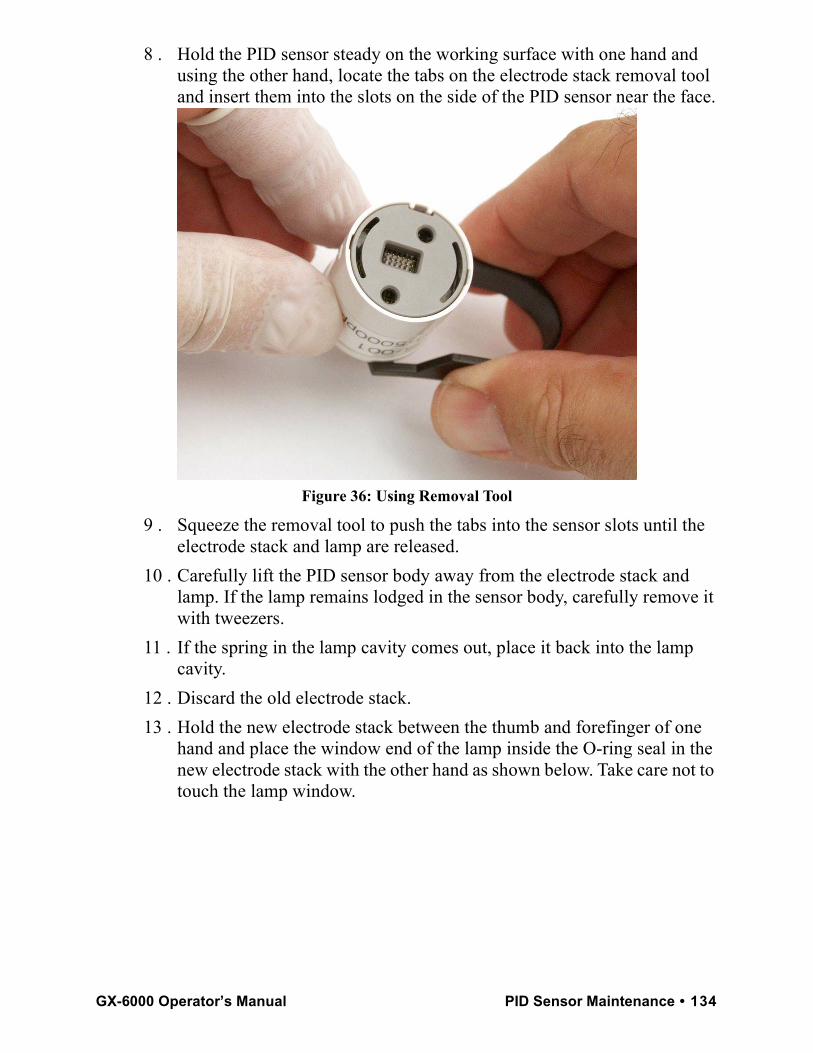
8 . Hold the PID sensor steady on the working surface with one hand and using the other hand, locate the tabs on the electrode stack removal tool and insert them into the slots on the side of the PID sensor near the face.
Figure 36: Using Removal Tool
9 . Squeeze the removal tool to push the tabs into the sensor slots until the electrode stack and lamp are released.
10 . Carefully lift the PID sensor body away from the electrode stack and lamp. If the lamp remains lodged in the sensor body, carefully remove it with tweezers.
11 . If the spring in the lamp cavity comes out, place it back into the lamp cavity.
12 . Discard the old electrode stack.13 . Hold the new electrode stack between the thumb and forefinger of one
hand and place the window end of the lamp inside the O-ring seal in the new electrode stack with the other hand as shown below. Take care not to touch the lamp window.
GX-6000 Operator’s Manual PID Sensor Maintenance • 134
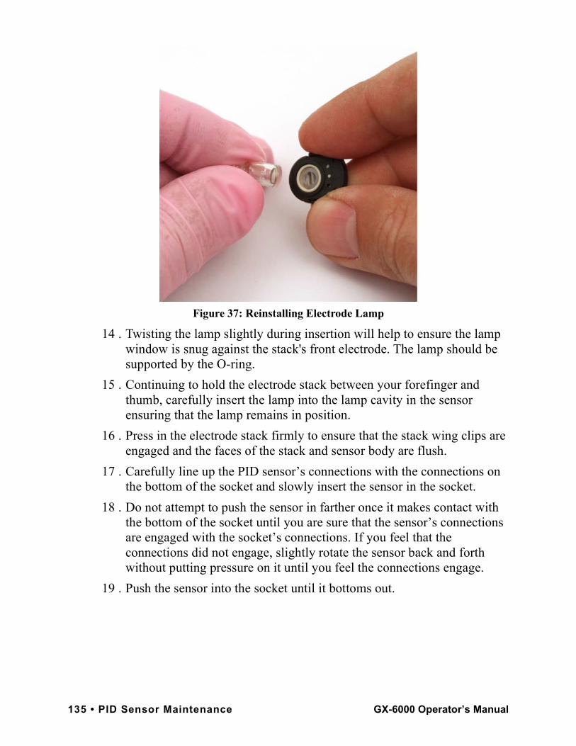
Figure 37: Reinstalling Electrode Lamp
14 . Twisting the lamp slightly during insertion will help to ensure the lamp window is snug against the stack's front electrode. The lamp should be supported by the O-ring.
15 . Continuing to hold the electrode stack between your forefinger and thumb, carefully insert the lamp into the lamp cavity in the sensor ensuring that the lamp remains in position.
16 . Press in the electrode stack firmly to ensure that the stack wing clips are engaged and the faces of the stack and sensor body are flush.
17 . Carefully line up the PID sensor’s connections with the connections on the bottom of the socket and slowly insert the sensor in the socket.
18 . Do not attempt to push the sensor in farther once it makes contact with the bottom of the socket until you are sure that the sensor’s connections are engaged with the socket’s connections. If you feel that the connections did not engage, slightly rotate the sensor back and forth without putting pressure on it until you feel the connections engage.
19 . Push the sensor into the socket until it bottoms out.
135 • PID Sensor Maintenance GX-6000 Operator’s Manual
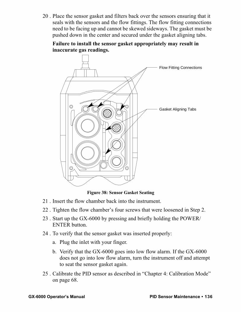
20 . Place the sensor gasket and filters back over the sensors ensuring that it seals with the sensors and the flow fittings. The flow fitting connections need to be facing up and cannot be skewed sideways. The gasket must be pushed down in the center and secured under the gasket aligning tabs.Failure to install the sensor gasket appropriately may result in inaccurate gas readings.
Figure 38: Sensor Gasket Seating
21 . Insert the flow chamber back into the instrument.22 . Tighten the flow chamber’s four screws that were loosened in Step 2.23 . Start up the GX-6000 by pressing and briefly holding the POWER/
ENTER button.24 . To verify that the sensor gasket was inserted properly:
a. Plug the inlet with your finger.
b. Verify that the GX-6000 goes into low flow alarm. If the GX-6000 does not go into low flow alarm, turn the instrument off and attempt to seat the sensor gasket again.
25 . Calibrate the PID sensor as described in “Chapter 4: Calibration Mode” on page 68.
Gasket Aligning Tabs
Flow Fitting Connections
GX-6000 Operator’s Manual PID Sensor Maintenance • 136
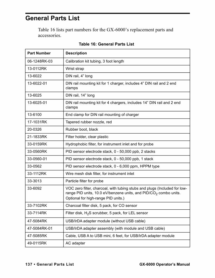
General Parts ListTable 16 lists part numbers for the GX-6000’s replacement parts and accessories.
Table 16: General Parts List
Part Number Description
06-1248RK-03 Calibration kit tubing, 3 foot length
13-0112RK Wrist strap
13-6022 DIN rail, 4” long
13-6022-01 DIN rail mounting kit for 1 charger, includes 4” DIN rail and 2 end clamps
13-6025 DIN rail, 14” long
13-6025-01 DIN rail mounting kit for 4 chargers, includes 14” DIN rail and 2 end clamps
13-6100 End clamp for DIN rail mounting of charger
17-1031RK Tapered rubber nozzle, red
20-0326 Rubber boot, black
21-1833RK Filter holder, clear plastic
33-0159RK Hydrophobic filter, for instrument inlet and for probe
33-0560RK PID sensor electrode stack, 0 - 50,000 ppb, 2 stacks
33-0560-01 PID sensor electrode stack, 0 - 50,000 ppb, 1 stack
33-0562 PID sensor electrode stack, 0 - 6,000 ppm, HPPM type
33-1112RK Wire mesh disk filter, for instrument inlet
33-3013 Particle filter for probe
33-6092 VOC zero filter, charcoal, with tubing stubs and plugs (Included for low-range PID units, 10.0 eV/benzene units, and PID/CO2 combo units. Optional for high-range PID units.)
33-7102RK Charcoal filter disk, 5 pack, for CO sensor
33-7114RK Filter disk, H2S scrubber, 5 pack, for LEL sensor
47-5084RK USB/IrDA adapter module (without USB cable)
47-5084RK-01 USB/IrDA adapter assembly (with module and USB cable)
47-5085RK Cable, USB A to USB mini, 6 feet, for USB/IrDA adapter module
49-0115RK AC adapter
137 • General Parts List GX-6000 Operator’s Manual
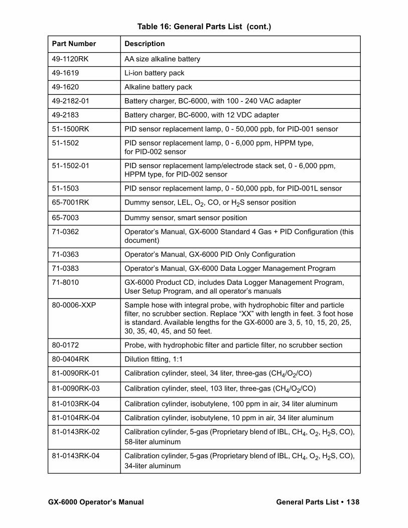
49-1120RK AA size alkaline battery
49-1619 Li-ion battery pack
49-1620 Alkaline battery pack
49-2182-01 Battery charger, BC-6000, with 100 - 240 VAC adapter
49-2183 Battery charger, BC-6000, with 12 VDC adapter
51-1500RK PID sensor replacement lamp, 0 - 50,000 ppb, for PID-001 sensor
51-1502 PID sensor replacement lamp, 0 - 6,000 ppm, HPPM type, for PID-002 sensor
51-1502-01 PID sensor replacement lamp/electrode stack set, 0 - 6,000 ppm, HPPM type, for PID-002 sensor
51-1503 PID sensor replacement lamp, 0 - 50,000 ppb, for PID-001L sensor
65-7001RK Dummy sensor, LEL, O2, CO, or H2S sensor position
65-7003 Dummy sensor, smart sensor position
71-0362 Operator’s Manual, GX-6000 Standard 4 Gas + PID Configuration (this document)
71-0363 Operator’s Manual, GX-6000 PID Only Configuration
71-0383 Operator’s Manual, GX-6000 Data Logger Management Program
71-8010 GX-6000 Product CD, includes Data Logger Management Program, User Setup Program, and all operator’s manuals
80-0006-XXP Sample hose with integral probe, with hydrophobic filter and particle filter, no scrubber section. Replace “XX” with length in feet. 3 foot hose is standard. Available lengths for the GX-6000 are 3, 5, 10, 15, 20, 25, 30, 35, 40, 45, and 50 feet.
80-0172 Probe, with hydrophobic filter and particle filter, no scrubber section
80-0404RK Dilution fitting, 1:1
81-0090RK-01 Calibration cylinder, steel, 34 liter, three-gas (CH4/O2/CO)
81-0090RK-03 Calibration cylinder, steel, 103 liter, three-gas (CH4/O2/CO)
81-0103RK-04 Calibration cylinder, isobutylene, 100 ppm in air, 34 liter aluminum
81-0104RK-04 Calibration cylinder, isobutylene, 10 ppm in air, 34 liter aluminum
81-0143RK-02 Calibration cylinder, 5-gas (Proprietary blend of IBL, CH4, O2, H2S, CO), 58-liter aluminum
81-0143RK-04 Calibration cylinder, 5-gas (Proprietary blend of IBL, CH4, O2, H2S, CO), 34-liter aluminum
Table 16: General Parts List (cont.)
Part Number Description
GX-6000 Operator’s Manual General Parts List • 138
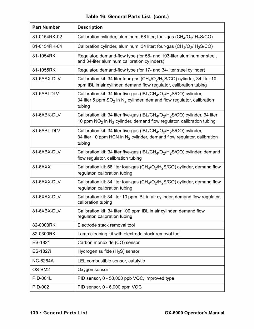
81-0154RK-02 Calibration cylinder, aluminum, 58 liter; four-gas (CH4/O2/ H2S/CO)
81-0154RK-04 Calibration cylinder, aluminum, 34 liter; four-gas (CH4/O2/ H2S/CO)
81-1054RK Regulator, demand-flow type (for 58- and 103-liter aluminum or steel, and 34-liter aluminum calibration cylinders)
81-1055RK Regulator, demand-flow type (for 17- and 34-liter steel cylinder)
81-6AAX-DLV Calibration kit: 34 liter four-gas (CH4/O2/H2S/CO) cylinder, 34 liter 10 ppm IBL in air cylinder, demand flow regulator, calibration tubing
81-6ABI-DLV Calibration kit: 34 liter five-gas (IBL/CH4/O2/H2S/CO) cylinder, 34 liter 5 ppm SO2 in N2 cylinder, demand flow regulator, calibration tubing
81-6ABK-DLV Calibration kit: 34 liter five-gas (IBL/CH4/O2/H2S/CO) cylinder, 34 liter 10 ppm NO2 in N2 cylinder, demand flow regulator, calibration tubing
81-6ABL-DLV Calibration kit: 34 liter five-gas (IBL/CH4/O2/H2S/CO) cylinder, 34 liter 10 ppm HCN in N2 cylinder, demand flow regulator, calibration tubing
81-6ABX-DLV Calibration kit: 34 liter five-gas (IBL/CH4/O2/H2S/CO) cylinder, demand flow regulator, calibration tubing
81-6AXX Calibration kit: 58 liter four-gas (CH4/O2/H2S/CO) cylinder, demand flow regulator, calibration tubing
81-6AXX-DLV Calibration kit: 34 liter four-gas (CH4/O2/H2S/CO) cylinder, demand flow regulator, calibration tubing
81-6XAX-DLV Calibration kit: 34 liter 10 ppm IBL in air cylinder, demand flow regulator, calibration tubing
81-6XBX-DLV Calibration kit: 34 liter 100 ppm IBL in air cylinder, demand flow regulator, calibration tubing
82-0003RK Electrode stack removal tool
82-0300RK Lamp cleaning kit with electrode stack removal tool
ES-1821 Carbon monoxide (CO) sensor
ES-1827i Hydrogen sulfide (H2S) sensor
NC-6264A LEL combustible sensor, catalytic
OS-BM2 Oxygen sensor
PID-001L PID sensor, 0 - 50,000 ppb VOC, improved type
PID-002 PID sensor, 0 - 6,000 ppm VOC
Table 16: General Parts List (cont.)
Part Number Description
139 • General Parts List GX-6000 Operator’s Manual
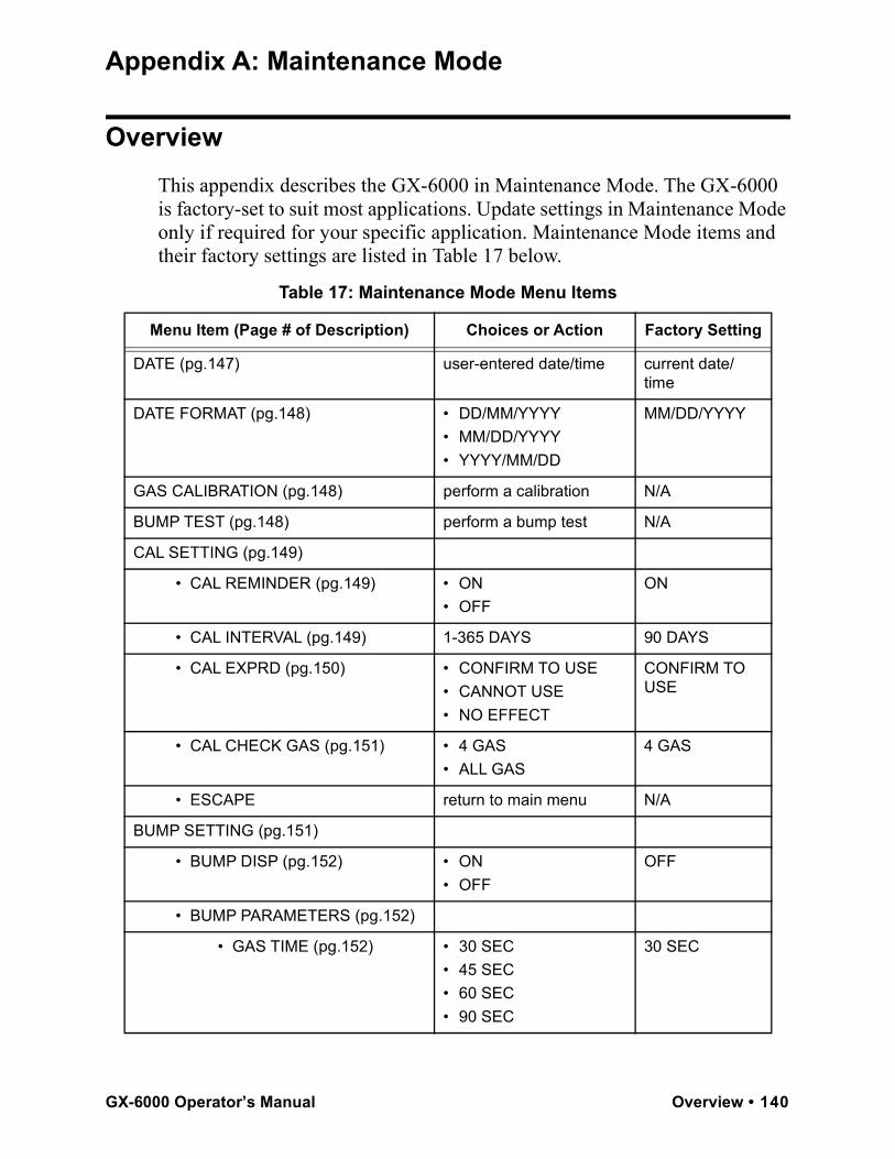
Appendix A: Maintenance Mode
OverviewThis appendix describes the GX-6000 in Maintenance Mode. The GX-6000 is factory-set to suit most applications. Update settings in Maintenance Mode only if required for your specific application. Maintenance Mode items and their factory settings are listed in Table 17 below.
Table 17: Maintenance Mode Menu Items
Menu Item (Page # of Description) Choices or Action Factory Setting
DATE (pg.147) user-entered date/time current date/time
DATE FORMAT (pg.148) • DD/MM/YYYY• MM/DD/YYYY• YYYY/MM/DD
MM/DD/YYYY
GAS CALIBRATION (pg.148) perform a calibration N/A
BUMP TEST (pg.148) perform a bump test N/A
CAL SETTING (pg.149)
• CAL REMINDER (pg.149) • ON• OFF
ON
• CAL INTERVAL (pg.149) 1-365 DAYS 90 DAYS
• CAL EXPRD (pg.150) • CONFIRM TO USE• CANNOT USE• NO EFFECT
CONFIRM TO USE
• CAL CHECK GAS (pg.151) • 4 GAS• ALL GAS
4 GAS
• ESCAPE return to main menu N/A
BUMP SETTING (pg.151)
• BUMP DISP (pg.152) • ON• OFF
OFF
• BUMP PARAMETERS (pg.152)
• GAS TIME (pg.152) • 30 SEC• 45 SEC• 60 SEC• 90 SEC
30 SEC
GX-6000 Operator’s Manual Overview • 140
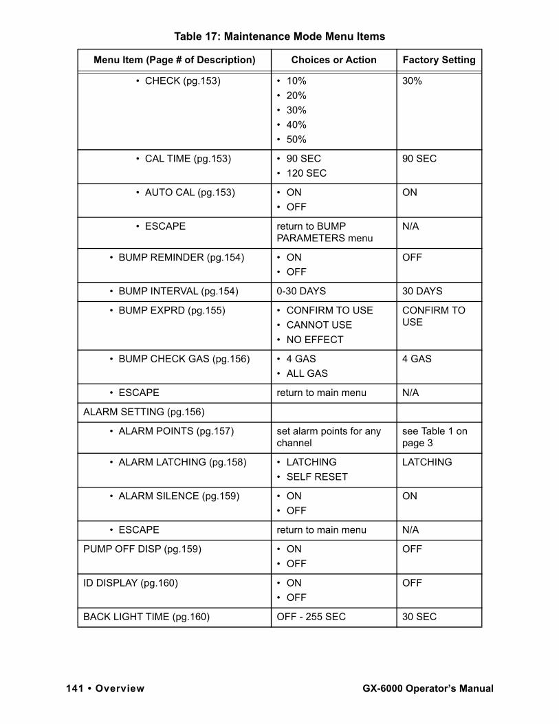
• CHECK (pg.153) • 10%• 20%• 30%• 40%• 50%
30%
• CAL TIME (pg.153) • 90 SEC• 120 SEC
90 SEC
• AUTO CAL (pg.153) • ON• OFF
ON
• ESCAPE return to BUMP PARAMETERS menu
N/A
• BUMP REMINDER (pg.154) • ON• OFF
OFF
• BUMP INTERVAL (pg.154) 0-30 DAYS 30 DAYS
• BUMP EXPRD (pg.155) • CONFIRM TO USE• CANNOT USE• NO EFFECT
CONFIRM TO USE
• BUMP CHECK GAS (pg.156) • 4 GAS• ALL GAS
4 GAS
• ESCAPE return to main menu N/A
ALARM SETTING (pg.156)
• ALARM POINTS (pg.157) set alarm points for any channel
see Table 1 on page 3
• ALARM LATCHING (pg.158) • LATCHING• SELF RESET
LATCHING
• ALARM SILENCE (pg.159) • ON• OFF
ON
• ESCAPE return to main menu N/A
PUMP OFF DISP (pg.159) • ON• OFF
OFF
ID DISPLAY (pg.160) • ON• OFF
OFF
BACK LIGHT TIME (pg.160) OFF - 255 SEC 30 SEC
Table 17: Maintenance Mode Menu Items
Menu Item (Page # of Description) Choices or Action Factory Setting
141 • Overview GX-6000 Operator’s Manual
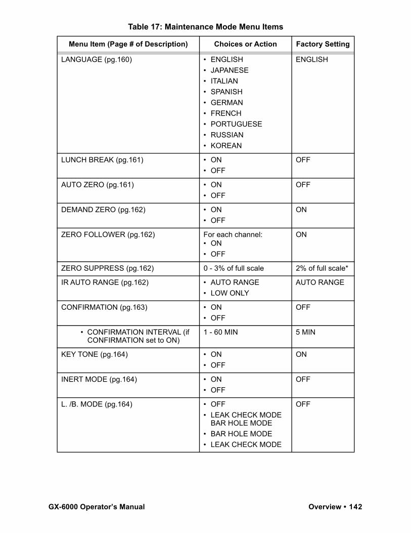
LANGUAGE (pg.160) • ENGLISH• JAPANESE• ITALIAN• SPANISH• GERMAN• FRENCH• PORTUGUESE• RUSSIAN• KOREAN
ENGLISH
LUNCH BREAK (pg.161) • ON• OFF
OFF
AUTO ZERO (pg.161) • ON• OFF
OFF
DEMAND ZERO (pg.162) • ON• OFF
ON
ZERO FOLLOWER (pg.162) For each channel:• ON• OFF
ON
ZERO SUPPRESS (pg.162) 0 - 3% of full scale 2% of full scale*
IR AUTO RANGE (pg.162) • AUTO RANGE• LOW ONLY
AUTO RANGE
CONFIRMATION (pg.163) • ON• OFF
OFF
• CONFIRMATION INTERVAL (if CONFIRMATION set to ON)
1 - 60 MIN 5 MIN
KEY TONE (pg.164) • ON• OFF
ON
INERT MODE (pg.164) • ON• OFF
OFF
L. /B. MODE (pg.164) • OFF• LEAK CHECK MODE
BAR HOLE MODE• BAR HOLE MODE• LEAK CHECK MODE
OFF
Table 17: Maintenance Mode Menu Items
Menu Item (Page # of Description) Choices or Action Factory Setting
GX-6000 Operator’s Manual Overview • 142
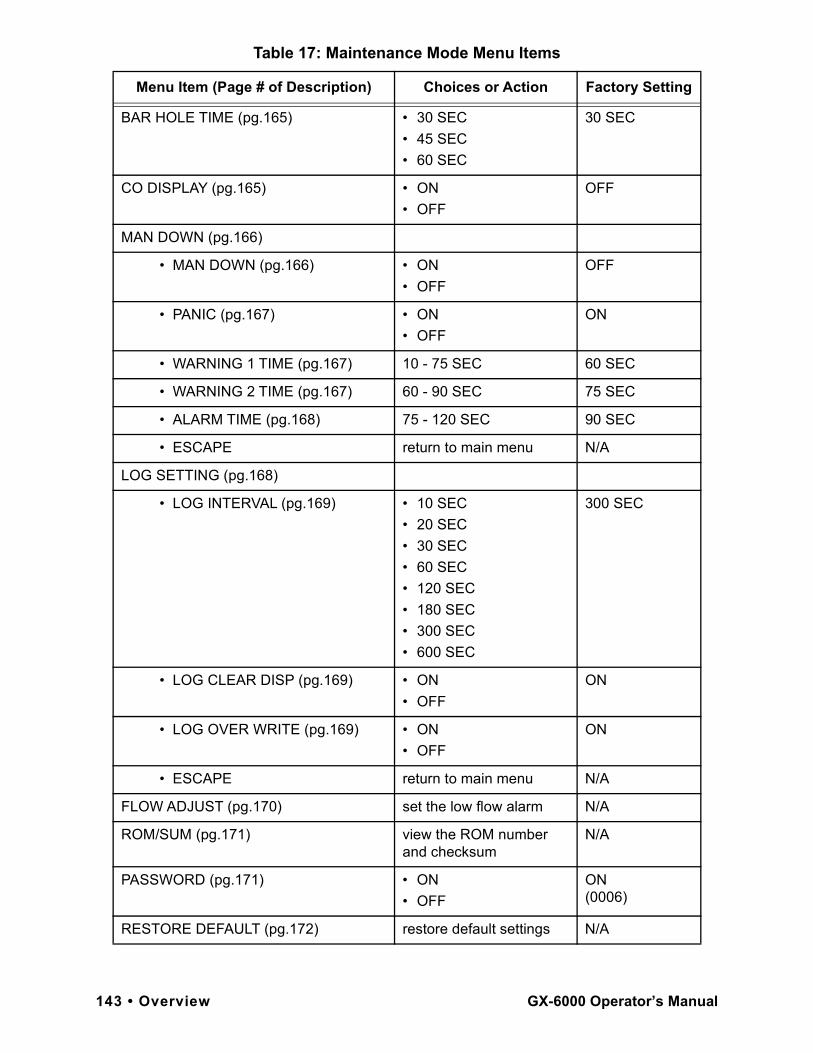
BAR HOLE TIME (pg.165) • 30 SEC• 45 SEC• 60 SEC
30 SEC
CO DISPLAY (pg.165) • ON• OFF
OFF
MAN DOWN (pg.166)
• MAN DOWN (pg.166) • ON• OFF
OFF
• PANIC (pg.167) • ON• OFF
ON
• WARNING 1 TIME (pg.167) 10 - 75 SEC 60 SEC
• WARNING 2 TIME (pg.167) 60 - 90 SEC 75 SEC
• ALARM TIME (pg.168) 75 - 120 SEC 90 SEC
• ESCAPE return to main menu N/A
LOG SETTING (pg.168)
• LOG INTERVAL (pg.169) • 10 SEC• 20 SEC• 30 SEC• 60 SEC• 120 SEC• 180 SEC• 300 SEC• 600 SEC
300 SEC
• LOG CLEAR DISP (pg.169) • ON• OFF
ON
• LOG OVER WRITE (pg.169) • ON• OFF
ON
• ESCAPE return to main menu N/A
FLOW ADJUST (pg.170) set the low flow alarm N/A
ROM/SUM (pg.171) view the ROM number and checksum
N/A
PASSWORD (pg.171) • ON• OFF
ON(0006)
RESTORE DEFAULT (pg.172) restore default settings N/A
Table 17: Maintenance Mode Menu Items
Menu Item (Page # of Description) Choices or Action Factory Setting
143 • Overview GX-6000 Operator’s Manual
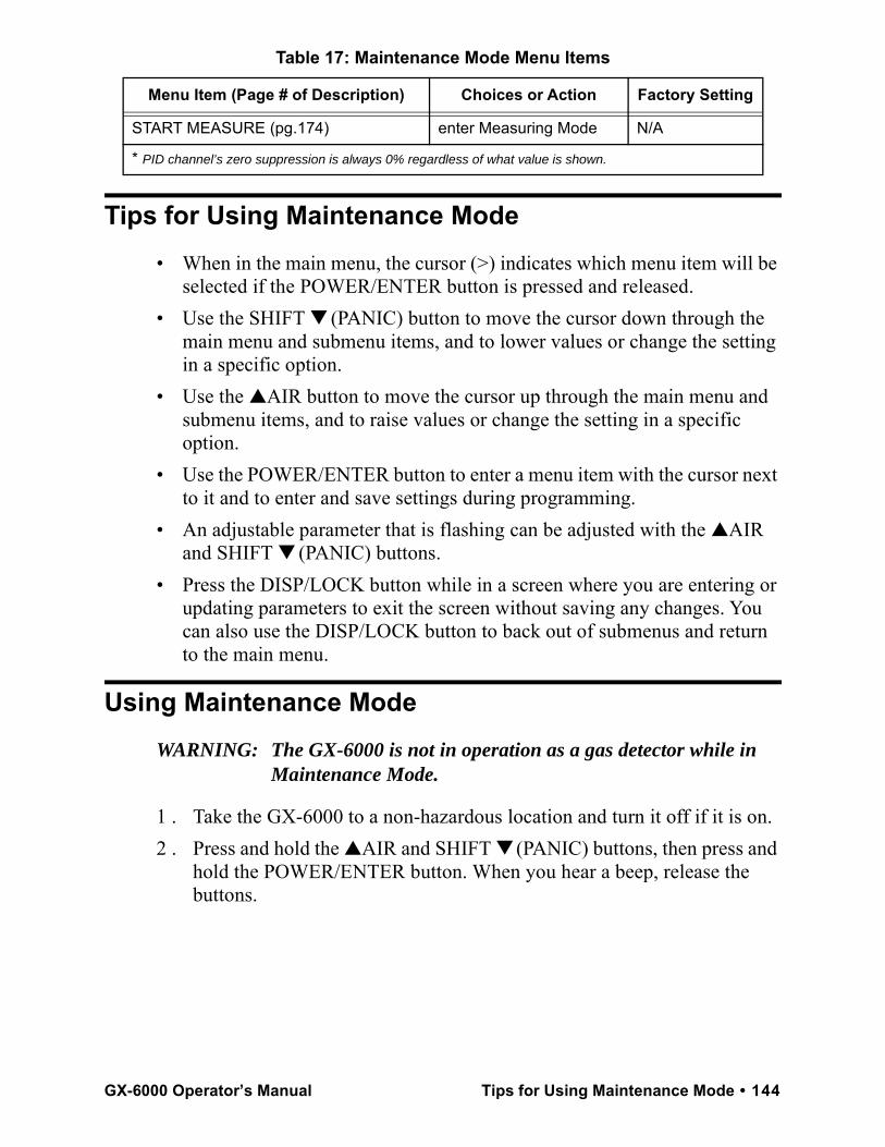
Tips for Using Maintenance Mode• When in the main menu, the cursor (>) indicates which menu item will be
selected if the POWER/ENTER button is pressed and released.• Use the SHIFT ▼ (PANIC) button to move the cursor down through the
main menu and submenu items, and to lower values or change the setting in a specific option.
• Use the ▲AIR button to move the cursor up through the main menu and submenu items, and to raise values or change the setting in a specific option.
• Use the POWER/ENTER button to enter a menu item with the cursor next to it and to enter and save settings during programming.
• An adjustable parameter that is flashing can be adjusted with the ▲AIR and SHIFT ▼ (PANIC) buttons.
• Press the DISP/LOCK button while in a screen where you are entering or updating parameters to exit the screen without saving any changes. You can also use the DISP/LOCK button to back out of submenus and return to the main menu.
Using Maintenance ModeWARNING: The GX-6000 is not in operation as a gas detector while in
Maintenance Mode.
1 . Take the GX-6000 to a non-hazardous location and turn it off if it is on.2 . Press and hold the ▲AIR and SHIFT ▼ (PANIC) buttons, then press and
hold the POWER/ENTER button. When you hear a beep, release the buttons.
START MEASURE (pg.174) enter Measuring Mode N/A
* PID channel’s zero suppression is always 0% regardless of what value is shown.
Table 17: Maintenance Mode Menu Items
Menu Item (Page # of Description) Choices or Action Factory Setting
GX-6000 Operator’s Manual Tips for Using Maintenance Mode • 144
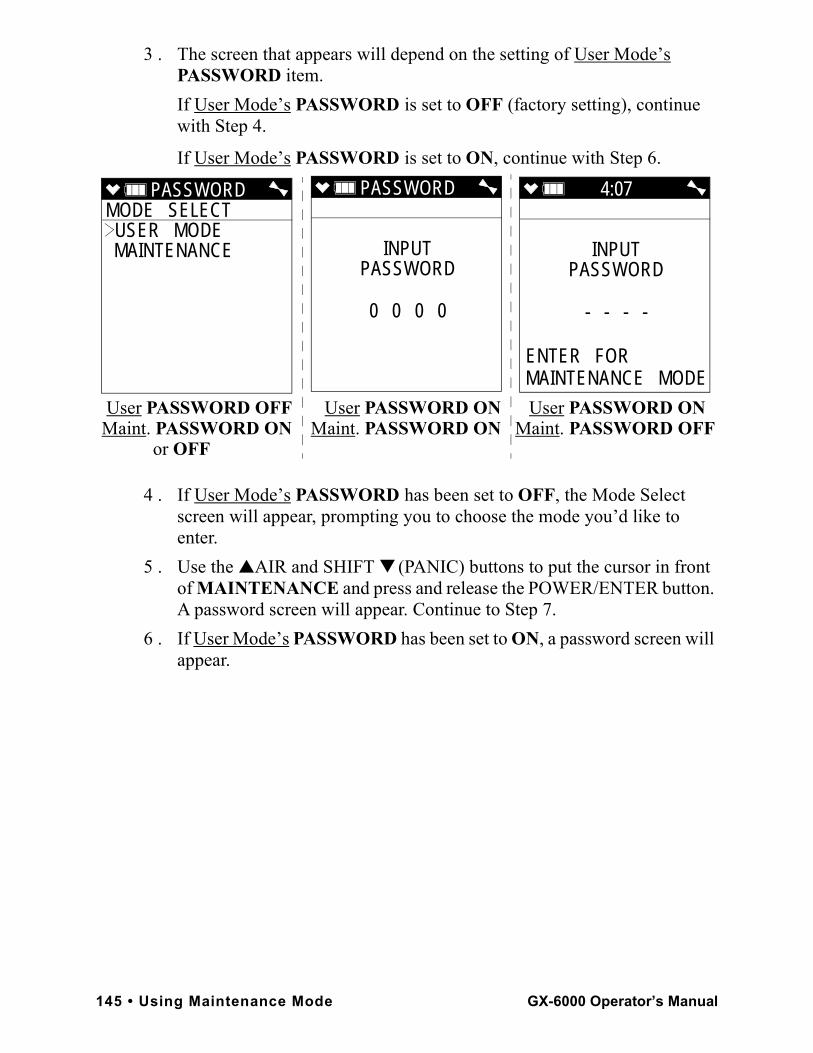
3 . The screen that appears will depend on the setting of User Mode’s PASSWORD item. If User Mode’s PASSWORD is set to OFF (factory setting), continue with Step 4.
If User Mode’s PASSWORD is set to ON, continue with Step 6.
4 . If User Mode’s PASSWORD has been set to OFF, the Mode Select screen will appear, prompting you to choose the mode you’d like to enter.
5 . Use the ▲AIR and SHIFT ▼ (PANIC) buttons to put the cursor in front of MAINTENANCE and press and release the POWER/ENTER button. A password screen will appear. Continue to Step 7.
6 . If User Mode’s PASSWORD has been set to ON, a password screen will appear.
PASSWORDMODE SELECT USER MODE MAINTENANCE
PASSWORD
INPUTPASSWORD
0 0 0 0
User PASSWORD OFF User PASSWORD ON User PASSWORD ON Maint. PASSWORD ON Maint. PASSWORD ON Maint. PASSWORD OFF or OFF
4:07
INPUTPASSWORD
- - - -
ENTER FOR MAINTENANCE MODE
145 • Using Maintenance Mode GX-6000 Operator’s Manual
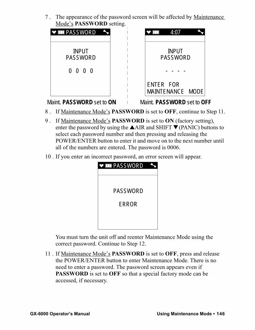
7 . The appearance of the password screen will be affected by Maintenance Mode’s PASSWORD setting.
8 . If Maintenance Mode’s PASSWORD is set to OFF, continue to Step 11.9 . If Maintenance Mode’s PASSWORD is set to ON (factory setting),
enter the password by using the ▲AIR and SHIFT ▼ (PANIC) buttons to select each password number and then pressing and releasing the POWER/ENTER button to enter it and move on to the next number until all of the numbers are entered. The password is 0006.
10 . If you enter an incorrect password, an error screen will appear.
You must turn the unit off and reenter Maintenance Mode using the correct password. Continue to Step 12.
11 . If Maintenance Mode’s PASSWORD is set to OFF, press and release the POWER/ENTER button to enter Maintenance Mode. There is no need to enter a password. The password screen appears even if PASSWORD is set to OFF so that a special factory mode can be accessed, if necessary.
PASSWORD
INPUTPASSWORD
0 0 0 0
Maint. PASSWORD set to ON Maint. PASSWORD set to OFF
4:07
INPUTPASSWORD
- - - -
ENTER FOR MAINTENANCE MODE
PASSWORD
PASSWORD
ERROR
GX-6000 Operator’s Manual Using Maintenance Mode • 146
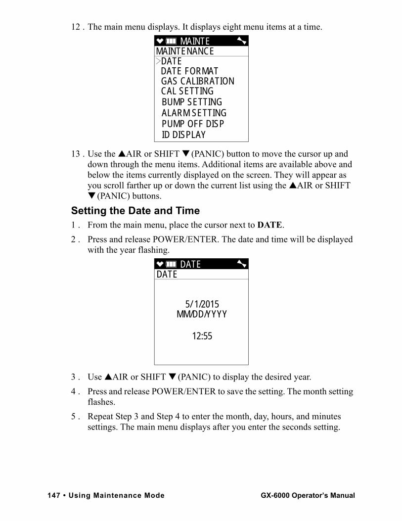
12 . The main menu displays. It displays eight menu items at a time.
13 . Use the ▲AIR or SHIFT ▼ (PANIC) button to move the cursor up and down through the menu items. Additional items are available above and below the items currently displayed on the screen. They will appear as you scroll farther up or down the current list using the ▲AIR or SHIFT ▼ (PANIC) buttons.
Setting the Date and Time1 . From the main menu, place the cursor next to DATE.2 . Press and release POWER/ENTER. The date and time will be displayed
with the year flashing.
3 . Use ▲AIR or SHIFT ▼ (PANIC) to display the desired year.4 . Press and release POWER/ENTER to save the setting. The month setting
flashes.5 . Repeat Step 3 and Step 4 to enter the month, day, hours, and minutes
settings. The main menu displays after you enter the seconds setting.
MAINTE MAINTENANCE
DATE DATE FORMAT GAS CALIBRATION CAL SETTING BUMP SETTING ALARM SETTING PUMP OFF DISP ID DISPLAY
DATE DATE
5/ 1/2015MM/DD/YYYY
12:55
147 • Using Maintenance Mode GX-6000 Operator’s Manual
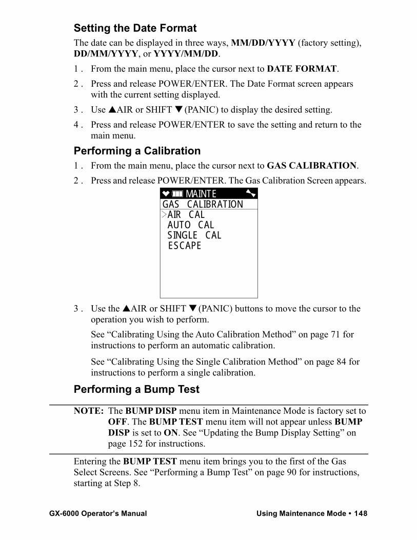
Setting the Date FormatThe date can be displayed in three ways, MM/DD/YYYY (factory setting), DD/MM/YYYY, or YYYY/MM/DD.1 . From the main menu, place the cursor next to DATE FORMAT.2 . Press and release POWER/ENTER. The Date Format screen appears
with the current setting displayed.3 . Use ▲AIR or SHIFT ▼ (PANIC) to display the desired setting.4 . Press and release POWER/ENTER to save the setting and return to the
main menu.Performing a Calibration1 . From the main menu, place the cursor next to GAS CALIBRATION.2 . Press and release POWER/ENTER. The Gas Calibration Screen appears.
3 . Use the ▲AIR or SHIFT ▼ (PANIC) buttons to move the cursor to the operation you wish to perform. See “Calibrating Using the Auto Calibration Method” on page 71 for instructions to perform an automatic calibration.
See “Calibrating Using the Single Calibration Method” on page 84 for instructions to perform a single calibration.
Performing a Bump Test
NOTE: The BUMP DISP menu item in Maintenance Mode is factory set to OFF. The BUMP TEST menu item will not appear unless BUMP DISP is set to ON. See “Updating the Bump Display Setting” on page 152 for instructions.
Entering the BUMP TEST menu item brings you to the first of the Gas Select Screens. See “Performing a Bump Test” on page 90 for instructions, starting at Step 8.
MAINTE GAS CALIBRATION
AIR CAL AUTO CAL SINGLE CAL ESCAPE
GX-6000 Operator’s Manual Using Maintenance Mode • 148

Updating Calibration SettingsThe CAL SETTING menu item in Maintenance Mode has a sub menu with 5 menu items: CAL REMINDER, CAL INTERVAL, CAL EXPRD, CAL CHECK GAS, and ESCAPE.
1 . From the main menu, place the cursor next to CAL SETTING.2 . Press and release POWER/ENTER. The CAL SETTING menu appears. Updating the Calibration Reminder SettingWith CAL REMINDER set to ON (factory setting), the GX-6000 will give an indication at start up if it is due for calibration. The type of indication will depend on the CAL EXPRD setting (see “Updating the Calibration Expired Setting” on page 150).With CAL REMINDER set to OFF, the GX-6000 will not give an indication at start up if it is due for calibration.1 . From the CAL SETTING screen, place the cursor next to CAL
REMINDER.2 . Press and release POWER/ENTER. The Calibration Reminder Screen
appears.3 . Use ▲AIR or SHIFT ▼ (PANIC) to display the desired setting.4 . Press and release POWER/ENTER to save the setting and return to the
CAL SETTING menu.Updating the Calibration IntervalThis setting defines the amount of time between calibrations. The time can be set in 1 day increments. The minimum setting is 1 day and the maximum setting is 365 days. The factory setting is 90 days.1 . From the CAL SETTING screen, place the cursor next to CAL
INTERVAL.
MAINTE CAL SETTING CAL REMINDER CAL INTERVAL CAL EXPRD CAL CHECK GAS ESCAPE
149 • Using Maintenance Mode GX-6000 Operator’s Manual
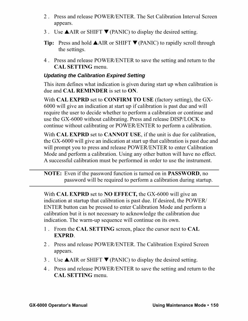
2 . Press and release POWER/ENTER. The Set Calibration Interval Screen appears.
3 . Use ▲AIR or SHIFT ▼ (PANIC) to display the desired setting.
Tip: Press and hold ▲AIR or SHIFT ▼ (PANIC) to rapidly scroll through the settings.
4 . Press and release POWER/ENTER to save the setting and return to the CAL SETTING menu.
Updating the Calibration Expired SettingThis item defines what indication is given during start up when calibration is due and CAL REMINDER is set to ON.With CAL EXPRD set to CONFIRM TO USE (factory setting), the GX-6000 will give an indication at start up if calibration is past due and will require the user to decide whether to perform a calibration or continue and use the GX-6000 without calibrating. Press and release DISP/LOCK to continue without calibrating or POWER/ENTER to perform a calibration.With CAL EXPRD set to CANNOT USE, if the unit is due for calibration, the GX-6000 will give an indication at start up that calibration is past due and will prompt you to press and release POWER/ENTER to enter Calibration Mode and perform a calibration. Using any other button will have no effect. A successful calibration must be performed in order to use the instrument.
NOTE: Even if the password function is turned on in PASSWORD, no password will be required to perform a calibration during startup.
With CAL EXPRD set to NO EFFECT, the GX-6000 will give an indication at startup that calibration is past due. If desired, the POWER/ENTER button can be pressed to enter Calibration Mode and perform a calibration but it is not necessary to acknowledge the calibration due indication. The warm-up sequence will continue on its own.1 . From the CAL SETTING screen, place the cursor next to CAL
EXPRD.2 . Press and release POWER/ENTER. The Calibration Expired Screen
appears. 3 . Use ▲AIR or SHIFT ▼ (PANIC) to display the desired setting.4 . Press and release POWER/ENTER to save the setting and return to the
CAL SETTING menu.
GX-6000 Operator’s Manual Using Maintenance Mode • 150
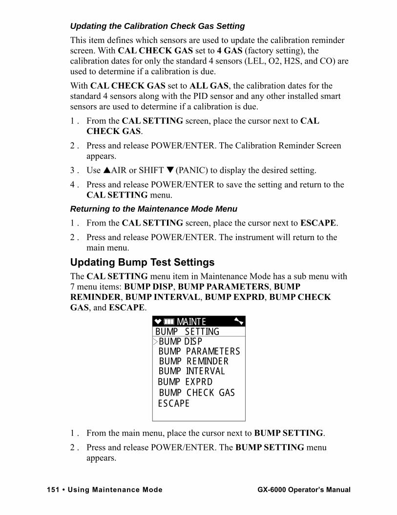
Updating the Calibration Check Gas SettingThis item defines which sensors are used to update the calibration reminder screen. With CAL CHECK GAS set to 4 GAS (factory setting), the calibration dates for only the standard 4 sensors (LEL, O2, H2S, and CO) are used to determine if a calibration is due. With CAL CHECK GAS set to ALL GAS, the calibration dates for the standard 4 sensors along with the PID sensor and any other installed smart sensors are used to determine if a calibration is due.1 . From the CAL SETTING screen, place the cursor next to CAL
CHECK GAS.2 . Press and release POWER/ENTER. The Calibration Reminder Screen
appears.3 . Use ▲AIR or SHIFT ▼ (PANIC) to display the desired setting. 4 . Press and release POWER/ENTER to save the setting and return to the
CAL SETTING menu.Returning to the Maintenance Mode Menu1 . From the CAL SETTING screen, place the cursor next to ESCAPE.2 . Press and release POWER/ENTER. The instrument will return to the
main menu.Updating Bump Test SettingsThe CAL SETTING menu item in Maintenance Mode has a sub menu with 7 menu items: BUMP DISP, BUMP PARAMETERS, BUMP REMINDER, BUMP INTERVAL, BUMP EXPRD, BUMP CHECK GAS, and ESCAPE.
1 . From the main menu, place the cursor next to BUMP SETTING.2 . Press and release POWER/ENTER. The BUMP SETTING menu
appears.
MAINTE BUMP SETTING BUMP DISP BUMP PARAMETERSBUMP REMINDER BUMP INTERVAL BUMP EXPRD
BUMP CHECK GAS ESCAPE
151 • Using Maintenance Mode GX-6000 Operator’s Manual
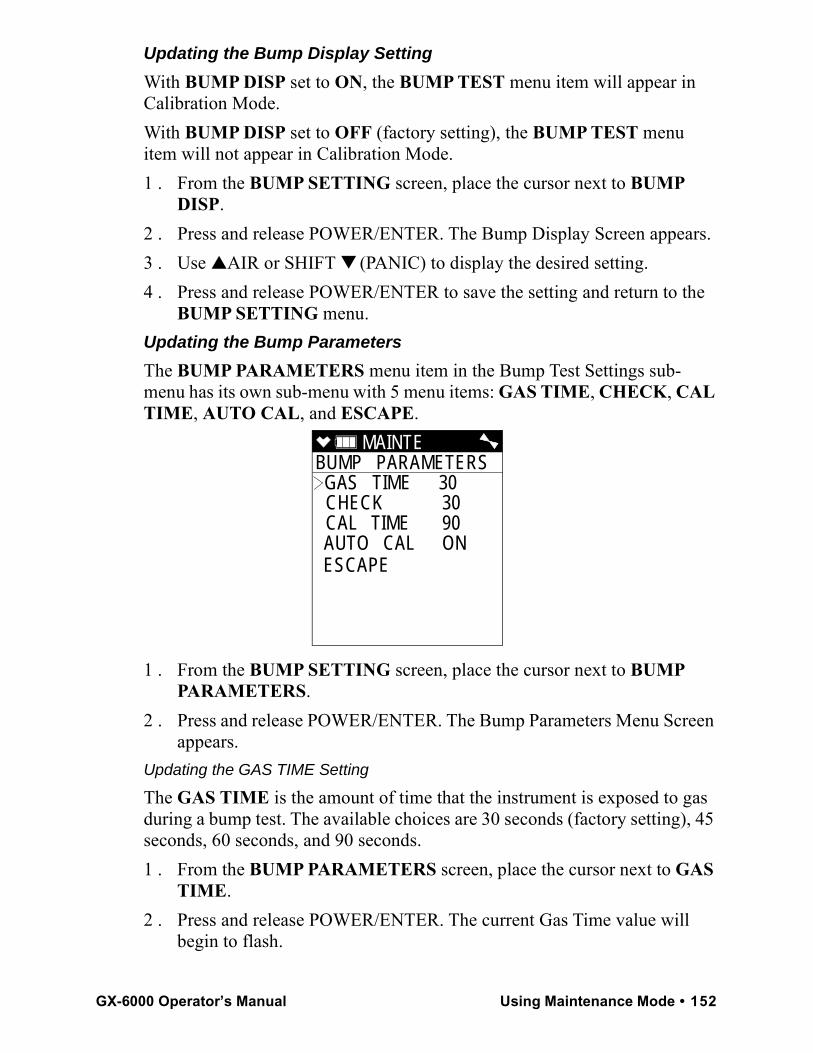
Updating the Bump Display SettingWith BUMP DISP set to ON, the BUMP TEST menu item will appear in Calibration Mode. With BUMP DISP set to OFF (factory setting), the BUMP TEST menu item will not appear in Calibration Mode. 1 . From the BUMP SETTING screen, place the cursor next to BUMP
DISP.2 . Press and release POWER/ENTER. The Bump Display Screen appears. 3 . Use ▲AIR or SHIFT ▼ (PANIC) to display the desired setting.4 . Press and release POWER/ENTER to save the setting and return to the
BUMP SETTING menu.Updating the Bump ParametersThe BUMP PARAMETERS menu item in the Bump Test Settings sub-menu has its own sub-menu with 5 menu items: GAS TIME, CHECK, CAL TIME, AUTO CAL, and ESCAPE.
1 . From the BUMP SETTING screen, place the cursor next to BUMP PARAMETERS.
2 . Press and release POWER/ENTER. The Bump Parameters Menu Screen appears.
Updating the GAS TIME Setting
The GAS TIME is the amount of time that the instrument is exposed to gas during a bump test. The available choices are 30 seconds (factory setting), 45 seconds, 60 seconds, and 90 seconds.1 . From the BUMP PARAMETERS screen, place the cursor next to GAS
TIME.2 . Press and release POWER/ENTER. The current Gas Time value will
begin to flash.
MAINTE BUMP PARAMETERS
GAS TIME 30 CHECK 30 CAL TIME 90 AUTO CAL ON ESCAPE
GX-6000 Operator’s Manual Using Maintenance Mode • 152
3 . Use ▲AIR or SHIFT ▼ (PANIC) to display the desired setting.4 . Press and release POWER/ENTER to save the setting. The value will
stop flashing.Updating the CHECK Setting
The CHECK is the bump test tolerance value and is represented as a percentage. It is the percentage that the bump test reading can differ from the actual gas concentration. If the bump test reading differs more, the bump test will fail. The available values are 10%, 20% 30% (factory setting), 40%, and 50%.1 . From the BUMP PARAMETERS screen, place the cursor next to
CHECK.2 . Press and release POWER/ENTER. The current Check value will begin
to flash. 3 . Use ▲AIR or SHIFT ▼ (PANIC) to display the desired setting.4 . Press and release POWER/ENTER to save the setting. The value will
stop flashing.Updating the CAL TIME Setting
The CAL TIME is the total time the instrument is exposed to calibration gas when a bump test fails if AUTO CAL is set to ON. The bump test time is deducted from the calibration time. For example, if the CAL TIME is set to 90 seconds and the GAS TIME is set to 30 seconds, if the bump test fails, the GX-6000 will only be exposed to gas for an additional 60 seconds. The available values are 90 seconds (factory setting), and 120 seconds.1 . From the BUMP PARAMETERS screen, place the cursor next to CAL
TIME.2 . Press and release POWER/ENTER. The current Cal Time value will
begin to flash. 3 . Use ▲AIR or SHIFT ▼ (PANIC) to display the desired setting.4 . Press and release POWER/ENTER to save the setting. The value will
stop flashing.Updating the AUTO CAL Setting
With AUTO CAL set to ON (factory setting), if a bump test fails, the unit will automatically begin a calibration. If AUTO CAL is set to OFF and a bump test fails, nothing will happen.1 . From the BUMP PARAMETERS screen, place the cursor next to
AUTO CAL.
153 • Using Maintenance Mode GX-6000 Operator’s Manual
2 . Press and release POWER/ENTER. The current Auto Cal setting will begin to flash.
3 . Use ▲AIR or SHIFT ▼ (PANIC) to display the desired setting.4 . Press and release POWER/ENTER to save the setting. The setting will
stop flashing.Returning to the BUMP SETTINGS Menu
1 . From the BUMP PARAMETERS screen, place the cursor next to ESCAPE.
2 . Press and release POWER/ENTER. The instrument will return to the BUMP SETTING screen.
Updating the Bump Reminder SettingWith BUMP REMINDER set to ON, the GX-6000 will give an indication at start up if it is due for bump testing. The type of indication will depend on the BUMP EXPRD setting (see “Updating the Bump Expired Setting” on page 155).
NOTE: If BUMP REMINDER is set to ON but BUMP DISP is set to OFF, the instrument will alert you if a bump test is due but the bump test item will not appear in Calibration Mode.
With BUMP REMINDER set to OFF (factory setting), the GX-6000 will not give an indication at start up if it is due for bump testing. 1 . From the BUMP SETTING screen, place the cursor next to BUMP
REMINDER.2 . Press and release POWER/ENTER. The current Bump Reminder setting
will be displayed. 3 . Use ▲AIR or SHIFT ▼ (PANIC) to display the desired setting.4 . Press and release POWER/ENTER to save the setting. The instrument
will return to the BUMP SETTING screen.Updating the Bump IntervalThis setting defines the amount of time between bump tests. The time can be set in 1 day increments. The minimum setting is 0 days and the maximum setting is 30 days. The factory setting is 30 days. 1 . From the BUMP SETTING screen, place the cursor next to BUMP
INTERVAL.2 . Press and release POWER/ENTER. The current Bump Interval setting
will be displayed.
GX-6000 Operator’s Manual Using Maintenance Mode • 154
3 . Use ▲AIR or SHIFT ▼ (PANIC) to display the desired setting.4 . Press and release POWER/ENTER to save the setting. The instrument
will return to the BUMP SETTING screen.Updating the Bump Expired SettingThis item defines what indication is given during start up when a bump test is due and BUMP REMINDER is set to ON.With BUMP EXPRD set to CONFIRM TO USE (factory setting), the GX-6000 will give an indication at start up if a bump test is past due and will require the user to decide whether to perform a bump test or continue and use the GX-6000 without bump testing. Press and release RESET to continue without calibrating or POWER/ENTER to enter Calibration Mode.With BUMP EXPRD set to CANNOT USE, if the unit is due for bump testing, the GX-6000 will give an indication at start up that a bump test is past due and will prompt you to press and release POWER/ENTER to enter Calibration Mode and perform a bump test. Using any other button will have no effect. A successful bump test must be performed in order to use the instrument.
NOTE: Even if the password function is turned on in PASSWORD, no password will be required to perform a bump test during startup.
NOTE: If BUMP DISP is set to OFF, the bump test menu item will not appear in Calibration Mode even though the instrument is prompting you to perform a bump test. A bump test can always be performed in Maintenance Mode, if necessary.
With BUMP EXPRD set to NO EFFECT, the GX-6000 will give an indication at startup that a bump test is past due. If desired, the POWER/ENTER button can be pressed to enter Calibration Mode and perform a bump test but it is not necessary to acknowledge the bump test due indication. The warm-up sequence will continue on its own. 1 . From the BUMP SETTING screen, place the cursor next to BUMP
EXPRD.2 . Press and release POWER/ENTER. The current Bump Expired setting
will be displayed. 3 . Use ▲AIR or SHIFT ▼ (PANIC) to display the desired setting.4 . Press and release POWER/ENTER to save the setting. The instrument
will return to the BUMP SETTING screen.
155 • Using Maintenance Mode GX-6000 Operator’s Manual
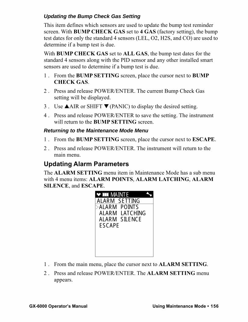
Updating the Bump Check Gas SettingThis item defines which sensors are used to update the bump test reminder screen. With BUMP CHECK GAS set to 4 GAS (factory setting), the bump test dates for only the standard 4 sensors (LEL, O2, H2S, and CO) are used to determine if a bump test is due. With BUMP CHECK GAS set to ALL GAS, the bump test dates for the standard 4 sensors along with the PID sensor and any other installed smart sensors are used to determine if a bump test is due. 1 . From the BUMP SETTING screen, place the cursor next to BUMP
CHECK GAS.2 . Press and release POWER/ENTER. The current Bump Check Gas
setting will be displayed. 3 . Use ▲AIR or SHIFT ▼ (PANIC) to display the desired setting.4 . Press and release POWER/ENTER to save the setting. The instrument
will return to the BUMP SETTING screen.Returning to the Maintenance Mode Menu1 . From the BUMP SETTING screen, place the cursor next to ESCAPE.2 . Press and release POWER/ENTER. The instrument will return to the
main menu.Updating Alarm ParametersThe ALARM SETTING menu item in Maintenance Mode has a sub menu with 4 menu items: ALARM POINTS, ALARM LATCHING, ALARM SILENCE, and ESCAPE.
1 . From the main menu, place the cursor next to ALARM SETTING.2 . Press and release POWER/ENTER. The ALARM SETTING menu
appears.
MAINTE ALARM SETTING ALARM POINTS ALARM LATCHING ALARM SILENCE ESCAPE
GX-6000 Operator’s Manual Using Maintenance Mode • 156
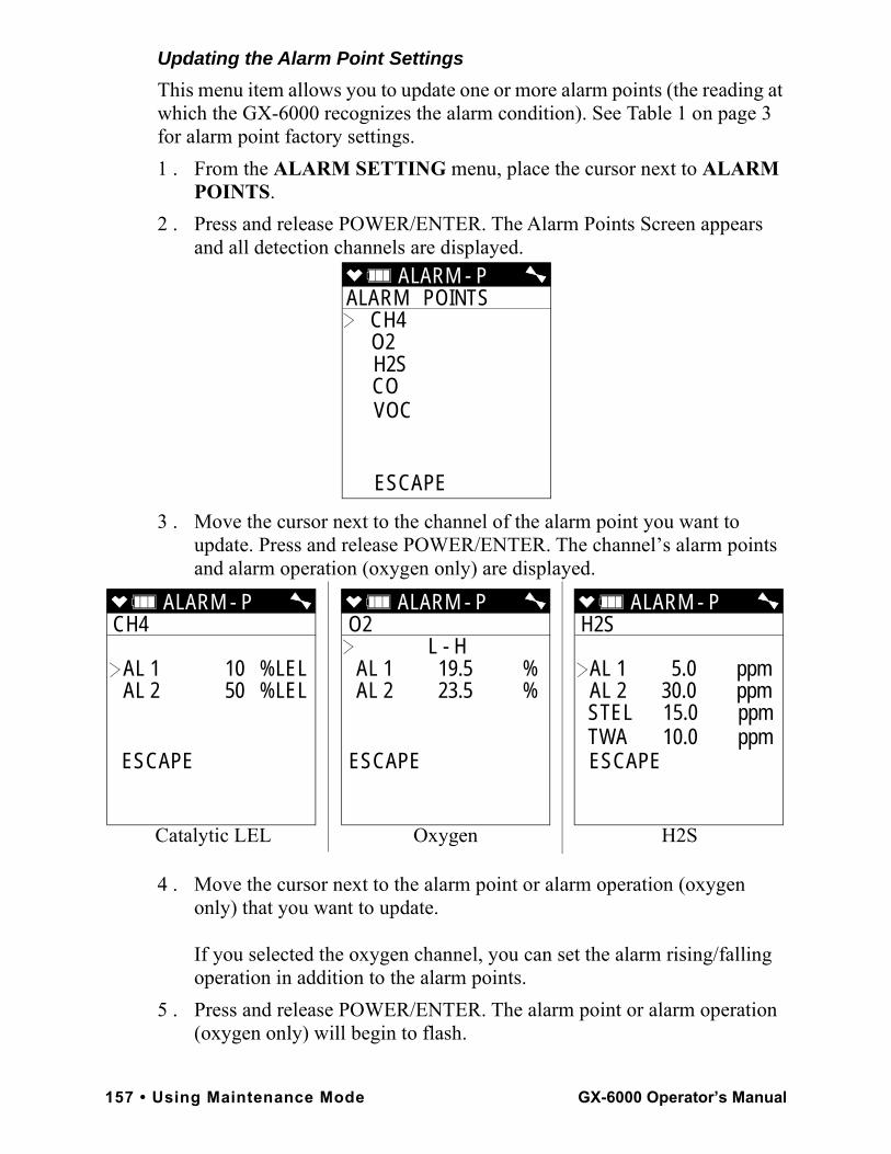
Updating the Alarm Point SettingsThis menu item allows you to update one or more alarm points (the reading at which the GX-6000 recognizes the alarm condition). See Table 1 on page 3 for alarm point factory settings.1 . From the ALARM SETTING menu, place the cursor next to ALARM
POINTS.2 . Press and release POWER/ENTER. The Alarm Points Screen appears
and all detection channels are displayed.
3 . Move the cursor next to the channel of the alarm point you want to update. Press and release POWER/ENTER. The channel’s alarm points and alarm operation (oxygen only) are displayed.
4 . Move the cursor next to the alarm point or alarm operation (oxygen only) that you want to update.
If you selected the oxygen channel, you can set the alarm rising/falling operation in addition to the alarm points.
5 . Press and release POWER/ENTER. The alarm point or alarm operation (oxygen only) will begin to flash.
ALARM - P ALARM POINTS
CH4 O2 H2S CO VOC
ESCAPE
ALARM - P CH4
AL 1 10 %LEL AL 2 50 %LEL
ESCAPE
ALARM - P O2
L - HAL 1 19.5 %AL 2 23.5 %
ESCAPE
ALARM - P H2S
AL 1 5.0 ppmAL 2 30.0 ppmSTEL 15.0 ppmTWA 10.0 ppmESCAPE
Catalytic LEL Oxygen H2S
157 • Using Maintenance Mode GX-6000 Operator’s Manual
6 . Use ▲AIR and SHIFT ▼ (PANIC) to adjust the alarm point or alarm operation (oxygen only) to the desired setting. Keep the following in mind:
• Alarm 1 cannot be set higher than Alarm 2 and Alarm 2 cannot be set lower than Alarm 1.
• In addition to setting the oxygen alarm points, you can also select one of the following operation modes: Alarm 1 decreasing and Alarm 2 increasing (L-H); Alarm 1 and Alarm 2 decreasing (L-LL); Alarm 1 and Alarm 2 increasing (H-HH). The factory setting is L-H.
• For the combustible gas channel, it is not possible to set Alarm 1 or Alarm 2 higher than 60 %LEL.
• In order to appropriately set the calibration gas value during a calibration, the Alarm 1 setting must be lower than the desired calibration value.
7 . If you want to continue with the change, press and release POWER/ENTER to accept the setting.
If you want to exit this screen without saving any change to the alarms, press and release DISP/LOCK to return to the Channel Select Screen.
8 . Repeat Step 4 - Step 7 for any additional changes you want to make to the selected channel’s alarm points.
9 . When you are done making changes to the selected channel, use SHIFT ▼ (PANIC) to move the cursor next to ESCAPE and press and release the POWER/ENTER button.
10 . Repeat Step 3 - Step 9 for any changes you want to make to additional channels.
11 . When you are done making changes to all channels, use SHIFT ▼ (PANIC) to move the cursor next to ESCAPE.
12 . Press and release POWER/ENTER to return to the ALARM SETTING menu.
Updating the Alarm Latching SettingWith ALARM LATCHING set to LATCHING (factory setting), the GX-6000 remains in alarm condition until the alarm condition passes and the RESET button is pressed.With ALARM LATCHING set to SELF RESET, the GX-6000 automatically resets an alarm when the alarm condition passes.
GX-6000 Operator’s Manual Using Maintenance Mode • 158
1 . From the ALARM SETTING menu, place the cursor next to ALARM LATCHING.
2 . Press and release POWER/ENTER. The Alarm Latching Screen appears.3 . Use ▲AIR or SHIFT ▼ (PANIC) to display the desired setting.4 . Press and release POWER/ENTER to save the setting and return to the
ALARM SETTING menu.Updating the Alarm Silence SettingWith ALARM SILENCE set to ON (factory setting), pressing and releasing the RESET button silences the buzzer when the GX-6000 is in alarm. The LEDs continue to flash, the vibrator continues to pulse, and the display continues to show the alarm. If you enter Display Mode during an alarm condition, the buzzer will be silenced but the LEDs will continue to flash and the vibrator will continue to pulse. If you return to Measuring Mode and there is still an alarm condition, the LEDs will continue to flash, the vibrator will continue to pulse, and the buzzer will remain off.With ALARM SILENCE set to OFF, you cannot silence the buzzer. If you enter Display Mode during an alarm condition, the buzzer will not be silenced, the LEDs will continue to flash, and the vibrator will continue to pulse. 1 . From the ALARM SETTING menu, place the cursor next to ALARM
SILENCE.2 . Press and release POWER/ENTER. The Alarm Silence Option Screen
appears.3 . Use ▲AIR or SHIFT ▼ (PANIC) to display the desired setting.4 . Press and release POWER/ENTER to save the setting and return to the
ALARM SETTING menu.Returning to the Maintenance Mode Menu1 . From the ALARM SETTING screen, place the cursor next to
ESCAPE.2 . Press and release POWER/ENTER. The instrument will return to the
main menu.Turning the Pump On/Off Display Screen On and OffWith PUMP OFF DISP set to ON, the Pump Off Screen appears in Display Mode and the user can turn off the pump in order to conserve battery power. With PUMP OFF DISP set to OFF (factory setting), the Pump Off Screen does not appear in Display Mode and the user cannot turn the pump off.
159 • Using Maintenance Mode GX-6000 Operator’s Manual
1 . From the main menu, place the cursor next to PUMP OFF DISP.2 . Press and release POWER/ENTER. The Pump Off Display Screen
appears.3 . Use ▲AIR or SHIFT ▼ (PANIC) to display the desired setting.4 . Press and release POWER/ENTER to save the setting and return to the
main menu.Turning the User/Station ID Function On or OffWith ID DISPLAY set to ON, the User ID and Station ID Screens display during start up and in Display Mode. With ID DISPLAY set to OFF (factory setting), the User ID and Station ID Screens do not display during start up or in Display Mode.1 . From the main menu, place the cursor next to ID DISPLAY.2 . Press and release POWER/ENTER. The User and Station ID’s Screen
appears.3 . Use ▲AIR or SHIFT ▼ (PANIC) to display the desired setting.4 . Press and release POWER/ENTER to save the setting and return to the
main menu.Updating the Backlight Time SettingThis setting indicates the length of time the LCD illuminates when you press any button. The minimum setting is OFF; the maximum setting is 255 seconds. The factory setting is 30 seconds.1 . From the main menu, place the cursor next to BACK LIGHT TIME.2 . Press and release POWER/ENTER. The Back Light Time Screen
appears.3 . Use ▲AIR and SHIFT ▼ (PANIC) to adjust the time to the desired
setting.4 . Press and release POWER/ENTER to save the setting and return to the
main menu.Updating the Language SettingThis setting allows you to select the language for the GX-6000’s user interface. The available choices are English (factory setting), Japanese, Italian, Spanish, German, French, Portuguese, Russian, and Korean.1 . From the main menu, place the cursor next to LANGUAGE.2 . Press and release POWER/ENTER. The Select Language Screen
appears with the cursor in front of the current language.
GX-6000 Operator’s Manual Using Maintenance Mode • 160
3 . Use ▲AIR or SHIFT ▼ (PANIC) to move the cursor in front of the desired language.
If you do not wish to select a new language, press and release DISP/LOCK. The unit will return to the main menu.
4 . Press and release POWER/ENTER to save the new language setting and return to the main menu. The GX-6000’s user interface will now be in the newly selected language.
5 . If you select a language other than English, a prompt will appear during startup that allows you to change the language back to English if desired.
Updating the Lunch Break SettingWith LUNCH BREAK set to OFF (factory setting), the GX-6000 automatically starts new TWA and PEAK reading collection and resets the time in operation at startup.With LUNCH BREAK set to ON, the Lunch Break Screen displays during startup. From this screen, you can choose to continue accumulating TWA and PEAK readings and the time in operation from the last time the GX-6000 was used or start collecting new readings and reset the time in operation.1 . From the main menu, place the cursor next to LUNCH BREAK.2 . Press and release POWER/ENTER. The Lunch Break Screen appears. 3 . Use ▲AIR or SHIFT ▼ (PANIC) to display the desired setting.4 . Press and release POWER/ENTER to save the setting and return to the
main menu.Updating the Auto Zero SettingThis setting allows you to configure the GX-6000 so that a fresh air adjustment takes place automatically as part of the instrument startup sequence. If AUTO ZERO is set to ON, the GX-6000 performs a fresh air adjustment at the end of the startup sequence before entering Measuring Mode. The factory setting is OFF.
WARNING: If the automatic fresh air feature is turned on, you must startup the GX-6000 in a known fresh air environment, an environment free of toxic or combustible gases and of normal oxygen content (20.9%). If this feature is on and the GX-6000 is started up in the presence of a target gas, the readings and alarms will not be accurate or reliable.
1 . From the main menu, place the cursor next to AUTO ZERO.
161 • Using Maintenance Mode GX-6000 Operator’s Manual
2 . Press and release POWER/ENTER. The Fresh Air Adjust Screen appears.
3 . Use ▲AIR or SHIFT ▼ (PANIC) to display the desired setting.4 . Press and release POWER/ENTER to save the setting and return to the
main menu.Updating the Demand Zero SettingWith DEMAND ZERO set to ON (factory setting), you can manually perform a fresh air adjust in Measuring Mode by pressing the ▲ AIR button. With DEMAND ZERO set to OFF, you cannot manually perform a fresh air adjust in Measuring Mode. 1 . From the main menu, place the cursor next to DEMAND ZERO.2 . Press and release POWER/ENTER. The Demand Zero Screen appears.3 . Use ▲AIR or SHIFT ▼ (PANIC) to display the desired setting.4 . Press and release POWER/ENTER to save the setting and return to the
main menu.Zero Follower SettingsThe ZERO FOLLOWER setting is not intended for field adjustment. The default setting for most target gases is ON. The default setting for carbon dioxide channels and some configurations of non-standard toxic gas channels is OFF. The oxygen channel does not support this feature.Zero Suppression SettingsThe ZERO SUPPRESS setting is not intended for field adjustment. The typical setting is 2% of full scale. The oxygen channel does not support this feature.Updating the Autoranging Setting
NOTE: Although IR AUTO RANGE always appears in Maintenance Mode, it only has an effect on instrument operation when an IR sensor is installed.
With IR AUTO RANGE set to AUTO RANGE (factory setting), the IR channel’s gas reading will be displayed in %LEL until the gas level reaches 100 %LEL, or 5.0 %vol for methane. Once the gas reading is above 100 %LEL, it is displayed in %vol. Alarm points exist for the %LEL range but do not exist for the %vol range.If IR AUTO RANGE is set to LOW ONLY, the IR channel’s gas reading will only be displayed in %LEL up to 100 %LEL.
GX-6000 Operator’s Manual Using Maintenance Mode • 162
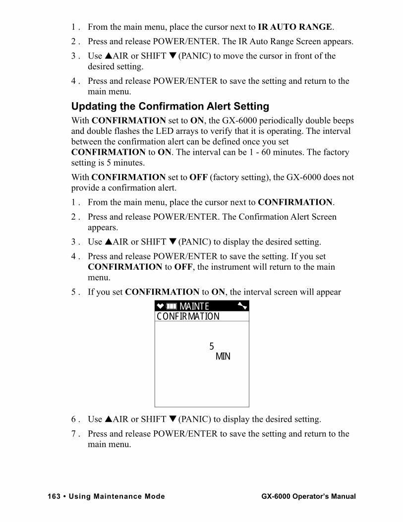
1 . From the main menu, place the cursor next to IR AUTO RANGE.2 . Press and release POWER/ENTER. The IR Auto Range Screen appears. 3 . Use ▲AIR or SHIFT ▼ (PANIC) to move the cursor in front of the
desired setting.4 . Press and release POWER/ENTER to save the setting and return to the
main menu. Updating the Confirmation Alert SettingWith CONFIRMATION set to ON, the GX-6000 periodically double beeps and double flashes the LED arrays to verify that it is operating. The interval between the confirmation alert can be defined once you set CONFIRMATION to ON. The interval can be 1 - 60 minutes. The factory setting is 5 minutes.With CONFIRMATION set to OFF (factory setting), the GX-6000 does not provide a confirmation alert.1 . From the main menu, place the cursor next to CONFIRMATION.2 . Press and release POWER/ENTER. The Confirmation Alert Screen
appears. 3 . Use ▲AIR or SHIFT ▼ (PANIC) to display the desired setting.4 . Press and release POWER/ENTER to save the setting. If you set
CONFIRMATION to OFF, the instrument will return to the main menu.
5 . If you set CONFIRMATION to ON, the interval screen will appear
6 . Use ▲AIR or SHIFT ▼ (PANIC) to display the desired setting.7 . Press and release POWER/ENTER to save the setting and return to the
main menu.
MAINTE CONFIRMATION
5 MIN
163 • Using Maintenance Mode GX-6000 Operator’s Manual
Turning the Key Tone Noise On or OffWith KEY TONE set to ON (factory setting), the instrument will beep every time a button is pressed. With KEY TONE set to OFF, the instrument will not beep when a button is pressed.1 . From the main menu, place the cursor next to KEY TONE.2 . Press and release POWER/ENTER. The Key Tone Screen appears. 3 . Use ▲AIR or SHIFT ▼ (PANIC) to display the desired setting.4 . Press and release POWER/ENTER to save the setting and return to the
main menu. Turning Inert Mode On or OffWith INERT MODE set to ON, Inert Mode becomes an option in the Mode Select Screen when the instrument turns on. Normal Mode is still an option. See “Appendix G: Using the GX-6000 in Inert Mode” on page 223 for a description of Inert Mode.With INERT MODE set to OFF (factory setting), selecting Inert Mode at startup is not an option. 1 . From the main menu, place the cursor next to INERT MODE.2 . Press and release POWER/ENTER. The Inert Mode Screen appears. 3 . Use ▲AIR or SHIFT ▼ (PANIC) to display the desired setting.4 . Press and release POWER/ENTER to save the setting and return to the
main menu. Updating the Leak Check/Bar Hole Mode SettingWith L./B. MODE set to LEAK CHECK MODE/BAR HOLE MODE, the Mode Select Screen appears when the unit is turned on. You are able to select from Normal Mode, Leak Check Mode, and Bar Hole Mode. With L./B. MODE set to BAR HOLE MODE, the Mode Select Screen appears when the unit is turned on. You are able to select from Normal Mode and Bar Hole Mode.With L./B. MODE set to LEAK CHECK MODE, the Mode Select Screen appears when the unit is turned on. You are able to select from Normal Mode and Leak Check Mode.With L./B. MODE set to OFF, the Mode Select Screen does not appear when the unit is turned on and the unit goes into Normal Mode after the start up sequence.
GX-6000 Operator’s Manual Using Maintenance Mode • 164
This setting is factory set to OFF when a unit is shipped unless the instrument is ordered for bar hole measurement or leak checking use. See and “Appendix E: Using the GX-6000 in Leak Check Mode” for a discussion of Leak Check Mode. See “Appendix F: Using the GX-6000 in Bar Hole Mode” on page 215 for a discussion of Bar Hole Mode.
NOTE: If LEAK CHECK MODE/BAR HOLE MODE or BAR HOLE MODE is selected, Bar Hole Mode will only appear as a choice in the Mode Select Screen if an IR CH4 or IR HC sensor is installed in the Smart Sensor 1 Position.
1 . From the main menu, place the cursor next to L./B. MODE.2 . Press and release POWER/ENTER. The Leak Check/Bar Hole Mode
Screen appears. 3 . Use ▲AIR or SHIFT ▼ (PANIC) to display the desired setting.4 . Press and release POWER/ENTER to save the setting and return to the
main menu.Setting the Bar Hole Measurement TimeThis setting indicates the length of time the unit will sample when a bar hole measurement is initiated in Bar Hole Mode. It can be set to 30 (factory setting), 45, or 60 seconds. 1 . From the main menu, place the cursor next to BAR HOLE TIME.2 . Press and release POWER/ENTER. The Bar Hole Measuring Time
Screen appears. 3 . Use ▲AIR or SHIFT ▼ (PANIC) to display the desired setting.4 . Press and release POWER/ENTER to save the setting and return to the
main menu.Updating the CO Display SettingWith CO DISPLAY set to OFF (factory setting), the CO channel is not displayed in Leak Check Mode. This setting has no effect on Normal Mode.With CO DISPLAY set to ON, the CO channel will be displayed in Leak Check Mode but there will be no CO alarms. If any snap logs are taken while CO DISPLAY is set to ON, the CO reading is saved but will not be displayed during the snap log and cannot be seen by viewing snap log data at the instrument. However, the CO reading(s) can be viewed using the GX-6000 Datalogging Program.1 . From the main menu, place the cursor next to CO DISPLAY.
165 • Using Maintenance Mode GX-6000 Operator’s Manual
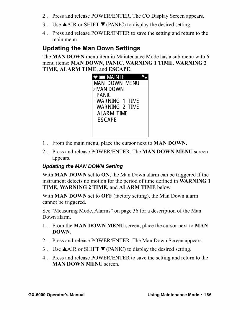
2 . Press and release POWER/ENTER. The CO Display Screen appears. 3 . Use ▲AIR or SHIFT ▼ (PANIC) to display the desired setting.4 . Press and release POWER/ENTER to save the setting and return to the
main menu. Updating the Man Down SettingsThe MAN DOWN menu item in Maintenance Mode has a sub menu with 6 menu items: MAN DOWN, PANIC, WARNING 1 TIME, WARNING 2 TIME, ALARM TIME, and ESCAPE.
1 . From the main menu, place the cursor next to MAN DOWN.2 . Press and release POWER/ENTER. The MAN DOWN MENU screen
appears. Updating the MAN DOWN SettingWith MAN DOWN set to ON, the Man Down alarm can be triggered if the instrument detects no motion for the period of time defined in WARNING 1 TIME, WARNING 2 TIME, and ALARM TIME below.With MAN DOWN set to OFF (factory setting), the Man Down alarm cannot be triggered. See “Measuring Mode, Alarms” on page 36 for a description of the Man Down alarm.1 . From the MAN DOWN MENU screen, place the cursor next to MAN
DOWN.2 . Press and release POWER/ENTER. The Man Down Screen appears. 3 . Use ▲AIR or SHIFT ▼ (PANIC) to display the desired setting.4 . Press and release POWER/ENTER to save the setting and return to the
MAN DOWN MENU screen.
MAINTE MAN DOWN MENU MAN DOWN PANIC WARNING 1 TIME WARNING 2 TIME ALARM TIME ESCAPE
GX-6000 Operator’s Manual Using Maintenance Mode • 166
Updating the PANIC SettingWith PANIC set to ON (factory setting), a Panic Alarm can be manually initiated by holding down the SHIFT ▼ (PANIC) button.With PANIC set to OFF, a Panic Alarm cannot be manually initiated. See “Measuring Mode, Alarms” on page 36 for a description of the Panic Alarm.1 . From the MAN DOWN MENU screen, place the cursor next to PANIC.2 . Press and release POWER/ENTER. The Panic Screen appears. 3 . Use ▲AIR or SHIFT ▼ (PANIC) to display the desired setting.4 . Press and release POWER/ENTER to save the setting and return to the
MAN DOWN MENU screen. Updating the WARNING 1 TIME SettingThe WARNING 1 TIME is the amount of time that has to pass between a Man Down detection and the first preliminary alarm. It can be set in 1 second increments from 10 - 120 seconds. The factory setting is 60 seconds. When setting the WARNING 1 TIME, keep in mind that ALARM TIME WARNING 2 TIME WARNING 1 TIME.1 . From the MAN DOWN MENU screen, place the cursor next to
WARNING 1 TIME.2 . Press and release POWER/ENTER. The Warning 1 Time Screen
appears. 3 . Use ▲AIR or SHIFT ▼ (PANIC) to display the desired setting.4 . Press and release POWER/ENTER to save the setting and return to the
MAN DOWN MENU screen. Updating the WARNING 2 TIME Setting The WARNING 2 TIME is the amount of time that has to pass between a Man Down detection and the second preliminary alarm. It can be set in 1 second increments from 10 - 120 seconds. The factory setting is 75 seconds. When setting the WARNING 2 TIME, keep in mind that ALARM TIME WARNING 2 TIME WARNING 1 TIME.1 . From the MAN DOWN MENU screen, place the cursor next to
WARNING 2 TIME.2 . Press and release POWER/ENTER. The Warning 2 Time Screen
appears. 3 . Use ▲AIR or SHIFT ▼ (PANIC) to display the desired setting.
167 • Using Maintenance Mode GX-6000 Operator’s Manual
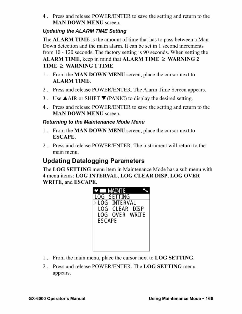
4 . Press and release POWER/ENTER to save the setting and return to the MAN DOWN MENU screen.
Updating the ALARM TIME SettingThe ALARM TIME is the amount of time that has to pass between a Man Down detection and the main alarm. It can be set in 1 second increments from 10 - 120 seconds. The factory setting is 90 seconds. When setting the ALARM TIME, keep in mind that ALARM TIME WARNING 2 TIME WARNING 1 TIME.1 . From the MAN DOWN MENU screen, place the cursor next to
ALARM TIME.2 . Press and release POWER/ENTER. The Alarm Time Screen appears. 3 . Use ▲AIR or SHIFT ▼ (PANIC) to display the desired setting.4 . Press and release POWER/ENTER to save the setting and return to the
MAN DOWN MENU screen. Returning to the Maintenance Mode Menu1 . From the MAN DOWN MENU screen, place the cursor next to
ESCAPE.2 . Press and release POWER/ENTER. The instrument will return to the
main menu.Updating Datalogging ParametersThe LOG SETTING menu item in Maintenance Mode has a sub menu with 4 menu items: LOG INTERVAL, LOG CLEAR DISP, LOG OVER WRITE, and ESCAPE.
1 . From the main menu, place the cursor next to LOG SETTING.2 . Press and release POWER/ENTER. The LOG SETTING menu
appears.
MAINTE LOG SETTING
LOG INTERVAL LOG CLEAR DISP LOG OVER WRITEESCAPE
GX-6000 Operator’s Manual Using Maintenance Mode • 168
Updating the Data Log Interval SettingThis setting indicates how often the GX-6000 saves readings to the data logger. The following interval times can be selected: 10 minutes, 5 minutes (factory setting), 3 minutes, 2 minutes, 1 minute, 30 seconds, 20 seconds, or 10 seconds. 1 . From the LOG SETTING screen, place the cursor next to LOG
INTERVAL.2 . Press and release POWER/ENTER. The Log Interval Screen appears. 3 . Use ▲AIR or SHIFT ▼ (PANIC) to display the desired setting.4 . Press and release POWER/ENTER to save the setting and return to the
LOG SETTING screen. Updating the Log Clear Display SettingWith LOG CLEAR DISP set to ON (factory setting), the LOG CLEAR Screen appears in Display Mode (see “LOG CLEAR Screen” on page 52).With LOG CLEAR DISP set to OFF, the LOG CLEAR Screen does not appear in Display Mode.1 . From the LOG SETTING screen, place the cursor next to LOG
CLEAR DISP.2 . Press and release POWER/ENTER. The Log Clear Display Screen
appears. 3 . Use ▲AIR or SHIFT ▼ (PANIC) to display the desired setting.4 . Press and release POWER/ENTER to save the setting and return to the
LOG SETTING screen. Updating the Data Log Overwrite SettingWith LOG OVER WRITE set to ON (factory setting), the GX-6000 writes over the oldest data with new data when the data logger memory is full.With LOG OVER WRITE set to OFF, the GX-6000 stops saving data to the data logger when the data logger memory is full.1 . From the LOG SETTING screen, place the cursor next to LOG OVER
WRITE.2 . Press and release POWER/ENTER. The Log Over Write Screen appears. 3 . Use ▲AIR or SHIFT ▼ (PANIC) to display the desired setting.4 . Press and release POWER/ENTER to save the setting and return to the
LOG SETTING screen.
169 • Using Maintenance Mode GX-6000 Operator’s Manual
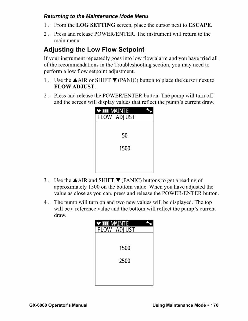
Returning to the Maintenance Mode Menu1 . From the LOG SETTING screen, place the cursor next to ESCAPE.2 . Press and release POWER/ENTER. The instrument will return to the
main menu.Adjusting the Low Flow SetpointIf your instrument repeatedly goes into low flow alarm and you have tried all of the recommendations in the Troubleshooting section, you may need to perform a low flow setpoint adjustment. 1 . Use the ▲AIR or SHIFT ▼ (PANIC) button to place the cursor next to
FLOW ADJUST.2 . Press and release the POWER/ENTER button. The pump will turn off
and the screen will display values that reflect the pump’s current draw.
3 . Use the ▲AIR and SHIFT ▼ (PANIC) buttons to get a reading of approximately 1500 on the bottom value. When you have adjusted the value as close as you can, press and release the POWER/ENTER button.
4 . The pump will turn on and two new values will be displayed. The top will be a reference value and the bottom will reflect the pump’s current draw.
MAINTE FLOW ADJUST
50
1500
MAINTE FLOW ADJUST
1500
2500
GX-6000 Operator’s Manual Using Maintenance Mode • 170
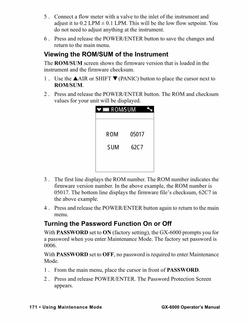
5 . Connect a flow meter with a valve to the inlet of the instrument and adjust it to 0.2 LPM ± 0.1 LPM. This will be the low flow setpoint. You do not need to adjust anything at the instrument.
6 . Press and release the POWER/ENTER button to save the changes and return to the main menu.
Viewing the ROM/SUM of the InstrumentThe ROM/SUM screen shows the firmware version that is loaded in the instrument and the firmware checksum. 1 . Use the ▲AIR or SHIFT ▼ (PANIC) button to place the cursor next to
ROM/SUM. 2 . Press and release the POWER/ENTER button. The ROM and checksum
values for your unit will be displayed.
3 . The first line displays the ROM number. The ROM number indicates the firmware version number. In the above example, the ROM number is 05017. The bottom line displays the firmware file’s checksum, 62C7 in the above example.
4 . Press and release the POWER/ENTER button again to return to the main menu.
Turning the Password Function On or OffWith PASSWORD set to ON (factory setting), the GX-6000 prompts you for a password when you enter Maintenance Mode. The factory set password is 0006.With PASSWORD set to OFF, no password is required to enter Maintenance Mode.1 . From the main menu, place the cursor in front of PASSWORD.2 . Press and release POWER/ENTER. The Password Protection Screen
appears.
ROM/SUM
ROM 05017
SUM 62C7
171 • Using Maintenance Mode GX-6000 Operator’s Manual
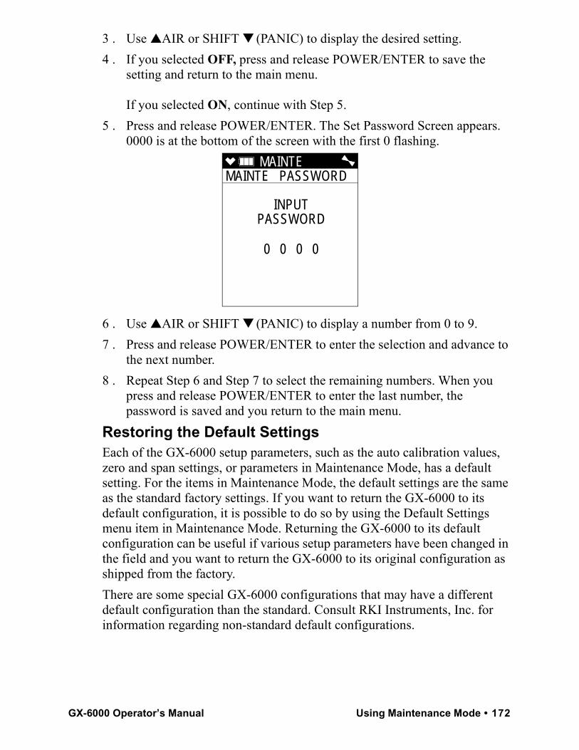
3 . Use ▲AIR or SHIFT ▼ (PANIC) to display the desired setting.4 . If you selected OFF, press and release POWER/ENTER to save the
setting and return to the main menu.
If you selected ON, continue with Step 5.5 . Press and release POWER/ENTER. The Set Password Screen appears.
0000 is at the bottom of the screen with the first 0 flashing.
6 . Use ▲AIR or SHIFT ▼ (PANIC) to display a number from 0 to 9.7 . Press and release POWER/ENTER to enter the selection and advance to
the next number.8 . Repeat Step 6 and Step 7 to select the remaining numbers. When you
press and release POWER/ENTER to enter the last number, the password is saved and you return to the main menu.
Restoring the Default SettingsEach of the GX-6000 setup parameters, such as the auto calibration values, zero and span settings, or parameters in Maintenance Mode, has a default setting. For the items in Maintenance Mode, the default settings are the same as the standard factory settings. If you want to return the GX-6000 to its default configuration, it is possible to do so by using the Default Settings menu item in Maintenance Mode. Returning the GX-6000 to its default configuration can be useful if various setup parameters have been changed in the field and you want to return the GX-6000 to its original configuration as shipped from the factory.There are some special GX-6000 configurations that may have a different default configuration than the standard. Consult RKI Instruments, Inc. for information regarding non-standard default configurations.
MAINTE MAINTE PASSWORD
INPUTPASSWORD
0 0 0 0
GX-6000 Operator’s Manual Using Maintenance Mode • 172
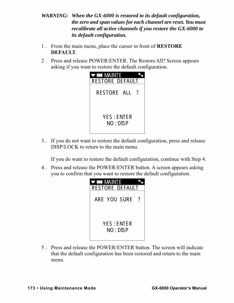
WARNING: When the GX-6000 is restored to its default configuration, the zero and span values for each channel are reset. You must recalibrate all active channels if you restore the GX-6000 to its default configuration.
1 . From the main menu, place the cursor in front of RESTORE DEFAULT.
2 . Press and release POWER/ENTER. The Restore All? Screen appears asking if you want to restore the default configuration.
3 . If you do not want to restore the default configuration, press and release DISP/LOCK to return to the main menu.
If you do want to restore the default configuration, continue with Step 4.4 . Press and release the POWER/ENTER button. A screen appears asking
you to confirm that you want to restore the default configuration.
5 . Press and release the POWER/ENTER button. The screen will indicate that the default configuration has been restored and return to the main menu.
MAINTE RESTORE DEFAULT
RESTORE ALL ?
YES : ENTERNO : DISP
MAINTE RESTORE DEFAULT
ARE YOU SURE ?
YES : ENTERNO : DISP
173 • Using Maintenance Mode GX-6000 Operator’s Manual
Exiting Maintenance Mode1 . From the main menu, place the cursor in front of START MEASURE at
the bottom of the menu.2 . Press and release POWER/ENTER.3 . The unit will begin its start-up sequence.
GX-6000 Operator’s Manual Using Maintenance Mode • 174
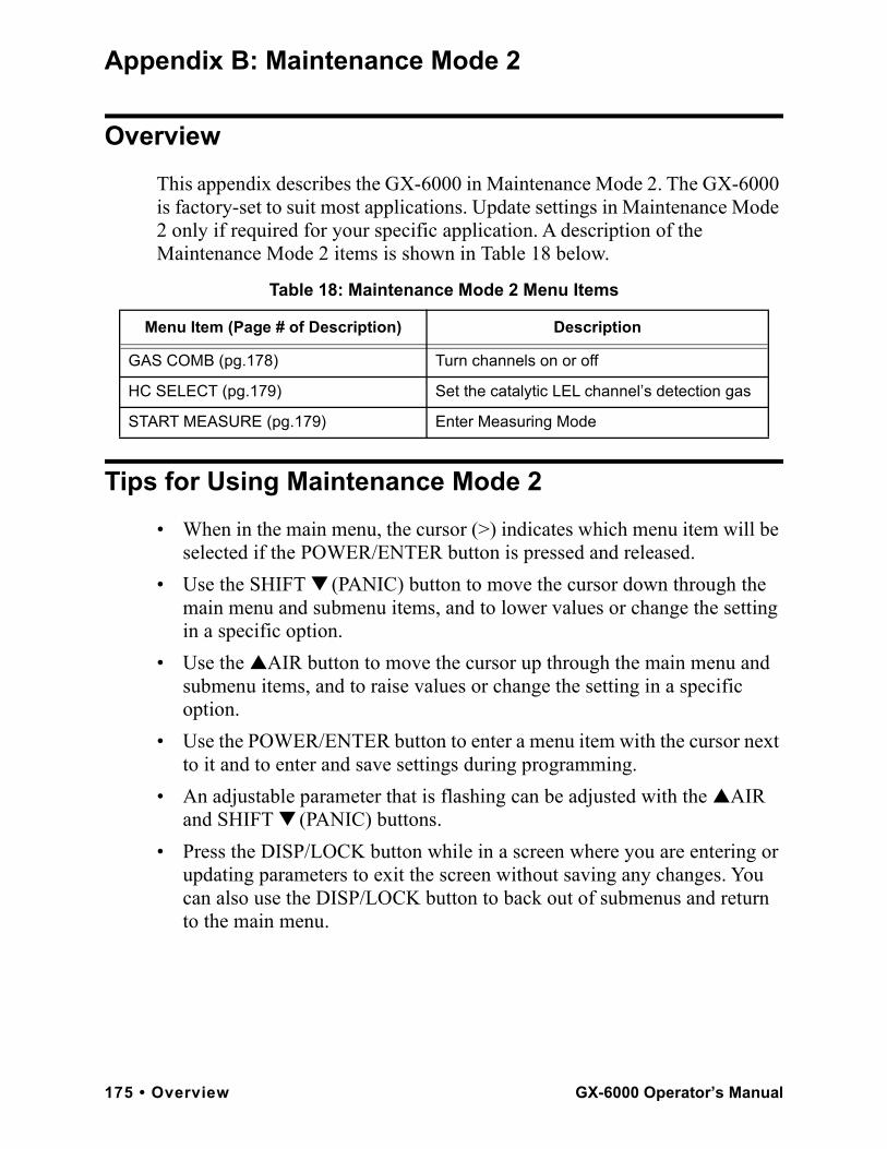
Appendix B: Maintenance Mode 2
OverviewThis appendix describes the GX-6000 in Maintenance Mode 2. The GX-6000 is factory-set to suit most applications. Update settings in Maintenance Mode 2 only if required for your specific application. A description of the Maintenance Mode 2 items is shown in Table 18 below.
Tips for Using Maintenance Mode 2• When in the main menu, the cursor (>) indicates which menu item will be
selected if the POWER/ENTER button is pressed and released.• Use the SHIFT ▼ (PANIC) button to move the cursor down through the
main menu and submenu items, and to lower values or change the setting in a specific option.
• Use the ▲AIR button to move the cursor up through the main menu and submenu items, and to raise values or change the setting in a specific option.
• Use the POWER/ENTER button to enter a menu item with the cursor next to it and to enter and save settings during programming.
• An adjustable parameter that is flashing can be adjusted with the ▲AIR and SHIFT ▼ (PANIC) buttons.
• Press the DISP/LOCK button while in a screen where you are entering or updating parameters to exit the screen without saving any changes. You can also use the DISP/LOCK button to back out of submenus and return to the main menu.
Table 18: Maintenance Mode 2 Menu Items
Menu Item (Page # of Description) Description
GAS COMB (pg.178) Turn channels on or off
HC SELECT (pg.179) Set the catalytic LEL channel’s detection gas
START MEASURE (pg.179) Enter Measuring Mode
175 • Overview GX-6000 Operator’s Manual
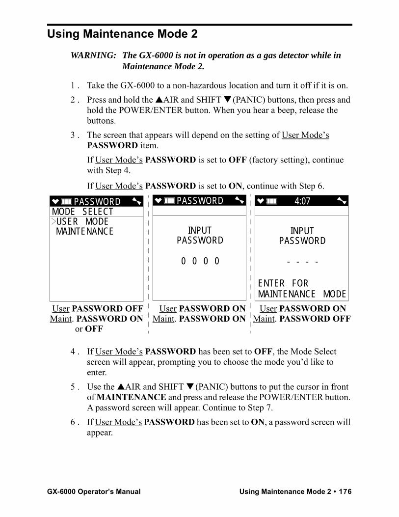
Using Maintenance Mode 2WARNING: The GX-6000 is not in operation as a gas detector while in
Maintenance Mode 2.
1 . Take the GX-6000 to a non-hazardous location and turn it off if it is on.2 . Press and hold the ▲AIR and SHIFT ▼ (PANIC) buttons, then press and
hold the POWER/ENTER button. When you hear a beep, release the buttons.
3 . The screen that appears will depend on the setting of User Mode’s PASSWORD item. If User Mode’s PASSWORD is set to OFF (factory setting), continue with Step 4.
If User Mode’s PASSWORD is set to ON, continue with Step 6.
4 . If User Mode’s PASSWORD has been set to OFF, the Mode Select screen will appear, prompting you to choose the mode you’d like to enter.
5 . Use the ▲AIR and SHIFT ▼ (PANIC) buttons to put the cursor in front of MAINTENANCE and press and release the POWER/ENTER button. A password screen will appear. Continue to Step 7.
6 . If User Mode’s PASSWORD has been set to ON, a password screen will appear.
PASSWORDMODE SELECT USER MODE MAINTENANCE
PASSWORD
INPUTPASSWORD
0 0 0 0
User PASSWORD OFF User PASSWORD ON User PASSWORD ON Maint. PASSWORD ON Maint. PASSWORD ON Maint. PASSWORD OFF or OFF
4:07
INPUTPASSWORD
- - - -
ENTER FOR MAINTENANCE MODE
GX-6000 Operator’s Manual Using Maintenance Mode 2 • 176
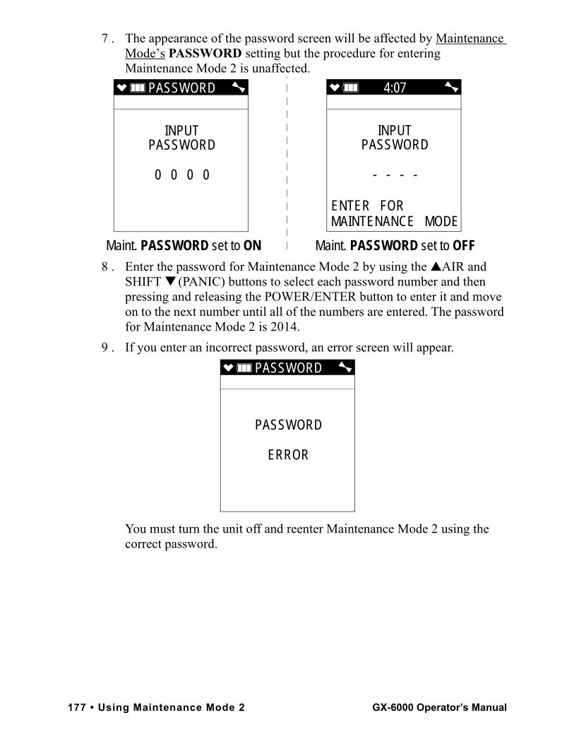
7 . The appearance of the password screen will be affected by Maintenance Mode’s PASSWORD setting but the procedure for entering Maintenance Mode 2 is unaffected.
8 . Enter the password for Maintenance Mode 2 by using the ▲AIR and SHIFT ▼ (PANIC) buttons to select each password number and then pressing and releasing the POWER/ENTER button to enter it and move on to the next number until all of the numbers are entered. The password for Maintenance Mode 2 is 2014.
9 . If you enter an incorrect password, an error screen will appear.
You must turn the unit off and reenter Maintenance Mode 2 using the correct password.
PASSWORD
INPUTPASSWORD
0 0 0 0
Maint. PASSWORD set to ON Maint. PASSWORD set to OFF
4:07
INPUTPASSWORD
- - - -
ENTER FOR MAINTENANCE MODE
PASSWORD
PASSWORD
ERROR
177 • Using Maintenance Mode 2 GX-6000 Operator’s Manual
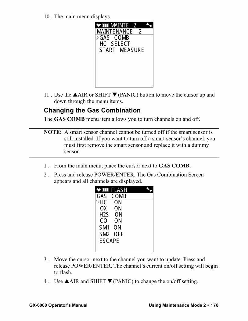
10 . The main menu displays.
11 . Use the ▲AIR or SHIFT ▼ (PANIC) button to move the cursor up and down through the menu items.
Changing the Gas CombinationThe GAS COMB menu item allows you to turn channels on and off.
NOTE: A smart sensor channel cannot be turned off if the smart sensor is still installed. If you want to turn off a smart sensor’s channel, you must first remove the smart sensor and replace it with a dummy sensor.
1 . From the main menu, place the cursor next to GAS COMB.2 . Press and release POWER/ENTER. The Gas Combination Screen
appears and all channels are displayed.
3 . Move the cursor next to the channel you want to update. Press and release POWER/ENTER. The channel’s current on/off setting will begin to flash.
4 . Use ▲AIR and SHIFT ▼ (PANIC) to change the on/off setting.
MAINTE 2 MAINTENANCE 2 GAS COMB HC SELECT START MEASURE
FLASH GAS COMB
HC ON OX ON H2S ON CO ON SM1 ON SM2 OFF ESCAPE
GX-6000 Operator’s Manual Using Maintenance Mode 2 • 178
5 . If you want to continue with the change, press and release POWER/ENTER to accept the setting.
If you want to exit this screen without saving the change, press and release DISP/LOCK to return to the main menu.
6 . Repeat Step 3 - Step 5 for any changes you want to make to additional channels.
7 . When you are done making changes to all channels, use SHIFT ▼ (PANIC) to move the cursor next to ESCAPE.
8 . Press and release POWER/ENTER to return to the main menu.Changing the Catalytic LEL Channel’s Target GasThe HC SELECT menu item allows you to change the catalytic LEL channel’s target gas. With HC SELECT set to CH4 (factory setting), the catalytic LEL channel should be calibrated to methane.With HC SELECT set to HC, the catalytic LEL channel can be calibrated to a desired combustible gas.1 . From the main menu, place the cursor next to HC SELECT.2 . Press and release POWER/ENTER. The HC Select Screen appears. 3 . Use ▲AIR or SHIFT ▼ (PANIC) to display the desired setting.4 . Press and release POWER/ENTER to save the setting and return to the
main menu. Exiting Maintenance Mode 21 . From the main menu, place the cursor in front of START MEASURE at
the bottom of the menu.2 . Press and release POWER/ENTER.3 . The unit will begin its start-up sequence.
179 • Using Maintenance Mode 2 GX-6000 Operator’s Manual
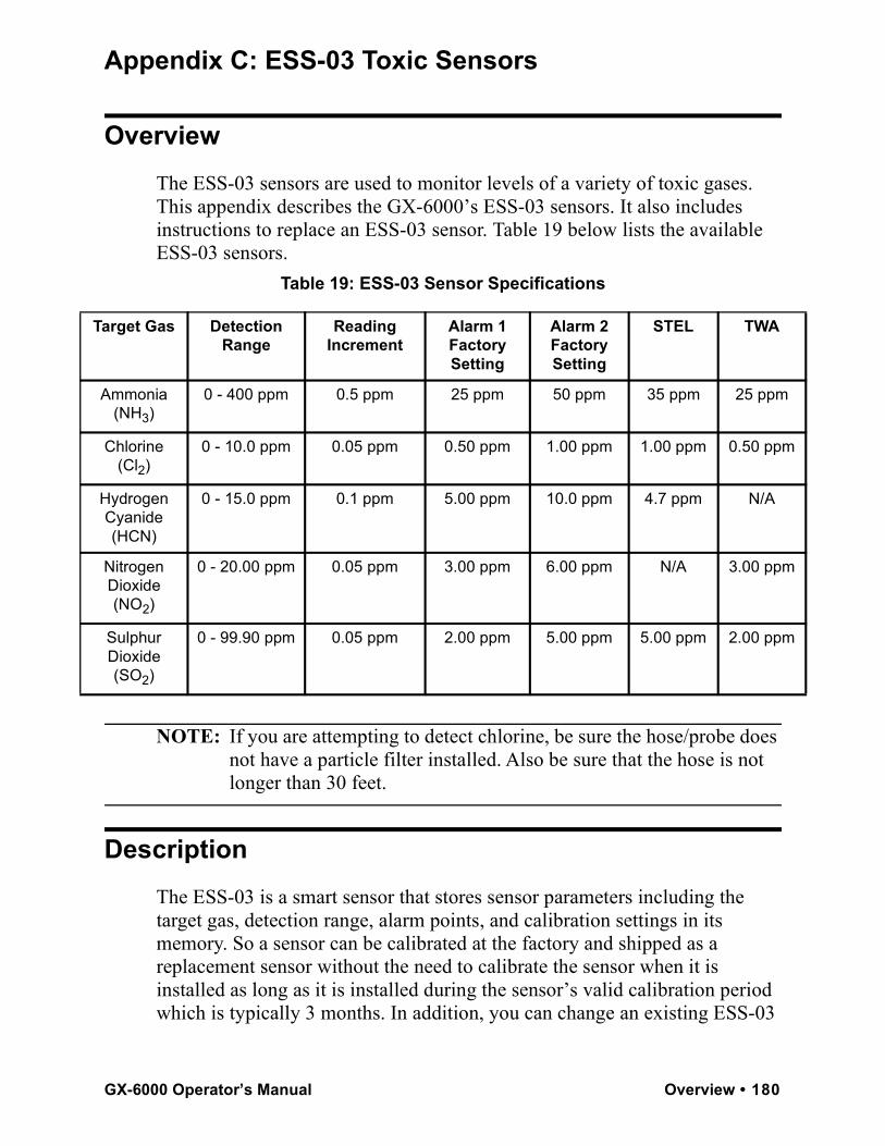
Appendix C: ESS-03 Toxic Sensors
OverviewThe ESS-03 sensors are used to monitor levels of a variety of toxic gases. This appendix describes the GX-6000’s ESS-03 sensors. It also includes instructions to replace an ESS-03 sensor. Table 19 below lists the available ESS-03 sensors.
Table 19: ESS-03 Sensor Specifications
NOTE: If you are attempting to detect chlorine, be sure the hose/probe does not have a particle filter installed. Also be sure that the hose is not longer than 30 feet.
DescriptionThe ESS-03 is a smart sensor that stores sensor parameters including the target gas, detection range, alarm points, and calibration settings in its memory. So a sensor can be calibrated at the factory and shipped as a replacement sensor without the need to calibrate the sensor when it is installed as long as it is installed during the sensor’s valid calibration period which is typically 3 months. In addition, you can change an existing ESS-03
Target Gas Detection Range
Reading Increment
Alarm 1FactorySetting
Alarm 2FactorySetting
STEL TWA
Ammonia (NH3)
0 - 400 ppm 0.5 ppm 25 ppm 50 ppm 35 ppm 25 ppm
Chlorine (Cl2)
0 - 10.0 ppm 0.05 ppm 0.50 ppm 1.00 ppm 1.00 ppm 0.50 ppm
Hydrogen Cyanide (HCN)
0 - 15.0 ppm 0.1 ppm 5.00 ppm 10.0 ppm 4.7 ppm N/A
Nitrogen Dioxide (NO2)
0 - 20.00 ppm 0.05 ppm 3.00 ppm 6.00 ppm N/A 3.00 ppm
Sulphur Dioxide (SO2)
0 - 99.90 ppm 0.05 ppm 2.00 ppm 5.00 ppm 5.00 ppm 2.00 ppm
GX-6000 Operator’s Manual Overview • 180
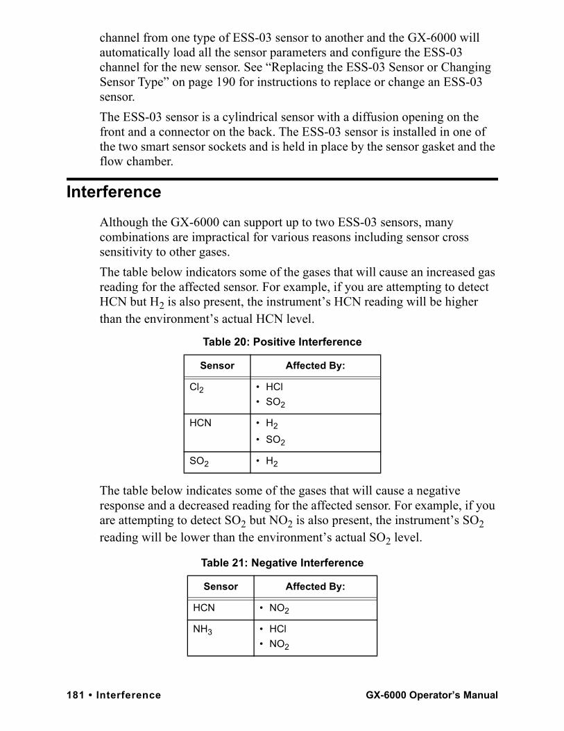
channel from one type of ESS-03 sensor to another and the GX-6000 will automatically load all the sensor parameters and configure the ESS-03 channel for the new sensor. See “Replacing the ESS-03 Sensor or Changing Sensor Type” on page 190 for instructions to replace or change an ESS-03 sensor. The ESS-03 sensor is a cylindrical sensor with a diffusion opening on the front and a connector on the back. The ESS-03 sensor is installed in one of the two smart sensor sockets and is held in place by the sensor gasket and the flow chamber.
InterferenceAlthough the GX-6000 can support up to two ESS-03 sensors, many combinations are impractical for various reasons including sensor cross sensitivity to other gases. The table below indicators some of the gases that will cause an increased gas reading for the affected sensor. For example, if you are attempting to detect HCN but H2 is also present, the instrument’s HCN reading will be higher than the environment’s actual HCN level.
The table below indicates some of the gases that will cause a negative response and a decreased reading for the affected sensor. For example, if you are attempting to detect SO2 but NO2 is also present, the instrument’s SO2 reading will be lower than the environment’s actual SO2 level.
Table 20: Positive Interference
Sensor Affected By:
Cl2 • HCl• SO2
HCN • H2
• SO2
SO2 • H2
Table 21: Negative Interference
Sensor Affected By:
HCN • NO2
NH3 • HCl• NO2
181 • Interference GX-6000 Operator’s Manual
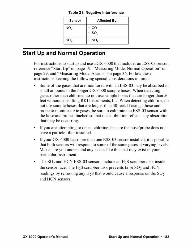
Start Up and Normal OperationFor instructions to startup and use a GX-6000 that includes an ESS-03 sensor, reference “Start Up” on page 19, “Measuring Mode, Normal Operation” on page 29, and “Measuring Mode, Alarms” on page 36. Follow these instructions keeping the following special considerations in mind:• Some of the gases that are monitored with an ESS-03 may be absorbed in
small amounts in the longer GX-6000 sample hoses. When detecting gases other than chlorine, do not use sample hoses that are longer than 50 feet without consulting RKI Instruments, Inc. When detecting chlorine, do not use sample hoses that are longer than 30 feet. If using a hose and probe to monitor toxic gases, be sure to calibrate the ESS-03 sensor with the hose and probe attached so that the calibration reflects any absorption that may be occurring.
• If you are attempting to detect chlorine, be sure the hose/probe does not have a particle filter installed.
• If your GX-6000 has more than one ESS-03 sensor installed, it is possible that both sensors will respond to some of the same gases at varying levels. Make sure you understand any issues like this that may exist in your particular instrument.
• The SO2 and HCN ESS-03 sensors include an H2S scrubber disk inside the sensor face. The H2S scrubber disk prevents false SO2 and HCN readings by removing any H2S that would cause a response on the SO2 and HCN sensors.
NO2 • CO• SO2
SO2 • NO2
Table 21: Negative Interference
Sensor Affected By:
GX-6000 Operator’s Manual Start Up and Normal Operation • 182
ESS-03 CalibrationAn ESS-03 channel can be calibrated using the auto calibration method or the single calibration method.
NOTE: ESS-03 calibration must be done with the hose and probe attached. If you are calibrating a chlorine sensor, be sure the hose/probe does not have a particle filter installed.
Calibrating the ESS-03 Sensor Using Auto CalibrationThe calibration instructions below assume a standard 4 plus PID plus ESS-03 instrument configuration. There are several ways to calibrate a standard 4 plus PID plus ESS-03 instrument:• separate cylinders for the standard 4 sensors, PID sensor, and ESS-03
sensor (3 cylinders total)• 5-gas cylinder for the standard 4 sensors plus PID sensor and a separate
cylinder for the ESS-03 sensor (2 cylinders total)• separate cylinder for the PID sensor and a 5-gas cylinder for standard 4
sensors plus ESS-03 sensor (2 cylinders total)See “Calibration Supplies and Equipment” on page 69 for a description of the necessary calibration supplies. See Table 23 on page 191 for available cylinders. Make sure your calibration cylinder is appropriate for the ESS-03 detection range.
NOTE: RKI Instruments, Inc. recommends that you dedicate a regulator for use with chlorine (Cl2) gas and that you do not use that dedicated regulator for any other gases, particularly hydrogen sulfide (H2S).
1 . To calibrate the standard 4 sensors and/or the PID sensor, follow the instructions outlined in “Calibrating Using the Auto Calibration Method” on page 71.
NOTE: Be sure to calibrate the ESS-03 sensor with the hose and probe attached.
183 • ESS-03 Calibration GX-6000 Operator’s Manual
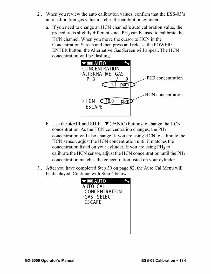
2 . When you review the auto calibration values, confirm that the ESS-03’s auto calibration gas value matches the calibration cylinder.
a. If you need to change an HCN channel’s auto calibration value, the procedure is slightly different since PH3 can be used to calibrate the HCN channel. When you move the cursor to HCN in the Concentration Screen and then press and release the POWER/ENTER button, the Alternative Gas Screen will appear. The HCN concentration will be flashing.
b. Use the ▲AIR and SHIFT ▼ (PANIC) buttons to change the HCN concentration. As the HCN concentration changes, the PH3 concentration will also change. If you are using HCN to calibrate the HCN sensor, adjust the HCN concentration until it matches the concentration listed on your cylinder. If you are using PH3 to calibrate the HCN sensor, adjust the HCN concentration until the PH3 concentration matches the concentration listed on your cylinder.
3 . After you have completed Step 30 on page 82, the Auto Cal Menu will be displayed. Continue with Step 4 below.
AUTO CONCENTRATION ALTERNATIVE GAS PH3 / 9 1.1 ppm
HCN 10.0 ppmESCAPE
HCN concentration
PH3 concentration
AUTO AUTO CAL CONCENTRATION GAS SELECT ESCAPE
GX-6000 Operator’s Manual ESS-03 Calibration • 184
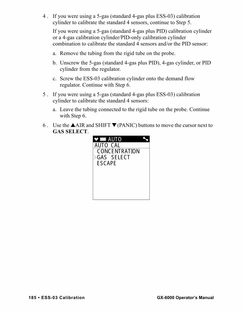
4 . If you were using a 5-gas (standard 4-gas plus ESS-03) calibration cylinder to calibrate the standard 4 sensors, continue to Step 5.If you were using a 5-gas (standard 4-gas plus PID) calibration cylinder or a 4-gas calibration cylinder/PID-only calibration cylinder combination to calibrate the standard 4 sensors and/or the PID sensor:
a. Remove the tubing from the rigid tube on the probe.
b. Unscrew the 5-gas (standard 4-gas plus PID), 4-gas cylinder, or PID cylinder from the regulator.
c. Screw the ESS-03 calibration cylinder onto the demand flow regulator. Continue with Step 6.
5 . If you were using a 5-gas (standard 4-gas plus ESS-03) calibration cylinder to calibrate the standard 4 sensors:
a. Leave the tubing connected to the rigid tube on the probe. Continue with Step 6.
6 . Use the ▲AIR and SHIFT ▼ (PANIC) buttons to move the cursor next to GAS SELECT.
AUTO AUTO CAL CONCENTRATION GAS SELECT ESCAPE
185 • ESS-03 Calibration GX-6000 Operator’s Manual
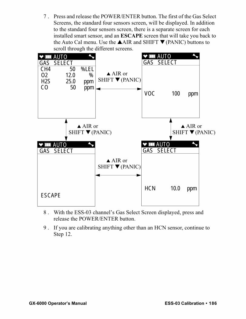
7 . Press and release the POWER/ENTER button. The first of the Gas Select Screens, the standard four sensors screen, will be displayed. In addition to the standard four sensors screen, there is a separate screen for each installed smart sensor, and an ESCAPE screen that will take you back to the Auto Cal menu. Use the ▲AIR and SHIFT ▼ (PANIC) buttons to scroll through the different screens.
8 . With the ESS-03 channel’s Gas Select Screen displayed, press and release the POWER/ENTER button.
9 . If you are calibrating anything other than an HCN sensor, continue to Step 12.
AUTO GAS SELECT CH4 50 %LELO2 12.0 %H2S 25.0 ppmCO 50 ppm
AUTO GAS SELECT
VOC 100 ppm
AUTO GAS SELECT
ESCAPE
▲ AIR orSHIFT ▼ (PANIC)
AUTO
GAS SELECT
HCN 10.0 ppm
▲ AIR orSHIFT ▼ (PANIC)
▲ AIR orSHIFT ▼ (PANIC)
▲ AIR orSHIFT ▼ (PANIC)
GX-6000 Operator’s Manual ESS-03 Calibration • 186
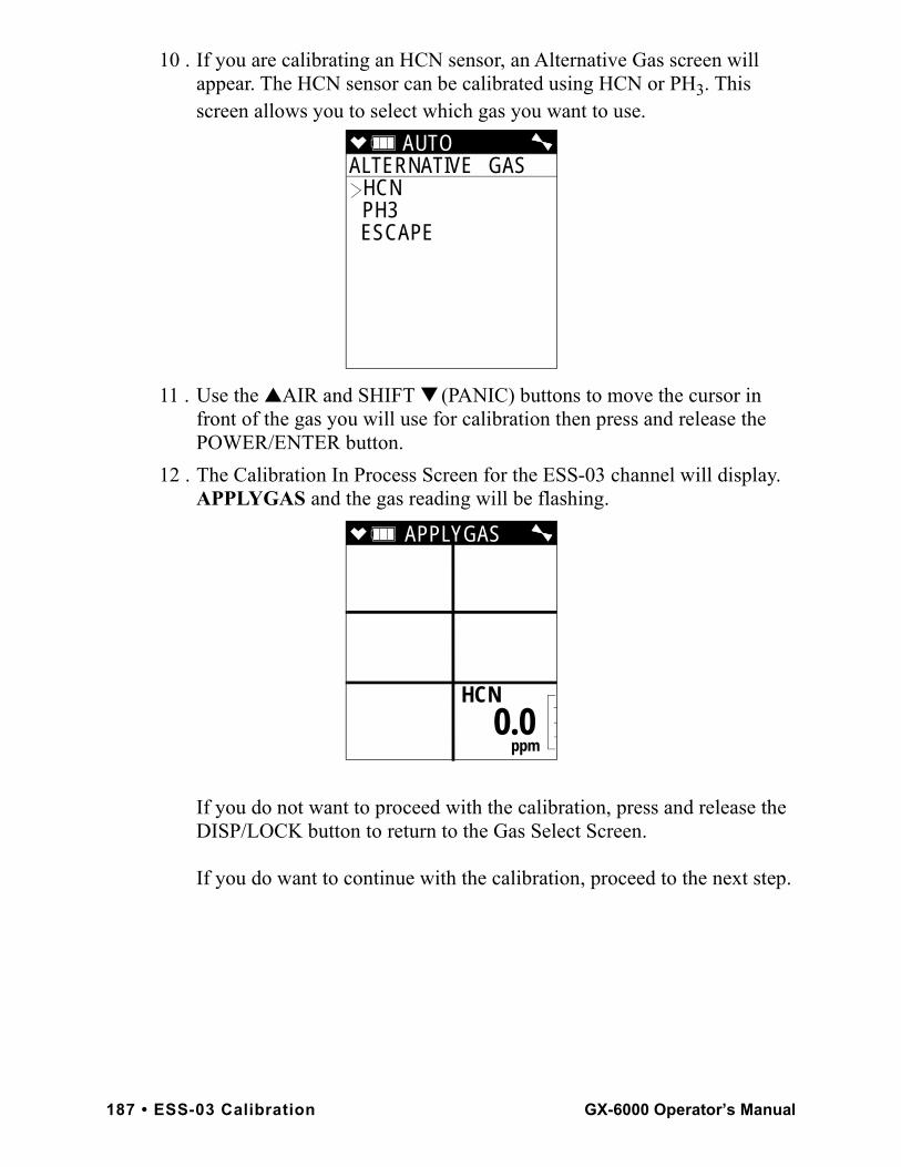
10 . If you are calibrating an HCN sensor, an Alternative Gas screen will appear. The HCN sensor can be calibrated using HCN or PH3. This screen allows you to select which gas you want to use.
11 . Use the ▲AIR and SHIFT ▼ (PANIC) buttons to move the cursor in front of the gas you will use for calibration then press and release the POWER/ENTER button.
12 . The Calibration In Process Screen for the ESS-03 channel will display. APPLYGAS and the gas reading will be flashing.
If you do not want to proceed with the calibration, press and release the DISP/LOCK button to return to the Gas Select Screen.
If you do want to continue with the calibration, proceed to the next step.
AUTO ALTERNATIVE GAS
HCN PH3 ESCAPE
APPLYGAS
HCN
ppm
0.0
187 • ESS-03 Calibration GX-6000 Operator’s Manual
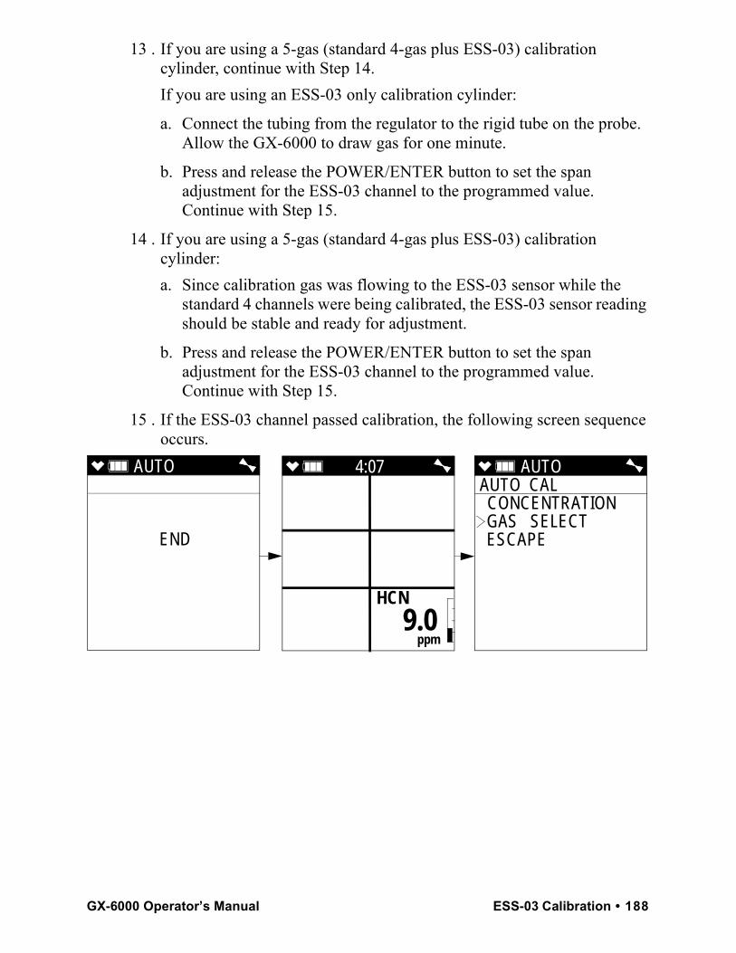
13 . If you are using a 5-gas (standard 4-gas plus ESS-03) calibration cylinder, continue with Step 14.If you are using an ESS-03 only calibration cylinder:
a. Connect the tubing from the regulator to the rigid tube on the probe. Allow the GX-6000 to draw gas for one minute.
b. Press and release the POWER/ENTER button to set the span adjustment for the ESS-03 channel to the programmed value. Continue with Step 15.
14 . If you are using a 5-gas (standard 4-gas plus ESS-03) calibration cylinder:
a. Since calibration gas was flowing to the ESS-03 sensor while the standard 4 channels were being calibrated, the ESS-03 sensor reading should be stable and ready for adjustment.
b. Press and release the POWER/ENTER button to set the span adjustment for the ESS-03 channel to the programmed value. Continue with Step 15.
15 . If the ESS-03 channel passed calibration, the following screen sequence occurs.
AUTO
END
AUTO AUTO CAL CONCENTRATION GAS SELECT ESCAPE
4:07
HCN
ppm
9.0
GX-6000 Operator’s Manual ESS-03 Calibration • 188
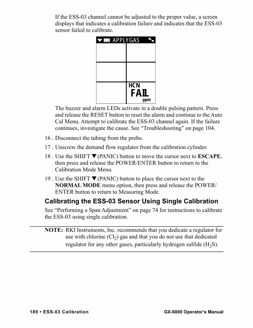
If the ESS-03 channel cannot be adjusted to the proper value, a screen displays that indicates a calibration failure and indicates that the ESS-03 sensor failed to calibrate.
The buzzer and alarm LEDs activate in a double pulsing pattern. Press and release the RESET button to reset the alarm and continue to the Auto Cal Menu. Attempt to calibrate the ESS-03 channel again. If the failure continues, investigate the cause. See “Troubleshooting” on page 104.
16 . Disconnect the tubing from the probe.17 . Unscrew the demand flow regulator from the calibration cylinder.18 . Use the SHIFT ▼ (PANIC) button to move the cursor next to ESCAPE,
then press and release the POWER/ENTER button to return to the Calibration Mode Menu.
19 . Use the SHIFT ▼ (PANIC) button to place the cursor next to the NORMAL MODE menu option, then press and release the POWER/ENTER button to return to Measuring Mode.
Calibrating the ESS-03 Sensor Using Single CalibrationSee “Performing a Span Adjustment” on page 74 for instructions to calibrate the ESS-03 using single calibration.
NOTE: RKI Instruments, Inc. recommends that you dedicate a regulator for use with chlorine (Cl2) gas and that you do not use that dedicated regulator for any other gases, particularly hydrogen sulfide (H2S).
APPLYGAS
HCN
ppm
FAIL
189 • ESS-03 Calibration GX-6000 Operator’s Manual
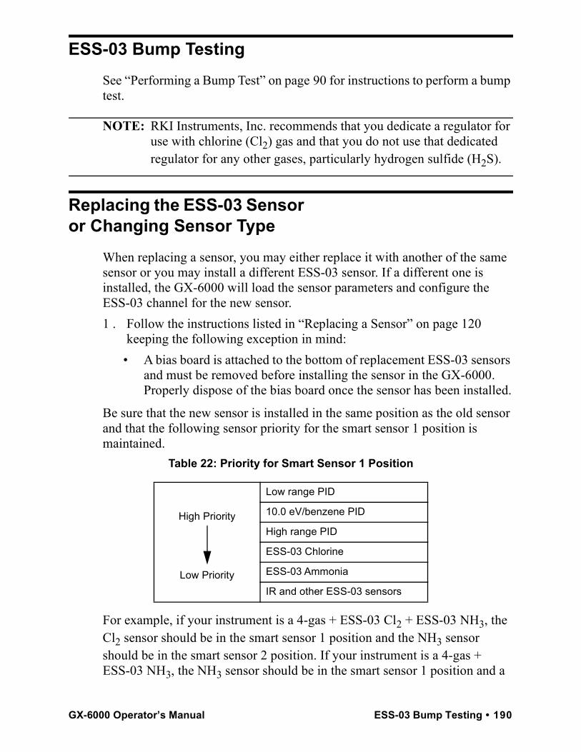
ESS-03 Bump TestingSee “Performing a Bump Test” on page 90 for instructions to perform a bump test.
NOTE: RKI Instruments, Inc. recommends that you dedicate a regulator for use with chlorine (Cl2) gas and that you do not use that dedicated regulator for any other gases, particularly hydrogen sulfide (H2S).
Replacing the ESS-03 Sensor or Changing Sensor Type
When replacing a sensor, you may either replace it with another of the same sensor or you may install a different ESS-03 sensor. If a different one is installed, the GX-6000 will load the sensor parameters and configure the ESS-03 channel for the new sensor.1 . Follow the instructions listed in “Replacing a Sensor” on page 120
keeping the following exception in mind:• A bias board is attached to the bottom of replacement ESS-03 sensors
and must be removed before installing the sensor in the GX-6000. Properly dispose of the bias board once the sensor has been installed.
Be sure that the new sensor is installed in the same position as the old sensor and that the following sensor priority for the smart sensor 1 position is maintained.
Table 22: Priority for Smart Sensor 1 Position
For example, if your instrument is a 4-gas + ESS-03 Cl2 + ESS-03 NH3, the Cl2 sensor should be in the smart sensor 1 position and the NH3 sensor should be in the smart sensor 2 position. If your instrument is a 4-gas + ESS-03 NH3, the NH3 sensor should be in the smart sensor 1 position and a
High Priority
Low Priority
Low range PID
10.0 eV/benzene PID
High range PID
ESS-03 Chlorine
ESS-03 Ammonia
IR and other ESS-03 sensors
GX-6000 Operator’s Manual ESS-03 Bump Testing • 190
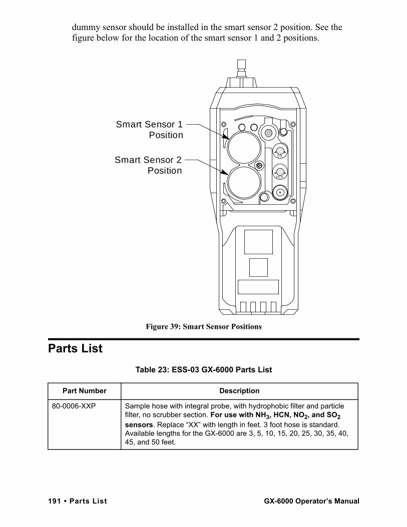
dummy sensor should be installed in the smart sensor 2 position. See the figure below for the location of the smart sensor 1 and 2 positions.
Figure 39: Smart Sensor Positions
Parts ListTable 23: ESS-03 GX-6000 Parts List
Part Number Description
80-0006-XXP Sample hose with integral probe, with hydrophobic filter and particle filter, no scrubber section. For use with NH3, HCN, NO2, and SO2 sensors. Replace “XX” with length in feet. 3 foot hose is standard. Available lengths for the GX-6000 are 3, 5, 10, 15, 20, 25, 30, 35, 40, 45, and 50 feet.
H2S
CO
Smart Sensor 1 Position
Smart Sensor 2 Position
191 • Parts List GX-6000 Operator’s Manual
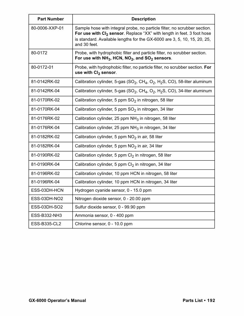
80-0006-XXP-01 Sample hose with integral probe, no particle filter, no scrubber section. For use with Cl2 sensor. Replace “XX” with length in feet. 3 foot hose is standard. Available lengths for the GX-6000 are 3, 5, 10, 15, 20, 25, and 30 feet.
80-0172 Probe, with hydrophobic filter and particle filter, no scrubber section. For use with NH3, HCN, NO2, and SO2 sensors.
80-0172-01 Probe, with hydrophobic filter, no particle filter, no scrubber section. For use with Cl2 sensor.
81-0142RK-02 Calibration cylinder, 5-gas (SO2, CH4, O2, H2S, CO), 58-liter aluminum
81-0142RK-04 Calibration cylinder, 5-gas (SO2, CH4, O2, H2S, CO), 34-liter aluminum
81-0170RK-02 Calibration cylinder, 5 ppm SO2 in nitrogen, 58 liter
81-0170RK-04 Calibration cylinder, 5 ppm SO2 in nitrogen, 34 liter
81-0176RK-02 Calibration cylinder, 25 ppm NH3 in nitrogen, 58 liter
81-0176RK-04 Calibration cylinder, 25 ppm NH3 in nitrogen, 34 liter
81-0182RK-02 Calibration cylinder, 5 ppm NO2 in air, 58 liter
81-0182RK-04 Calibration cylinder, 5 ppm NO2 in air, 34 liter
81-0190RK-02 Calibration cylinder, 5 ppm Cl2 in nitrogen, 58 liter
81-0190RK-04 Calibration cylinder, 5 ppm Cl2 in nitrogen, 34 liter
81-0196RK-02 Calibration cylinder, 10 ppm HCN in nitrogen, 58 liter
81-0196RK-04 Calibration cylinder, 10 ppm HCN in nitrogen, 34 liter
ESS-03DH-HCN Hydrogen cyanide sensor, 0 - 15.0 ppm
ESS-03DH-NO2 Nitrogen dioxide sensor, 0 - 20.00 ppm
ESS-03DH-SO2 Sulfur dioxide sensor, 0 - 99.90 ppm
ESS-B332-NH3 Ammonia sensor, 0 - 400 ppm
ESS-B335-CL2 Chlorine sensor, 0 - 10.0 ppm
Part Number Description
GX-6000 Operator’s Manual Parts List • 192
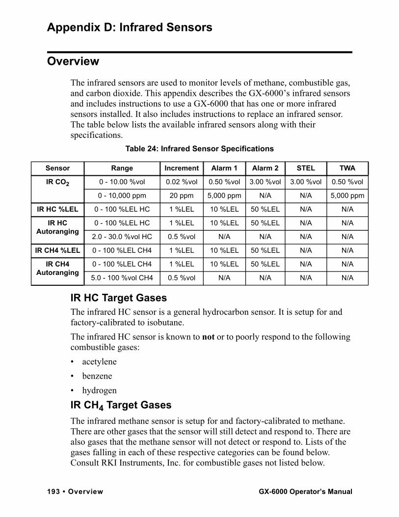
l
m
IR
A
IR
A
Appendix D: Infrared Sensors
OverviewThe infrared sensors are used to monitor levels of methane, combustible gas, and carbon dioxide. This appendix describes the GX-6000’s infrared sensors and includes instructions to use a GX-6000 that has one or more infrared sensors installed. It also includes instructions to replace an infrared sensor. The table below lists the available infrared sensors along with their specifications.
Table 24: Infrared Sensor Specifications
IR HC Target GasesThe infrared HC sensor is a general hydrocarbon sensor. It is setup for and factory-calibrated to isobutane. The infrared HC sensor is known to not or to poorly respond to the following combustible gases:• acetylene• benzene• hydrogenIR CH4 Target GasesThe infrared methane sensor is setup for and factory-calibrated to methane. There are other gases that the sensor will still detect and respond to. There are also gases that the methane sensor will not detect or respond to. Lists of the gases falling in each of these respective categories can be found below. Consult RKI Instruments, Inc. for combustible gases not listed below.
Sensor Range Increment Alarm 1 Alarm 2 STEL TWA
IR CO2 0 - 10.00 %vol 0.02 %vol 0.50 %vol 3.00 %vol 3.00 %vol 0.50 %vo
0 - 10,000 ppm 20 ppm 5,000 ppm N/A N/A 5,000 pp
HC %LEL 0 - 100 %LEL HC 1 %LEL 10 %LEL 50 %LEL N/A N/A
IR HC utoranging
0 - 100 %LEL HC 1 %LEL 10 %LEL 50 %LEL N/A N/A
2.0 - 30.0 %vol HC 0.5 %vol N/A N/A N/A N/A
CH4 %LEL 0 - 100 %LEL CH4 1 %LEL 10 %LEL 50 %LEL N/A N/A
IR CH4 utoranging
0 - 100 %LEL CH4 1 %LEL 10 %LEL 50 %LEL N/A N/A
5.0 - 100 %vol CH4 0.5 %vol N/A N/A N/A N/A
193 • Overview GX-6000 Operator’s Manual
The infrared methane sensor is known to respond to the following combustible gases:• acetone• ethane• ethanol• hexane• IPA• isobutane• MEK• methanol• propane• styrene• tolueneThe infrared methane sensor is known to not or to poorly respond to the following combustible gases:• acetylene• benzene• hydrogen
Description
IR SensorThe IR sensor is a smart sensor that stores sensor parameters including the target gas, detection range, alarm points, and calibration settings in its memory. So a sensor can be calibrated at the factory and shipped as a replacement sensor without the need to calibrate the sensor when it is installed as long as it is installed during the sensor’s valid calibration period which is typically 6 months. In addition, you can change an existing IR channel from one type of IR sensor to another and the GX-6000 will automatically load all the sensor parameters and configure the IR channel for the new sensor. See “Replacing an IR Sensor” on page 200 for instructions to replace or change an IR sensor. The IR sensor is a cylindrical sensor with a diffusion opening on the front and a connector on the back. The IR sensor is installed in one of the two smart sensor sockets and is held in place by the sensor gasket and the flow chamber.
GX-6000 Operator’s Manual Description • 194
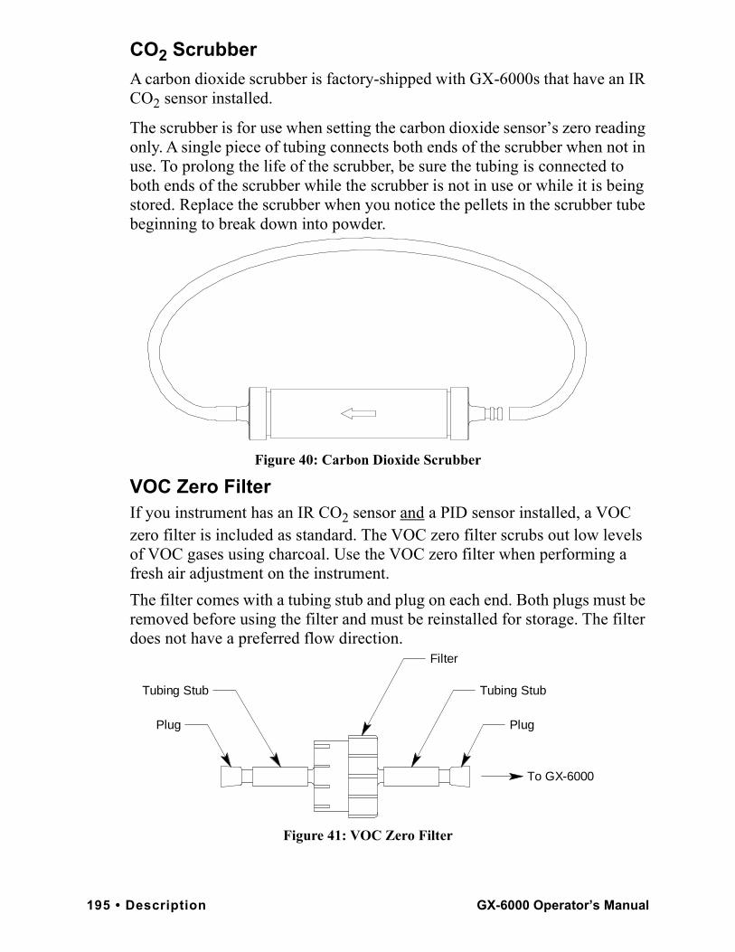
CO2 ScrubberA carbon dioxide scrubber is factory-shipped with GX-6000s that have an IR CO2 sensor installed.
The scrubber is for use when setting the carbon dioxide sensor’s zero reading only. A single piece of tubing connects both ends of the scrubber when not in use. To prolong the life of the scrubber, be sure the tubing is connected to both ends of the scrubber while the scrubber is not in use or while it is being stored. Replace the scrubber when you notice the pellets in the scrubber tube beginning to break down into powder.
Figure 40: Carbon Dioxide Scrubber
VOC Zero FilterIf you instrument has an IR CO2 sensor and a PID sensor installed, a VOC zero filter is included as standard. The VOC zero filter scrubs out low levels of VOC gases using charcoal. Use the VOC zero filter when performing a fresh air adjustment on the instrument.The filter comes with a tubing stub and plug on each end. Both plugs must be removed before using the filter and must be reinstalled for storage. The filter does not have a preferred flow direction.
Figure 41: VOC Zero Filter
Filter
Plug
Tubing StubTubing Stub
Plug
To GX-6000
195 • Description GX-6000 Operator’s Manual
IR HC Start Up and Normal OperationFor instructions to startup and use a GX-6000 that includes an infrared hydrocarbon sensor, reference “Start Up” on page 19, “Measuring Mode, Normal Operation” on page 29, and “Measuring Mode, Alarms” on page 36.0-100 %LEL/2.0-30.0 %vol AutorangingThe infrared hydrocarbon sensor can be factory set to detect gas in a 0-100 %LEL configuration or an autoranging configuration. The autoranging configuration detects gas on a 0-100 %LEL and a 2.0-30.0 %vol scale. The gas reading will be displayed in %LEL until the gas level reaches 100 %LEL, or 2.0 %vol for isobutane. Once the gas reading is above 100 %LEL, it is displayed in %vol. Alarm points exist for the %LEL range but do not exist for the %vol range. If %LEL range alarms are not silenced (see pg.159 for a description of the alarm silence feature) and the gas level increases to %vol levels, the alarms will continue to sound but no new alarms will occur.• If a CO sensor is installed and its charcoal filter becomes saturated, the
presence of hydrocarbons may produce a reading on the CO channel.• If a PID sensor is installed in your instrument, the presence of
hydrocarbons that the IR HC sensor is intended to detect may produce upscale readings on the PID channel.
IR CH4 Start Up and Normal Operation
For instructions to startup and use a GX-6000 that includes an infrared methane sensor, reference “Start Up” on page 19, “Measuring Mode, Normal Operation” on page 29, and “Measuring Mode, Alarms” on page 36.0 - 100 %LEL/5.0 - 100.0 %vol AutorangingThe infrared methane sensor can be factory set to detect gas in a 0-100 %LEL configuration or an autoranging configuration. The autoranging configuration detects gas on a 0-100 %LEL and a 5.0-100.0 %vol scale. The gas reading will be displayed in %LEL until the gas level reaches 100 %LEL, or 5.0 %vol for methane. Once the gas reading is above 100 %LEL, it is displayed in %vol. Alarm points exist for the %LEL range but do not exist for the %vol range. If %LEL range alarms are not silenced (see pg.159 for a description of the alarm silence feature) and the gas level increases to %vol levels, the alarms will continue to sound but no new alarms will occur.• If a PID sensor is installed in your instrument and concentrations of
methane greater than 100 %LEL are present in the monitoring environment, the PID channel’s reading will be suppressed.
GX-6000 Operator’s Manual IR HC Start Up and Normal Operation • 196

IR CO2 Start Up and Normal Operation
For instructions to startup and use a GX-6000 that includes an infrared CO2 sensor, reference “Start Up” on page 19, “Measuring Mode, Normal Operation” on page 29, and “Measuring Mode, Alarms” on page 36. Follow these instructions keeping the following special considerations in mind:• A background level of CO2 exists in fresh air. Table 25 below indicates a
typical gas reading in fresh air.
• When you perform a demand zero during start up, operation, or calibration, you must use the CO2 scrubber provided with the instrument to remove background CO2 from the air being sampled. See “Performing a Demand Zero for Carbon Dioxide Sensors” below. If you have a PID sensor in your instrument, see “Performing a Demand Zero for Instruments with a Carbon Dioxide Sensor and a PID Sensor” on page 198.
• Since there is a background of CO2 in air, do not use the AUTO ZERO feature that can be turned on and off in Maintenance Mode. The factory setting for the feature is OFF.
Performing a Demand Zero for Carbon Dioxide SensorsWhen setting the zero reading, the carbon dioxide scrubber shipped with the GX-6000 allows you to eliminate carbon dioxide normally found in fresh air. To perform a demand zero, do the following:1 . Remove the tubing from the side of the scrubber that does not have an
arrow pointing to it.
Table 25: Carbon Dioxide Fresh Air Readings
Sensor Range Approximate Fresh Air Reading
0 - 10 %vol 0.04 %vol
0 - 10,000 ppm 400 ppm
197 • IR CO2 Start Up and Normal Operation GX-6000 Operator’s Manual
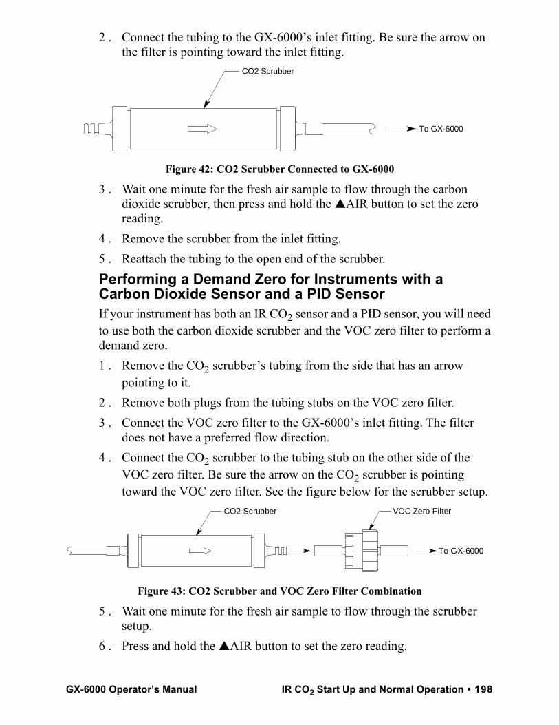
2 . Connect the tubing to the GX-6000’s inlet fitting. Be sure the arrow on the filter is pointing toward the inlet fitting.
Figure 42: CO2 Scrubber Connected to GX-6000
3 . Wait one minute for the fresh air sample to flow through the carbon dioxide scrubber, then press and hold the ▲AIR button to set the zero reading.
4 . Remove the scrubber from the inlet fitting.5 . Reattach the tubing to the open end of the scrubber.Performing a Demand Zero for Instruments with a Carbon Dioxide Sensor and a PID SensorIf your instrument has both an IR CO2 sensor and a PID sensor, you will need to use both the carbon dioxide scrubber and the VOC zero filter to perform a demand zero.1 . Remove the CO2 scrubber’s tubing from the side that has an arrow
pointing to it.2 . Remove both plugs from the tubing stubs on the VOC zero filter.3 . Connect the VOC zero filter to the GX-6000’s inlet fitting. The filter
does not have a preferred flow direction.4 . Connect the CO2 scrubber to the tubing stub on the other side of the
VOC zero filter. Be sure the arrow on the CO2 scrubber is pointing toward the VOC zero filter. See the figure below for the scrubber setup.
Figure 43: CO2 Scrubber and VOC Zero Filter Combination
5 . Wait one minute for the fresh air sample to flow through the scrubber setup.
6 . Press and hold the ▲AIR button to set the zero reading.
To GX-6000
CO2 Scrubber
VOC Zero FilterCO2 Scrubber
To GX-6000
GX-6000 Operator’s Manual IR CO2 Start Up and Normal Operation • 198
7 . Remove the CO2 scrubber from the VOC zero filter. Be sure the VOC zero filter’s tubing stays on the VOC zero filter.
8 . Reattach the CO2 scrubber’s tubing to the open end of the scrubber.
9 . Remove the VOC zero filter from the GX-6000’s inlet fitting.10 . Reinstall the plugs on each end of the VOC zero filter.
NOTE: Do not store the CO2 scrubber and VOC zero filter connected together. They must be separated and appropriately plugged for storage.
IR Calibration1 . See “Calibrating Using the Auto Calibration Method” on page 71 or
“Calibrating Using the Single Calibration Method” on page 84 for instructions to perform a calibration.
NOTE: If you are using the IR HC or IR CH4 sensors in their autoranging configuration, be sure to calibrate the range you’d like the most accuracy in (either %LEL or %vol).
NOTE: If there is a PID sensor installed in your instrument and you are calibrating an IR CH4 sensor with %vol concentrations, either calibrate the PID sensor first or allow enough time for the %vol CH4 gas to flush out before calibrating the PID sensor.
IR Bump Testing1 . See “Performing a Bump Test” on page 90 for instructions to perform a
bump test.
199 • IR Calibration GX-6000 Operator’s Manual
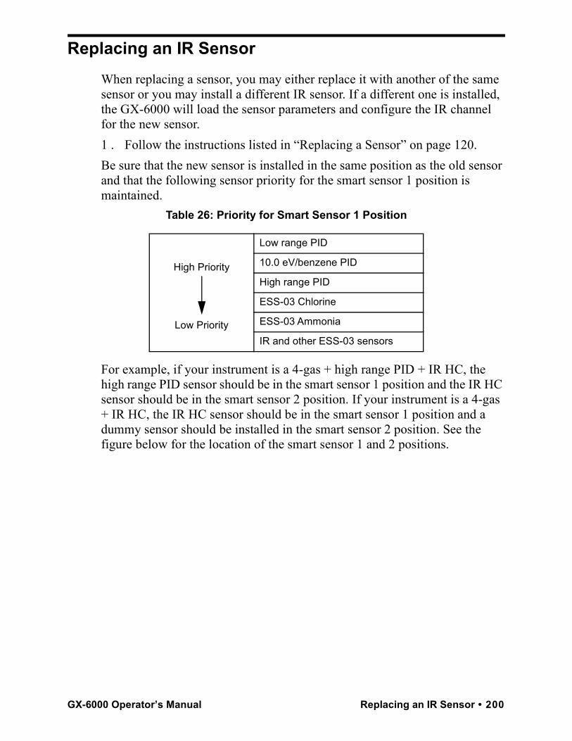
Replacing an IR SensorWhen replacing a sensor, you may either replace it with another of the same sensor or you may install a different IR sensor. If a different one is installed, the GX-6000 will load the sensor parameters and configure the IR channel for the new sensor.1 . Follow the instructions listed in “Replacing a Sensor” on page 120.Be sure that the new sensor is installed in the same position as the old sensor and that the following sensor priority for the smart sensor 1 position is maintained.
Table 26: Priority for Smart Sensor 1 Position
For example, if your instrument is a 4-gas + high range PID + IR HC, the high range PID sensor should be in the smart sensor 1 position and the IR HC sensor should be in the smart sensor 2 position. If your instrument is a 4-gas + IR HC, the IR HC sensor should be in the smart sensor 1 position and a dummy sensor should be installed in the smart sensor 2 position. See the figure below for the location of the smart sensor 1 and 2 positions.
High Priority
Low Priority
Low range PID
10.0 eV/benzene PID
High range PID
ESS-03 Chlorine
ESS-03 Ammonia
IR and other ESS-03 sensors
GX-6000 Operator’s Manual Replacing an IR Sensor • 200
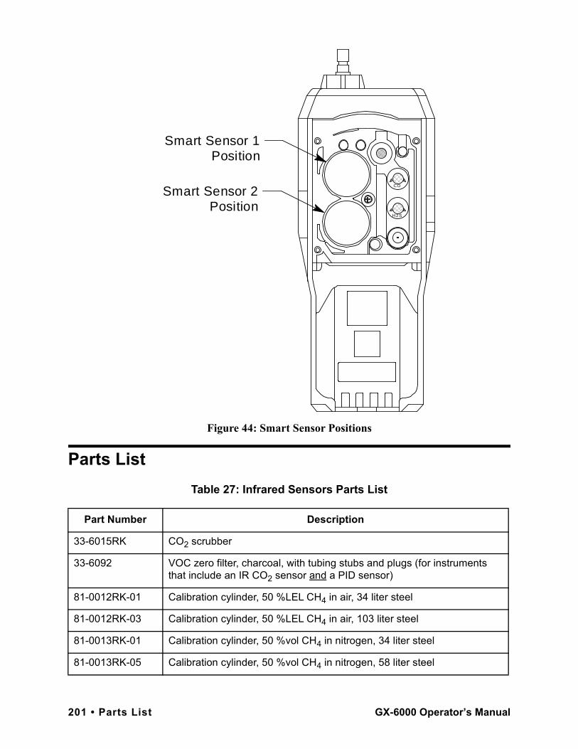
Figure 44: Smart Sensor Positions
Parts ListTable 27: Infrared Sensors Parts List
Part Number Description
33-6015RK CO2 scrubber
33-6092 VOC zero filter, charcoal, with tubing stubs and plugs (for instruments that include an IR CO2 sensor and a PID sensor)
81-0012RK-01 Calibration cylinder, 50 %LEL CH4 in air, 34 liter steel
81-0012RK-03 Calibration cylinder, 50 %LEL CH4 in air, 103 liter steel
81-0013RK-01 Calibration cylinder, 50 %vol CH4 in nitrogen, 34 liter steel
81-0013RK-05 Calibration cylinder, 50 %vol CH4 in nitrogen, 58 liter steel
H2S
CO
Smart Sensor 1 Position
Smart Sensor 2 Position
201 • Parts List GX-6000 Operator’s Manual
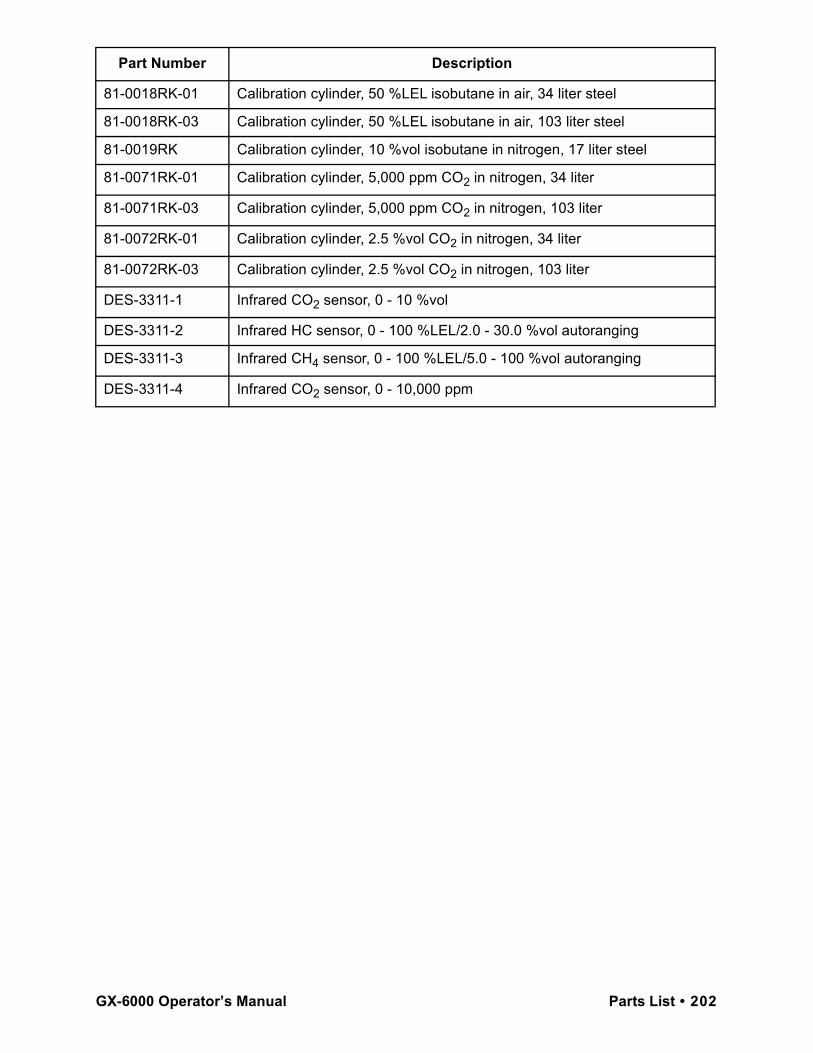
81-0018RK-01 Calibration cylinder, 50 %LEL isobutane in air, 34 liter steel
81-0018RK-03 Calibration cylinder, 50 %LEL isobutane in air, 103 liter steel
81-0019RK Calibration cylinder, 10 %vol isobutane in nitrogen, 17 liter steel
81-0071RK-01 Calibration cylinder, 5,000 ppm CO2 in nitrogen, 34 liter
81-0071RK-03 Calibration cylinder, 5,000 ppm CO2 in nitrogen, 103 liter
81-0072RK-01 Calibration cylinder, 2.5 %vol CO2 in nitrogen, 34 liter
81-0072RK-03 Calibration cylinder, 2.5 %vol CO2 in nitrogen, 103 liter
DES-3311-1 Infrared CO2 sensor, 0 - 10 %vol
DES-3311-2 Infrared HC sensor, 0 - 100 %LEL/2.0 - 30.0 %vol autoranging
DES-3311-3 Infrared CH4 sensor, 0 - 100 %LEL/5.0 - 100 %vol autoranging
DES-3311-4 Infrared CO2 sensor, 0 - 10,000 ppm
Part Number Description
GX-6000 Operator’s Manual Parts List • 202
Appendix E: Using the GX-6000 in Leak Check Mode
OverviewThis chapter explains how to operate the GX-6000 in Leak Check Mode. Leak Check Mode is used to pinpoint small leaks of combustible gas from valves, flanges, connections, and other potential leak points. When the GX-6000 is in Leak Check Mode, only the catalytic combustible sensor and potentially the CO sensor, depending on the setting of the CO DISPLAY parameter in Maintenance Mode, will be active.
NOTE: If the CO DISPLAY parameter in Maintenance Mode is set to ON, the CO channel will appear in Leak Check Mode. If the CO DISPLAY parameter is set to OFF (factory setting), the CO channel will not appear in Leak Check Mode. All screens in this section do not show the CO channel. If your instrument’s CO DISPLAY is set to ON, your screens may appear different.
If a GX-6000 is intended for tracking down leaks, it is shipped with Leak Check Mode or both Leak Check Mode and Bar Hole Mode enabled so that the operator must choose which operational mode to use when the unit is turned on (see “Updating the Leak Check/Bar Hole Mode Setting” on page 164).
Start Up, Leak Check ModeThis section explains how to start up the GX-6000 in Leak Check Mode and get it ready for operation.Turning On the GX-6000, Leak Check ModeCAUTION: If one or more sensors other than a catalytic combustible sensor
is installed, these sensors will not be active while the GX-6000 is in Leak Check Mode.
NOTE: In order for LEAK CHECK MODE to appear as a selection in the Mode Select Screen, the L./B. MODE item in Maintenance Mode must be set to LEAK CHECK MODE or LEAK CHECK MODE BAR HOLE MODE. The factory setting is OFF.
1 . Connect the tapered rubber nozzle or the sample hose and probe to the
203 • Overview GX-6000 Operator’s Manual
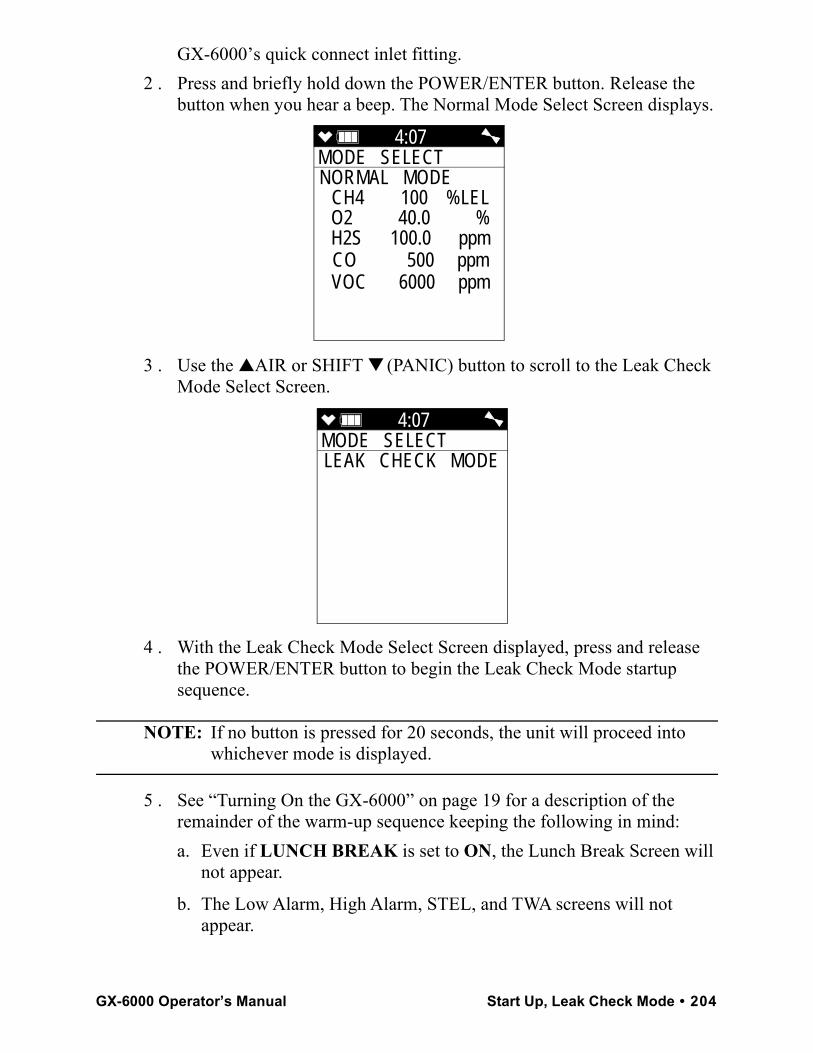
GX-6000’s quick connect inlet fitting.2 . Press and briefly hold down the POWER/ENTER button. Release the
button when you hear a beep. The Normal Mode Select Screen displays.
3 . Use the ▲AIR or SHIFT ▼ (PANIC) button to scroll to the Leak Check Mode Select Screen.
4 . With the Leak Check Mode Select Screen displayed, press and release the POWER/ENTER button to begin the Leak Check Mode startup sequence.
NOTE: If no button is pressed for 20 seconds, the unit will proceed into whichever mode is displayed.
5 . See “Turning On the GX-6000” on page 19 for a description of the remainder of the warm-up sequence keeping the following in mind:
a. Even if LUNCH BREAK is set to ON, the Lunch Break Screen will not appear.
b. The Low Alarm, High Alarm, STEL, and TWA screens will not appear.
4:07MODE SELECT NORMAL MODE
CH4 100 %LELO2 40.0 %H2S 100.0 ppmCO 500 ppmVOC 6000 ppm
4:07MODE SELECT LEAK CHECK MODE
GX-6000 Operator’s Manual Start Up, Leak Check Mode • 204
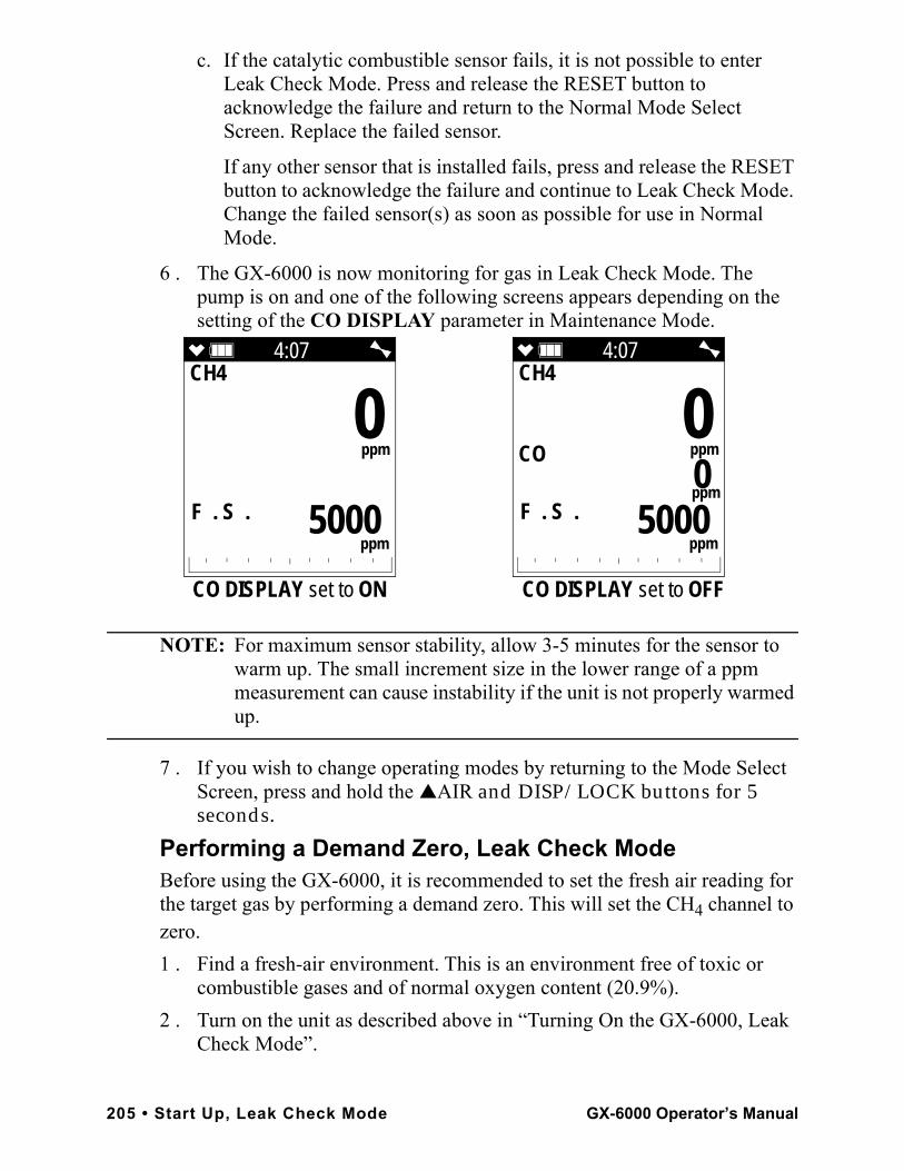
c. If the catalytic combustible sensor fails, it is not possible to enter Leak Check Mode. Press and release the RESET button to acknowledge the failure and return to the Normal Mode Select Screen. Replace the failed sensor.
If any other sensor that is installed fails, press and release the RESET button to acknowledge the failure and continue to Leak Check Mode. Change the failed sensor(s) as soon as possible for use in Normal Mode.
6 . The GX-6000 is now monitoring for gas in Leak Check Mode. The pump is on and one of the following screens appears depending on the setting of the CO DISPLAY parameter in Maintenance Mode.
NOTE: For maximum sensor stability, allow 3-5 minutes for the sensor to warm up. The small increment size in the lower range of a ppm measurement can cause instability if the unit is not properly warmed up.
7 . If you wish to change operating modes by returning to the Mode Select Screen, press and hold the ▲AIR and DISP/LOCK buttons for 5 seconds.
Performing a Demand Zero, Leak Check ModeBefore using the GX-6000, it is recommended to set the fresh air reading for the target gas by performing a demand zero. This will set the CH4 channel to zero.1 . Find a fresh-air environment. This is an environment free of toxic or
combustible gases and of normal oxygen content (20.9%).2 . Turn on the unit as described above in “Turning On the GX-6000, Leak
Check Mode”.
4:07CH4
F . S .
0
ppm
5000 ppm
4:07CH4
F . S .
0
ppm
5000 ppm
CO
ppm 0
CO DISPLAY set to ON CO DISPLAY set to OFF
205 • Start Up, Leak Check Mode GX-6000 Operator’s Manual
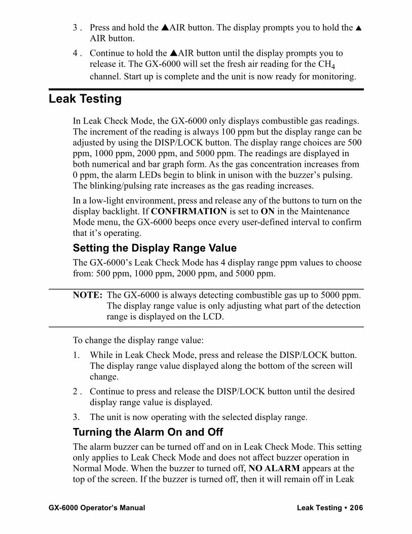
3 . Press and hold the ▲AIR button. The display prompts you to hold the ▲ AIR button.
4 . Continue to hold the ▲AIR button until the display prompts you to release it. The GX-6000 will set the fresh air reading for the CH4 channel. Start up is complete and the unit is now ready for monitoring.
Leak TestingIn Leak Check Mode, the GX-6000 only displays combustible gas readings. The increment of the reading is always 100 ppm but the display range can be adjusted by using the DISP/LOCK button. The display range choices are 500 ppm, 1000 ppm, 2000 ppm, and 5000 ppm. The readings are displayed in both numerical and bar graph form. As the gas concentration increases from 0 ppm, the alarm LEDs begin to blink in unison with the buzzer’s pulsing. The blinking/pulsing rate increases as the gas reading increases. In a low-light environment, press and release any of the buttons to turn on the display backlight. If CONFIRMATION is set to ON in the Maintenance Mode menu, the GX-6000 beeps once every user-defined interval to confirm that it’s operating.Setting the Display Range ValueThe GX-6000’s Leak Check Mode has 4 display range ppm values to choose from: 500 ppm, 1000 ppm, 2000 ppm, and 5000 ppm.
NOTE: The GX-6000 is always detecting combustible gas up to 5000 ppm. The display range value is only adjusting what part of the detection range is displayed on the LCD.
To change the display range value:1. While in Leak Check Mode, press and release the DISP/LOCK button.
The display range value displayed along the bottom of the screen will change.
2 . Continue to press and release the DISP/LOCK button until the desired display range value is displayed.
3. The unit is now operating with the selected display range.Turning the Alarm On and OffThe alarm buzzer can be turned off and on in Leak Check Mode. This setting only applies to Leak Check Mode and does not affect buzzer operation in Normal Mode. When the buzzer to turned off, NO ALARM appears at the top of the screen. If the buzzer is turned off, then it will remain off in Leak
GX-6000 Operator’s Manual Leak Testing • 206
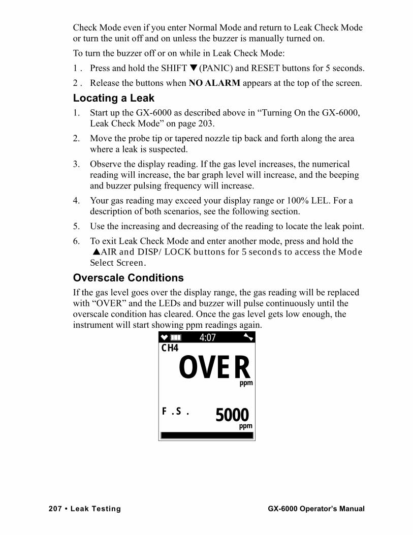
Check Mode even if you enter Normal Mode and return to Leak Check Mode or turn the unit off and on unless the buzzer is manually turned on.To turn the buzzer off or on while in Leak Check Mode:1 . Press and hold the SHIFT ▼ (PANIC) and RESET buttons for 5 seconds.2 . Release the buttons when NO ALARM appears at the top of the screen.Locating a Leak1. Start up the GX-6000 as described above in “Turning On the GX-6000,
Leak Check Mode” on page 203.2. Move the probe tip or tapered nozzle tip back and forth along the area
where a leak is suspected. 3. Observe the display reading. If the gas level increases, the numerical
reading will increase, the bar graph level will increase, and the beeping and buzzer pulsing frequency will increase.
4. Your gas reading may exceed your display range or 100% LEL. For a description of both scenarios, see the following section.
5. Use the increasing and decreasing of the reading to locate the leak point.6. To exit Leak Check Mode and enter another mode, press and hold the
▲AIR and DISP/LOCK buttons for 5 seconds to access the Mode Select Screen.
Overscale ConditionsIf the gas level goes over the display range, the gas reading will be replaced with “OVER” and the LEDs and buzzer will pulse continuously until the overscale condition has cleared. Once the gas level gets low enough, the instrument will start showing ppm readings again.
4:07CH4
F . S .
ppm
5000 ppm
OVER
207 • Leak Testing GX-6000 Operator’s Manual
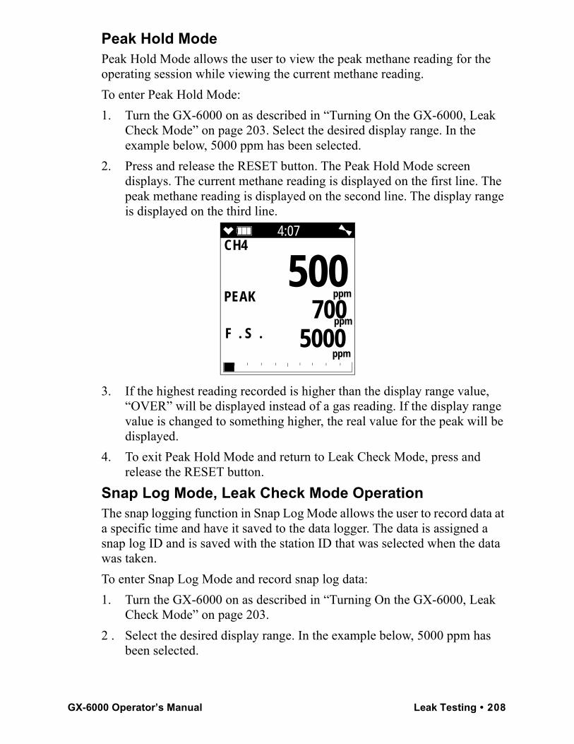
Peak Hold ModePeak Hold Mode allows the user to view the peak methane reading for the operating session while viewing the current methane reading.To enter Peak Hold Mode:1. Turn the GX-6000 on as described in “Turning On the GX-6000, Leak
Check Mode” on page 203. Select the desired display range. In the example below, 5000 ppm has been selected.
2. Press and release the RESET button. The Peak Hold Mode screen displays. The current methane reading is displayed on the first line. The peak methane reading is displayed on the second line. The display range is displayed on the third line.
3. If the highest reading recorded is higher than the display range value, “OVER” will be displayed instead of a gas reading. If the display range value is changed to something higher, the real value for the peak will be displayed.
4. To exit Peak Hold Mode and return to Leak Check Mode, press and release the RESET button.
Snap Log Mode, Leak Check Mode OperationThe snap logging function in Snap Log Mode allows the user to record data at a specific time and have it saved to the data logger. The data is assigned a snap log ID and is saved with the station ID that was selected when the data was taken.To enter Snap Log Mode and record snap log data:1. Turn the GX-6000 on as described in “Turning On the GX-6000, Leak
Check Mode” on page 203. 2 . Select the desired display range. In the example below, 5000 ppm has
been selected.
4:07CH4
F . S .
500
ppm
5000 ppm
PEAK
ppm 700
GX-6000 Operator’s Manual Leak Testing • 208
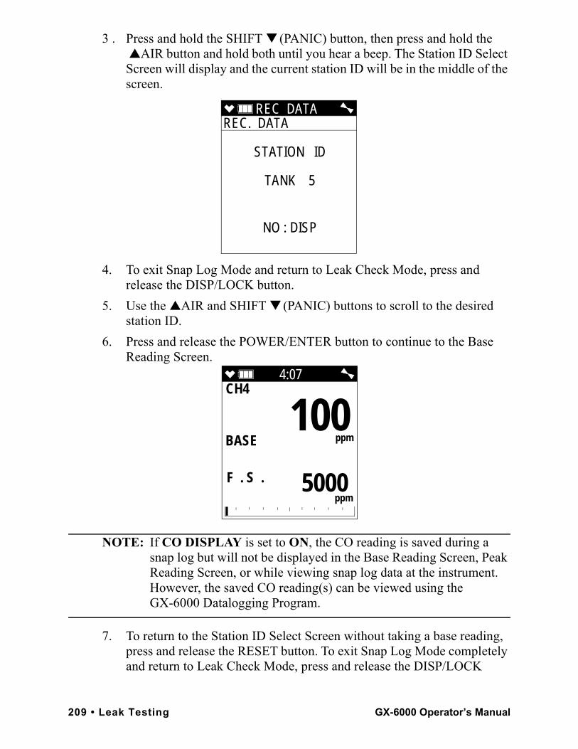
3 . Press and hold the SHIFT ▼ (PANIC) button, then press and hold the ▲AIR button and hold both until you hear a beep. The Station ID Select Screen will display and the current station ID will be in the middle of the screen.
4. To exit Snap Log Mode and return to Leak Check Mode, press and release the DISP/LOCK button.
5. Use the ▲AIR and SHIFT ▼ (PANIC) buttons to scroll to the desired station ID.
6. Press and release the POWER/ENTER button to continue to the Base Reading Screen.
NOTE: If CO DISPLAY is set to ON, the CO reading is saved during a snap log but will not be displayed in the Base Reading Screen, Peak Reading Screen, or while viewing snap log data at the instrument. However, the saved CO reading(s) can be viewed using the GX-6000 Datalogging Program.
7. To return to the Station ID Select Screen without taking a base reading, press and release the RESET button. To exit Snap Log Mode completely and return to Leak Check Mode, press and release the DISP/LOCK
REC DATA REC. DATA
STATION ID
TANK 5
NO : DISP
4:07CH4
F . S .
100
ppm
5000 ppm
BASE
209 • Leak Testing GX-6000 Operator’s Manual
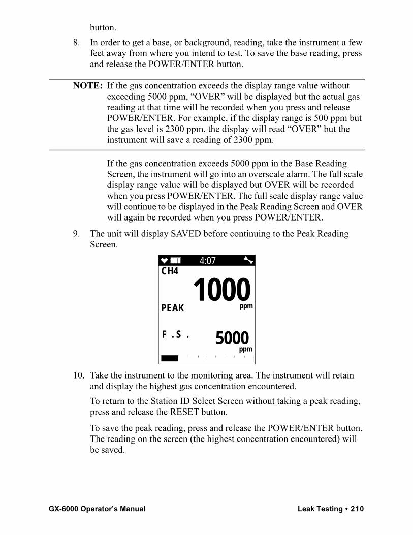
button.8. In order to get a base, or background, reading, take the instrument a few
feet away from where you intend to test. To save the base reading, press and release the POWER/ENTER button.
NOTE: If the gas concentration exceeds the display range value without exceeding 5000 ppm, “OVER” will be displayed but the actual gas reading at that time will be recorded when you press and release POWER/ENTER. For example, if the display range is 500 ppm but the gas level is 2300 ppm, the display will read “OVER” but the instrument will save a reading of 2300 ppm.
If the gas concentration exceeds 5000 ppm in the Base Reading Screen, the instrument will go into an overscale alarm. The full scale display range value will be displayed but OVER will be recorded when you press POWER/ENTER. The full scale display range value will continue to be displayed in the Peak Reading Screen and OVER will again be recorded when you press POWER/ENTER.
9. The unit will display SAVED before continuing to the Peak Reading Screen.
10. Take the instrument to the monitoring area. The instrument will retain and display the highest gas concentration encountered. To return to the Station ID Select Screen without taking a peak reading, press and release the RESET button.
To save the peak reading, press and release the POWER/ENTER button. The reading on the screen (the highest concentration encountered) will be saved.
4:07CH4
F . S .
1000
ppm
5000 ppm
PEAK
GX-6000 Operator’s Manual Leak Testing • 210
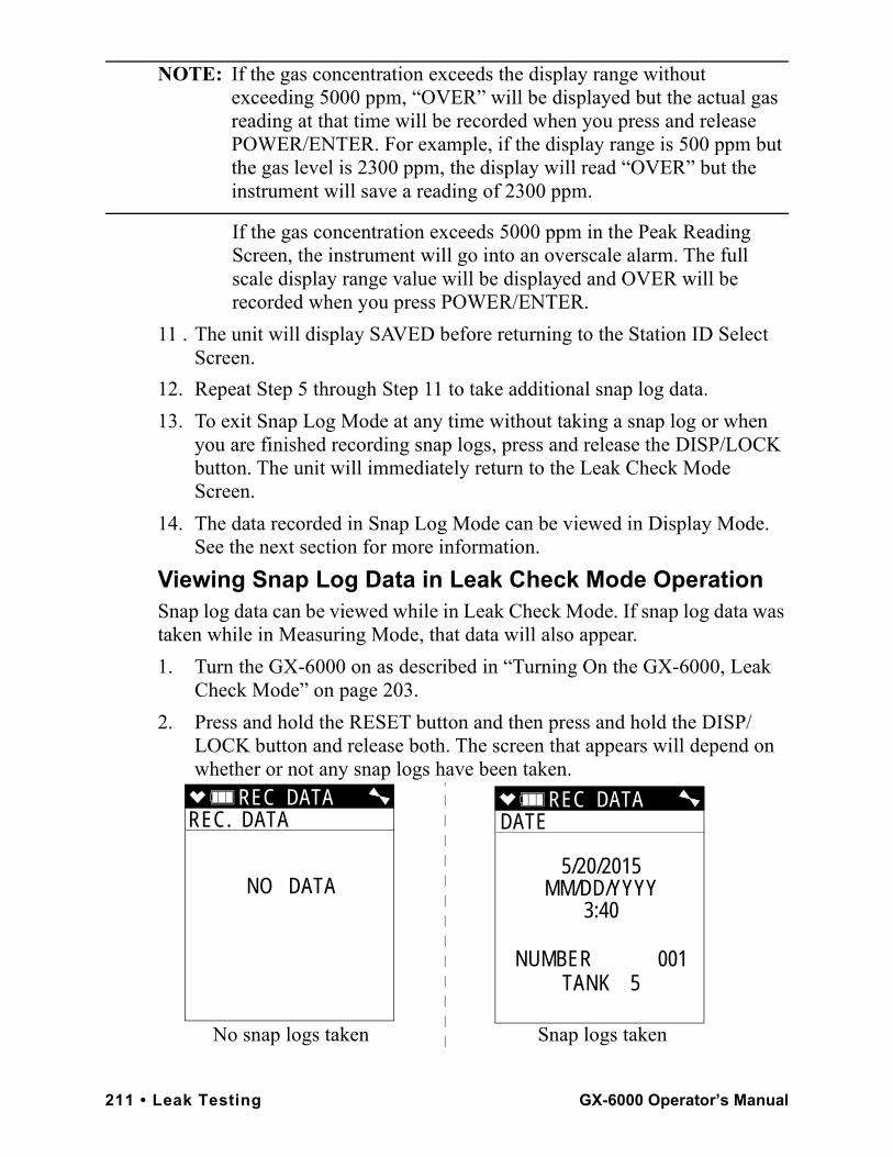
NOTE: If the gas concentration exceeds the display range without exceeding 5000 ppm, “OVER” will be displayed but the actual gas reading at that time will be recorded when you press and release POWER/ENTER. For example, if the display range is 500 ppm but the gas level is 2300 ppm, the display will read “OVER” but the instrument will save a reading of 2300 ppm.
If the gas concentration exceeds 5000 ppm in the Peak Reading Screen, the instrument will go into an overscale alarm. The full scale display range value will be displayed and OVER will be recorded when you press POWER/ENTER.
11 . The unit will display SAVED before returning to the Station ID Select Screen.
12. Repeat Step 5 through Step 11 to take additional snap log data.13. To exit Snap Log Mode at any time without taking a snap log or when
you are finished recording snap logs, press and release the DISP/LOCK button. The unit will immediately return to the Leak Check Mode Screen.
14. The data recorded in Snap Log Mode can be viewed in Display Mode. See the next section for more information.
Viewing Snap Log Data in Leak Check Mode OperationSnap log data can be viewed while in Leak Check Mode. If snap log data was taken while in Measuring Mode, that data will also appear.1. Turn the GX-6000 on as described in “Turning On the GX-6000, Leak
Check Mode” on page 203.2. Press and hold the RESET button and then press and hold the DISP/
LOCK button and release both. The screen that appears will depend on whether or not any snap logs have been taken.
REC DATA REC. DATA
NO DATA
REC DATA DATE
5/20/2015MM/DD/YYYY
3:40
NUMBER 001TANK 5
No snap logs taken Snap logs taken
211 • Leak Testing GX-6000 Operator’s Manual
3 . If snap logs have been taken, the screen indicates the year, month, day, and time that the most recent snap log was taken. The number near the bottom of the screen indicates the snap log ID number. The first snap log that is taken is given an ID of 001. The next snap log ID is 002. The ID number increases sequentially with each set of snap log data.
The last line of the screen indicates the Station ID that was used for the snap log.
4 . Press and release the DISP/LOCK button to return to Leak Check Mode.5 . Use the ▲AIR and SHIFT ▼ (PANIC) buttons to scroll through different
snap log IDs and view what time they were taken. Snap log data that was taken in Leak Check Mode operation will have two snap log ID numbers. One number is for the gas reading and the other is for the peak reading.
6. To view the data in a snap log ID, press and release the POWER/ENTER button. The gas readings that were taken during the snap log are displayed.
GX-6000 Operator’s Manual Leak Testing • 212
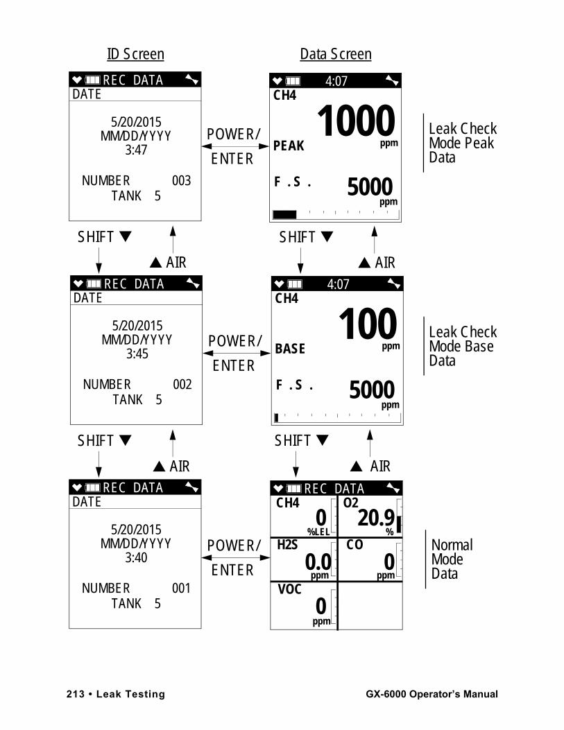
4:07CH4
F . S .
1000
ppm
5000 ppm
PEAK
REC DATA DATE
5/20/2015MM/DD/YYYY
3:47
NUMBER 003TANK 5
REC DATA DATE
5/20/2015MM/DD/YYYY
3:45
NUMBER 002TANK 5
REC DATA DATE
5/20/2015MM/DD/YYYY
3:40
NUMBER 001TANK 5
4:07CH4
F . S .
100
ppm
5000 ppm
BASE
REC DATA CH4 O2
%LEL % H2S CO
ppm ppm
VOC
ppm
0 20.9
0.0 0
0
POWER/
ENTER
POWER/
ENTER
POWER/
ENTER
SHIFT ▼
▲ AIR
SHIFT ▼
▲ AIR
Leak CheckMode PeakData
Leak Check Mode Base Data
NormalModeData
SHIFT ▼
▲ AIR
SHIFT ▼
▲ AIR
ID Screen Data Screen
213 • Leak Testing GX-6000 Operator’s Manual
Snap log data that was taken in Leak Check Mode operation will have 2 sequential screens that are part of one data set. One screen is for the base reading and the other screen is for the peak reading. “BASE” and “PEAK” will appear in the gas reading screen for each type of reading, respectively. If a base data point appears without a peak data point after it, it is because a peak data point was not taken.
NOTE: Even if CO DISPLAY was set to ON when the Leak Check snap logs were taken, the CO reading will not be displayed. The CO readings can be viewed using the GX-6000 Datalogging Program.
7 . Use the ▲AIR and SHIFT ▼ (PANIC) buttons to scroll through the different snap log data screens. The gas readings will change but the snap log ID is not visible from this screen.
8 . You can also go back and forth between the ID and data screens by pressing and releasing the POWER/ENTER button.
9 . To return to Leak Check Mode, press and release the DISP/LOCK button.
Turning Off the GX-6000, Leak Check Mode1 . Press and hold the POWER/ENTER button.2 . TURN OFF will appear on the display and the buzzer will pulse for
about five seconds.3 . Release the button when TURN OFF disappears from the display.
GX-6000 Operator’s Manual Leak Testing • 214
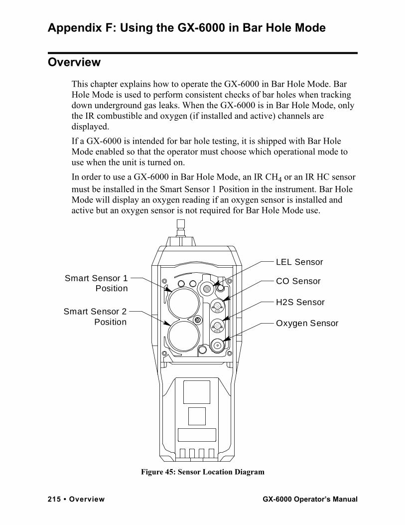
Appendix F: Using the GX-6000 in Bar Hole Mode
OverviewThis chapter explains how to operate the GX-6000 in Bar Hole Mode. Bar Hole Mode is used to perform consistent checks of bar holes when tracking down underground gas leaks. When the GX-6000 is in Bar Hole Mode, only the IR combustible and oxygen (if installed and active) channels are displayed.If a GX-6000 is intended for bar hole testing, it is shipped with Bar Hole Mode enabled so that the operator must choose which operational mode to use when the unit is turned on.In order to use a GX-6000 in Bar Hole Mode, an IR CH4 or an IR HC sensor must be installed in the Smart Sensor 1 Position in the instrument. Bar Hole Mode will display an oxygen reading if an oxygen sensor is installed and active but an oxygen sensor is not required for Bar Hole Mode use.
Figure 45: Sensor Location Diagram
CO Sensor
H2S Sensor
Oxygen SensorH2 S
CO
LEL Sensor
Smart Sensor 2 Position
Smart Sensor 1 Position
215 • Overview GX-6000 Operator’s Manual
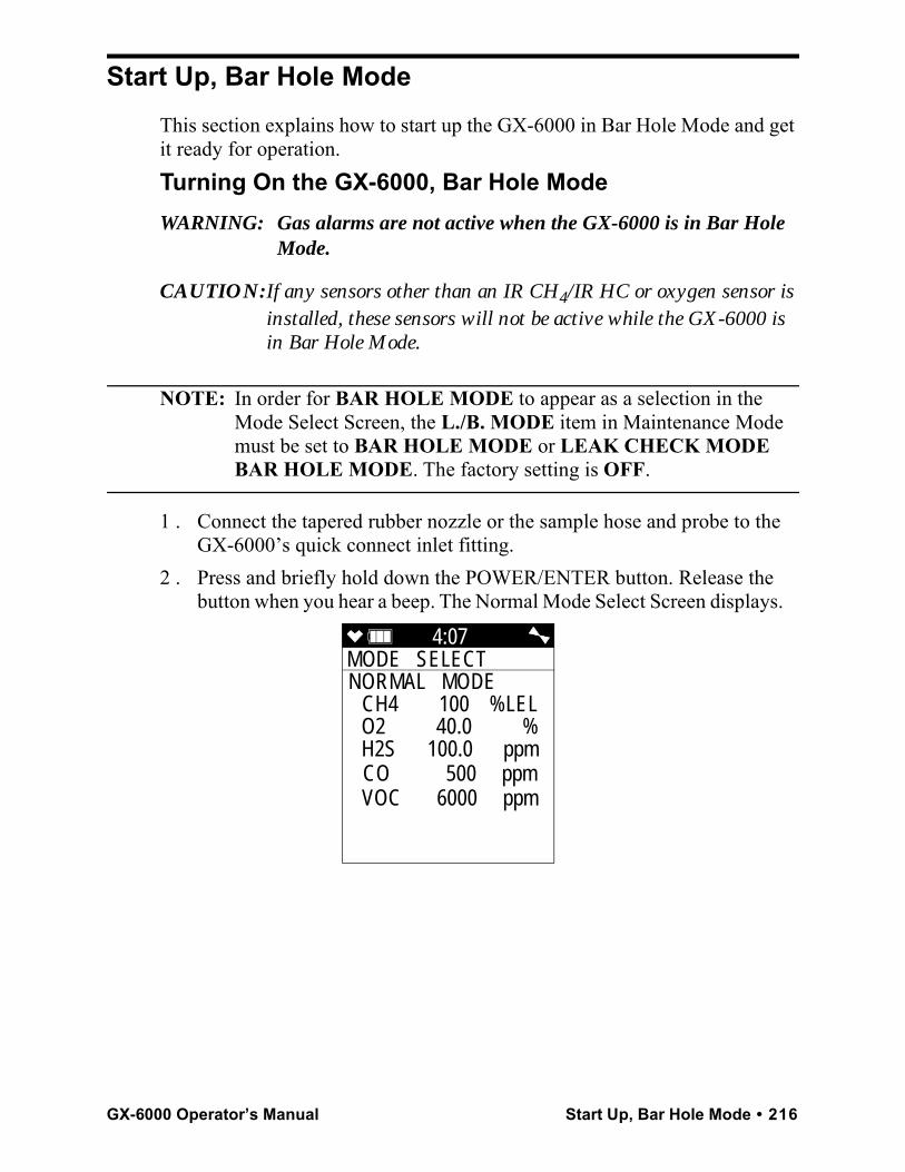
Start Up, Bar Hole ModeThis section explains how to start up the GX-6000 in Bar Hole Mode and get it ready for operation.Turning On the GX-6000, Bar Hole ModeWARNING: Gas alarms are not active when the GX-6000 is in Bar Hole
Mode.
CAUTION: If any sensors other than an IR CH4/IR HC or oxygen sensor is installed, these sensors will not be active while the GX-6000 is in Bar Hole Mode.
NOTE: In order for BAR HOLE MODE to appear as a selection in the Mode Select Screen, the L./B. MODE item in Maintenance Mode must be set to BAR HOLE MODE or LEAK CHECK MODE BAR HOLE MODE. The factory setting is OFF.
1 . Connect the tapered rubber nozzle or the sample hose and probe to the GX-6000’s quick connect inlet fitting.
2 . Press and briefly hold down the POWER/ENTER button. Release the button when you hear a beep. The Normal Mode Select Screen displays.
4:07MODE SELECT NORMAL MODE
CH4 100 %LELO2 40.0 %H2S 100.0 ppmCO 500 ppmVOC 6000 ppm
GX-6000 Operator’s Manual Start Up, Bar Hole Mode • 216
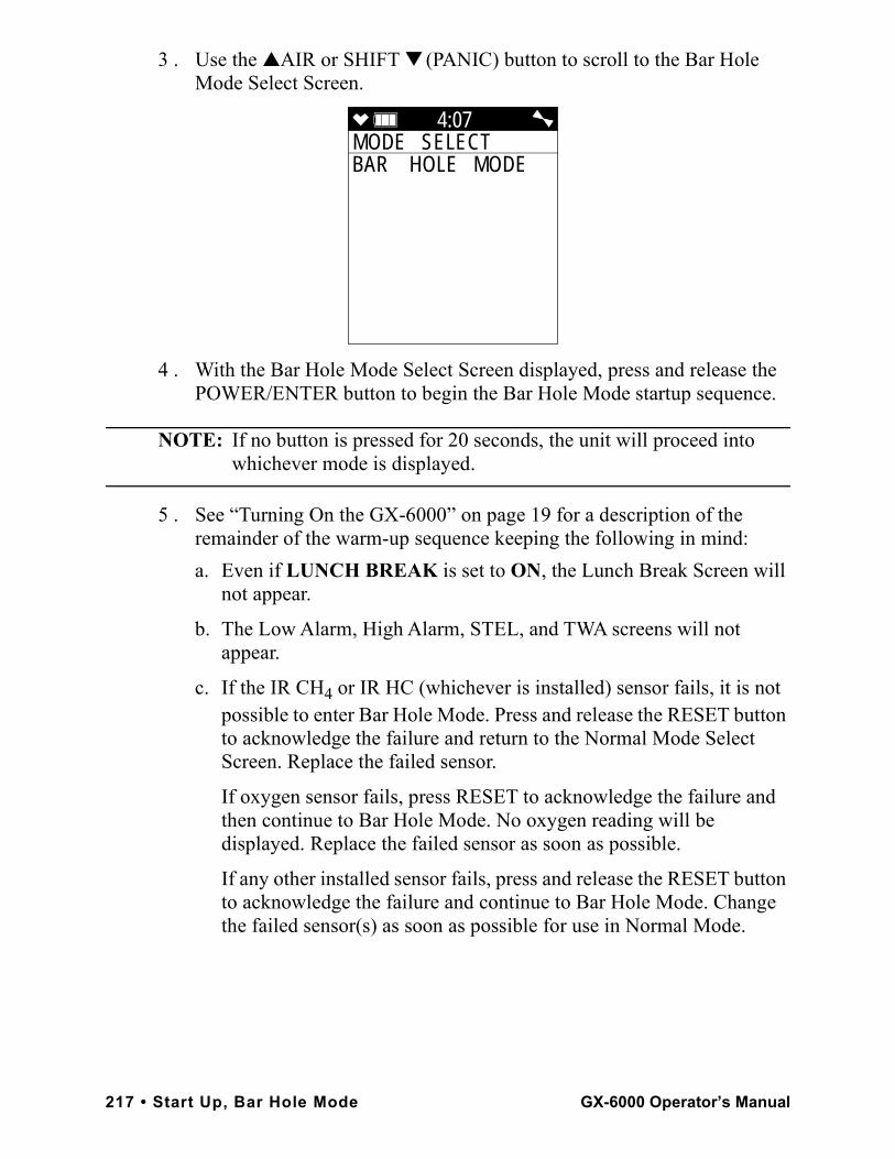
3 . Use the ▲AIR or SHIFT ▼ (PANIC) button to scroll to the Bar Hole Mode Select Screen.
4 . With the Bar Hole Mode Select Screen displayed, press and release the POWER/ENTER button to begin the Bar Hole Mode startup sequence.
NOTE: If no button is pressed for 20 seconds, the unit will proceed into whichever mode is displayed.
5 . See “Turning On the GX-6000” on page 19 for a description of the remainder of the warm-up sequence keeping the following in mind:
a. Even if LUNCH BREAK is set to ON, the Lunch Break Screen will not appear.
b. The Low Alarm, High Alarm, STEL, and TWA screens will not appear.
c. If the IR CH4 or IR HC (whichever is installed) sensor fails, it is not possible to enter Bar Hole Mode. Press and release the RESET button to acknowledge the failure and return to the Normal Mode Select Screen. Replace the failed sensor.
If oxygen sensor fails, press RESET to acknowledge the failure and then continue to Bar Hole Mode. No oxygen reading will be displayed. Replace the failed sensor as soon as possible.
If any other installed sensor fails, press and release the RESET button to acknowledge the failure and continue to Bar Hole Mode. Change the failed sensor(s) as soon as possible for use in Normal Mode.
4:07MODE SELECT BAR HOLE MODE
217 • Start Up, Bar Hole Mode GX-6000 Operator’s Manual
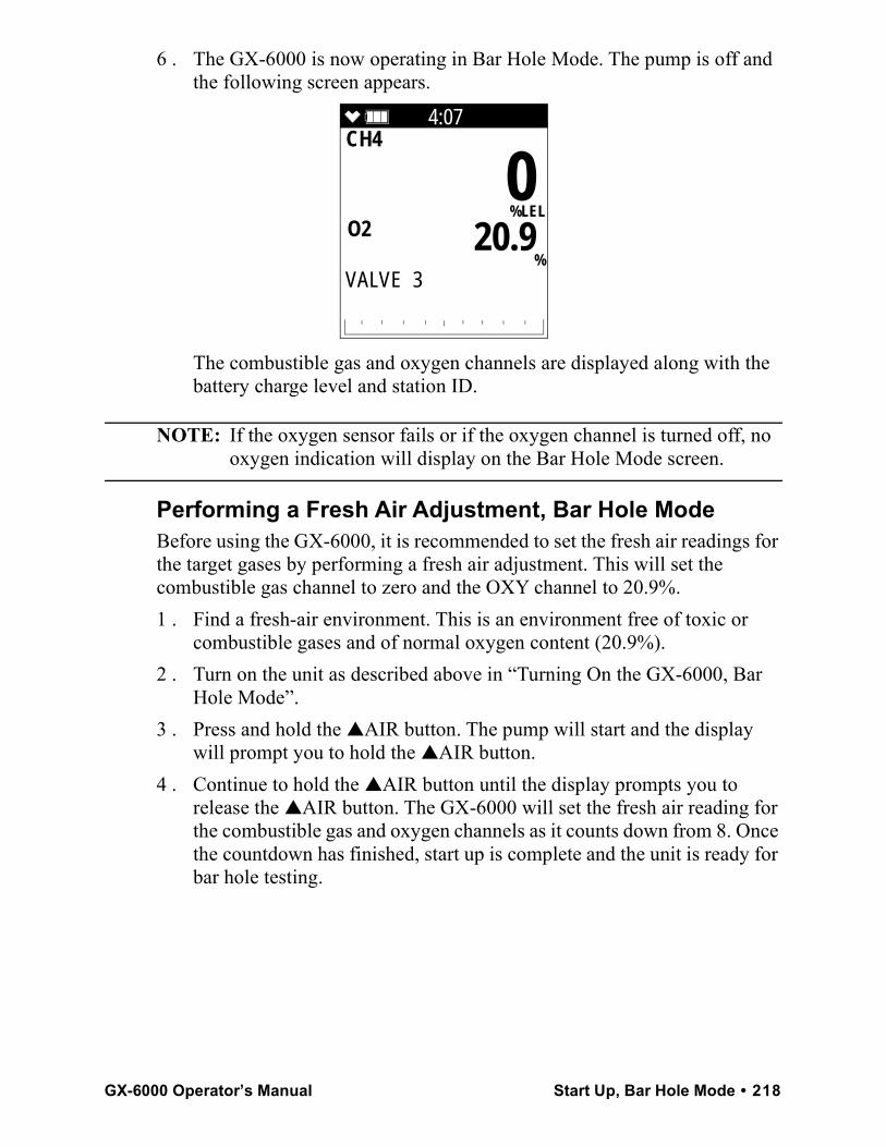
6 . The GX-6000 is now operating in Bar Hole Mode. The pump is off and the following screen appears.
The combustible gas and oxygen channels are displayed along with the battery charge level and station ID.
NOTE: If the oxygen sensor fails or if the oxygen channel is turned off, no oxygen indication will display on the Bar Hole Mode screen.
Performing a Fresh Air Adjustment, Bar Hole ModeBefore using the GX-6000, it is recommended to set the fresh air readings for the target gases by performing a fresh air adjustment. This will set the combustible gas channel to zero and the OXY channel to 20.9%.1 . Find a fresh-air environment. This is an environment free of toxic or
combustible gases and of normal oxygen content (20.9%).2 . Turn on the unit as described above in “Turning On the GX-6000, Bar
Hole Mode”.3 . Press and hold the ▲AIR button. The pump will start and the display
will prompt you to hold the ▲AIR button. 4 . Continue to hold the ▲AIR button until the display prompts you to
release the ▲AIR button. The GX-6000 will set the fresh air reading for the combustible gas and oxygen channels as it counts down from 8. Once the countdown has finished, start up is complete and the unit is ready for bar hole testing.
4:07CH4
O2
0
%LEL
20.9 %
VALVE 3
GX-6000 Operator’s Manual Start Up, Bar Hole Mode • 218
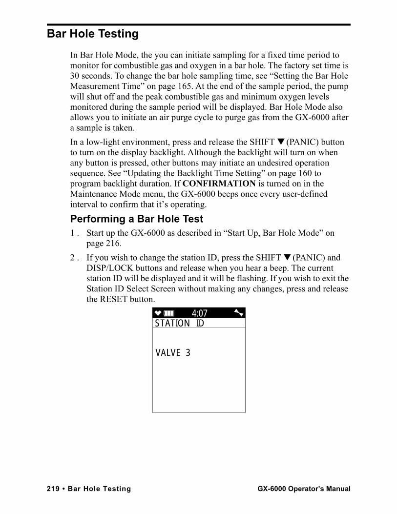
Bar Hole TestingIn Bar Hole Mode, the you can initiate sampling for a fixed time period to monitor for combustible gas and oxygen in a bar hole. The factory set time is 30 seconds. To change the bar hole sampling time, see “Setting the Bar Hole Measurement Time” on page 165. At the end of the sample period, the pump will shut off and the peak combustible gas and minimum oxygen levels monitored during the sample period will be displayed. Bar Hole Mode also allows you to initiate an air purge cycle to purge gas from the GX-6000 after a sample is taken. In a low-light environment, press and release the SHIFT ▼ (PANIC) button to turn on the display backlight. Although the backlight will turn on when any button is pressed, other buttons may initiate an undesired operation sequence. See “Updating the Backlight Time Setting” on page 160 to program backlight duration. If CONFIRMATION is turned on in the Maintenance Mode menu, the GX-6000 beeps once every user-defined interval to confirm that it’s operating.Performing a Bar Hole Test1 . Start up the GX-6000 as described in “Start Up, Bar Hole Mode” on
page 216.2 . If you wish to change the station ID, press the SHIFT ▼ (PANIC) and
DISP/LOCK buttons and release when you hear a beep. The current station ID will be displayed and it will be flashing. If you wish to exit the Station ID Select Screen without making any changes, press and release the RESET button.
4:07STATION ID
VALVE 3
219 • Bar Hole Testing GX-6000 Operator’s Manual
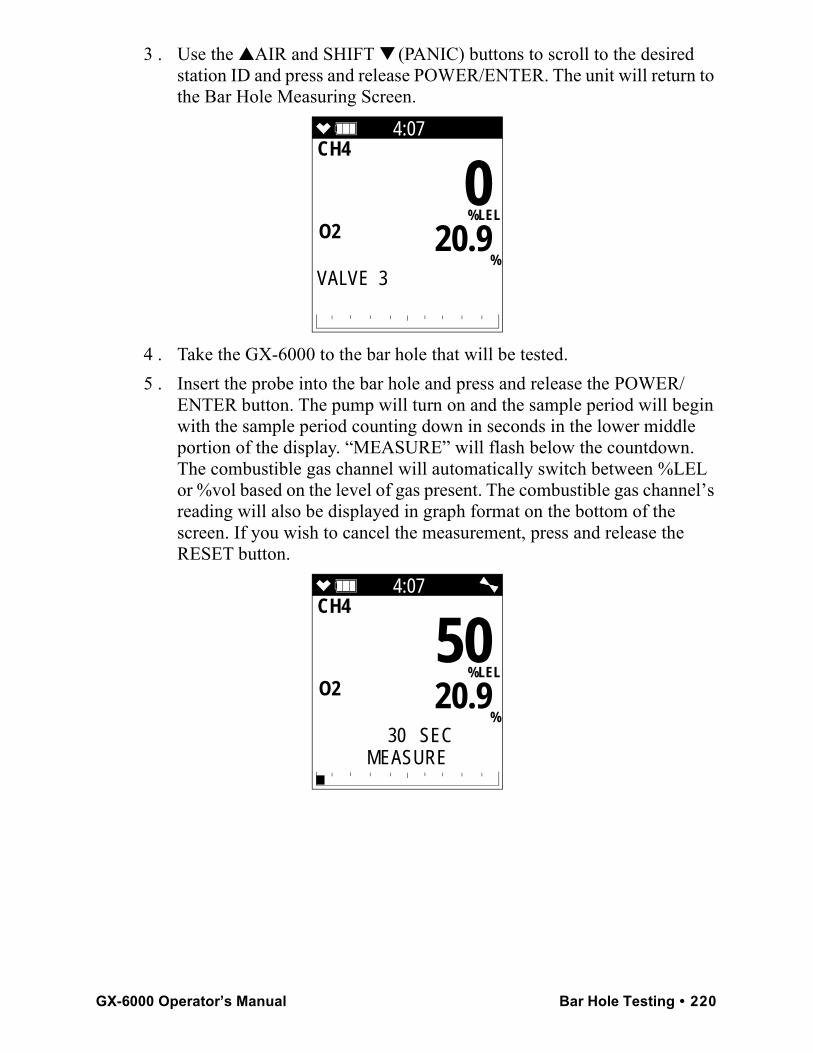
3 . Use the ▲AIR and SHIFT ▼ (PANIC) buttons to scroll to the desired station ID and press and release POWER/ENTER. The unit will return to the Bar Hole Measuring Screen.
4 . Take the GX-6000 to the bar hole that will be tested.5 . Insert the probe into the bar hole and press and release the POWER/
ENTER button. The pump will turn on and the sample period will begin with the sample period counting down in seconds in the lower middle portion of the display. “MEASURE” will flash below the countdown. The combustible gas channel will automatically switch between %LEL or %vol based on the level of gas present. The combustible gas channel’s reading will also be displayed in graph format on the bottom of the screen. If you wish to cancel the measurement, press and release the RESET button.
4:07CH4
O2
0
%LEL
20.9 %
VALVE 3
4:07CH4
O2
50
%LEL
20.9 %
30 SECMEASURE
GX-6000 Operator’s Manual Bar Hole Testing • 220
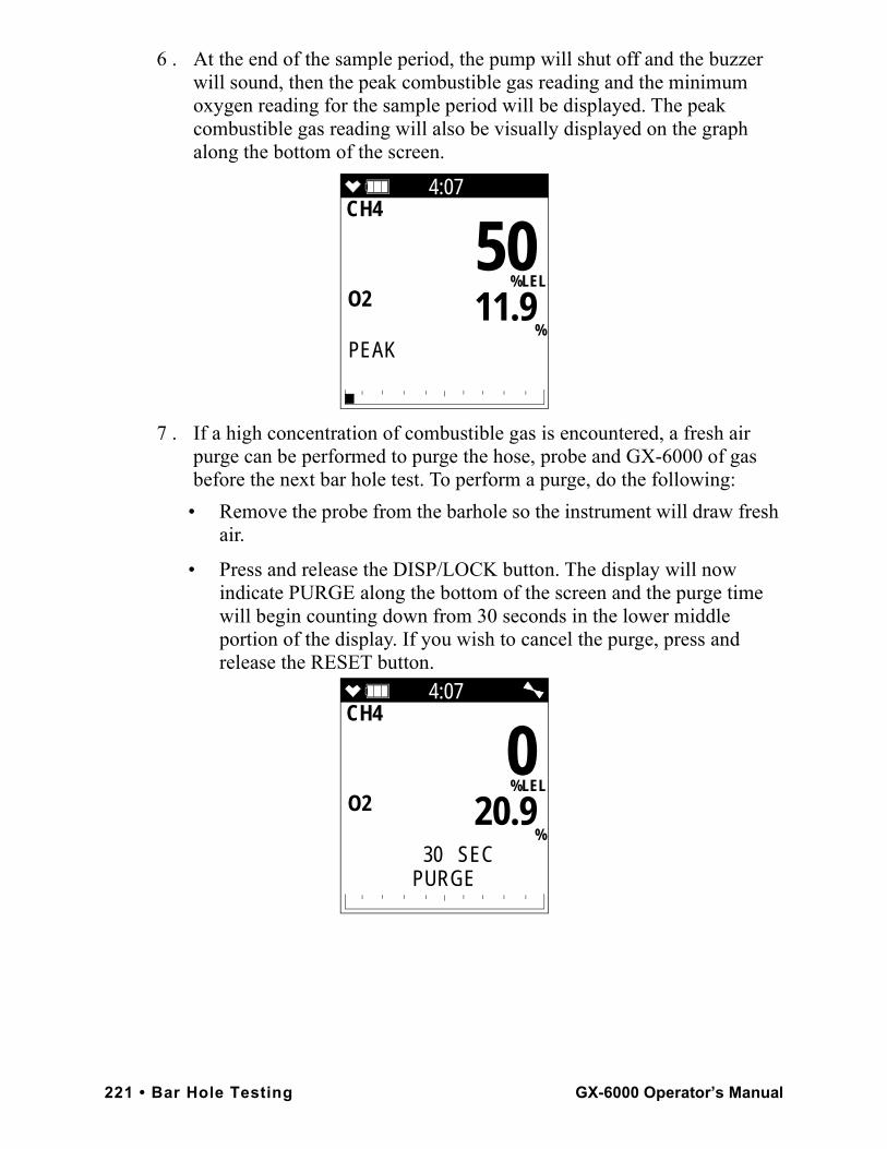
6 . At the end of the sample period, the pump will shut off and the buzzer will sound, then the peak combustible gas reading and the minimum oxygen reading for the sample period will be displayed. The peak combustible gas reading will also be visually displayed on the graph along the bottom of the screen.
7 . If a high concentration of combustible gas is encountered, a fresh air purge can be performed to purge the hose, probe and GX-6000 of gas before the next bar hole test. To perform a purge, do the following:
• Remove the probe from the barhole so the instrument will draw fresh air.
• Press and release the DISP/LOCK button. The display will now indicate PURGE along the bottom of the screen and the purge time will begin counting down from 30 seconds in the lower middle portion of the display. If you wish to cancel the purge, press and release the RESET button.
4:07CH4
O2
50
%LEL
11.9 %
PEAK
4:07CH4
O2
0
%LEL
20.9 %
30 SECPURGE
221 • Bar Hole Testing GX-6000 Operator’s Manual
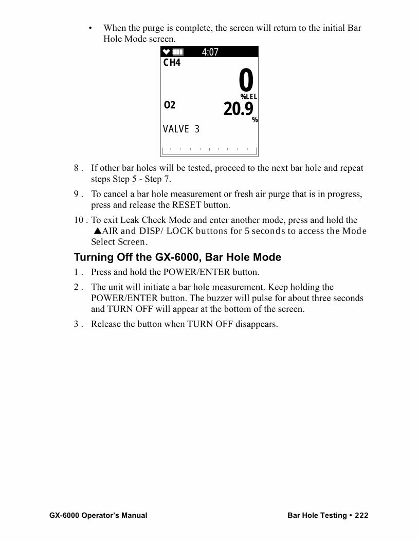
• When the purge is complete, the screen will return to the initial Bar Hole Mode screen.
8 . If other bar holes will be tested, proceed to the next bar hole and repeat steps Step 5 - Step 7.
9 . To cancel a bar hole measurement or fresh air purge that is in progress, press and release the RESET button.
10 . To exit Leak Check Mode and enter another mode, press and hold the ▲AIR and DISP/LOCK buttons for 5 seconds to access the Mode Select Screen.
Turning Off the GX-6000, Bar Hole Mode1 . Press and hold the POWER/ENTER button.2 . The unit will initiate a bar hole measurement. Keep holding the
POWER/ENTER button. The buzzer will pulse for about three seconds and TURN OFF will appear at the bottom of the screen.
3 . Release the button when TURN OFF disappears.
4:07CH4
O2
0
%LEL
20.9 %
VALVE 3
GX-6000 Operator’s Manual Bar Hole Testing • 222
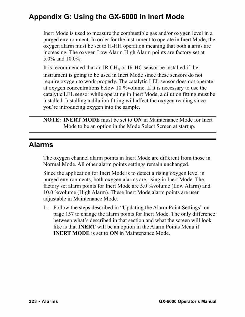
Appendix G: Using the GX-6000 in Inert Mode
Inert Mode is used to measure the combustible gas and/or oxygen level in a purged environment. In order for the instrument to operate in Inert Mode, the oxygen alarm must be set to H-HH operation meaning that both alarms are increasing. The oxygen Low Alarm High Alarm points are factory set at 5.0% and 10.0%. It is recommended that an IR CH4 or IR HC sensor be installed if the instrument is going to be used in Inert Mode since these sensors do not require oxygen to work properly. The catalytic LEL sensor does not operate at oxygen concentrations below 10 %volume. If it is necessary to use the catalytic LEL sensor while operating in Inert Mode, a dilution fitting must be installed. Installing a dilution fitting will affect the oxygen reading since you’re introducing oxygen into the sample.
NOTE: INERT MODE must be set to ON in Maintenance Mode for Inert Mode to be an option in the Mode Select Screen at startup.
AlarmsThe oxygen channel alarm points in Inert Mode are different from those in Normal Mode. All other alarm points settings remain unchanged.Since the application for Inert Mode is to detect a rising oxygen level in purged environments, both oxygen alarms are rising in Inert Mode. The factory set alarm points for Inert Mode are 5.0 %volume (Low Alarm) and 10.0 %volume (High Alarm). These Inert Mode alarm points are user adjustable in Maintenance Mode.1 . Follow the steps described in “Updating the Alarm Point Settings” on
page 157 to change the alarm points for Inert Mode. The only difference between what’s described in that section and what the screen will look like is that INERT will be an option in the Alarm Points Menu if INERT MODE is set to ON in Maintenance Mode.
223 • Alarms GX-6000 Operator’s Manual
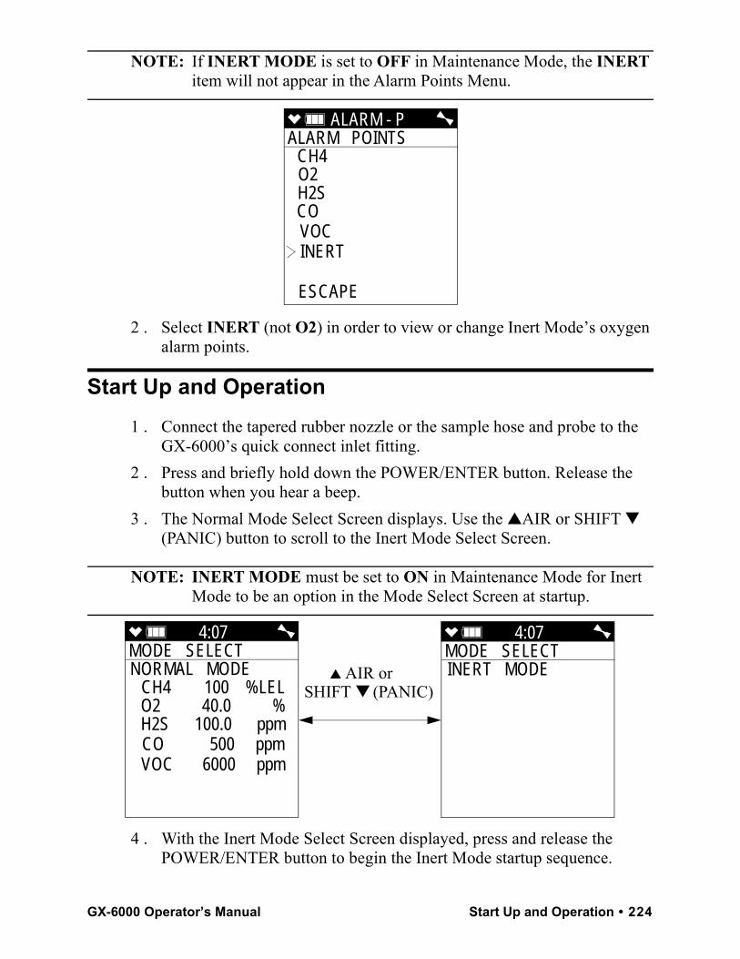
NOTE: If INERT MODE is set to OFF in Maintenance Mode, the INERT item will not appear in the Alarm Points Menu.
2 . Select INERT (not O2) in order to view or change Inert Mode’s oxygen alarm points.
Start Up and Operation1 . Connect the tapered rubber nozzle or the sample hose and probe to the
GX-6000’s quick connect inlet fitting.2 . Press and briefly hold down the POWER/ENTER button. Release the
button when you hear a beep.3 . The Normal Mode Select Screen displays. Use the ▲AIR or SHIFT ▼
(PANIC) button to scroll to the Inert Mode Select Screen.
NOTE: INERT MODE must be set to ON in Maintenance Mode for Inert Mode to be an option in the Mode Select Screen at startup.
4 . With the Inert Mode Select Screen displayed, press and release the POWER/ENTER button to begin the Inert Mode startup sequence.
ALARM - P ALARM POINTS
CH4 O2 H2S CO VOC INERT
ESCAPE
4:07MODE SELECT NORMAL MODE
CH4 100 %LELO2 40.0 %H2S 100.0 ppmCO 500 ppmVOC 6000 ppm
4:07MODE SELECT INERT MODE
▲ AIR or SHIFT ▼ (PANIC)
GX-6000 Operator’s Manual Start Up and Operation • 224
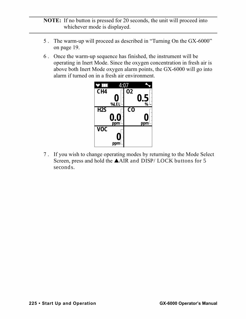
NOTE: If no button is pressed for 20 seconds, the unit will proceed into whichever mode is displayed.
5 . The warm-up will proceed as described in “Turning On the GX-6000” on page 19.
6 . Once the warm-up sequence has finished, the instrument will be operating in Inert Mode. Since the oxygen concentration in fresh air is above both Inert Mode oxygen alarm points, the GX-6000 will go into alarm if turned on in a fresh air environment.
7 . If you wish to change operating modes by returning to the Mode Select Screen, press and hold the ▲AIR and DISP/LOCK buttons for 5 seconds.
4:07CH4 O2
%LEL % H2S CO
ppm ppm
VOC
ppm
0 0.5
0.0 0
0
225 • Start Up and Operation GX-6000 Operator’s Manual
Appendix H: 10.0 eV/Benzene PID Sensor
OverviewThis appendix describes the GX-6000’s 10.0 eV/benzene sensor (RKI part number PID-003L).The 10.0 eV/benzene PID sensor detects VOCs in the 0-100.00 ppm range when used in Measuring Mode. It is optimized for benzene detection. The standard calibration for the 10.0 eV/benzene PID sensor is to benzene but it can be factory setup for and calibrated to other gases. Regardless of the calibration gas, the 10.0 eV/benzene sensor will still detect and respond to a variety of volatile organic compounds (VOCs) while used in Measuring Mode. Even though the 10.0 eV/benzene sensor can be used for general VOC detection, if your application is for general VOC detection and is not related to monitoring for benzene specifically, RKI Instruments, Inc. recommends that the low range or high range 10.6 eV PID sensor be used instead.The 10.0 eV/benzene PID sensor detects VOCs in the 0-50.00 ppm range when used in Benzene Select Mode. The filter tube that needs to be used in Benzene Select Mode allows benzene to pass through but scrubs out all other VOCs except for nitrobenzene, cyclohexane, n-octane, and n-pentane. Common applications for the 10.0 eV/benzene PID sensor include process monitoring where only benzene is present or petroleum industry monitoring where other VOCs may be present.See the table below for 10.0 eV/benzene sensor specifications.
Table 28: 10.0 eV/Benzene PID Sensor Specifications
Measuring Mode Operation
Benzene Select Mode Operation
Detection Range 0 - 100.00 ppm 0 - 50.00 ppm
Reading Increment 0 - 10 ppm: 0.01 ppm10 - 100 ppm: 0.1 ppm
0 - 10 ppm: 0.01 ppm10 - 50 ppm: 0.1 ppm
Alarm 1Factory Setting
5 ppm N/A
Alarm 2Factory Setting
10 ppm N/A
STEL Alarm N/A N/A
TWA Alarm N/A N/A
GX-6000 Operator’s Manual Overview • 226
Sensor DescriptionThe PID sensor is a cylindrical sensor with a diffusion opening on the front and 3 pins on the back. It is installed in a white housing that has three sockets on the bottom that mate with the GX-6000 instrument. The PID sensor must always be installed in the first smart sensor position which is located in the top left corner of the sensor block.
Tube and Tube HolderBenzene detection typically requires the use of a filter tube. The filter tube will scrub out most VOCs other than benzene but will not scrub out nitrobenzene, cyclohexane, n-octane, or n-pentane. The filter tube is installed in a tube holder and needs to be replaced regularly. A tube holder and a box of tubes are included with 10.0 eV/benzene versions of the GX-6000. TubeEach tube has a 3/4 line on it. If the tube becomes discolored and if the discoloration extends beyond the 3/4 line, the tube is no longer effectively scrubbing non-benzene gases and needs to be replaced.Tubes must be stored in a cool, dark place (0 - 25 °C/ 32 - 77 °F) and must be used before the expiration date that is printed on the box. If the tubes are being stored in a refrigerator, take them out of the refrigerator and let them sit overnight before using them.Tubes do not contain cadmium, mercury, or chrome and may be disposed as general waste.
227 • Sensor Description GX-6000 Operator’s Manual
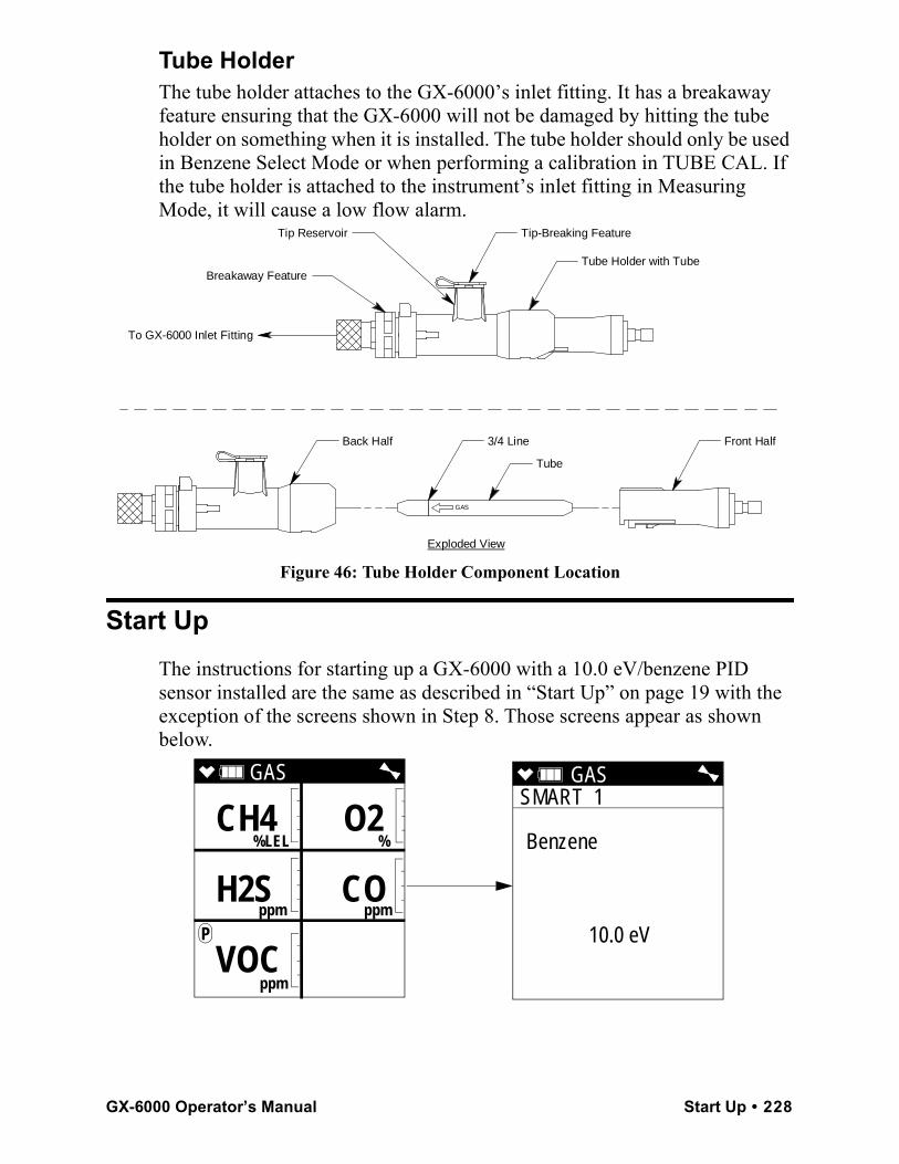
Tube HolderThe tube holder attaches to the GX-6000’s inlet fitting. It has a breakaway feature ensuring that the GX-6000 will not be damaged by hitting the tube holder on something when it is installed. The tube holder should only be used in Benzene Select Mode or when performing a calibration in TUBE CAL. If the tube holder is attached to the instrument’s inlet fitting in Measuring Mode, it will cause a low flow alarm.
Figure 46: Tube Holder Component Location
Start UpThe instructions for starting up a GX-6000 with a 10.0 eV/benzene PID sensor installed are the same as described in “Start Up” on page 19 with the exception of the screens shown in Step 8. Those screens appear as shown below.
Exploded View
To GX-6000 Inlet Fitting
Tip Reservoir
Breakaway Feature
GAS
Tube
3/4 LineBack Half Front Half
Tip-Breaking Feature
Tube Holder with Tube
GAS SMART 1
Benzene
10.0 eV
GAS
%LEL %
ppm ppm
P
ppm
CH4 O2
H2S CO
VOC
GX-6000 Operator’s Manual Start Up • 228
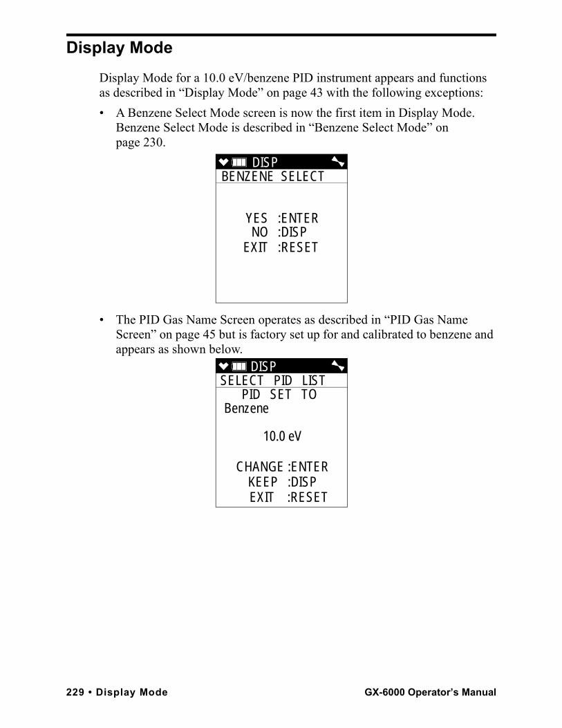
Display ModeDisplay Mode for a 10.0 eV/benzene PID instrument appears and functions as described in “Display Mode” on page 43 with the following exceptions:• A Benzene Select Mode screen is now the first item in Display Mode.
Benzene Select Mode is described in “Benzene Select Mode” on page 230.
• The PID Gas Name Screen operates as described in “PID Gas Name Screen” on page 45 but is factory set up for and calibrated to benzene and appears as shown below.
DISP BENZENE SELECT
YES :ENTERNO :DISP
EXIT :RESET
DISP SELECT PID LIST
PID SET TO Benzene
10.0 eV
CHANGE :ENTERKEEP :DISP
EXIT :RESET
229 • Display Mode GX-6000 Operator’s Manual
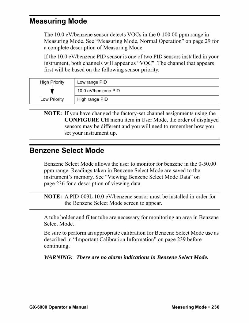
Measuring ModeThe 10.0 eV/benzene sensor detects VOCs in the 0-100.00 ppm range in Measuring Mode. See “Measuring Mode, Normal Operation” on page 29 for a complete description of Measuring Mode.If the 10.0 eV/benzene PID sensor is one of two PID sensors installed in your instrument, both channels will appear as “VOC”. The channel that appears first will be based on the following sensor priority.
NOTE: If you have changed the factory-set channel assignments using the CONFIGURE CH menu item in User Mode, the order of displayed sensors may be different and you will need to remember how you set your instrument up.
Benzene Select ModeBenzene Select Mode allows the user to monitor for benzene in the 0-50.00 ppm range. Readings taken in Benzene Select Mode are saved to the instrument’s memory. See “Viewing Benzene Select Mode Data” on page 236 for a description of viewing data.
NOTE: A PID-003L 10.0 eV/benzene sensor must be installed in order for the Benzene Select Mode screen to appear.
A tube holder and filter tube are necessary for monitoring an area in Benzene Select Mode.Be sure to perform an appropriate calibration for Benzene Select Mode use as described in “Important Calibration Information” on page 239 before continuing.
WARNING: There are no alarm indications in Benzene Select Mode.
High Priority
Low Priority
Low range PID
10.0 eV/benzene PID
High range PID
GX-6000 Operator’s Manual Measuring Mode • 230
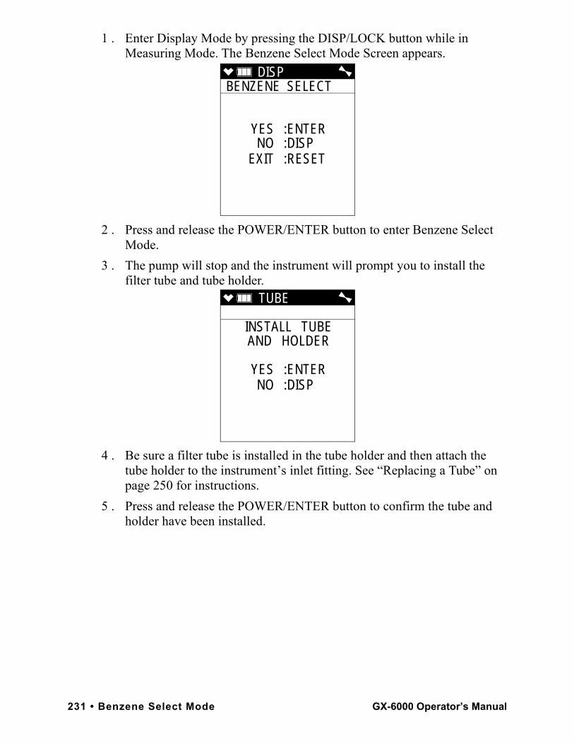
1 . Enter Display Mode by pressing the DISP/LOCK button while in Measuring Mode. The Benzene Select Mode Screen appears.
2 . Press and release the POWER/ENTER button to enter Benzene Select Mode.
3 . The pump will stop and the instrument will prompt you to install the filter tube and tube holder.
4 . Be sure a filter tube is installed in the tube holder and then attach the tube holder to the instrument’s inlet fitting. See “Replacing a Tube” on page 250 for instructions.
5 . Press and release the POWER/ENTER button to confirm the tube and holder have been installed.
DISP BENZENE SELECT
YES :ENTERNO :DISP
EXIT :RESET
TUBE
INSTALL TUBEAND HOLDER
YES :ENTERNO :DISP
231 • Benzene Select Mode GX-6000 Operator’s Manual
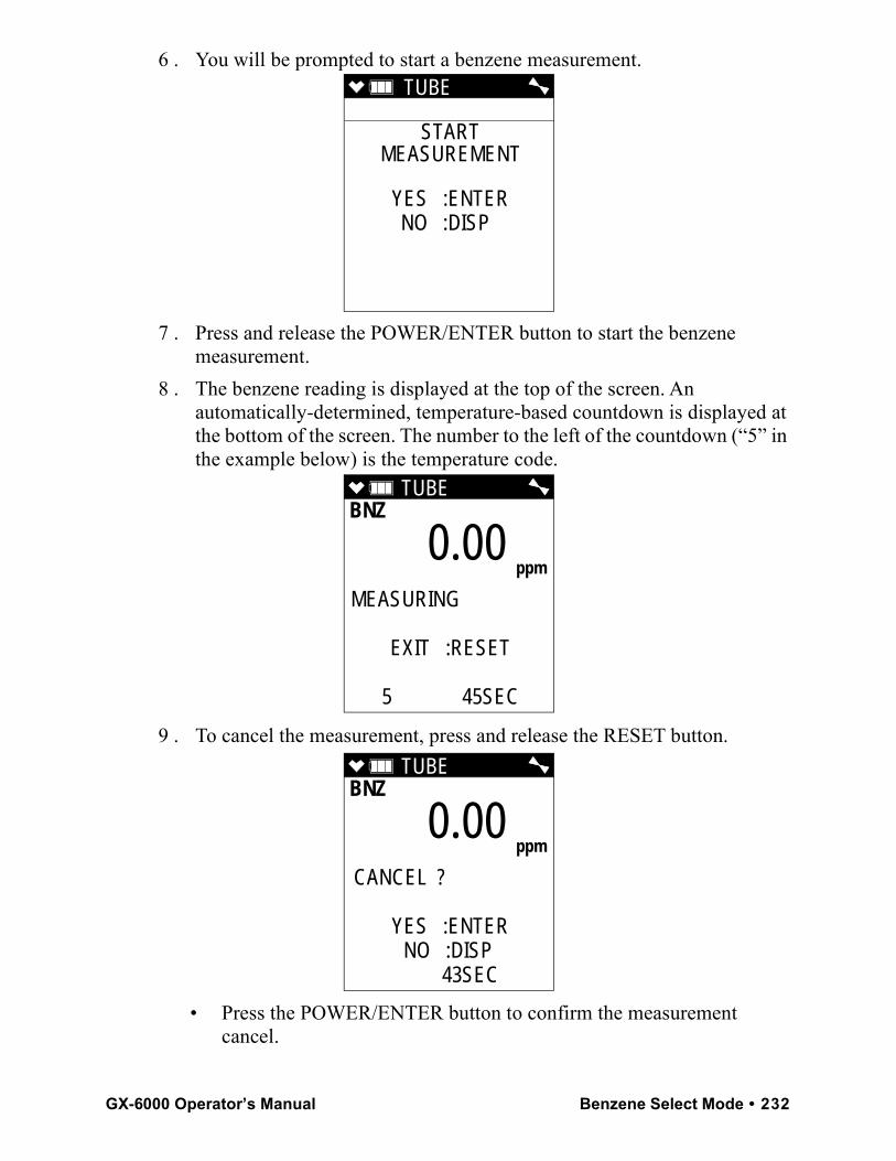
6 . You will be prompted to start a benzene measurement.
7 . Press and release the POWER/ENTER button to start the benzene measurement.
8 . The benzene reading is displayed at the top of the screen. An automatically-determined, temperature-based countdown is displayed at the bottom of the screen. The number to the left of the countdown (“5” in the example below) is the temperature code.
9 . To cancel the measurement, press and release the RESET button.
• Press the POWER/ENTER button to confirm the measurement cancel.
TUBE
STARTMEASUREMENT
YES :ENTERNO :DISP
TUBE BNZ
MEASURING
EXIT :RESET
5 45SEC
0.00 ppm
TUBE BNZ
CANCEL ?
YES :ENTERNO :DISP 43SEC
0.00 ppm
GX-6000 Operator’s Manual Benzene Select Mode • 232
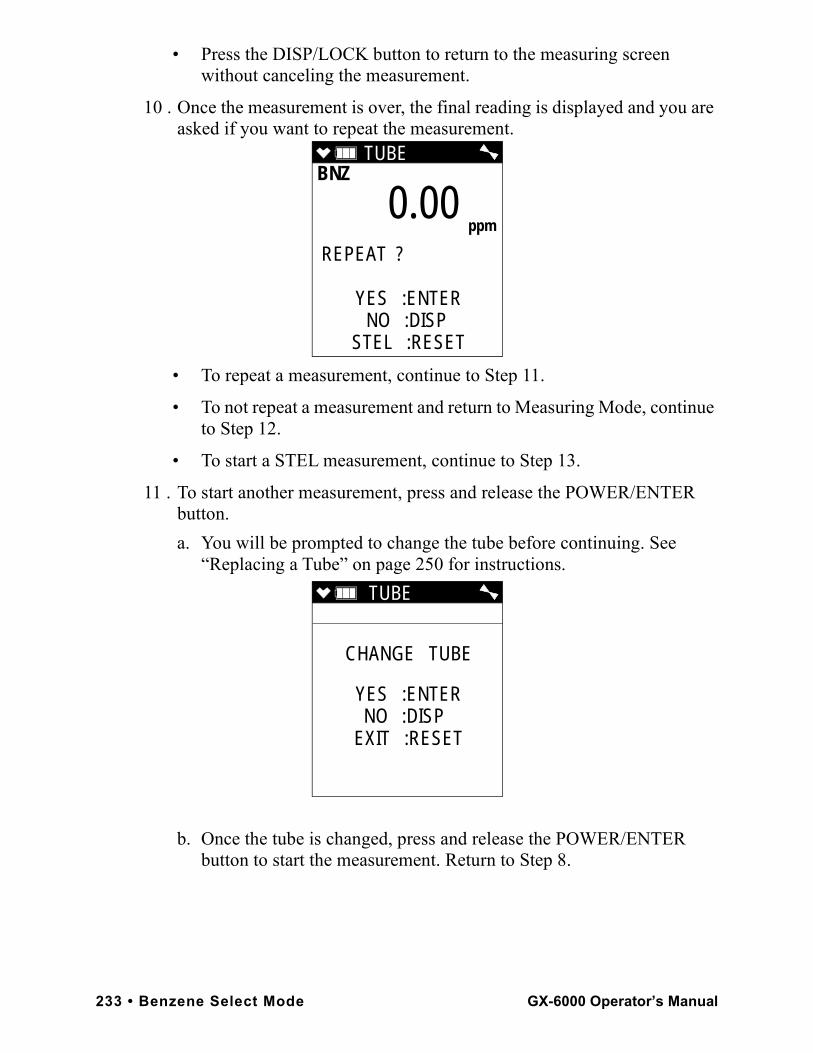
• Press the DISP/LOCK button to return to the measuring screen without canceling the measurement.
10 . Once the measurement is over, the final reading is displayed and you are asked if you want to repeat the measurement.
• To repeat a measurement, continue to Step 11.
• To not repeat a measurement and return to Measuring Mode, continue to Step 12.
• To start a STEL measurement, continue to Step 13.
11 . To start another measurement, press and release the POWER/ENTER button.
a. You will be prompted to change the tube before continuing. See “Replacing a Tube” on page 250 for instructions.
b. Once the tube is changed, press and release the POWER/ENTER button to start the measurement. Return to Step 8.
TUBE BNZ
REPEAT ?
YES :ENTERNO :DISP
STEL :RESET
0.00 ppm
TUBE
CHANGE TUBE
YES :ENTERNO :DISP
EXIT :RESET
233 • Benzene Select Mode GX-6000 Operator’s Manual
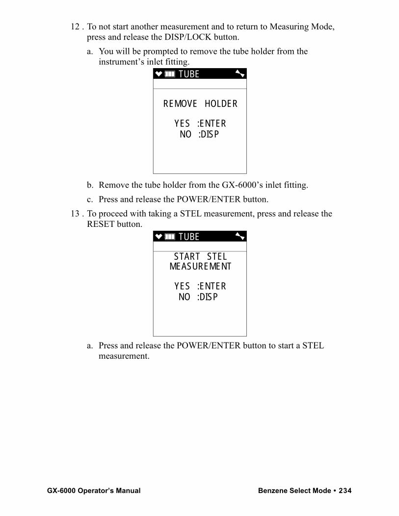
12 . To not start another measurement and to return to Measuring Mode, press and release the DISP/LOCK button.
a. You will be prompted to remove the tube holder from the instrument’s inlet fitting.
b. Remove the tube holder from the GX-6000’s inlet fitting. c. Press and release the POWER/ENTER button.
13 . To proceed with taking a STEL measurement, press and release the RESET button.
a. Press and release the POWER/ENTER button to start a STEL measurement.
TUBE
REMOVE HOLDER
YES :ENTERNO :DISP
TUBE
START STELMEASUREMENT
YES :ENTERNO :DISP
GX-6000 Operator’s Manual Benzene Select Mode • 234
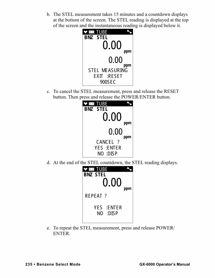
b. The STEL measurement takes 15 minutes and a countdown displays at the bottom of the screen. The STEL reading is displayed at the top of the screen and the instantaneous reading is displayed below it.
c. To cancel the STEL measurement, press and release the RESET button. Then press and release the POWER/ENTER button.
d. At the end of the STEL countdown, the STEL reading displays.
e. To repeat the STEL measurement, press and release POWER/ENTER.
TUBE BNZ STEL
STEL MEASURINGEXIT :RESET
900SEC
0.00 ppm
ppm0.00
TUBE BNZ STEL
CANCEL ?YES :ENTER
NO :DISP
0.00 ppm
ppm0.00
TUBE BNZ STEL
REPEAT ?
YES :ENTERNO :DISP
0.00 ppm
235 • Benzene Select Mode GX-6000 Operator’s Manual
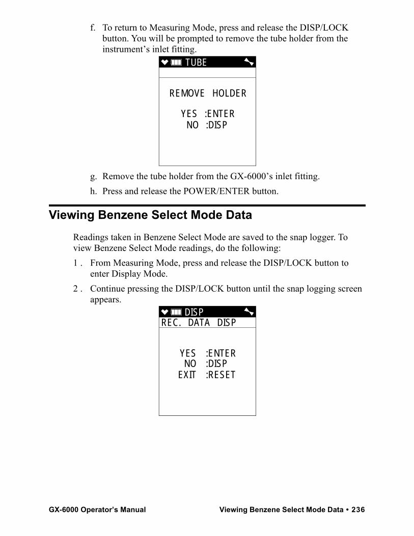
f. To return to Measuring Mode, press and release the DISP/LOCK button. You will be prompted to remove the tube holder from the instrument’s inlet fitting.
g. Remove the tube holder from the GX-6000’s inlet fitting. h. Press and release the POWER/ENTER button.
Viewing Benzene Select Mode DataReadings taken in Benzene Select Mode are saved to the snap logger. To view Benzene Select Mode readings, do the following:1 . From Measuring Mode, press and release the DISP/LOCK button to
enter Display Mode.2 . Continue pressing the DISP/LOCK button until the snap logging screen
appears.
TUBE
REMOVE HOLDER
YES :ENTERNO :DISP
DISP REC. DATA DISP
YES :ENTERNO :DISP
EXIT :RESET
GX-6000 Operator’s Manual Viewing Benzene Select Mode Data • 236
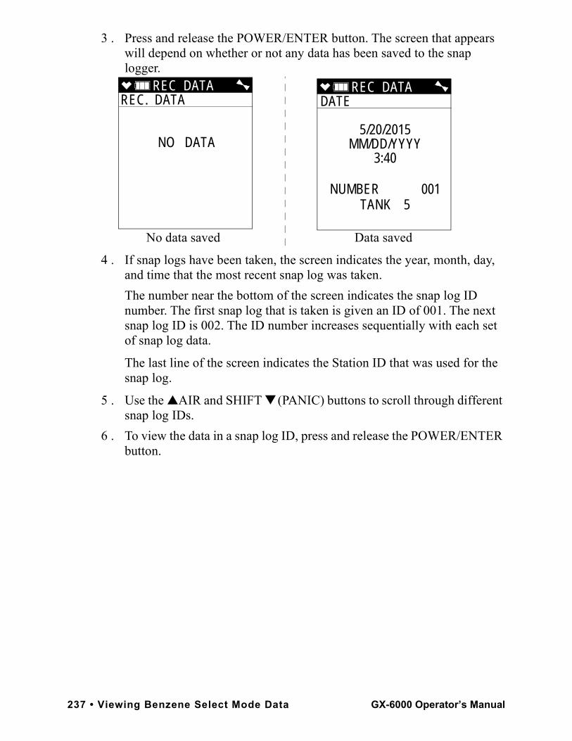
3 . Press and release the POWER/ENTER button. The screen that appears will depend on whether or not any data has been saved to the snap logger.
4 . If snap logs have been taken, the screen indicates the year, month, day, and time that the most recent snap log was taken. The number near the bottom of the screen indicates the snap log ID number. The first snap log that is taken is given an ID of 001. The next snap log ID is 002. The ID number increases sequentially with each set of snap log data.
The last line of the screen indicates the Station ID that was used for the snap log.
5 . Use the ▲AIR and SHIFT ▼ (PANIC) buttons to scroll through different snap log IDs.
6 . To view the data in a snap log ID, press and release the POWER/ENTER button.
REC DATA REC. DATA
NO DATA
REC DATA DATE
5/20/2015MM/DD/YYYY
3:40
NUMBER 001TANK 5
No data saved Data saved
237 • Viewing Benzene Select Mode Data GX-6000 Operator’s Manual
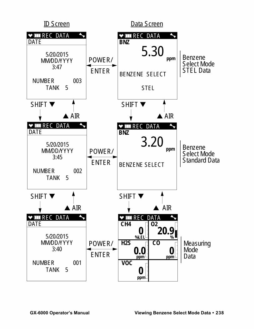
REC DATA DATE
5/20/2015MM/DD/YYYY
3:47
NUMBER 003TANK 5
REC DATA DATE
5/20/2015MM/DD/YYYY
3:45
NUMBER 002TANK 5
REC DATA DATE
5/20/2015MM/DD/YYYY
3:40
NUMBER 001TANK 5
POWER/
ENTER
POWER/
ENTER
POWER/
ENTER
SHIFT ▼
▲ AIR
SHIFT ▼
▲ AIR
BenzeneSelect ModeSTEL Data
Benzene Select Mode Standard Data
MeasuringModeData
SHIFT ▼
▲ AIR
SHIFT ▼
▲ AIR
ID Screen Data Screen
REC DATA BNZ
BENZENE SELECT
STEL
5.30 ppm
REC DATA BNZ
BENZENE SELECT
3.20 ppm
REC DATA CH4 O2
%LEL % H2S CO
ppm ppm
VOC
ppm
0 20.9
0.0 0
0
GX-6000 Operator’s Manual Viewing Benzene Select Mode Data • 238
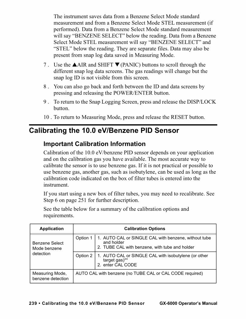
The instrument saves data from a Benzene Select Mode standard measurement and from a Benzene Select Mode STEL measurement (if performed). Data from a Benzene Select Mode standard measurement will say “BENZENE SELECT” below the reading. Data from a Benzene Select Mode STEL measurement will say “BENZENE SELECT” and “STEL” below the reading. They are separate files. Data may also be present from snap log data saved in Measuring Mode.
7 . Use the ▲AIR and SHIFT ▼ (PANIC) buttons to scroll through the different snap log data screens. The gas readings will change but the snap log ID is not visible from this screen.
8 . You can also go back and forth between the ID and data screens by pressing and releasing the POWER/ENTER button.
9 . To return to the Snap Logging Screen, press and release the DISP/LOCK button.
10 . To return to Measuring Mode, press and release the RESET button.
Calibrating the 10.0 eV/Benzene PID Sensor
Important Calibration InformationCalibration of the 10.0 eV/benzene PID sensor depends on your application and on the calibration gas you have available. The most accurate way to calibrate the sensor is to use benzene gas. If it is not practical or possible to use benzene gas, another gas, such as isobutylene, can be used as long as the calibration code indicated on the box of filter tubes is entered into the instrument. If you start using a new box of filter tubes, you may need to recalibrate. See Step 6 on page 251 for further description.See the table below for a summary of the calibration options and requirements.
Application Calibration Options
Benzene Select Mode benzene detection
Option 1 1. AUTO CAL or SINGLE CAL with benzene, without tube and holder
2. TUBE CAL with benzene, with tube and holder
Option 2 1. AUTO CAL or SINGLE CAL with isobutylene (or other target gas)**
2. enter CAL CODE
Measuring Mode, benzene detection
AUTO CAL with benzene (no TUBE CAL or CAL CODE required)
239 • Calibrating the 10.0 eV/Benzene PID Sensor GX-6000 Operator’s Manual
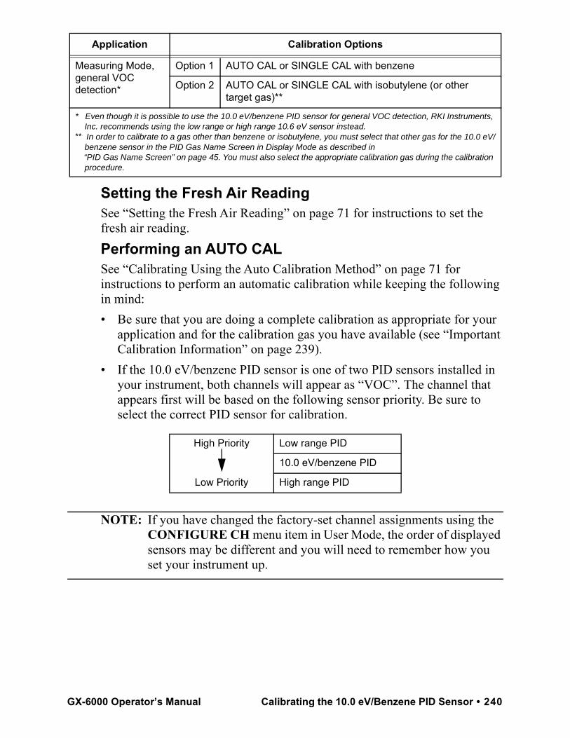
Setting the Fresh Air ReadingSee “Setting the Fresh Air Reading” on page 71 for instructions to set the fresh air reading.Performing an AUTO CALSee “Calibrating Using the Auto Calibration Method” on page 71 for instructions to perform an automatic calibration while keeping the following in mind: • Be sure that you are doing a complete calibration as appropriate for your
application and for the calibration gas you have available (see “Important Calibration Information” on page 239).
• If the 10.0 eV/benzene PID sensor is one of two PID sensors installed in your instrument, both channels will appear as “VOC”. The channel that appears first will be based on the following sensor priority. Be sure to select the correct PID sensor for calibration.
NOTE: If you have changed the factory-set channel assignments using the CONFIGURE CH menu item in User Mode, the order of displayed sensors may be different and you will need to remember how you set your instrument up.
Measuring Mode, general VOC detection*
Option 1 AUTO CAL or SINGLE CAL with benzene
Option 2 AUTO CAL or SINGLE CAL with isobutylene (or other target gas)**
* Even though it is possible to use the 10.0 eV/benzene PID sensor for general VOC detection, RKI Instruments, Inc. recommends using the low range or high range 10.6 eV sensor instead.** In order to calibrate to a gas other than benzene or isobutylene, you must select that other gas for the 10.0 eV/ benzene sensor in the PID Gas Name Screen in Display Mode as described in “PID Gas Name Screen” on page 45. You must also select the appropriate calibration gas during the calibration procedure.
High Priority
Low Priority
Low range PID
10.0 eV/benzene PID
High range PID
Application Calibration Options
GX-6000 Operator’s Manual Calibrating the 10.0 eV/Benzene PID Sensor • 240
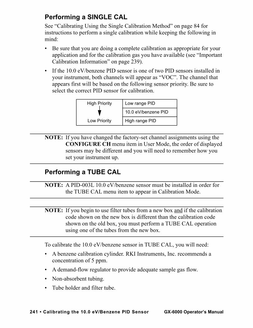
Performing a SINGLE CALSee “Calibrating Using the Single Calibration Method” on page 84 for instructions to perform a single calibration while keeping the following in mind:• Be sure that you are doing a complete calibration as appropriate for your
application and for the calibration gas you have available (see “Important Calibration Information” on page 239).
• If the 10.0 eV/benzene PID sensor is one of two PID sensors installed in your instrument, both channels will appear as “VOC”. The channel that appears first will be based on the following sensor priority. Be sure to select the correct PID sensor for calibration.
NOTE: If you have changed the factory-set channel assignments using the CONFIGURE CH menu item in User Mode, the order of displayed sensors may be different and you will need to remember how you set your instrument up.
Performing a TUBE CAL
NOTE: A PID-003L 10.0 eV/benzene sensor must be installed in order for the TUBE CAL menu item to appear in Calibration Mode.
NOTE: If you begin to use filter tubes from a new box and if the calibration code shown on the new box is different than the calibration code shown on the old box, you must perform a TUBE CAL operation using one of the tubes from the new box.
To calibrate the 10.0 eV/benzene sensor in TUBE CAL, you will need:• A benzene calibration cylinder. RKI Instruments, Inc. recommends a
concentration of 5 ppm.• A demand-flow regulator to provide adequate sample gas flow.• Non-absorbent tubing.• Tube holder and filter tube.
High Priority
Low Priority
Low range PID
10.0 eV/benzene PID
High range PID
241 • Calibrating the 10.0 eV/Benzene PID Sensor GX-6000 Operator’s Manual
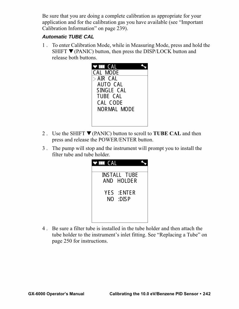
Be sure that you are doing a complete calibration as appropriate for your application and for the calibration gas you have available (see “Important Calibration Information” on page 239).Automatic TUBE CAL1 . To enter Calibration Mode, while in Measuring Mode, press and hold the
SHIFT ▼ (PANIC) button, then press the DISP/LOCK button and release both buttons.
2 . Use the SHIFT ▼ (PANIC) button to scroll to TUBE CAL and then press and release the POWER/ENTER button.
3 . The pump will stop and the instrument will prompt you to install the filter tube and tube holder.
4 . Be sure a filter tube is installed in the tube holder and then attach the tube holder to the instrument’s inlet fitting. See “Replacing a Tube” on page 250 for instructions.
CAL CAL MODE
AIR CAL AUTO CAL SINGLE CAL TUBE CAL CAL CODE NORMAL MODE
CAL
INSTALL TUBEAND HOLDER
YES :ENTERNO :DISP
GX-6000 Operator’s Manual Calibrating the 10.0 eV/Benzene PID Sensor • 242
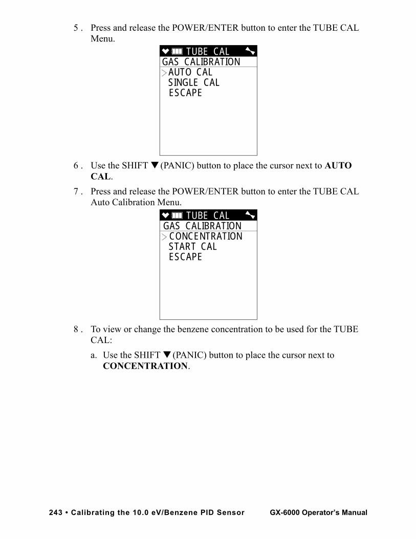
5 . Press and release the POWER/ENTER button to enter the TUBE CAL Menu.
6 . Use the SHIFT ▼ (PANIC) button to place the cursor next to AUTO CAL.
7 . Press and release the POWER/ENTER button to enter the TUBE CAL Auto Calibration Menu.
8 . To view or change the benzene concentration to be used for the TUBE CAL:
a. Use the SHIFT ▼ (PANIC) button to place the cursor next to CONCENTRATION.
TUBE CAL GAS CALIBRATION
AUTO CAL SINGLE CAL ESCAPE
TUBE CAL GAS CALIBRATION
CONCENTRATION START CAL ESCAPE
243 • Calibrating the 10.0 eV/Benzene PID Sensor GX-6000 Operator’s Manual
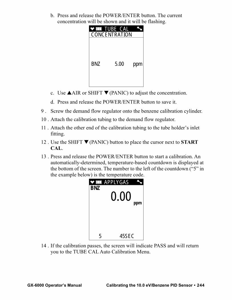
b. Press and release the POWER/ENTER button. The current concentration will be shown and it will be flashing.
c. Use ▲AIR or SHIFT ▼ (PANIC) to adjust the concentration.
d. Press and release the POWER/ENTER button to save it.
9 . Screw the demand flow regulator onto the benzene calibration cylinder. 10 . Attach the calibration tubing to the demand flow regulator.11 . Attach the other end of the calibration tubing to the tube holder’s inlet
fitting.12 . Use the SHIFT ▼ (PANIC) button to place the cursor next to START
CAL.13 . Press and release the POWER/ENTER button to start a calibration. An
automatically-determined, temperature-based countdown is displayed at the bottom of the screen. The number to the left of the countdown (“5” in the example below) is the temperature code.
14 . If the calibration passes, the screen will indicate PASS and will return you to the TUBE CAL Auto Calibration Menu.
TUBE CALCONCENTRATION
BNZ 5.00 ppm
APPLYGASBNZ
5 45SEC
0.00 ppm
GX-6000 Operator’s Manual Calibrating the 10.0 eV/Benzene PID Sensor • 244
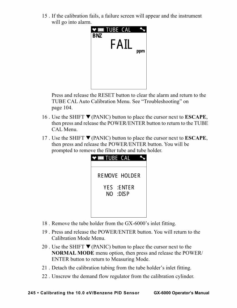
15 . If the calibration fails, a failure screen will appear and the instrument will go into alarm.
Press and release the RESET button to clear the alarm and return to the TUBE CAL Auto Calibration Menu. See “Troubleshooting” on page 104.
16 . Use the SHIFT ▼ (PANIC) button to place the cursor next to ESCAPE, then press and release the POWER/ENTER button to return to the TUBE CAL Menu.
17 . Use the SHIFT ▼ (PANIC) button to place the cursor next to ESCAPE, then press and release the POWER/ENTER button. You will be prompted to remove the filter tube and tube holder.
18 . Remove the tube holder from the GX-6000’s inlet fitting.19 . Press and release the POWER/ENTER button. You will return to the
Calibration Mode Menu.20 . Use the SHIFT ▼ (PANIC) button to place the cursor next to the
NORMAL MODE menu option, then press and release the POWER/ENTER button to return to Measuring Mode.
21 . Detach the calibration tubing from the tube holder’s inlet fitting.22 . Unscrew the demand flow regulator from the calibration cylinder.
TUBE CAL BNZ
FAIL
ppm
TUBE CAL
REMOVE HOLDER
YES :ENTERNO :DISP
245 • Calibrating the 10.0 eV/Benzene PID Sensor GX-6000 Operator’s Manual
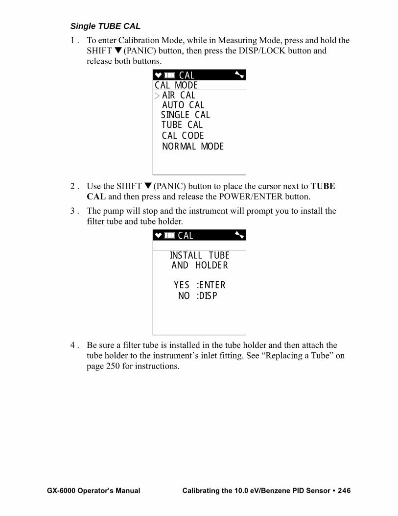
Single TUBE CAL1 . To enter Calibration Mode, while in Measuring Mode, press and hold the
SHIFT ▼ (PANIC) button, then press the DISP/LOCK button and release both buttons.
2 . Use the SHIFT ▼ (PANIC) button to place the cursor next to TUBE CAL and then press and release the POWER/ENTER button.
3 . The pump will stop and the instrument will prompt you to install the filter tube and tube holder.
4 . Be sure a filter tube is installed in the tube holder and then attach the tube holder to the instrument’s inlet fitting. See “Replacing a Tube” on page 250 for instructions.
CAL CAL MODE
AIR CAL AUTO CAL SINGLE CAL TUBE CAL CAL CODE NORMAL MODE
CAL
INSTALL TUBEAND HOLDER
YES :ENTERNO :DISP
GX-6000 Operator’s Manual Calibrating the 10.0 eV/Benzene PID Sensor • 246
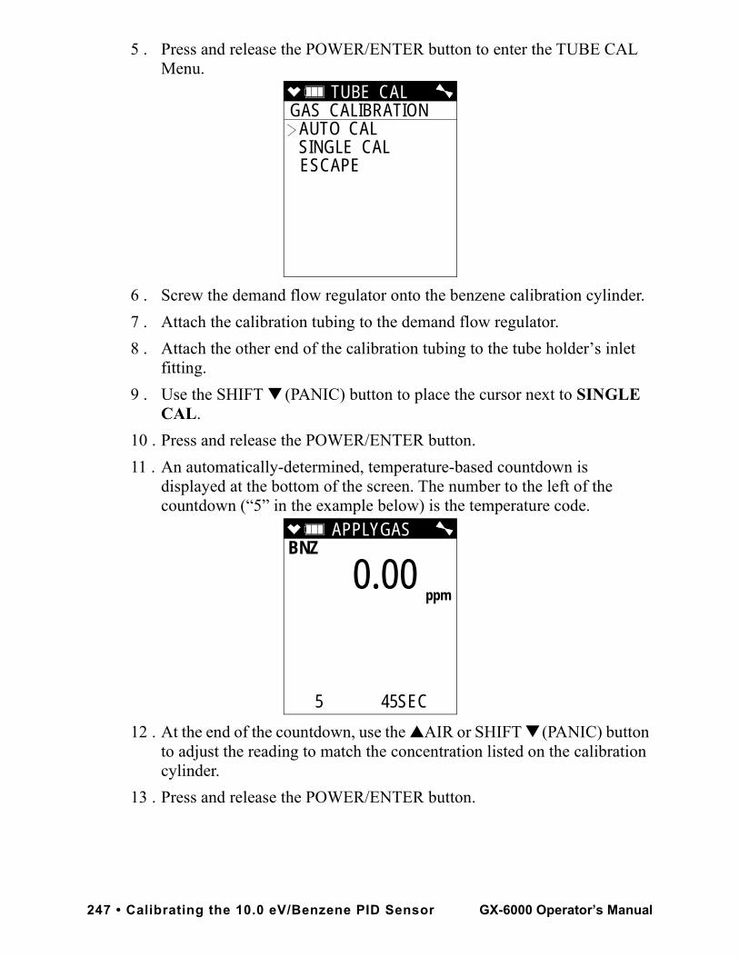
5 . Press and release the POWER/ENTER button to enter the TUBE CAL Menu.
6 . Screw the demand flow regulator onto the benzene calibration cylinder. 7 . Attach the calibration tubing to the demand flow regulator.8 . Attach the other end of the calibration tubing to the tube holder’s inlet
fitting.9 . Use the SHIFT ▼ (PANIC) button to place the cursor next to SINGLE
CAL.10 . Press and release the POWER/ENTER button.11 . An automatically-determined, temperature-based countdown is
displayed at the bottom of the screen. The number to the left of the countdown (“5” in the example below) is the temperature code.
12 . At the end of the countdown, use the ▲AIR or SHIFT ▼ (PANIC) button to adjust the reading to match the concentration listed on the calibration cylinder.
13 . Press and release the POWER/ENTER button.
TUBE CAL GAS CALIBRATION
AUTO CAL SINGLE CAL ESCAPE
APPLYGASBNZ
5 45SEC
0.00 ppm
247 • Calibrating the 10.0 eV/Benzene PID Sensor GX-6000 Operator’s Manual
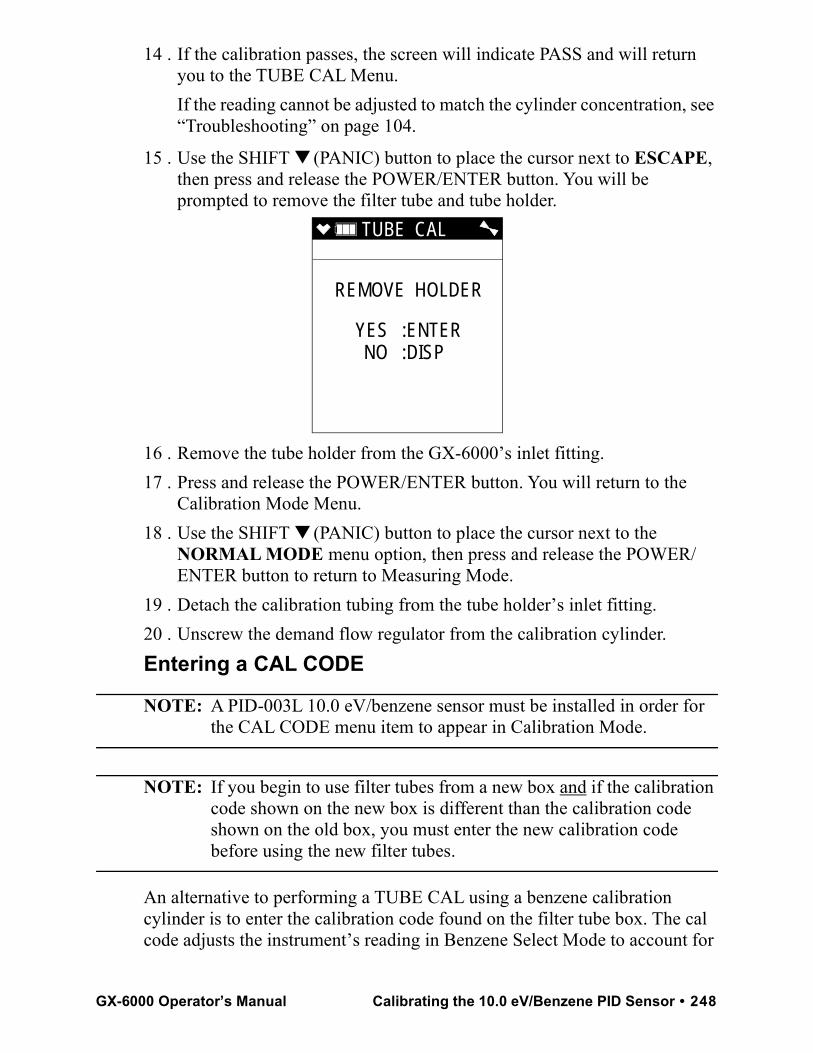
14 . If the calibration passes, the screen will indicate PASS and will return you to the TUBE CAL Menu.If the reading cannot be adjusted to match the cylinder concentration, see “Troubleshooting” on page 104.
15 . Use the SHIFT ▼ (PANIC) button to place the cursor next to ESCAPE, then press and release the POWER/ENTER button. You will be prompted to remove the filter tube and tube holder.
16 . Remove the tube holder from the GX-6000’s inlet fitting.17 . Press and release the POWER/ENTER button. You will return to the
Calibration Mode Menu.18 . Use the SHIFT ▼ (PANIC) button to place the cursor next to the
NORMAL MODE menu option, then press and release the POWER/ENTER button to return to Measuring Mode.
19 . Detach the calibration tubing from the tube holder’s inlet fitting.20 . Unscrew the demand flow regulator from the calibration cylinder.Entering a CAL CODE
NOTE: A PID-003L 10.0 eV/benzene sensor must be installed in order for the CAL CODE menu item to appear in Calibration Mode.
NOTE: If you begin to use filter tubes from a new box and if the calibration code shown on the new box is different than the calibration code shown on the old box, you must enter the new calibration code before using the new filter tubes.
An alternative to performing a TUBE CAL using a benzene calibration cylinder is to enter the calibration code found on the filter tube box. The cal code adjusts the instrument’s reading in Benzene Select Mode to account for
TUBE CAL
REMOVE HOLDER
YES :ENTERNO :DISP
GX-6000 Operator’s Manual Calibrating the 10.0 eV/Benzene PID Sensor • 248
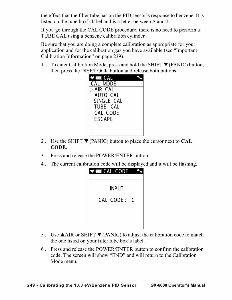
the effect that the filter tube has on the PID sensor’s response to benzene. It is listed on the tube box’s label and is a letter between A and J. If you go through the CAL CODE procedure, there is no need to perform a TUBE CAL using a benzene calibration cylinder.Be sure that you are doing a complete calibration as appropriate for your application and for the calibration gas you have available (see “Important Calibration Information” on page 239).1 . To enter Calibration Mode, press and hold the SHIFT ▼ (PANIC) button,
then press the DISP/LOCK button and release both buttons.
2 . Use the SHIFT ▼ (PANIC) button to place the cursor next to CAL CODE.
3 . Press and release the POWER/ENTER button. 4 . The current calibration code will be displayed and it will be flashing.
5 . Use ▲AIR or SHIFT ▼ (PANIC) to adjust the calibration code to match the one listed on your filter tube box’s label.
6 . Press and release the POWER/ENTER button to confirm the calibration code. The screen will show “END” and will return to the Calibration Mode menu.
CAL CAL MODE
AIR CAL AUTO CAL SINGLE CAL TUBE CAL CAL CODE ESCAPE
CAL CODE
INPUT
CAL CODE : C
249 • Calibrating the 10.0 eV/Benzene PID Sensor GX-6000 Operator’s Manual
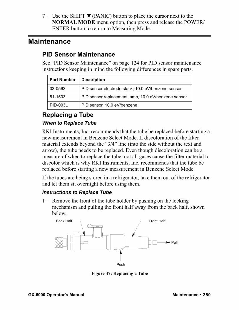
7 . Use the SHIFT ▼ (PANIC) button to place the cursor next to the NORMAL MODE menu option, then press and release the POWER/ENTER button to return to Measuring Mode.
Maintenance
PID Sensor MaintenanceSee “PID Sensor Maintenance” on page 124 for PID sensor maintenance instructions keeping in mind the following differences in spare parts.
Replacing a TubeWhen to Replace TubeRKI Instruments, Inc. recommends that the tube be replaced before starting a new measurement in Benzene Select Mode. If discoloration of the filter material extends beyond the “3/4” line (into the side without the text and arrow), the tube needs to be replaced. Even though discoloration can be a measure of when to replace the tube, not all gases cause the filter material to discolor which is why RKI Instruments, Inc. recommends that the tube be replaced before starting a new measurement in Benzene Select Mode.If the tubes are being stored in a refrigerator, take them out of the refrigerator and let them sit overnight before using them.Instructions to Replace Tube1 . Remove the front of the tube holder by pushing on the locking
mechanism and pulling the front half away from the back half, shown below.
Figure 47: Replacing a Tube
Part Number Description
33-0563 PID sensor electrode stack, 10.0 eV/benzene sensor
51-1503 PID sensor replacement lamp, 10.0 eV/benzene sensor
PID-003L PID sensor, 10.0 eV/benzene
Push
Pull
Back Half Front Half
GX-6000 Operator’s Manual Maintenance • 250
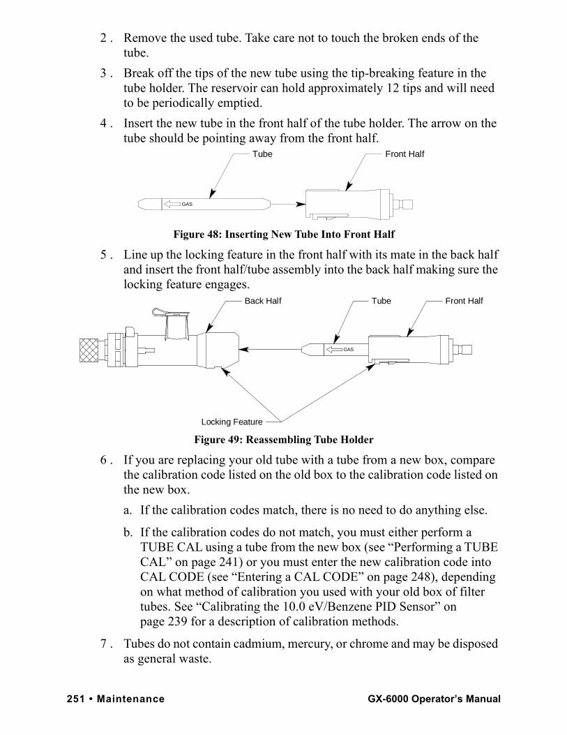
2 . Remove the used tube. Take care not to touch the broken ends of the tube.
3 . Break off the tips of the new tube using the tip-breaking feature in the tube holder. The reservoir can hold approximately 12 tips and will need to be periodically emptied.
4 . Insert the new tube in the front half of the tube holder. The arrow on the tube should be pointing away from the front half.
Figure 48: Inserting New Tube Into Front Half
5 . Line up the locking feature in the front half with its mate in the back half and insert the front half/tube assembly into the back half making sure the locking feature engages.
Figure 49: Reassembling Tube Holder
6 . If you are replacing your old tube with a tube from a new box, compare the calibration code listed on the old box to the calibration code listed on the new box.
a. If the calibration codes match, there is no need to do anything else.
b. If the calibration codes do not match, you must either perform a TUBE CAL using a tube from the new box (see “Performing a TUBE CAL” on page 241) or you must enter the new calibration code into CAL CODE (see “Entering a CAL CODE” on page 248), depending on what method of calibration you used with your old box of filter tubes. See “Calibrating the 10.0 eV/Benzene PID Sensor” on page 239 for a description of calibration methods.
7 . Tubes do not contain cadmium, mercury, or chrome and may be disposed as general waste.
Front HalfTube
GAS
Front HalfTube
GAS
Back Half
Locking Feature
251 • Maintenance GX-6000 Operator’s Manual
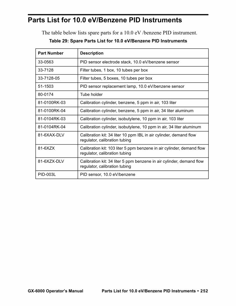
Parts List for 10.0 eV/Benzene PID InstrumentsThe table below lists spare parts for a 10.0 eV /benzene PID instrument.
Table 29: Spare Parts List for 10.0 eV/Benzene PID Instruments
Part Number Description
33-0563 PID sensor electrode stack, 10.0 eV/benzene sensor
33-7128 Filter tubes, 1 box, 10 tubes per box
33-7128-05 Filter tubes, 5 boxes, 10 tubes per box
51-1503 PID sensor replacement lamp, 10.0 eV/benzene sensor
80-0174 Tube holder
81-0100RK-03 Calibration cylinder, benzene, 5 ppm in air, 103 liter
81-0100RK-04 Calibration cylinder, benzene, 5 ppm in air, 34 liter aluminum
81-0104RK-03 Calibration cylinder, isobutylene, 10 ppm in air, 103 liter
81-0104RK-04 Calibration cylinder, isobutylene, 10 ppm in air, 34 liter aluminum
81-6XAX-DLV Calibration kit: 34 liter 10 ppm IBL in air cylinder, demand flow regulator, calibration tubing
81-6XZX Calibration kit: 103 liter 5 ppm benzene in air cylinder, demand flow regulator, calibration tubing
81-6XZX-DLV Calibration kit: 34 liter 5 ppm benzene in air cylinder, demand flow regulator, calibration tubing
PID-003L PID sensor, 10.0 eV/benzene
GX-6000 Operator’s Manual Parts List for 10.0 eV/Benzene PID Instruments • 252
WarrantyRKI Instruments, Inc. warrants the GX-6000 sold by us to be free from defects in materials, workmanship, and performance for a period of two years from the date of shipment from RKI Instruments, Inc. This includes the instrument and the original sensors. Replacement parts are warranted for 1 year from the date of their shipment from RKI Instruments, Inc. except for replacement sensors which are warranted for 2 years. Any parts found defective within their warranty period will be repaired or replaced, at our option, free of charge. This warranty does not apply to those items which by their nature are subject to deterioration or consumption in normal service, and which must be cleaned, repaired, or replaced on a routine basis. Examples of such items are:
Warranty is voided by abuse including mechanical damage, alteration, rough handling, or repair procedures not in accordance with the instruction manual. This warranty indicates the full extent of our liability, and we are not responsible for removal or replacement costs, local repair costs, transportation costs, or contingent expenses incurred without our prior approval.
THIS WARRANTY IS EXPRESSLY IN LIEU OF ANY AND ALL OTHER WARRANTIES AND REPRESENTATIONS, EXPRESSED OR IMPLIED, AND ALL OTHER OBLIGATIONS OR LIABILITIES ON THE PART OF RKI INSTRUMENTS, INC. INCLUDING BUT NOT LIMITED TO THE WARRANTY OF MERCHANTABILITY OR FITNESS FOR A PARTICULAR PURPOSE. IN NO EVENT SHALL RKI INSTRUMENTS, INC. BE LIABLE FOR INDIRECT, INCIDENTAL, OR CONSEQUENTIAL LOSS OR DAMAGE OF ANY KIND CONNECTED WITH THE USE OF ITS PRODUCTS OR FAILURE OF ITS PRODUCTS TO FUNCTION OR OPERATE PROPERLY.
This warranty covers instruments and parts sold to users only by authorized distributors, dealers, and representatives as appointed by RKI Instruments, Inc.We do not assume indemnification for any accident or damage caused by the operation of this gas monitor and our warranty is limited to replacement of parts or our complete goods.
Absorbent cartridges
Filter elements, disks, or sheets
Pump diaphragms and valves
253 • Warranty GX-6000 Operator’s Manual